.JPG.ca33079f5815b861e67b9c2cccd37982.JPG)

Blue Ensign
-
Posts
4,564 -
Joined
-
Last visited
Content Type
Profiles
Forums
Gallery
Events
Everything posted by Blue Ensign
-
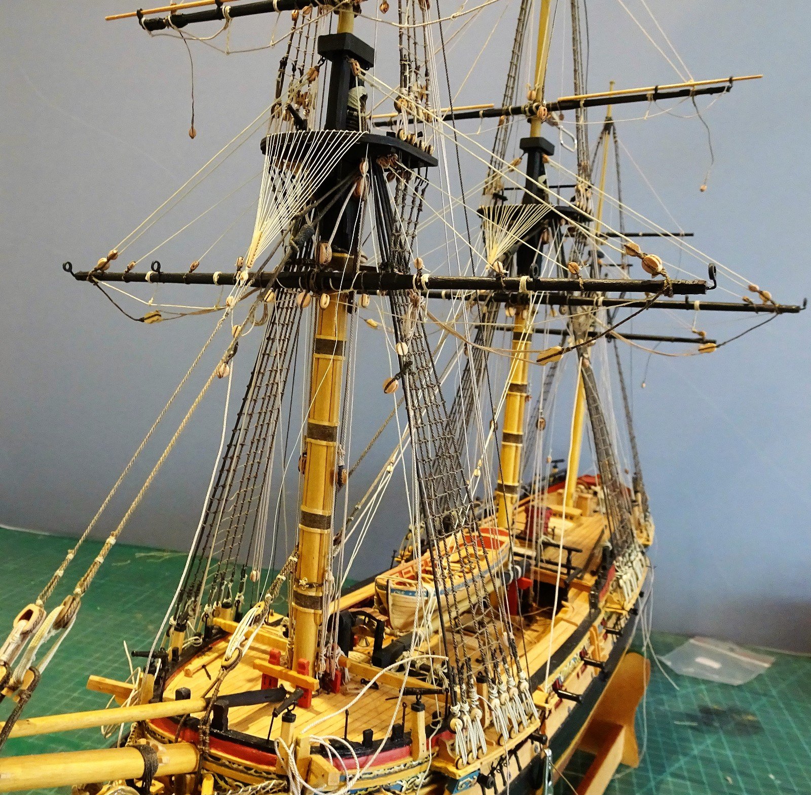
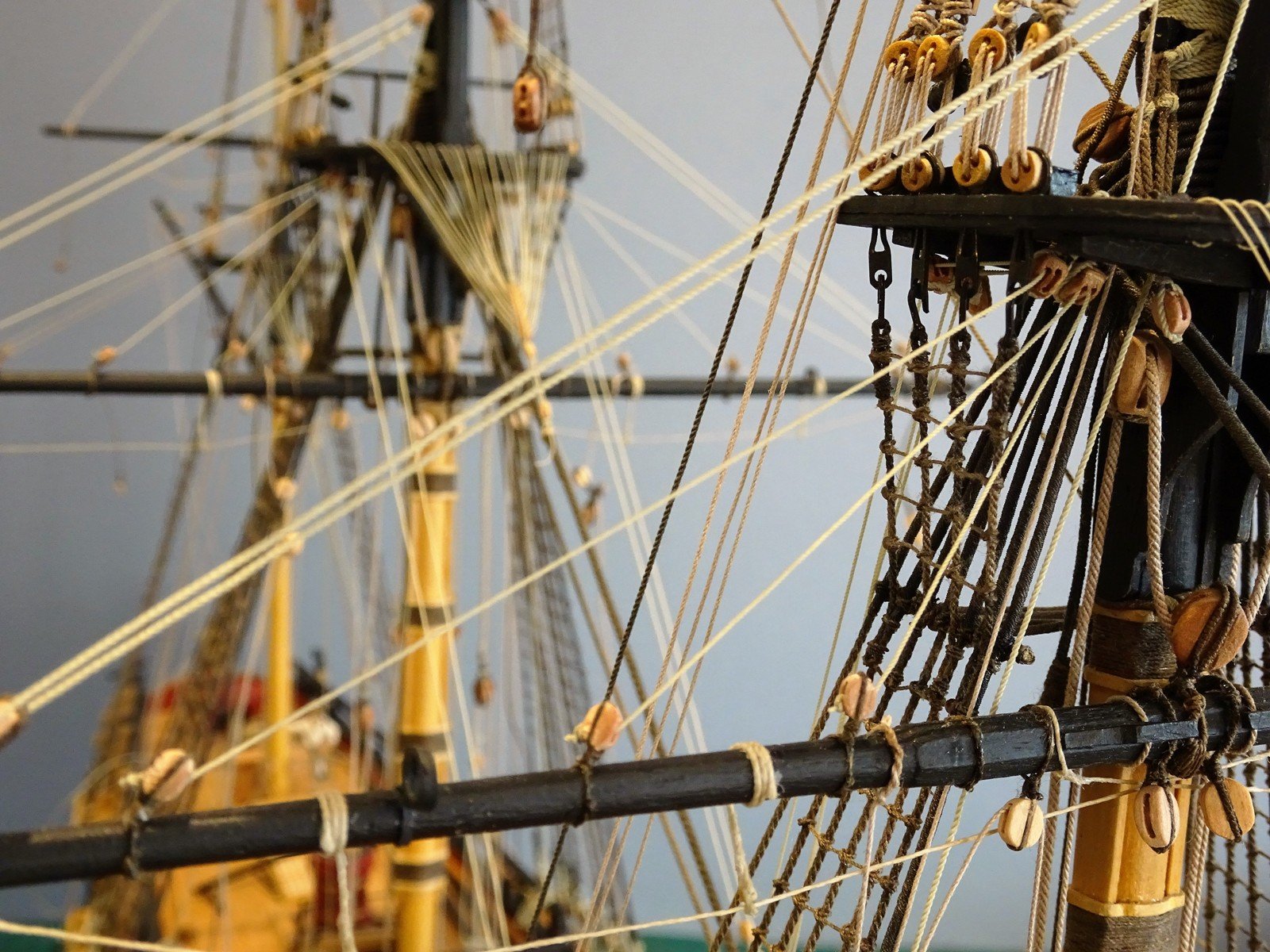
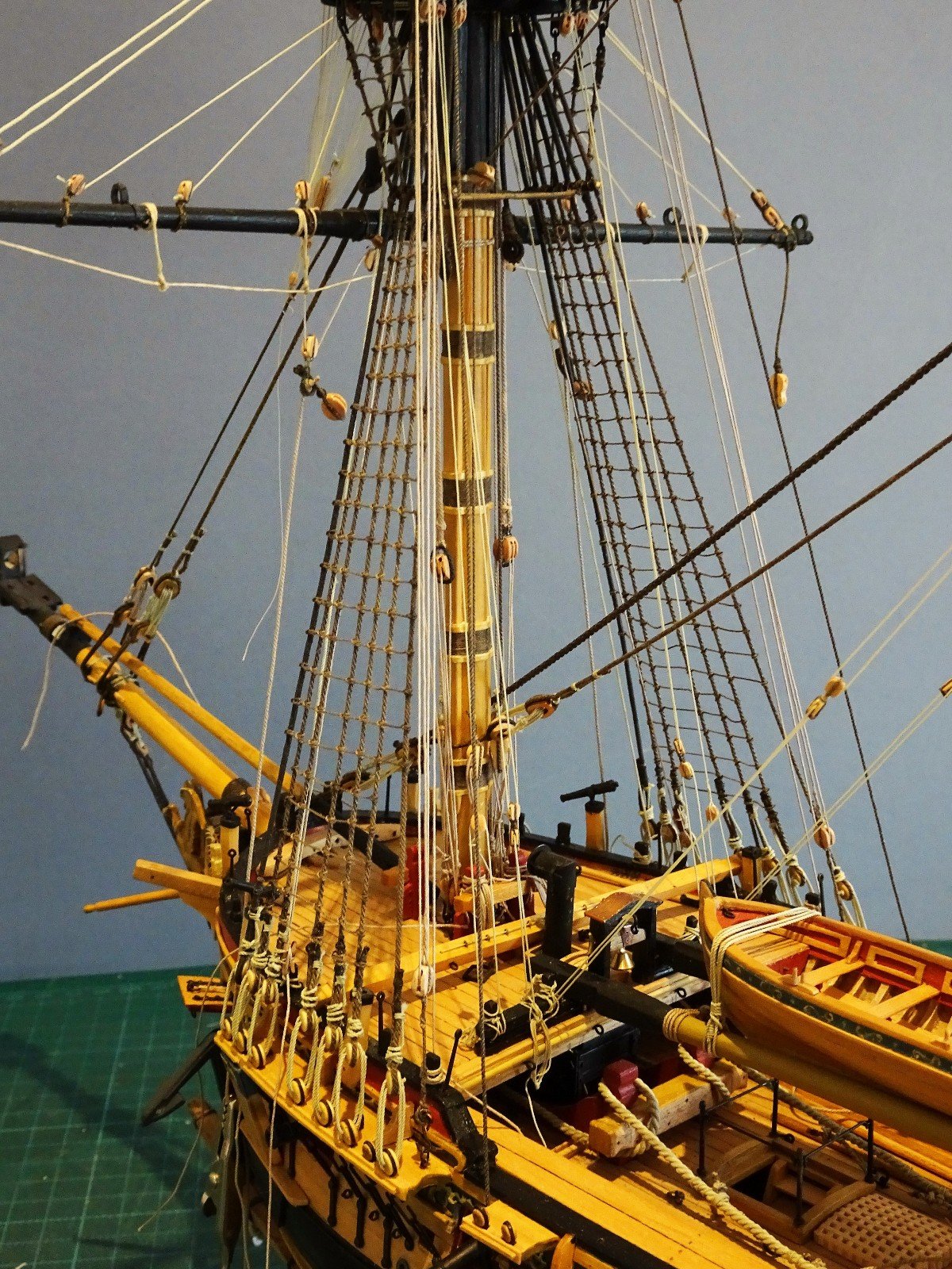
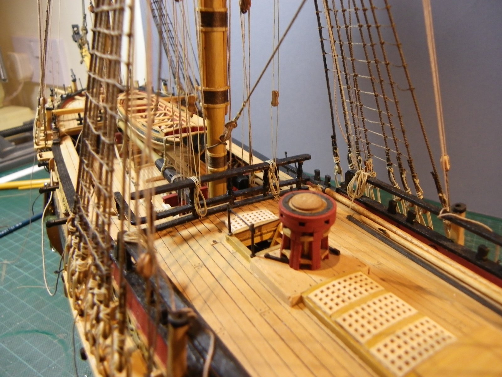
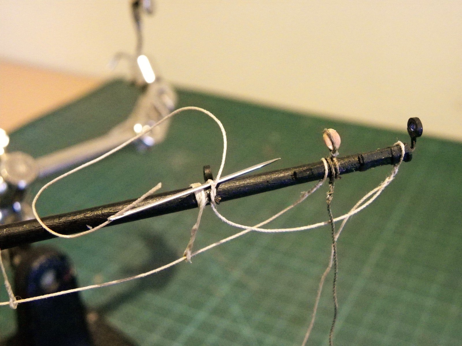
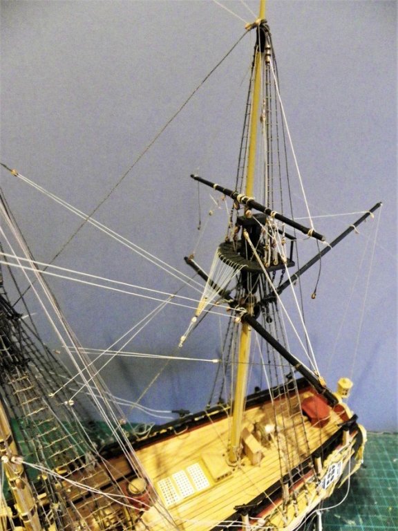
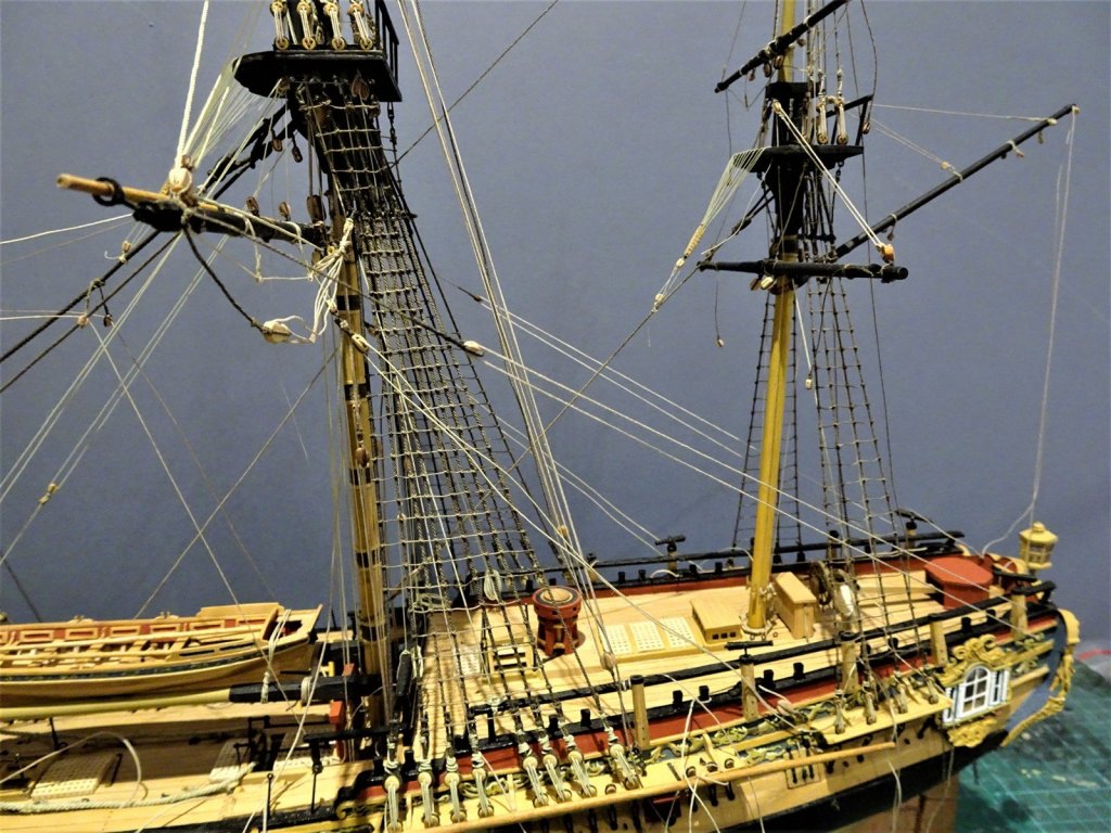
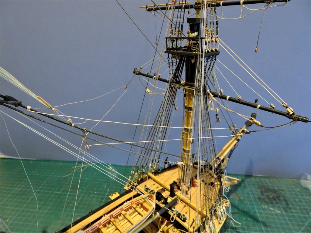
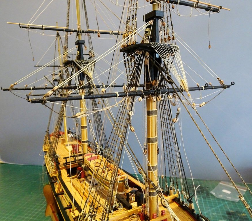
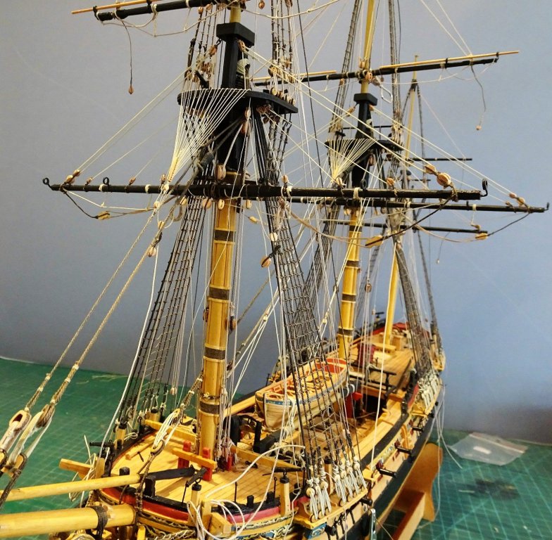
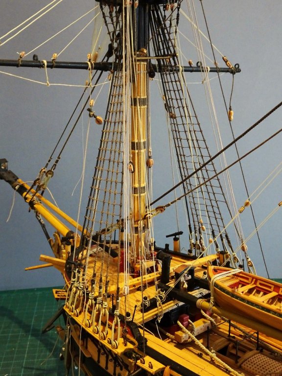
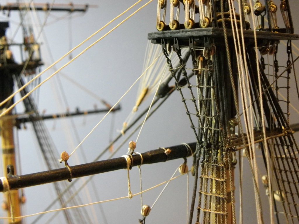
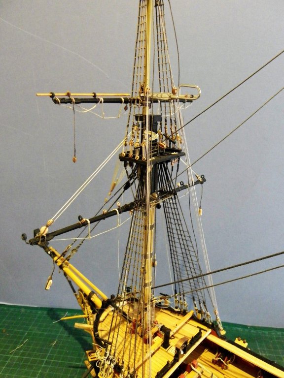
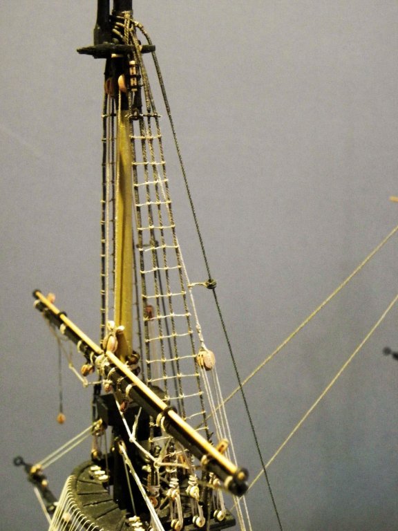
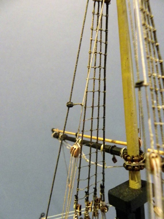
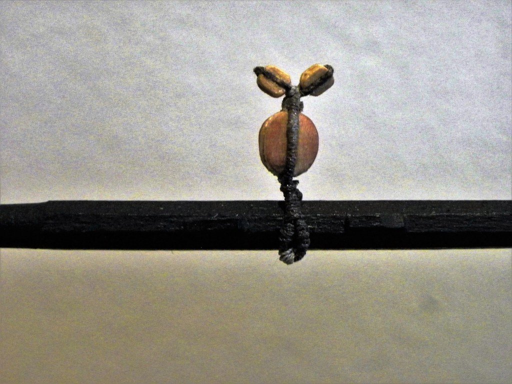
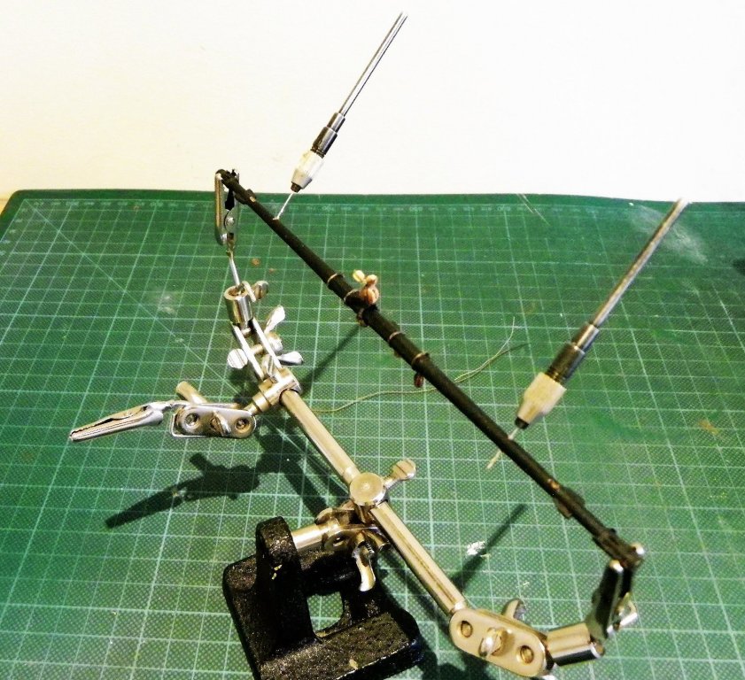
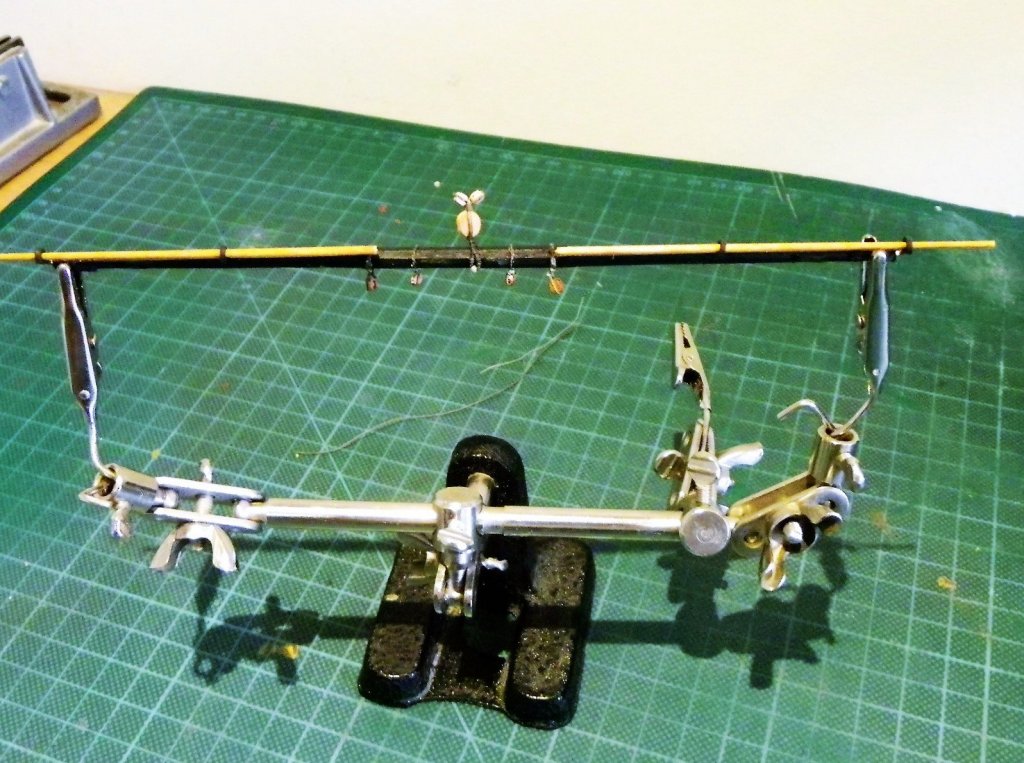
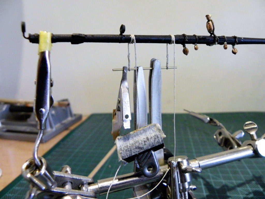
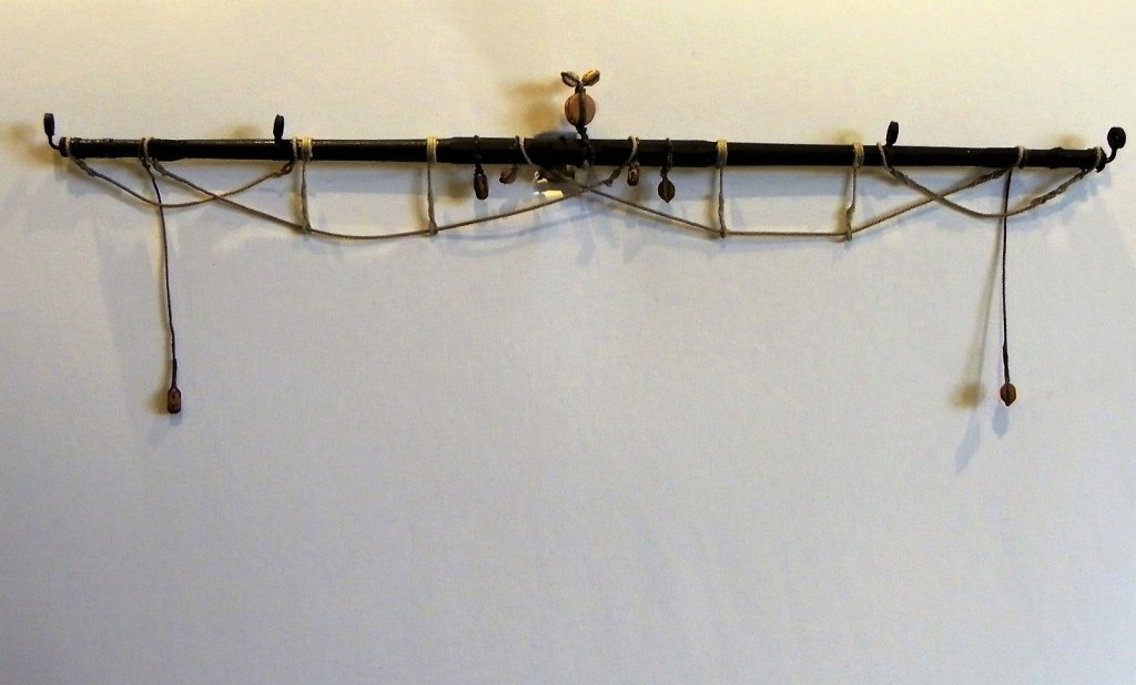
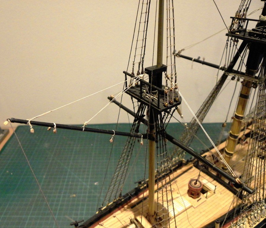
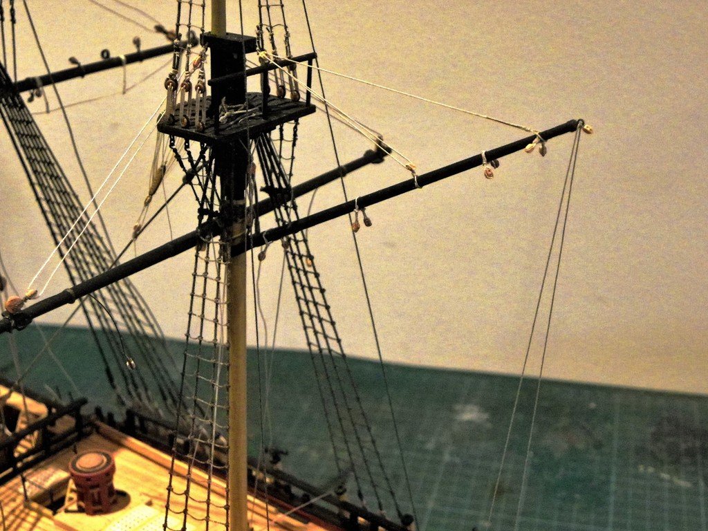
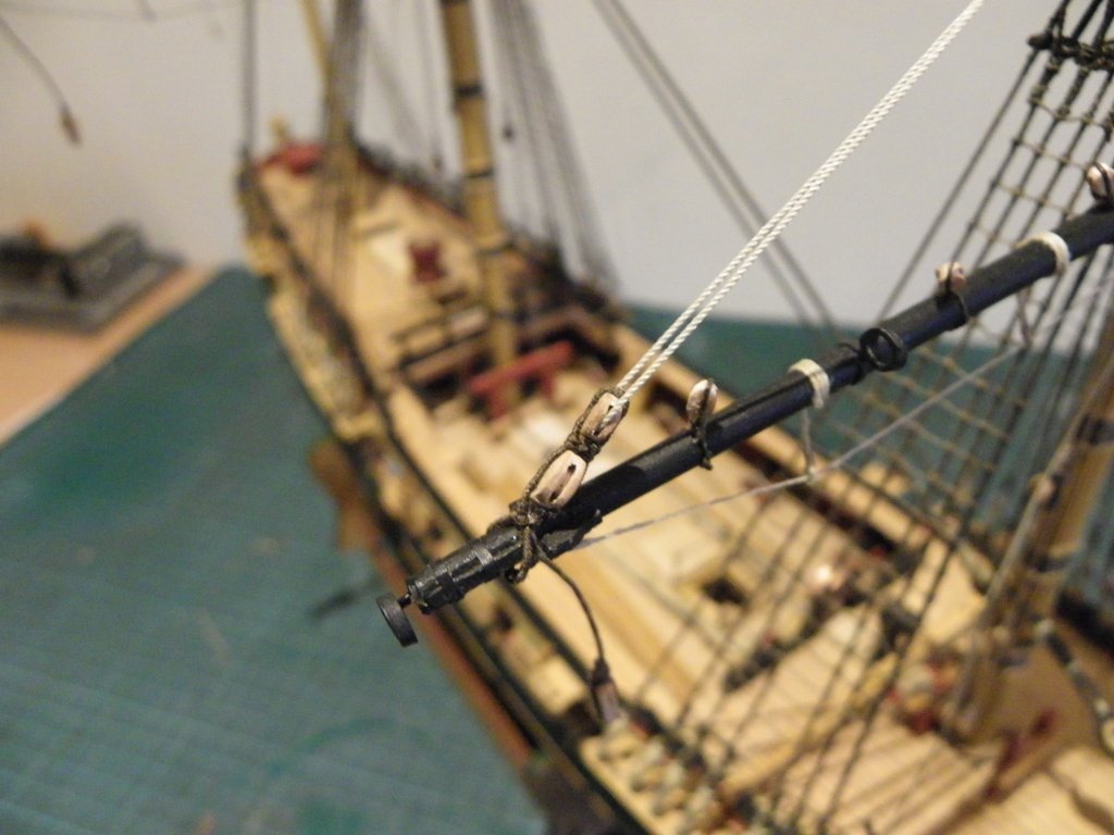
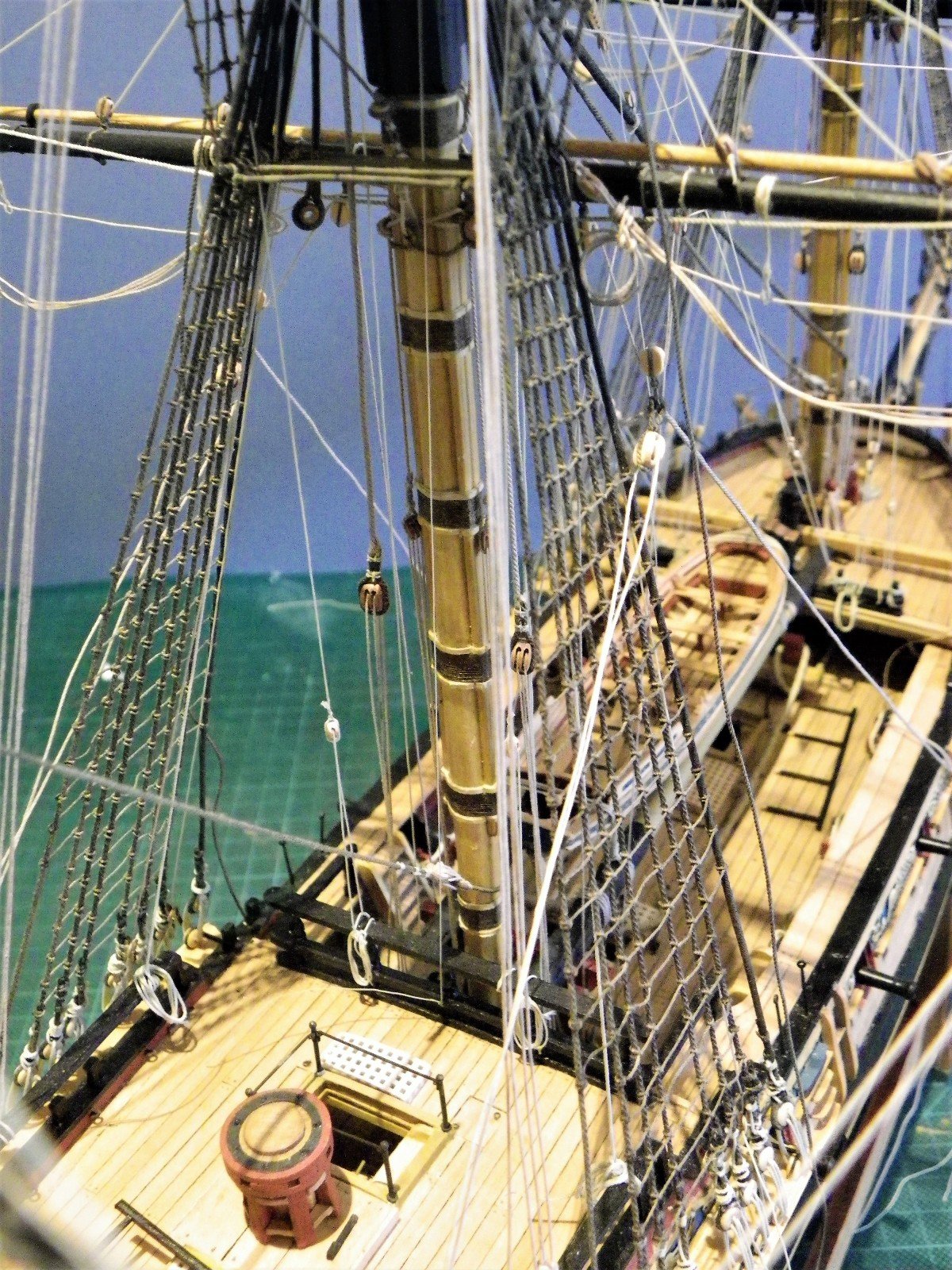
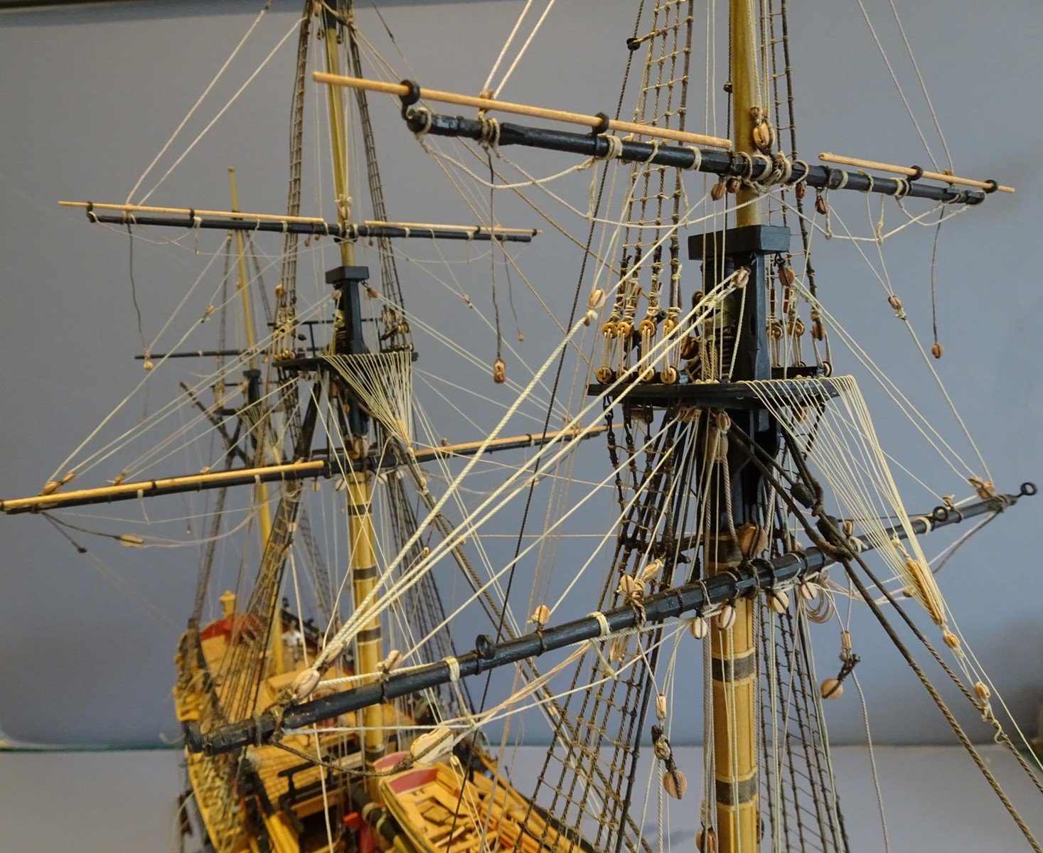
 Lashing the Studding Booms I have left the lashing of the booms perhaps a little too long but it certainly needs to be done now because the process will disturb the yards and may affect the other rigging. Fore and Fore Topsail yard booms. Main and Main topsail yard booms Extended the booms beyond the irons the minimum I could get away with as it ultimately affects the size of the case. I used Syren 0.20mm line for the purpose. This is probably my last pre Christmas build update, so may I wish all our members, and particularly those who have supported my build a very Happy Christmas, and thank you all for sharing your technical skills and providing the pleasure of your own wonderful builds. 15/12/2016. B.E.


- 366 replies
-
- 2
-

-
- pegasus
- victory models
- (and 2 more)
-
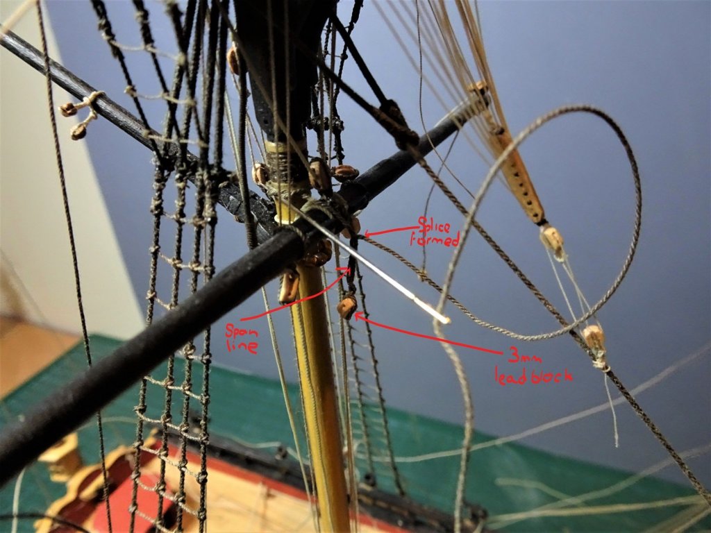
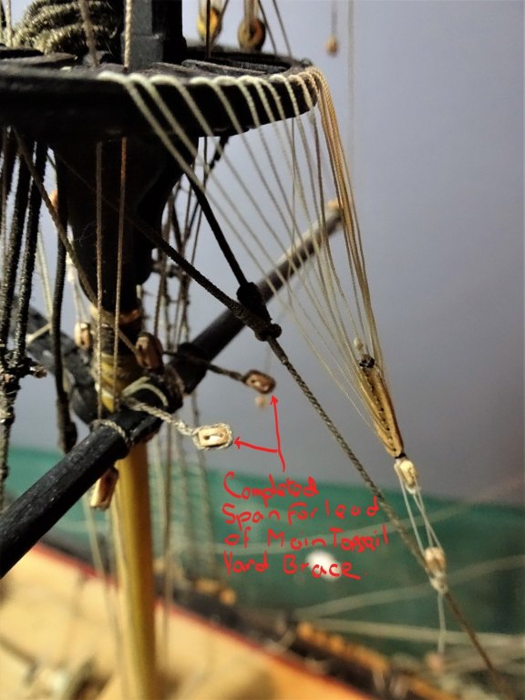
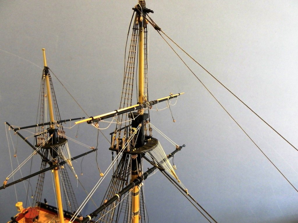
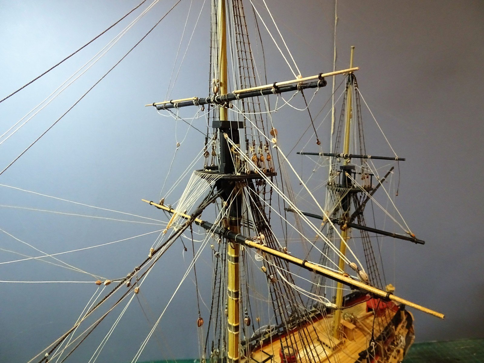
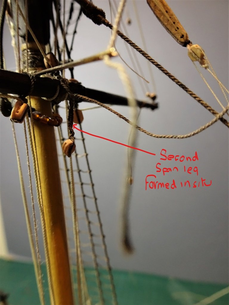
Main Topsail Yard Brace lead blocks - never too soon to attach In considering the T'gallant brace runs, I also re-checked those for the Topsail yards. Oh dear (or words similar) the Main Topsail braces run to (2)single blocks in a span just below the Mizen mast hounds above the gaff and below the woolding. This now presents a real problem in hitching the span around the mast because of all the lines already rigged. How to proceed. I firstly spliced a block into one end of a length of 0.45mm line, the line had to be taken around the Mizen threading it thro' the existing lines. A simple overhand loop retaining the blocked end of the span at the correct length was made and the line taken back around the Mizen. Now the tricky bit:- I used a smear of ca on the line at the matching length of span onto which the block groove was laid, and when set the line was brought up and over to secure the block, again secured with a spot of ca. A false splice was then made threading the free end of the span line thro' the standing part around the block to form the splice to secure the block. Resolved now but would have been so much easier to rig this span once the Mizen mast had been stepped but before any of the rigging had been started. Something to note for future reference. With the span for the Main Topsail yard fitted I can look at the brace falls. The standing part is hitched to the span behind the blocks, leads to the brace pendant blocks on the yards, back thro' the span blocks and down to belay at the forward cleats at the foot of the Mizen mast. At this point I also look at the Fore Topsail Brace falls. These also require blocks in a span fitted around the Main Stay to take the lead; the first span sits just below the span for the Fore yard brace leads, a second also on the Mainstay sits above the break of the Foc'sle. The brace falls are secured to the Mainstay just below the standing part of the Fore Brace falls, lead thro' the pendant blocks, back to the upper span, down thro' the lower span, to belay at the Foc'sle rail. I used Morope 0.25mm line. The fitting of these spans are most easily done before the yards are fitted or any of the running rigging is attached. Crossjack yard braces The brace falls are unusual in that they cross each other, port to starboard and vice versa. The standing part is hitched to the aft Main shrouds and the lead block for the line after it has passed thro' the pendant block on the opposite side is attached to the Main shroud below the standing part. The line leads down to belay on the Qtr deck rail aft of the Main shrouds. These are a little tricky because as they cross, the lines must be clear of each other which means both standing ends and lead blocks are at slightly different heights port and starboard. One thing that remains a slight puzzlement to me with the Cro'jack braces is whether they sit one above the other entirely or whether one part of the falls passes between and below the falls of the other. I have passed the Starboard brace falls above and between the Portside falls. I used 0.20mm Syren line for the braces falls and 3/32 single blocks for the leads. 13mm long strops for the brace leads. B.E.

- 366 replies
-
- 2
-
-
- pegasus
- victory models
- (and 2 more)
-
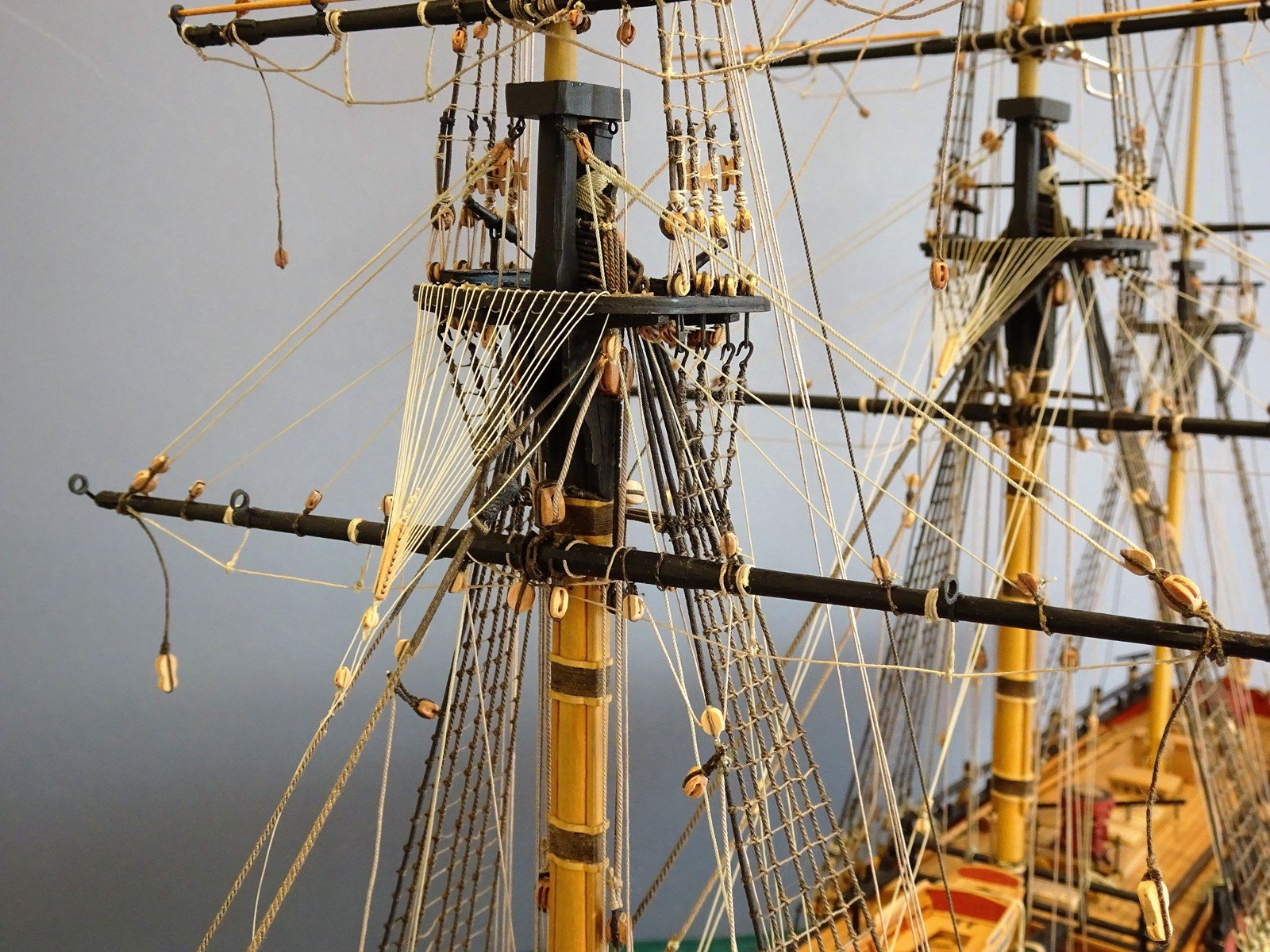
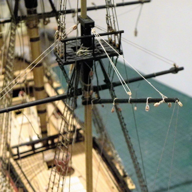
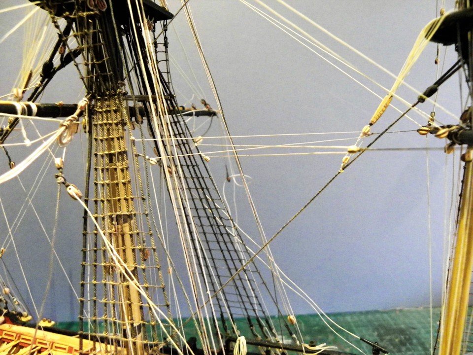
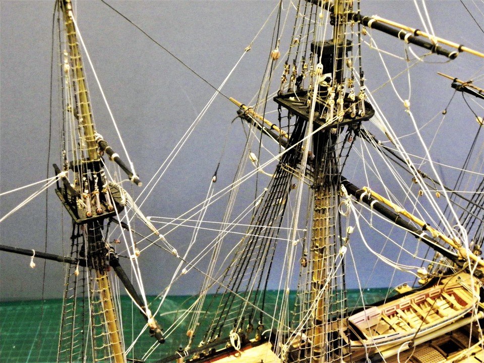
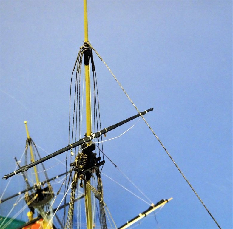
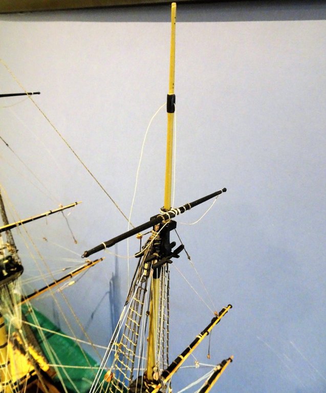
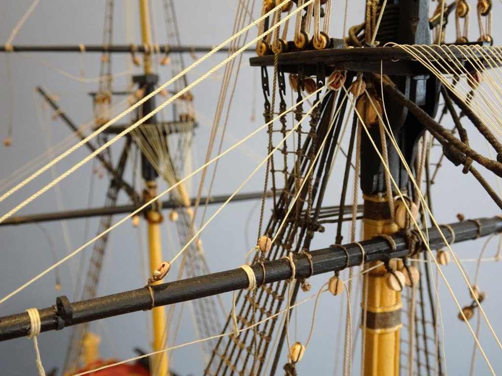
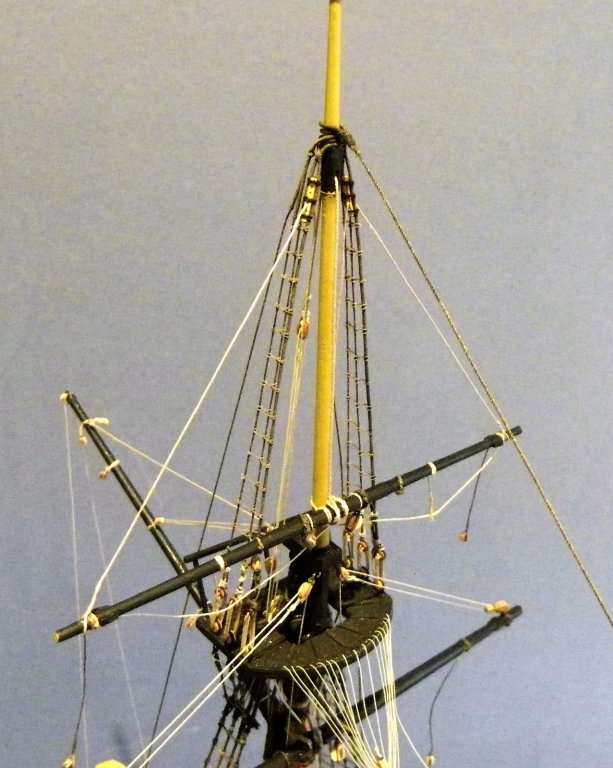
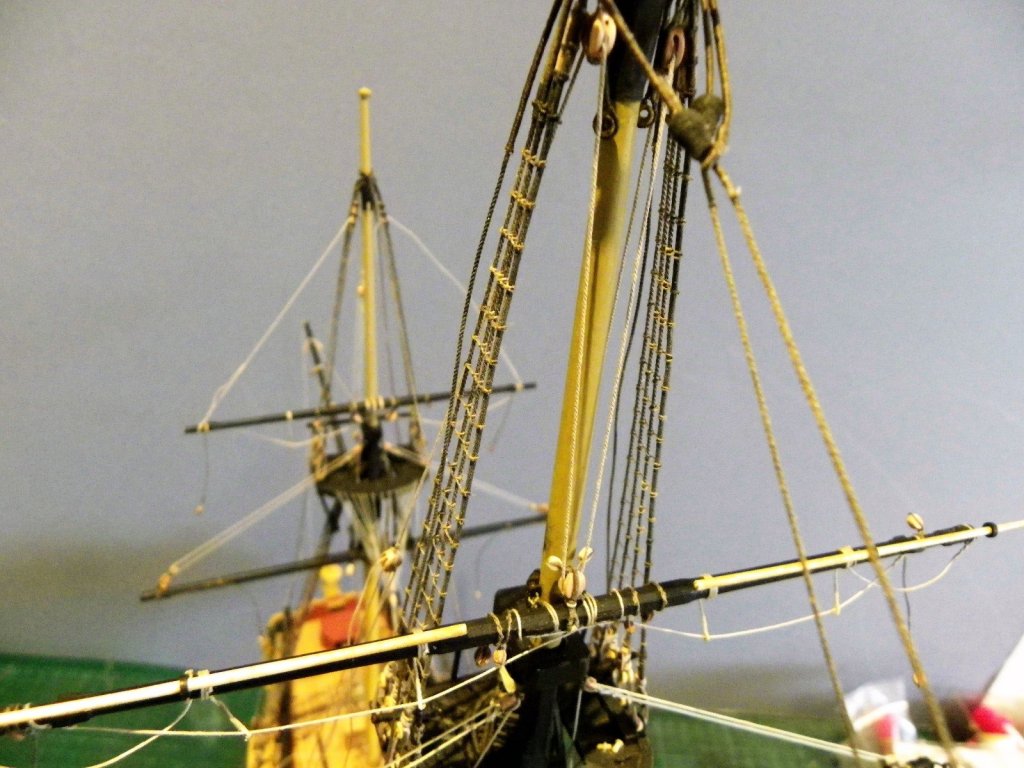
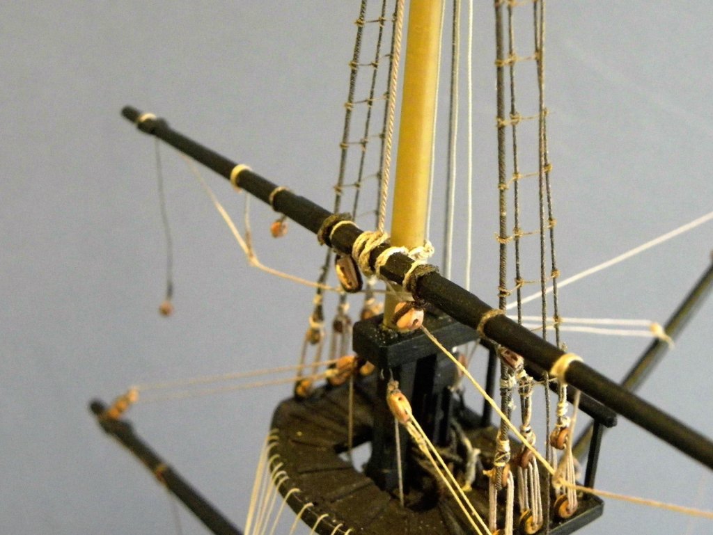
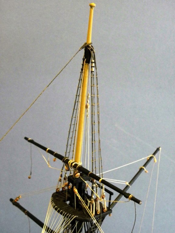
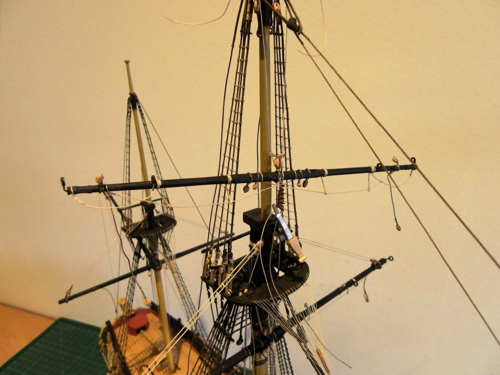
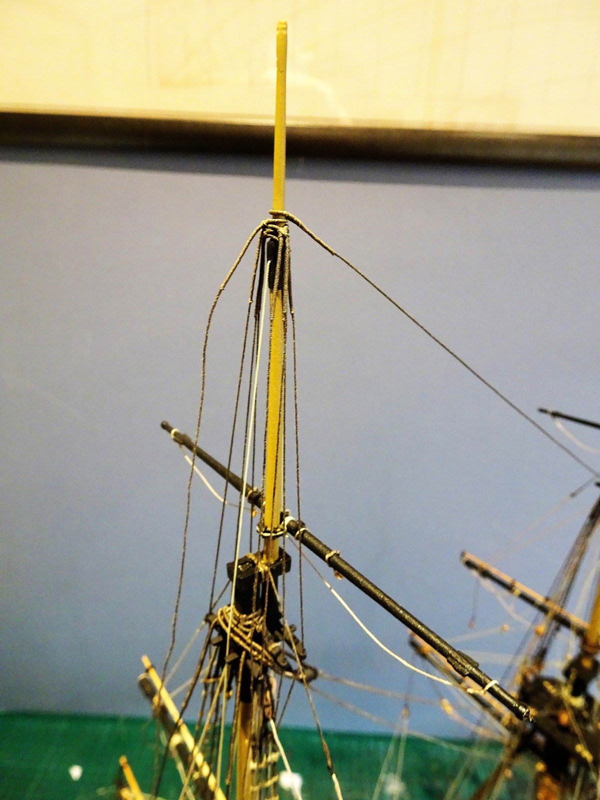
Main T'gallant Shrouds and stay There are two pairs of shrouds each side, the aft leg of the second pair extending down to the channels as the Main T'gallant backstay. T'gallant shrouds/Backstays - 2½ line (0.31mm) For the shrouds I used Syren 0.30mm line served with Morope 0.1mm line 20mm each side of the centre. The shrouds pass thro' the holes bored thro' the cross trees and are seized to the Topmast shroud futtock staves. I am very conscious during this task of the delicate nature of the crosstrees, a breakage at this point would be somewhat inconvenient. I firstly secured the centre shroud each side being careful not to misalign the mast, then the foremost shroud followed by the aft shroud. Light weights are hung from the shroud ends, which give the tension whilst the seizing is done. The backstay deadeye set up I will leave until later. Main T'gallant Stay 3" line (0.38mm) - Served over eye. Steel's description:- THE MAIN-TOPGALLANT-STAY reeves through a block fastened to the fore-topmast-head, has a thimble turned in the end of the stay, and sets up to a thimble in a span, made fast to the trestle-trees of the fore-mast, with a laniard cats-pawed to the top-burton-tackle, or a handspec: in small ships, termed a Spanish-windlass. For the stay I used Morope 0.4mm line. The stay eye was formed over a mast substitute and served before dyeing. Slipped over the masthead the stay runs forward to pass thro' a block (3.57mm) stropped to the Fore topmast head. This has a strop sufficiently long to keep the run of the stay clear of the Foremast cap. A thimble is turned in the end and the stay is secured by a lanyard to another thimble in a span which I had earlier attached to the Trestletrees of the Fore top. Note: Whilst the narrative in 17.6 of the ffm Vol.IV is correct, the associated Standing rigging plan Insert#2 is erroneous showing the run of this stay to the Foremast head instead of the Fore Topmast head. Rigging of the Fore T'Gallant followed the same arrangement, and was somewhat easier to do with a more open access. Here the yard is in place. The horses, clue blocks, and parrel were attached off the model; the parrel was simply slipped over the masthead and tightened up. The Tye can be seen passing thro' the sheave in the hounds. B.E.


- 366 replies
-
- 2
-
-
- pegasus
- victory models
- (and 2 more)
-
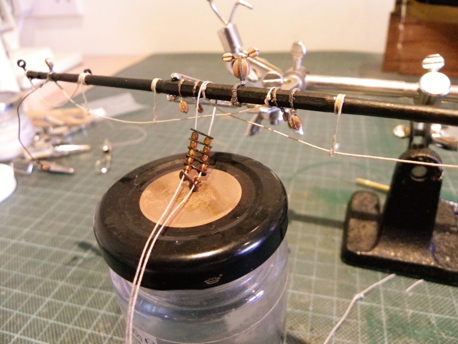
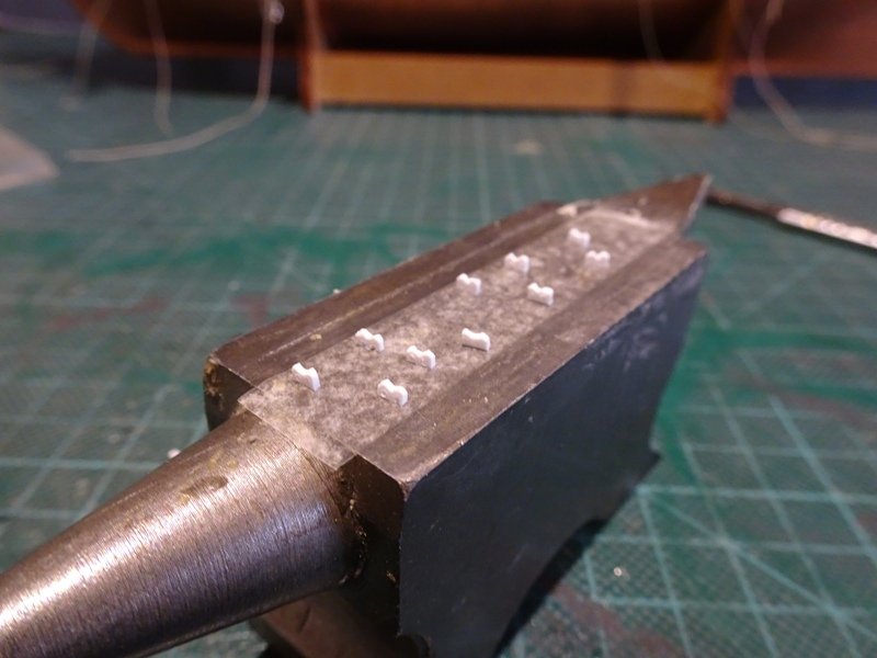
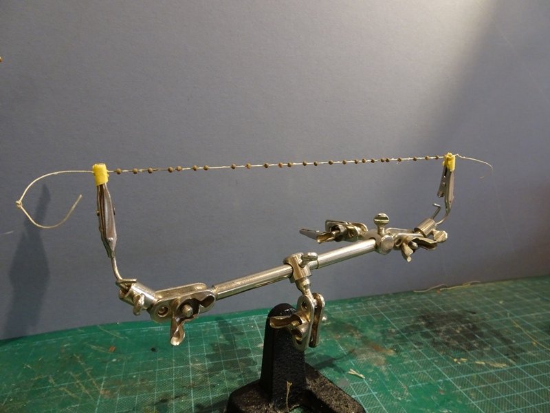
Fore and Main T'gallant yards As a break from Topsail rigging I have turned my attention to the T'gallant yards. There will be some lines that will require centre line belaying so they are best tackled now. Fortunately rigging to the yard is much simplified; Footropes (0.20mm)without stirrups, and only a couple of 2mm clue blocks. The same can't be said for the yard parrels which scale to a very small size. The ribs are 2.4mm in length, and less than 1mm wide, and 0.5mm thick at scale. I don't like to see oversize parrels on models, and most kit provided arrangements are oversize, so a little bit of head scratching to work out a strategy. I made the ribs individually out of Styrene strip 2.5mm x 0.75mm, forming the 'B' shape first, then drilling 0.4mmø holes, and then slicing them off the length. Finally the ribs were painted black. There are six rib and ten trucks in two rows for each T'Gallant yard on my Pegasus. At this very small scale making them out of wood was a non starter for me, too many failures, and styrene is an easy medium to work with. The trucks are tiny (2"ø (0.8mm) / 2½" (0.99mm) long) For my first attempt I used my smallest seed beads which being of a pretty pink colour required painting. Not a success when finished they looked twice the scale size and were discarded. For my second attempt I used micro brass tubing of 0.8mmø cut into 1mm lengths. The difference can be seen in the above photo. Rigging upper yard parrels is a tiring business on the arms if it is done on the model, but with the T'gallants I think I can rig them off the model and slip them over the T'gallant masthead. and then give them a final tightening. A suitably sized paintbrush handle acts as a surrogate T'gallant mast. The Tye and Halyard With the yard in place, (I did fit a small pin to assist fitting), the Tye is attached to the yard. The Tye is led up thro' the sheave at the hounds, and a 2mm block is spliced in. 0.25mm Morope was used for the tye. For the Halyard 0.1mm line is used, the standing end is seized to the Tye block strop, and a tackle is formed with a 2mm block and hook arrangement fitted to an eyebolt clenched to the starboard Trestletree in the Maintop. So far so good: This is what Steel has to say:- THE TYE reeves through the sheave-hole in the hounds of the topgallant-mast, and clinches round the yard in the slings or middle; then has a double-block turned in the lower end, and is connected, by the haliards, to a single-block lashed to the after-part of the lower trestle-trees, under the top: the lower end of the haliards belays round the cross-piece of the bits abaft the mast. This presents me with something of a problem, I simply don't have access to the bitts aft of the Mainmast to belay the Halyard. However, this is a light line so as a practical alternative I belayed the fall to the Quarterdeck rail. Not easy to get clear photo's. but the halyard fall can be seen hitched to the centre of the rail having passed thro' the sheave. Even this was no easy task to complete as the tweezers constantly snagged the existing rigging. The end will be tidied up later. The Fore T'gallant halyard will be a much easier task to complete. Before I proceed further with the yard rigging I have to attend to the T'gallant shrouds and Main T'gallant stay which will be covered in the next update. B.E.


- 366 replies
-
- 2
-
-
- pegasus
- victory models
- (and 2 more)
-
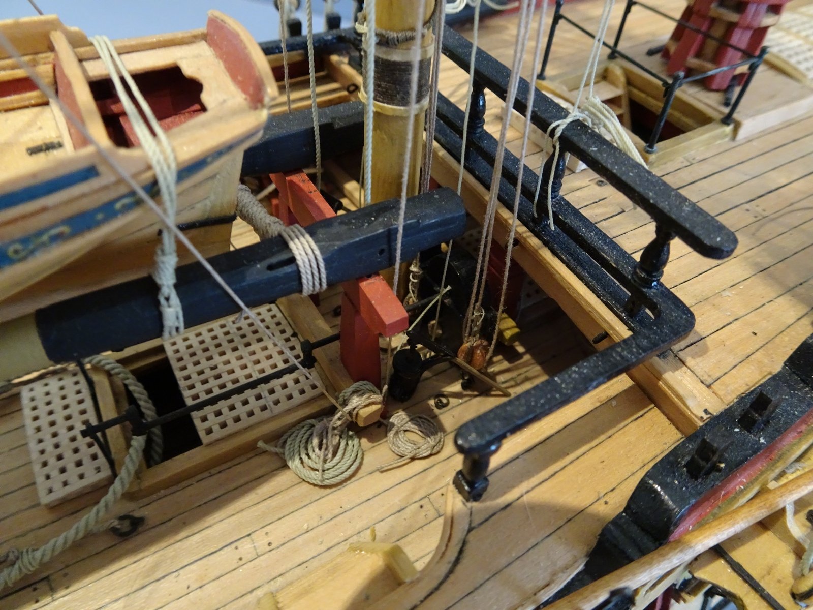
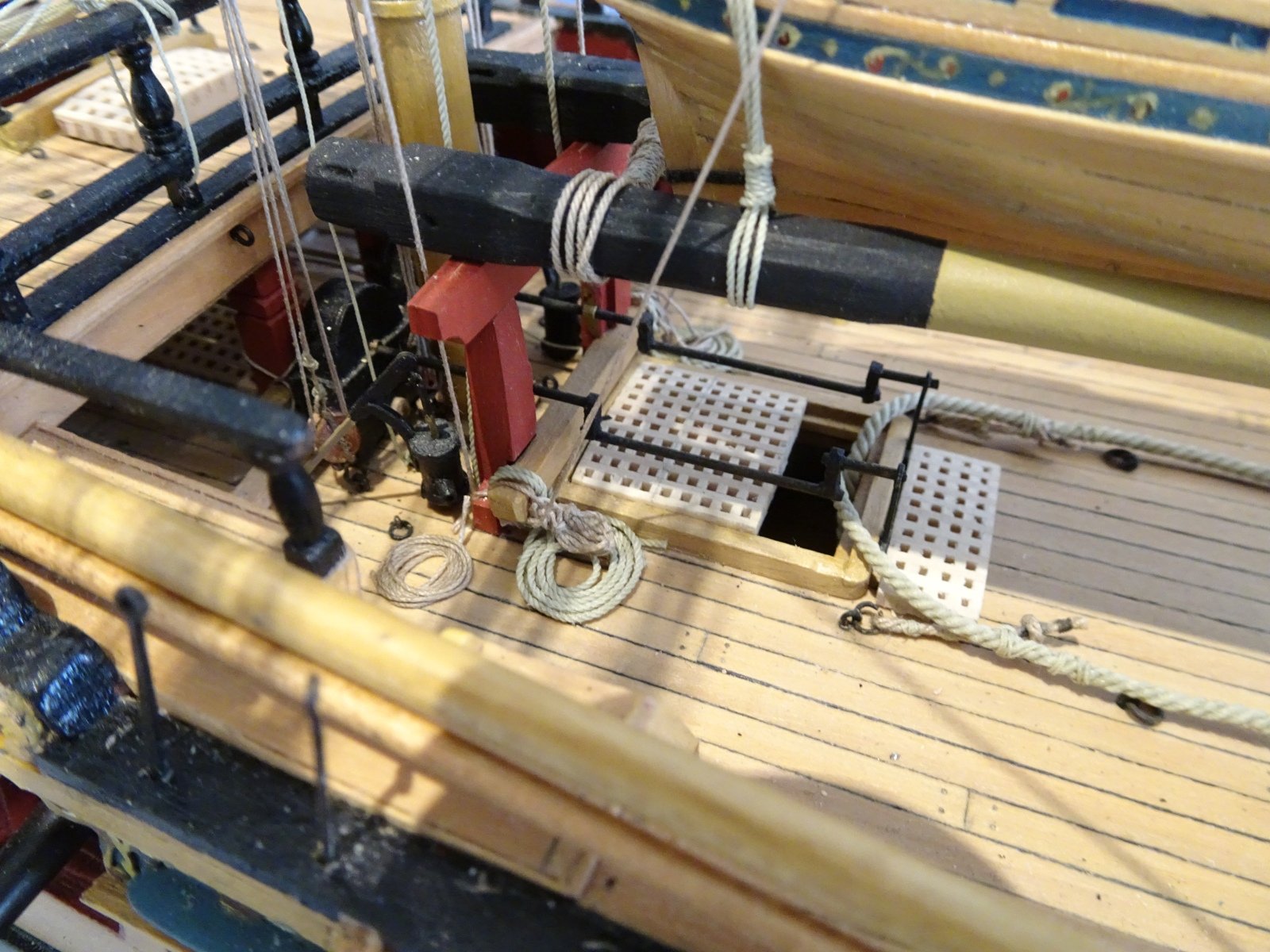
Continuing the Rigging of the Topsail Yards. Topsail Clue and sheet lines. Main Topsail Yard One of the trickiest rigging exercises is fitting the combination of Clue and sheet lines to the Main Topsail Yard. Both lines link together and belay in the area of the crowded Main mast foot. The sheet line in particular, a fairly substantial 4½"circ line scaling to 0.57mmø, has to feed thro' the inner sheave of the Main Topsail Bitts to belay. Those working with the Pegasus/Fly kits will soon come to appreciate the advisability of ensuring the sheave holes in the Bitt uprights are sufficiently large to facilitate feeding the sheet thro' from aft. There is only a space of 15mm between the Bitts and pump covers, the Qtr deck rails impede access from above, and to further complicate matters other tackle is already in place. I fiddled around with this for an entire afternoon with much under the breath muttering. I liken the process to threading an out of focus needle when you can't see the eye. When the end eventually does appear thro' the sheave, what a relief, but ahead lies the problem of belaying the line where there ain't much to belay to. I used Morope 0.6mm line for the sheets, the standing end is knotted and passed thro' the strop of the clue block, before feeding thro' the large yard block at the yardarm, running behind the yard to pass thro' the Quarter block, and down to the bitts. One of the benefits of the sheets is that they hold down the Topsail yards against the pull of the lifts and bunts. Main Clues 8" blocks (3mm) 2" strops (0.25mm) 2" line hitched to yard 2' outside clue blocks. I used Morope 0.25mm) The hitched line passes thro' the clue block, up thro' the yard block, down thro' the top to belay at mainmast foot or Qtr deck rail opposite mast. This is a little easier to attach, and for expediency I simply knot it thro' the eyebolt at the mainmast foot without any fancy lashing. Fortunately it won't be seen with the elmtree pumps in place. A lot of lines running down, a relief to complete this item of rigging. Fortunately access to the Fore Topsail sheets is easier. Using 0.6mm Morope, the 4½" line is belayed to the Fore Topsail sheet Bitts thro' the inner sheave. The Fore topsail clues also belay to the Fore Topsail Bitts on the cross piece. Fore Topsail clues rigged, the sheet knot is held by the strop of the clue block. I have to take rigging these lines very slowly, opportunities for snagging and fouling abound with the increasing number of lines already rigged. Fore and Main topsail buntlines The buntlines (2" line) are knotted and run thro' lead blocks stropped to the Topsail Tye block at the centre of the yard. From here they lead up to 7" blocks stropped to the middle Topmast crosstrees, and down thro' the top to belay at the lower shrouds opposite the mast. The biggest issue with these is getting the lines to run cleanly down to the belay without fouling the multitude of lines passing thro' the top. Just when I think I can belay to the shroud cleat, I follow the line back upwards and find the lines are twisted around other rigging lines, always worth a final check before tying off. Pegasus is now starting to look like a rigged ship. Mizen Topsail Clues, Sheets, and Bunts. Clues 1½" (0.20mm) line 5" block (2mm) belayed to eyebolt at foot of Mizen Mast. Sheets 3" line (0.4mm) belayed to forward cleats on Mizen Mast I have used Syren 0.20mm line for the clues, and 0.4mm line for the sheets. No bunts have been fitted on this yard. B.E.


REDMSW.thumb.JPG.7e19e4234021728df544366def9760ac.JPG)


- 366 replies
-
- 3
-
-
- pegasus
- victory models
- (and 2 more)
-
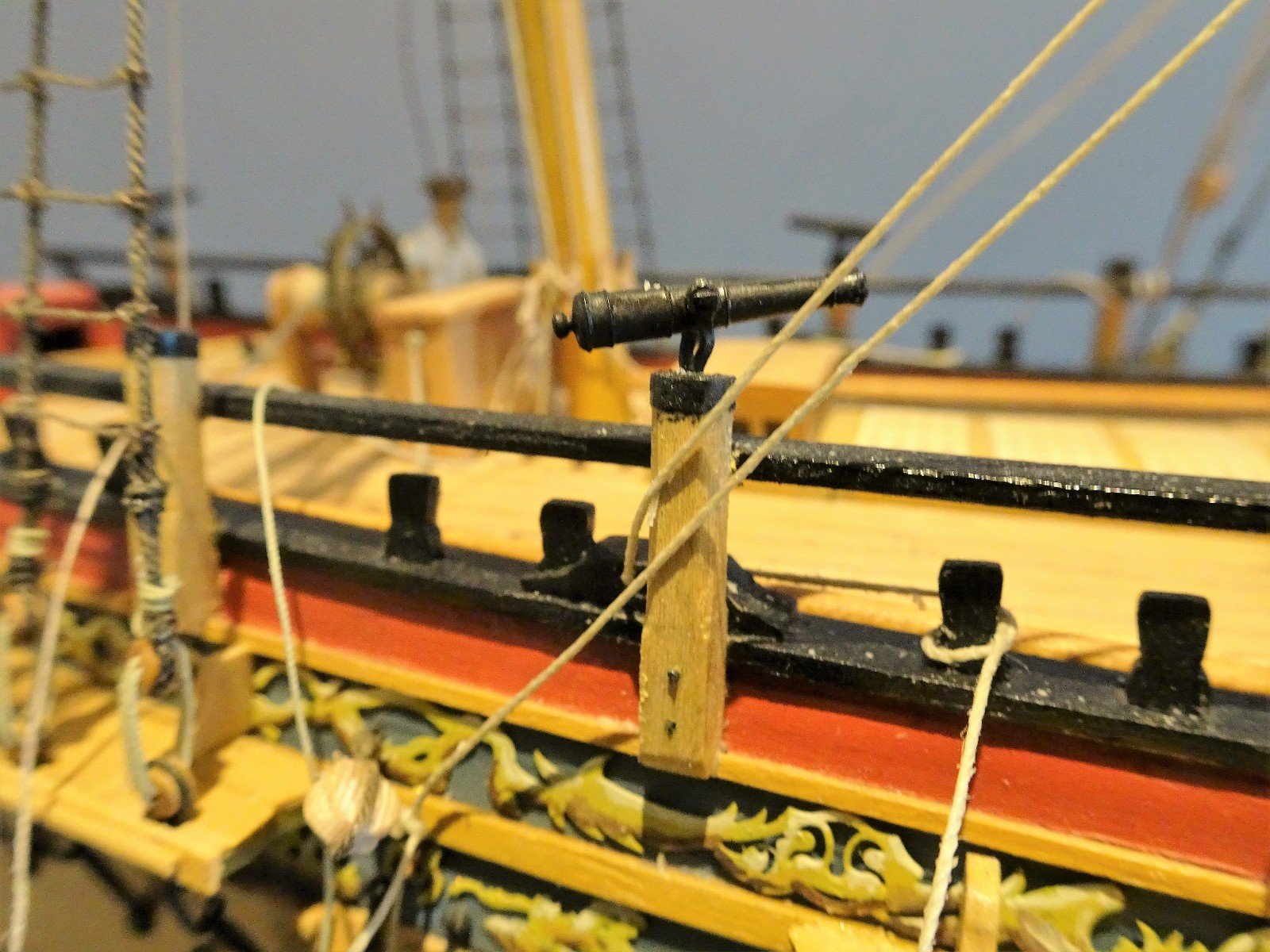
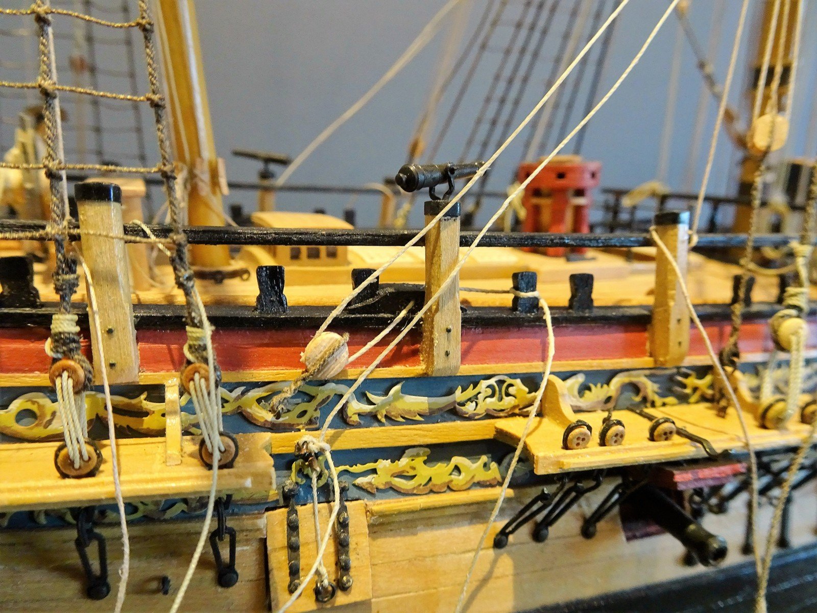
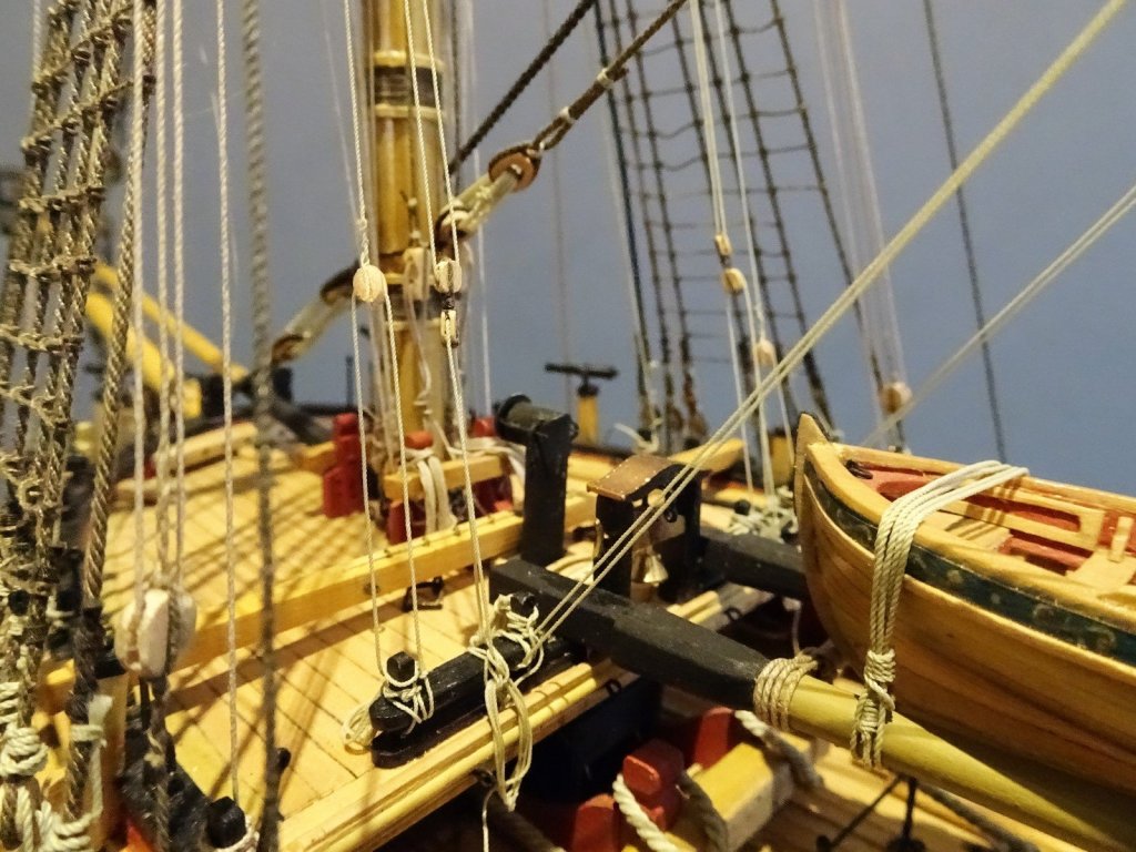
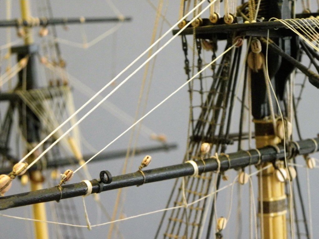
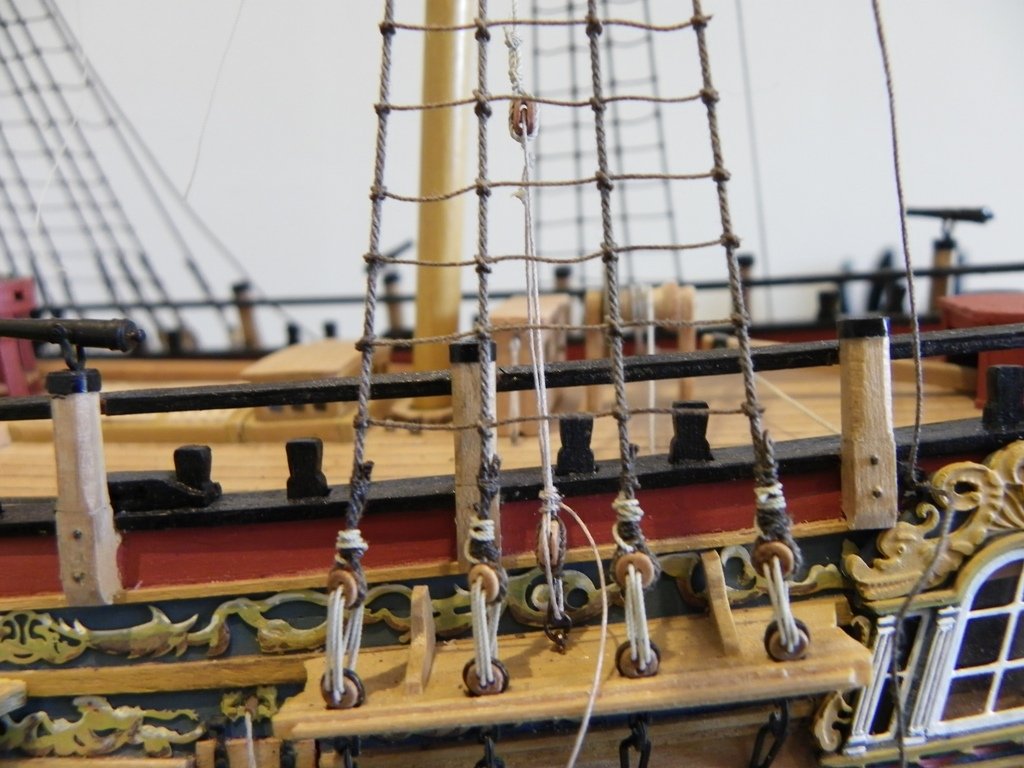
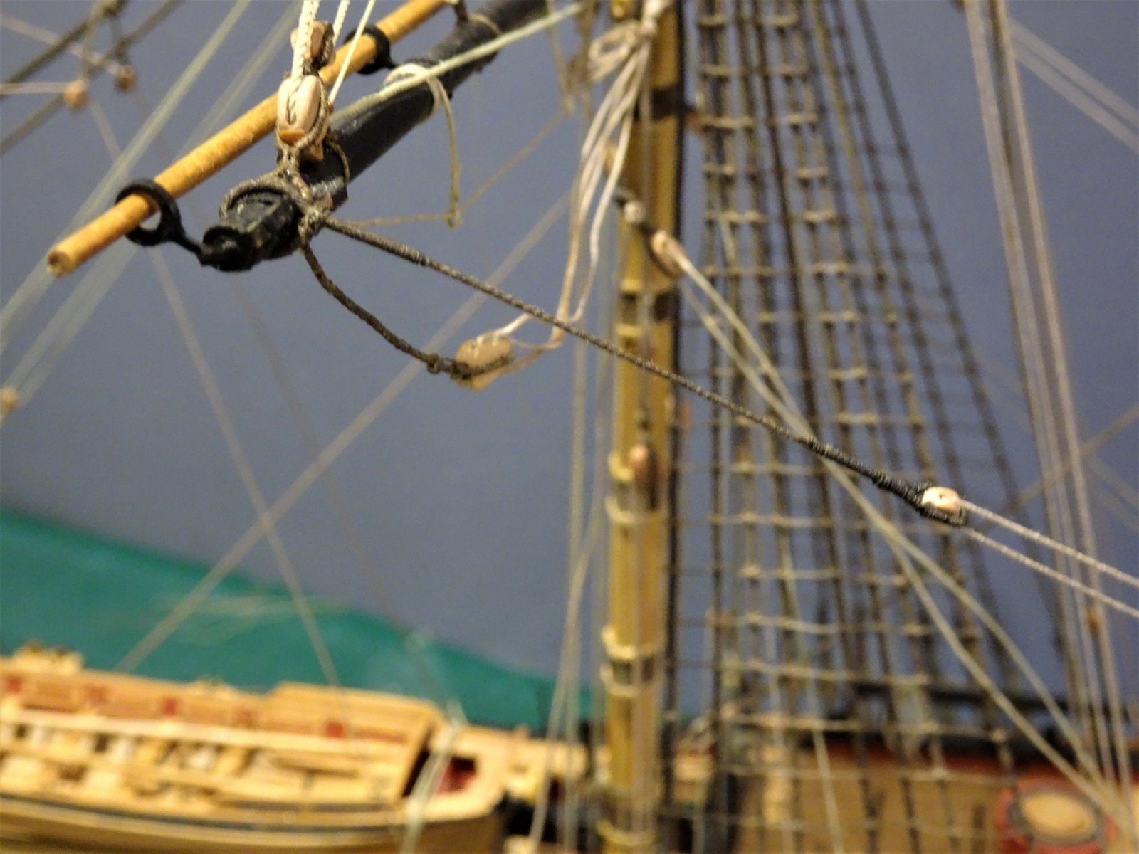
Main Brace Falls The Brace falls are of 2½" line (0.31mm) Steel says:- MAIN-BRACES reeve through a single block in the pendent; the standing part makes fast with a clench round an eye-bolt in the upper part of the quarter-piece; the leading part reeves through a snatch-block close aft upon the gunwale, and belays round a cleat on the inside. SPAN FOR MAIN-BRACES has two legs, with a thimble spliced in the end of each leg, which reeves the standing and leading part of the brace, and the span makes fast with a half-hitch, and the end seized up round the mizen-shrouds. Note: The span referred to above had not been introduced at the time period of Pegasus. Rigging the Main Brace is a little easier than the Fore Braces. The Brace Pendant, served each end, is slipped over the yard arm. I settled on 55mm for the length of the pendant excluding the strop, which is just over one third of the yard arm length. Access for belaying is much more open. The eyebolt for the standing end of the brace fall is fixed to the side. The line then passes thro' the brace pendant block, down thro' the fixed block (forward sheave) to belay at a timberhead. I have opted for the fourth timberhead from aft, as this is clear of the steering lines. Again, no securing of the belay at this point, so I can slacken them off for access. B.E. 21/11/2016


- 366 replies
-
- 2
-
-
- pegasus
- victory models
- (and 2 more)
-
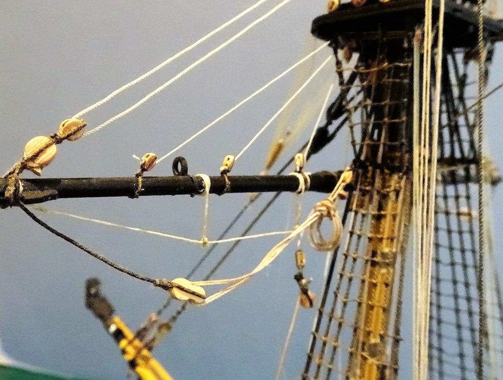
Yard brace pendants The ffm makes reference to the Lower Yard Brace Pendants being of served line (18.20 Vol IV), but makes no reference to the Brace Pendants to the Topsail Yards being of served line (19.19) This is what Steel has to say:- BRACE-PENDENTS have an eye spliced in one end to the size of the yard-arm, and a single block in the other end. The splices are served over with spun-yarn. PREVENTER-BRACE-PENDENTS are spliced through the strap of the brace-pendent-block; served with spun-yarn over the splice; and are left the length of the service of the splice and length of the eye longer than the brace-pendent, with an eye spliced in the other end to the circumference of the yard-arm. My reading of this is that the serving covers only the block and eye elements of the brace. The Brace Pendants fit last over the yard arms and butt against the yard tackle pendants. 8" blocks ( 3.17mm) I am using Pear wood blocks. 3½" line (0.44mm) I am using Syren 0.45mm line served with 0.1mm Morope for the spliced areas. I have gone with a pendant length of one third of the yard length. A little fiddly this, as the served line has to go around the fairly small block and have an eye formed in the other end, likewise served. The eyes then simply fit over the yard arm. So far so good. Fore Brace Falls The Brace falls are of 2½" line (0.31mm) According to Steel FORE-BRACES reeve through the pendent-block; the standing parts make fast round the collar of the main stay, on each side, with a hitch, and the end seized. The leading part reeves through a single block, lashed on each side the main-stay-collar, close up to the rigging, then leads down, and passes through a sheave-hole in the bitts, at the fore part of the quarter-deck, and there belays. Brigs lead the same. This differs from the ffm suggested arrangement - (2) 9" single blocks (3.57mm) on a span clove hitched around the Main stay below Crowsfeet tackle; Standing part hitched to Main stay below the Mouse, fall to Main sheet bitts, outer sheave, to belay at crosspiece. There are a number of time related arrangements referred to by Lees for rigging the Fore brace falls, all pretty similar with effectively minor shifts in position for the standing and running lines. This time I am going with the ffm arrangement, not least because using the Steel arrangement involves trying to feed the running end of the line thro' the bitt sheave from aft, a near impossible task now. The kit instructions show the fall passing thro' lead blocks attached to eyebolts adjacent to the Main hatch before belaying at the bitts, this also is a method noted by Lees. To rig the falls the two stay blocks are fitted in a span, (mine had a finished o/a length of 64mm) before hitching around the stay. The standing line ends are clove hitched also around the stay just below the Mouse. The lines run down to the bitts; managed to get the ends thro' the sheaves but there's only a short extension of the cross piece to the bitts and very little room to belay. Other stuff also has to go here according to the ffm. The biggest concern being the Main Topsail sheets. This is an untidy stage of the build with an increasing number of loose ends as lines are rigged but not tied off. This shot shows my approach to the Braces; I aim to get a slight degree of sag to impart 'weightiness' to the lines. I've a way to go yet before I achieve the result I'm after, and I won't tie off the running end at the bitts for the present. I will next look at the Main Brace Falls. B.E.
.thumb.JPG.567c82eecefa46af504ea21f5e50218a.JPG)

- 366 replies
-
- 2
-
-
- pegasus
- victory models
- (and 2 more)
-
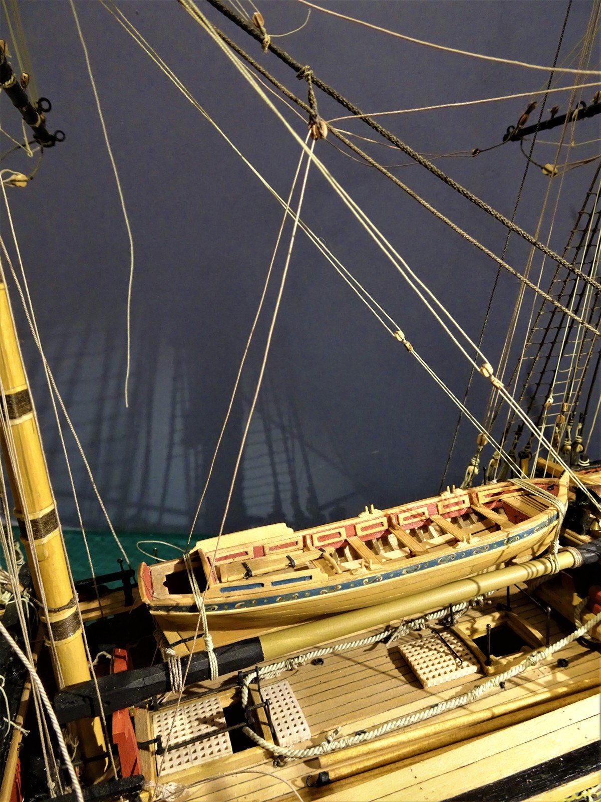
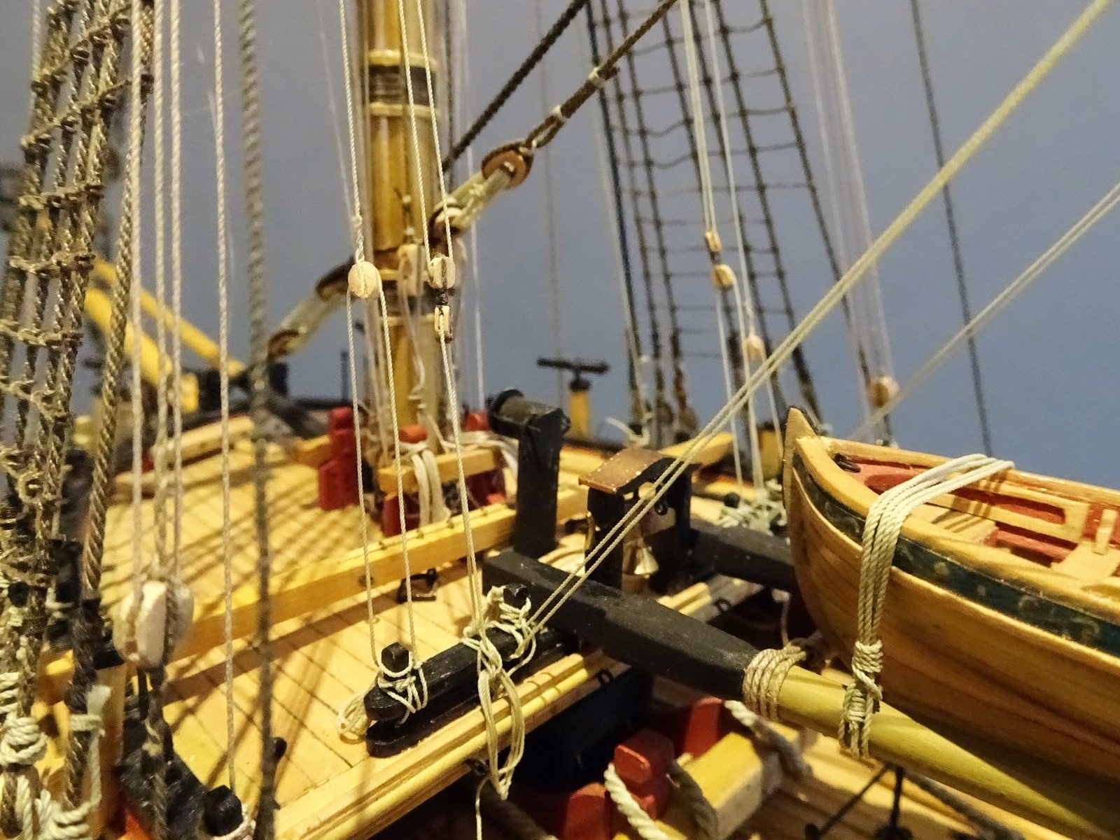
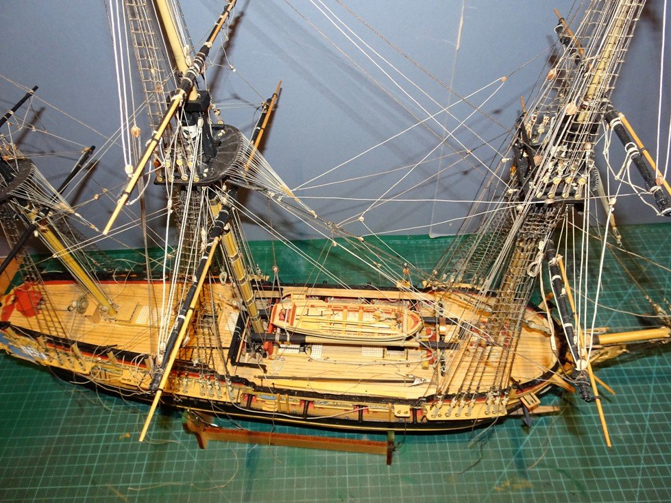
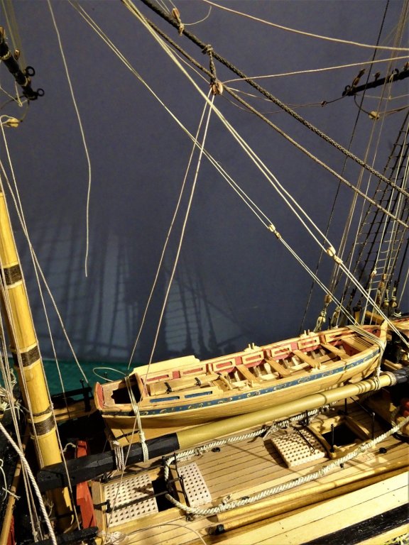
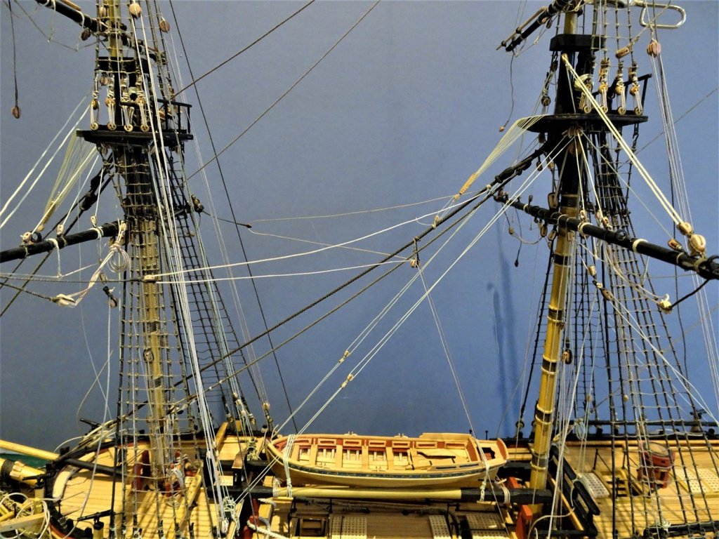
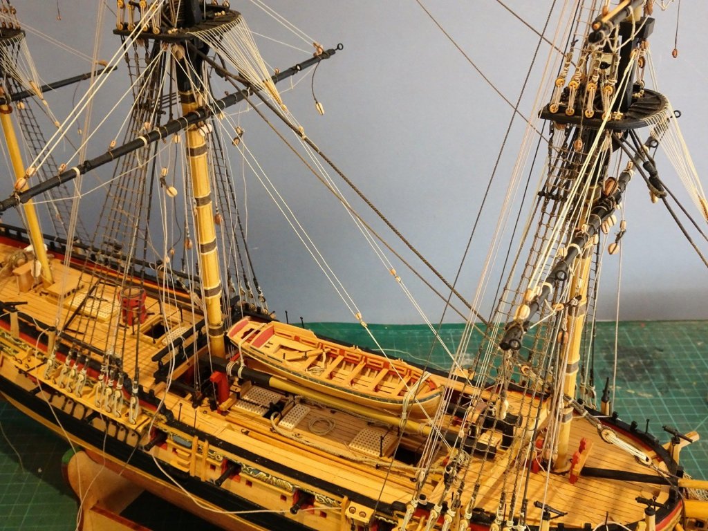
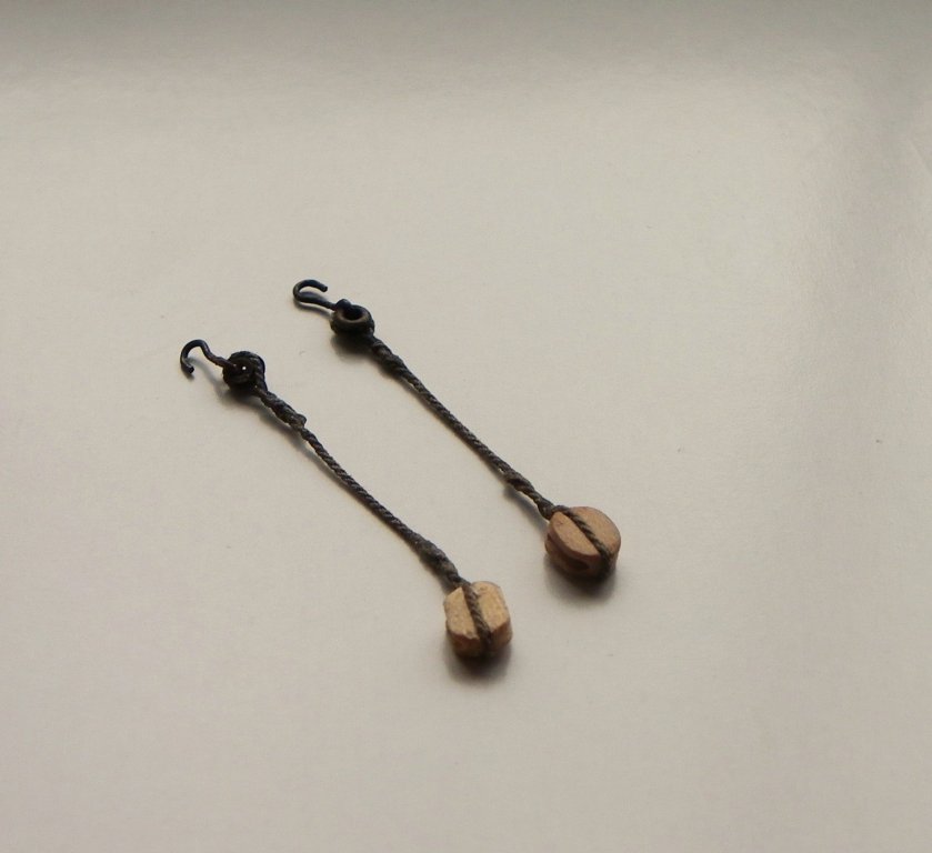
Yard Tackle Pendants and falls I don't think the kit includes these as part of the rigging suite, and apart from the pendant itself, the tackle may not be shown on a bare stick model. However, they are an important item of rigging, and I like to fit them. There are various ways to display the yard tackle pendants but I like to have them hooked to the futtocks with a degree of slack in the tackle line. Lees has a good drawing of the Yard tackles in his book (p71) and there is a photo of the Medway 1742 (NMM) with the tackles loosely attached to the futtocks. This is the look I like, but with perhaps slightly less slack in the tackle. NMM model of HMS Medway 1742 These are not easy to get to hang naturally, and the use of diluted pva and small weights are necessary to give them a 'weighty' look. The tackle falls consist of 2½" (0.3mm line). A 9" single block (3.57mm) is stropped with a hook at lower end of the fall. The LT block and Pendant had previously been attached to the yard arm outside of the horses. The Standing part is attached to the strop of the block, and leads thro' the pendant block, I allowed about 700mm of line for each tackle fall, and the excess line was coiled close to the block and hook at the Futtocks. I have yet to fit the Tricing lines that support the LT block and the tackle block at the other end. I will next attach the lower Fore and Main Yard brace pendants. B.E. 13/11/2016
.jpg.43c827f58f7e2f2044c4115470e9b014.jpg)
- 366 replies
-
- 2
-
-
- pegasus
- victory models
- (and 2 more)
-
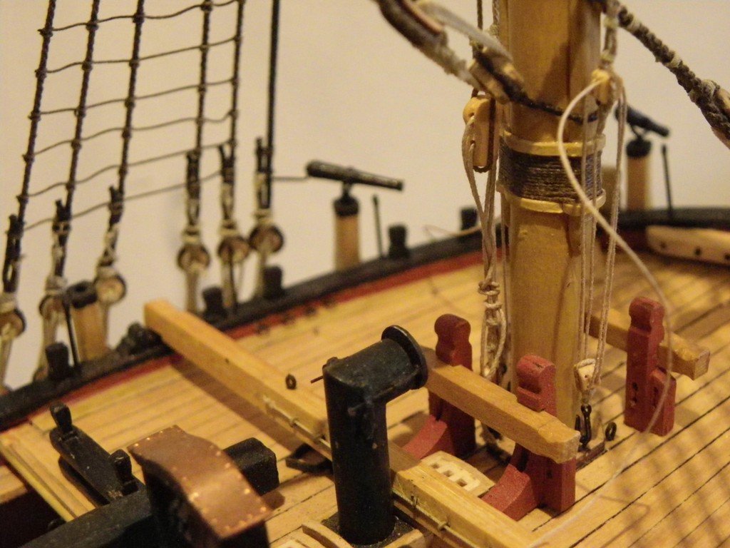
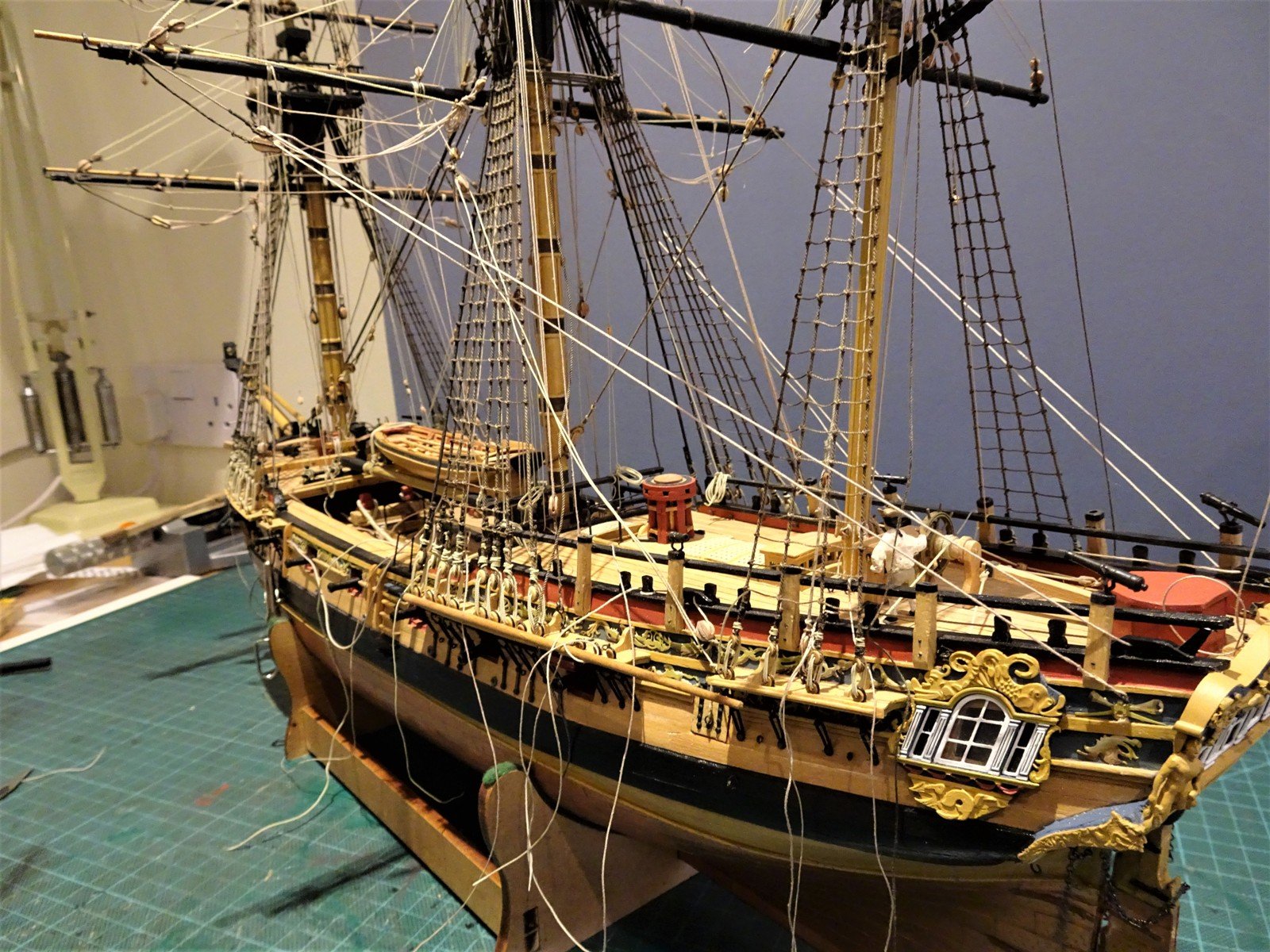
Checking the Main Sheets. I recently fitted the Main Course Clue Garnets, but before permanently tying off the running end at the Main Topsail sheet bitts, it is worth checking the lead for the Main Sheet. The running end passes thro' the outer bitt sheave and is secured. Checking the lead for the Main sheets. According to Steel:- SHEETS reeve through the sheet-block at the clues. The standing-part is seized to an eye-bolt with a thimble on the quarters. The leading-part leads through a sheave-hole on the same side under the half-deck, and belays to a range-cleat in the waist. The kit plans: Show the standing part attached to an eyebolt fixed to the rail above the aftermost gunport. The running end passes thro' a hole in the side above the standing part and belays to a timberhead. The ffm in Vol 11 shows the eyebolt for the standing end of the sheet directly below the fixed block ( 12.25 / 12.28) The standing part is hitched to an eyebolt in the ships side below the aft fixed block in the waist. 1¼" dia (0.5mm) 2⁵⁄⁸" in clear(0.94mm) The running end passes thro' the fixed block and belays to either a cleat or timberhead forward of the fixed block. According to Lees:- Standing part - eyebolt in side level with the Mizen mast Running part - thro' a lead block seized to an eyebolt above and just forward of the standing part, thro' a sheave in ships side just forward of the QD break and belayed to a cleat. My approach Looking at the run of the sheet line; to take it directly thro' the fixed block presents a very sharp angle which also binds the line against a swivel gun post. This arrangement looks awkward to me and for this reason the use of a lead block makes sense. The following pics show a trial run of the leads. The sheet block Run of Main Sheet. Having passed thro' the lead block the line passes thro' the fixed block atop the bulwark and belays to the timberhead. The sheet lines are a length of Amati line, the actual lines will be fixed later in the build. B.E. 10/11/2016
- 366 replies
-
- 1
-
-
- pegasus
- victory models
- (and 2 more)
-
Foreyard clue garnets 9" block(3.57mm) 2½" strop (0.31mm) Sheet block 14" (5.5mm) strop 4½" (0.57mm) Tack 5½" cabled line (0.69mm) These are part rigged now before the bunt and Leechlines get in the way of timber hitching the standing part of the clue line. Buntlines - Fore Course Steel:- THE FORE-SAIL BUNTLINES reeve through the leg and fall-block, and through a double-block at the aft part of the top; then through a double-block under the fore part of the top, and through the blocks upon the yard, and lead down the fore side of the sail, and clinch to the cringles in the foot. The fall reeves through the *leg-block; the standing-part makes fast round the breast-rail, and the leading-part through a sheave-hole in the breast-work, and belays round the rail. *Interesting that Steel writing in 1794 still refers to a leg-block when Lees states with some certainty that two single blocks stropped together replaced the leg-block in 1773. 2" line = 0.25mmø at scale (0.25mm Morope) Lines run from the inner yard block up thro' the inner sheaves of the fore and aft blocks beneath the top.* Thence thro' the upper of the fall block combo blocks, back thro' the blocks beneath the top (outer sheaves) and then to the outer yard block where it is passed thro' and knotted to secure. *Note: The Middle double blocks below the Fore top take the (two) Buntlines. The Outer double blocks take the Spritsail brace lines (inner sheave) and (Single) Leech line (outer sheave) Inner single block (2.5mm) takes the Sprit Topsail brace lines. Fore course Leech lines Steel:- LEECH-LINES reeve through the spritsail-brace-block, under the top, then through the block upon the yard, and the standing-part makes fast with a clinch to the upper bowline-bridle; the leading-part then reeves through a double-block, at the aft part of the top, and upon the forecastle. Steel doesn't mention any use of a whip in relation to the Leech fall as he does with the buntlines but Lees does. I can't imagine that the system would differ from the main course so I have fitted a block to facilitate the Leech falls as I did with the Main. The Leech line belays to the Belfry rail, with the running part also passing thro' a sheave. The whip fall belayed at the Belfry rails; the outer one is the Leechline, the centre one the Buntlines, the inner ones the fall to the Main course buntlines. B.E. 09/11/2016


- 366 replies
-
- 1
-
-
- pegasus
- victory models
- (and 2 more)
-
So Main Course Buntlines Mk11. I have dispensed with the leg and fall blocks and replaced them with two common singles stropped together, an arrangement that came into play around 1773. These lead forward down to the Foc'sle Belfry rail where they are belayed. The running end of the whip passes thro' the sheave in the rail, the standing part is timber hitched adjacent to it. When deciding on the position of the stropped together blocks, consideration must be given to hauling room. On a bare stick model with the buntlines hauled up to the yard block, the distance at least equal to the drop from yard to foot cringle must be allowed for. This positions them about half way between Fore and Main masts. Rigging them is one thing but getting the lines to lie without twist is entirely another. The trick is to orientate the blocks and stiffen the seizing between the upper and lower blocks. Lead of the Buntlines thro' the forward blocks beneath the top. (the outer line is the Leechline which runs to the Qtrdeck rail.) Trying to get the coils right on the rail is a frustrating exercise, tight space, springy Morope, high risk of snagging existing belays, and having to manipulate the lines with tweezers in each hand. Not quite there yet! B.E.

- 366 replies
-
- 1
-
-
- pegasus
- victory models
- (and 2 more)
-
Main yard clue garnets 9" block(3.57mm) 2½" strop (0.31mm) Sheet block 14" (5.5mm) strop 4½" (0.57mm) Tack 5½" cabled line (0.69mm) The ffm indicates the use of specialised shoulder clue blocks. but Lees says that the shoulder blocks were replaced with common blocks around 1773.(reason enough for me to not bother with making shoulder blocks) The ffm however in neither narrative or rigging plan indicate the rigging of the clue garnets on a model without sails. The kit plans do however include these lines. To rig the clue/sheet/ tack combo on a model without sails I have taken Lees approach. The strop of the clue block is passed thro' the strop of the sheet block, and the wall knot of the tack is passed thro' the clue strop to secure the three together. The standing part of the clue is timber hitched to the yard a few feet outside yard block. It is then taken down thro' the clue block combo back up thro' the yard block and down to belay at the Main Topsail sheet bitts thro the outer sheave. I have used Syren 5/32 blocks to match the yard blocks. A good time to fit these as access later will be difficult, even so temporary removal of the elmtree pumps is required to get to the bitt sheaves. Using the tack line to equalise the drop of the clue garnets these can be secured. The Tack leads forward thro' the Chesstree sheave and thro' the fixed block which sits beneath the Fore Channel stool, to belay on the large forward cleat. Tricky to get at now the brass decoration is in place, the end of the tack was stiffened with pva and then sliced at a long angle to provide a taper and is fed thro' the sheave. The tack cannot be secured at this stage as it will get in the way of replacing the Pinnace on its spare topmasts which were removed to allow rigging access. Trouble is completing the tack and sheets will leave no room to replace the Pinnace, and with the Pinnace in place, belaying the Main Tack and Fore Sheets will be made somewhat tricky with much reduced access. The situation is more complicated on my Pegasus as I have fitted gangboards between the QD and Foc'sle, not such an issue on those Swans without. Just remembered in time before I fit the leech and Buntlines I have yet to do the Futtock ratlines, the bunts and leeches would have seriously impeded the process. The vexed question of Main course buntline leads. There is an argument for leaving the bunts and leech lines off a model without sails, such as will be the case with my Pegasus, but I like to see them. For the purpose of a bare stick model the buntlines are knotted and pulled up taut to the yard blocks. Both the kit rigging plans and the ffm(22.9) indicate the buntline falls belayed at the Quarterdeck breast rail having passed thro' the yard blocks and the fore and aft blocks toggled beneath the Main top. Now this seems eminently practical, and an arrangement I followed. However, had I put my brain in gear and double checked, I would have seen that contemporary sources suggest differently. I would also have saved myself some considerable time in rigging the bunts. Buntlines rigged with Leg and Fall blocks, and belayed not without a little trouble to the Quarterdeck rail. This is what Steel has to say. THE MAINSAIL BUNTLINES reeve as for the fore-sail, and lead forward upon the forecastle THE FORE-SAIL BUNTLINES reeve through the *leg and fall-block, and through a double-block at the aft part of the top; then through a double-block under the fore part of the top, and through the blocks upon the yard, and lead down the fore side of the sail, and clinch to the cringles in the foot. The fall reeves through the leg-block; the standing-part makes fast round the breast-rail, and the leading-part through a sheave-hole in the breast-work, and belays round the rail. Lees says:- From 1680 main buntlines were taken forward being rove as follows:- one end of the buntline was made fast to cringle of the sail, the other end rove thro' a block on the yard, thro' a block under the fore part of the main top, thro' one sheave of a *shoe block, back up thro' another block under the fore end of the main top, thro' another yard block, and down to another cringle. Thro' the other sheave of the shoe block a line was rove, both end being made fast to the fo'csle rails. From 1773 two single blocks stropped head to head were used instead of shoe blocks. * Note Steel refers to Leg and fall blocks, and Lees to Shoe blocks. There is a difference. The description by Steel in relation to the Mainsail buntlines, referring to the Foresail leads, gives the impression that they should lead thro' the aft blocks beneath the tops before coming forward to lead upon the Fo'csle. Lees interpretation with the buntlines passing thro' only the forward block beneath the Main top before leading to the Foc'sle, makes more sense. So nothing for it but to unreove the buntlines and re-rig with the leads forward. This arrangement will cross the waist area, so I think it better to rig the Fore yard buntlines first, which do lead up thro' the blocks beneath the top aft and belay at the Foc'sle rail. This is not the first time I have been led astray by taking the ffm at face value. note to self: check all sources before committing. So having made a dog's breakfast of the buntline arrangements on the Maincourse, I'll see if I can make a better job of the Leech lines. Leechlines 2" line = 0.25mmø at scale (0.25mm Morope) Only one each side, again passing thro' the yard block and up thro' the outer sheave of the outer blocks beneath the top. The ffm indicates belaying the Main course leech lines to the Topsail Bitts, whereas Steel says..... LEECH-LINES reeve through the block upon the yard, and the outer end makes fast with a clinch to the upper bowline-bridle. The leading-part reeves through the double-block at the forepart of the top, and through a double-block at the aft-part of the top; a single block is turned into the lower end, and a whip-fall reeved through it. The standing-part makes fast to the breast-rail, and the leading-part through a block under the breast-rail, and belays round the rail. Given the far more difficult belay to the barely accessible Topsail bitts, I have opted for the rail belay with a whip-fall/single block arrangement. The line passes down thro' the lower shrouds, the whip and fall feeds thro' the block and the standing end is timber hitched to the rail with the running end passing thro' the sheave in the rail upright to belay. A needle file is used to add some resistance to the coil during the belay process. B.E.

- 366 replies
-
- 1
-
-
- pegasus
- victory models
- (and 2 more)
-
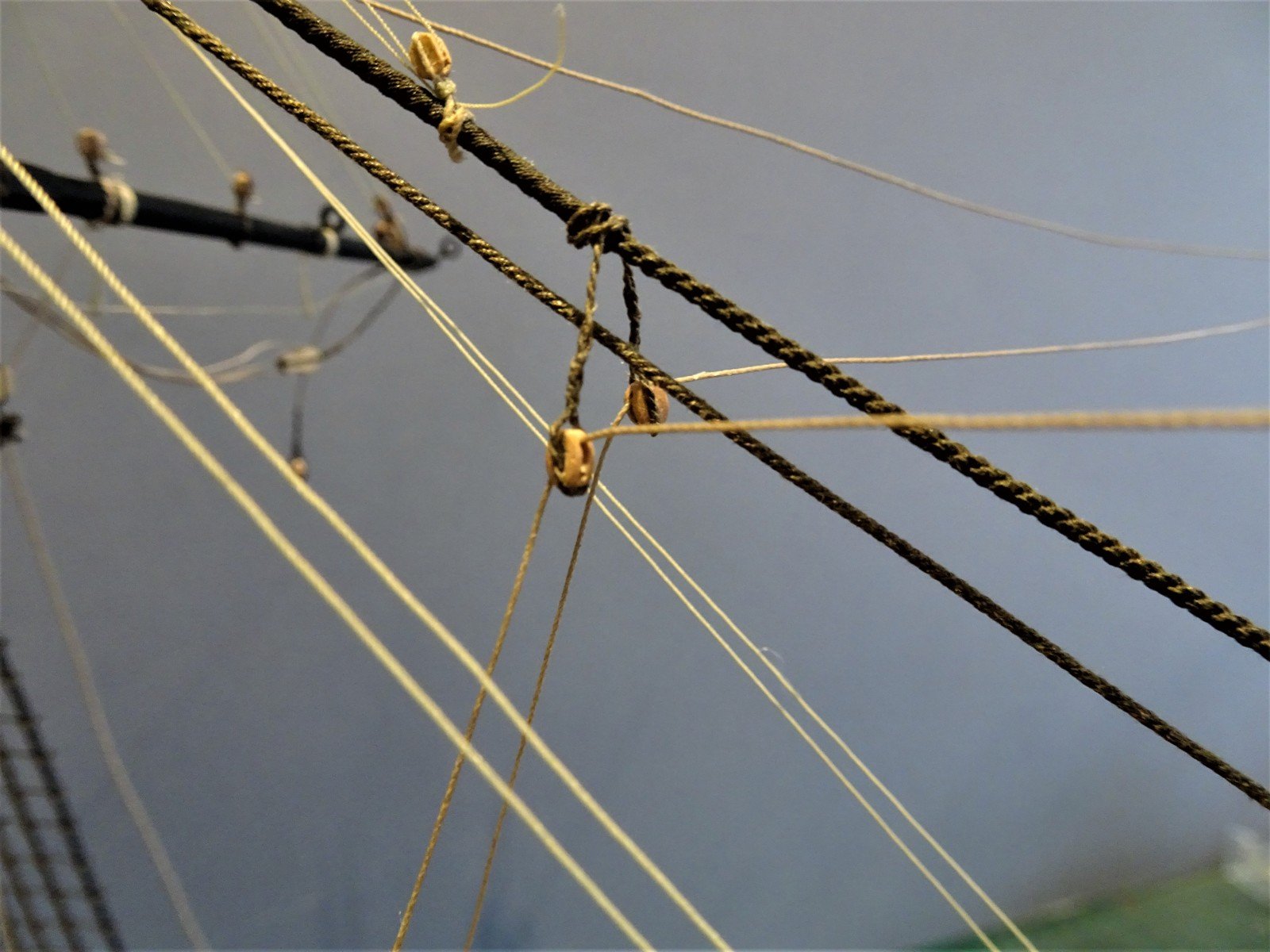
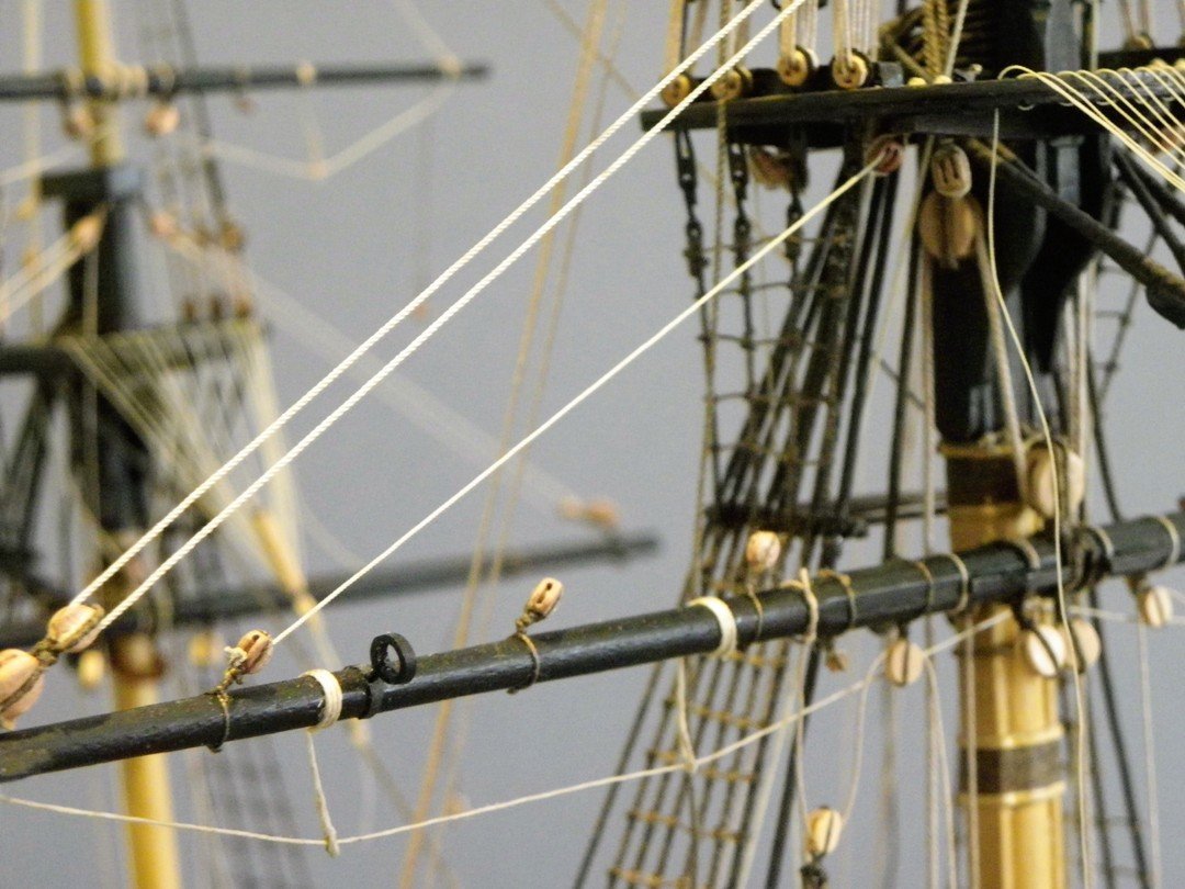
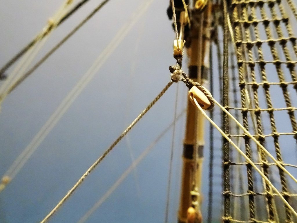
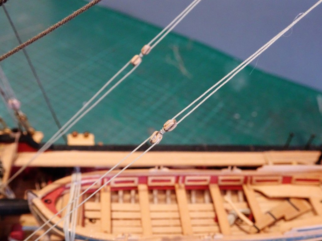
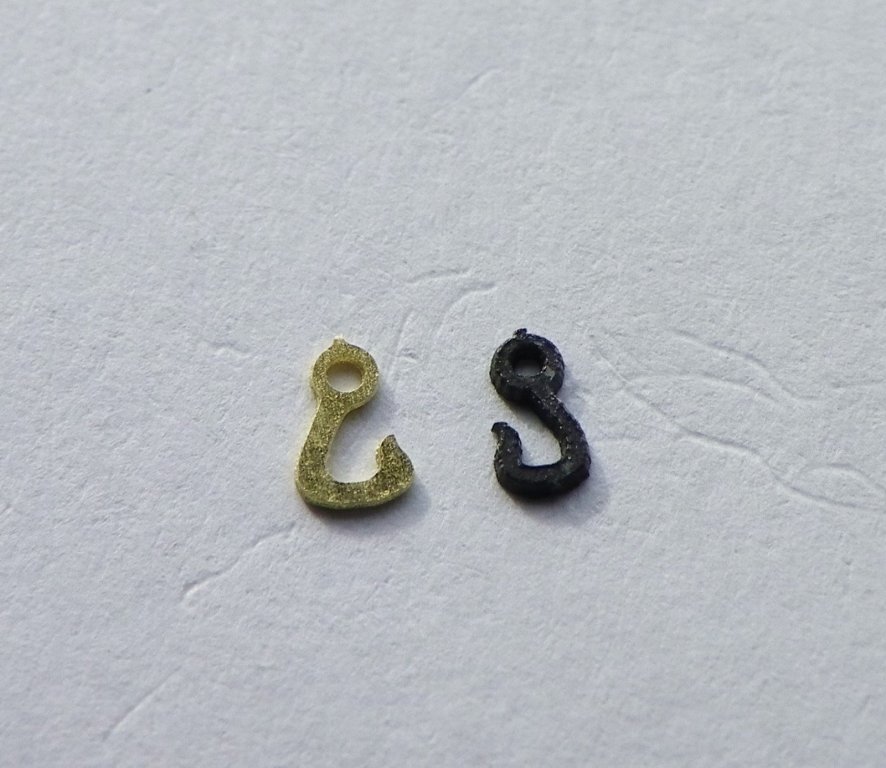
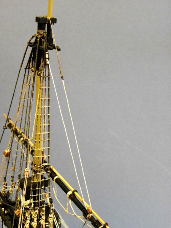
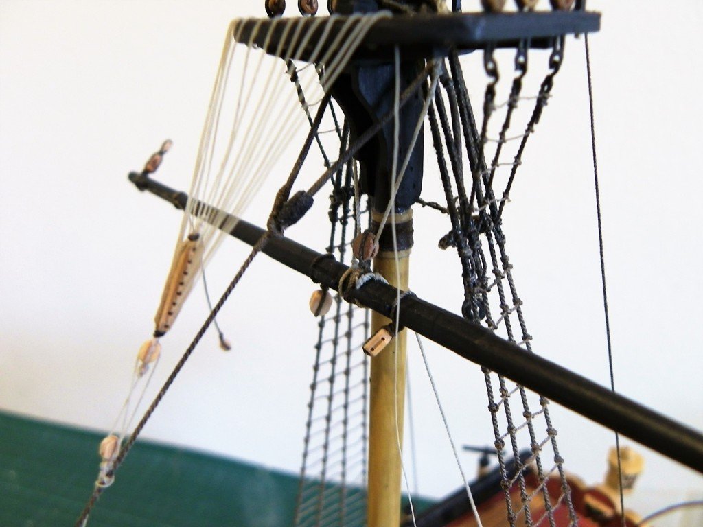
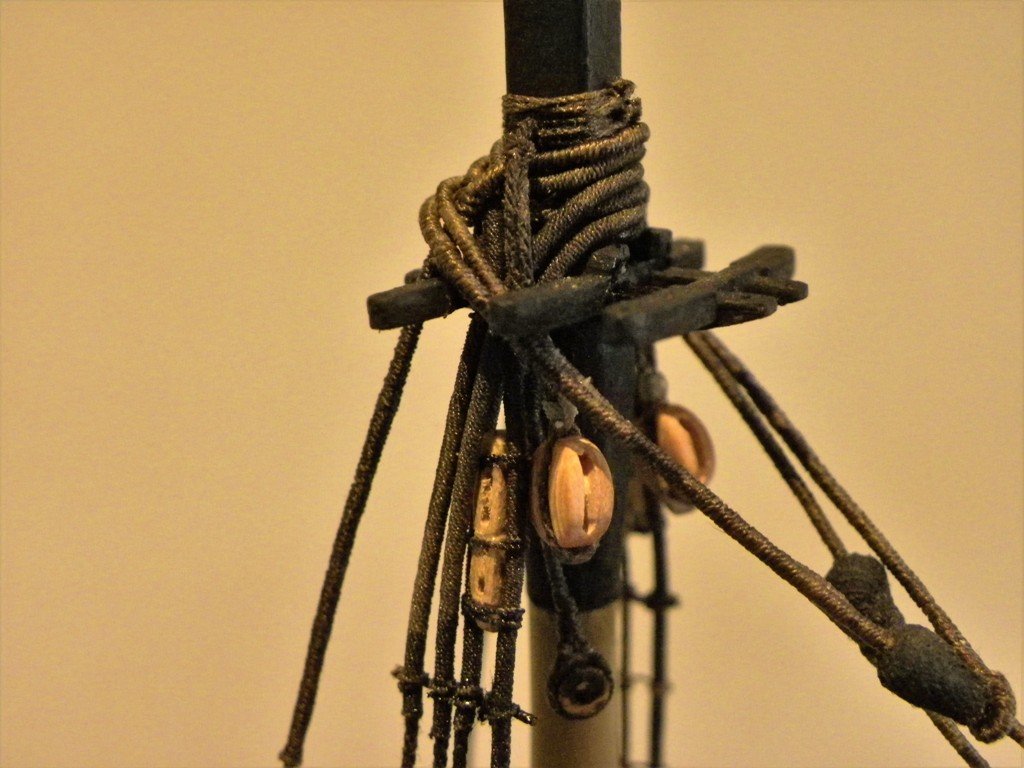
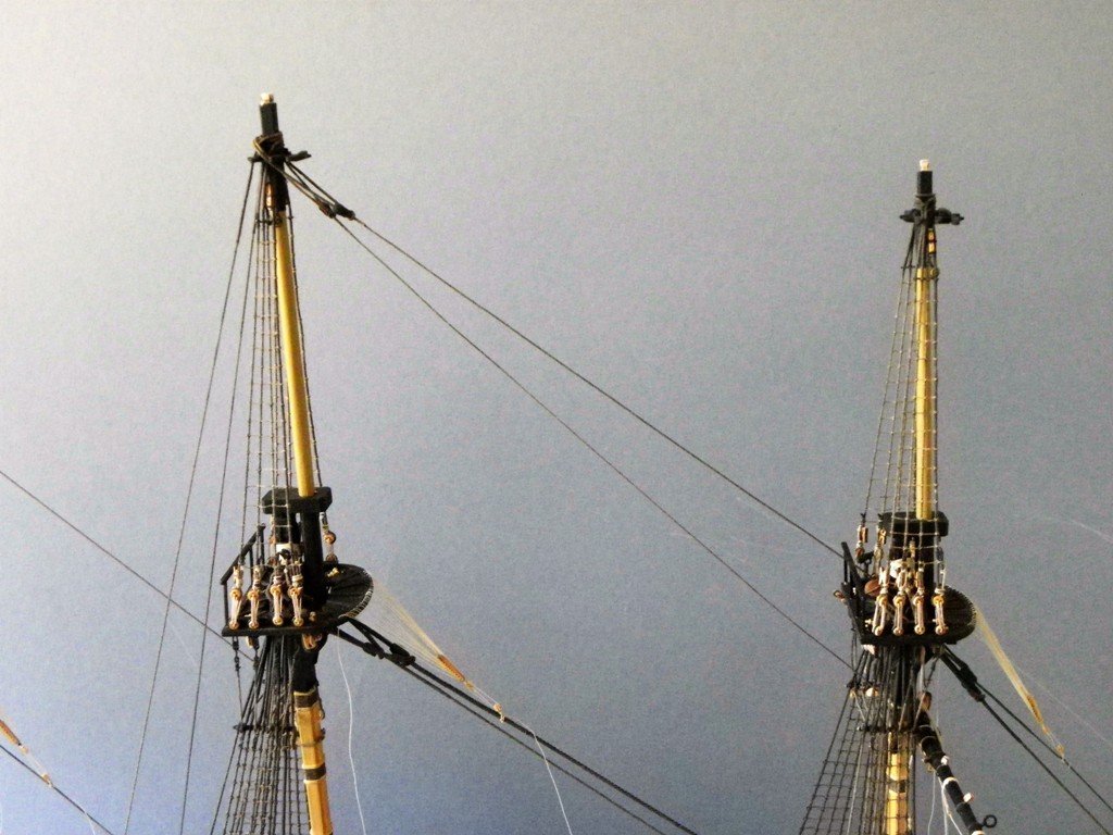
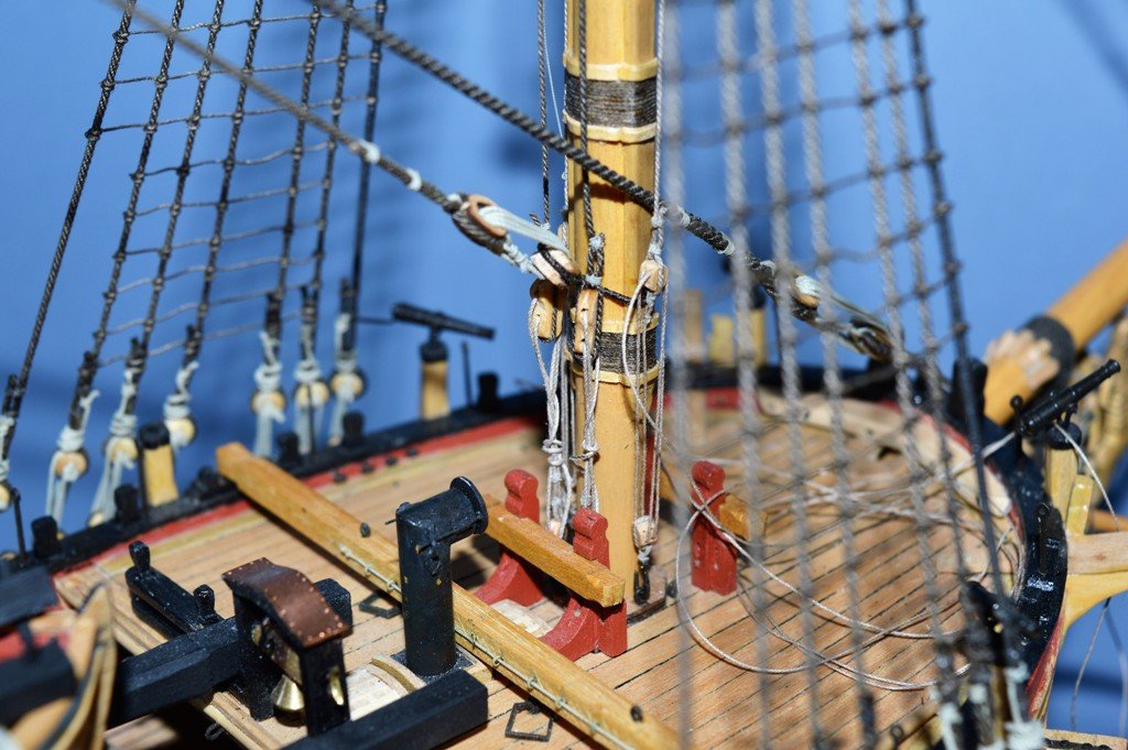
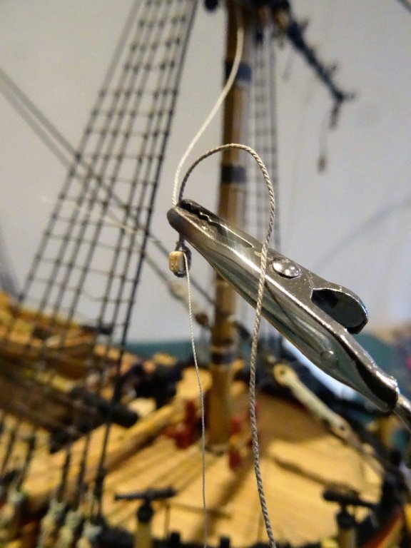
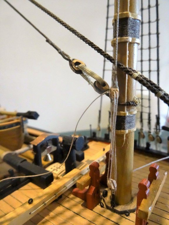
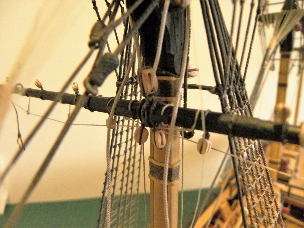
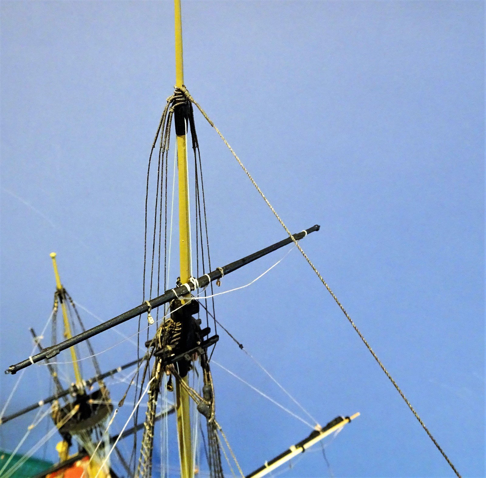
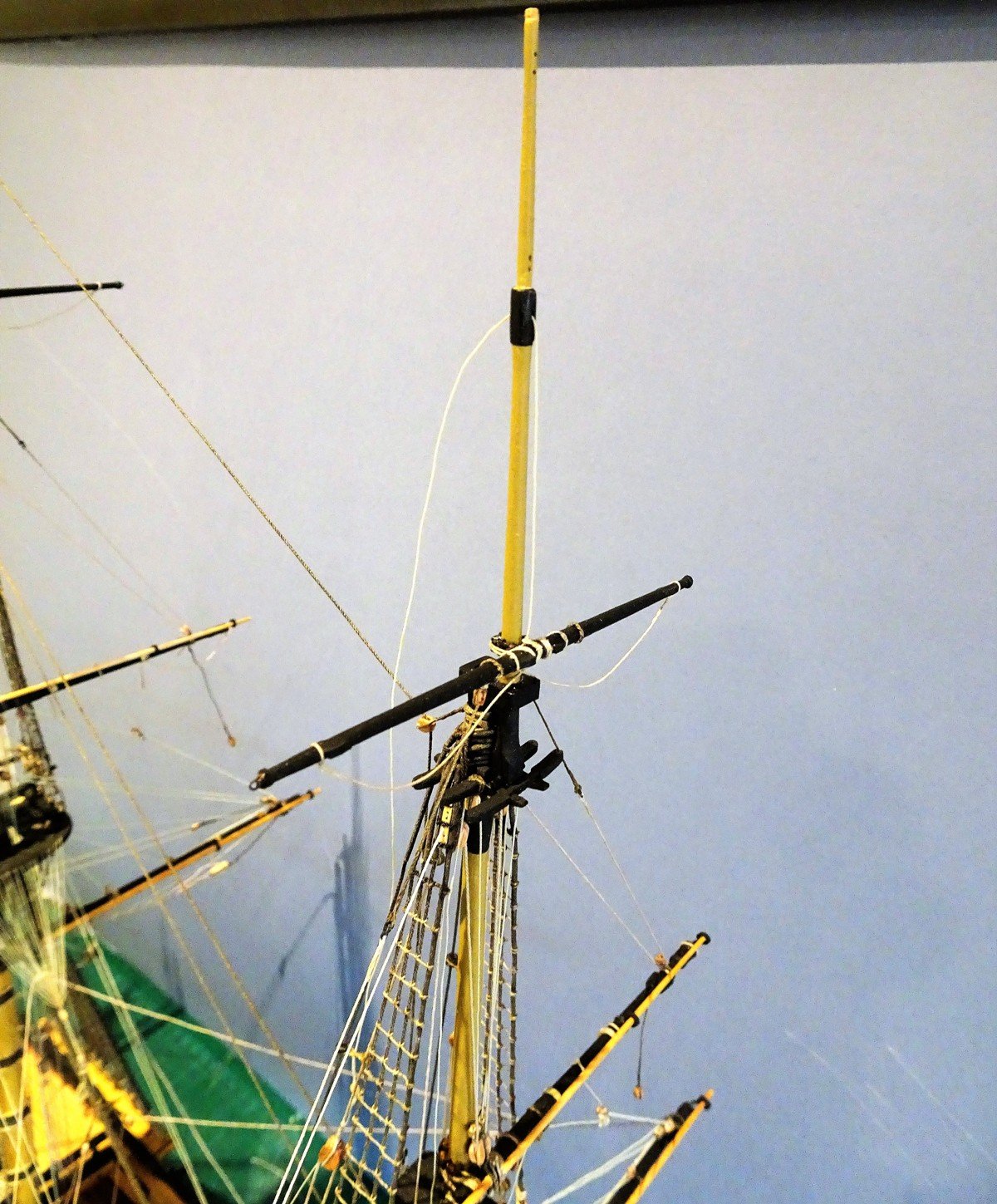
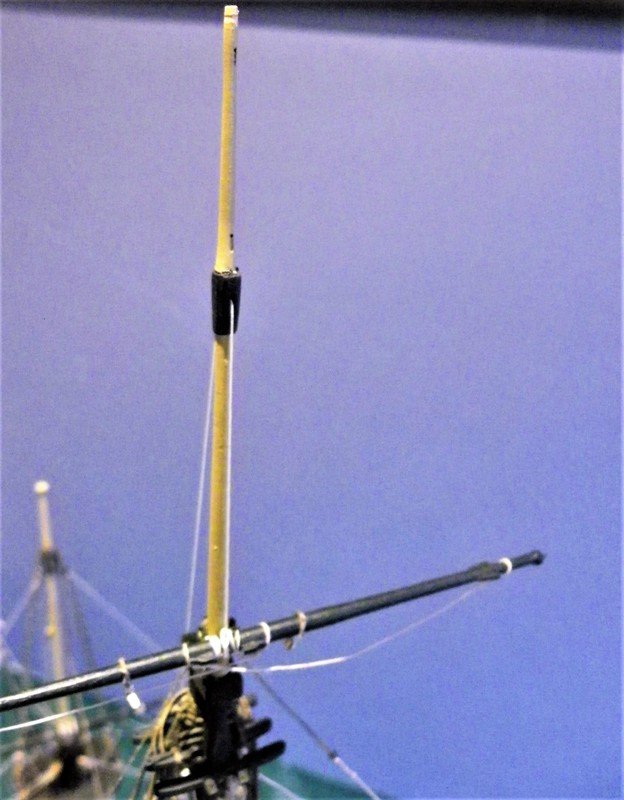
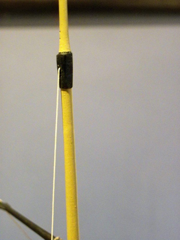
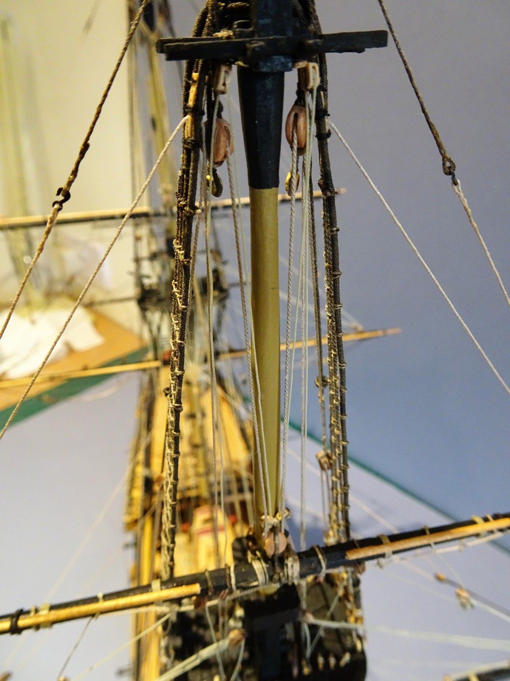
Trouble with Fore Topsail Yard Tye halyards Rigging can be a frustrating exercise particularly when available sources conflict with each other, and things just don't look right. The Running Rigging plan of the ffm indicates the fall to the Tye Halyard attaching to the channels on a long strop adjacent to the belfry, inside and just aft of the sixth deadeye. The kit plan shows a similar arrangement. When I trial this arrangement it becomes quickly apparent that there is a tendency to chafe against the Fore top, Topmast shrouds, and Lower shrouds I work on the principal that if it binds or chafes the lead must be wrong. I have moved the attachment ring as far back on the channel as possible, but even so the lines run very close to the top. Lees says - close abaft and inboard of the second topmast backstay. (Pegasus only has one Topmast Backstay but this attaches to the stool aft of the channel.) All the references I have looked at show the Halyard clear of the Fore top on contemporary models. Even with moving the channel position aft the halyards pass very close to the aft side of the top and the Topmast shroud. (The clip is to temporarily hold the Topsail yard down against the pull of the halyard.) Lead of the halyard down to the channel. One other fitting not mentioned in the ffm, but noted in Lees, is a bullseye stropped to the Tye thro' and around the Topmast backstay for the purpose of reducing twist in the tye block given the long length of the tackle. This also has the effect of holding the halyard a little away from the Fore top, which assists in modelling terms at least. There are photo's (plates 32 and 39) in Lees book of a 20 gun ship model showing this feature. This is a shot taken at the same angle as that in Lees book. Lees says: During all periods the block in the end of the tye was connected by a strop to a loose bullseye on the Topmast backstay.(usually the second backstay from forward.) The lower blocks of the halyard to the tye were always seized or hooked close abaft and inboard of the second topmast backstay, or the stay carrying the bullseye. When the stay came to a stool the halyard block came to an eyebolt in the ships side, and when the stay came to the fore channels the halyard block was secured to an eyebolt in the channel. This raises more inconsistencies as on Pegasus the backstay is on a stool but the halyard is on the channel according to ffm and the kit plans. There is little room in that area on Pegasus to attach an eyebolt to the ships side abaft of the stay to take the halyard strop, although an eyebolt in the stool abaft the stay might work, but is not evidenced in any model I have seen. The method as I have rigged it works, but there is always a nagging doubt...... Steel says: The tie-blocks are then spliced in their lower ends, and connected by their haliards to a single-block, that is strapt with a long strap, with a hook and thimble, that hooks to a swivel-eye-bolt in the channel on each side: the leading-part comes in through a block lashed on each side; the foremost ones abaft the forecastle, and the after ones on the quarter-deck. Fore and Main Topsail Yard lifts. There are some variations in the arrangements of the Topsail yard lifts, but this is what Steel has to say. LIFT-BLOCKS are strapt with an eye to the size of the yard-arm. The lift reeves through the lower sheave in the sister-block in the topmast-shrouds, and through the block on the yard-arm. The standing-part hooks to a becket round the topmast-cap, and the leading-part leads down the side of the mast, and belays to the dead-eyes in the lower shrouds. This is the arrangement I have followed. For the half hitched span around the topmast cap I have used 30mm 'tarred' line (133mm long) with a becket in each end. The running end of the lift is fitted with a hook to attach to the span. The kit instructions show a toggle fitted into the end of the running lift line which fits thro' the span eye to secure. This is a valid alternative to a hook, but as I had some of Chuck's little 3mm black plastic hooks which are perfect for the job I went with them (the brass hooks are slightly bigger) Having hooked into the span the lift runs down thro' the yard block, back up thro' the lower sheave of the sister block, and down thro' the top to belay at the lower shrouds. I have opted for shroud cleats which are much easier to belay to than tying off at the rail. The downside is that attaching shrouds cleats is also a fiddly business. Fitting the lifts also involves fitting the Fore and Main T'Gallant masts, as with the other topmasts no glue is involved but for the moment there is plenty of rigging work lower down. I next attend to the Mizen Topsail Lifts. There are eyes (or in my case False eyes) spliced around the yard arm) taken up thro' the lower sheave of the sister blocks and down to belay at the rail. B.E.


- 366 replies
-
- 1
-
-
- pegasus
- victory models
- (and 2 more)
-
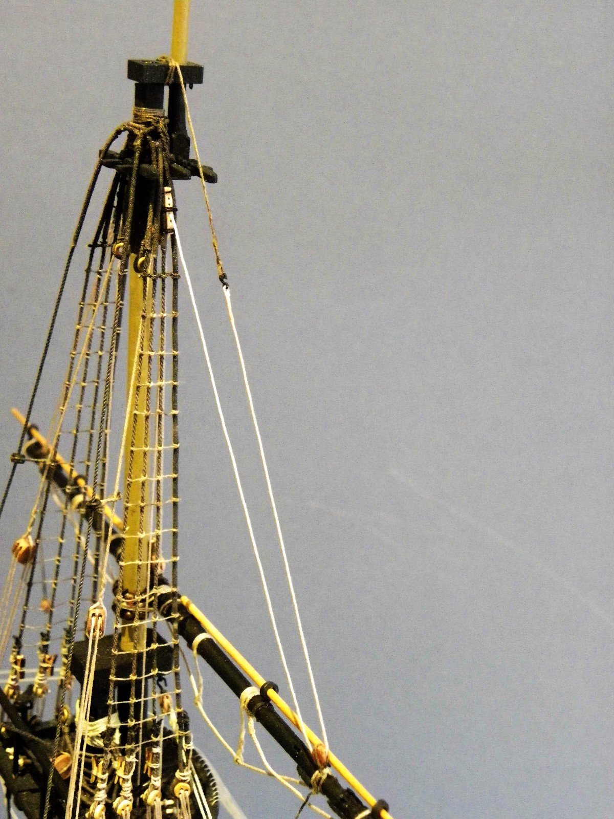
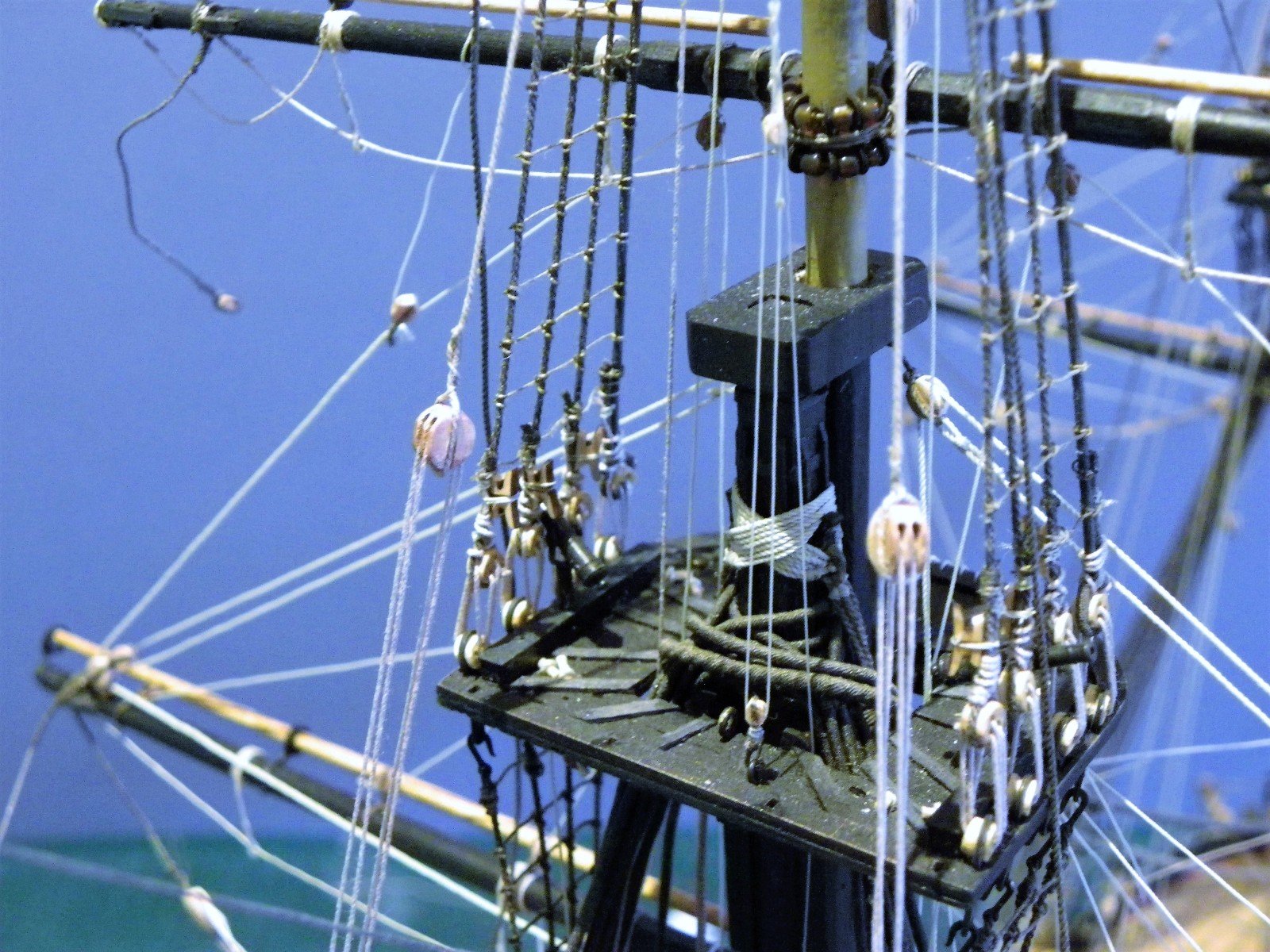
Topmast Tyes. For those following TFFM there is a confusion. ffm para 19.15 indicates a 14" single block for the yard tye. (as I had fitted) 19.24 second para indicates the tye passing thro' the aft sheave of the double tye block on the yard?? Re-checking, Steel indicates a single 14" yard block; I think David Antscherl has used the block requirements indicated in Steel, but followed the rigging arrangement given in Lees (p83) which calls for a double yard block and tyes suspended from the mast head. This is a damned nuisance and presents me with a problem given that the yards are now fitted, together with served strops and secured parrels, both tricky time consuming operations. However, This is what Steel has to say. TYE-BLOCKS lash at the topmast-head close up to the rigging, under the collar of the stay, as the lower ones; and the blocks on the yards lash under the fore part of the yard, as the lower ones, and reeve with a double tye, in large ships, and a single tye, like the lower, in small ones. The standing-parts of the double-tyes clinch round the mast-head, then reeve through the double-block upon the yard, and up again, and reeve through the block on each side the mast-head. The tie-blocks are then spliced in their lower ends, and connected by their haliards to a single-block, that is strapt with a long strap, with a hook and thimble, that hooks to a swivel-eye-bolt in the channel on each side: the leading-part comes in through a block lashed on each side; the foremost ones abaft the forecastle, and the after ones on the quarter-deck As Steel has indicated single blocks in his tables I accept that he considers a sixth rate sloop is a small ship and with the narrative qualification above, for me it is sufficient reason to leave matters alone. Furthermore his tables specifically show use of a double block for vessels of 20 guns upwards, whilst this requirement is lined out in the table column for those of 18 - 14 guns. Make of it what you will, but I am content to leave things alone. Tyes - 4½" line / 14" thin double blocks. I am using Syren 0.45mm line and 5mm blocks. The first block is false spliced into one end,(which is easy to do) the line is passed thro' the block suspended below the trestletrees on one side, down thro' the yard block, back up thro' the upper block beneath the trestletrees and the other block is spliced in. (not quite so easy) It helps to draw the first block up as far as it will go to allow maximum working line to splice in the second. When equalised the tye blocks should hang about level with the lower mast cap. For the lower single block (14" (5mm)) there is a long strop,(0.45mm line) hook and thimble arrangement attached to a ringbolt in the Channels. The hooks I made from eyebolts, and the thimbles from flattened brass eyelets. The overall length of the strops on my Pegasus worked out at 37mm including hook and block. Halyards These are of 0.30mm scale line attached to the lower single block to make up the tackle with the Tye block, with the fall belayed to the rail. The strop extends the block above the rail The Starboard side strop hooked to the channels, it is secured around a thimble and false spliced. I won't tie off the halyards for some time yet as they tend to block out access to the Quarterdeck. B.E.


- 366 replies
-
- 2
-
-
- pegasus
- victory models
- (and 2 more)
-
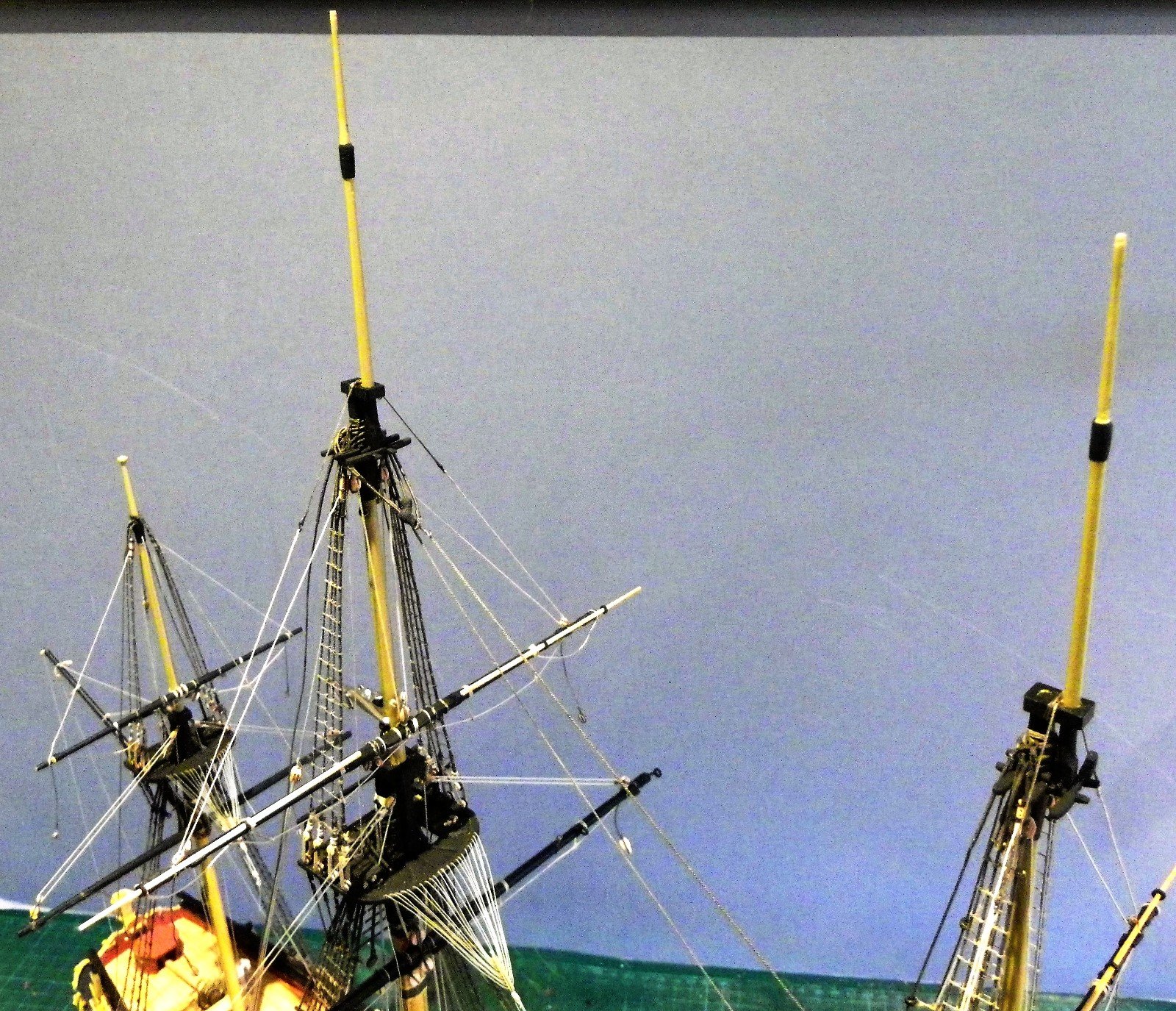
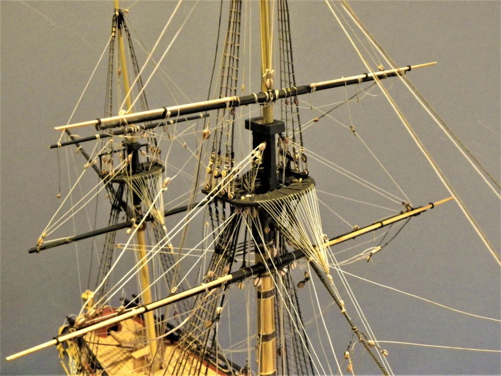
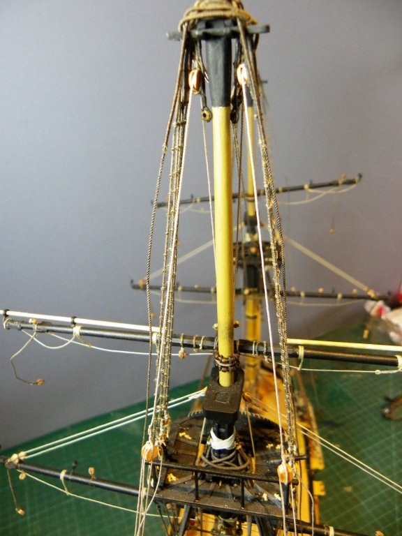
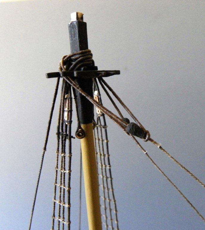
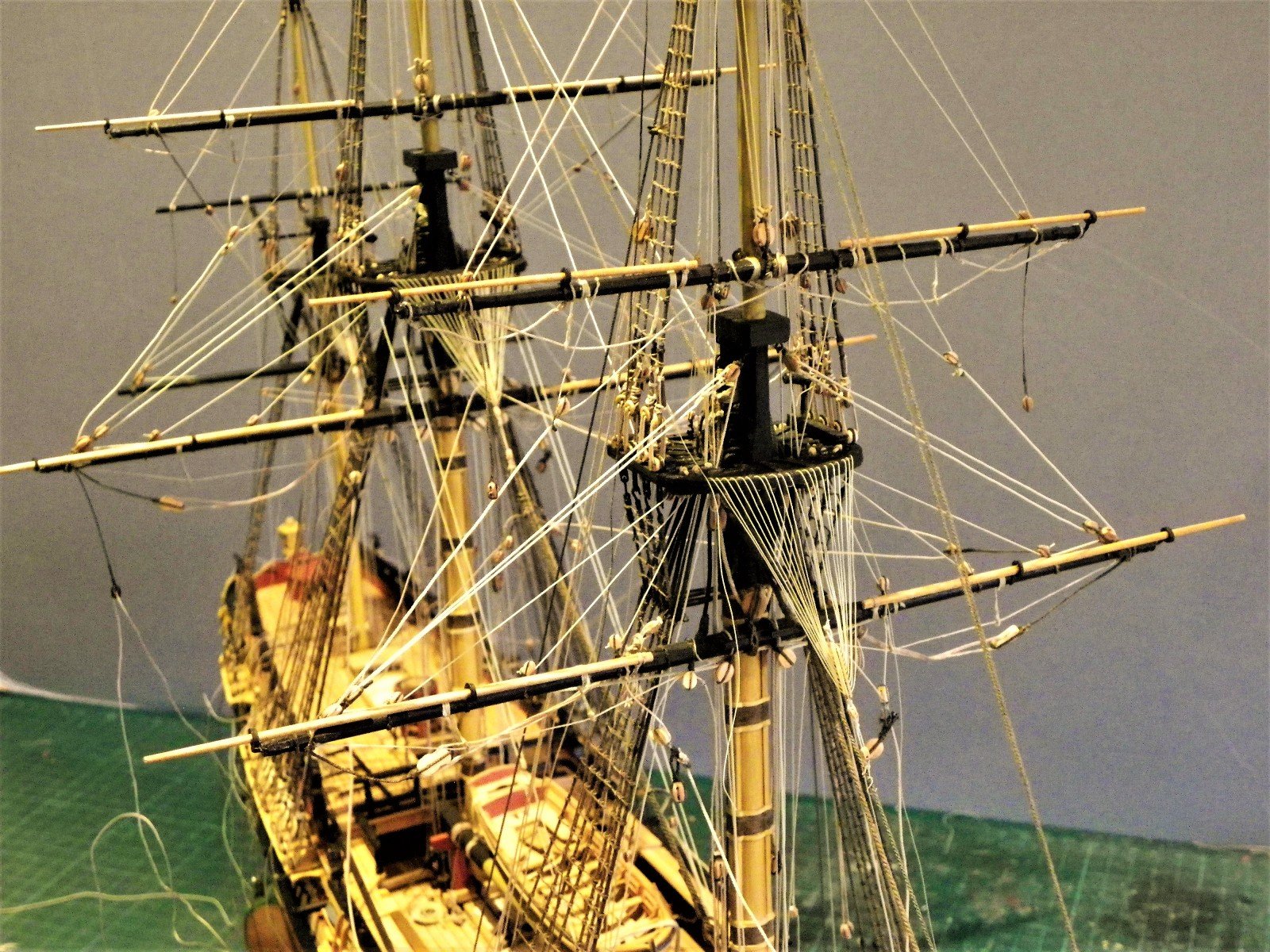
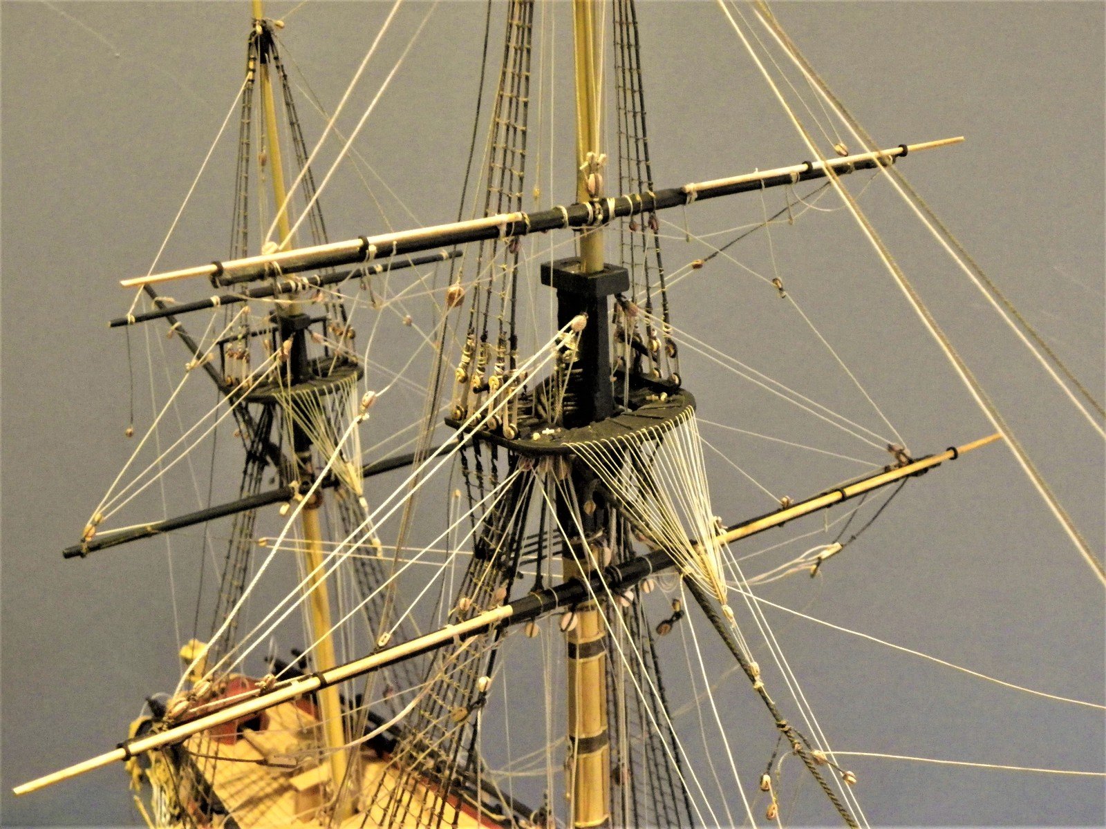
Mizen Topsail Yard I am rigging the yards in the lowered position and the ffm (p117) advocates pinning the Mizen Topsail Yard to the mast to provide some resistance to the pull of the lifts, there being no counter available from the braces which in this case are insufficiently angled to do the job. This is good advice which I have taken. As my Pegasus has a pole head Mizen I have also adopted the use of a Truss parrel to secure the yard to the mast, rather than the Ribs and truck arrangement which would in any case be pretty small on the Mizen Topsail Yard. It is convenient at this point to complete the Mizen Tye and Halyard, not least because a tackle has to be rigged on the Mizen top. The tye is eye spliced around the yard and is taken thro' the sheave below the hounds of the Mizen topmast. I used Syren 0.45mm line. (2) 3mm single blocks are required; one spliced into the tye and the other hooked to the starboard Trestletree inside of the Top rail. With the yard in the lowered position care has to be taken to position the upper tye block correctly, to allow sufficient hauling distance in the tackle to raise the yard. The fall is attached to the strop of the Upper block before making up the tackle and then passing thro' the top to belay around a mast cleat on the Mizen Mast. It will quickly become apparent why it is not a good idea to fix the Top rail too soon on the Mizen, or for that matter the other mast tops either. The horses take a bit of disturbance during the yard fitting and will require a little adjustment once the process is completed. This completes the attachment of the Topsail Yards to the masts. I will now move onto the Topsail Lifts, and tyes for the Fore and Main Topmast yards which are currently held by temporary lines. A good time also to review what other elements of the running rigging would best be fitted at this stage. B.E.


- 366 replies
-
- 2
-
-
- pegasus
- victory models
- (and 2 more)
-
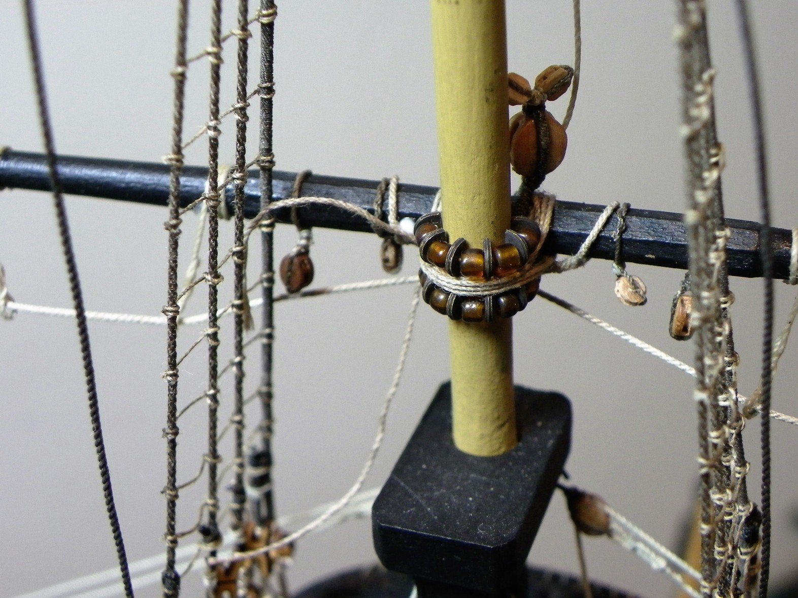
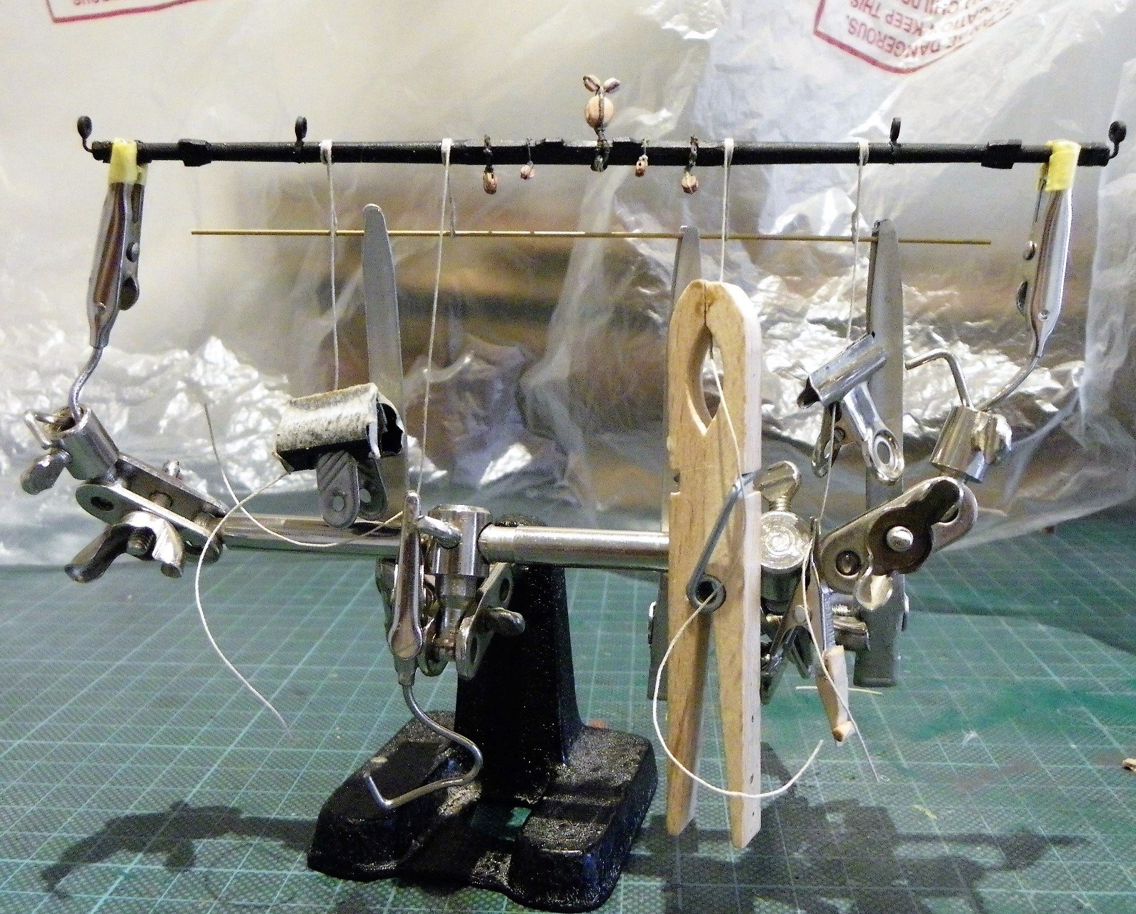
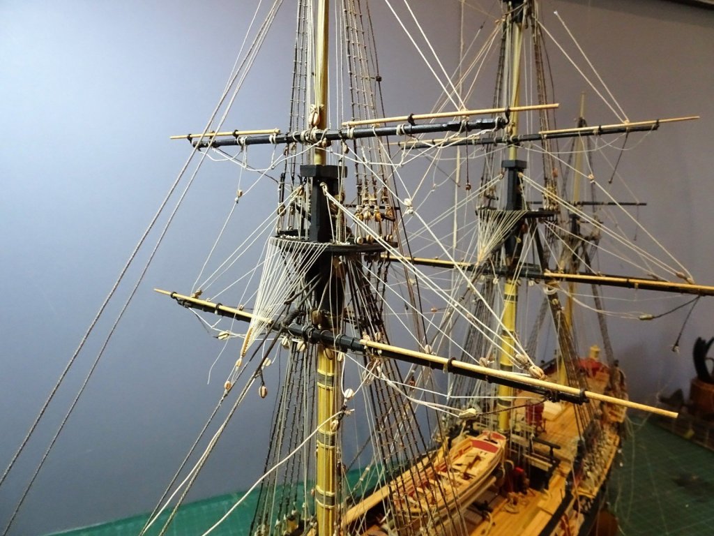
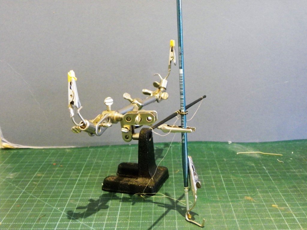
Main Topmast Yard. Requirements. For those who may be interested this is my sequence of attaching fittings to the Topsail Yards. 1) Tye, sheet, and Clue blocks 2) Yard boom irons (inner) 3) Stirrups 4) Horses 5) Brace Pendants 6) Lift Blocks 7) Flemish Horses. 8) Boom Irons (yard arm) Same old same old with the Main Topmast Yard, once the blocks are attached the stirrups are fitted and stiffened. There's a fair bit of needle work involved in yard rigging. The Parrel line is fitted over the yard and the Ribs and trucks slipped on. A temporary tye is used to support the yard whilst the parrel lines are taken around the mast. A clip is used to prevent the beads running off the end of the lines during the process. Working on the parrels is a tricky business, constantly have to be aware of the head visor bashing against the mast and yards as I peer in to get focus. Once the lines are around the mast and yard things get a little easier. Onto the Mizen Topsail yard which thankfully has fewer attachments. B.E.


- 366 replies
-
- 1
-
-
- pegasus
- victory models
- (and 2 more)
-
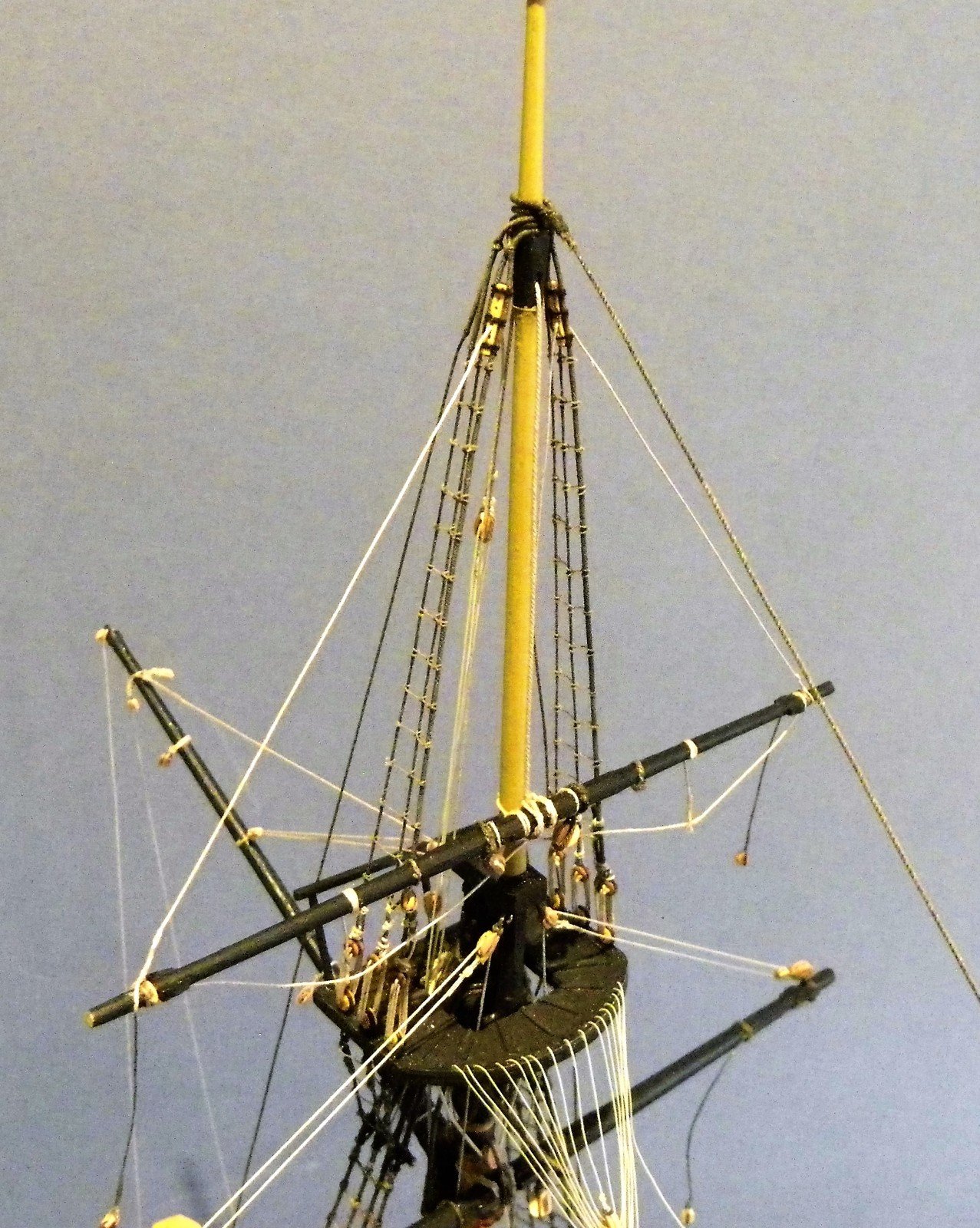
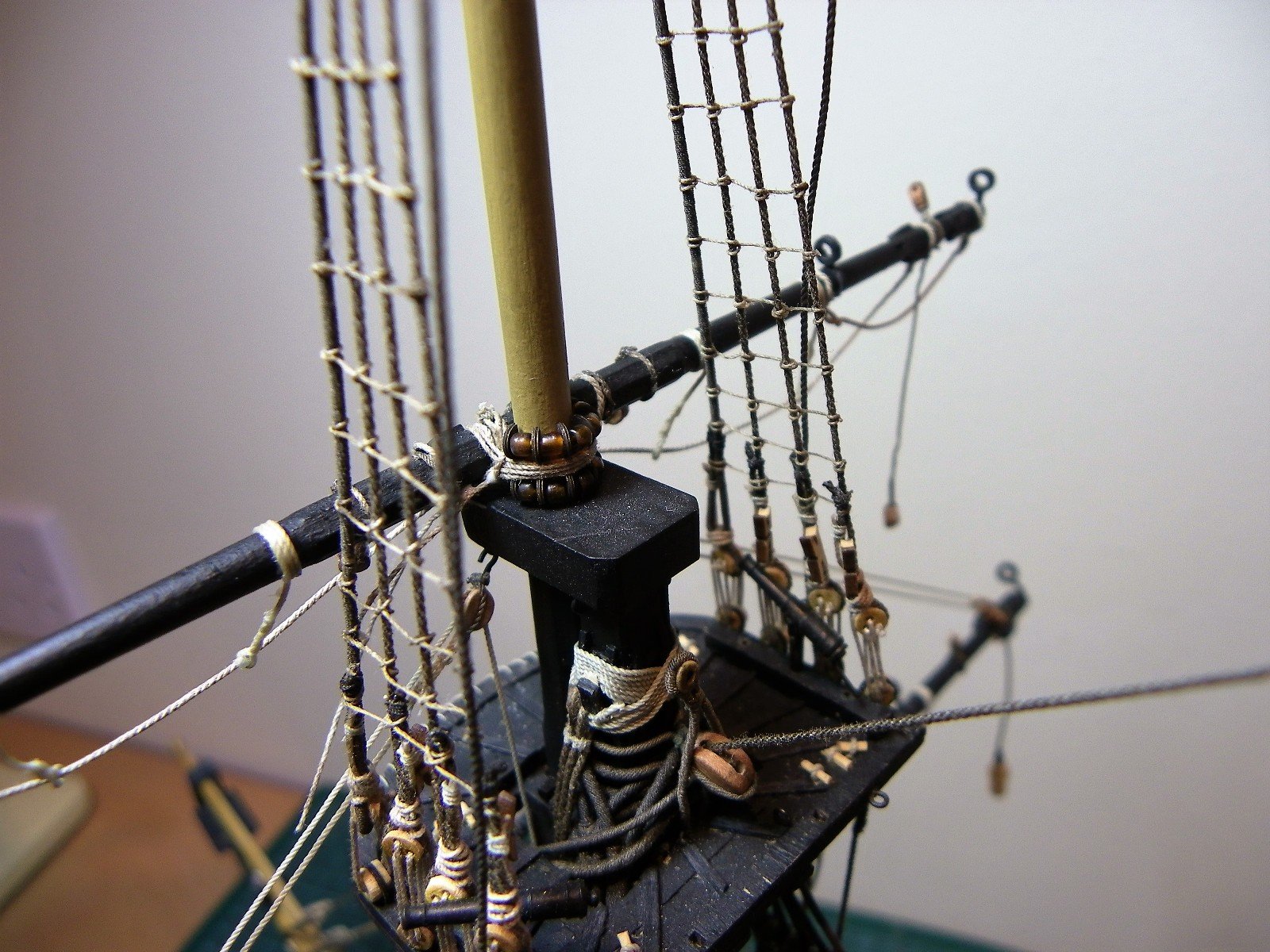
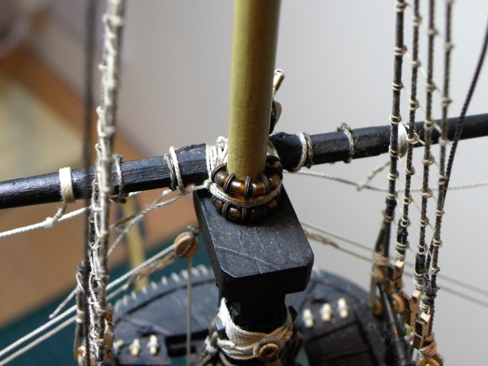
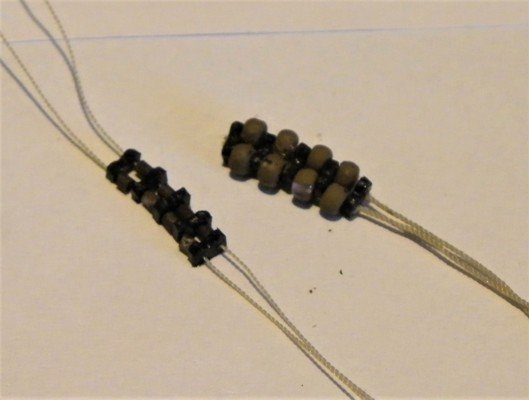
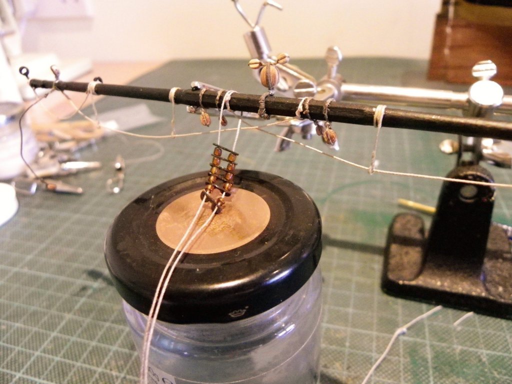
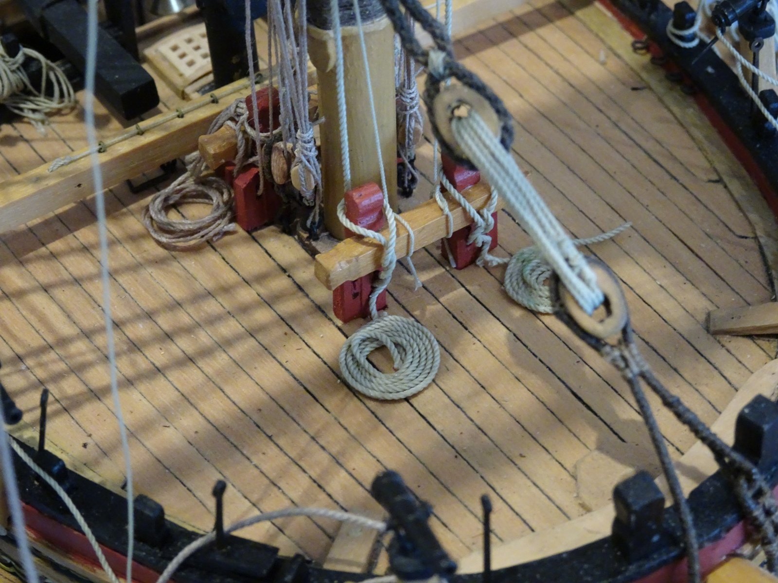
Parrels The kit supplies brass etched parrel ribs but at near 8.5mm long are over-scale. The correct scale size is around 5.5mm long, with a Max Width of 1.6mm, and a thickness of 0.4mm. There are six ribs / five trucks in two rows. Trucks - 1.6mm Ø and 2.28mm long. 0.25mm scale line (115mm long) x2. I found some smaller brass etched ribs, the origin of which I forget but they were ok for size and I had enough for both Fore and Main Topsail Yards. Without them I would have made some from boxwood strip. The one end of the parrel lines were secured to the yard before it was fitted to the mast, along with the ribs and trucks. and a temporary tye line was fitted to hang the yard from the topmast head whilst the fiddly business of attachment was completed. For the trucks I had some slightly elongated seed beads which fit the bill. For the line I used Syren 0.3mmØ stuff. Don't make the line too tight or it will be difficult to get the tye block on the yard to sit centrally due to the thickness of the served strop. I will now move onto rigging the Main and Mizen Topsail yards. B.E.


- 366 replies
-
- 1
-
-
- pegasus
- victory models
- (and 2 more)
-
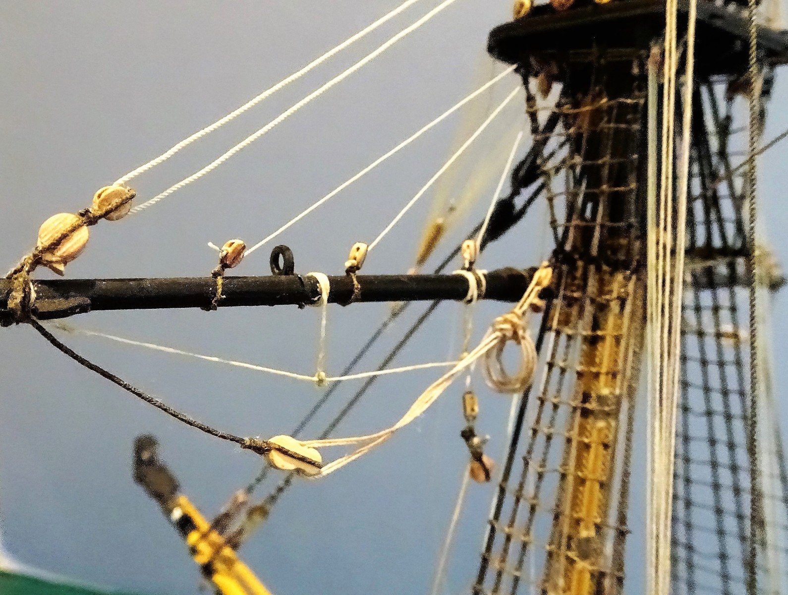
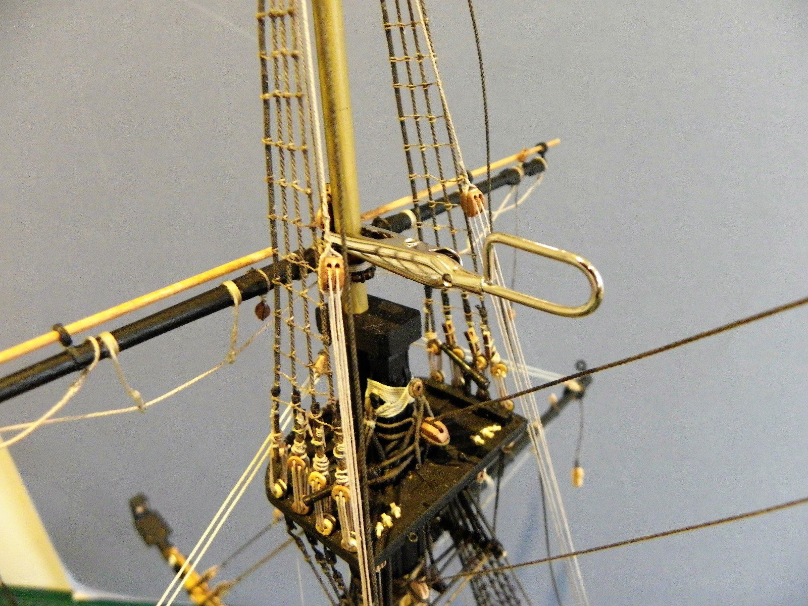
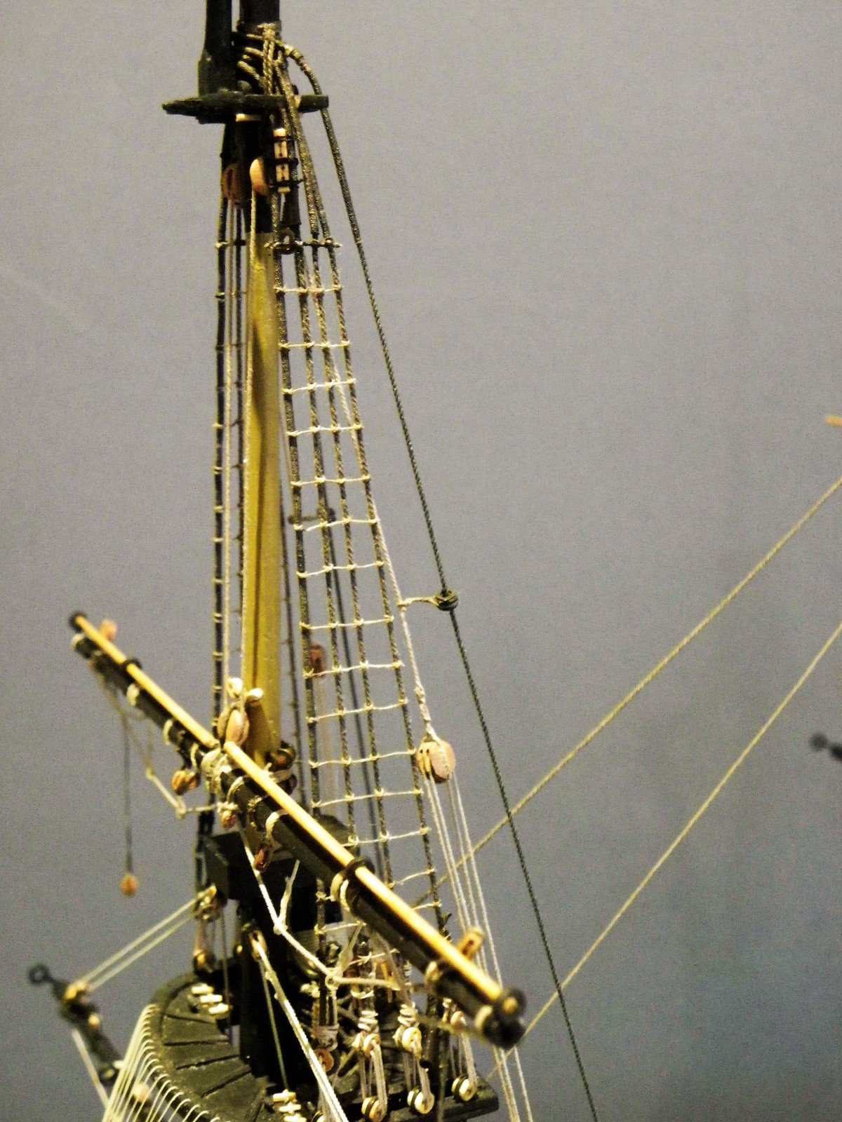
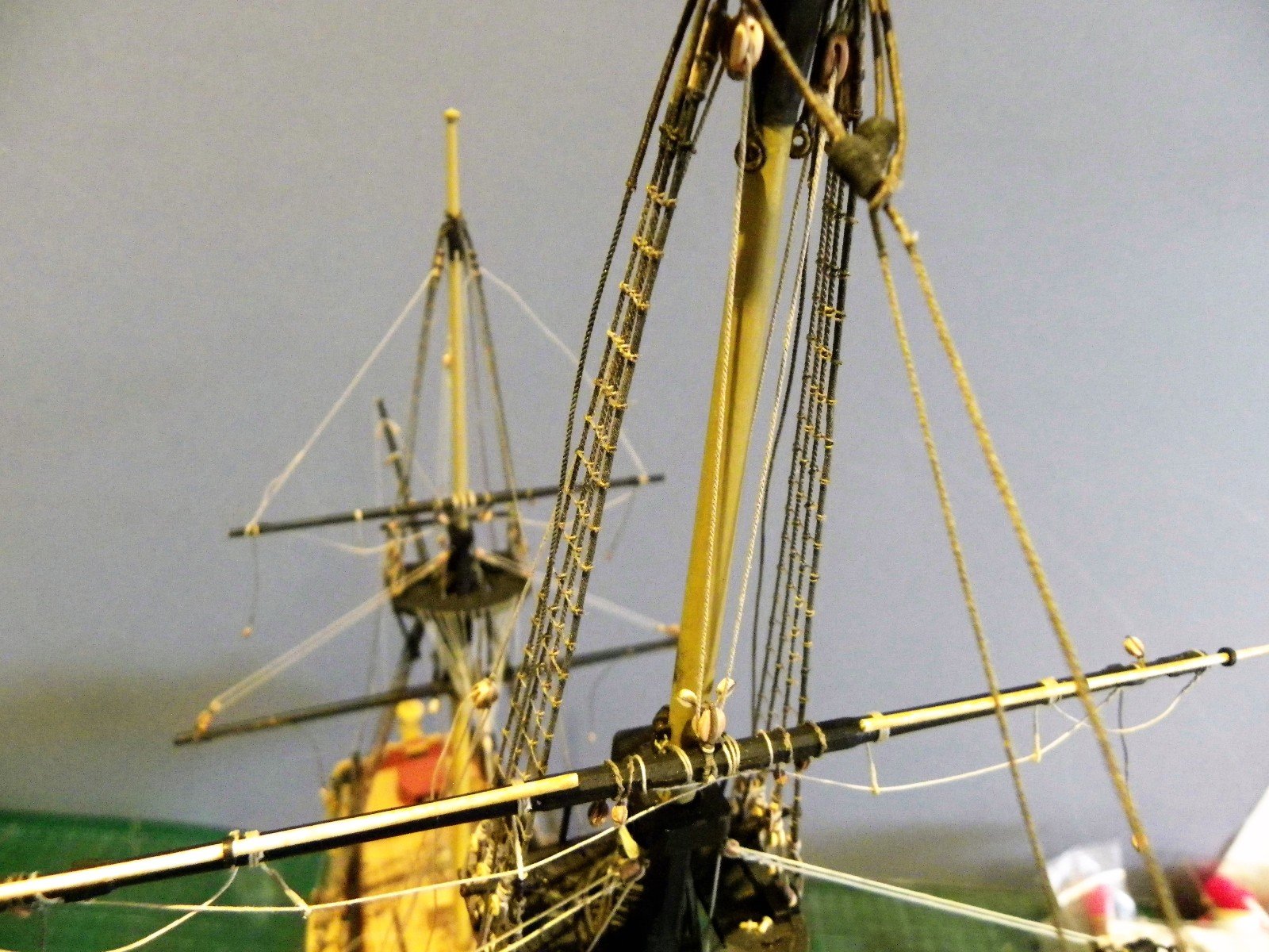
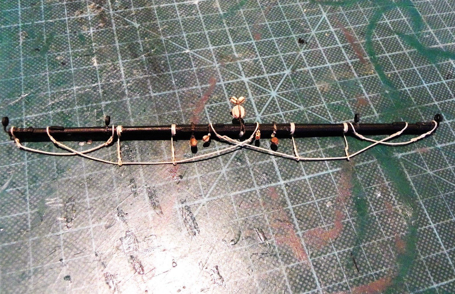
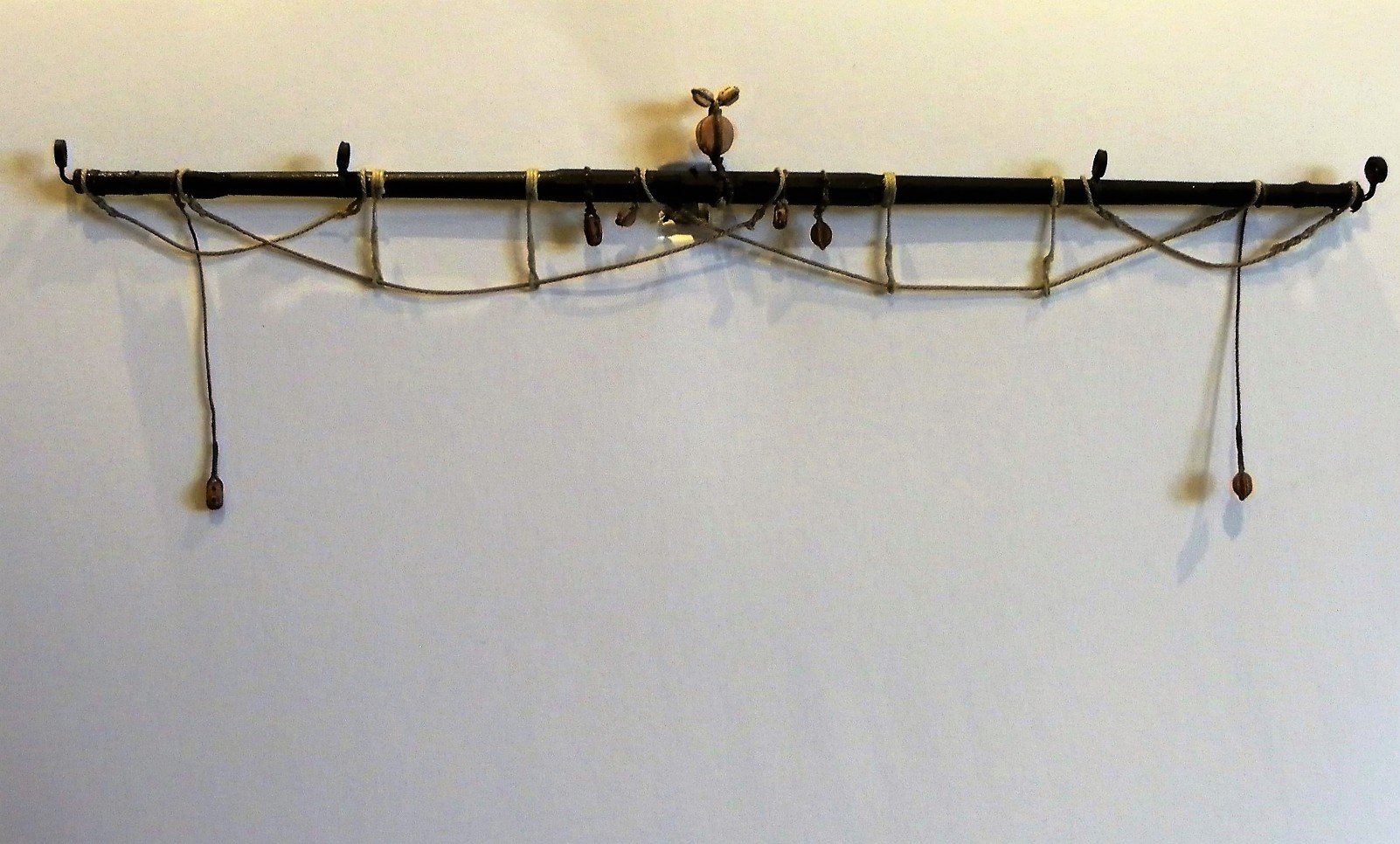
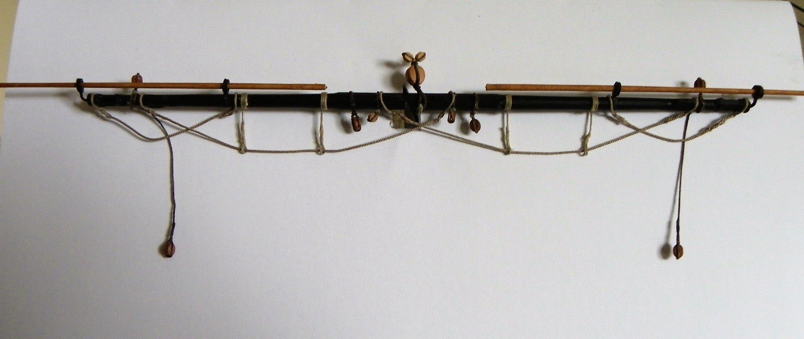
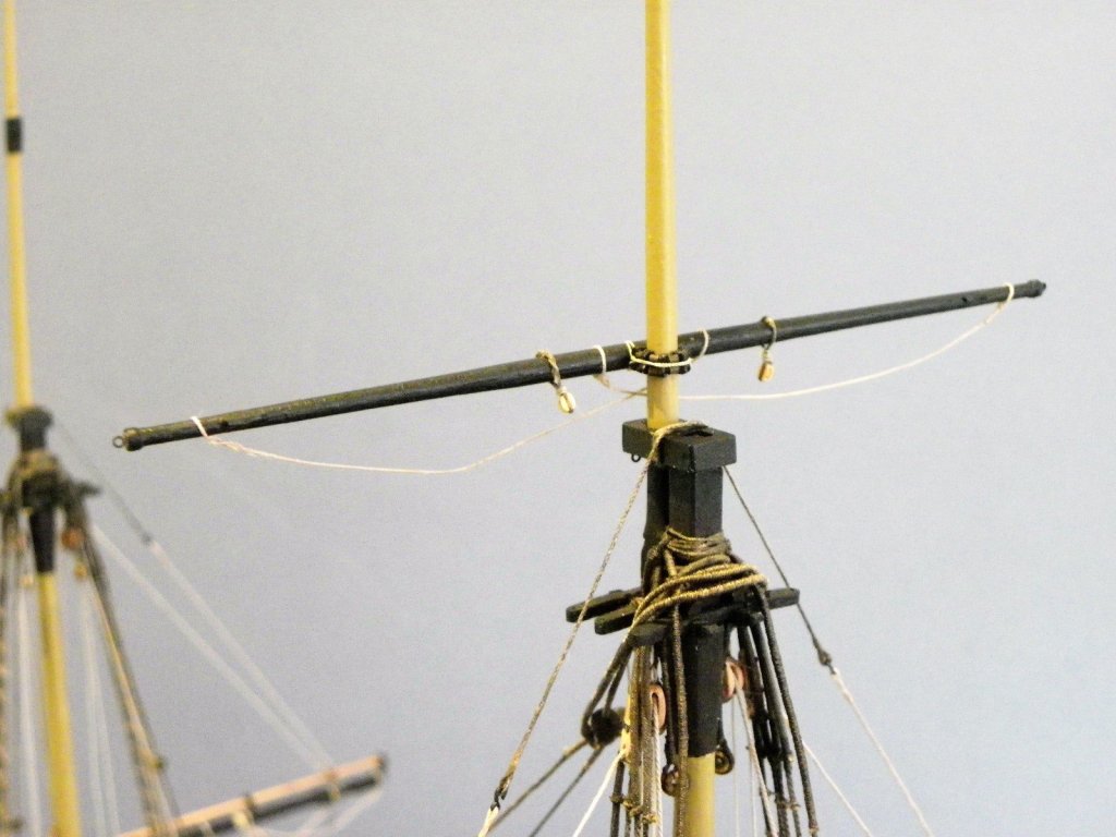
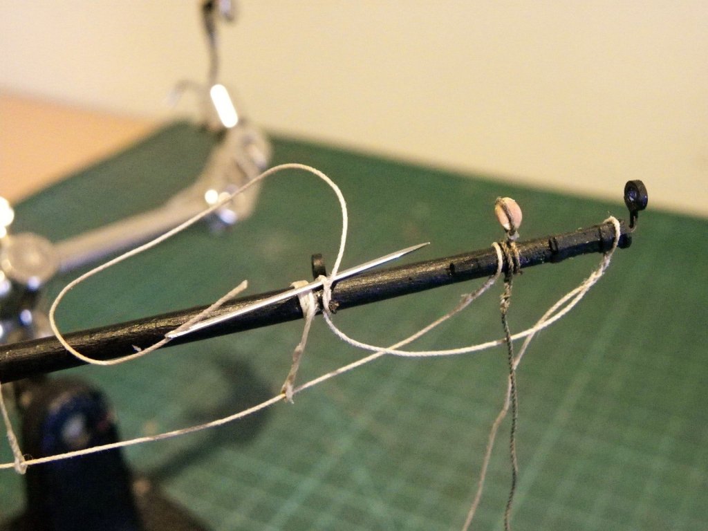
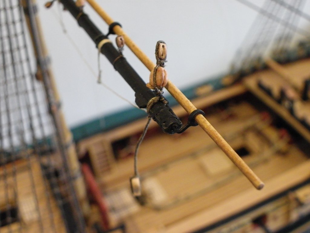
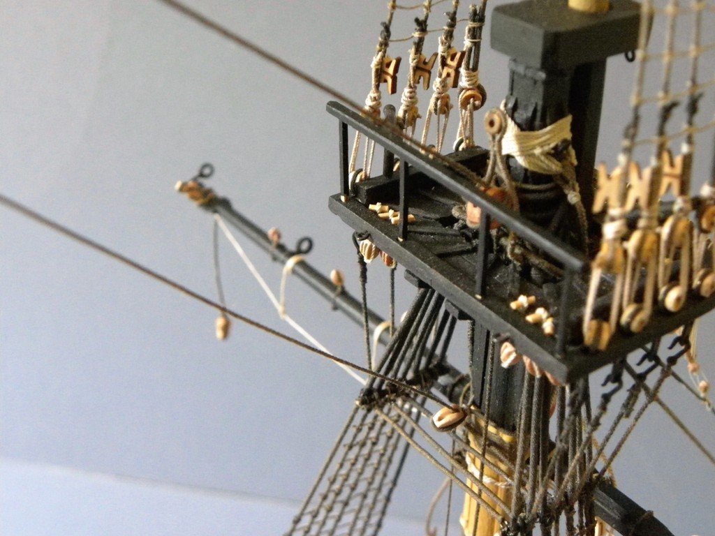
Topmast Yards Up to this point I have not attended to the Fore Topmast rigging, for which I will need to attach the Jib, a task I am leaving as late as possible. Without the encumbrance of the Topmast stays it will be easier to fit the Topmast yards, so this will be the next step. Fore Topmast Yard. Requirements. (1) 14" Tye Block (5.5mm) 4" strop.(0.50mm)0.45mm Syren served with 0.1mm Morope (2) 7" Buntline blocks (2.77mm) (2) 6" Sheet Blocks (2.38mm) (6) 8" blocks Clue, Lift.(2½")strop (0.30mm syren line) and Brace Blocks (3.17mm) 2" line for Stirrups (0.25mm) 3" line for Horses / Flemish Horse( 0.37mm) Studding Boom irons. 18.0' long (85.7mm) 3" line (0.4mm) 14" parrel ribs (5.55mm) The yards are made but no fittings attached, a time consuming exercise ahead. Topsail Tye Block with attached Buntline blocks is first on the yard. Drilling the yard for the Boom irons. Boom fitting My method of rigging the yard footropes and stirrups I more fully covered earlier in the build. Fitting the Stirrups, They were stiffened using pva. A brass bar is used to maintain the stirrup length across the yard. Horses and Flemish Horses fitted. Brace Pendants. According to Steel the pendants are 3 fathoms each in length = 18' and the tffm repeats this measurement in the narrative. (p123) but... this seems a very long length for a brace pendant, and the drawing on p122 at 1:48 scale = 45mm.equal to a (7') pendant. The tffm rigging plan sheet at 1:96 also scales to an equivalent (7'6") Lees says 0.3 of yard length = to 49.5mm (10' 3") for Pegasus @1:64. This drawing from Steel's work shows pendants more to the scale I had envisaged, but it seems to go against his own narrative. The kit plans show Brace Pendants which are also are a direct fit to Lees 0.3 of yard length. Having faffed around I have finally settled on the 0.3 ratio which also suits my eye. The final pair of blocks over the yard arm are the lift blocks which are eye spliced and butt against the brace pendants. This completes the fitting out of the yard attachments. In my next post I will deal with the parrel, and yard attachment.


- 366 replies
-
- 1
-
-
- pegasus
- victory models
- (and 2 more)
-
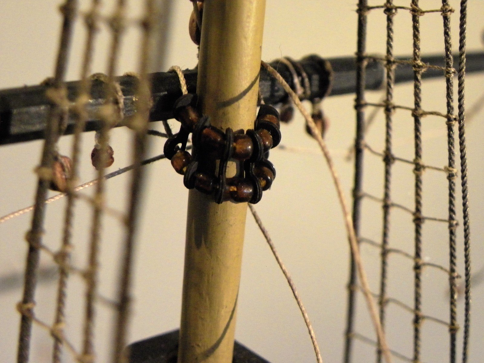
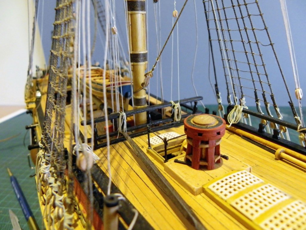
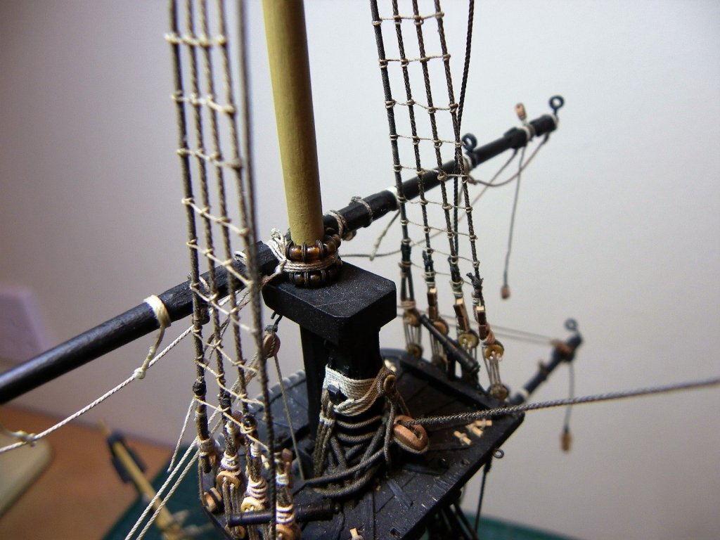
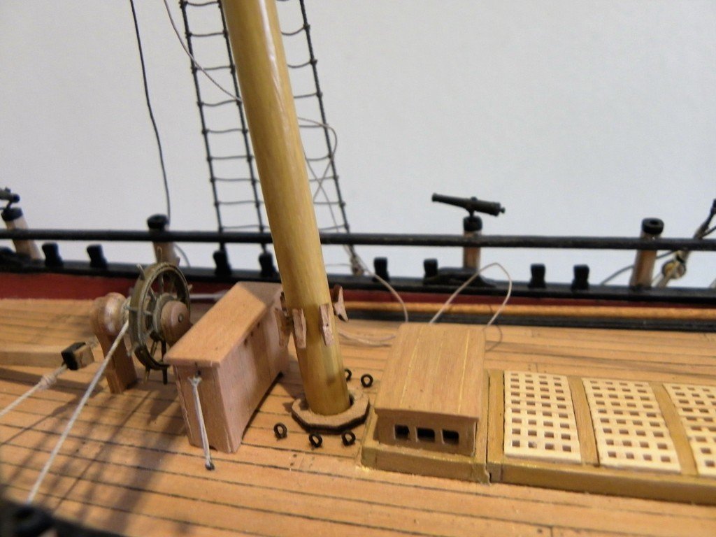
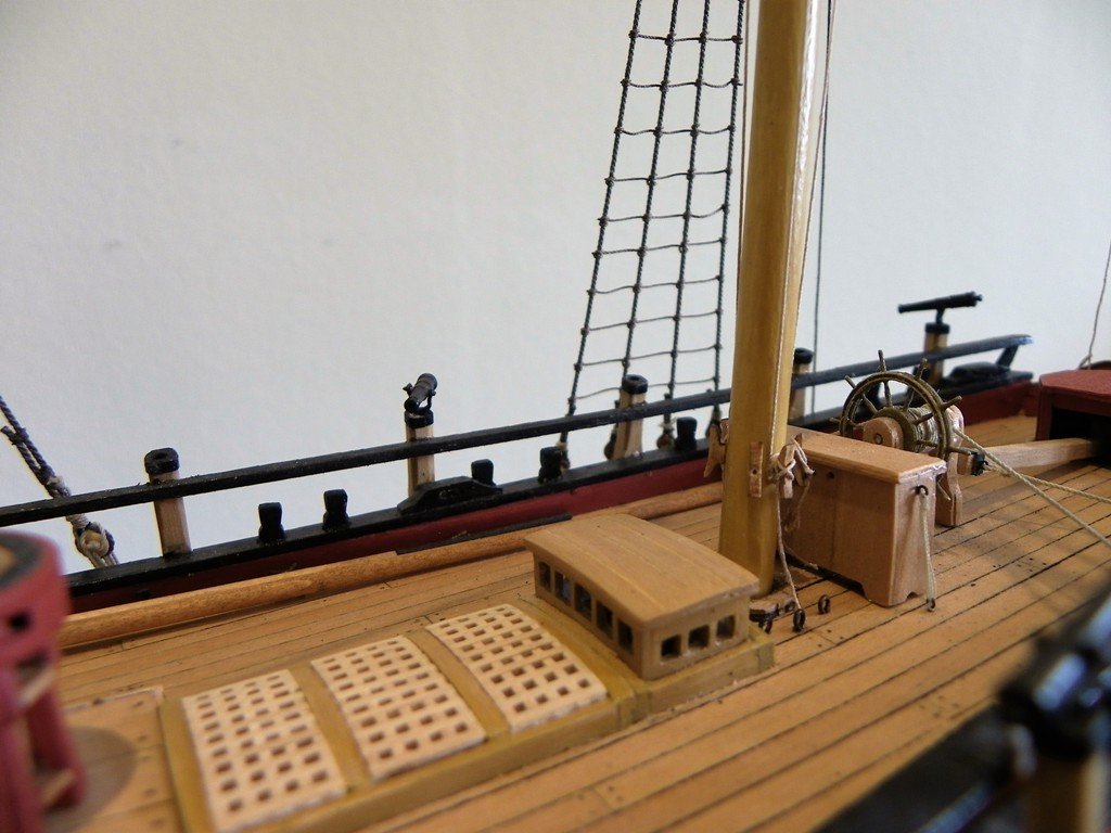
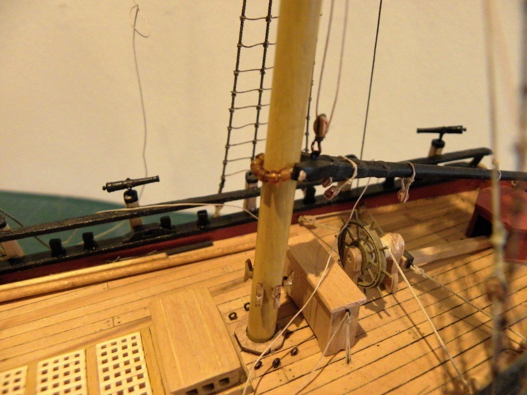
The Gaff Fitting Requirements. 3pr (6) 6" brail blocks (2.38mm)2.5mm (1) 6" peak halyard block, with hook(1) 6" double block at Mast Cap.(with hook) 2" strops (0.25mm) (1) 4" ensign block (1.58mm) 2mm (2) 5" Mizen topsail brace blocks (1.98mm)2mm (2) 7" throat halyard blocks (2.78mm) 3mm 2" strop / span/ halyard lines. Parrel beads 1mm As I reached this point I realised that I should have added cleats around the Mizen mast, a task much easier done before I stepped the mast and added the Mizen standing rigging. There are six cleats around the Mizen mast, and it was a little tricky to get them evenly spaced and level with the mast in place. I used Syren 5mm cleats for the job which I drilled to take wire pins to secure them the mast. The Gaff fitted, the parrels are some conveniently sized elongated beads. The throat halyard block is hooked to the top of the Gaff. The Gaff is raised. The Throat halyard tackle can be seen in this shot. The upper block is long stropped around the Mizen Trestletrees, and a 0.20mm halyard line is seized in. The Peak Halyard in place, it was necessary to tweak the top rails to allow a clean run for the tackle. A total of 13 blocks are required to rig the Gaff. The Brail blocks are quite tiny (I used 2mm+ blocks) and are required to be stropped close together either end of a very short line to then be seized around the gaff. Temporary Vangs have been fitted to assist the rigging of the Gaff. B.E.

- 366 replies
-
- 1
-
-
- pegasus
- victory models
- (and 2 more)
-
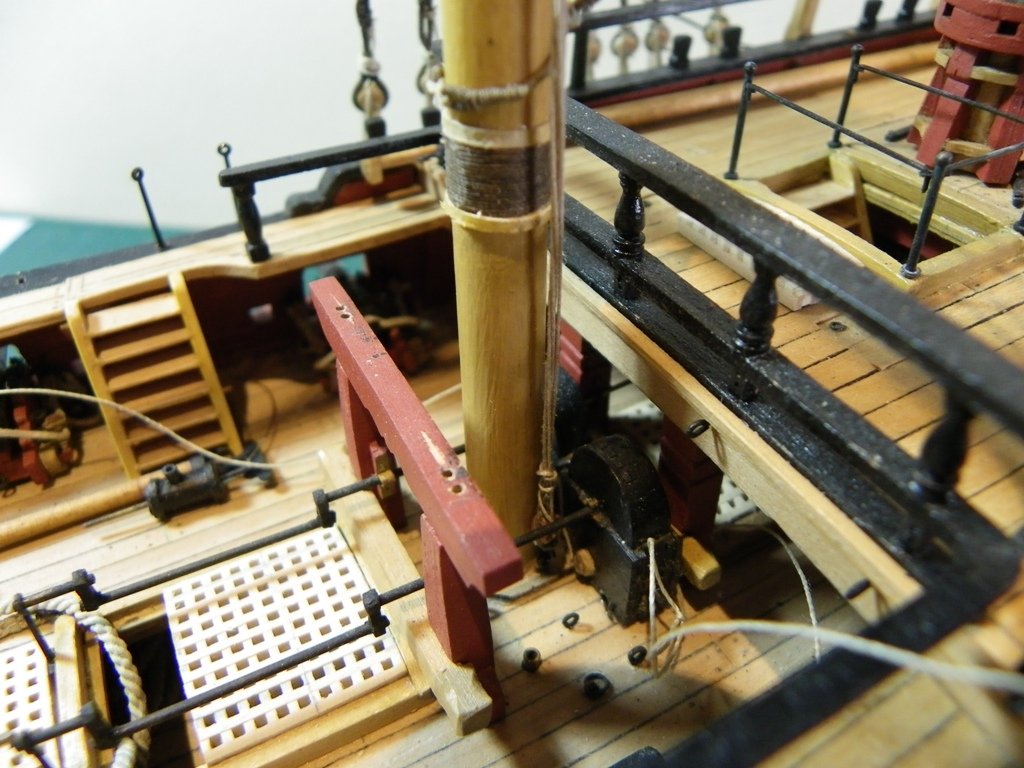
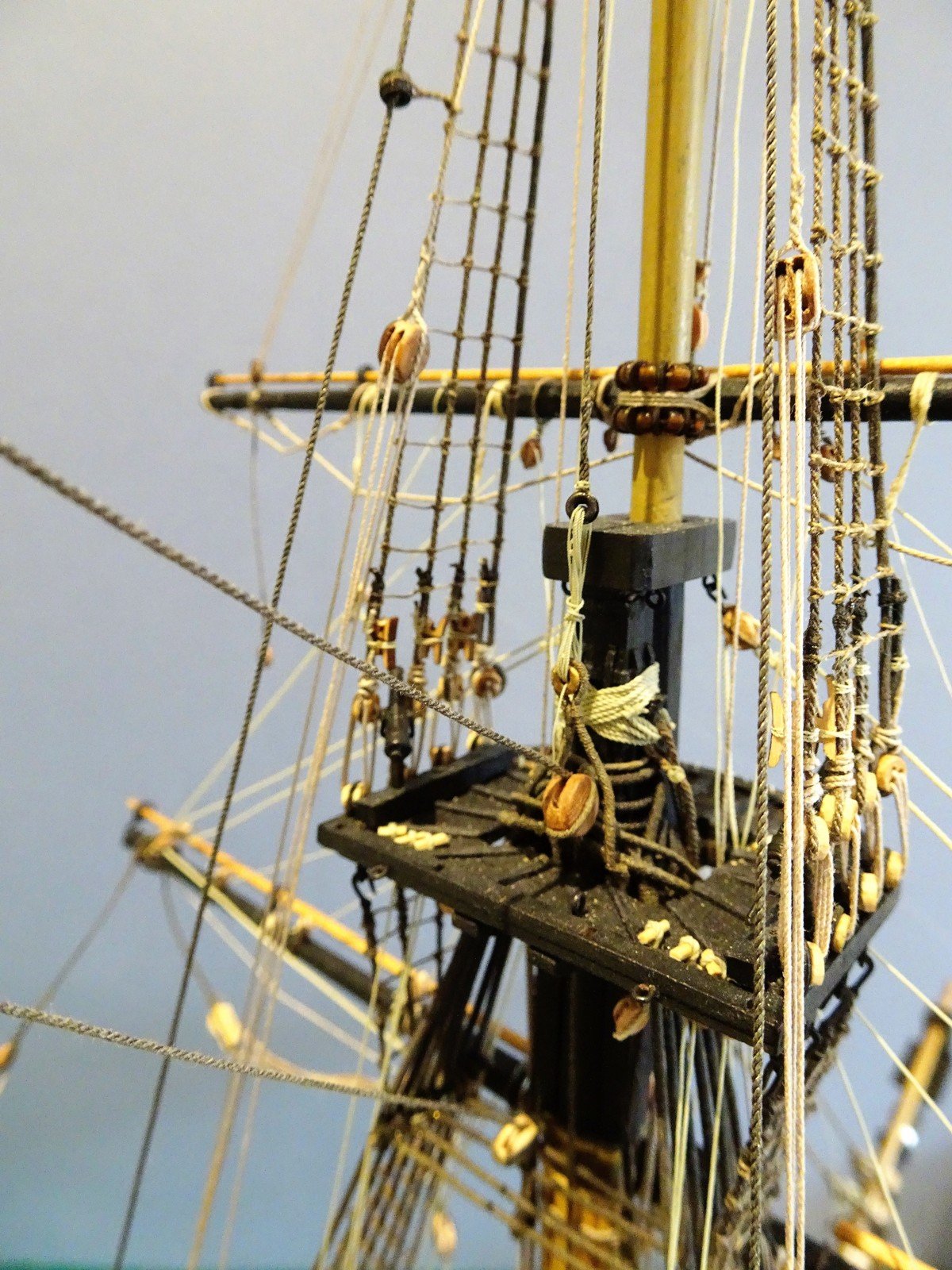
The Crossjack Yard Truss 3" truss (0.4mm) 7" blocks, (2.77mm) 2" falls(0.25mm) This is a single truss with a thimble to the port side of slings, the pendant seized to s/bd side, and the tackle belayed in the Port side Mizen channels. Pendant falls belayed in the Mizen chains. The slings I have gone with a simple arrangement seized around the mast top above the shrouds. Morope 0.4mm line was used for the purpose. The Crowsfeet have been disarranged slightly during the process but I have purposely not tied them off as yet to allow for re-adjustment. Before I move onto the Topsail yards I think I will attend to the leech and buntlines to the lower yards as these too belay at the base of the Fore and Main masts. Slings. 3" line 24' long Checking around for other attachments. Lower Yard lift blocks Fore and Main - 9"(3.6mm) 3" strops, 3" fall 0.4mm (180') 33.75" Lower Yard lift blocks Mizen 6"(2.38mm) 1½" strop. 1½"falls(0.20mm) I used Morope 0.4mm line for the lift falls, which are belayed on the Fo'csle timber heads adjacent to the Foremast, and Quarter deck rail for the Main yard lifts. For the Mizen I used Syren 0.20mm line. Falls belayed to the rail adjacent to the mast. The upper blocks are hooked to eyebolts beneath the caps. I won't belay the lift falls at present, and I also need to work out how to best form the coils of excess line, there are no convenient belay pins on Pegasus to assist the process. Topsail Yard Tye blocks 14" (5.5mm) 4" strop(0.50) These are conveniently attached at this point before the Topmast caps are fitted. They are suspended from the Fore and Main Topmast heads above the standing rigging in a long strop sufficient to hang just below the trestletrees. I trialled the strop length and calculated that it was 49mm in length, Syren 0.45mm line was used for the purpose. I sealed the line with pva 2mm short of each end, unravelled the very ends and joined them by finger rolling using pva. The join was then painted with more pva and left to dry. This method works very well with Syren line. The strops are dyed and secured around the 5mm Pear wood blocks. The strop join is placed at the bottom of the block where a spot of pva further reinforces the strength. Tye blocks fitted to the Main Topmast head B.E.

- 366 replies
-
- 1
-
-
- pegasus
- victory models
- (and 2 more)
-
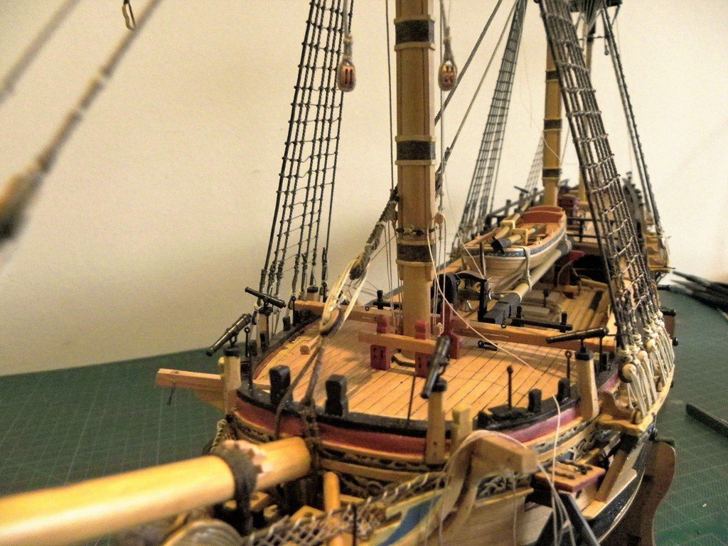
Main Yard completion The yard irons are fitted. Studding booms tried for size Truss pendants The fitting of the Main yard truss pendants has proven the most difficult to date. The tackle hooks onto an eyebolt at the foot of the Main mast. Access is inhibited by the boat on the gallows, the Brake pumps at the mast side, and the Fore winch bar of the main pumps behind which the tackle has to be fed. Add to this that the main yard arms inhibit getting close to the job whilst wearing an optivisor. At least I could remove the boat and spars as one unit, and the Brake pumps can be lifted off their mountings. Main Jeers. 7" line (0.9mm) (4)12" double blocks ( 4.76mm) (2)hooks, 72' 0f line.(13.5" to scale) Rigging the Jeers tyes is fairly pain free, but the same can't be said of the tye falls. Tye falls 2½" tackle line (0.30mm) 180' of line (33.75" at scale) Belaying the tye falls proved equally as frustrating when it came to feeding the line end thro' the Bitt sheaves. These are all but hidden behind the Pump casings with the Quarterdeck overhang above. Much earlier in the build, anticipating the problem, I had threaded line thro' the Bitts with the hope that I could attach it to the tye falls and pull them thro' for belaying. The slight thickening of the spliced join prevented passage and in the end I had to resort to paring down and stiffening the line point, which after some 90 minutes of frustration I managed to get thro'. The moral of the tale make the sheave holes oversize to accommodate the line. B.E.


-
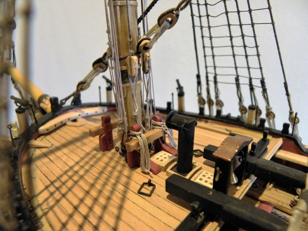
Rigging the Fore yard Jeer Tye falls. For the falls 160' of tackle line is required scaling to 30" of line. I have used Syren 0.20mm line for the falls A 5mm double block is stropped with a hook and the falls line is attached. Much easier to rig the jeers tackle as the eyebolt is much more accessible at the foot of the foremast. The excess line is fed thro' the inner of the bitt sheaves and is belayed. I made up separate coils to drape over the Bitts. All the elements are visible in this shot, the Jeer falls, the truss falls, and the Topmast stays. Note the span shackles in the deck for the fish davit. This completes the rigging around the foremast for the present. I will now move on to rig the Main and Crossjack yards. B.E.

-
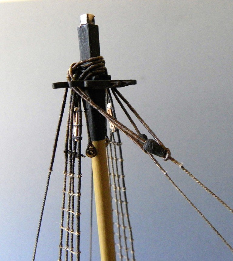
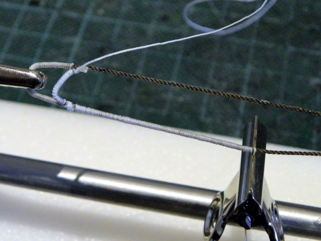
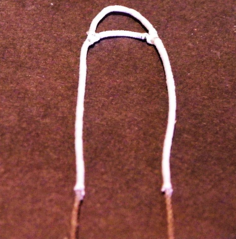
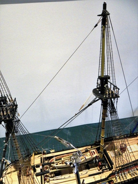
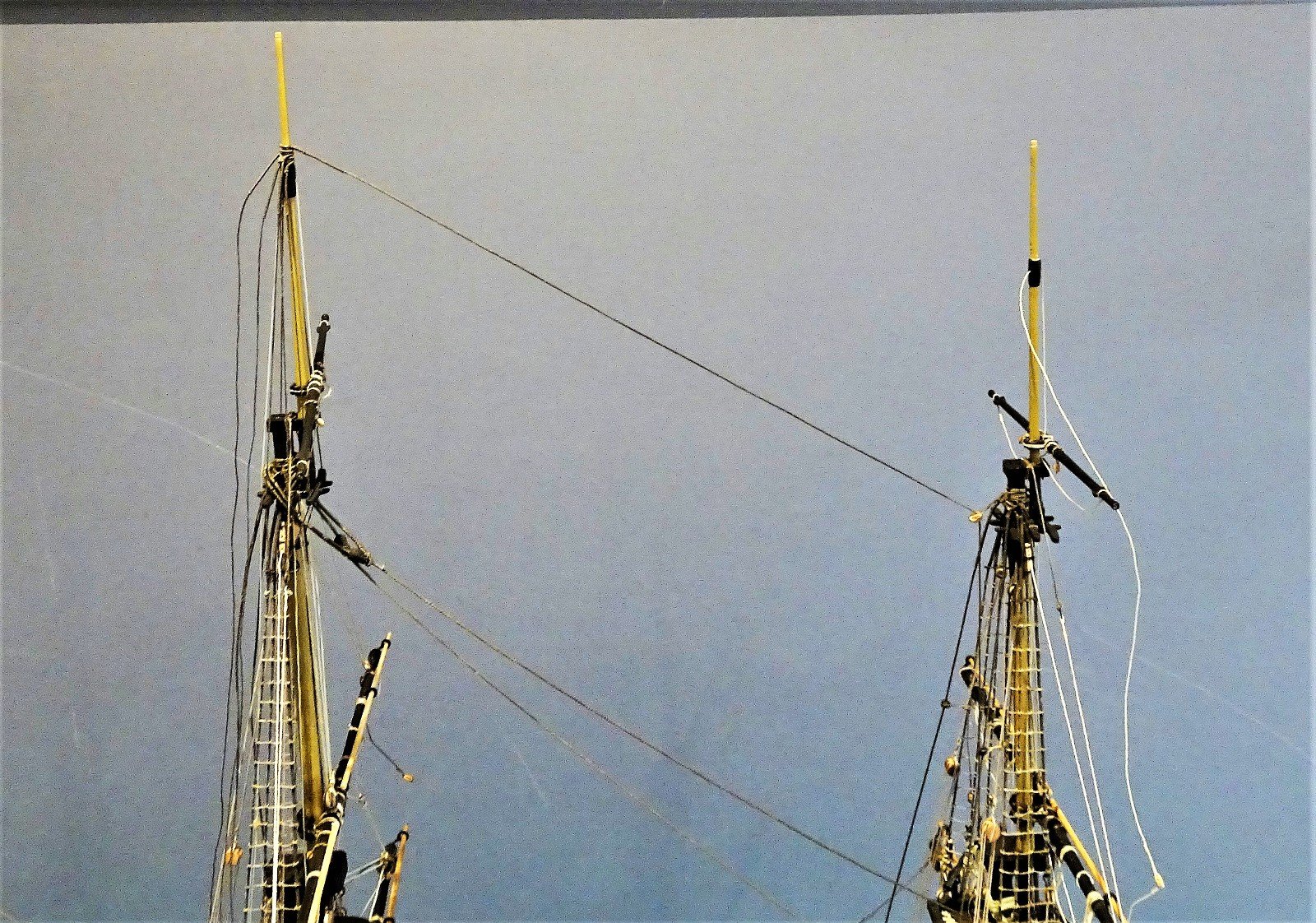
Main topmast backstays 4½" line(0.57mm) For this I am using Morope 0.6mm. The interesting feature of the backstays is the 'D' shaped splicing arrangement where it fits around the masthead. Forming the 'false' splice The bar is served with a good length of excess serving line which will used to cover the required length down the stay. With the 'bar' ca'd to the stay the individual legs are then served. The unstained served stay. The completed stay on the masthead, any imperfections in the serving join will hopefully be covered by the stay collars of the Topmast stays. The backstays will not be fastened off until much later in the build to allow for better access. One point to note with backstays is that the kit allows for two pairs of Main Topmast backstays and has the number of deadeyes along the channel for this. The ffm has only one pair of backstays indicated for the main Topmast. I had slipped betwixt two stools here and had to retro-fit an additional pair of backstays to the Main Topmast. B.E.
.JPG.bc21c1a4856dcac339a68bd13bad3273.JPG)
-
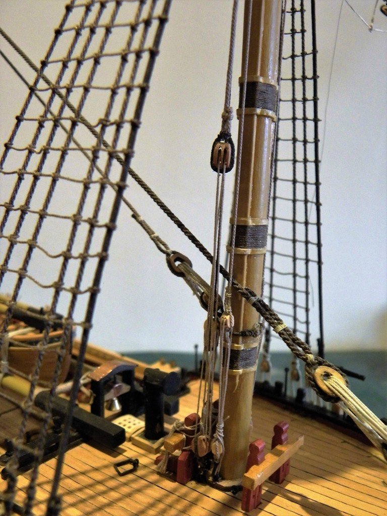
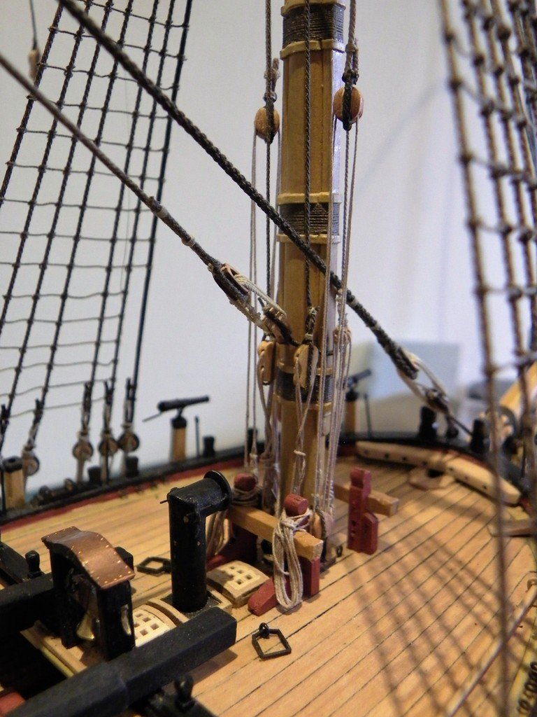
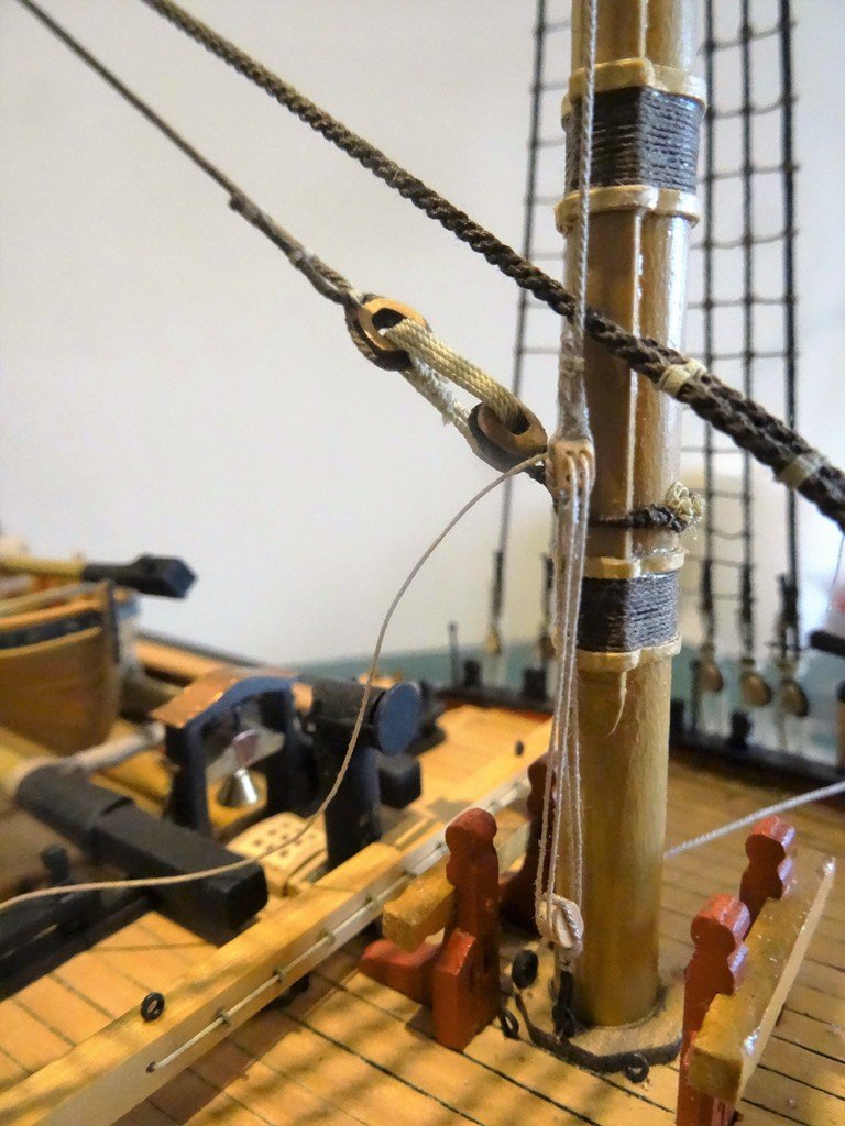
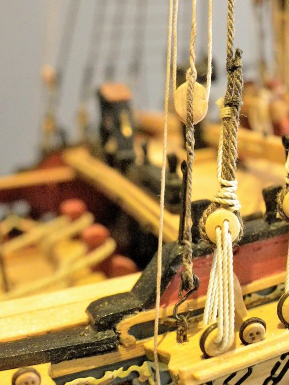
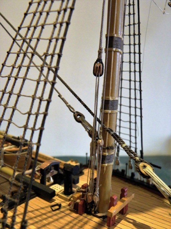
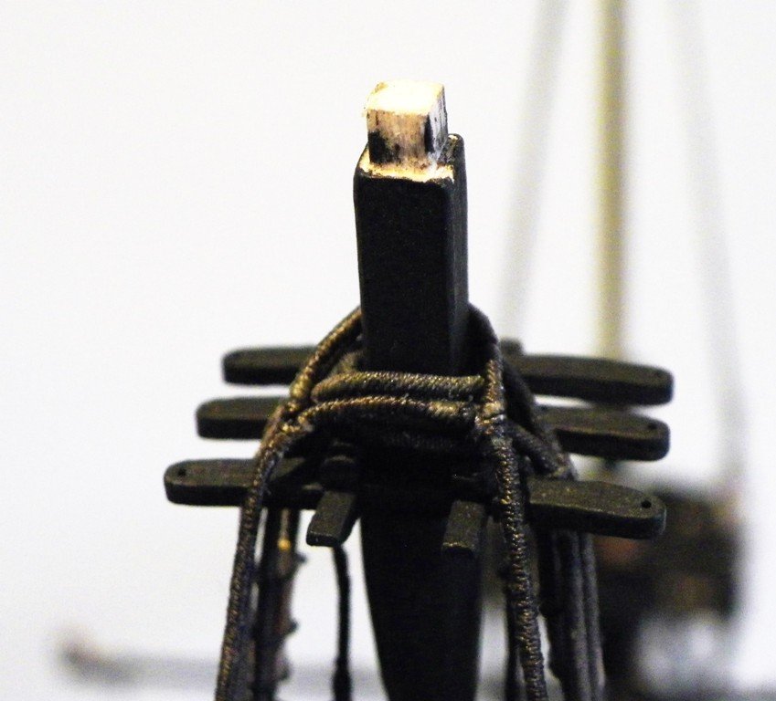
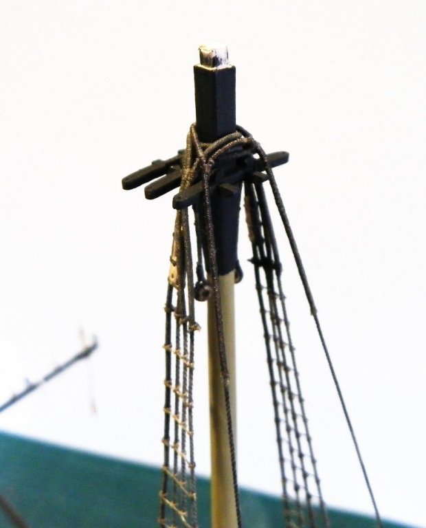
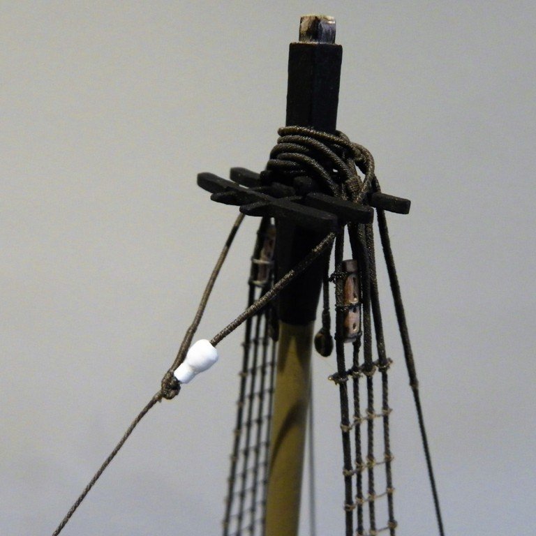
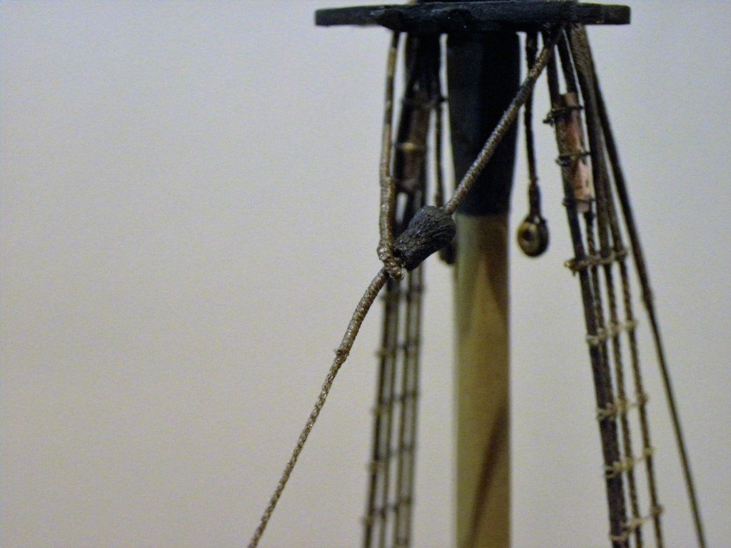
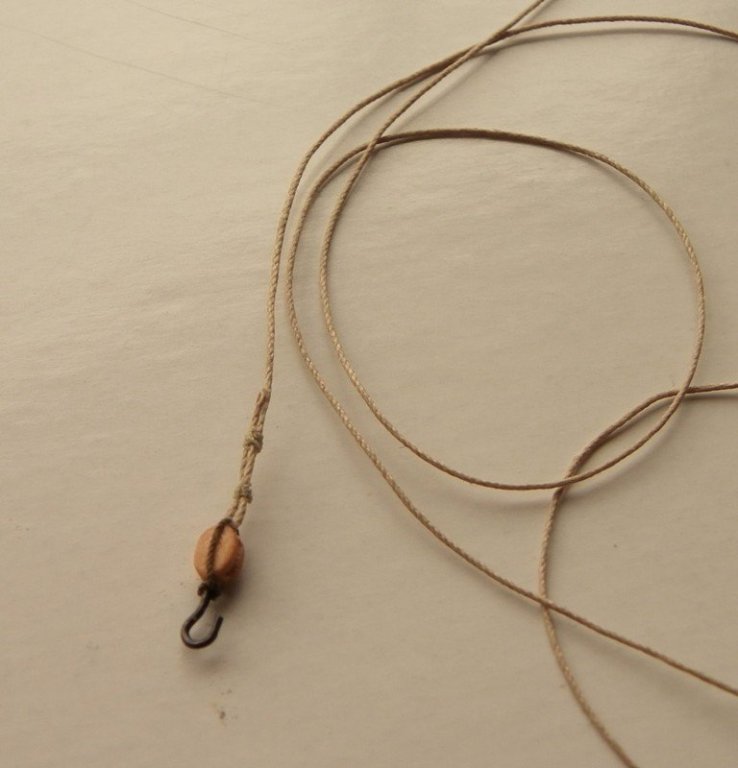
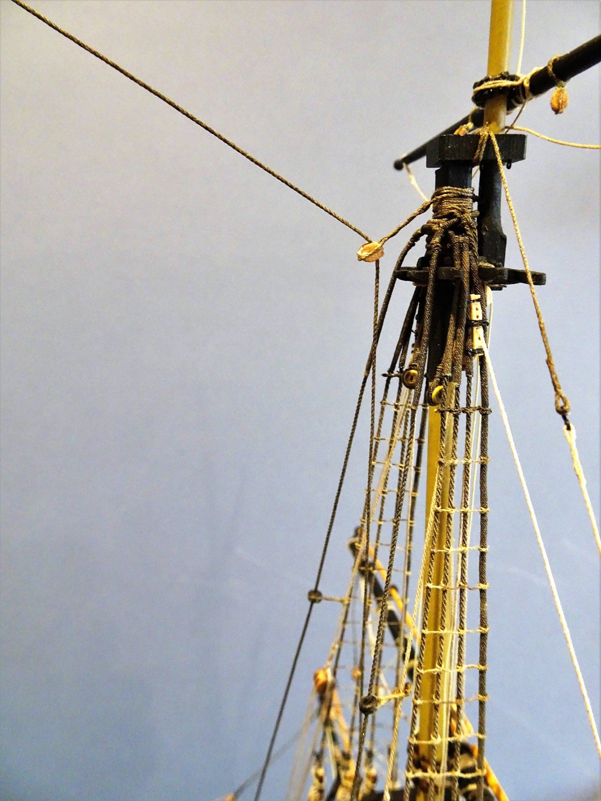
Main Topmast stays Having fitted the Foreyard truss and jeer tyes I can now return to the topmast stays. Topmast Preventer Stay Starting with the Preventer stay that lies below the topmast stay. The lead block for this stay which attaches to the Fore mast below the hounds was covered earlier. (p92) Requirements. 4" line.(0.50mm) 14" long tackle block.(5.55mm) 7" block (2.77mm) with 3" strop(0.38mm) hooked to port side of the mast tackle 2½" line (0.30mm) 0.45mm Syren line has been used for the Topmast Preventer stay. A mouse has also to be fashioned for the stay, my method is covered on p85 so I won't repeat it here. Trial fitting the position of the mouse. ..and the completed mouse after 'treatment' With the stay fitted around the masthead it is lead thro' the lead block beneath the Foremast hounds and the Long Tackle block is seized in. The other half of the tackle, a 3mm single block, has a hook fashioned from an eyebolt ca'd into the base, around which the strop is secured. The tackle line (I have used Syren 0.20mm line) is secured thro' the strop at the top end of the block. This is a little simplification but the space between mast and bitts is very tight and the detail won't ultimately be visible. Trying to catch the hook on the eyebolt proved to be a testy little exercise, as did the hitching the falls, which managed at every turn to snag on each and every fitting of the foc'sle. How many of us with total concentration, having finally got a line threaded thro' an awkwardly placed block pulled on the end with a sense of relief, only to find that the excess has snagged on a gun dismounting it from the carriage. At this stage of rigging very soft hands are required, with a pause after each small movement of line to check there is no snagging. Main Topmast Stay 0.63mm Syren line for the Topmast stay. A repeat exercise for the Topmast Stay, just needed to tweak the Fore top rail height to allow a clear run the lead block around the masthead. The completed masthead with stays in position. Lead of the stays. Long tackle block falls of the Topmast stays, Preventer stay to port. (Temporarily secured at present) Note: The Backstays are fitted over the shrouds before the Topmast stays are rigged. B.E.

- 366 replies
-
- 1
-
-
- pegasus
- victory models
- (and 2 more)
-
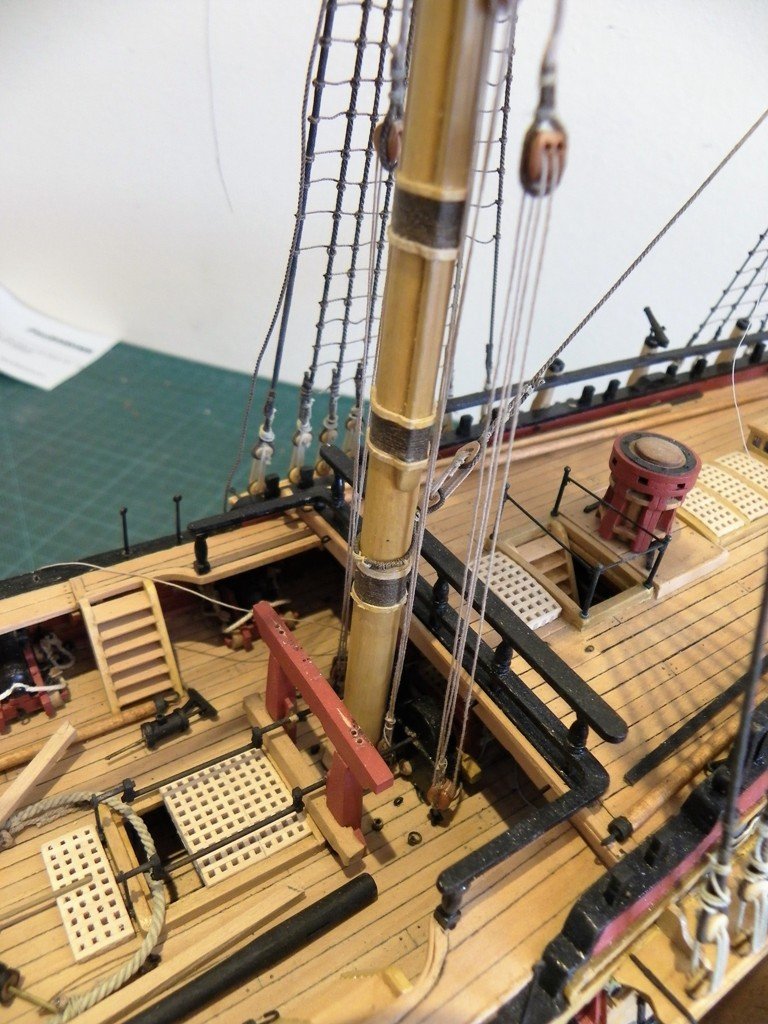
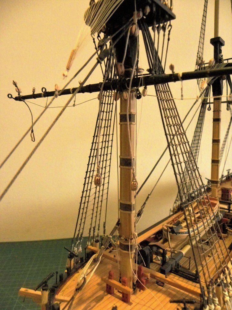
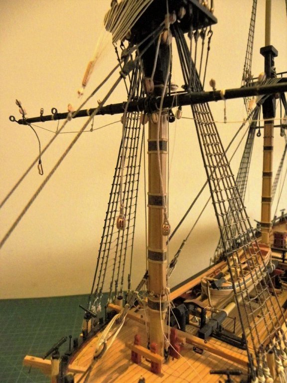
Fitting the Fore Yard I am fitting the Fore yard at this point to maximise the finger space behind the mast to rig the Truss Pendants. Requirements. Small thimbles, (2). 4" line, (0.50mm ). 24' long (114mm). (4) 8" double blocks,(3mm). 2½" strop hooks,(1mm). 2" tackle line (0.25mm). 96' long.(457mm) Attaching the thimbles and pendant line to the yards is fiddly but not difficult with the yards off the model, but fitting once the yards are in place can turn into a very frustrating exercise. There are details of fitting the pendants in the ffm. Lees, and Longridge's Anatomy of Nelson's ships, which I think is the clearer description, and drawing. The truss pendants are temporarily fixed to the eyebolts to mark the point where the blocks will be attached. Fixing the pendant block. Starboard tackle rigged. Next up the jeer tyes 7" line (0.9mm) (4)12" double blocks ( 4.76mm) (2)hooks, 2½" tackle line (0.30mm) Conveniently Syren do both 0.88mm and 0.30mm line. According to ffm 60' (scaling to 12")of jeer tye line is required. This works out pretty spot on. Tye threaded thro' the jeer blocks. Jeer tyes (but wrong side of the yards at present.) This shot shows the completed jeers tyes and truss pendants. Before I rig the Jeer tye falls I will return to fit the Topmast stays. The tackle for these are fitted inside the jeer falls, between the bitts and mast and are best dealt with first. B.E.


- 366 replies
-
- 1
-
-
- pegasus
- victory models
- (and 2 more)


REDMSW.JPG.83f5b05e6b7b79490edf032d5c3104d3.JPG)


.JPG.3f7e65479070b0f453fc82916c414152.JPG)