
.JPG.ca33079f5815b861e67b9c2cccd37982.JPG)

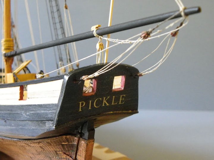
Blue Ensign
-
Posts
4,286 -
Joined
-
Last visited
Content Type
Profiles
Forums
Gallery
Events
Posts posted by Blue Ensign
-
-
Cheers Chris

Anchors
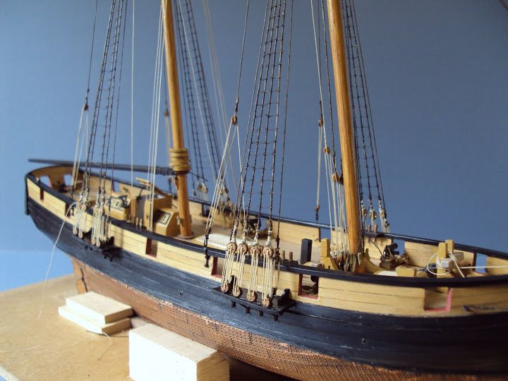
A white metal anchor is provided with the Pickle kit to be fitted on the Starboard side.
I was a little puzzled by this as my research suggested that she should have at least three, two bowers of 6cwt plus a smaller kedge.
I bought a second matching anchor plus a kedge.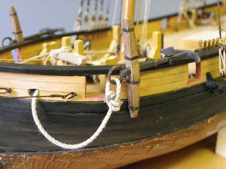
The observant may have noticed the absence of catheads on Pickle, something that puzzled me somewhat.
In my research I discovered that it is entirely possible that catheads were not fitted given the relatively light weight of the anchors, and that a Fish tackle from the Masthead was used to raise the anchor.
I may still yet fit one of these to demonstrate the principle.
The stocks of the anchors required some fettlin’ to obtain the correct shape and I wasn’t happy with the given dimensions of the anchor rings.
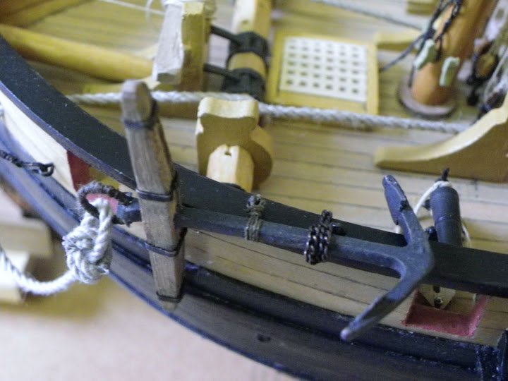
The ends of the anchor stocks have been rounded off in accordance with practice of the time.
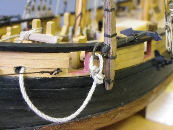
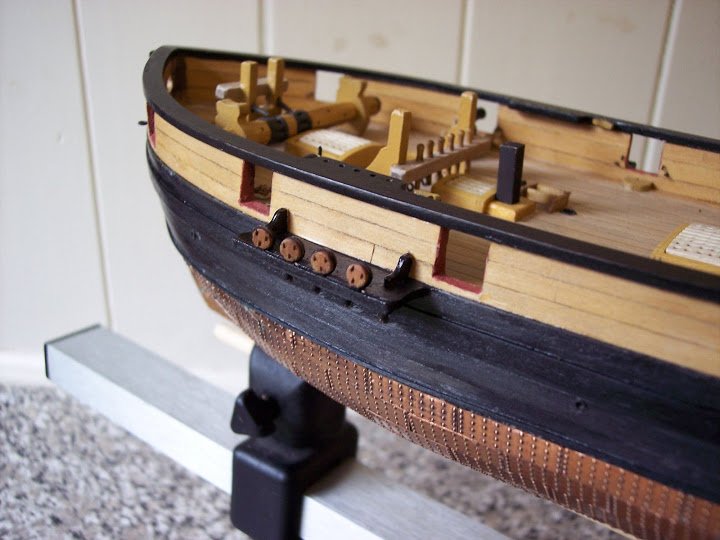
The use of an inside clinch to secure the anchor cable can be seen here. I was tempted to use a Fishermans Bend, an interesting knot, which was sometimes used on smaller anchors, but decided in the end to stick with the clinch.
Jotika suggest that wire is wrapped around a 6mm dia dowel to produce the rings, but this looked out of scale to my eye.
As with everything naval, anchor proportions were subject to specific rules, the ring diameter on small anchors is something in the order of 1/8th of the length of the shank.
This is 33.15mm so the anchor ring should be in the order of 4mm.
After clean up the anchors were painted with humbrol iron grey rather than black, gave a better scale effect I thought.
For the iron stock bands Jotika suggest using strips of black cartridge paper,I preferred to use the brass etched framing from their eyelets as the banding.
1.3mm line is supplied for the anchor cable; I checked this against known formulae - ½” circumference of line for every foot of maximum hull width.
This did indeed work out at 1.3mm Ø line – well done Jotika.
The anchor cable however is far too white for my taste ; I rather thought it would have a sort of greyish appearance so I soaked it in ‘dirty’ water to dull it down.
The anchor is secured to eyebolts fixed atop the rail with thread.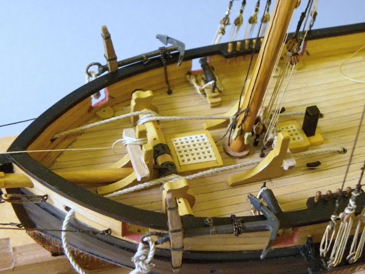
I wasn’t sure about the authenticity of this so I modified the lashing using 23 links to the inch chain to secure the one fastening with chain secured with a rope lashing to a ring bolt in the deck. The second lashing was line secured around the capping rail eyebolt.
The effect I was after with the anchors was a slightly worn/weathered appearance, and to this end I am satisfied with the result.
The Kedge
This is lashed to the Starboard aft bulwark on the Naval Museum model, Jotika did not include one with their kit.
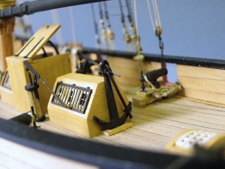
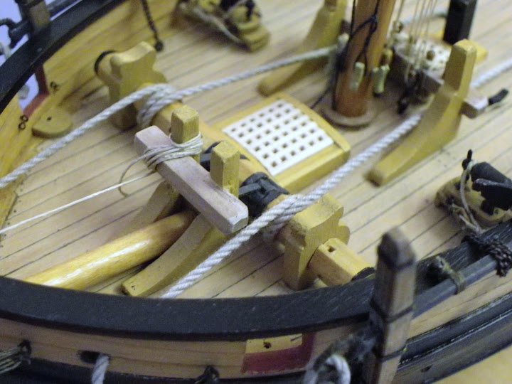
No historical evidence for it but I rather fancied securing it to aft face of the skylight, seemed a reasonable place to store it.
B.E.
-
Launch cont'd
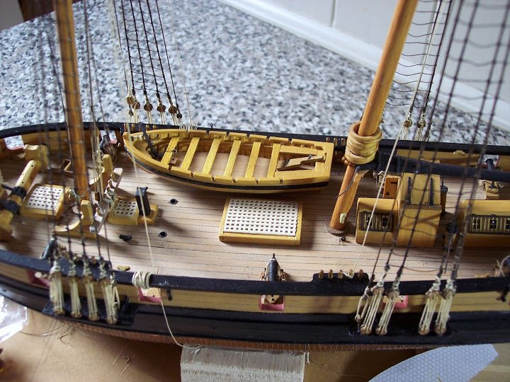
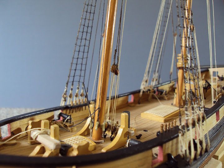
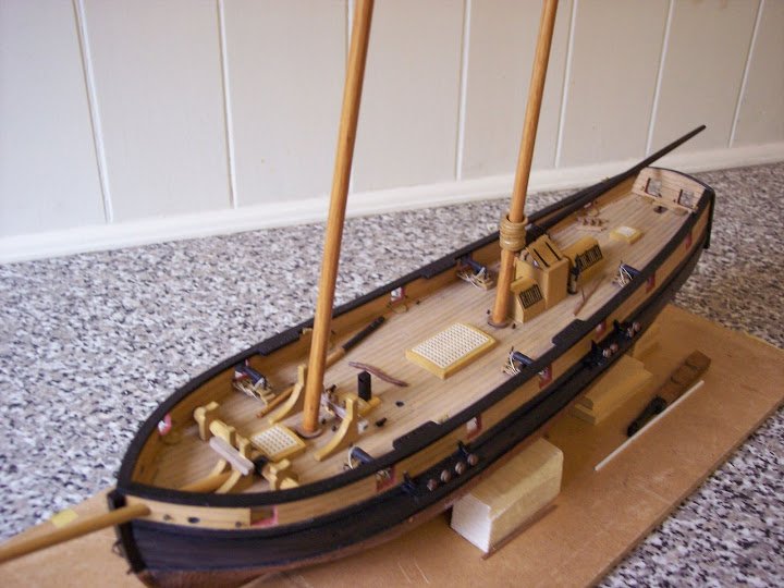
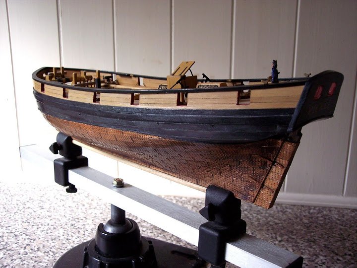
Jotika only provide two half chocks to support the boat, the inference being that the boat is supported on the starboard side by the Pickle’s bulwark.
This seemed odd to me so I fashioned a pair of full chocks on which to rest the Launch.
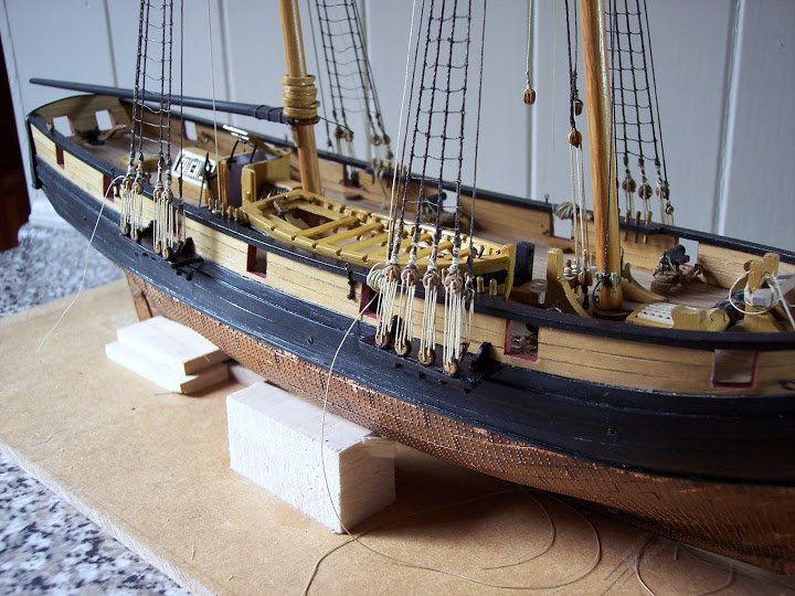
Having spent a fair bit of time making the bally boat, I’m now not sure I like it - hmmn I think I will have to ponder on that.
I certainly think I will only display one boat on the deck even if I decide to go ahead.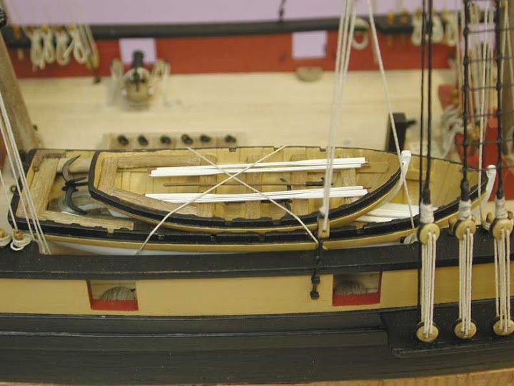
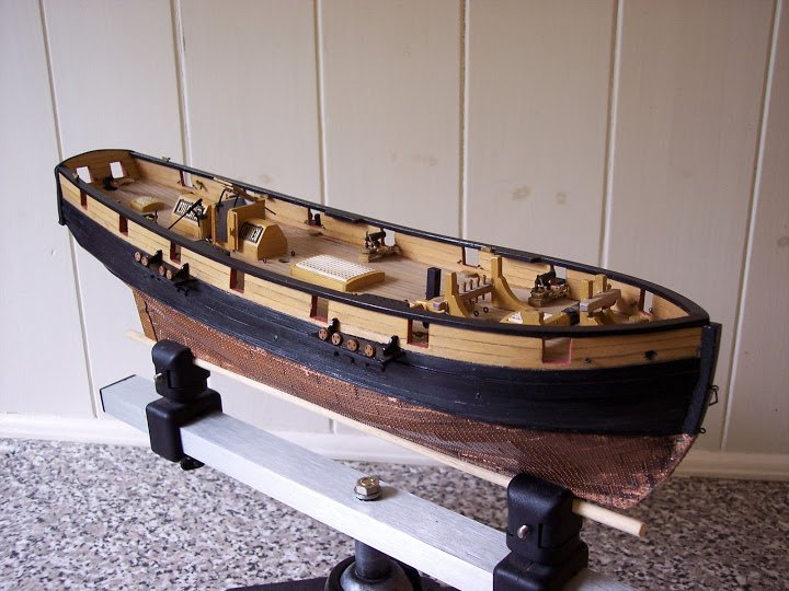
The kit arrangement.
How would they manhandle a boat of that size outboard given the rigging incumbrances.
I've a fair idea of how the boats were swung in and out, using a triatic stay slung between the two mast pendants, with tackles attached to ring bolts within the boat to raise it above the bulwarks, further tackles slung from the yardarm, and probably the Fore gaff, to swing it out.
Can you imagine how tricky that could be with an overlarge ships boat, keeping it steady to avoid crashing into the rigging, or worse the masts, she would have to hove to in any case to launch a boat, but in anything other than a millpond sea, she would still be rolling and pitching to varying degrees.
I really wanted to display a boat on the deck, maybe a replacement cutter of slightly less size, and some modifications learned from the building of the Launch.
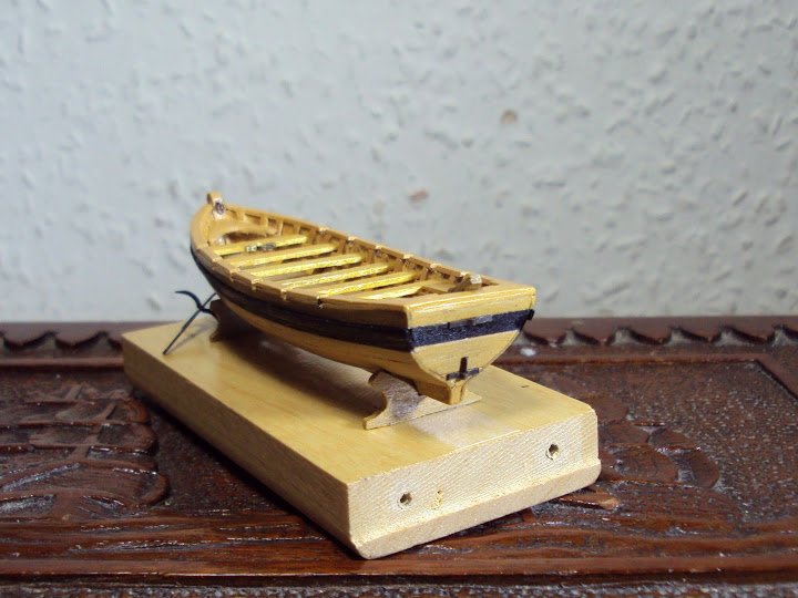
The 14’ Cutter
This is not a bad shape and at least I know it will fit on the deck without giving the impression of trying to squeeze a quart into a pint pot.
I took a different approach with the Jolly boat.
Exterior planking was done clinker fashion using strips from computer label paper.
I decided that planking the inside of the hull was a waste of time as the planks were hardly visible on the larger boat when finished, and they just add to the thickness of the gunwales.
On this boat I used styrene strip of 0.5 x 1.5mm for the ribs and keelson, 0.5 x 2 mm for the rising plank.
The gunnels I made from 0.75mmx1.5mm styrene strip.
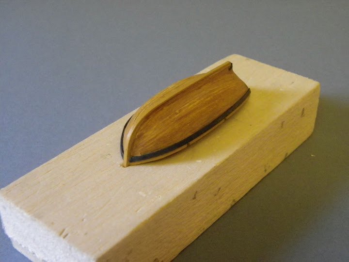
Small boats are tricky to hold whilst working, but a cut out in a block of balsa goes a long way to keep it steady.
To avoid unnecessary thickness I left the ribs long so that they would support the thin gunnels.
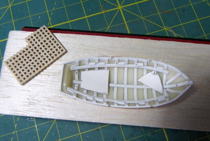
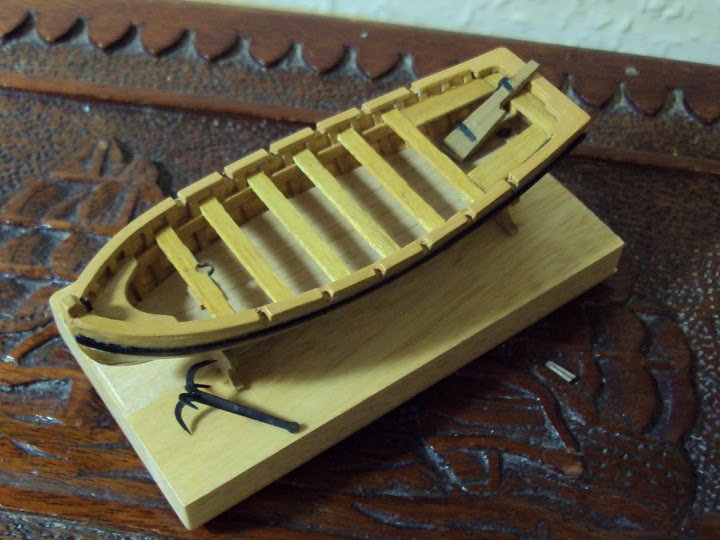
Basic internal structure completed, paper patterns for the foredeck and stern sheet gratings
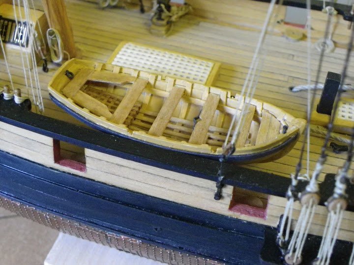
Jotika suggest that there were no bottom boards or knees, but I have modified the interior to reflect the drawings in the McGowan Victory book, and other reference sources.

Bottom boards have been fitted, a grating in the stern sheets, and a small foredeck at the bow. The gratings which are nice features in small boats were left over from the main build but necessitated taking down to a fraction of their original thickness to suit.
Boxwood strip was used for the thwarts and ring bolts fitted at the bow and stern.
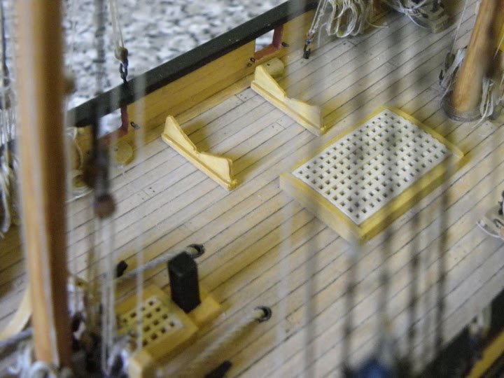
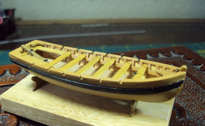
Modified chocks.
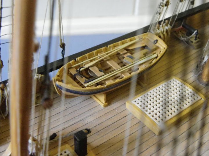
In keeping with the muted colours of the main model I decided to colour the oars in a natural wood finish, white looked too stark to my eye, and there is no white anywhere else on the vessel.
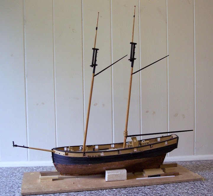
She certainly looks more in scale to the size of Pickle, so the 19’ launch will not be displayed on the model.
B.E.
- CharlieZardoz, Gregor, Stoyne and 2 others
-
 5
5
-
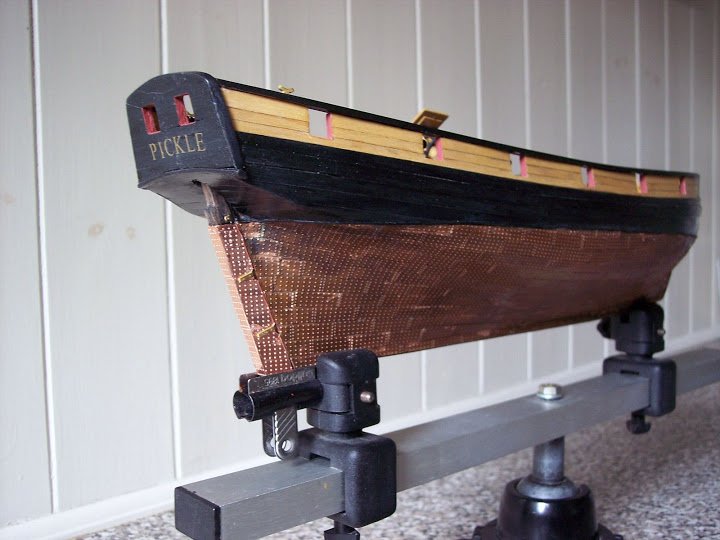
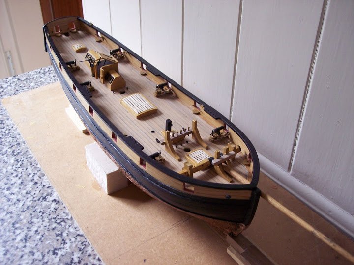
The Pickle Boats
Jotika have provided two boats, a `19’ Launch and a 14’ Cutter or Jolly boat.
I rather think that a cutter would be more likely than a Launch in such a small vessel, but whatever, the 19’ boat is shaped more like a Launch, whereas the jolly boat is more definitely a cutter shape.
Two boats would seem to be the right complement for the Pickle, but I would have preferred it had Jotika supplied an 18’ cutter rather than the launch. I do know that Pickle carried two boats, a cutter and a jolly boat, why Jotika went with a 19' Launch I don't know.
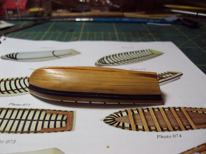
Provided are blank resin hulls; black cartridge paper is provided to make and represent the ribs. The hull is supposed to be simply painted with the application of walnut strip to make the thwarts and strakes etc.
These are the basic hulls.
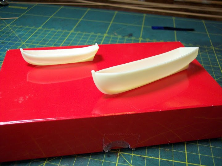
The idea of cartridge paper for the ribs did not really appeal, and I decided to use styrene strip for the interior framework. I also wanted to reflect the planking on the inside but without adding too much to the thickness.
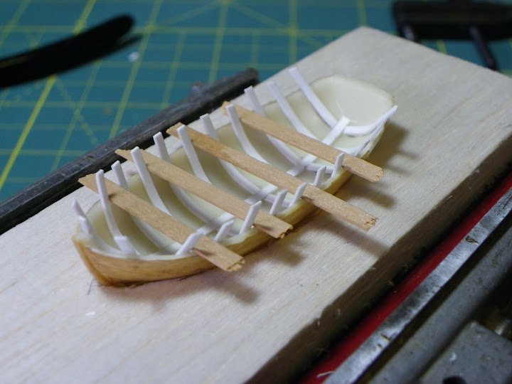
First off a keelson was laid down the centre using 1x1.5mm strip.
To represent the planking from the inside I used strips of good quality printer paper stuck down with pva. Over this are fixed the ribs of 0.75 x 1.5mm styrene strip.
The ‘paper’ planking was coated with a light oak water based varnish with a touch of Caldercraft yellow ochre w/b paint added.
Several coats later and a topping of Caldercraft Flat- Matt varnish, this is the result.
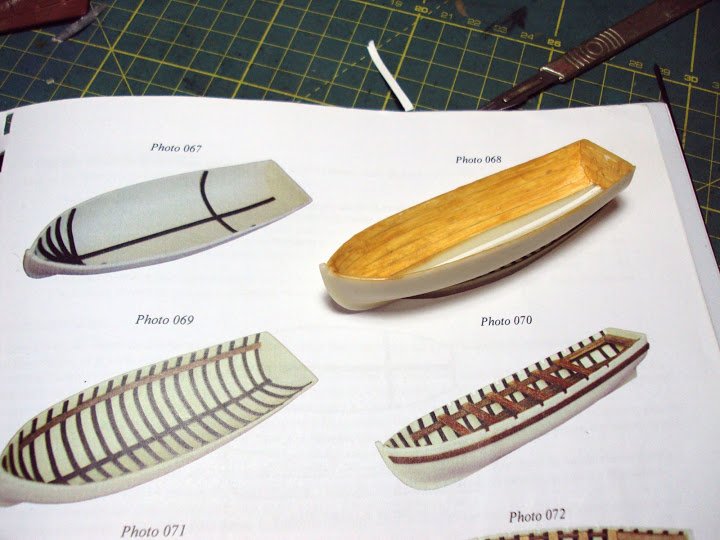
The planking lines are apparent and the desired effect achieved.
Much of it will be covered by the ribs and other internal fittings, and final finishing will be done once the ribs are put into place.
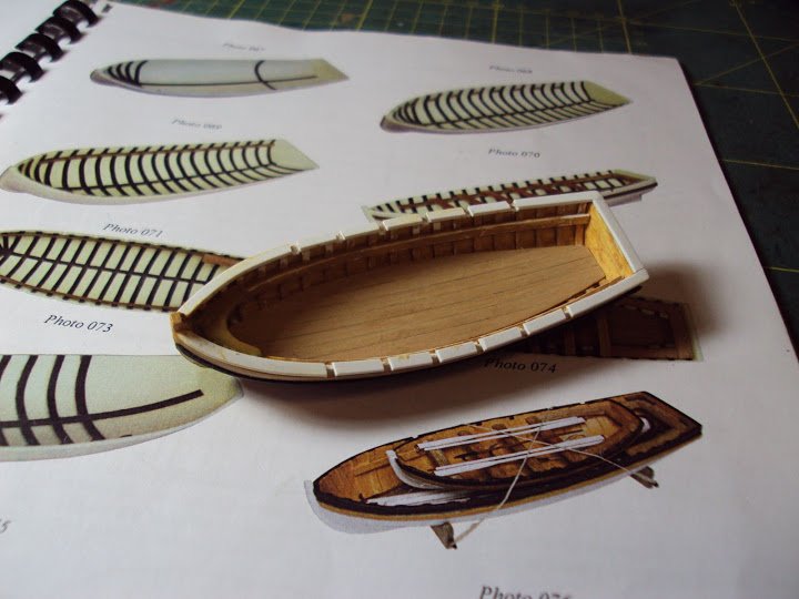
Next the ribs of 0.75 x 1.5mm styrene strip are added.
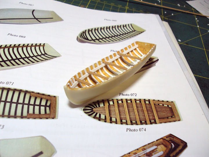
Here all the ribs are in place and the Rising Planks on which the thwarts rest have been fitted. A simple depth jig was used to check that the rising planks were the required 3mm below the top of the sides along the length of the hull.
Temporary thwarts are in place to check the levels across the boat.
If you’re not a purist, I am certainly not, styrene strip makes excellent internal small boat structures, although had the boats been of all wooden contruction I would have put in the extra effort to replicate the ribs etc in boxwood strip.
Still at the end of the day, it’s how the finished article looks and how far it fulfils a modellers satisfaction levels.
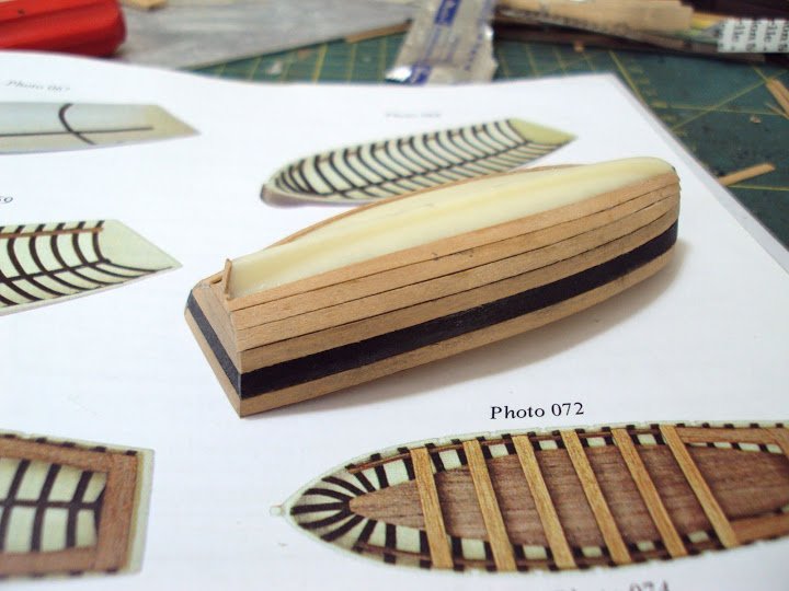
To reflect the finish of Pickle herself, I planked the outside with 2.5mm boxwood and ebony strip, applied with ca. I wanted to continue the theme of as little paint as possible so the hull will be left natural.
The bottom boards or footwaling.
Jotika provide a ply template for this over which boarding is stuck.
The bottom boards are butted together and run the length of the boat. This accords with the fittings of many Launches of the period. Boxwood strip rather than the provided walnut was used. The only addition, a step to take the mast, and a ring bolt at the stern.
A 0.75x2.5mm styrene strip capping rail was fitted, into which the rowlocks were cut, I also took the opportunity to fit a breasthook.*
*( A breasthook is a wooden knee to add strength to the bows, no ship’s boat should be without one)
When I tried the Launch/cutter on the Pickle deck it seemed to take up an inordinate amount of room, looks like it would have been a tricky exercise getting the boat over the side avoiding the shrouds and stays.
The backstays and vang tackle are not even fitted at this stage.
to be cont'd...
B.E.
-
Very nice log B.E. You have alot of information here that will benefit all. Thanks
Frank
Thanks Frank, for looking in on my build, I'm pleased you like it
Great information and detail of your research as well as a terrific build, B.E.
John
It great to receive such positive comments from yourself John, thank you so much.
Masterful job!!
The Pickle is on my waiting to start kit shelf. I know I will be referring to this log often when I start her.
I'm still thinking of not coppering the hull and going with something other than the stock walnut for the second planking. I love the look of wood, and have just not been a coppering guy. That being said, your coppering job is great.
Thanks for sharing.
I don't think you will be disappointed with Pickle bcd, the build gave me a high satisfaction level, and it was my hope in posting this log that it would assist and encourage other to take her on. Thank you.
-
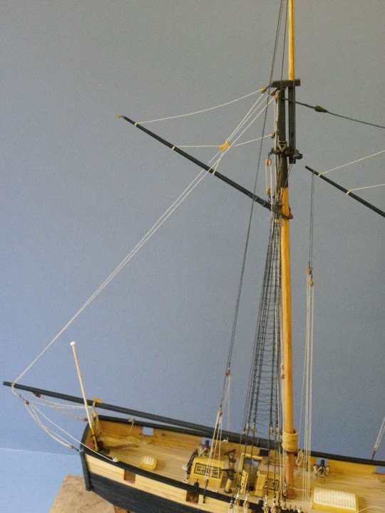
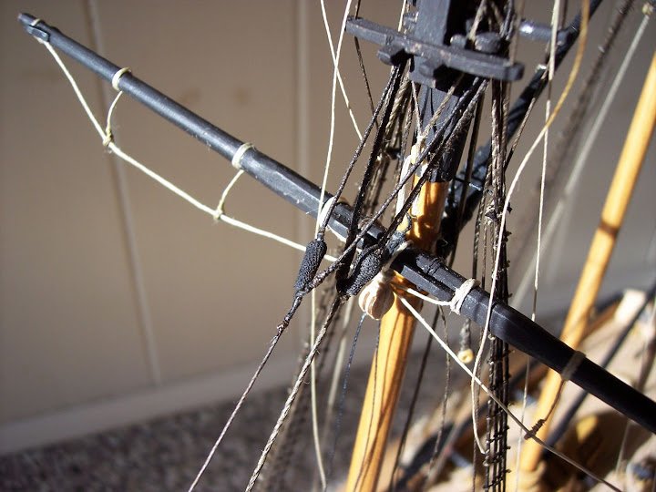
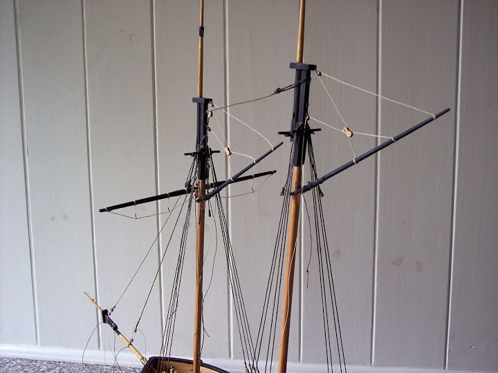
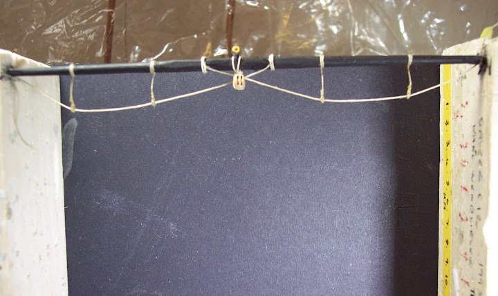
The home straight – Rigging the Square yards.
This is quite a simple affair (I use the term loosely) on a schooner such as Pickle consisting of Lifts and braces for the Spread yard and Topsail yards, and sheets and clew lines for the Topsail.
I made life somewhat more difficult for myself by not pinning the yards to the mast as suggested. As far as possible I prefer to have the yards free to move around.
One outcome of this and a niggle that has caught my eye for some time is that the spread yard had been pulled out of the horizontal as determined by the sling and stop cleats. The culprit is the yard sling and the pull of the single Truss pendant.
To put matters right I had to cut the lower sling thimble from the yard and re- seize it once the yard had been adjusted.
Without yard pinning a tension balance has to be achieved between all the lines to hold the yards secure, and this entails loosely fitting all the running rigging and then tightening it by degrees.
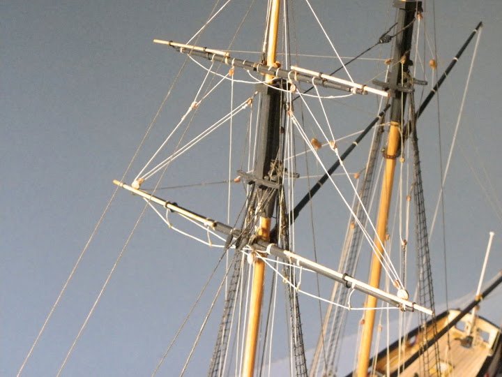
Once done the yards are held quite rigidly.
Although for one or two lines I have fitted traditional looped and seized belays to the pins, I wanted the main working lines to be loosely draped over the pins as in a working situation.
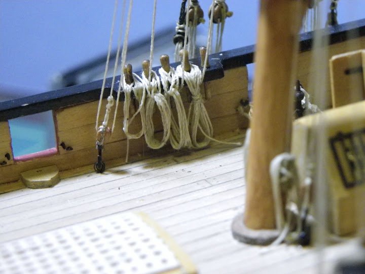
The coils were made separately, fitted over the pins and draped into shape using diluted pva.
Two things I should have done earlier in the build is attach the pendants and blocks around the Main masthead to take the topsail braces, failure to do this resulted in an exercise of frustration trying to seize the pesky things between the masthead and topmast at the doublings.
Moral of tale double check that all necessary attachments are made before starting rigging.
Jotika show brace pendants fitted to the crossjack yard at 60mm in length., when fitted they looked a little long to my eye.
I also pondered whether the fitting of brace pendants was appropriate at all, by the time of Trafalgar they would be somewhat dated.
Still I decided to go with them, they add a little interest if nothing else, but according to Lees, brace pendants should be 0.3 of the respective yard in length; this would give an overall pendant length of 52mm.
The braces are the last kit rigging item to be fitted, and quite a tricky one at that. Equalising the tension between the opposing braces to ensure that the yard is not pulled out of line, or indeed the shroud with the lead blocks attached, makes for slow progress.
With braces I rather like a degree of slack in them, but the set up of the running part of the braces make it very difficult to achieve a realistic look; with brace block on the yard the situation would be different.
Note to myself:
Don’t rig the fore gaff vang tackles before fitting the belay coils for the braces, the bally things are perfect snag magnets, and are best done after the other coils are in place.
I have noticed that since fitting, the footrope stirrups have developed a little curl, something I don’t like.
I have tried to remedy the situation by hanging weights on the footropes and stiffening the stirrups with neat pva, only time will tell.
So folks that about does it for the rigging, unless the mood takes me to fit one or two extra lines not covered by the kit, but I am conscious of the fact that this model will not be cased so too much top hamper will get in the way of cleaning.
Now what to do about the boats.
B.E.
-
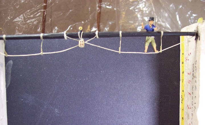
Rigging the boom
I have a couple of issues with the Driver boom, one is the absence of sheets, and the other the form of the Topping lifts.
Jotika make no mention of sheets, but every driver boom I’ve ever seen has them rigged.
They were quite heavy tackles consisting at scale of a 4mm double and 3mm single block with falls of 0.5mm dia line.
These were fitted along with a boom cleat to secure the block.
The Jotika method of rigging the Topping lift which is single, is to seize it around the boom end, pass it up thro’ the port sheave of the double block at the masthead cap, thence down towards the deck where a tackle is attached, and belayed to the mast cleat.
There are different ways of rigging topping lifts, and a single version was used in fair weather but I can’t quite believe that Pickle battling the Atlantic wouldn’t have used double lifts.
I have gone with a standard approach of twin lifts middled around the boom with a clove hitch, each end passing thro’ a single block strapped around the masthead, thence to the deck with tackles attached, as per the Jotika suggestion.
For those who may think yes, but the gaff is trapped between the topping lifts, in reality the lee lift was slackened off when sailing.
In setting the boom it is important that it clears the head of the Helmsman, Dick here checks that all health and safety obligations are complied with.
Bits and bobs inside the Transom – things I should have done earlier.
Apart from the stern gunport eyebolts the transom according to the Jotika plan is quite free of fittings.
Because I fitted a boom sheet an eyebolt and cleat were required, and because I fashioned an Ensign staff, a tabernacle and halyard cleat were also required.
These would have been easier to fit earlier in the build before the boom was fitted, but the additions were achieved without too much trauma.
A coat was also made to fit around the rudder head using my old standby micro- porus tape. This is not to be confused with the rudder coat which is fitted beneath the transom where the rudder enters the hull.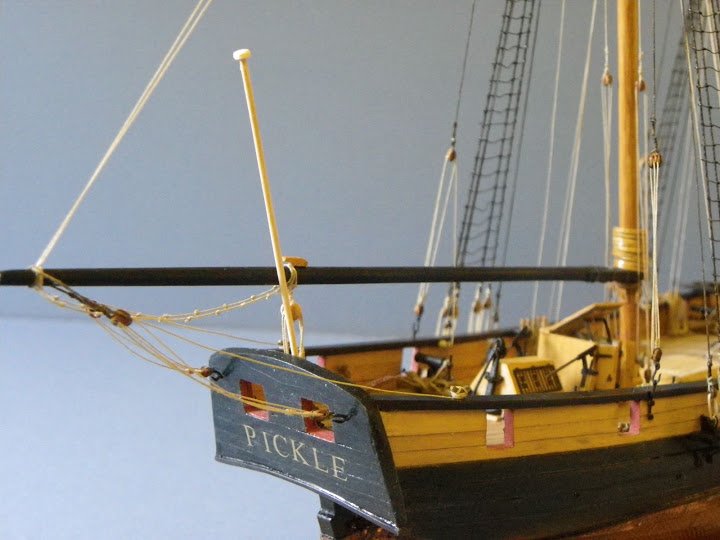
Boom horses were also fitted, I can’t understand why Jotika omitted these fairly common aids to working on the boom.
Guy pendants and tackles are last item to be fitted.
I finally made the decision to secure the Kedge anchor to the skylight framing.
Onto the Square Yards, and then some tidying up.
B.E
-
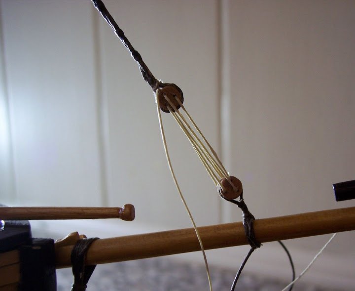
The final bits of Standing Rigging
Now that the stun’sl booms have been sorted I can rig the Topmast Backstays and Main T’gallant stay.
Jotika suggest 0.25mm line for the backstays, but I consider they should be the same thickness as the Topmast shrouds, so I have gone with 0.5mm line. The tackle lanyards are of 0.25mm line as suggested.
Note:
The kit instructions suggest that the Fore T’gallant stay and Main T’gallant stay be fitted before the Topmast backstays.If this is done the backstays will have to be fitted insitu, with more difficulty in getting a neat seizing and with attendant tired arms.
It’s much easier to form the backstay eye splice off the model and slip it over the masthead before fitting the T’gallant stays.
A bit of work in rigging these backstays, they end with a double block thro’ which a tackle is rove from a single block with hook that is attached to the backstay plate before belaying on bulwark cleats.
A lot quicker to write it than do it.
Attaching the blocks to the ends of the stays is an exercise in frustration, the same method has to be applied as with deadeyes, but without the nice groove around the block they take every opportunity to escape the noose of the stay.
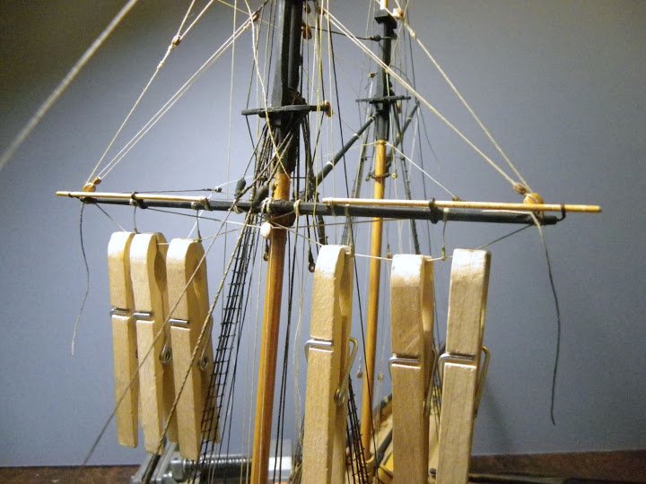
Now the backstay tackles and Fore Gaff Vangs are in place there is even less room to swing a 19’ Launch, just about get the Jolly boat over the side without fouling the rigging.
All the loose tackles have now been belayed at the foot of the Fore mast.
The black lines attached to the cleats at the mast foot are temporary, to hold down the Crossjack yard against the pull of the lifts until the Topsail sheets are rigged.
One of the penalties of not pinning the yards is that they flop about until stabilised by the opposing forces of the completed rigging.
The Crossjack yard lifts are seen here rolled on the yard; I won’t fit them until I have the sheet blocks fitted so that I can balance the two.
The next phase will see the rigging completed.
B.E.
- Small Stuff and dafi
-
2
-
Messing about with Studding Booms
In my never ending quest to make my models different from what is supplied I rather belatedly thought about adding Studding (Stun’sl) booms to the model.
These are not supplied by Jotika, but my research suggests that they would have been carried by Pickle.
The Booms themselves are not a problem, sanded down from 2mm lime dowel to something a tad over 1mm Ø .
It is the yard irons thro’ which they pass that presents the difficulty, particularly as a retro fit, something I would not recommend.
I decided to make the Crossjack yard irons out of slices of Styrene tubing and the boom iron out of brass eyelets.
Here’s the result.
Completed irons in place.
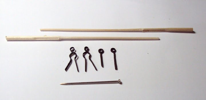
Boom irons and booms for the Topsail Yard
For the yard irons I used the edging frame of the brass etched eyelets supplied by Jotika.
I have mentioned it before but these brass strips have a multitude of uses from hinges, brackets, strappings, Pintles and Gudgeons, and of course yard irons.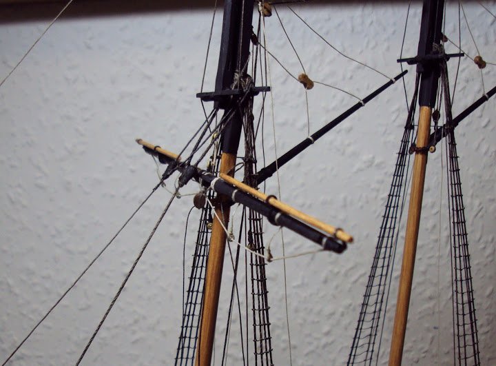
Cro’jack yard booms in place.
Topsail yard booms.
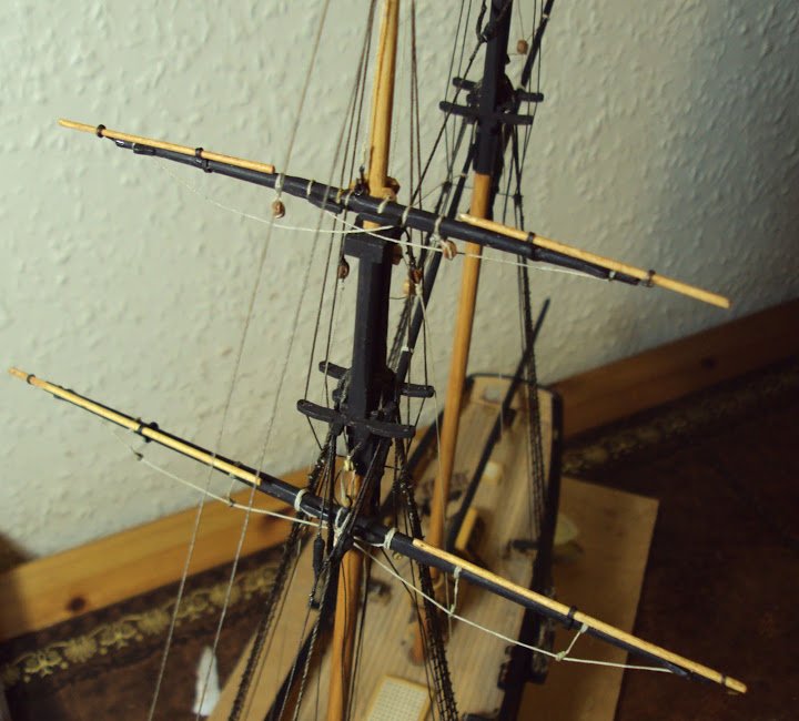
The completed set up, apart from the lashing of the booms at the inner end.
The Stuns’ll booms have simply been coated with brushing wax.
A good mod I think, the naturally varnished booms contrast nicely with the black yards.
I can now get started on the Running rigging.
B.E.
-
A Rattlin’ good yarn or yet another step backwards
According to the plans only the first three shrouds are fitted with ratlines both on the Fore and main masts.
Jotika specifically mention that the fourth shroud is a backstay and was never fitted with ratlines.
So I proceed on this basis, even so with a little niggle in the back of my mind. By the time I had rigged twenty or so ratlines I thought I don’t like the look of this and on a practical level there is insufficient room to allow the climbing of the mast even by one crewman, let alone several if attention was required in a hurry.
Of course towards the top the shrouds narrow considerably, and they’re not that wide to start with.
Nothing for it I summoned ‘Dick’ and he in turn sent old Tom aloft to check things out.
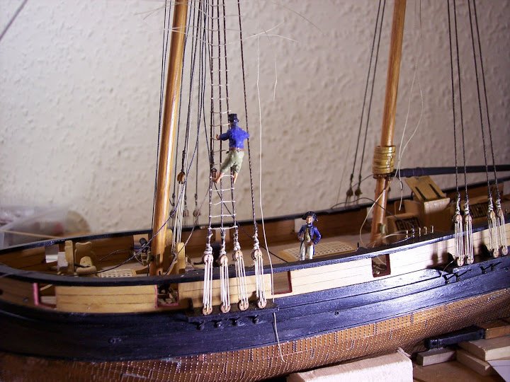
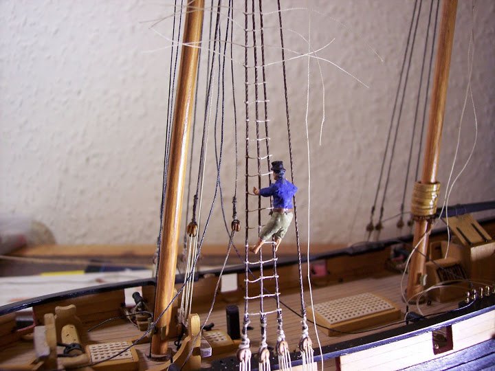
My point proven I think, poor Tom has to hang onto the ‘backstay’ as Jotika call it to assist his climb. As the shrouds on Pickle consist of two pairs each side, to refer to the last shroud as a backstay seems questionable, it’s a shroud by any other name.
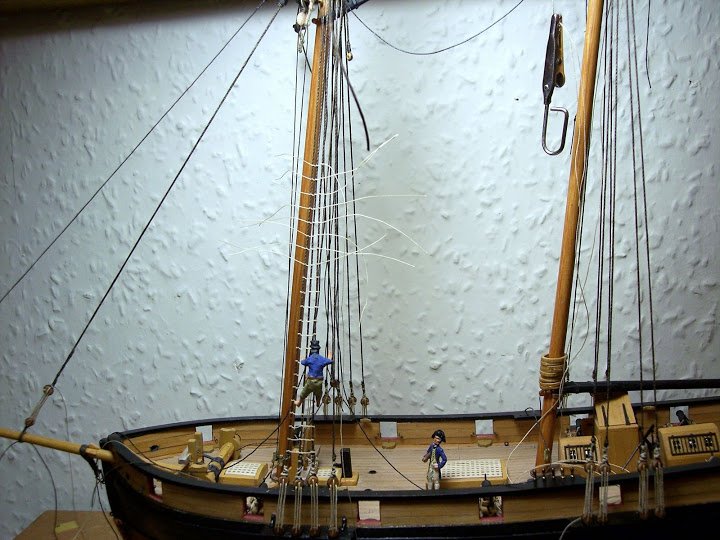
Many drawings both modern and contemporary of schooners show the ratlines across all lower ‘shrouds’ and I think it looks more balanced.
This view is supported by the builder of the Pickle model in the Royal Naval Museum, Rear Admiral C.M. Blackman, who shows the ratlines across all four ‘shrouds’ an arrangement that looks better and for my Pickle I’m going with it.
Only option then to remove the ratlines already fitted and start again. Fortunately I had sealed the end knots with diluted pva rather than ca so a little application of water and they all came away. Had I use ca I think we would have been in deep doo doo .
So after a false start the ratlines are complete, along with most of the standing rigging.
Amati 0.1mm dia line is used and on this build I have blackened the ratlines rather than leave them natural, this is in accord with the plans, but my decision is based purely on how they look.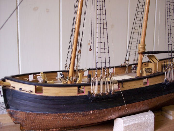
Spaced at 5mm (13” ) intervals it is not too onerous a job on a model like Pickle.
One small deviation in tying ratlines they should be done with a clove hitch but at this scale I have gone with a simple figure of eight, it produces a smaller knot that looks more in scale particularly as the top of the shroud is reached where the space is very tight. It is also much quicker to do fo8 knots.
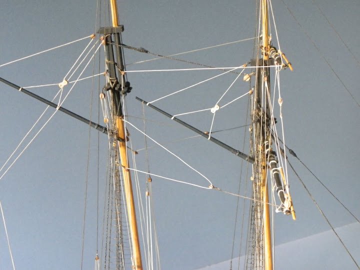
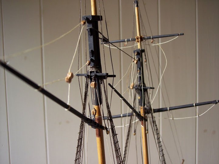
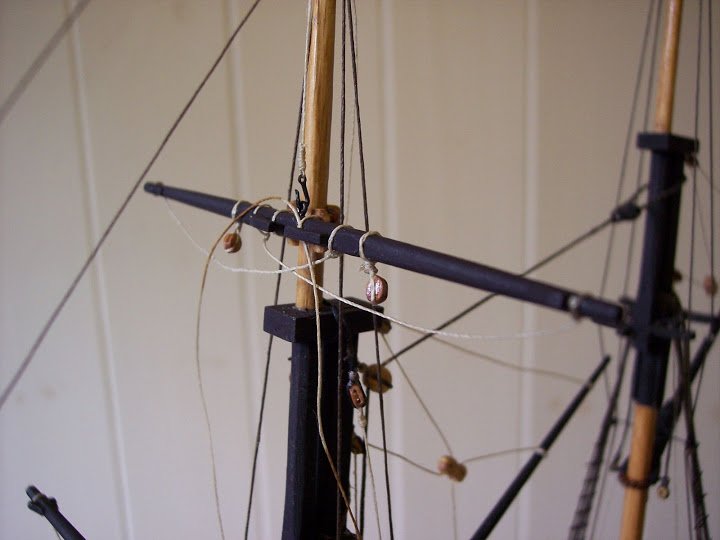
Getting very crowded around the Fore topmast head
Also fitted the Futtock staves which allows the completion of the Topmast shrouds. These run down inside the lower shrouds and belay to the channel deadeyes which would particularly have made the rattlin’ down more difficult if left until later in the build. A degree of foresight helps in rigging so you don’t by one action make things difficult for some later attachment.
Two blocks in a span are required to fit over the lower mast cap to take the cro’jack yard lifts. Best to fit them before the Topmast shrouds are fitted which would get in the way of the attachment.
They are quite tricky little beasts to do as the span has to be of the required length, falls of sufficient length have to be seized to the **** of the block, and the span has to fitted around the cap with a half hitch.
This is not work to try and do on the model, apart from the arm ache it will cause, stropping the blocks and doing the necessary six seizings in situ will be much more difficult.
Oh dear after all my work I found that the 3mm blocks would not pass between the masthead gap. Thankfully I had not glued the caps to the masthead and a little tap with a jewellers hammer released it.
The moral of this tale is that on any build if you can get away without gluing such things as caps, it may save a lot of aggravation down the road, but it does depend on the item having a snug fit.
Rigging the Gaffs
Some slight deviations from the kit instructions here.
The Fore Gaff (standing sling) and the Main Gaff (throat halyard)
Shot of the Main Gaff Throat halliard.
I made some changes to the suggested arrangement in terms of the sling set up and block and line sizes for the Main Gaff throat halyards. 3mm blocks and 0.1mm Ø line for the falls are indicated, but I have gone with 4mm blocks and 0.25mm line.
Belay of the Throat halyard.
Topmast Shrouds.
These are of 0.5mm dia line, stained, stretched, and waxed. They are eye spliced in pairs over the hounds and are fitted with a thimble tackle attached to the lower deadeyes, having passed inside the futtock staves of the lower mast shrouds.
Jotika suggest simply seizing them to the lower deadeye but I think a thimble tackle is more appropriate. 2.5mm boxwood thimbles were used.
Outer Jib or Topmast Stay and T’Gallant stay
Both of these are given as 0.25mm line, but ideally the T’gallant should be slightly thinner.
There is a slight difference between the Amati and Jotika 0.25mm line (the Jotika larger) I therefore used that for the outer jib and the Amati for the T’gallant.
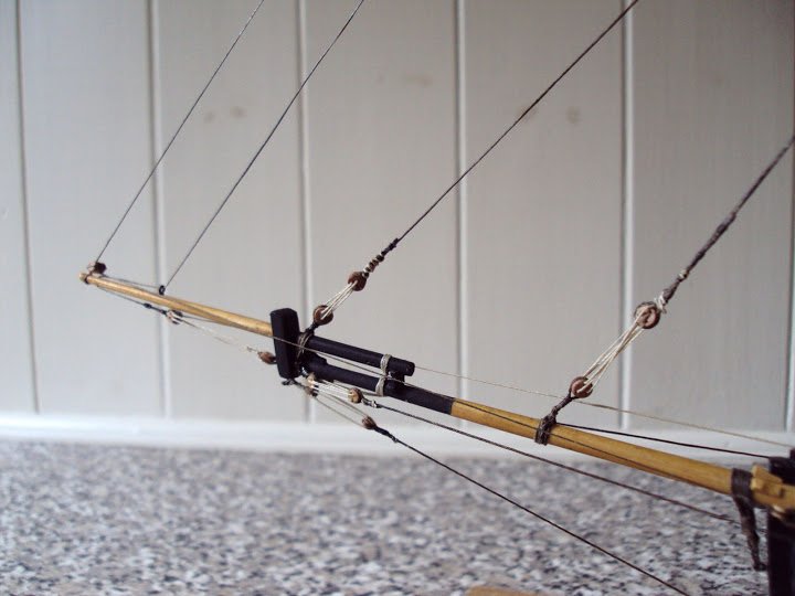
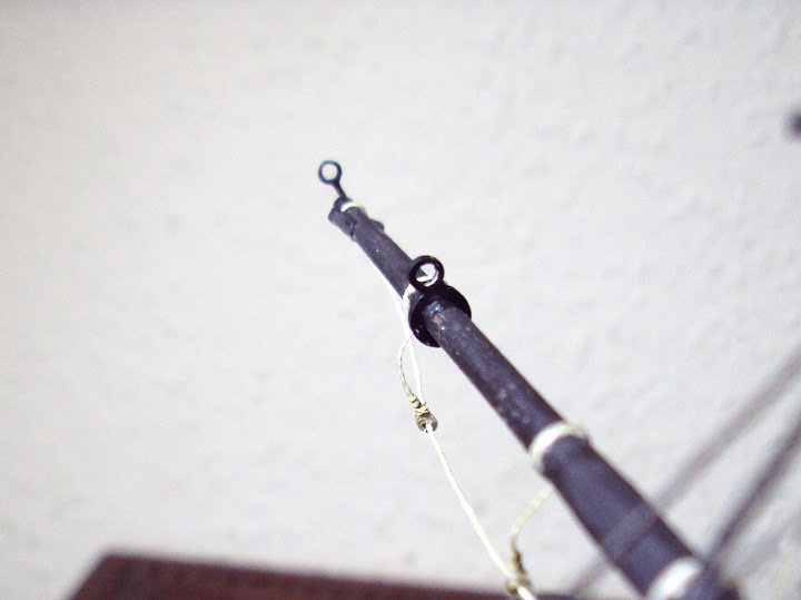
Rigging of the Bowsprit/Jibboom completed, apart from horses, not included in the plan, but I think would have been rigged.
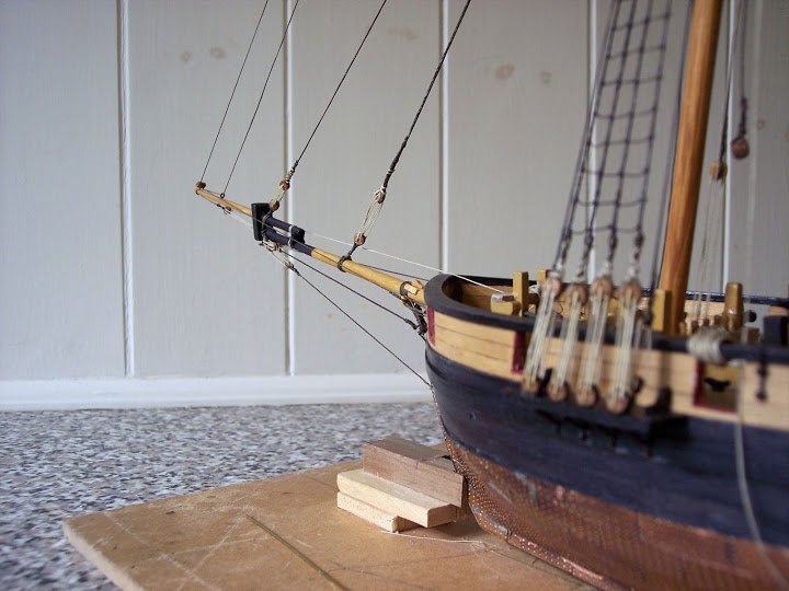
The Tgallant stay is supposed to pass thro’ a 3mm single block at the Jibboom stop, but this was replaced by triple 3mm block to allow for the Topsail bowlines (not included in the Jotika plan.)
The Topsail yard is now fitted, the trickiest part being attaching the parrel.
For the halyard I have used a eye and hook arrangement rather than tie the sling
Jotika suggest only one row of parrel ribs and rollers are fitted, but I feel a double row is more appropriate. I also didn’t like the provided brass etched ribs, or for that matter the black and shiny rollers.I replaced them with boxwood ribs and seed bead rollers. I also diverted from the plan by adding footropes to the yard.
I am toying at the moment as to whether to fit studding booms to the yards, and until I finally decide I cannot tie off the parrels.
B.E.
-
A minor blip in proceedings
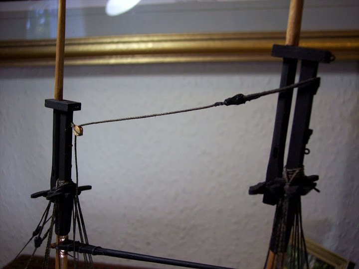
On Schooners the Main stay (sometimes called a jumper-stay.) was rigged very differently to other vessels because of the need not to interfere with the Fore gaff sail. For this reason it was taken from the Main Mast head thro’ a block on the aft side of the Foremast, had a double block turned in the end, with a tackle hooked to a ring bolt on the deck aft of the Foremast.
Following the Jotika plans a 1mm Ø line was required as with the Forestay,
Sooo.... the line was prepared, stretched, dyed , waxed, served, and moused, only to look far too heavy when fitted.
Oh dear I thinks to myself that surely can’t be right, so a ferret thro’ my reference works is required.
I find that:
Under this arrangement the Fore stay carried most of the load for both masts and had a stronger stay than that of the Main stay which was of a similar diameter to the lower shrouds.
So much for:-
The Rigging plans have been drawn following extensive research, contemporary and modern. We would recommend that you follow these drawings exactly unless you are converting the model to an earlier or later version of the ship. (Whatever that means)Nothing for it but to start again, this time using 0.75mmØ line
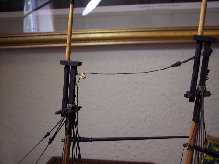
Doesn’t look much different on the photos perhaps but in reality there is a marked difference in the look of the line. Note also the 5mm lead block at the Foremast head, this is the much improved JB pear wood version.
Moral of the tale – check every line size against reliable sources before going ahead.
Still could be worse I could be relying on AL rigging plans

Rigging the Fore gaff – a juddering halt
This is a confusing area in schooner rigging both in arrangements and terminology.
Fore and aft schooners sometimes carried a sail equivalent to the Fore course on a square rigger, and this yard called a crossjack yard, was raised and lowered on the foremast. With this arrangement the gaff for practical purposes was above the yard.
The gaffs could either be slung ( held in place with a sling) in which case they did not travel up and down the yard; or could be hoisted up and down the mast, in which case a throat halliard was employed.
This was often the case where the gaff was associated with a boom (as on the Main mast) obviously in this case the gaff would have to be below the square yard.
Topsail schooners which carried a square topsail had a crossjack yard or perhaps more properly a spreader yard to carry the clew of the topsail.
When I came to do this the plans call for the gaff to be slung above the Crossjack yard on the Foremast.
This puzzled me somewhat as the plans and references I have seen for Topsail schooners show the gaff below the yard. The more I thought about it the more it niggled me.It didn’t seem logical that the gaff would be above the square yard even if fixed, so the rigging came to grinding halt. I had to reconcile this before I could move on.
The more I read the more the doubts increased.
Pictures by Geoff Hunt, Gordon Frickers, the model in the Naval museum, the replica Pickle all showed the gaff below the square yard, but of course these aren’t contemporary references.
More in hope than expectation I phoned Jotika and spoke to Richard, designer of the kit, a very helpful guy whose obviously very interested in his subject.
It seems he has gone with contemporary sources, notably a painting by Robert Dodd, an artist of the time, and a book entitled News of Nelson by Derek Allen and Peter Hore.
I have this little book and very interesting it is too.
So on the one hand there is a contemporary painting, and on the other many published works and other references that show the gaff below the yard.
No doubt all these worthies took time and trouble to research their subject, and no doubt had access to information and historians that I do not
The more I looked at the spread yard / fore gaff relationship the odder it looked to me.
The Jotika plans for the spread yard indicate its position some 45mm below the Trestletrees; this would result in an enormous roach to the topsail to avoid excessive rubbing of the Fore and jib stays, far more than would appear on the Dodd painting.
There are no plans of Pickle, there is no real evidence what she actually looked like, even her origin is open to debate, she was after all a small work horse vessel and would not have gained fame were it not for the Trafalgar dispatches.
The arrangement in the Dodd painting may or may not be correct, but work by other contemporary artists show the gaff below the yard.
I scoured every book in my collection for contemporary art work that supports the Dodd image but could find none. Except that is in relation to Fore and aft schooners where a square sail was set on a crossjack yard.
In the meantime I received an e-mail reply from Richard Wright the Technical Manager at Jotika.
I repeat it here for any future Pickle builders for whom the same conundrum may arise.
3 September 2010
I apologise for the delay in getting this over to you but please see the attached image, an enlarged section of the painting by Robert Dodd titled “Victory of Trafalgar in the Rear”, showing the Schooner Pickle. This was our primary reference for depicting Pickle with the gaff above the crossjack.
I have also pulled out some of my old notes and found specific reference to this point which, in brief, is as follows:Fore Gaff above or below Crossjack?
Evidence of both methods on various plans of Schooners from the period – majority appear to be below.
Unable to find specific documentation to detail preference of one method over the other – appears that positioning the crossjack below the gaff allows a larger spread of sail?
Use reference of Robert Dodd image, gaff above crossjack, as most likely orientation for Pickle.I should also point out that my notes deal with the omission, from the kit, of the topgallant (or royal) yard on the fore mast as well as the topsail gaff on the mizzen mast (shown in the painting) – on a schooner the size of Pickle these would rarely have been shipped and only then in conditions of very light breezes. I am of the opinion that Lapenotiere has had Robert Dodd show them on Pickle in order to have his own schooner appear a little more grand than she might without them.
Please note that the attached pdf was originally emailed to me during my correspondence with Peter Hore and I am providing it here for your own reference only. Copyright for the image is owned by the author/publisher.
Kind regards
Richard Wright
Technical ManagerIt was very good of Richard to take the time to respond to my query, and shows perhaps the commitment of Jotika to their customers. This is a big plus in my opinion.
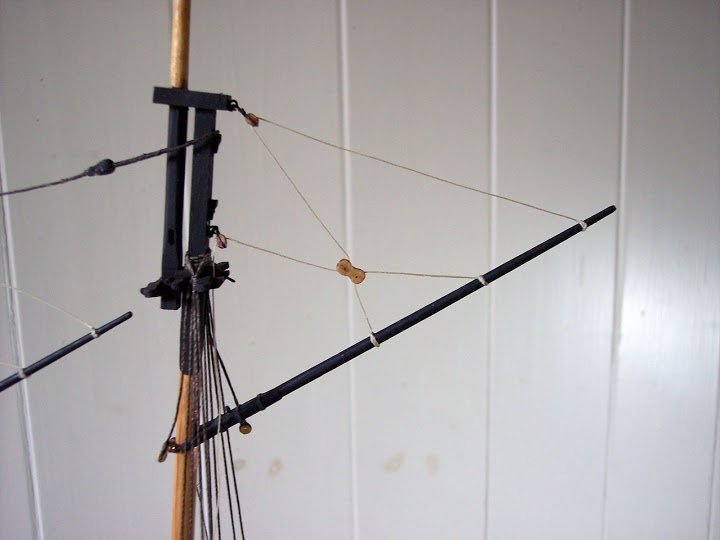
However, after more deliberation the huge gore requirement in the Topsail clinched it and I decided I couldn’t live with the given plan so the Fore Gaff sling was cut and the gaff was moved down the mast to allow room for the spread yard.
To finish off the gaff the spread yard now had to be fitted so that the truss could be put into place before the gaff sling was re-rigged. This wouldn’t have mattered with the yard in the lower position.
The gaff can then be finished off with the seizing of the standing sling and rigging of the Topping lifts.
Topping Lifts took various forms but after some research I decided to go with the particular line arrangement indicated in the plans, and on the Dodd painting as far as I can see. I wasn’t however impressed by the Jotika method of making a ‘sister’ block from a supplied 5mm common.
Topping lift set up
Until the Vangs are put into place the correct degree of tension cannot be applied to the Topping lifts.
What Jotika refer to as a ‘sister’ block is more properly a Leg and fall block, which I fashioned from a 7mm boxwood single, the extra size gave more scope to get the correct profile.
Leg and fall block on Main Gaff.
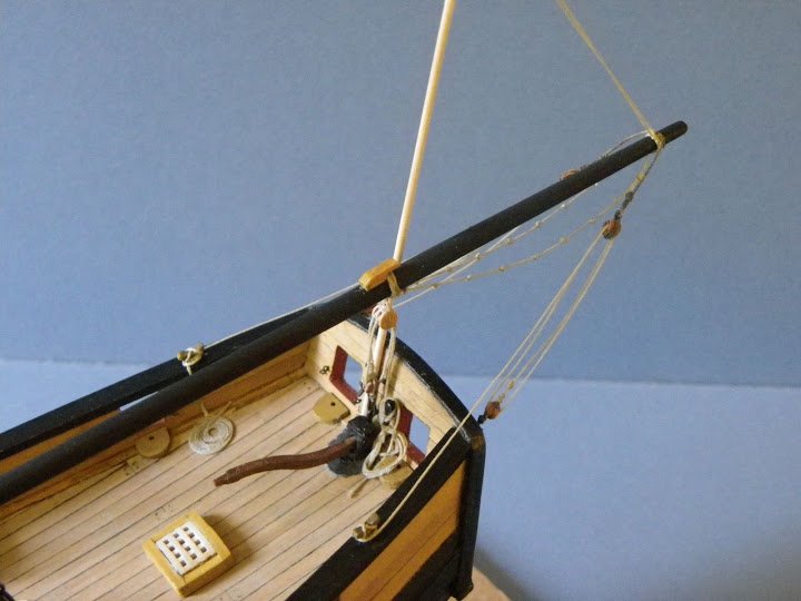
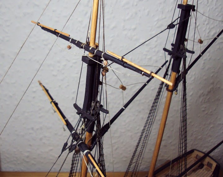
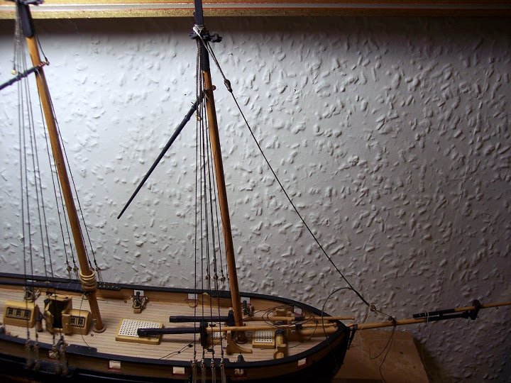
So here we have the revised arrangement , the spread yard will swing somewhat free until fully rigged; one of my foibles is to glue as little as possible on models and I really don’t like pinning yards to masts if I can avoid it.
A comparison with the kit arrangement can be seen in these photos.
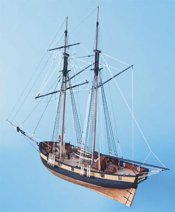
Kit plan set up.
This is the familiar set up of topsail schooners
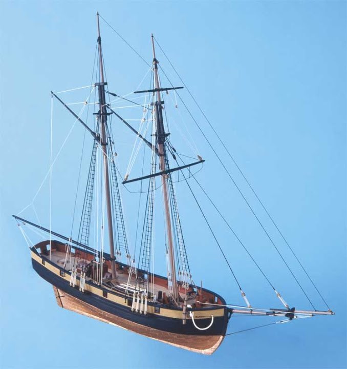
With the yard in this position is can be seen what a large gore would be required in the topsail to clear the stays.
The yard could be moved up some I suppose, but not in my case where I have fitted cheeks below the Trestletrees.
B.E.
-
Anyone got a good Mouser

No not you Tommy..
Tommy was a good mouser, but not the sort I’m after.
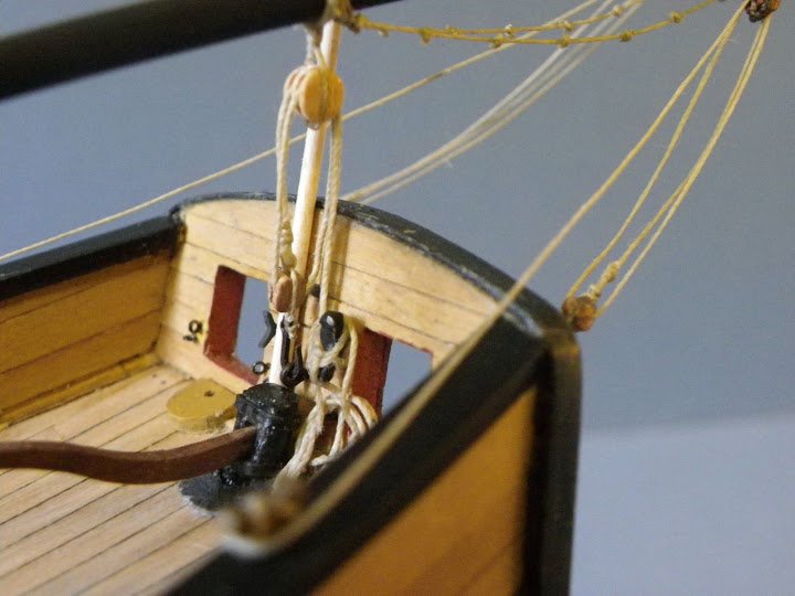
Before I can do the Forestay a mouse has to be made.
Mouses are easy enough to make, it’s the finish that matters.
In reality they were ‘raised’ on the stay itself and have a distinctive woven appearance, this is the tricky bit to replicate, particularly at small scale, and even at 1:64 the Pickle Mouse is still only 6x3mm.
I have made my mouses using styrene tubing shaped on a length of 1mm brass wire.
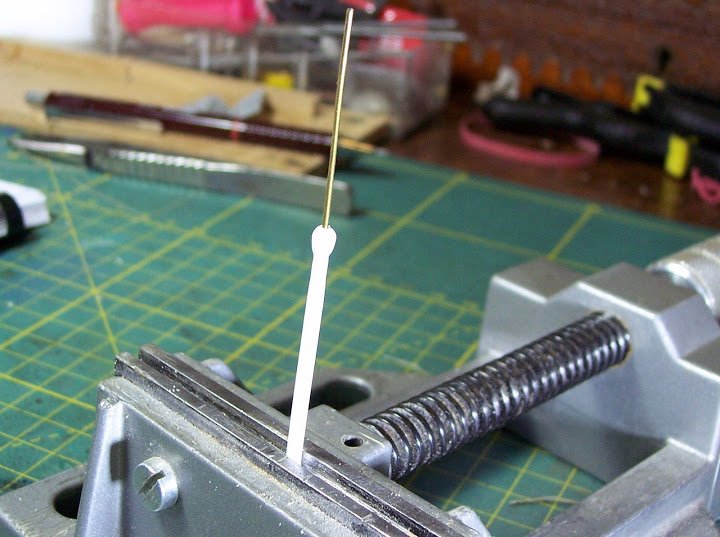
So far so good.
But how to replicate that woven look in a scale pattern.
A rummage thro’ Mrs W’s tights (panti hose to our American cousins) drawer, to find a pair past their best. This is the most dangerous part of the build so far.

I would have asked but she’s gone to the Golf Club, and well needs must....
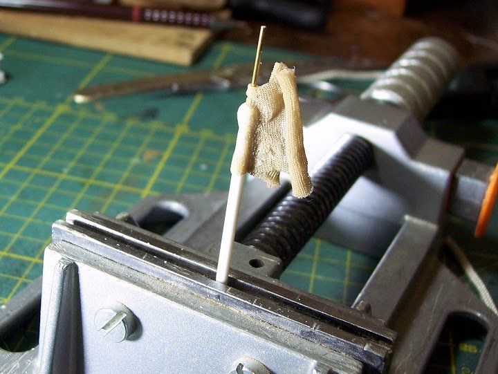
A piece of the material is stretched around the mouse which has been coated in ca, when dry it is trimmed and painted.
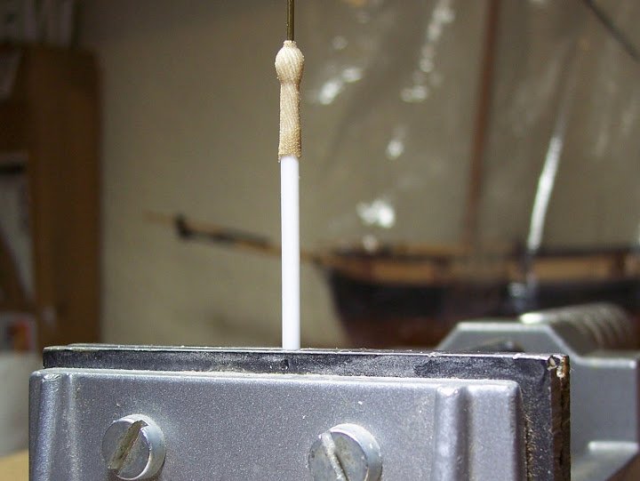
The completed article.
The Forestay collar is served from the eye to the mouse, for this I used super fine silk thread.
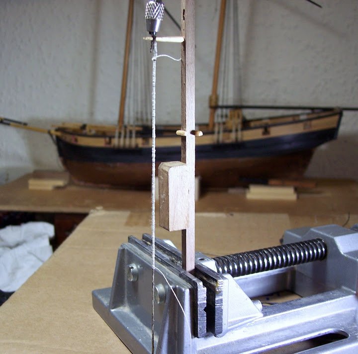
This was done by hand but if I had to do much of it I think a small serving device would need to be cobbled together.
The served collar before staining and on completion with the mouse fitted.
I will not seize off the lanyard until later in the build, minor adjustments may be required when the other tackle is installed.
I include this pic to show the effect of stretching and waxing the stay. It hangs loose in a natural curve without any tendency to kink.
The completed stay with deadeyes and lanyard fitted, the same procedure will be followed for the other fore and aft stays.
B.E.
-
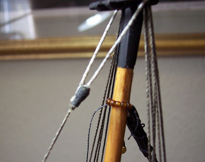
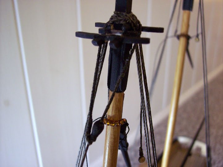
Standing Rigging – Mast Pendants and shrouds.
The first item over the mast head are the Mast Pendants, of the same size line as the shrouds.
Jotika suggest that a 3mm block is seized into the ends of the pendants but I prefer to fit a thimble into which a tackle may be hooked. (Both arrangements are acceptable)
Having seized the first pendant the second thimble is inserted at the correct length before seizing.
One of the reasons why I tend not to glue the mastheads in place at the outset is so that the pendants and shrouds can be made off the model and then be slipped over the masthead for final settling.
It is less tiring and easier to do the seizing than if the shrouds were fitted insitu. A piece of square section stuff is used as a former around which the shrouds are made.
A cobbled together jig for setting up the shroud seizings.
As with the blocks I have opted to use JB Pearwood 4mm deadeyes, these were lightly stained in mellow pine to darken them a little.
Here a piece of bent wire is used to gauge the distance between the deadeyes.
The shrouds are of 0.75mm line and the lanyards 0.25mm. Seizings were of 0.1mm line. The seizings once secured were painted with diluted pva to secure the knots.
The beauty of pva is that once dried it does not show unlike ca which dries shiny.Once fitted the lanyards are tightened progressively and the excess fed thro’ the shroud bight, back around the shroud, under itself, pulled taut, and then wound around the shroud above the deadeye before being seized.
This is not a particularly tidy arrangement as can be seen on Victory, something I have tried to replicate on Pickle. (well that’s my excuse anyway)
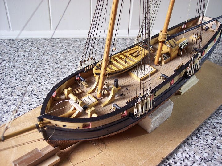
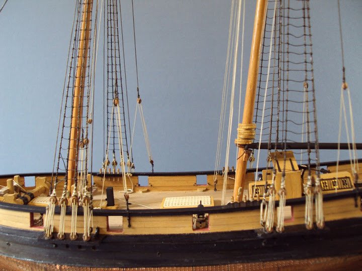
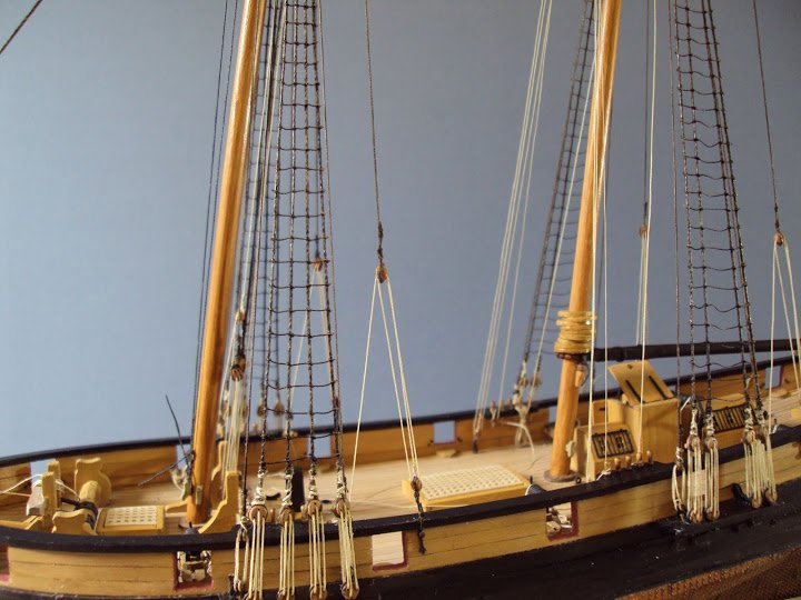
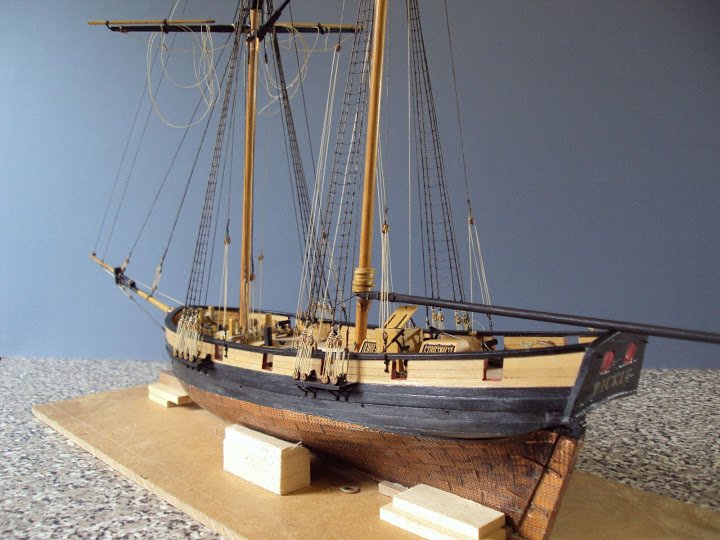
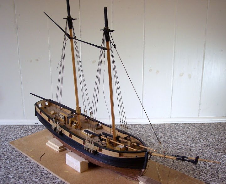
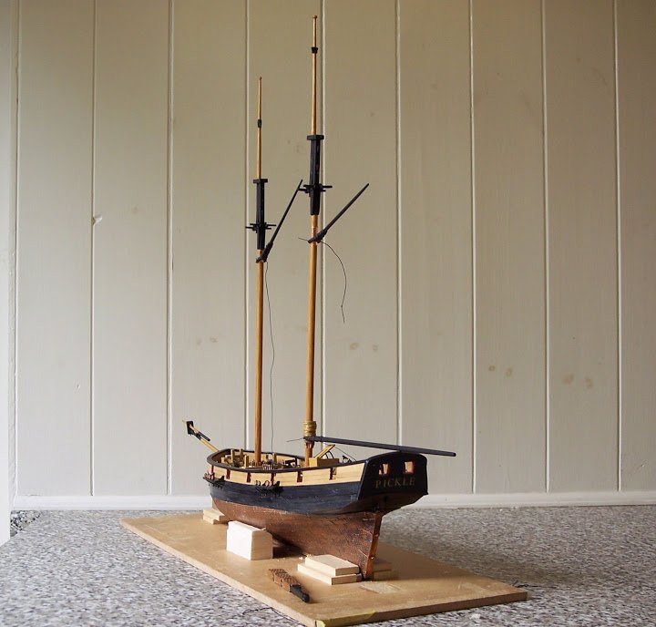
Starting to look quite schoonerish I think.
Compared to shrouding a big square rigger with its 28 pairs, fitting eight pairs on a fore and aft schooner is something of a doddle.
Before I go .... .........pan outwards - this is the reality of the chaos I actually work in.
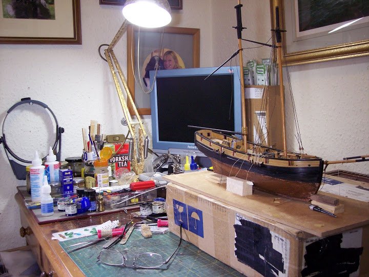
Moving swiftly onto the stays I think.
B.E.
-
The Yards
Fortunately there are only two of these to make, both from dowel with the ends tapered. (Jotika)
The centre section of yards on British vessels were generally octagonal in shape so rather than use the provided dowel, I turned the yards from square section walnut strip, forming the octagonal first and then rounding the arms on the lathe.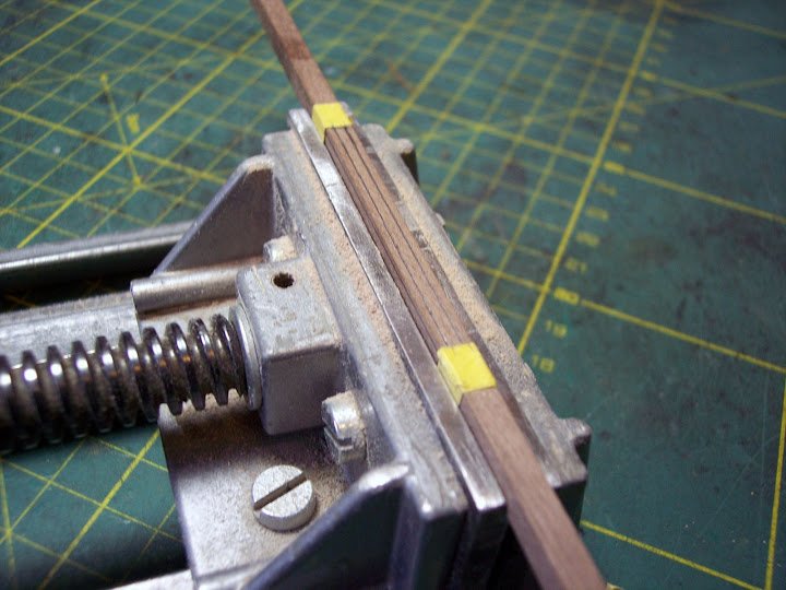
There are only short octagonal centre sections for the yards so having marked the lines in pencil, I used flat needle files to form the octagon, not even enough room for my miniature bull nose.
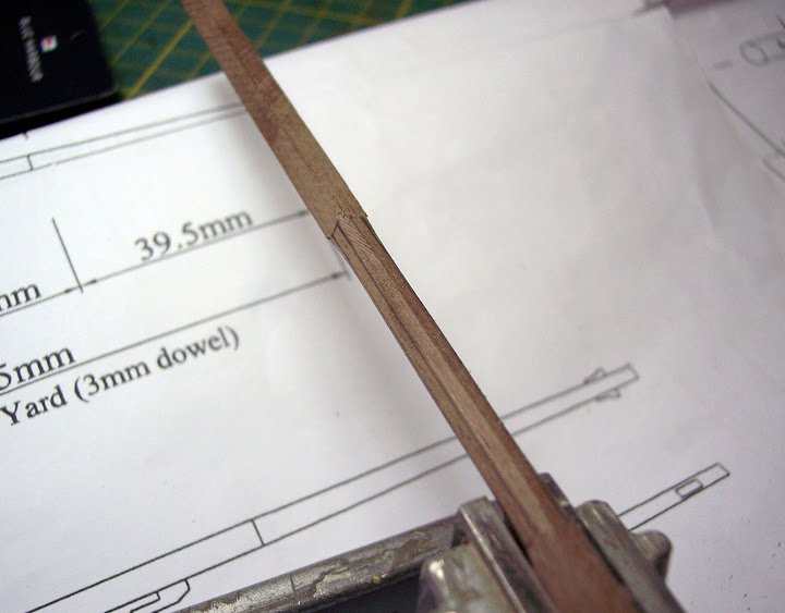
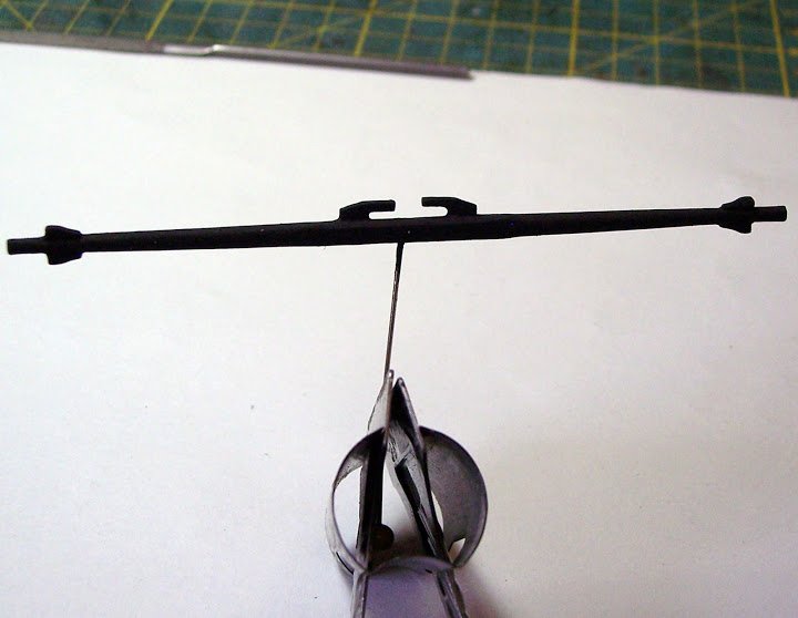
The completed Topsail yard fitted with sling cleats and stop cleats.
Rigging the yards.
Footropes are shown fitted to the lower (Spread) yard, but none on the Topsail yard.
Jotika suggest using brass wire for the stirrups, fixed into holes drilled in the underside of the yard, and having eyes formed in the end to carry the horses.
This is a method I have used on small scales, but at 1:64 a more realistic representation can be made.
The stirrups should hang down the back of a yard with sufficient line to be wrapped three times around the yard and then nailed. Each stirrup having a thimble turned into the end thro’ which the footropes can pass.
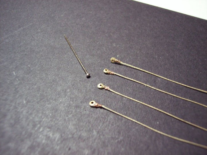
The thimbles, of necessity very small, were cut from 0.9mm brass micro tubing in 0.75mm slices. The stirrup was seized around the thimble and secured with a spot of ca.
Fortunately there are only four to make.
They should hang around 36” below the yard - 14mm at scale - but see below:-
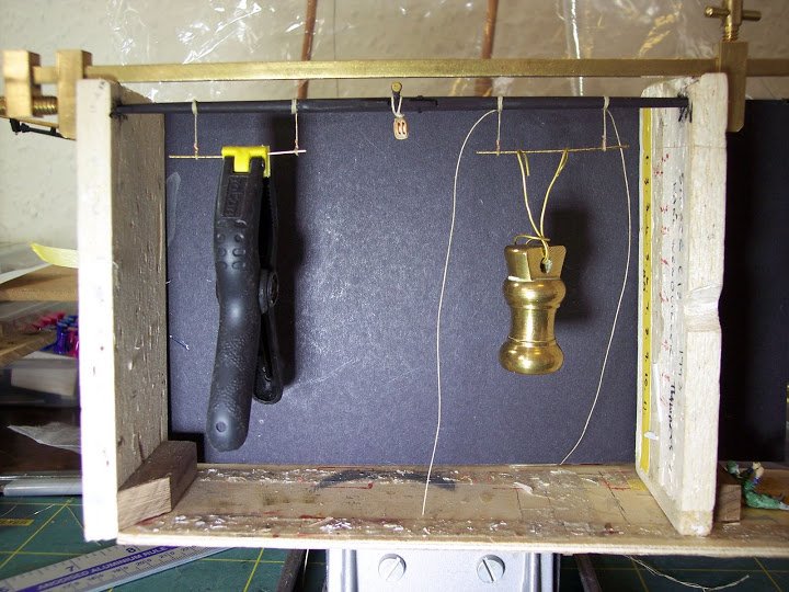
I brought my Heath Robinson patent yard dressing jig into use to fit the stirrups.
Once fitted the stirrup is painted with dilute pva to stiffen it up, and weights are attached until dry.
The Footropes(Horses) can then be threaded thro' and each seized on opposite sides of the slings.
Also attached are the thimbles for the yard sling and truss pendant, and a 5mm block to take the Topsail sheets. This is one of the JB blocks, much improved over the boxy kit ones, having the correct shape and including sheaves.
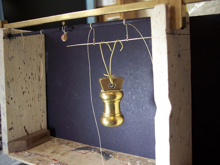
Given the size of the yard the footropes looked to hang too low given Jotika’s suggested 15mm, even tho’ that equates to only 36” if it don’t look right it won’t do.
I had to conjure up a 1:64 scale top-man to verify the accuracy.Tom is a scale 5’6” tall, and the footropes actually hang 12mm below the yard, a scale 30”.
They are I think low enough, but with a 15mm drop poor Tom would be hard pressed to have a foothold when leaning over the yard to gather in the sail.The yards will be put aside now until the shrouds are fitted, the next major operation.
B.E.
-
A small diversion – prepping the rigging line
It won’t be too long before I need the first items of standing rigging, pendants, shrouds and stays.
I have written about my method of preparing rigging line in relation to my other builds, but for completeness of this build log I summarise it again here.
The suggested line sizes were checked against other sources, and generally Jotika seem to have it right.
I don’t intend to use the Jotika provided thread, the running rigging line is too pale for my taste, and I don’t like commercial black line for the standing rigging.
My favourite commercial line by Amati will be used.
I prefer to dye my own standing rigging using Dark oak wood stain, following which the line is bees-waxed and then stretched on a rack for several days or in the case of the stays hung by weights.
This has the advantage of making the setting up of the rigging easier, there is less tendency to pull the rigging too tight, and gentle curves fall naturally when required to give an impression of weight.
In my builds I prefer a combination of taut and slack lines which I think add realism to the rigging.
Whilst I am waiting for the lines to ‘mature’ there are the masts to step and the yards to rig.
I must now also decide the sequence of rigging.
Reading the Jotika blurb, fixing the Gaffs and boom comes some way after rigging the shrouds /stays etc.
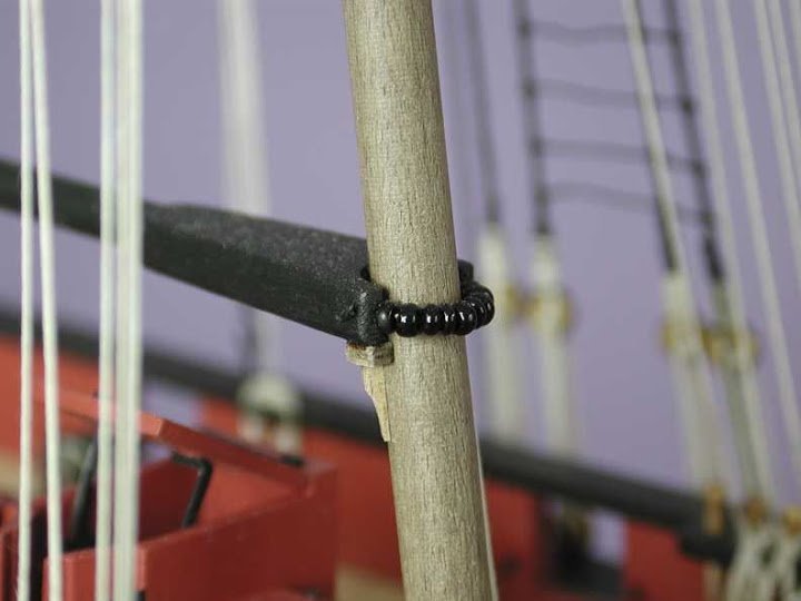
To me this would serve to make attaching these spars to the mast more difficult in the sense of fixing the parrel beads around the masts, so I decided to fix them as the first items of main rigging, but leaving sufficient line for any later adjustment. It is far easier to attach the parrels to the gaff jaws first and then feed them over the mastheads into position.
I discarded the black and shiny kit supplied beads in favour of other seed beads I have, they will be coated in flat varnish to take the shine off them.
Jotika also suggest that the booms and yards be pinned into position, I prefer to have them free running and use the rigging lines to hold them in position, although with pinned spars setting up the lines is easier in the sense of having something fixed to pull against.
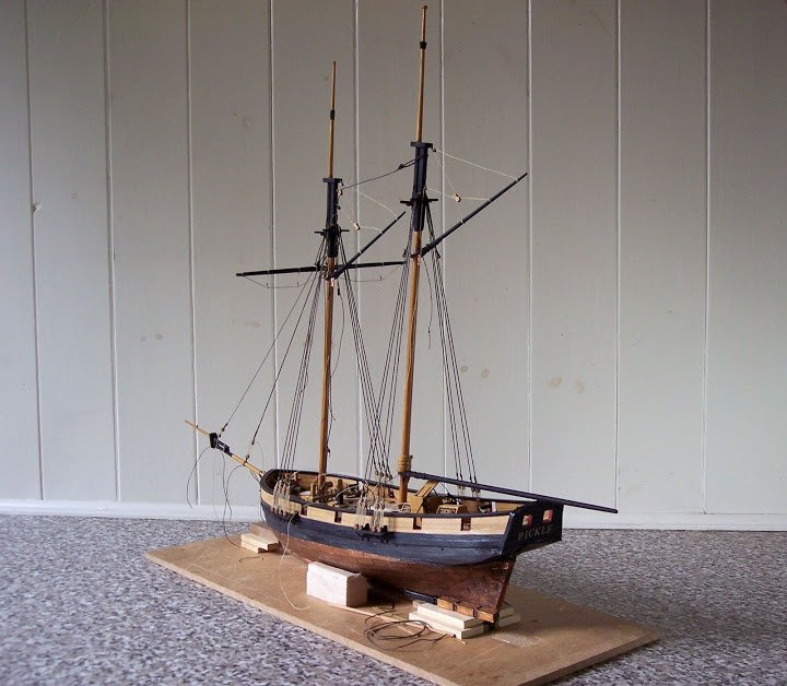
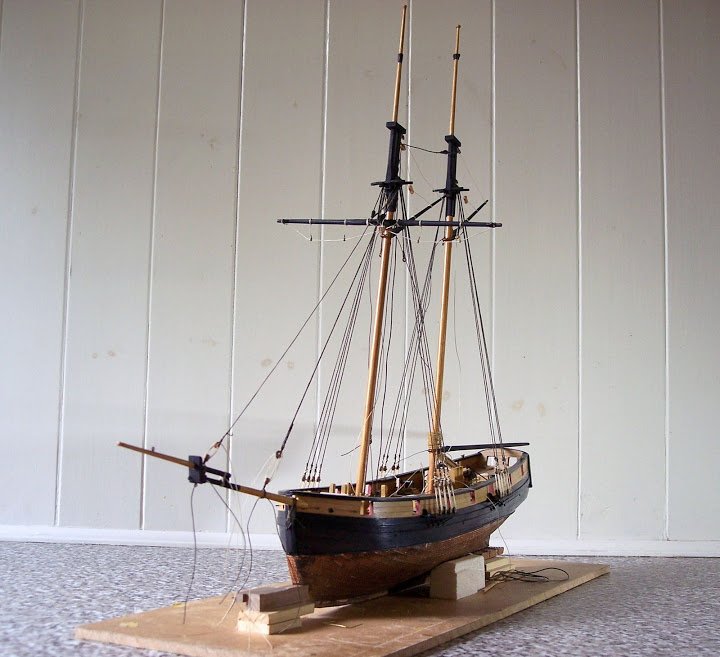
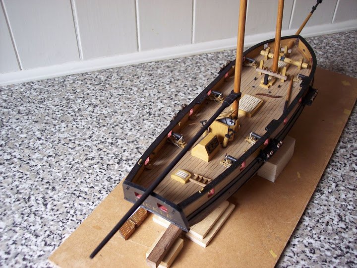
Well the masts are stepped;
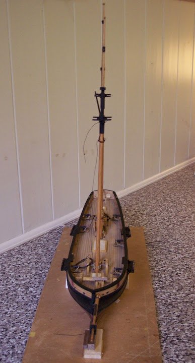
Hopefully in line.
The bowsprit fixed, the gammoning applied.
and the booms in place.
Back to the yards, but these will be fitted once the standing rigging is in place.
- Mirabell61 and Mr Whippy
-
2
-
Work on the masts has now largely been completed.
Top rope Sheaves are drilled.
Mainmast head assembled.
Foremast head and hounds.
The Gaffs were also completed in the same manner as the Driver Boom.
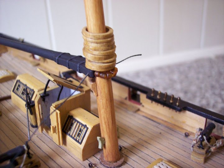
MAST HOOPS
This is something not included by Jotika, but applicable to the Main Mast.
These wooden rings were used where a driver boom was used in conjunction with the Gaff to provide ease of movement up the mast.
I had to remove the boom saddle in order to get them over the mast.
There are nine in total, made with a strip cut from a brown envelope and rolled around a piece of dowel several times, coating the paper with diluted PVA as I went along, and then finished with shellac in the guise of Knotting.
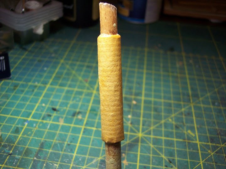
The dowel was sprayed with silicone polish to deter adhesion from the white glue.
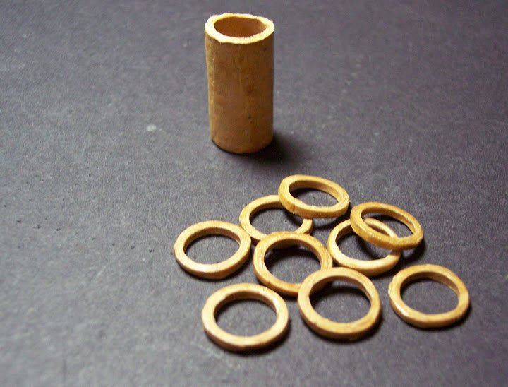
The hoops are then cut from the now stiffened paper tube using a scalpel.
Further coated with knotting, they are then sanded to the required thickness
According to Marquardt the internal diameter of the rings should be 11/2” – 2” larger than the diameter of the mast which in the case of Pickle meant a 7.5mm dia rod as a former.
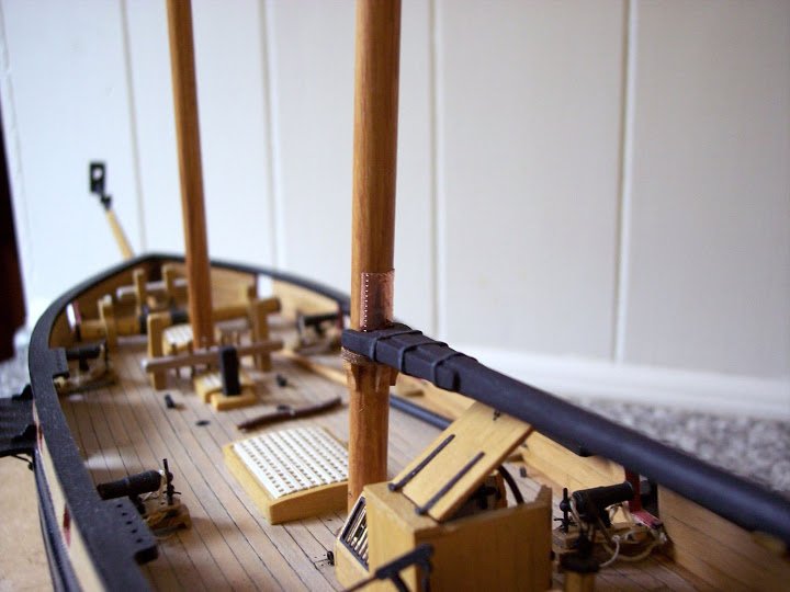
One other feature is required around the area of the gaff and Driver jaws, that is copper sheathing to protect the masts.
Copper tape impressed with a riveter was used for this.
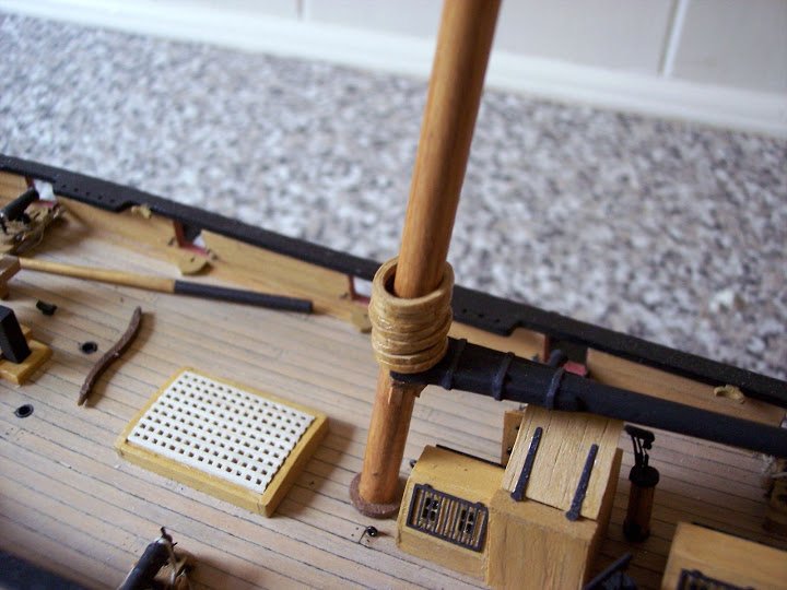
The Mast hoops sit atop the Driver jaws.
Just the yards to finish off and it’s onto final assembly.
B.E.
-
Cheers Mike, it was my first attempt at coppering, and Pickle ain't a bad kit to start it on, not too much of it.
I think we have seen logs we wished we had seen before we did something, I know I have.
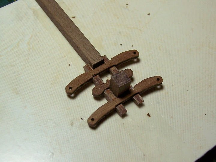
Gaffs and Booms
One of the things I noticed quite early on when perusing the kit parts was the horrid lumpy clumpy Gaff and Driver boom jaws.
I suppose I shouldn’t get onto Jotika too much as this is an entry level kit, and I understand that they perhaps don’t want to present the modeller with too much shaping of parts, but they do state that;
Pickle is an exact scale model designed using original Admiralty plans (what of Pickle?) All fittings, masts and rigging have been researched using contemporary sources and the most up to date reference material available.Although Jotika indicate tapering of the booms the said jaws are to be simply joined to the inner end using a piece of brass wire.
For me this simply will not do.
Unfortunately the provided lengths of dowel are too short to other than follow the intended method, so an additional length of dowel had to be found.
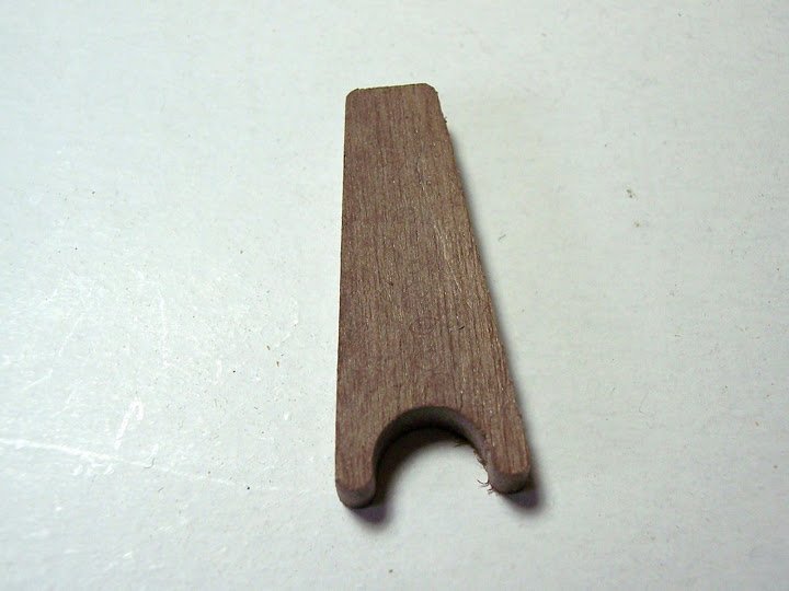
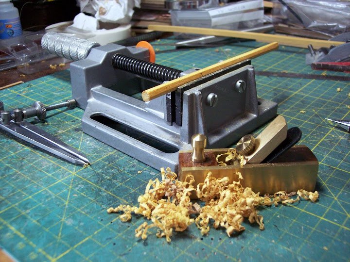
After turning the boom to the correct taper, the first job to add a little more realism is to put a flat taper on the inboard end to take the jaws.
For this job the little Silverline miniature planes come in very handy, but I must admit it is the very devil to keep an edge on the blades, and I seem to spend as much time with the oilstone as I do planing.
Once satisfied with the taper the angles can be drawn onto the provided walnut lump. (the jaws) which can then be split into two sections, but before that is done the piece requires reducing in thickness by around 1.5mm.
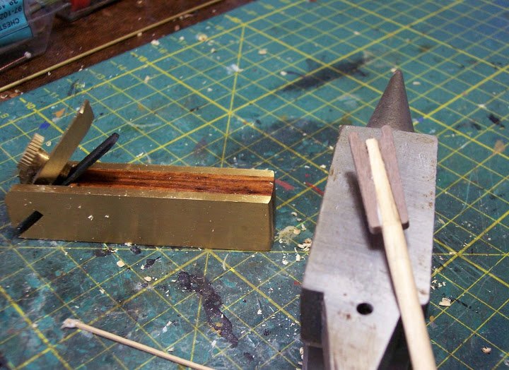
Here the pared down and split jaws have been attached to the boom ready for final shaping, at this stage they don’t look much better than the lumpy clumpy whole piece.
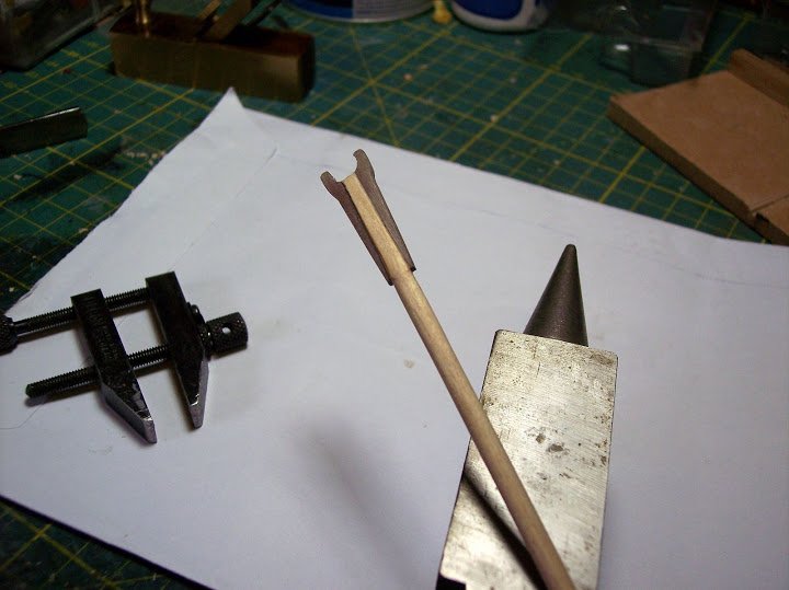
Finally shaped and a dry fit on Pickle,
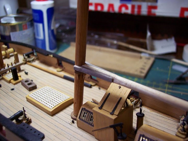
The iron bands have been fitted.
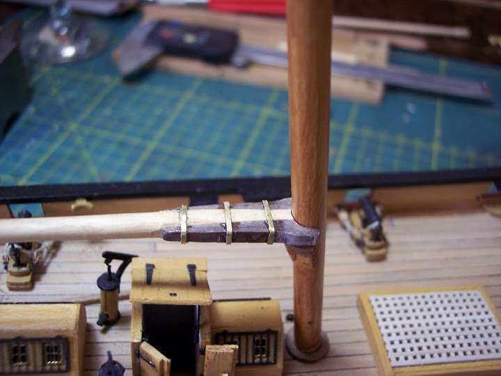
The waste brass etch framing comes in very useful for ‘iron’ bands
And finally the completed Driver Boom.
I think this fairly straightforward modification greatly improves the look of the model over the Jotika simplified arrangement....
The boom jaws as kit supplied.
A similar conversion will be made on the Fore and Main Gaffs, which if anything look even worse without modification as the booms are much finer in relation to the jaws.
B.E.
-
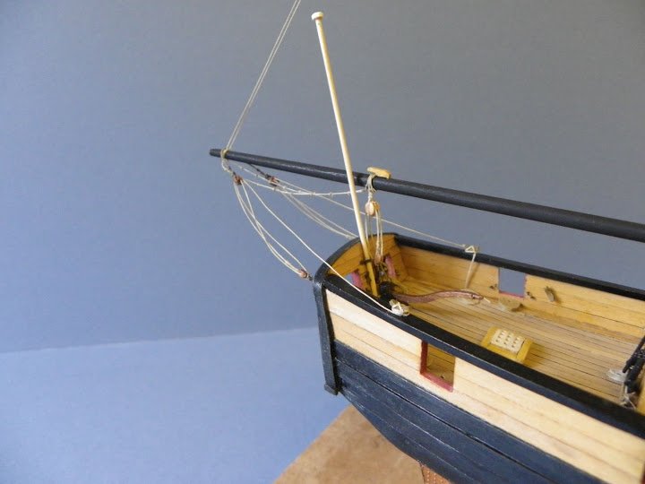
Masting and Rigging – the final stage
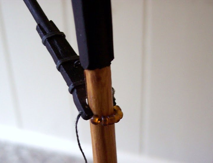
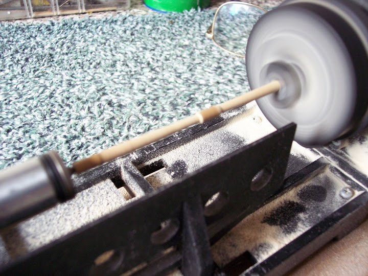
Various sizes of Birch dowel are supplied to make the masts, the mast fittings are cnc walnut shaped parts which need some fettlin’ to get them to scale.
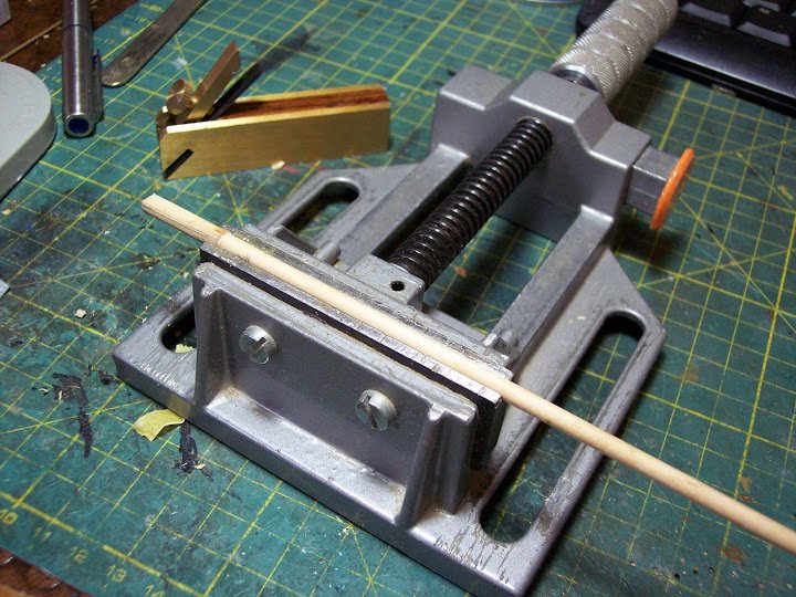
First up are the Bowsprit and Jib, for which my somewhat temperamental Mantua spar lathe with its very erratic toggle switch, is brought into use.
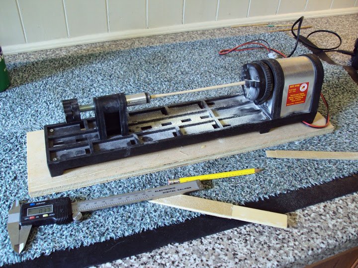
To taper the spars I just used sanding sticks with a range of grit papers glued to them rather than cut the taper in with a blade. With this size of stuff it is less risky than the blade.
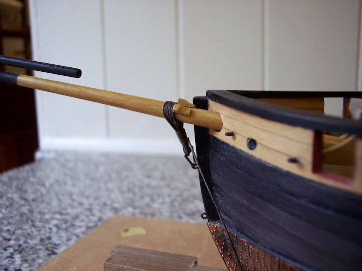
In fixing the bowsprit and jib there are several things that have to be considered at the same time, the bowsprit has to sit squarely between the standards of the Pawl bitts, and has to run parallel with the stem and with the right degree of stive.
The angle of the mast cap has to be determined, so that it is vertical to the waterline, and the jibboom which passes thro’ it, sits parallel to the bowsprit.
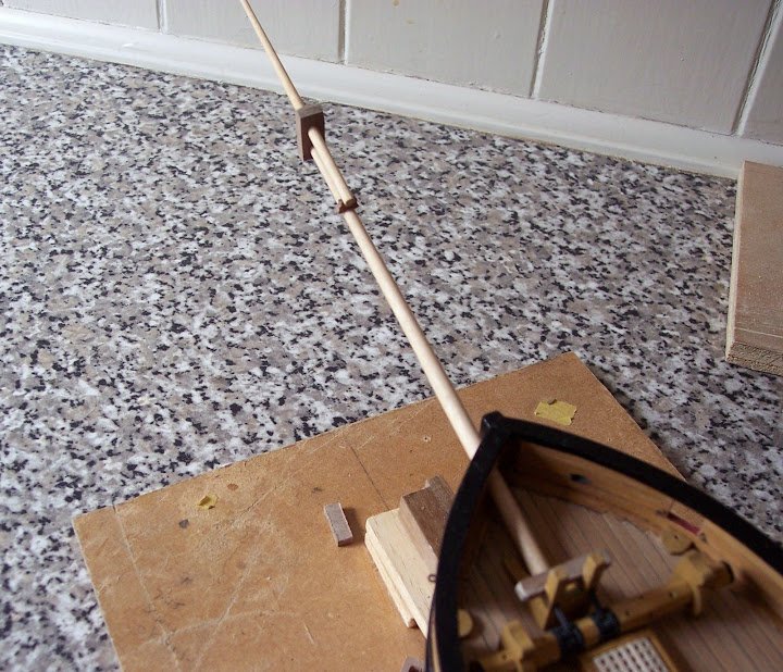
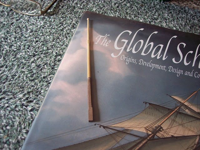
The Bowsprit cap was a tricky little beggar to make, I scrapped three before success.
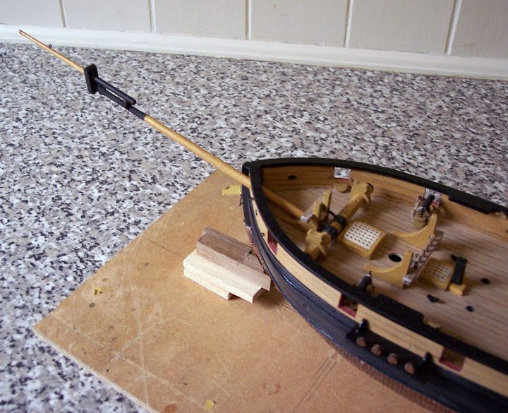
Jotika provided two cnc walnut caps(one spare) into which angled holes for the bowsprit tenon and the jibboom had to be drilled.
Problem is that no matter how carefully I drilled the holes the wood split away from the walnut faces. It was not until I drilled the holes in a piece of scrap and then cut the profile that I got the result.
Initially I thought that the cap looked a liitle bulky but when I checked the scale dimensions against the jibboom diameter it was spot on.
I modified the cap by cutting a groove on the aft side to take the jack staff, and drilled holes in the jibboom for the heel lashing and a sheave for the outhauler. I also formed a necking at the jibboom end, something omitted by Jotika.
I also needed to decide at this stage how to colour the masts, Jotika suggest staining them walnut, rather unappealing in my view, I will not be staining them walnut.
A little bit of trialling with various mediums, and I finally settled on a light oak satin varnish, enhanced with a touch of natural wood finish.
Now onto the mast assemblies.
Fore (or schooner Mast) and Main Masts
Jotika have these at 6mm diameter for their full length to the head which is formed by a separate square section of 4x4mm. The head section and mast have to be drilled and joined by a piece of brass wire and Jotika provide a centre finding template for the round section dowel, to assist the process.
This simplification (also used by Longridge in his Victory build) saves the modeller the task of squaring the mast head, but does not allow for those who may wish to do so, as the provided dowel lengths are too short.
The straight 6mm dowel just doesn’t look right to my eye, using Steel’s Fraction tables for masts I calculate that there should be a taper from 6mm at the partners to 5mm to the start of the head.
With the Jotika method the top of the round section outside of the masthead has to be angled so that the cross trees when fitted run parallel to the waterline, not to the rake of the masts.
The Trestletree/crosstree parts are cnc cut walnut, ok, but some adjustment was required to fit around the mast head. Double sided tape and a piece of the masthead timber were needed to set the piece out before gluing.
At this point I departed from the Jotika build instructions, as I fitted cheeks to the masts, the top angle of which created the parallel line for the Trestletrees.
A simple enough modification, and a feature that my research tells me was appropriate to schooner masts as well as larger vessels.
Main Topmast
This again is constructed from two sections, the lower section being fashioned from 4mm walnut square section, shaped to an octagon above the topmast sheaves.
As with the lower mast, it is connected by brass rod to tapered dowel for the upper part of the mast.
Jotika didn’t suggest it but at 1:64 scale I think a topmast sheave would be appropriate, so one will be cut into the heel of the topmasts above the fid.
Fore topmast
This differed from the Main Topmast in that it is supposed to be constructed from three sections, the first square stock shaped to an octagon, the second up to and incorporating the hounds (not present on the MainTopmast) and thirdly the pole head of the mast.
I decided to turn the mast above the square section as one, incorporating the hounds; this also gave me a little more lathe practice. Finally a truck was formed at the mast head.
I am a little puzzled why Jotika didn’t fit hounds to the Main Mast, perhaps because no stays were secured at that point.
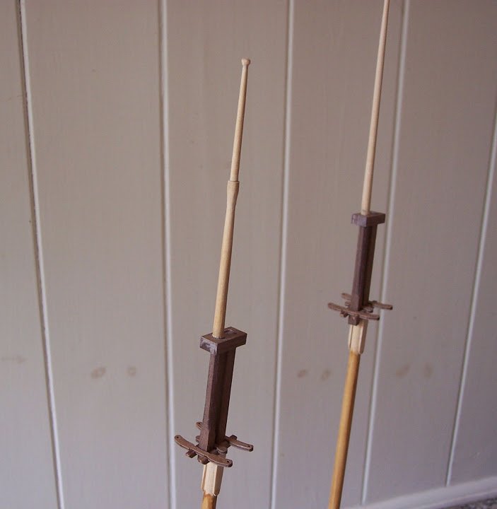
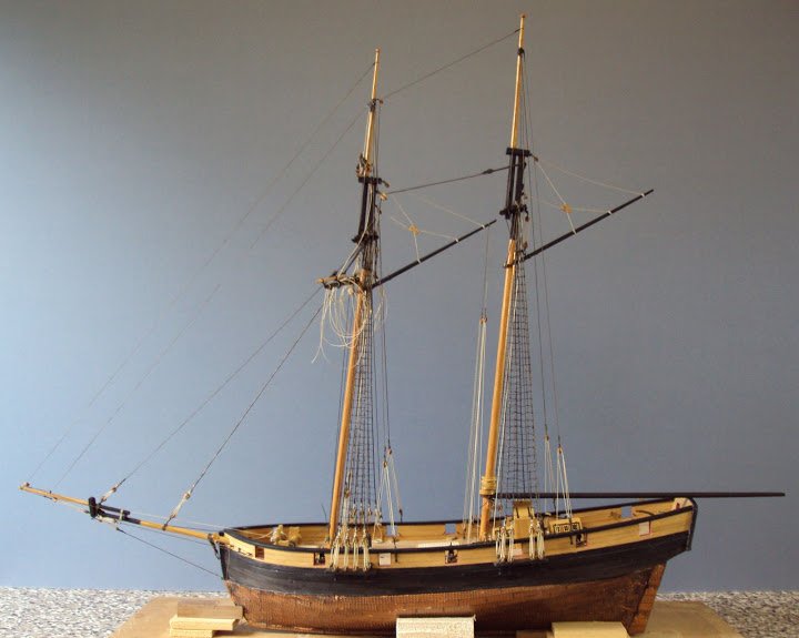
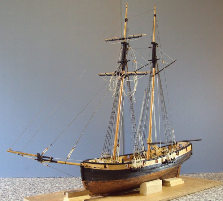
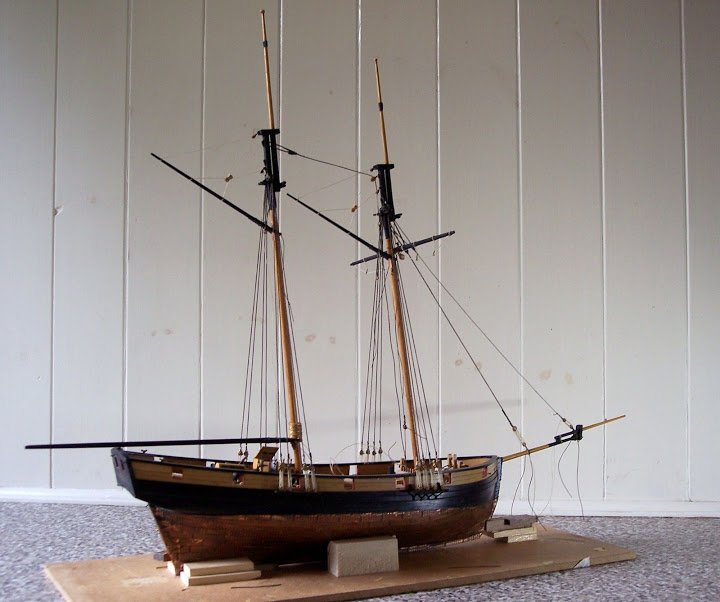
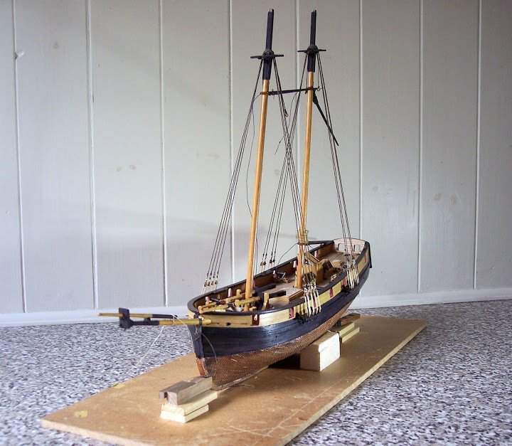
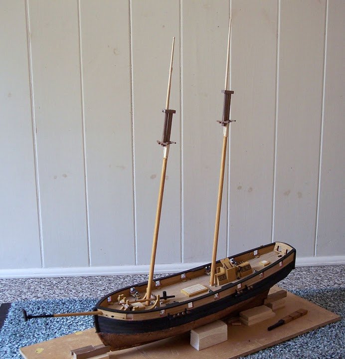
Dry fitting the topmasts before any finishing work can be done, the cheeks which show up white here support the trestletrees and give the correct angle.
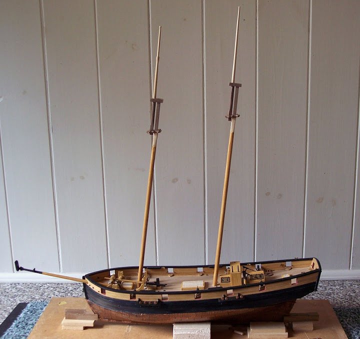
As can be seen she has quite a lofty rig, note the downward slope of the trestletrees which are parallel to the waterline, whereas the mast caps follow the mast rake.
Once I am completely satisfied with the fit I can fine tune the trestletrees and fix them in place. The topmasts will not be glued, both they and the mast caps are a snug fit.
I think I will however add a truck to the Main Topmast head.
B.E.
- Mirabell61 and maddog33
-
2
-
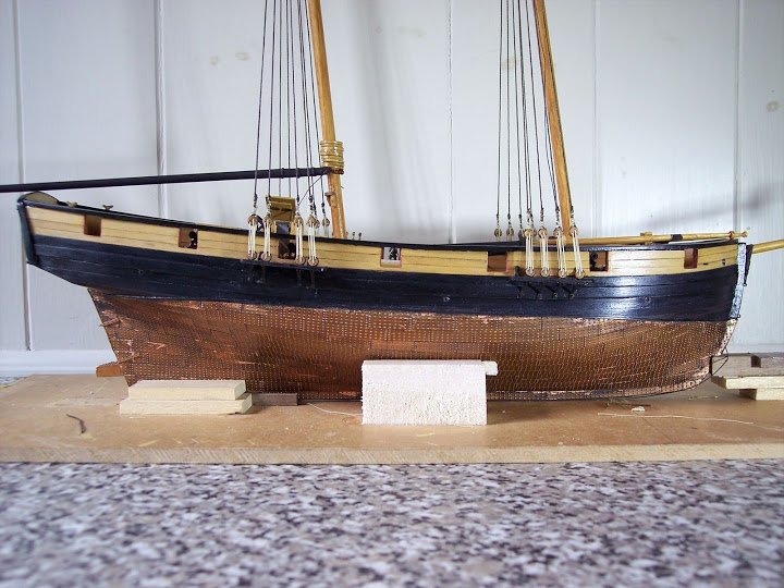
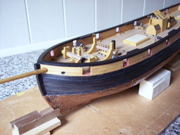
The Rudder
Usual blocky walnutty sort of thingy.
I looked at whether there should be any taper on the rudder both in fore/aft and top/bottom planes but decided that there was evidence that rudders remained the same thickness in many cases.
So blocky walnutty sort of thingy it is.
I started by fitting the tiller, I wanted to be sure that the angle of the tiller would be correct once the rudder was in place.
In considering the rudder, attention has to be paid to where it emerges thro’ the deck at the stern and how this is to be finished off.
In reality the rudder stock runs up thro’ the transom encased by a rudder trunk which prevents water ingress into the ship. At the bottom end where the rudder enters the hull a helmport or rudder coat is secured, and at the deck level a further coat is secured around the rudder head to prevent water running down the rudder trunk when the decks are awash.
I decided to give the upper end of the rudder stock a degree of round to facilitate turning.
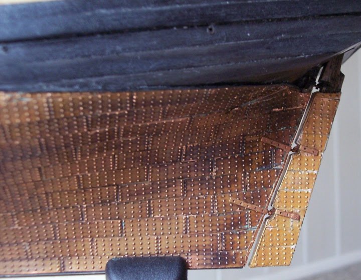
The rudder was copper plated and copper tape was used on the inward facing edge of the rudder.
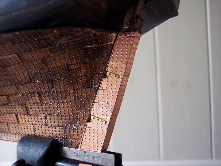
Close-up of the plated rudder showing the pintle straps in place, these need to be fixed first to judge the angles of the hull braces.
The difference in un weathered copper is clearly apparent.
The braces, gudgeons, pintles et al were supplied in etched brass. Jotika state that these should be painted black to represent iron.
Hmmmn iron stuff on copper plating in 1805, not sure about that,
 by that time a cuprous alloy was used for this stuff, whether there were exceptions on small vessels such as Pickle I don’t know, but in any event I ain’t painting mine black.
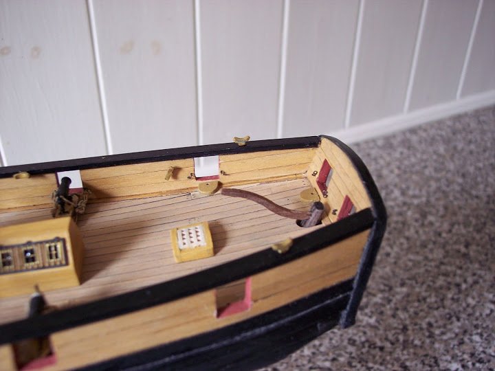
Some little fettlin’was required to get the tiller to sit at the correct angle for a 1:64 helmsman.
The trickiest bit is going to be getting the rudder to sit close to the sternpost when I fit the pintles and gudgeons.
Pintles, Gudgeons and Braces
An afternoons work to secure these, a little fiddly getting the pintles and gudgeons to meet up, and the straps at the right angle stuck to the hull without getting ca on the surface plating.
One of the scuppers can also be seen in this shot, four have been fitted along each side of the hull.
I have begun the weathering on the rudder but will stop the process a little earlier to give a lighter effect.
The tiller stands three scale feet above the deck, and Dick demonstrates the correct angle.
The rudder head was fitted with iron bands top and bottom of the tiller as strengthening pieces, as was the practice.
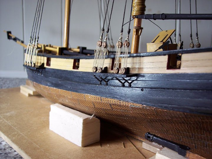
Channels or chain wales
These are pre-formed in 1.5mm stuff which is pretty bang on for scale.
I have added two knees to each channel for additional support. The Deadeye strops are brass etched and quite nicely formed if a little delicate. These fit into the notches on the channel face, and are then secured with a batten fixed across the edge.
Jotika suggest a 1.5 mm square piece of walnut for the batten but I went with a thinner piece of ebony stuff as I felt it looked better.
For the deadeyes I used a flatter pear wood version supplied by JB models, rather than the standard Jotika stuff.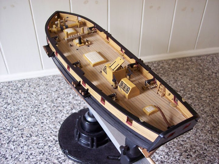
This basically completes the external fittings on the hull; I am toying with the idea of fixing side steps to the hull and short ladders fixed to the inside bulwarks, but there is time to think about this whilst I prepare the masts which is the next build phase.
Jotika suggest that building the Pickle should take between four and six months of evening work, hmmn, seems to have been a bit of slippage here, I’ve spent over five months already, and not restricted just to evening work, in fact I don’t do evenings, I prefer to work in natural light as far as possible.
B.E.
-
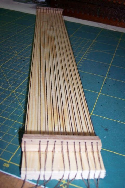
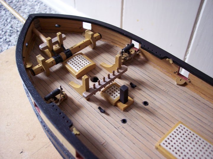
Whinging about the Windlass
The octagonal barrel of the windlass is provided by a number of octagonal discs which when fed onto a central spindle with provided wooden pawl rings make up the barrel. There are 11 of these segments plus spares.
Problem is the ones I got were the very devil to get the octagons to line up cleanly and I wasn’t over impressed with the result, partly due to the differing shades of the walnut segments. Jotika intended for the thing to be painted red ochre.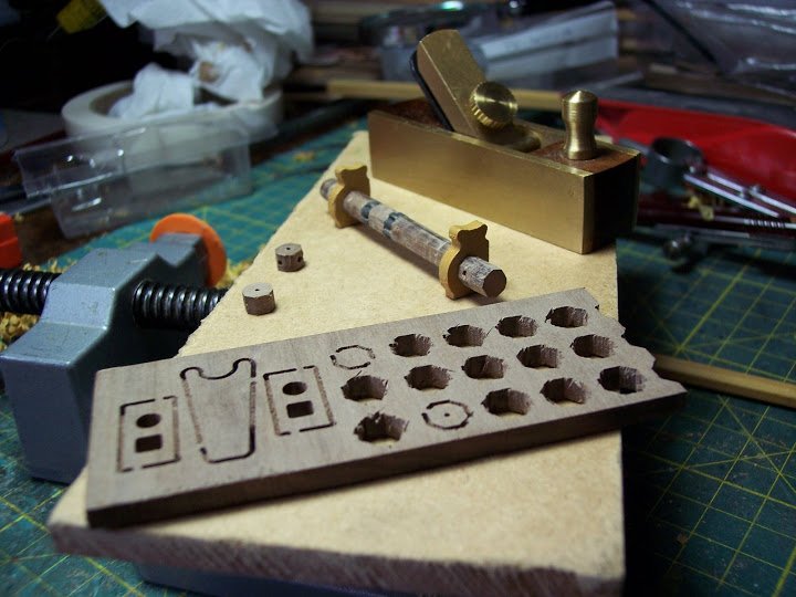
The sectional make up of the Jotika barrel just doesn’t look right to my eye and the single diameter along its length gives the impression of a pencil chopped up and glued together again, rather unrealistic, and coupled with the deficiencies in my skill at assembling the thing, I resolved to do better.I wanted a clean bare wood barrel with distinct clearly defined octagonal sections, and with a degree of tapering from the centre section down to the warping heads at either end.
Salvation came in the form of some old stock 5mm boxwood square section that just needed converting into an octagon.
My little Rosewood mini plane was just right for the job.
For style I took the drawings of the windlass given in the AOTS book Alert.
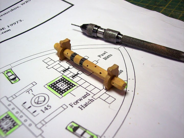
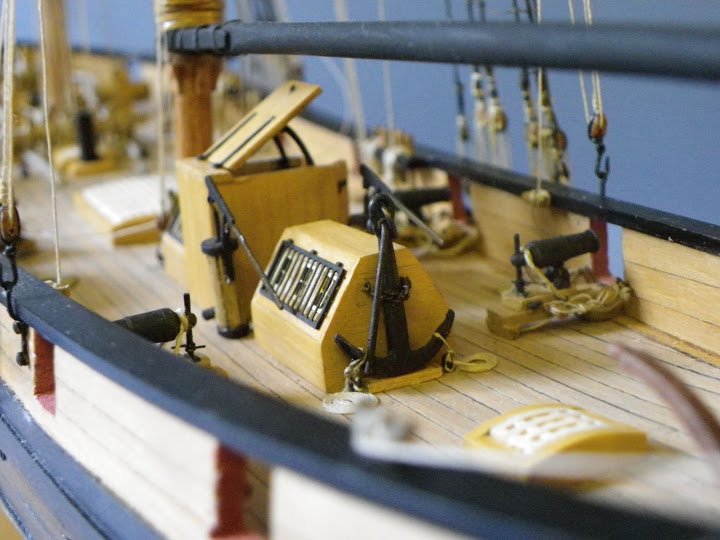
Overall it has a more authentic look and will better match the other deck fittings on Pickle. It took me three attempts to get something I could live with but here at last the assembled but unpolished windlass.
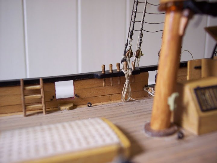
I see a bit of roughness on the starboard standard that will need attention, and I think I may add metal bands each side of the iron pawl rings.Fixing bits and pieces
Three major deck items, the Fore Bitts, Windlass, and Pawl bitts require fixing to the deck by means of pins inserted in the bottom of the standards, and thro’ a corresponding hole in the deck.
Tricky business this to get the corresponding holes in the right place so that the items are fixed in the correct positions and square to the central line of the ship.
The bitts in particular require firm fixing against the pull of the rigging to come later, and the pawl bitts against which the bowsprit is secured.
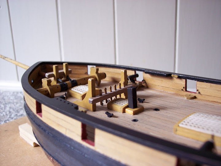
two minds about those belay pins, they look a little over-scale to my eye.
I modified the coamings around the Galley flue, didn’t like the Jotika 1.5mm walnut strip arrangement.
In any build there are
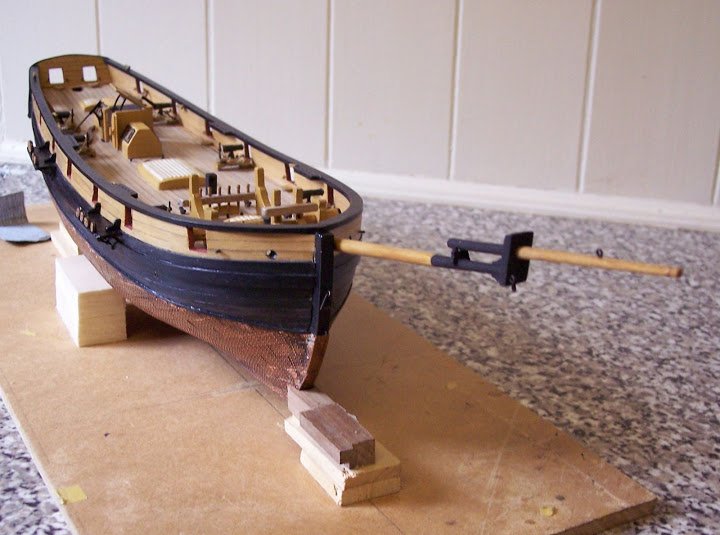
several critical points that could affect the end result, with Pickle one of them is drilling the hole thro’ the bulwark to take the bowsprit.
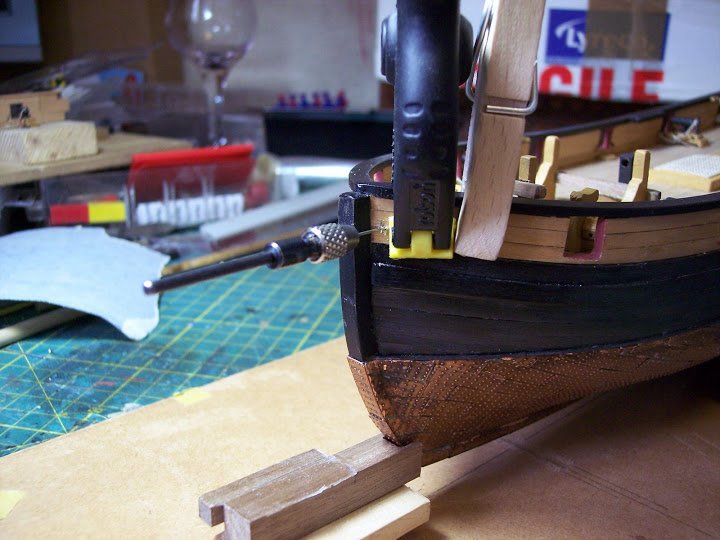
A bit scary this cutting thro’ the neat planking one has taken so much trouble over – have I got the position dead right, will it line up with the pawl bitts, must avoid splintering the internal planking when drilling.
Who said model making was a relaxing activity.
This is not the real bowsprit but close enough for fitting purposes, and things seem to have turned out ok.
In the Same vein the hawse holes have to cut thro’ the bulwarks, 2mm according to Jotika to take a 1.3mm diameter cable.
I was curious to see how this related to given formulas for calculating the cables and hawse sizes.
For cable sizes this is ½” of circumference for each foot of breadth of the ship.
Given a width of 20’ 7½” this equates to a 10.3” circumference cable, which at scale works out at 1.3mm diameter.
Spot on Jotika.
The hawse hole formula is diameter of cable x 9/4 = 2.92mm. Nearly a third larger than that suggested by Jotika.
I enlarged the hole size to 2.5mm which looked better in relation to the 1.3mm diameter anchor cable.
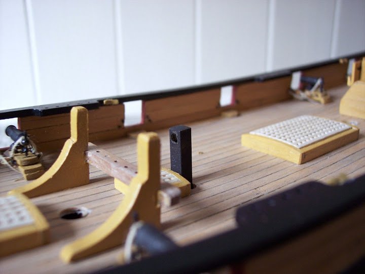
Two more holes to drill in the deck, Jotika calls them Navel pipes, down which the anchor cables pass to the cable tier.
Now I’ve not heard this term before in period ship modelling and it doesn’t seem to be mentioned in any of my reference books save the Oxford dictionary of ships and the sea.There is no reference to Navel Pipes in the Global Schooner by Marquardt or the Cutter Alert by Peter Goodwin, two specific references I am using for this build.
Still I have gone with the Navel pipes enlarged to just over 3mm to take short lengths of aluminium tubing, chemically blackened, and inserted flush with the deck.
Along with various eye bolts and cleats that now finishes the internal fittings on Pickle.
Next up the external fittings and making the rudder.
B.E.
- Mirabell61 and Mr Whippy
-
2
-
-
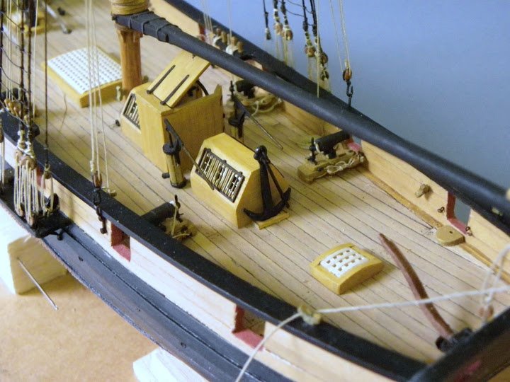
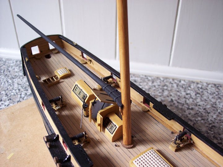
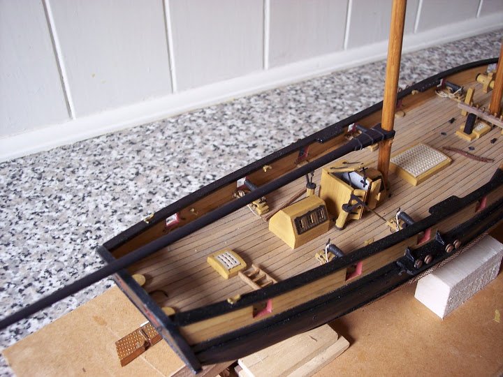
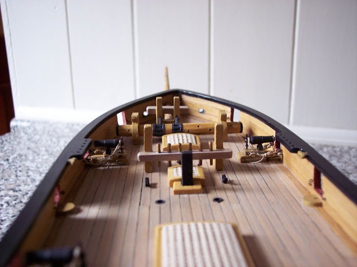
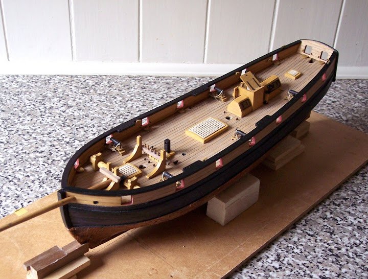
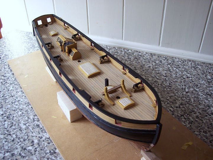
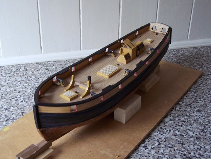
Skylights and companions
All the deck fittings etc; provided are in walnut. Jotika intended them to be painted red ochre, or left natural.
This presented me with a problem as I wanted the deck fittings to be yellow ochre, represented by boxwood.
Some of the fittings have been completely replaced but others such as the carronade beds and bitt standards I did not want to go to the trouble of replicating.
I spent some little time concocting a mix of Ronseal light oak varnish with the merest touch of Admiralty yellow ochre water based paint to create a matching boxwood finish.
I am quite pleased with the result.
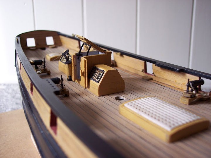
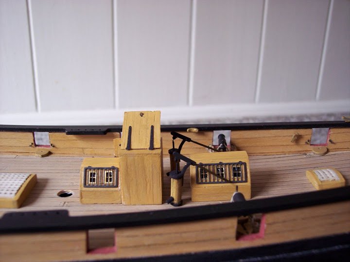
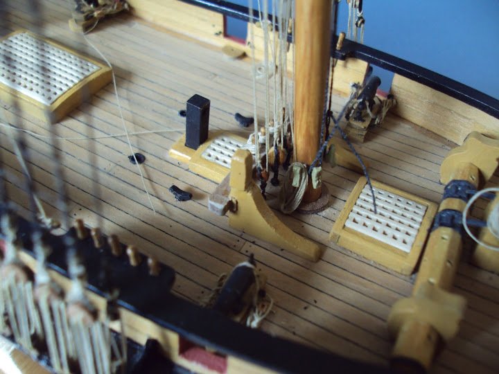
The Skylights and Companionway are supposed to be assembled from the ubiquitous walnut sheet and then be painted red ochre, but I replaced mine using boxwood strip to create a boarded effect.
The brass etched window frames I left unpainted as I rather liked them, and I expect them to tarnish over time. The iron protective grills were chemically blackened.
Rather than use the provided acetate for glazing the windows, I opted for Humbrol clear fix as the panes are very small.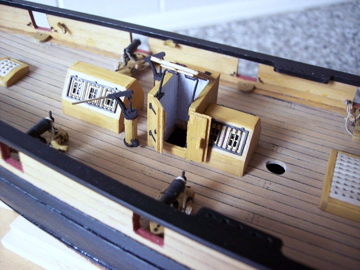
The companionway was also boarded, with the interior boarding whitewashed to provide a contrast. The kit over-scale walnut doors were replaced with boxwood versions.
The completed items were then varnished with my ochre/varnish mix.
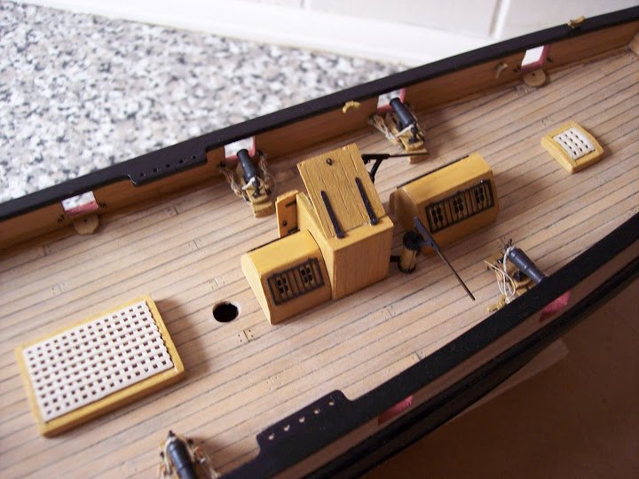
Elmtree pumps
So often these items provided in kits are somewhat clumsy and overscale but Jotika have provided quite fine pump handles in etched brass to complete the ensemble.
The pumps do not stand vertically on the deck but are canted slightly and would in reality converge towards the centre line of the bottom of the ship.
To this end I inserted lengths of brass tubing thro’ the deck into which micro brass tubing forming the plungers fit.
I fashioned the pump bodies from a bit of round stuff, but tarted them up with iron bands formed from the brass fret surrounding the 0.3mm eyelets, and a bit of brass tubing.
The galley chimney.
I replaced the suggested 4x4mm walnut strip with a piece of square section brass tubing, chemically blackened.
I had toyed with the idea of providing a more fancy flue, but decided on a small vessel such as Pickle, plain and simple would be appropriate.
I still have to make coamings to go around the flue but I can’t make my mind up at present as to the section I prefer.
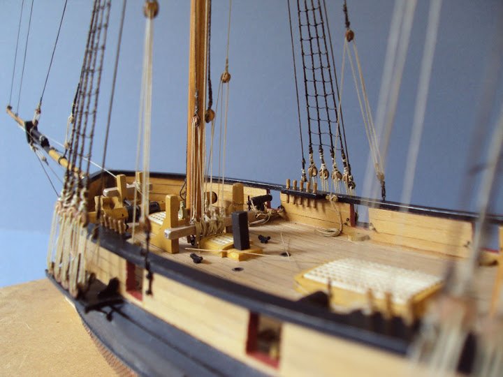
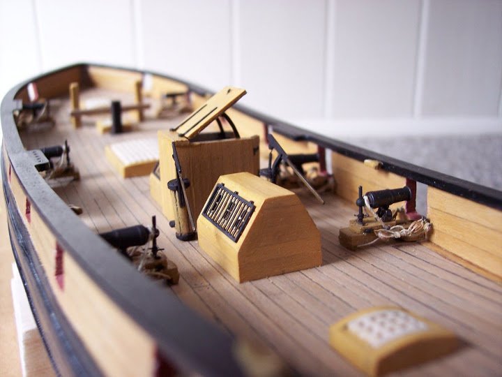
Here’s where I am now up to, the hatches/grating, and main deck furniture have been fixed, I will not permanently fix the pumps until later in the build, they are quite delicate and experience tells me they are perfect snag magnets.
To be cont'd
B.E.
- Mr Whippy, Mirabell61 and Oeli1964
-
3
-
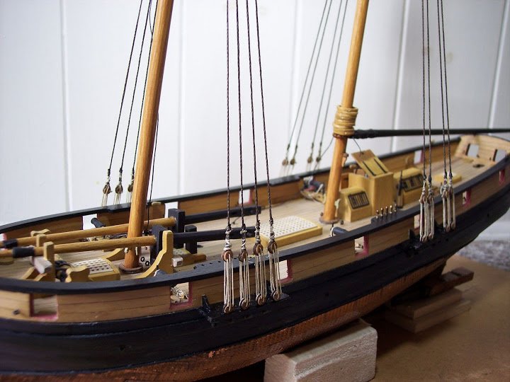
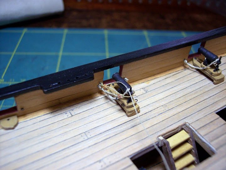
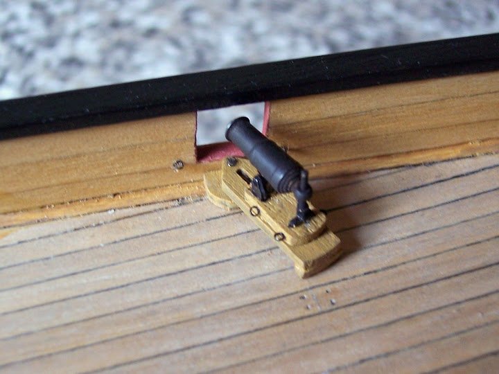
Now the tricky bit – the side tackles
I was in two minds about the side tackle rigging, Jotika show them with the loose ends coiled on the deck.
This is a traditional way of displaying the falls of the tackles on models, but I somehow doubt that this is how it was done in practice in a working boat situation, particularly a hard worked vessel such as Pickle.
The provided blocks look too clumpy for my taste , and I have replaced them with 2mm Pear wood blocks supplied by JB models.
The Jotika 0.1mm line for the tackles also looks over scale compared to the breeching rope, but in any case I’m not a fan of Jotika line and it has been replaced.
I stropped the blocks with 34 gauge wire, the tails of which formed the fastenings either end.
I finally decide to seize up the side tackles, much in the way of this shot of the 68 pounder on Victory.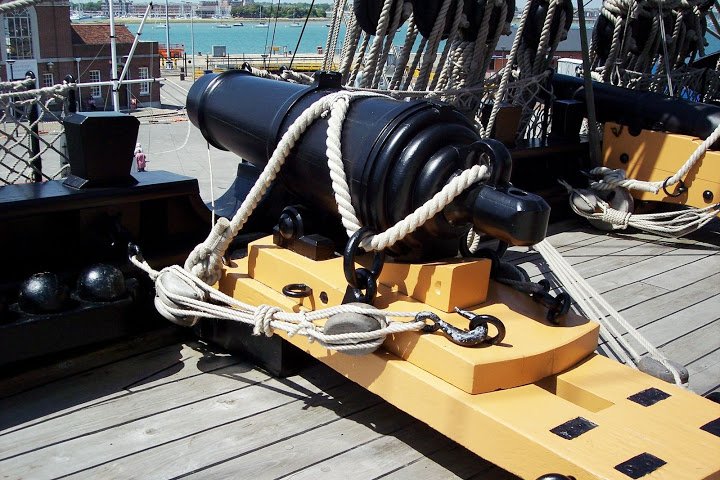
Given the scale I think the tackles look neater, I didn’t want the tackles to dominate the carronade, as they appear to in the Jotika photo.
To make the side tackles a little jig was required to hold the blocks the correct distance apart whilst the lanyard is fitted. Using 0.1mm diameter Amati line, the lanyards are working versions.
Rigging the tackles
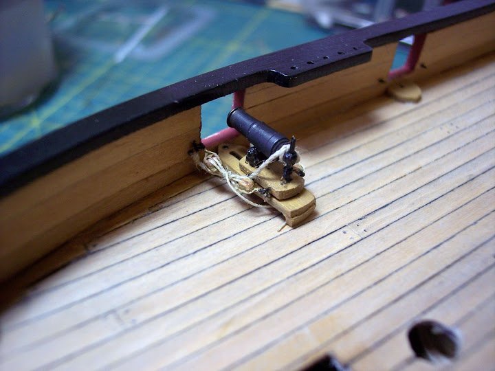
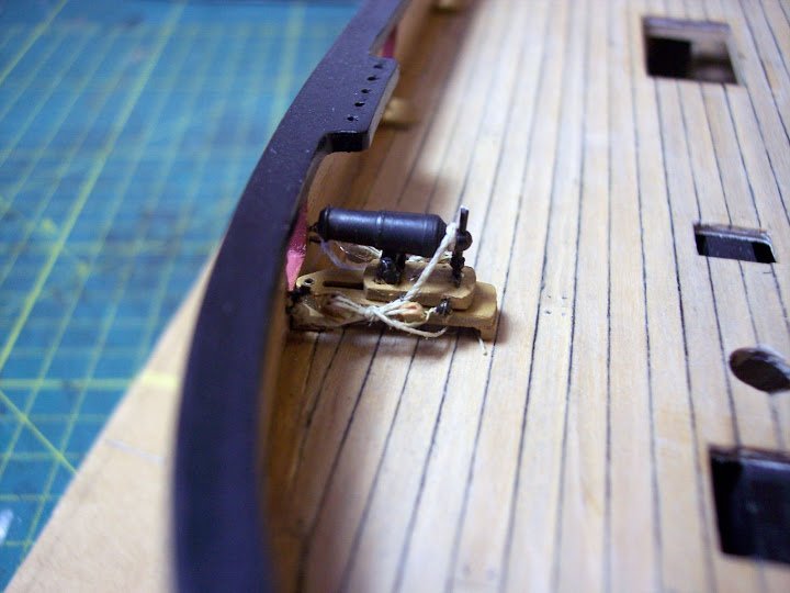
I am pleased with the result compared to the Jotika suggested arrangement, and once completed I can get onto attaching the other deck fittings which I have mostly already prepared.
-
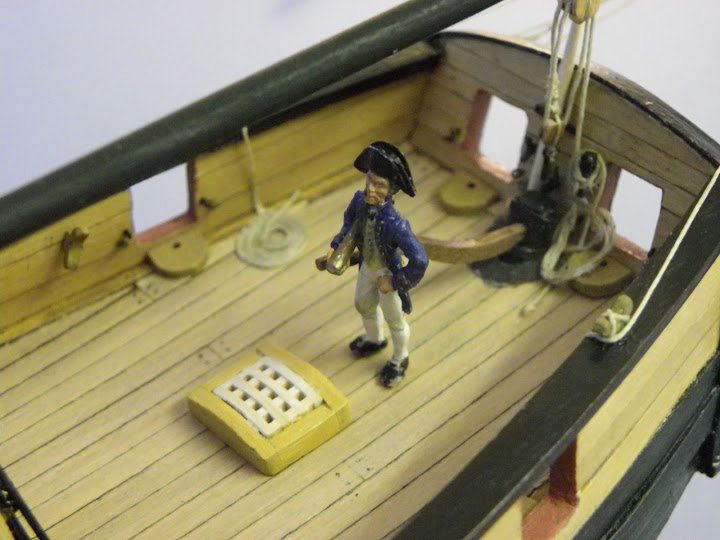
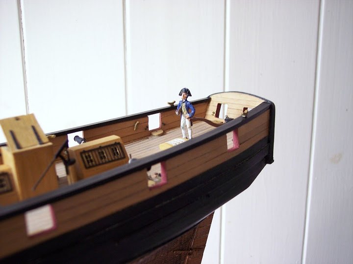
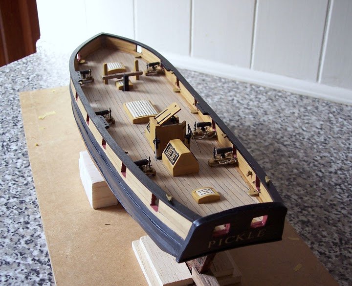
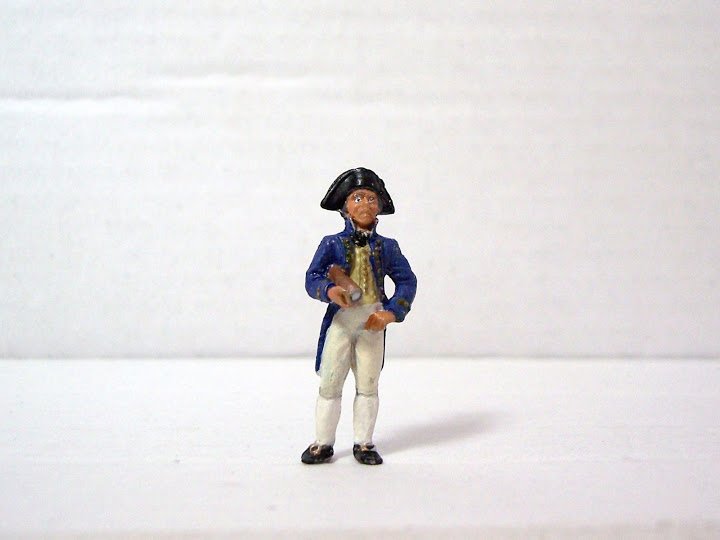
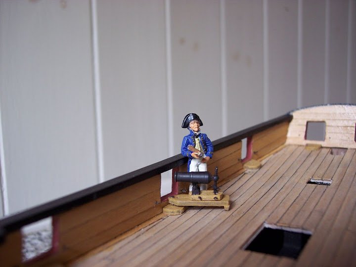
Introducing ‘Dick’
Aka John Richard Lapenotiere, of Pickle fame. I needed a mini Pickle Captain and here he is. Someone to give scale to the model and assist in assessing the scale validity of the fittings.
Looks a little older than his thirty five years but then he’s had a hard life, tossing about in smallish boats, constantly wet, ’tween decks height of only 4’ 6” when he’s 5’8” Not much influence, not many mates by all accounts, but now a life chance with the prospect of carrying the news of Trafalgar back to England, the lure of promotion and the £500 quid he will receive if only he can keep ahead of that b*****d Sykes of the Nautilus who is determined to get there first.
Hand over those dispatches says Sykes, no way says brave Dick I’m under direct orders of Admiral Collingwood to deliver my dispatches by hand so I respectfully suggest that you do one.
Not to be put off the dastardly Sykes races our hero all the way to England but fails by minutes to beat him to the Admiralty.The rest as they say is history, so my mini Dick will stand proudly on the Pickle’s deck casting (no pun intended) a critical eye over progress. He has the look of a rather a severe critic about him to me.
Dick is an Amati 25mm cast metal figure, looks a bit scary under the digital eye but is ok at normal viewing perspective.
I think they modelled him on Arthur Wellesley ,a rather arrogant look and he does have that fine hooked nose.
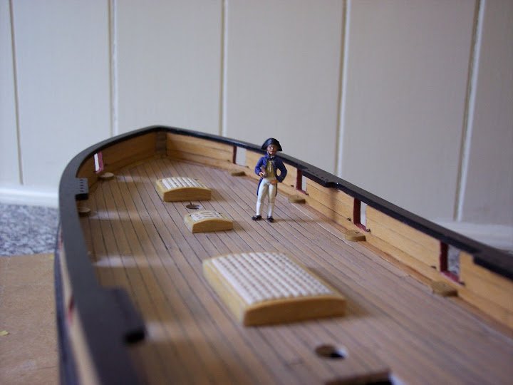
Dick will continue to make guest appearances in various progress shots to give a human scale to proceedings.
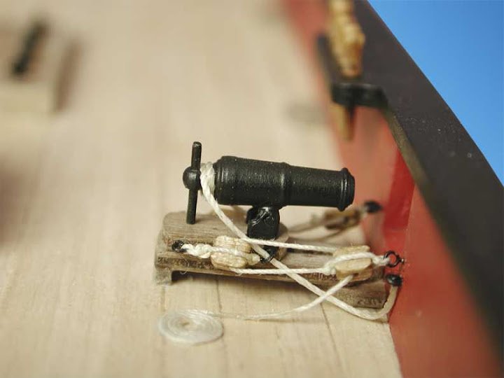
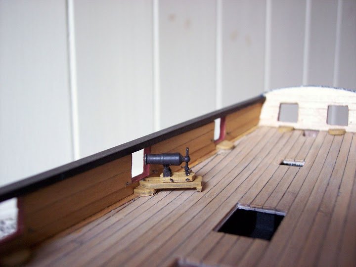
Rigging a Carronade – thoughts on the Pickle kit
Been in the back of my mind for a while, I wasn’t over impressed by the Jotika arrangement as shown in their build photos.
Breeching rope lead ring is I think too far forward, a consequence perhaps of the over scale blocks to the side tackles. The breeching rope has an unnatural lie and seems merely to be pushed under the bulwark ring.
To assist in the tackle forming I rigged up a spare carronade in a mock gunport, to see how things fared.
With the rigging tackle so small I find it easier to work out a gun rigging strategy with a mock-up rather than go straight in on the model.
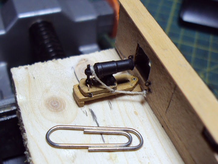
The breeching ropes of 0.5mm Ø line are simply knotted to the bulwark rings and are sealed with dilute pva before trimming.
A small paper clip gives scale to this ‘toy’ carronade.Here a couple of shots of the carronades in-situ and the Breechings fitted.
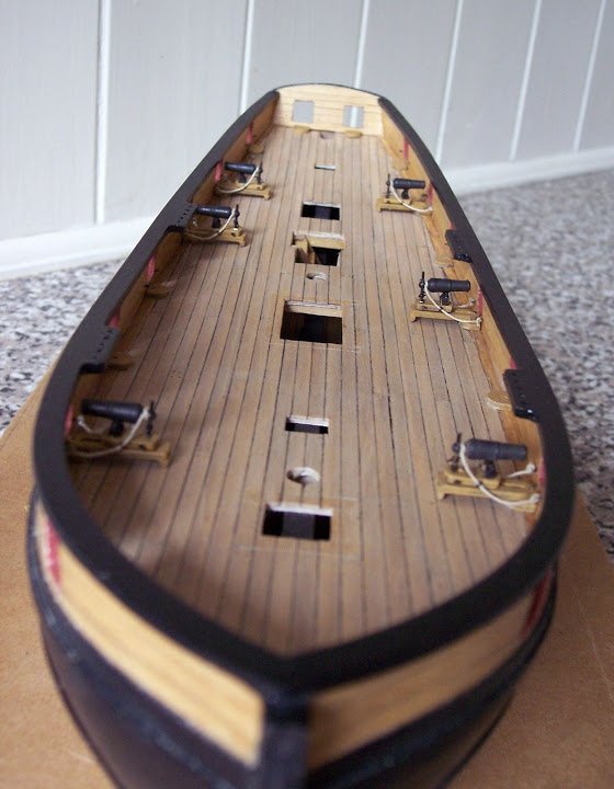
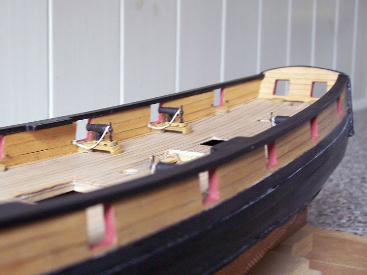
I can now proceed with the somewhat testy rigging of the side tackles.
B.E.
-
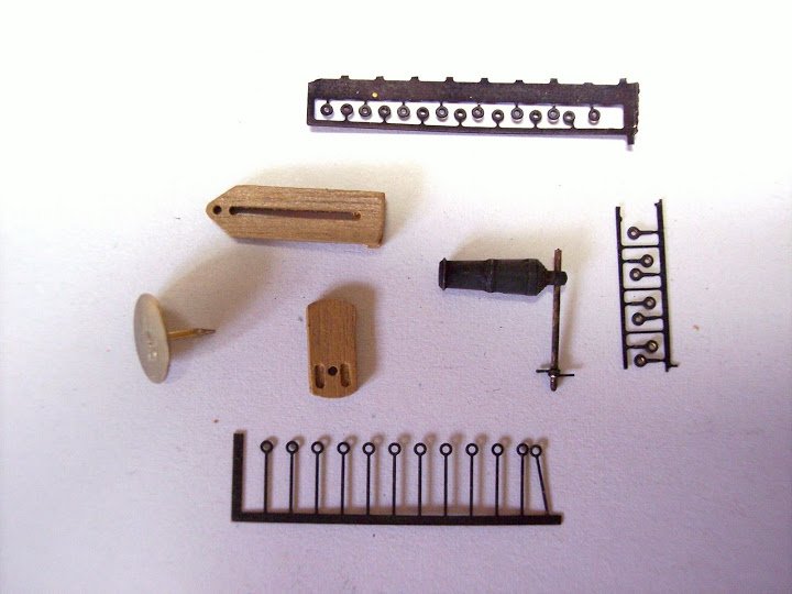
Assembling a Carronade.
This is one area of the build that seems to present Pickle builders with problems, trying to assemble the trunnions of the Pickle Carronades.
The instructions really should carry a mental health warning.
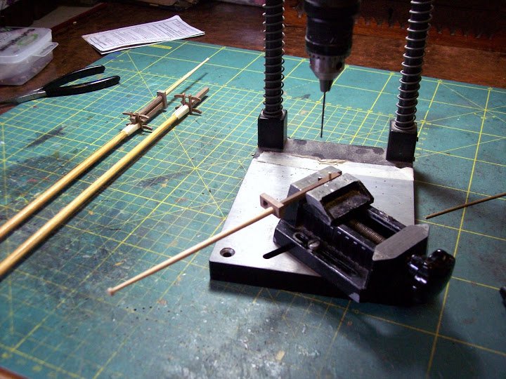
These are tiny beasts consisting of two trunnions, a spigot, two bearings, all threaded onto a piece of 0.5mm wire and assembled within a space of 1.5mm between the trunnions.
Assembly without devising a mini jig would I think prove very, very, frustrating.
A sense of the scale of the things can be gathered from the following photos.
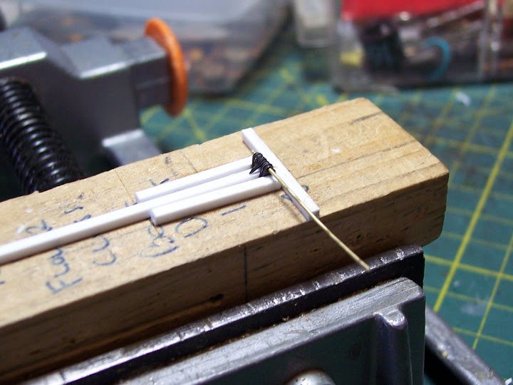
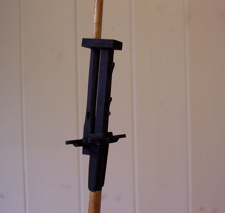
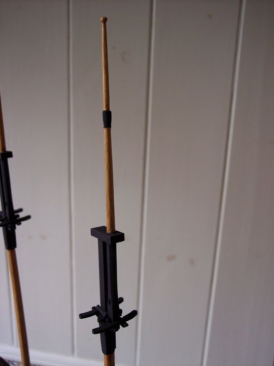
The jig to hold the trunnions.
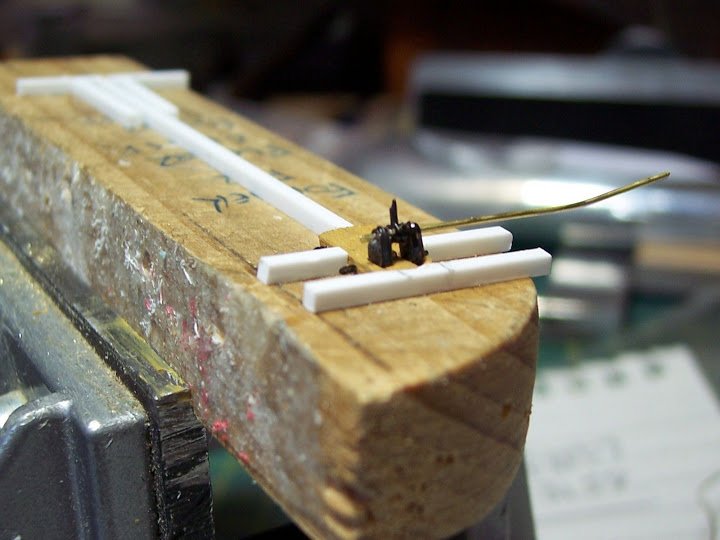
The assembled trunnions attached to the slide bed.
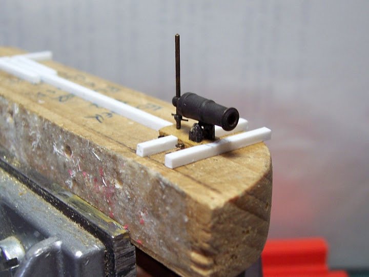
The assembly completed.
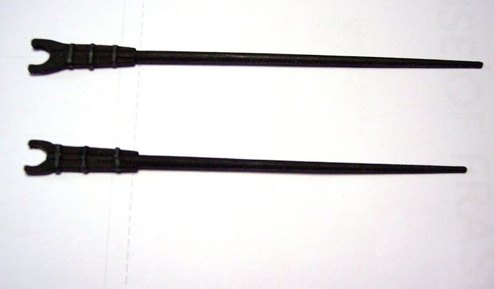
I wasn’t too impressed by the use of a length of 0.7mm wire to represent the elevating screw so I added a small refinement in the form of turning bars, and a metal plate to sit the elevating screw on.I also moved the breeching rope lead ring slightly further back than suggested by Jotika, I felt it gave a better lie to the rope.
These bijou carronades along with all the other brass etched fittings have been treated with Carr’s Blackening for Brass, having first been dipped in acetone and scrubbed with an old toothbrush, well I think it was an old toothbrush, anways, I know it wasn’t mine.
Even so the inevitable handling in assembly results in some loss of black, and paint touch ins are necessary.
Assembly of the first carronade took all of this morning including the jig making.
Fortunately there are only six carronades supplied with Pickle, although other sources suggest she carried eight. Having assembled one I am sorely tempted to oik four of ‘em overboard as Lapenotiere, did on his voyage.
At full scale these twelve pounder carronades are incredibly small when one is used to looking at the sixty eight pounder smashers on Victory.
Full size they would be a mere 2’2” compared to over nine feet for a carriage mounted long gun of the same calibre, and only a fraction of the weight. Even so they do look very insignificant on the Pickle.
Here’s a shot of ‘Dick’ apparently dwarfing a carronade, but the relative scales are correct.
B.E.


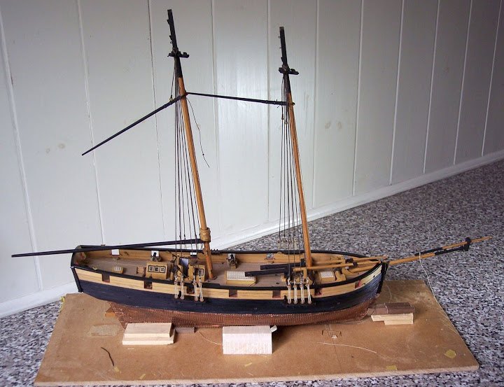
Pickle by Blue Ensign - FINISHED - Caldercraft - 1:64 scale
in - Kit build logs for subjects built from 1751 - 1800
Posted
A few odds and ends
Rudder coat and pendants.
I usually make rudder coats out of micro-porus tape as it has a sort of canvas finish to it and has the added advantage of a sticky back.
Rudder coats are a sort of bell shape in plan but cutting a pattern for a particular ship is a matter of trial and error.
There should be an element of ‘bag’ in the coat to allow free movement of the rudder
This is difficult to achieve without padding out the interior, I use a little cotton wool off a cotton bud for this purpose.
After this it is just a matter of teasing it into shape around the transom and rudder.
The canvas was tarred to waterproof it as much as possible and I have represented this with a black grey finish.
The Rudder pendants
Evidence is that even smallish vessels like Pickle would have had some system for retaining the rudder after all loss of rudder was no small matter.
I could not find any detailed information exactly how the pendants and chains would have been fitted on Pickle; similar smallish vessels are shown with the pendants taken up over the transom and secured to cleats on the inside. This method would foul the stern gunports in the case of Pickle.
I fitted chains to eyebolts secured in the rudder and to eyebolts in the lower transom, and contented myself with this arrangement for the present.
Anchor buoys
These too are an essential part of a ships equipment, they need to be clearly seen on the water, and the standard size is 54”x 30” with something in excess of 100’ of line.(475mm)
Smaller vessels such as Pickle would have had a smaller version and I scaled mine down to 36” x 20”
I made an egg shaped core from the cone shaped tips of two cheap bic prop pencils and planked these with styrene strip.
With the addition of eyebolts either end and 0.25mm line to form the slings and hoops and the job’s done.
I don’t normally adhere to scale lengths of line but in this case I have measured out 18 fathoms of line (scale of course) to coil on the shrouds.
Nearly there