
.JPG.ca33079f5815b861e67b9c2cccd37982.JPG)

Blue Ensign
-
Posts
4,536 -
Joined
-
Last visited
Content Type
Profiles
Forums
Gallery
Events
Posts posted by Blue Ensign
-
-
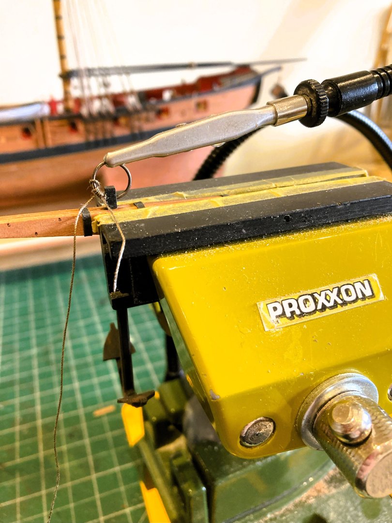
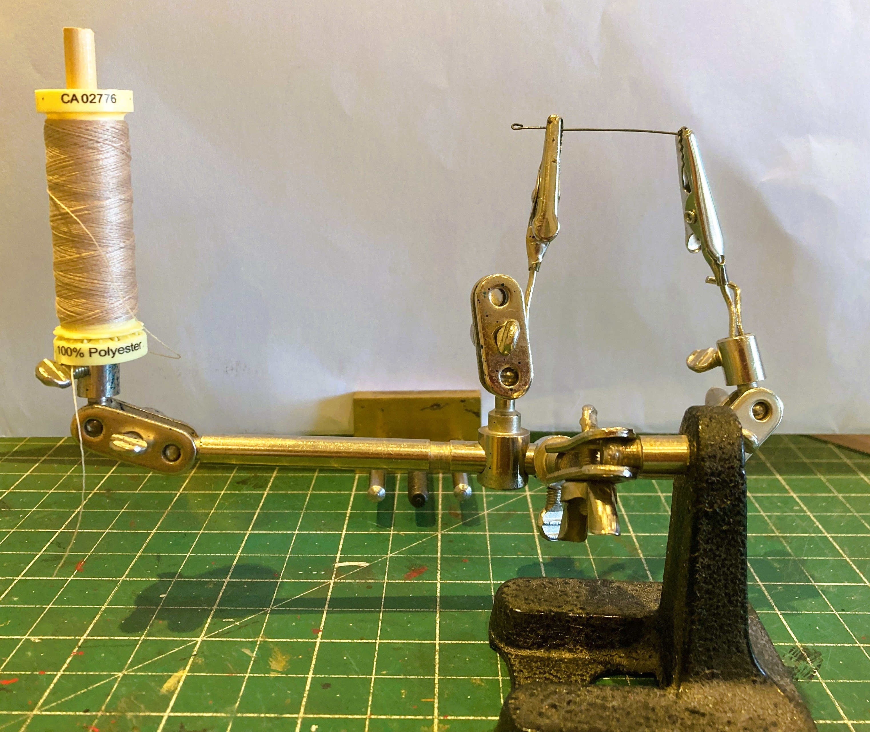
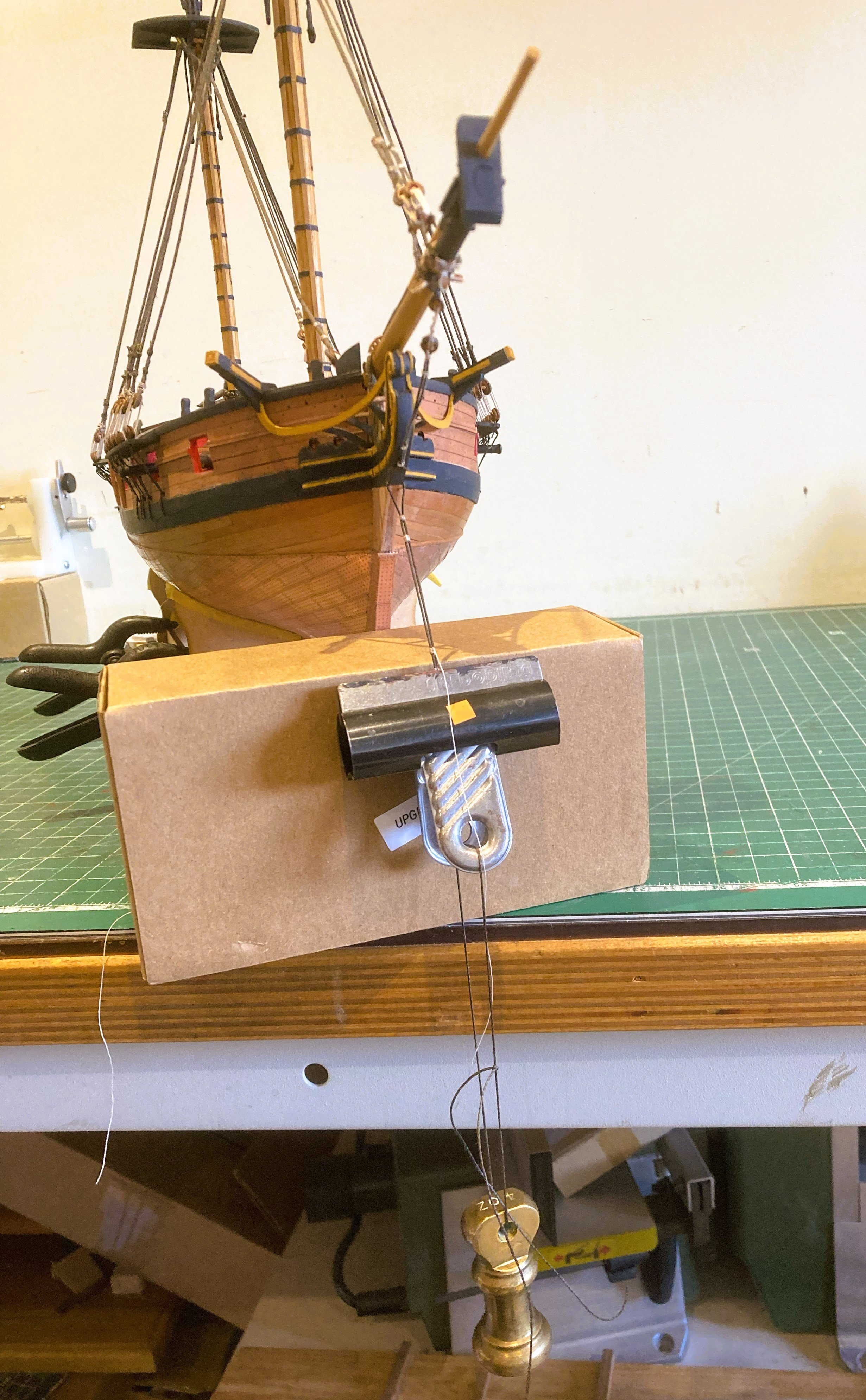
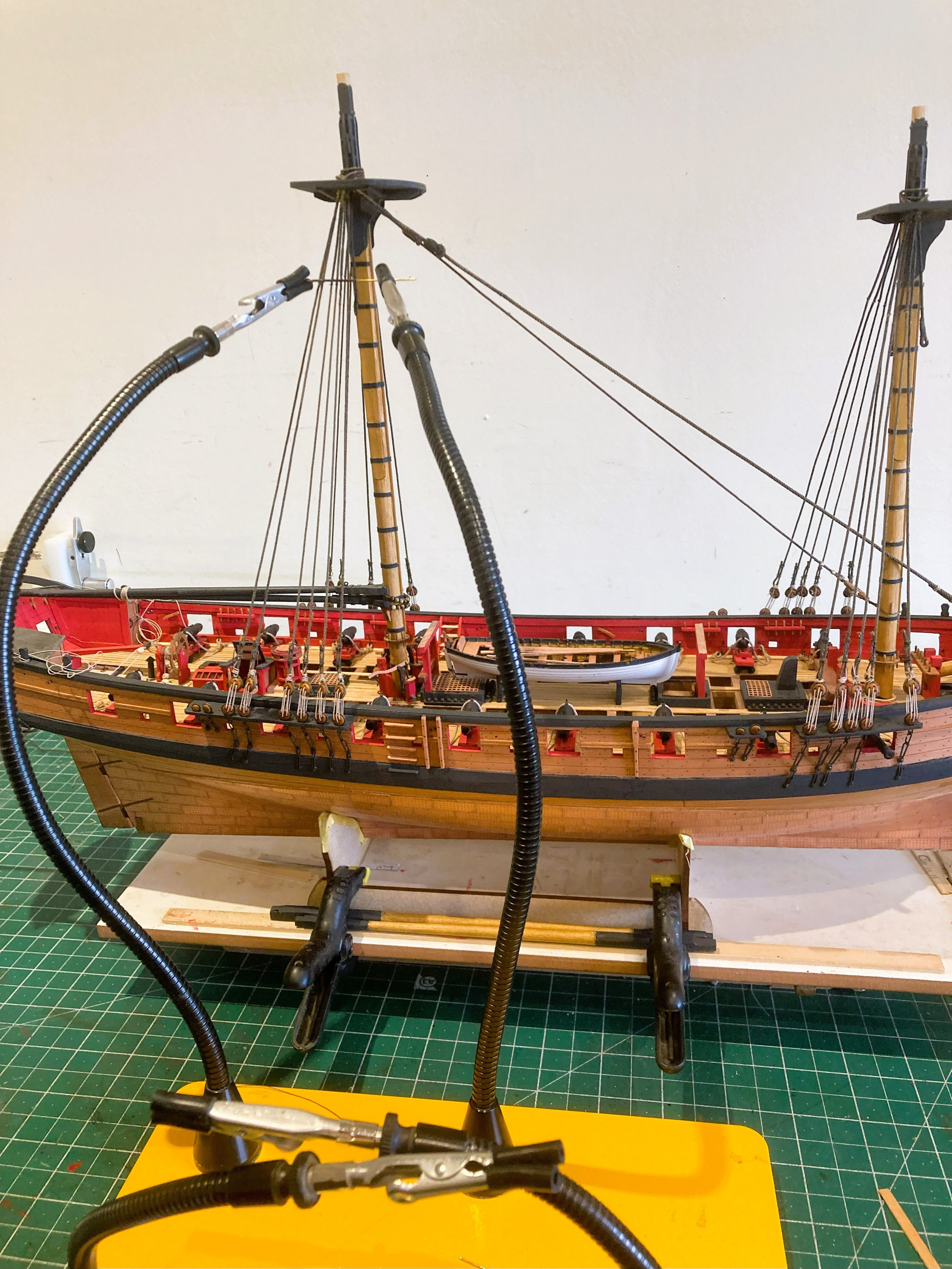
Ah if only it were that simple Ron, all the best riggers set up with oars don’t you know.😉
ps that’s oars with an ‘o’ not a ‘w’
M.
-
-
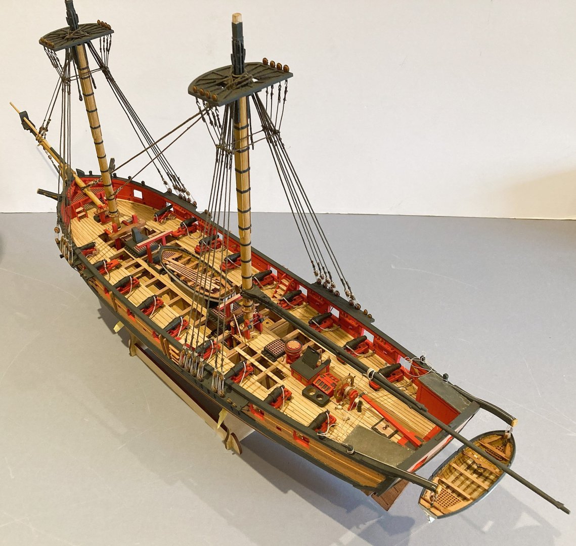
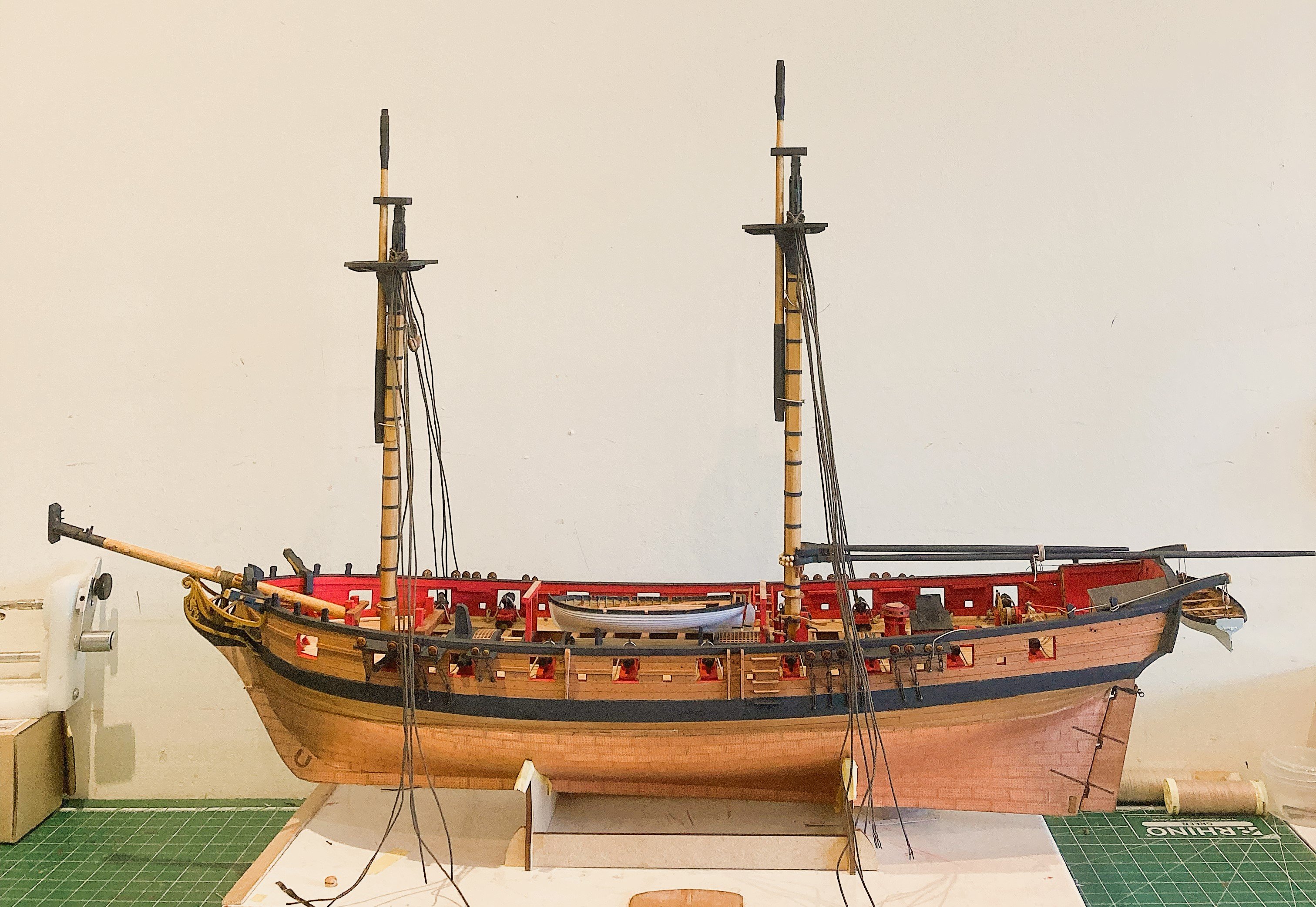
Post 104
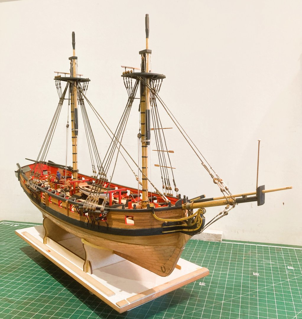
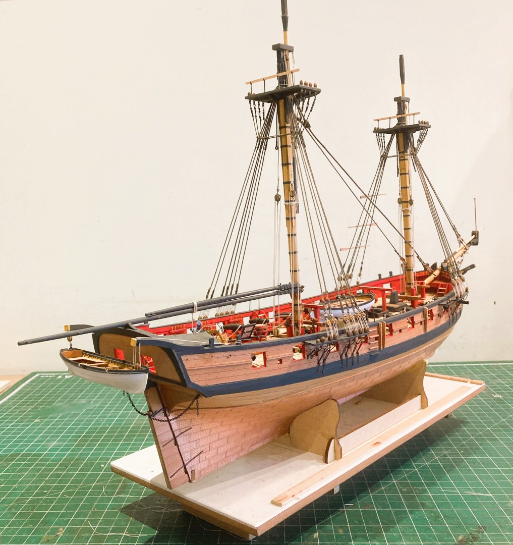
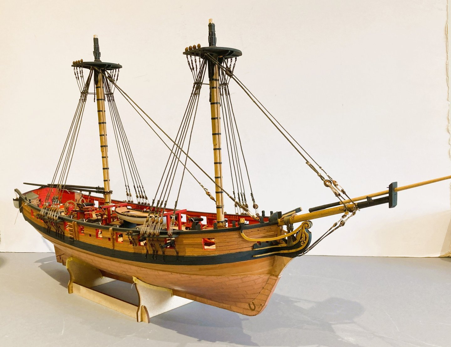
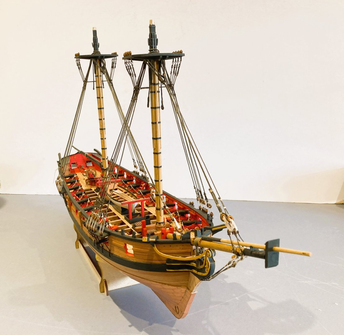
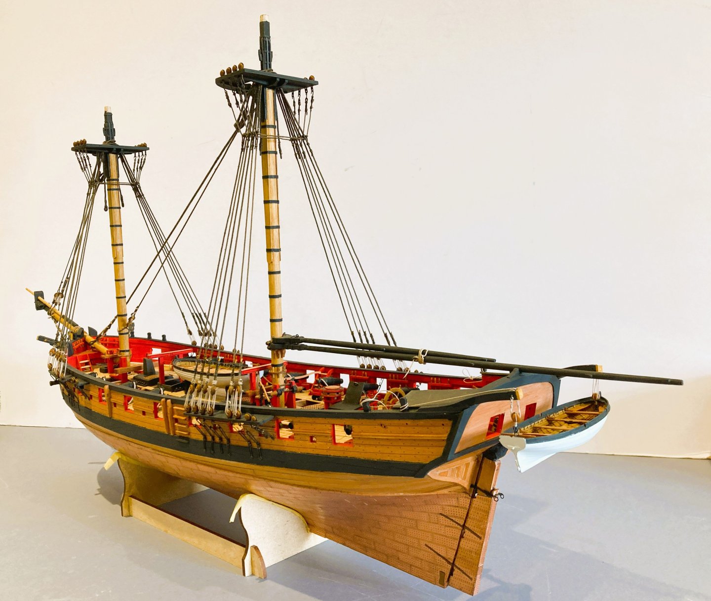
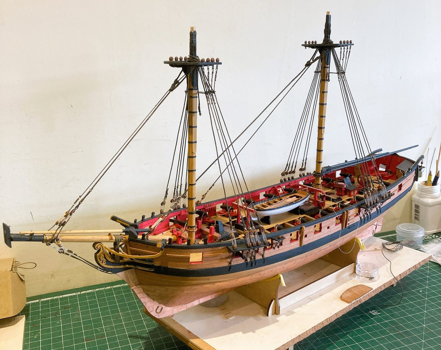
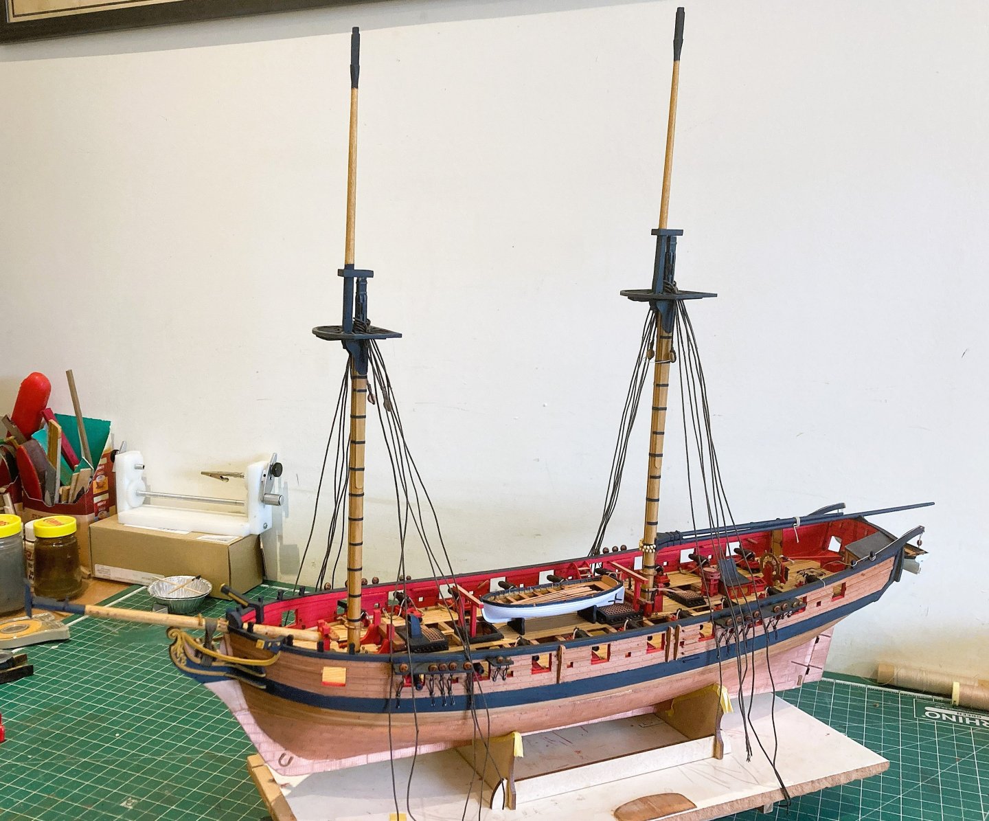
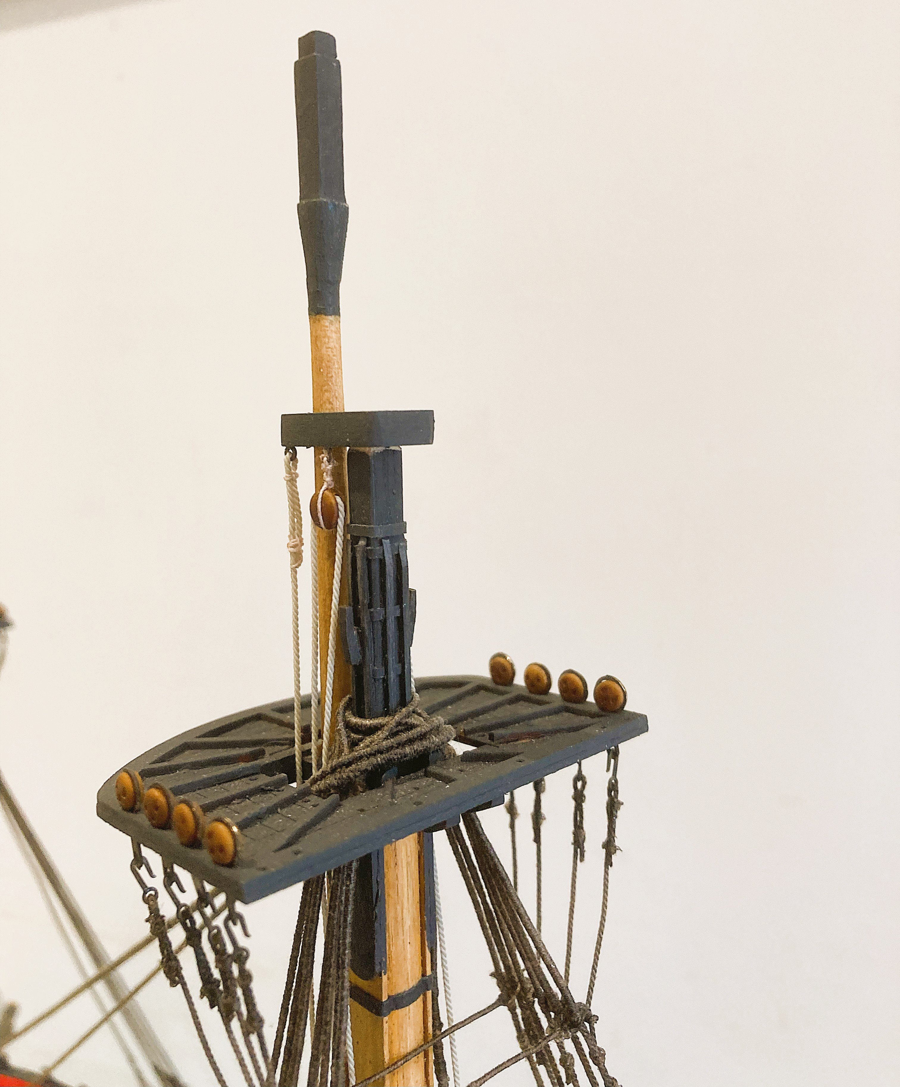
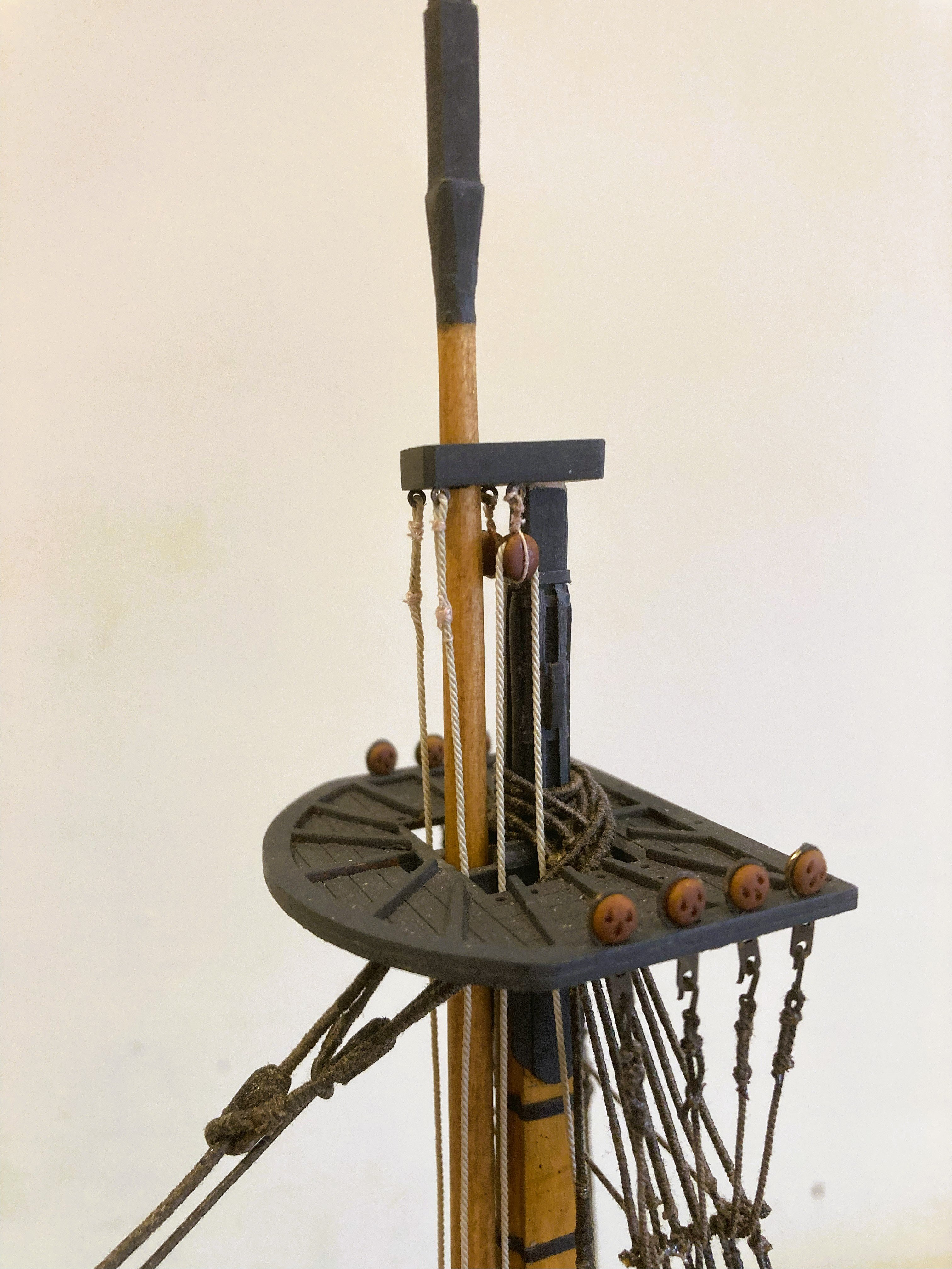
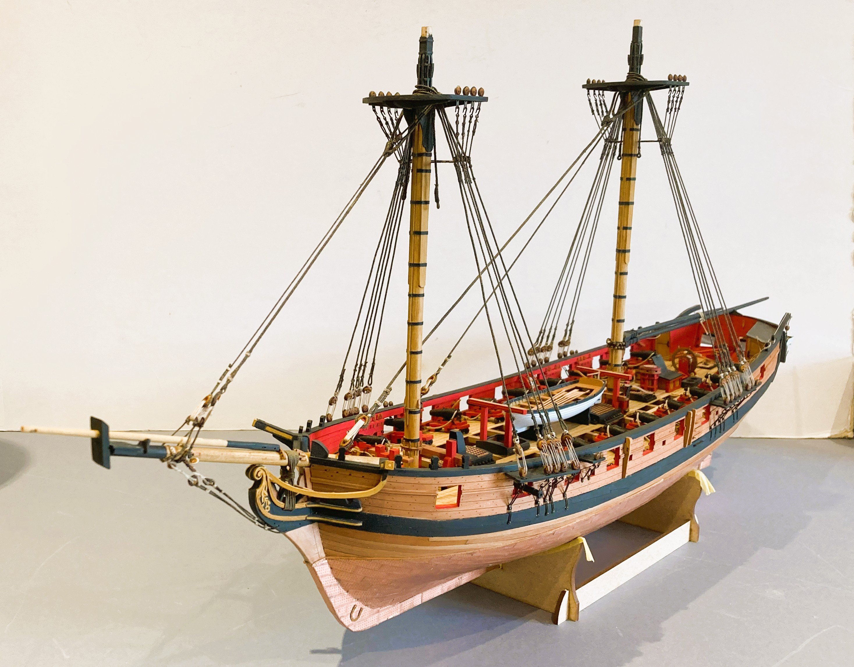
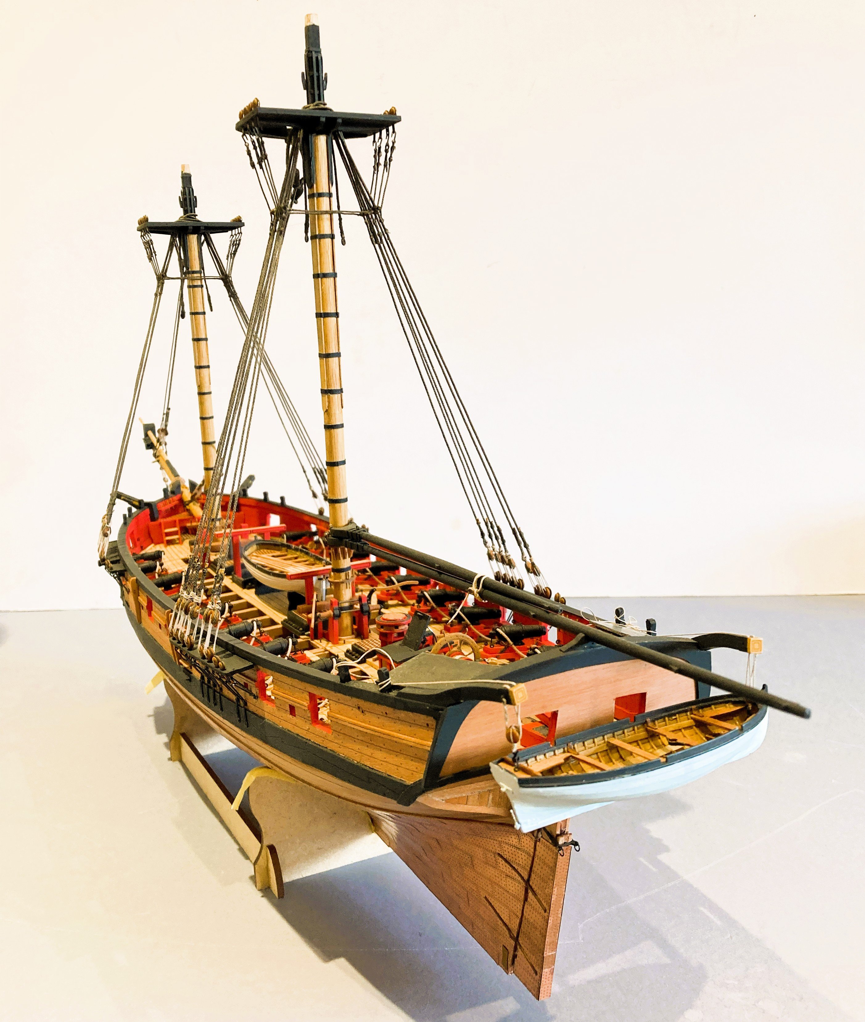
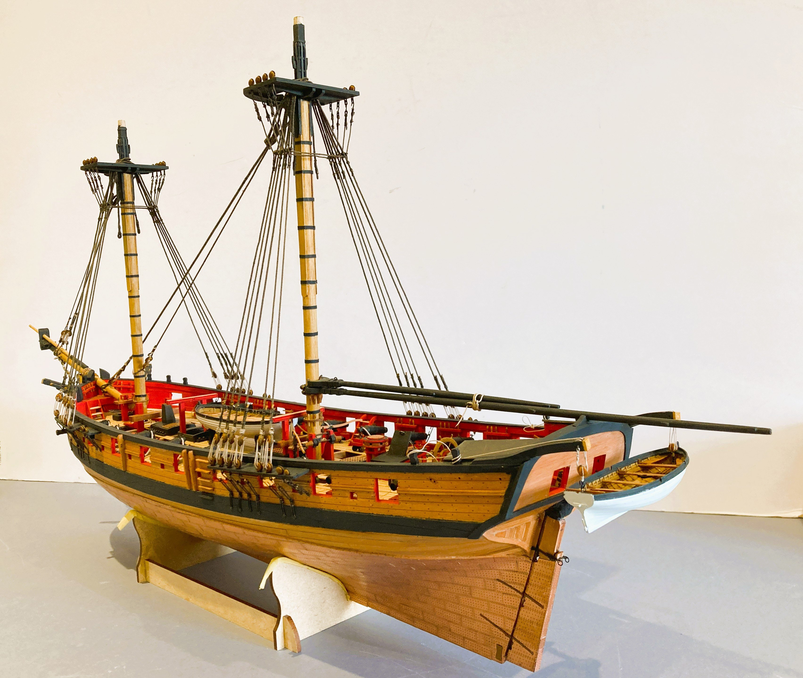
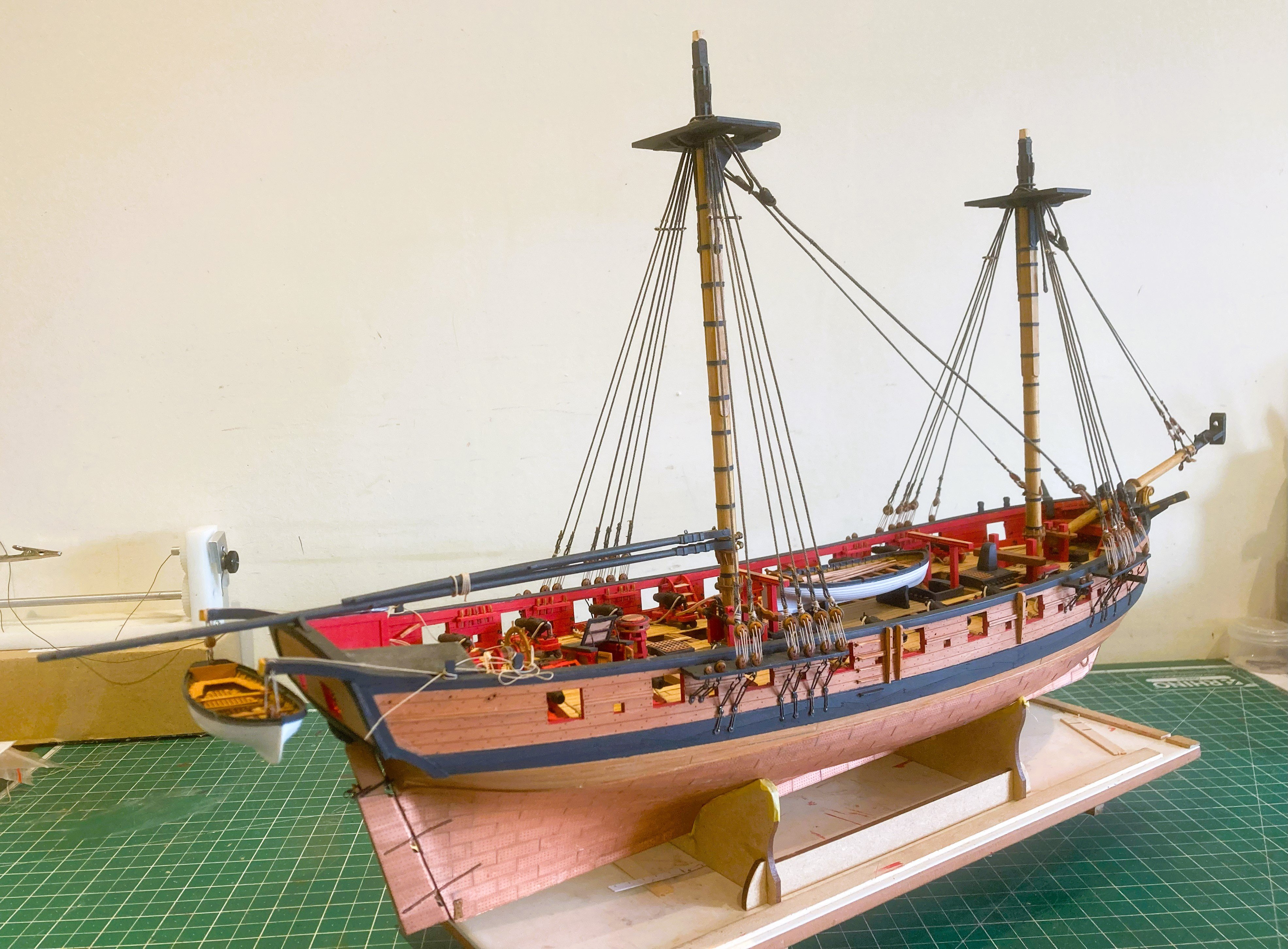
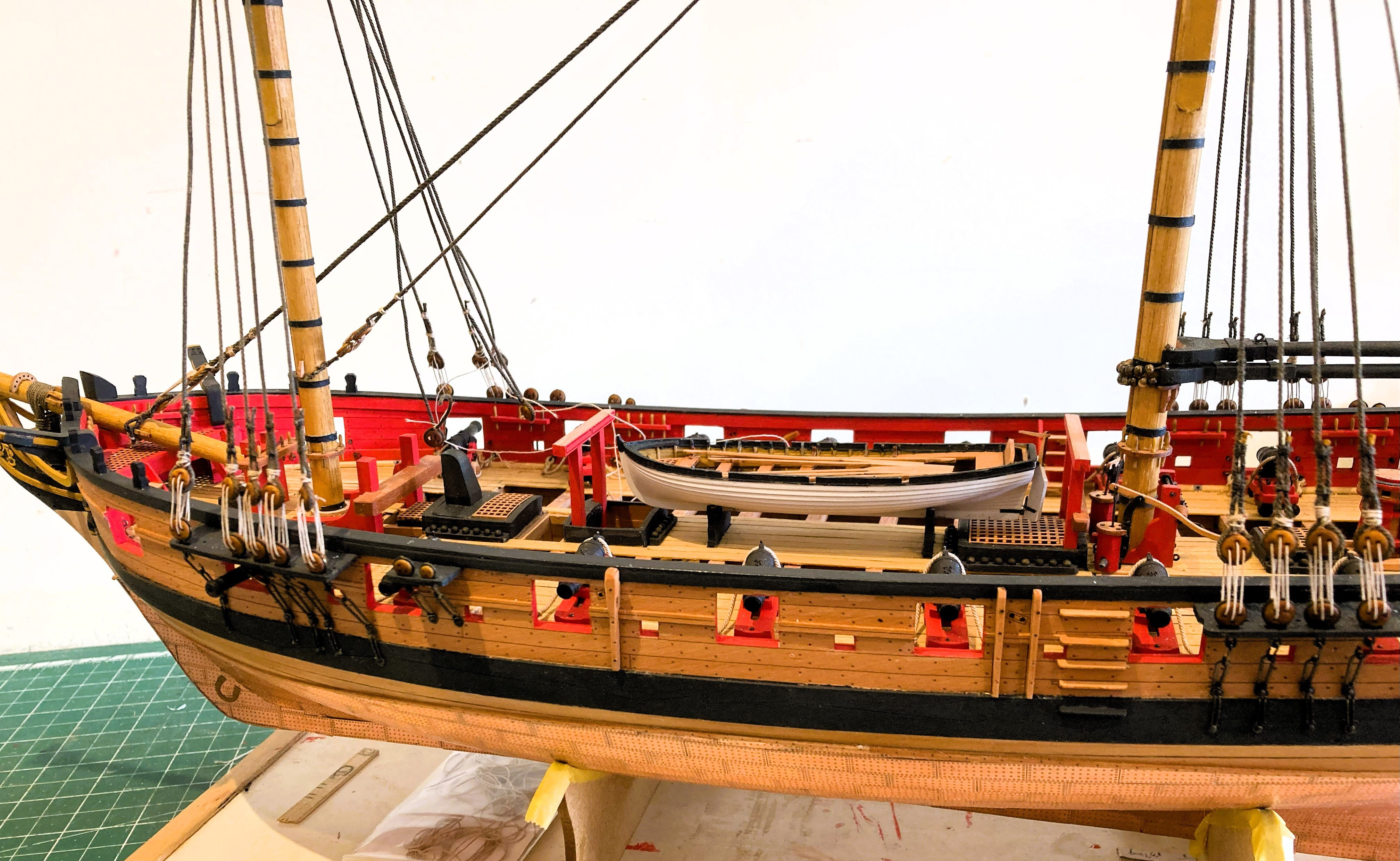
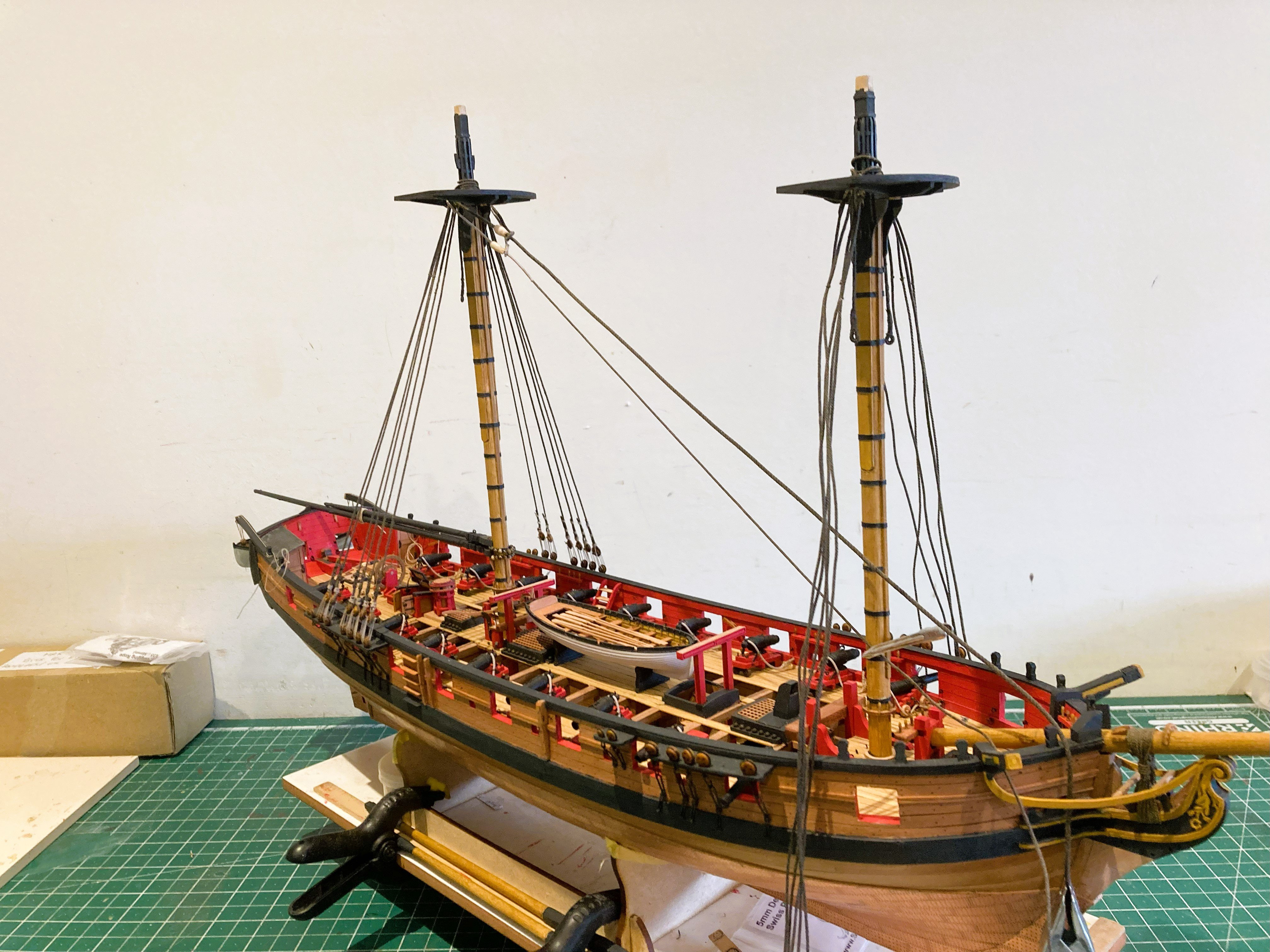
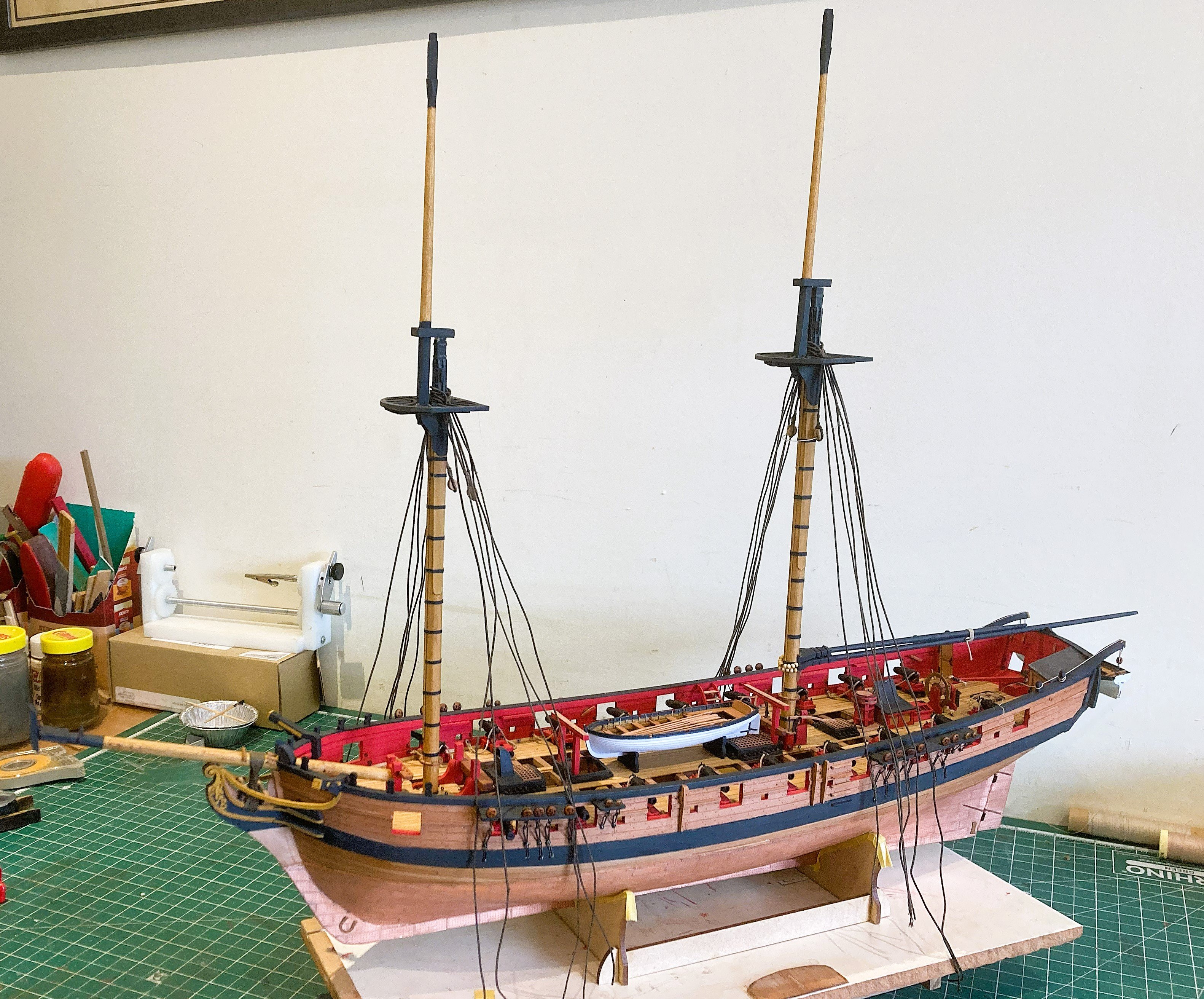
At this point I am attending to small additions and tweaks as the model nears completion.
5238a

5235a
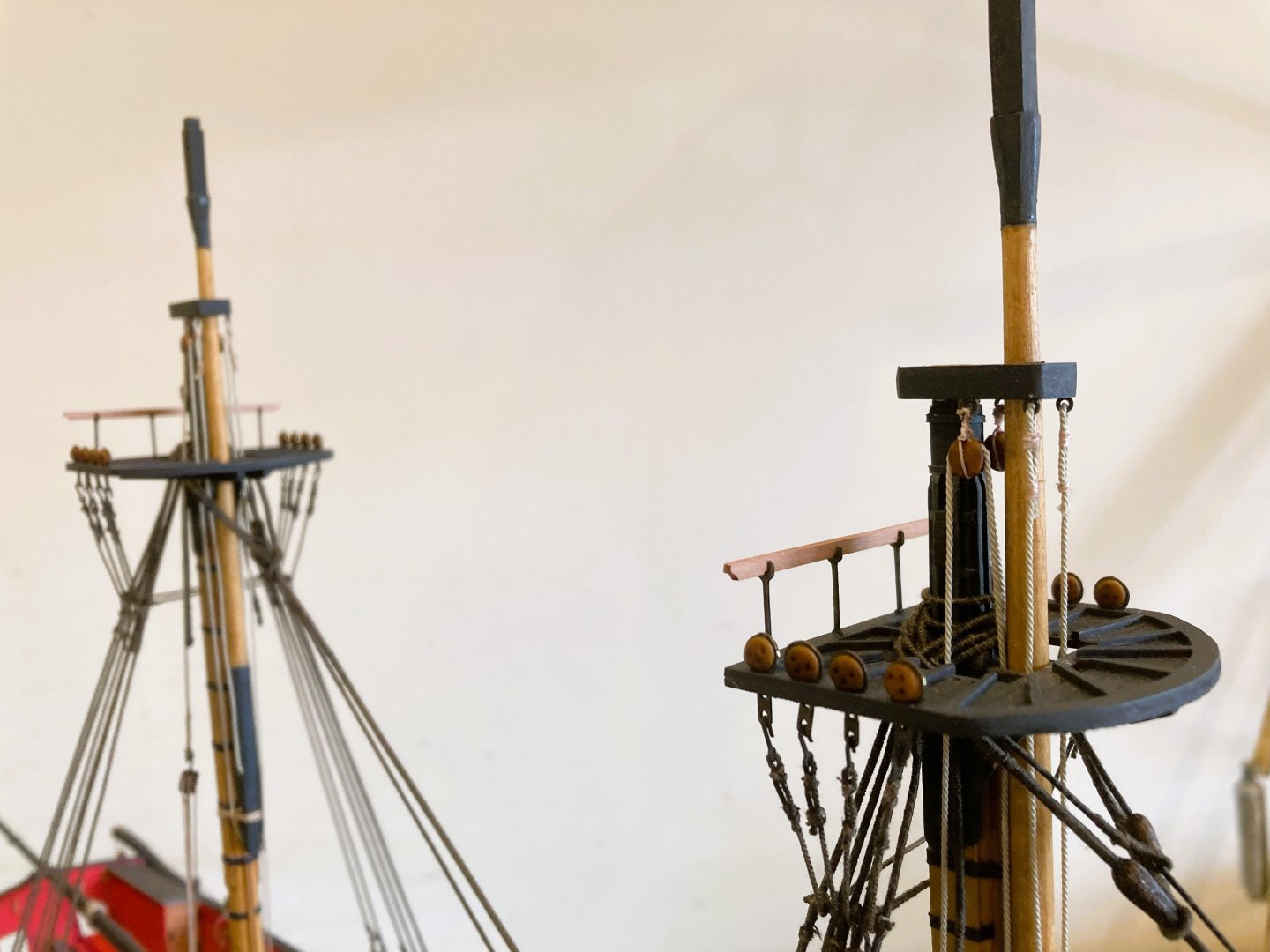
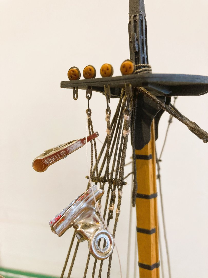
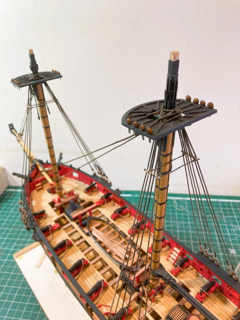
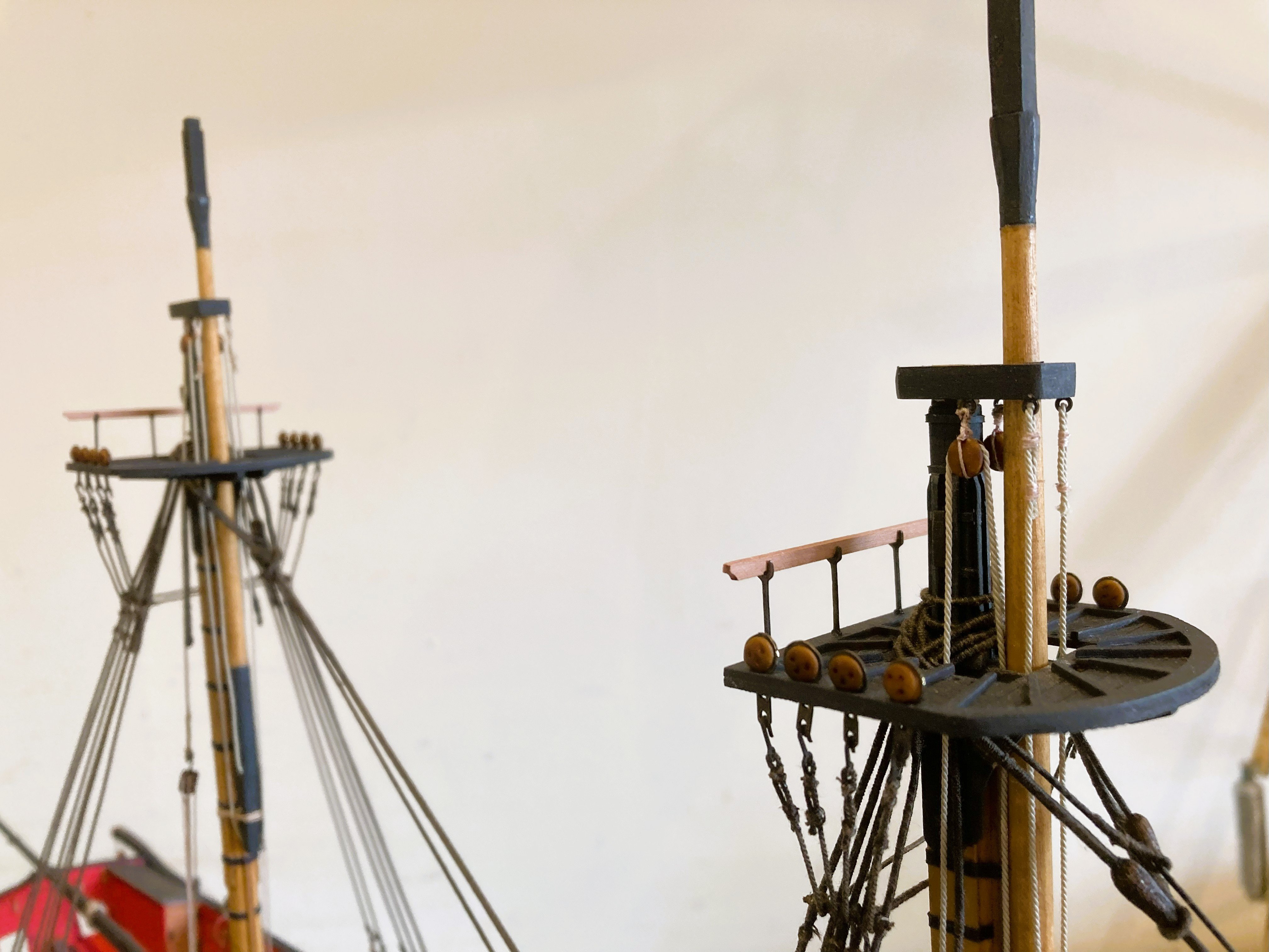
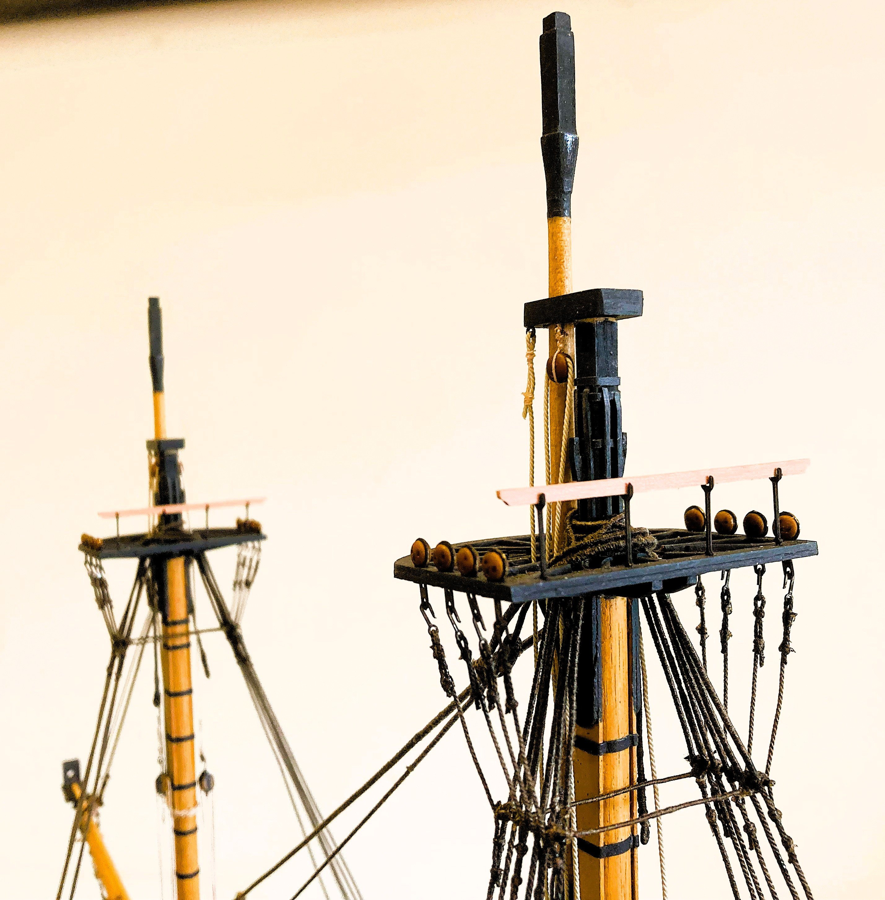
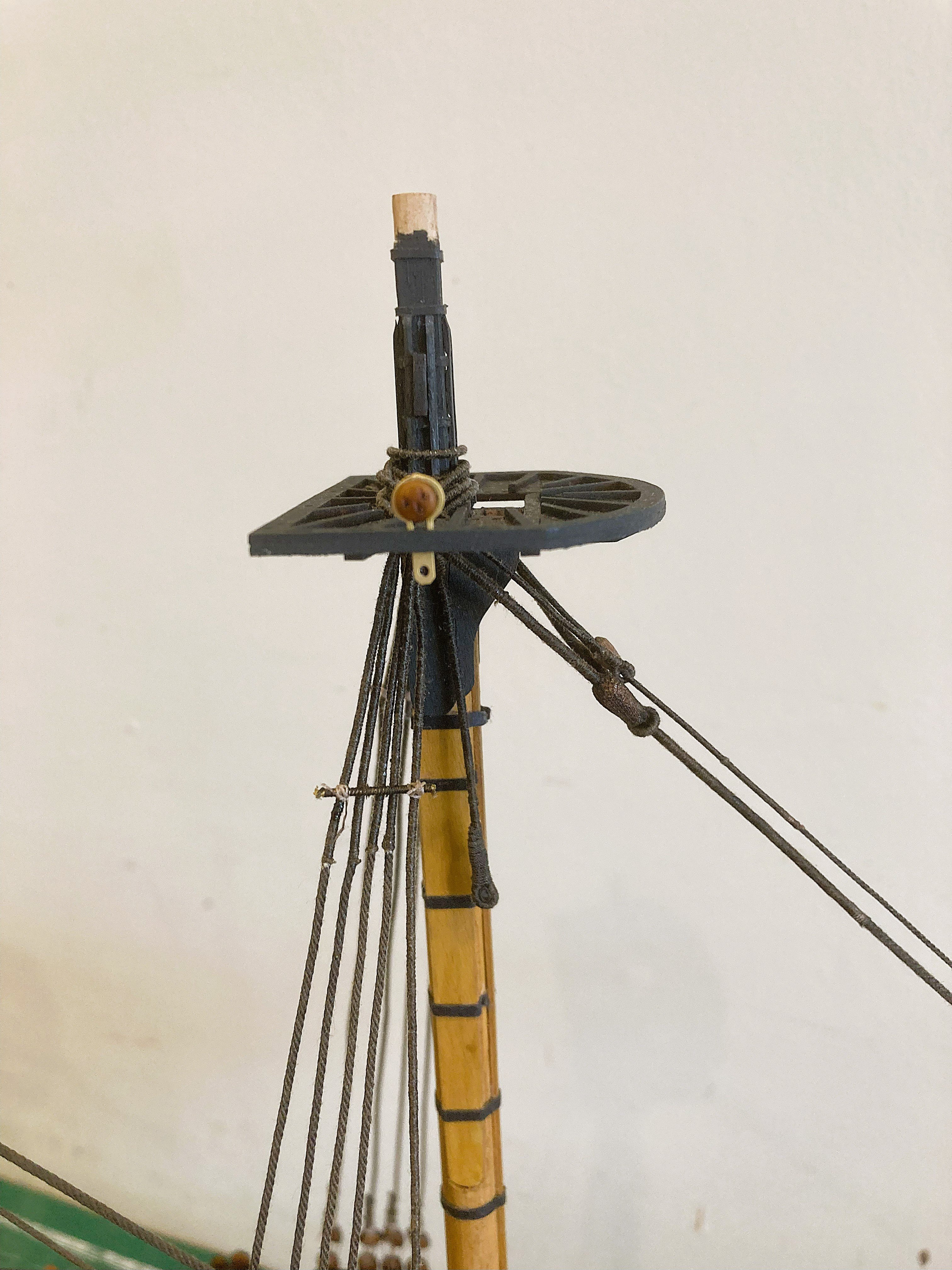
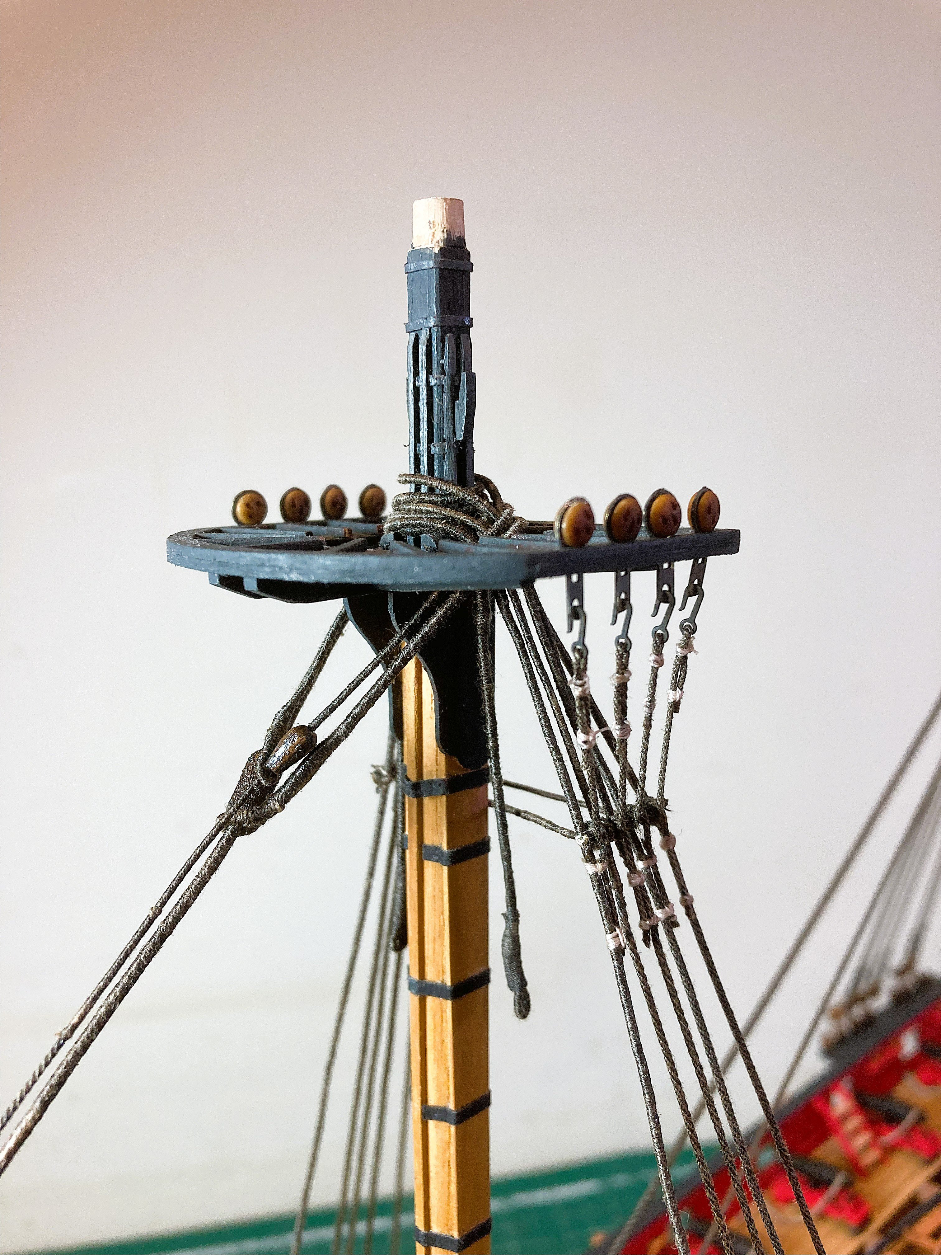
The stanchions and guard rails are added to the Mast tops, a perfect fit with nicely shaped rails in Pearwood.
5271b
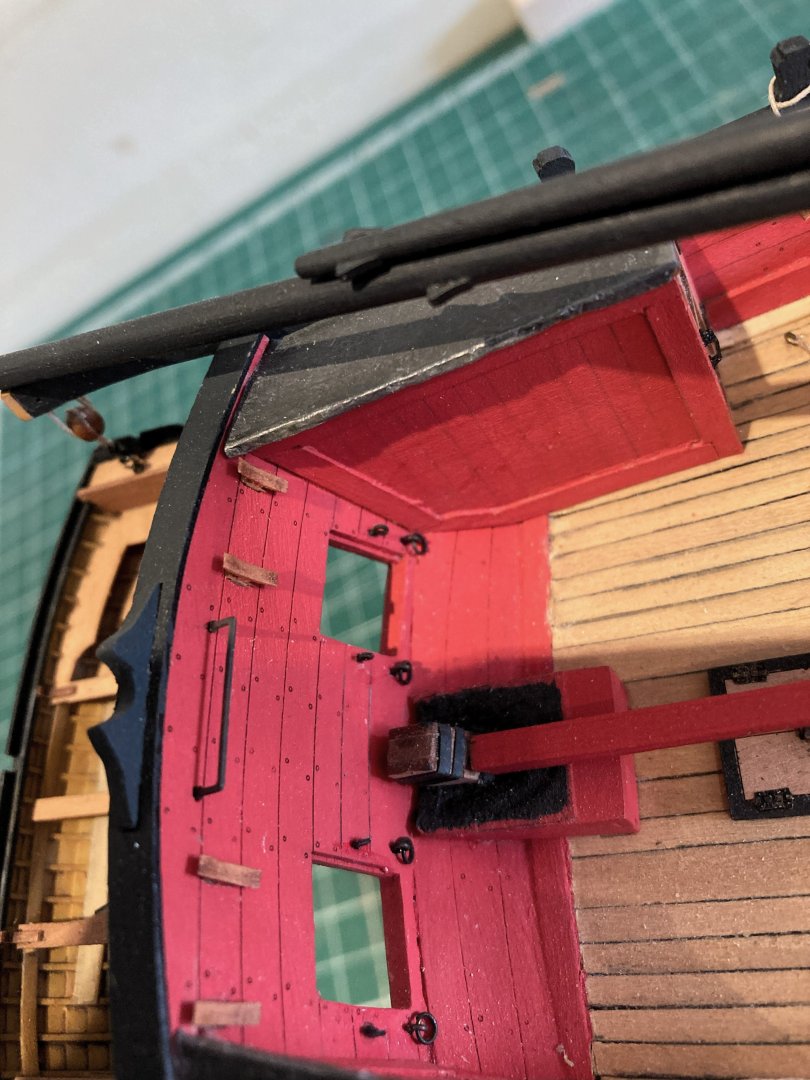
The Iron horse has been added to the transom.
I am still pondering whether to add limited rigging to the booms and fit the sheets.
5266a
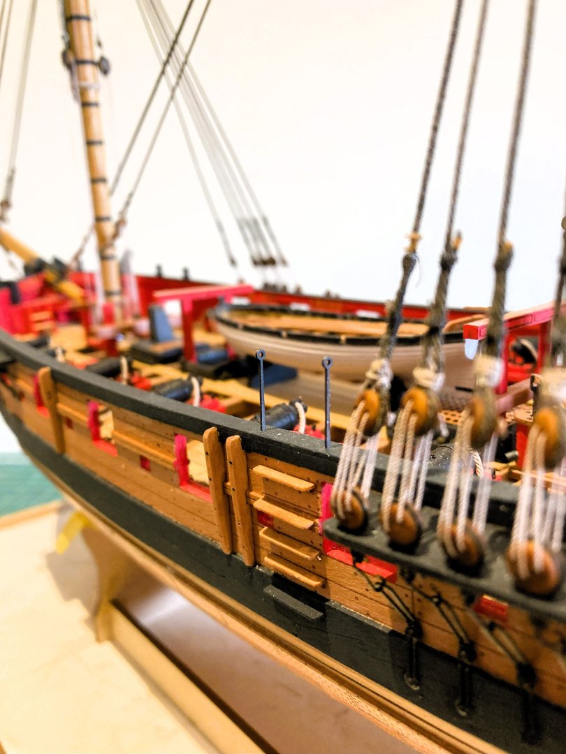
I added Entry steps stanchions, not sure if they were indicated on the plans, but I have a lot of these items in my spares box.
5277a
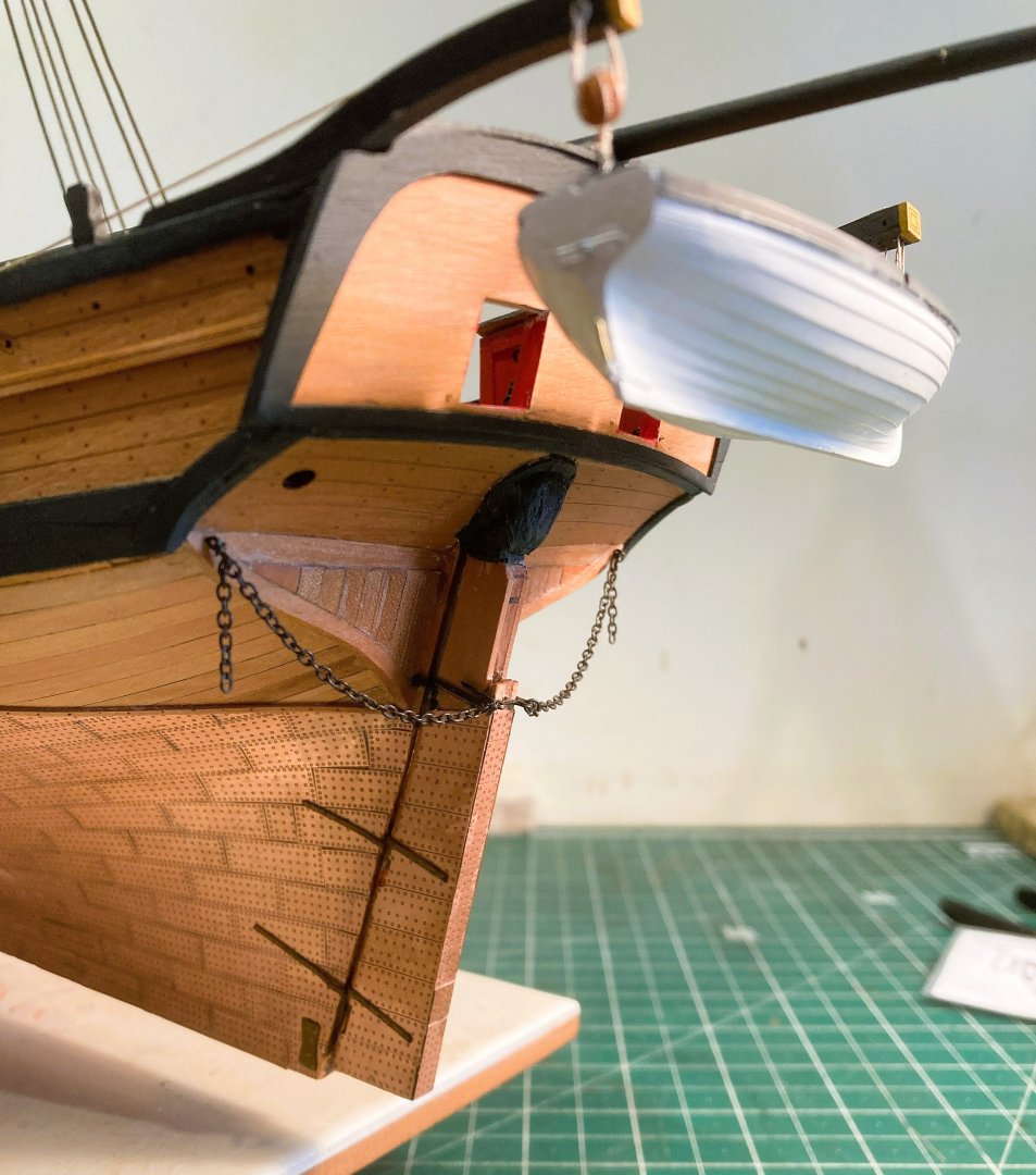
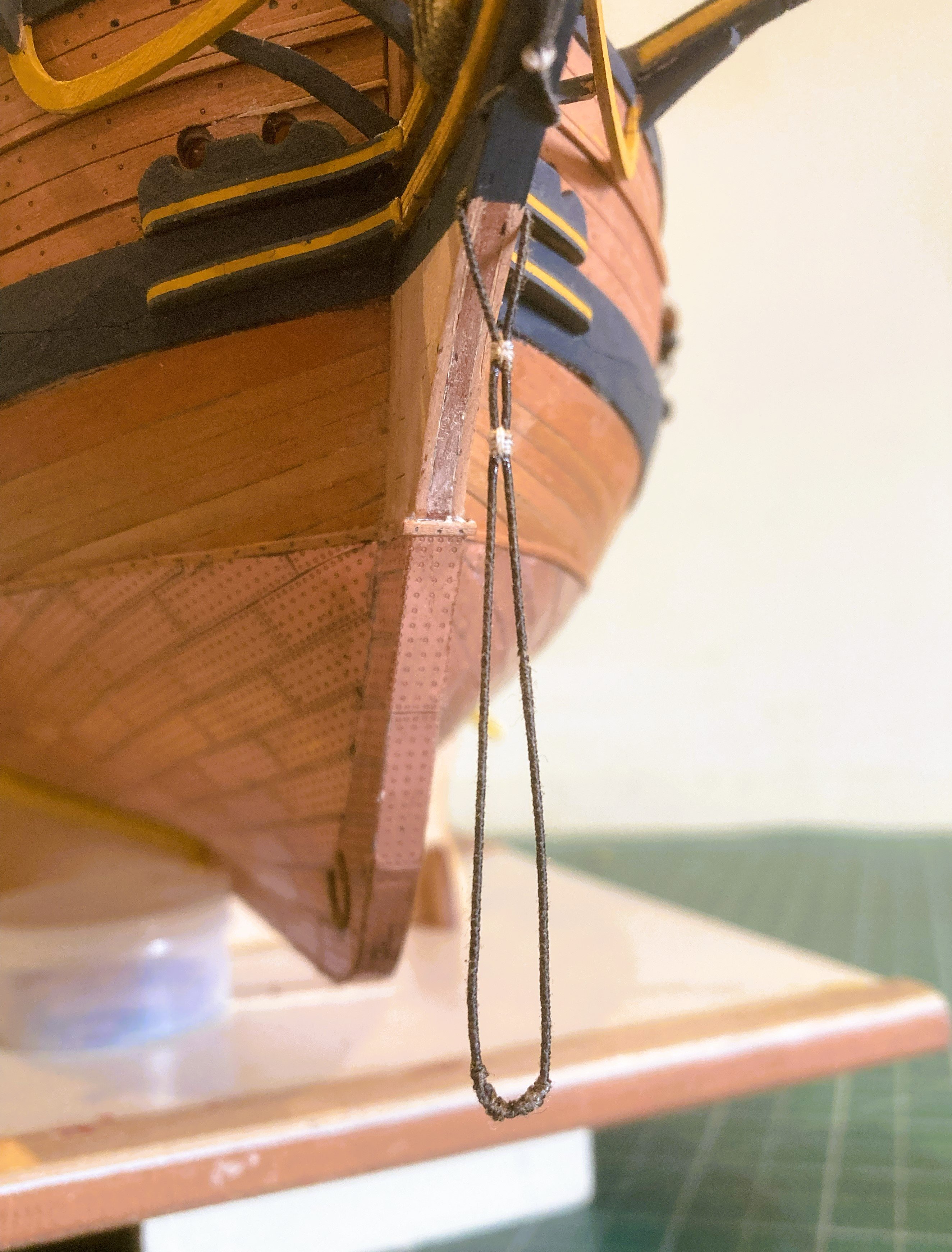
The Rudder chains are added but I have omitted the pendents.
The chains of 1mm size were in my chain stock.
5253a

5265a
5261a
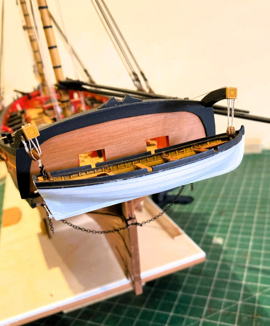
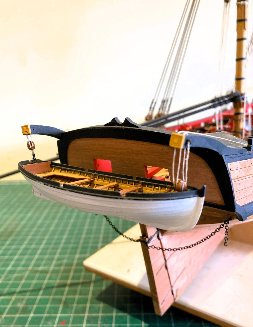
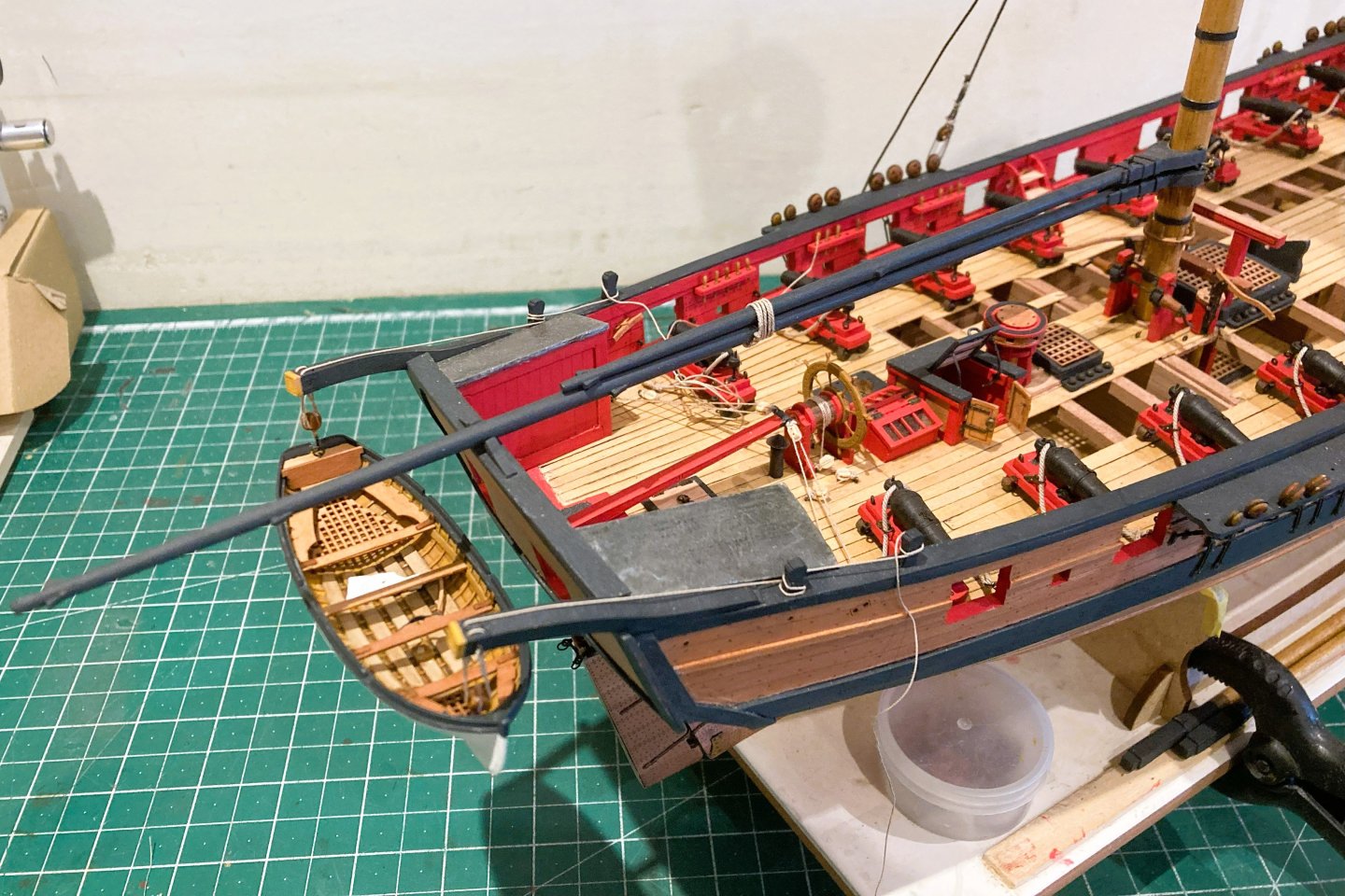
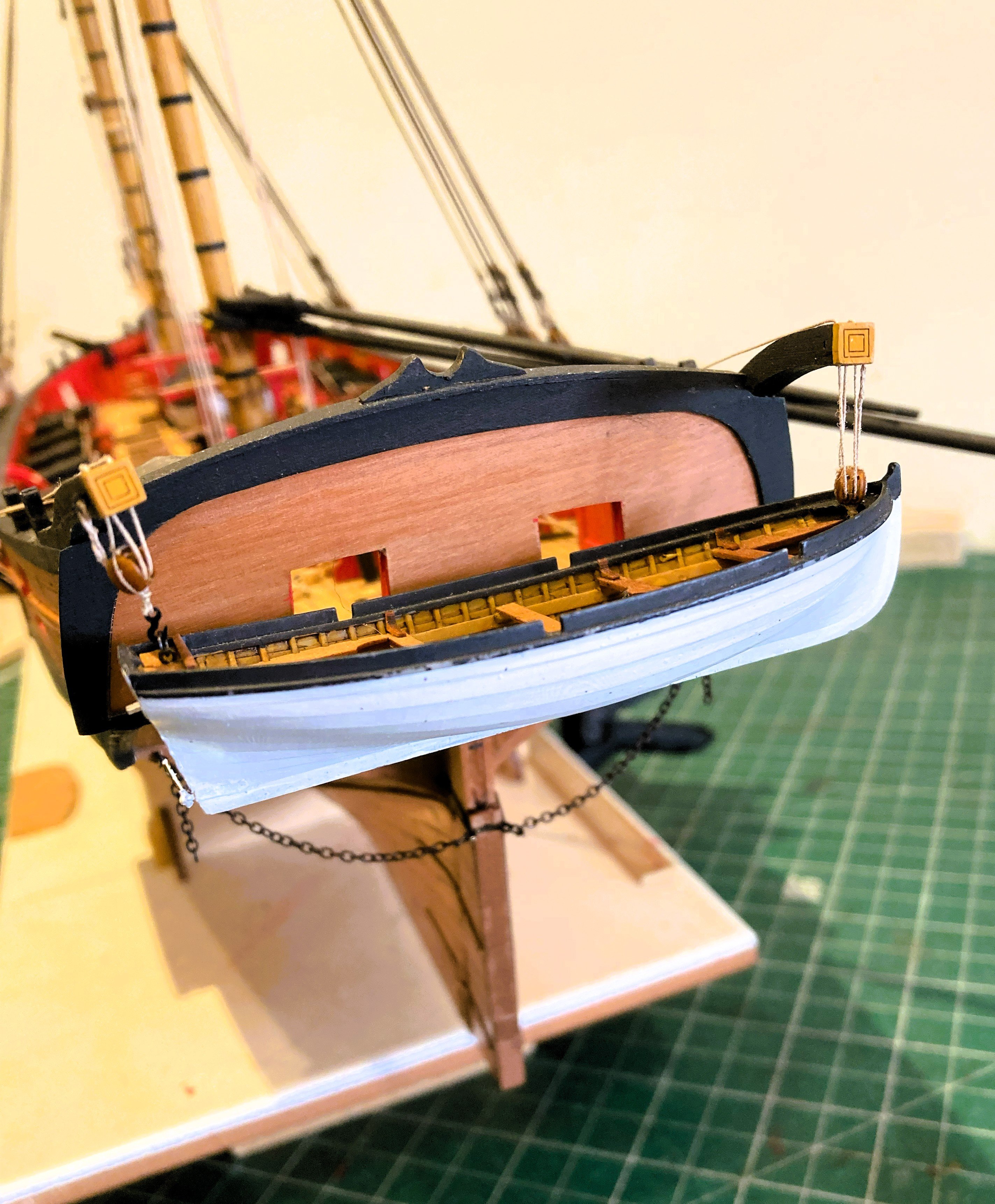
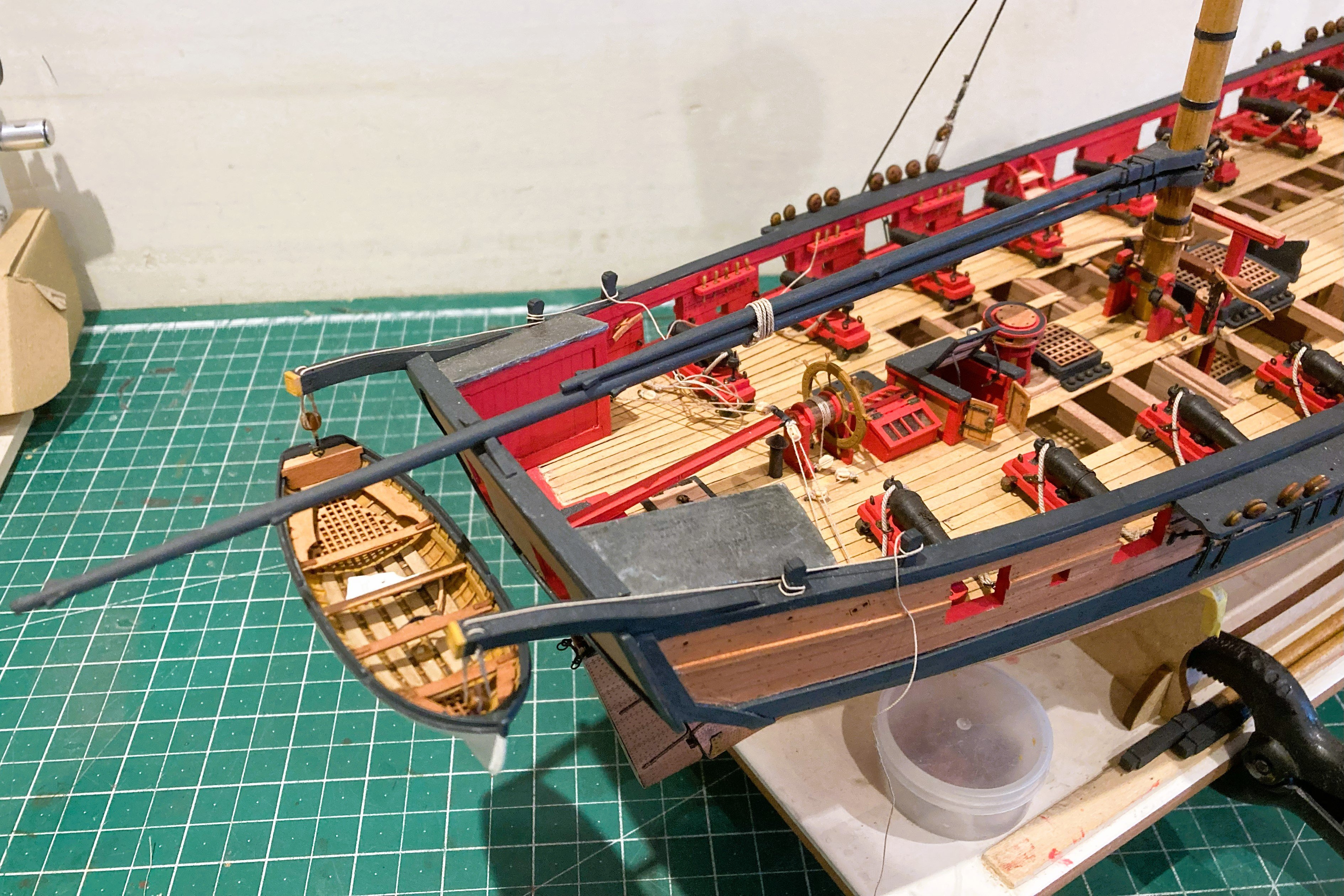
I had to re-visit the stern davit rigging which had become twisted. Attaching the boat is like working one of those Fairground crane grab machines, multiple goes, but at least success is obtained eventually.
5279a
5280a
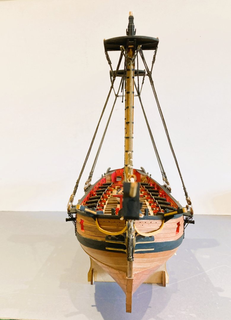
The one major job remaining is attaching the Ratlines, what deep joy.
B.E.
04/08/2025
- AON, Ryland Craze, Barbossa and 23 others
-
 26
26
-
-
Thank you, Alan,
I can’t reconcile the set-up either.
Such an arrangement seems more appropriate to smaller vessels where a windlass is used to raise the anchor and also act as the riding bitts.
075
This arrangement on my Pickle build makes more sense, altho’ I did puzzle about the use of Navel pipes in that era, but visually it worked for me.
Thanks for chipping in Richard, your Harpy is looking very good.👍
The photo’s indeed clearly show the problem, how is the cable to be handled in that short space. The large cable rising vertically thro’ a very small grating so close to the stove, just doesn’t sit right to my eye.
Using the Riding bitts does involve using the bitt post as well as the cross piece.
As you gain knowledge of the subject over the years it becomes harder to ignore apparent discrepancies but then find you can’t resolve them because of gaps in historical information.🙄
The Harpy set-up is a mystery to me, but I will dodge the issue by not fitting anchor cables. Were it fully decked I would have run the cables down thro’ the Main Hatch.
To keep things in perspective this is a minor fitting on the model that doesn’t detract from the overall appeal of Harpy.
I have made many changes to my kit for my own interest that the casual eye wouldn’t even notice.
I very much doubt that in many years ahead nautical historians will be poring over my model wondering why did he do that!
Regards,
B.E.
- hollowneck, Richard44, Thukydides and 7 others
-
9
-
 1
1
-
Post 103
Looking at the Anchors
The anchors in Resin are accurately detailed and are close to scale for a 20cwt anchor.
The stocks have very nice Pearwood facings detailing the strap positions, bolts and treenails.
For a ship the size of Harpy:-
Steel indicates three anchors at 20cwt, a stream at 7cwt, and a kedge at 3cwt 2 qtrs.
Anchor cables
A short length of 2mm ø line is supplied, sufficient for the kit arrangement.
The anchor cable circumference may be determined by the formula ½” of circ for every foot of the beam of the vessel.
In the case of Harpy with a beam of 28’ 1½” this works out at a 14” circ cable - 1.76mm ø line at scale.
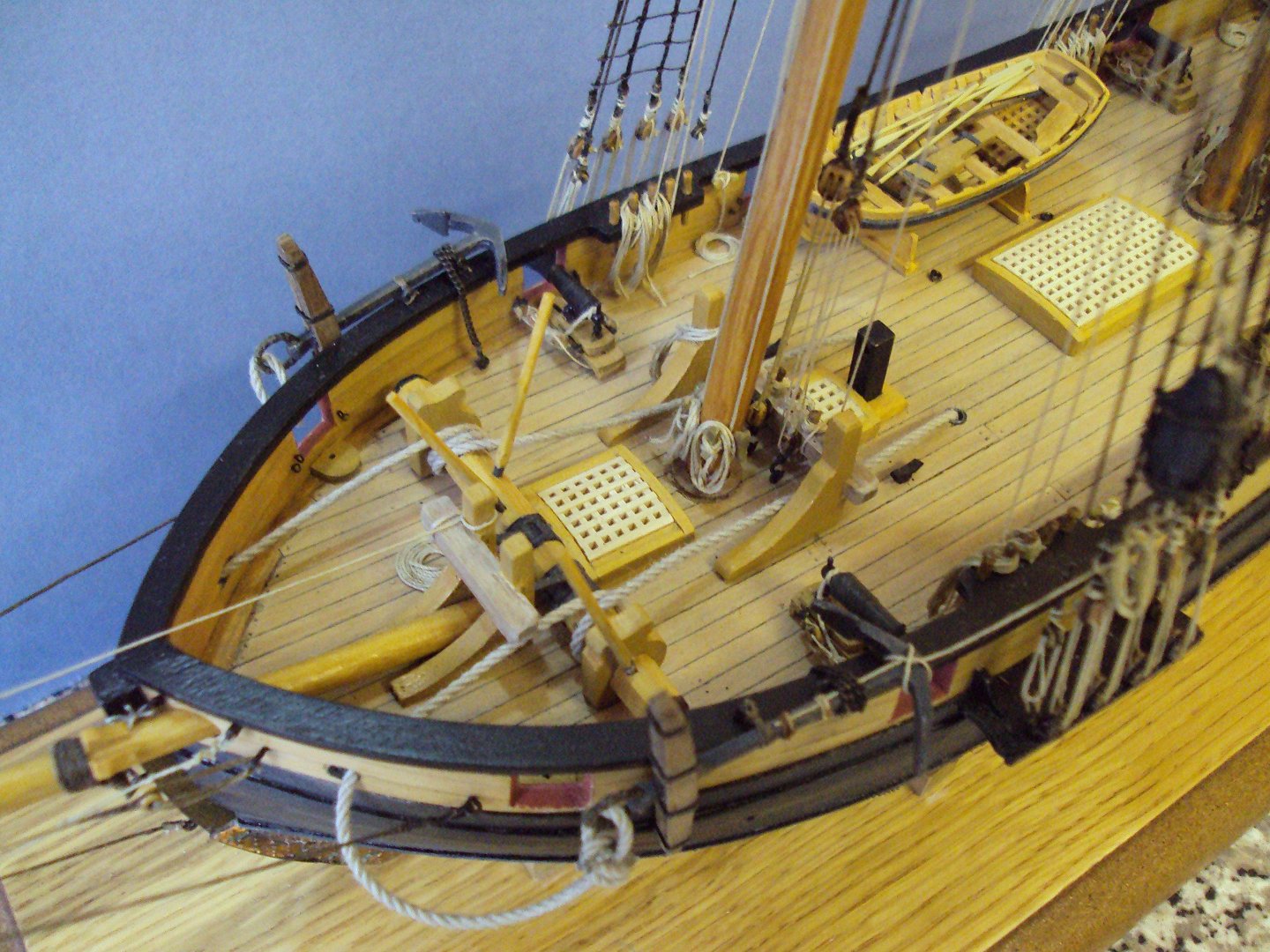
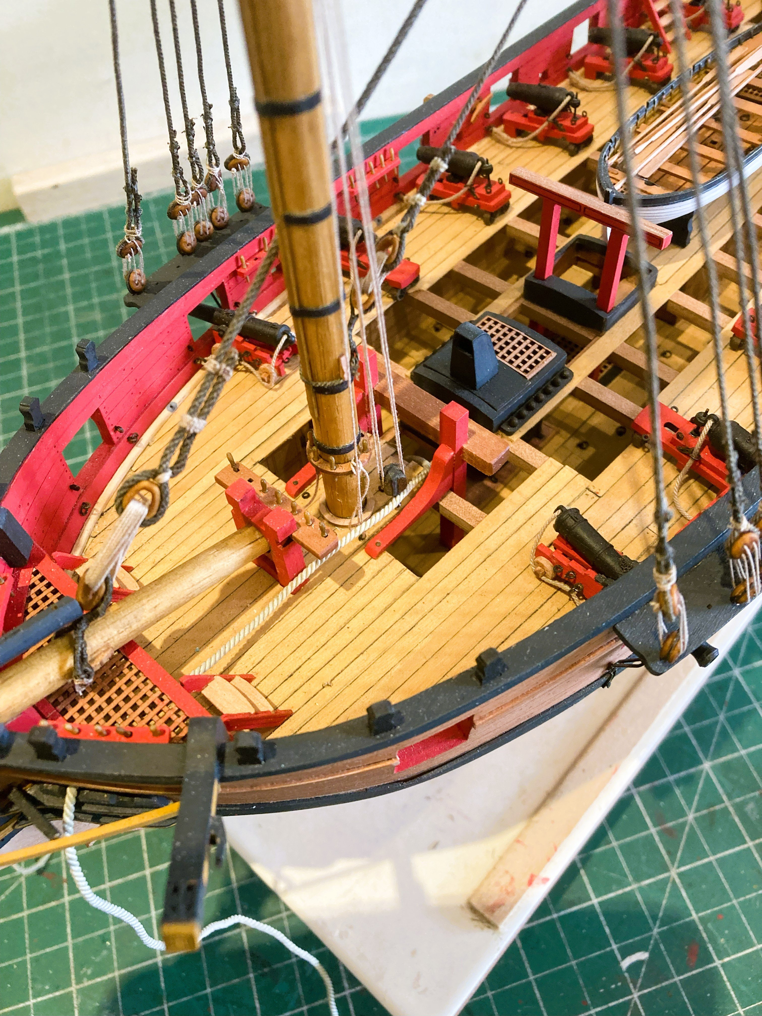
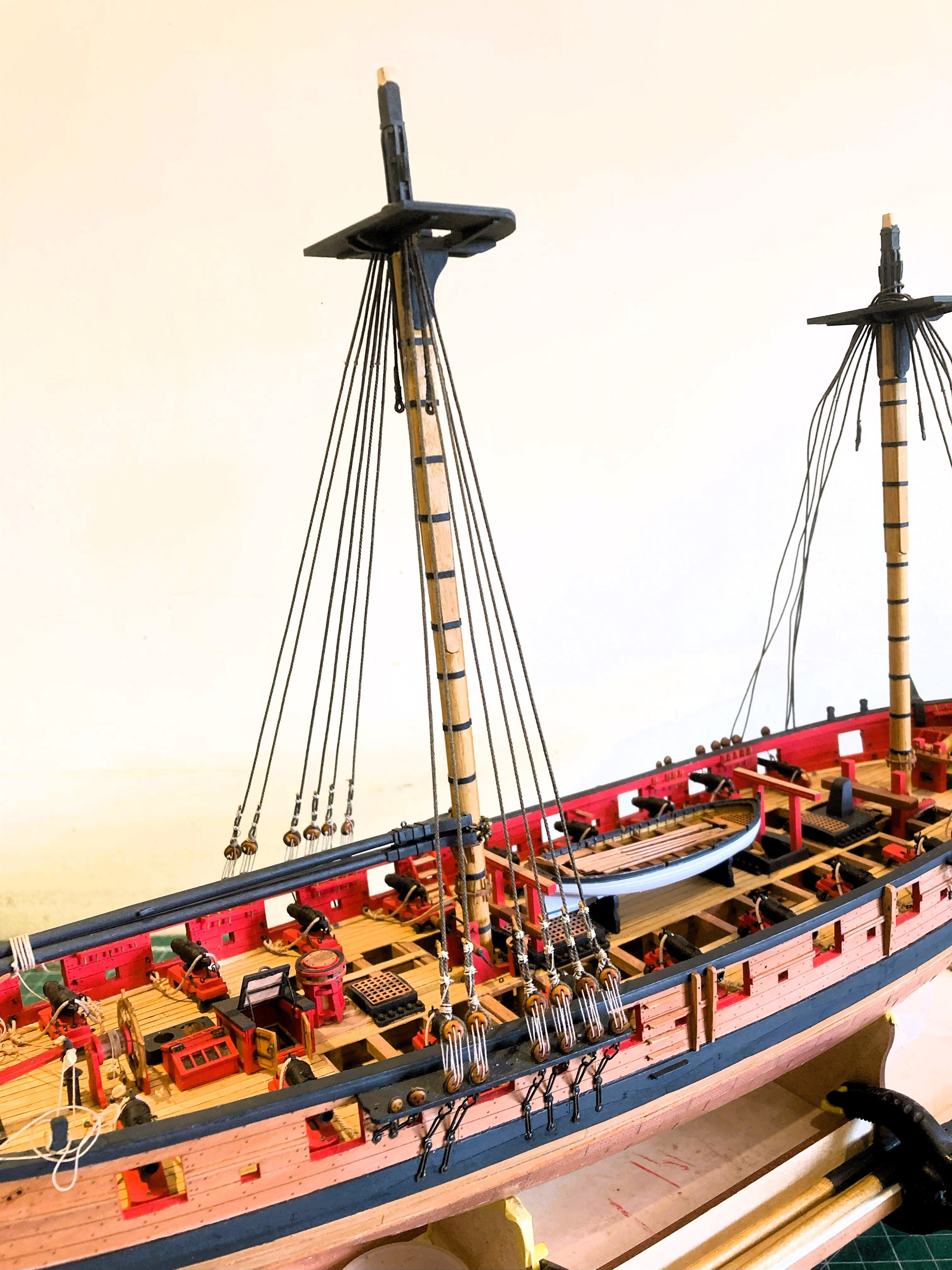
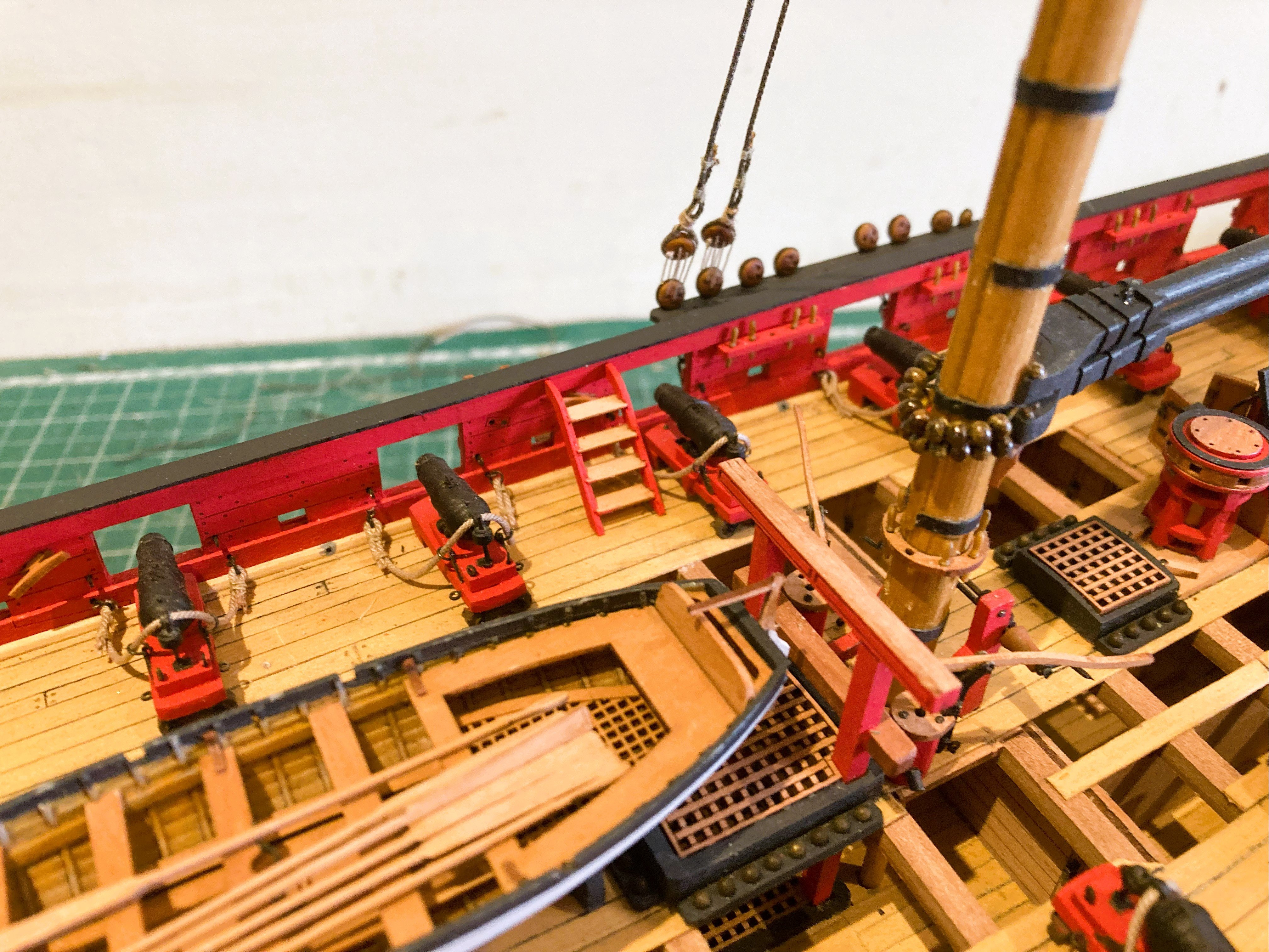
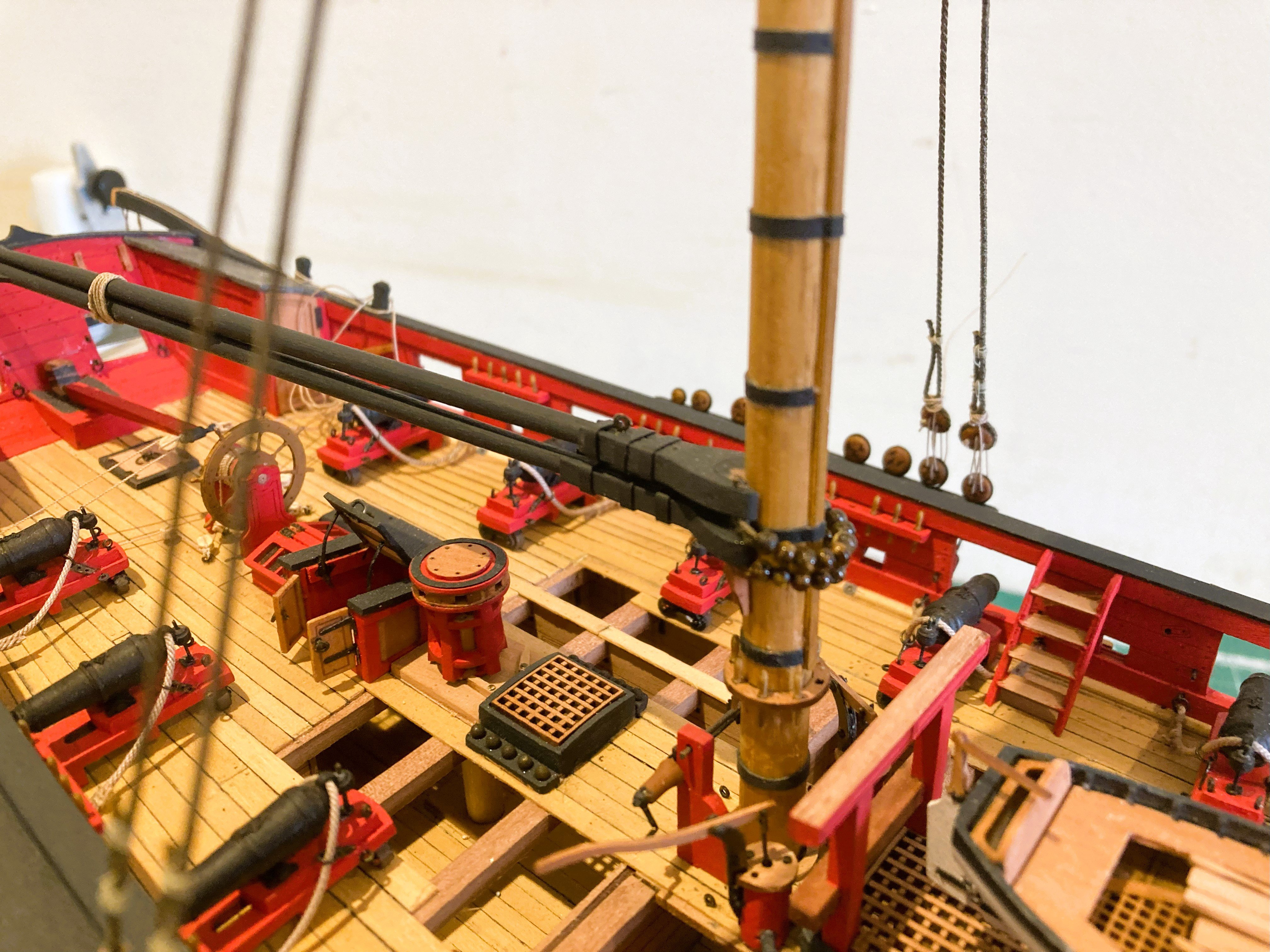
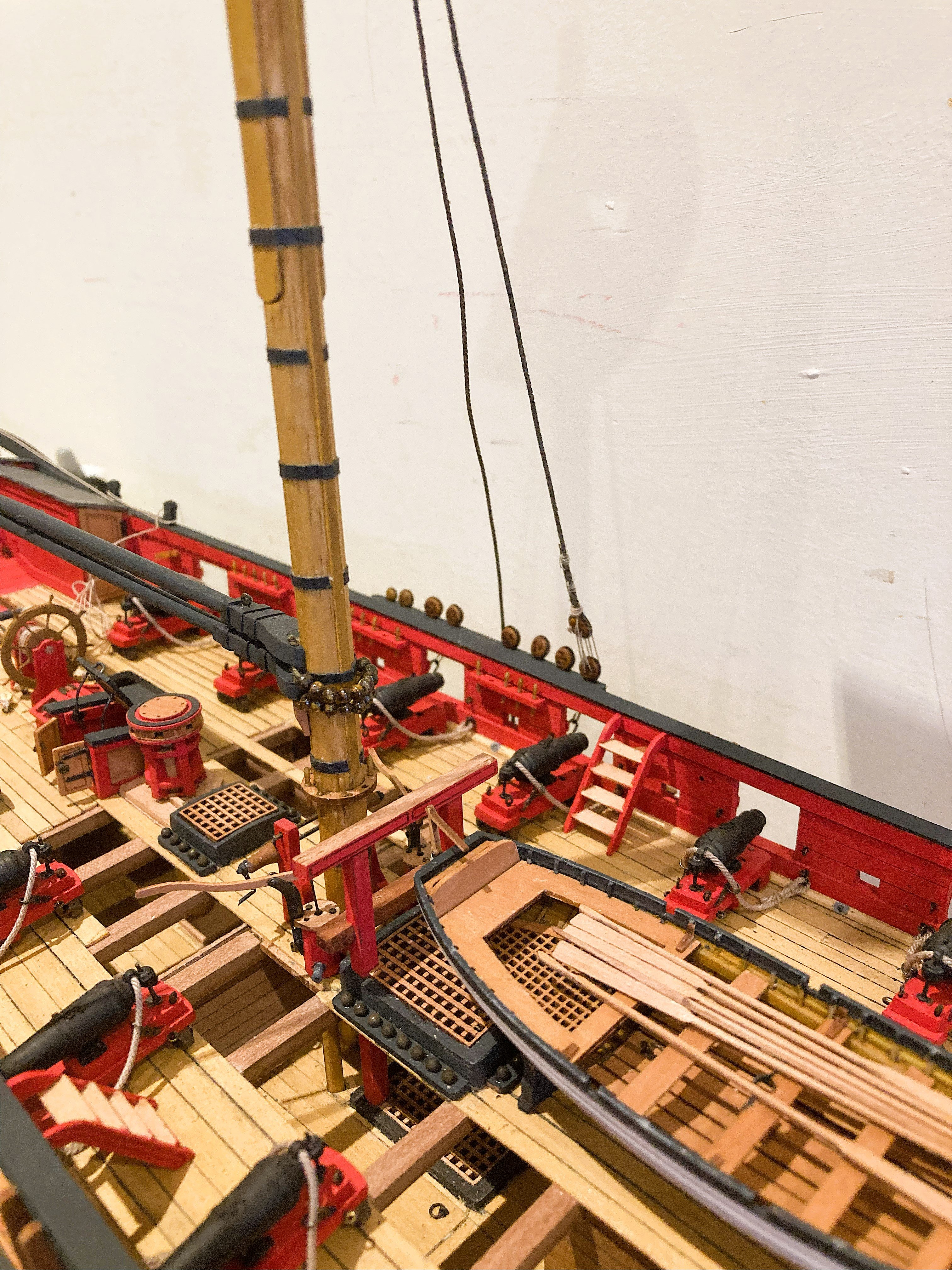
The business of anchors and cables are a puzzlement to me where Harpy is concerned.
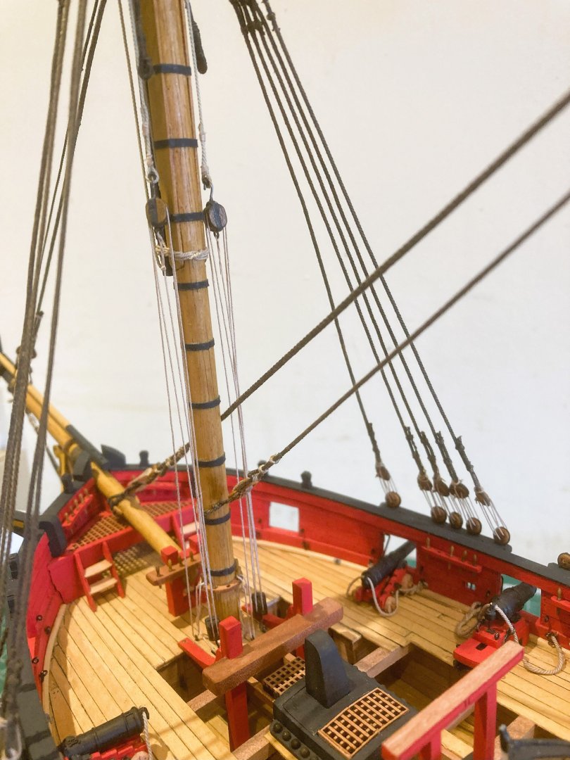
I have doubts about the kit set-up where the large cables are shown feeding thro’ a small grating just above and forward of the Galley stove above the open hearth.
I think this is a steam grating for the stove and a fair run of these heavy and often wet cables would appear to be impeded by this arrangement.

5205a
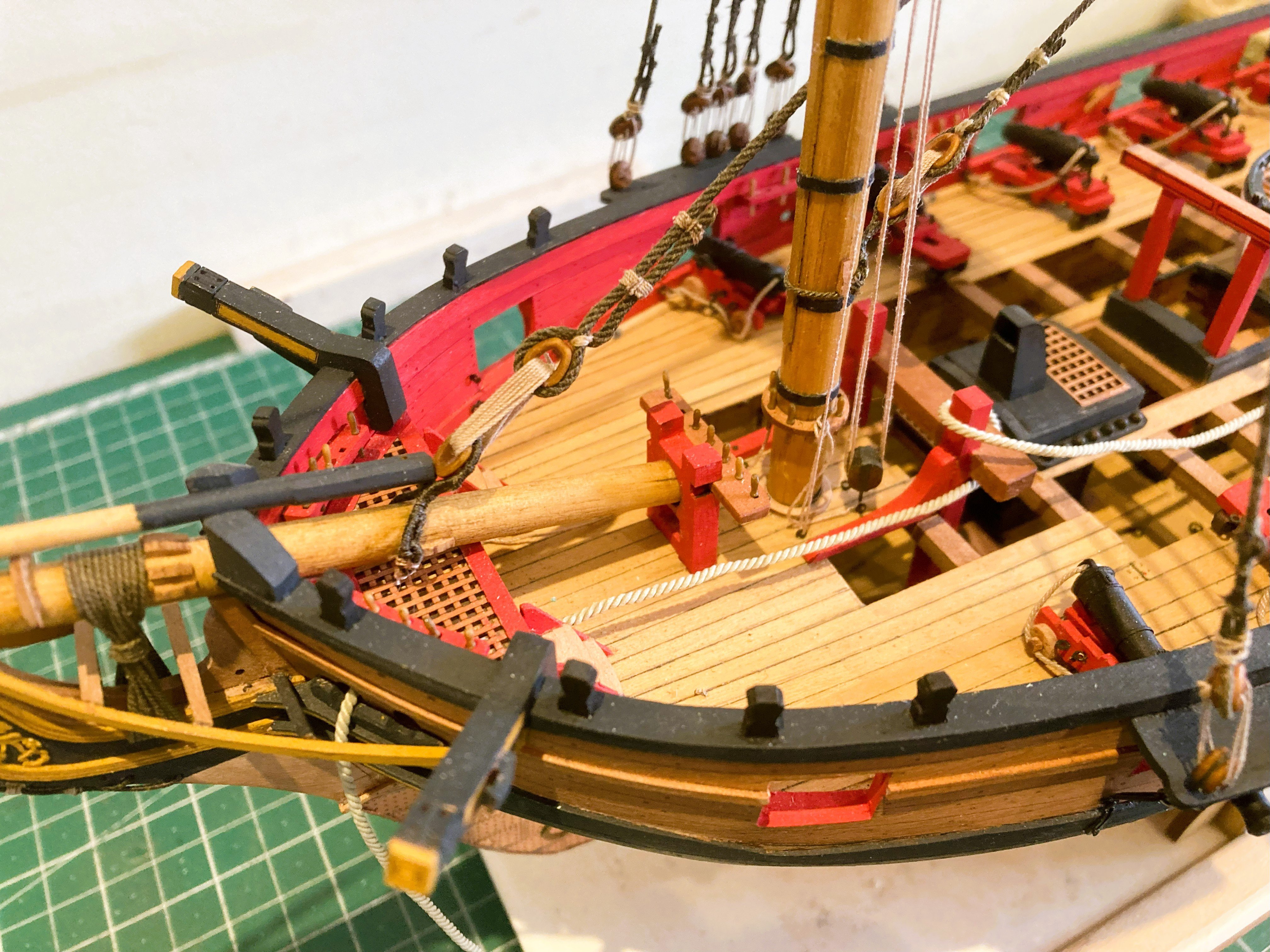
The cables with the kit arrangement would exit the lower deck almost vertically to the Riding Bitts in a position that would involve tight bends of the cable if the Riding Bitts are used for their purpose. The run of the cables also risk fouling the rigging connection points around the partners of the Foremast.
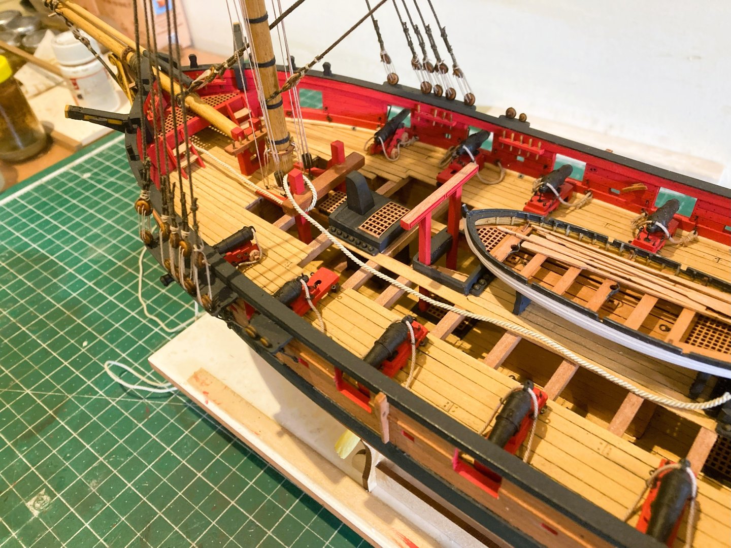
5203a
My view is that the cables would run to the Main hatch as was the usual practice.

5204a
With this arrangement stoppers could be used to take the strain whilst at anchor.
I usually like to display anchors with the cables secured to the Riding bitts but there are issues that preclude this with Harpy.
On a fully decked model this would not be a problem as the cables would run below decks unseen. With Harpy the lower deck is on view so simply feeding the cables down the main Hatch with a short loose end is not an option.
It is difficult to imagine how an anchor cable with a scale length of 120 fathoms would even fit on the Harpy model.
We know from the Adm. plan the location of the cable storage compartments running either side of the ship on the Lower deck.
These are nicely depicted on the model, but as with the Adm. plans there is no indication how the compartments were accessed to stow the cables.
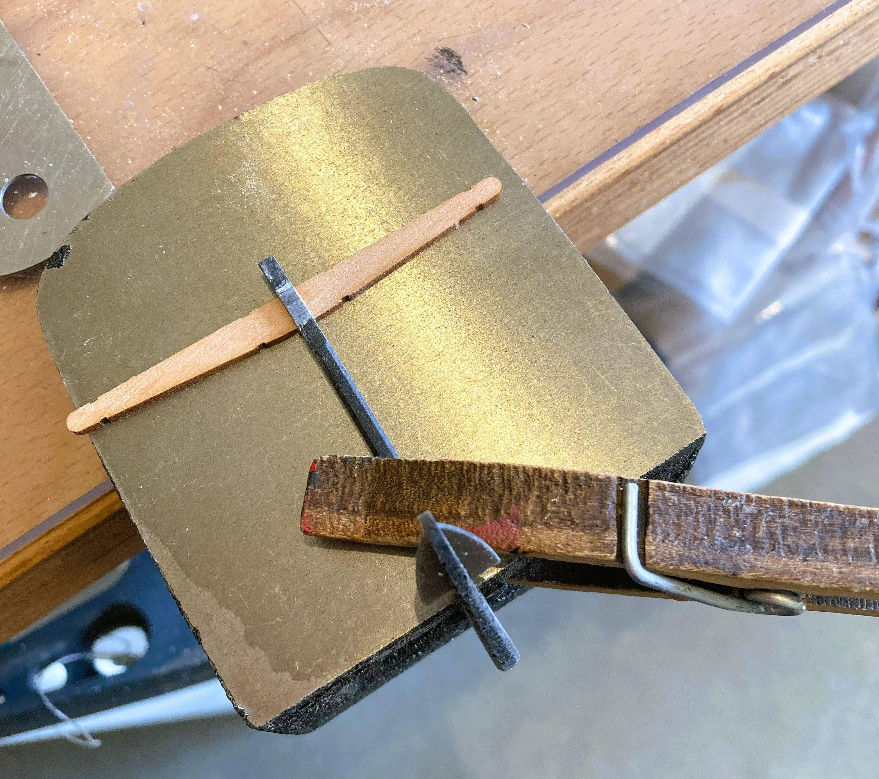
Assembly of the Anchors
The anchor stocks are correctly formed in two halves fitted either side of the shank. I found it necessary to broaden and deepen the slots on the stocks and also file down the resin shank so that the stocks fitted together allowing for a narrow gap between them adjacent to the shank.

5207a
I assembled the stocks and shanks before adding the facing pieces. A slight taper was formed toward the stock ends.

5216a
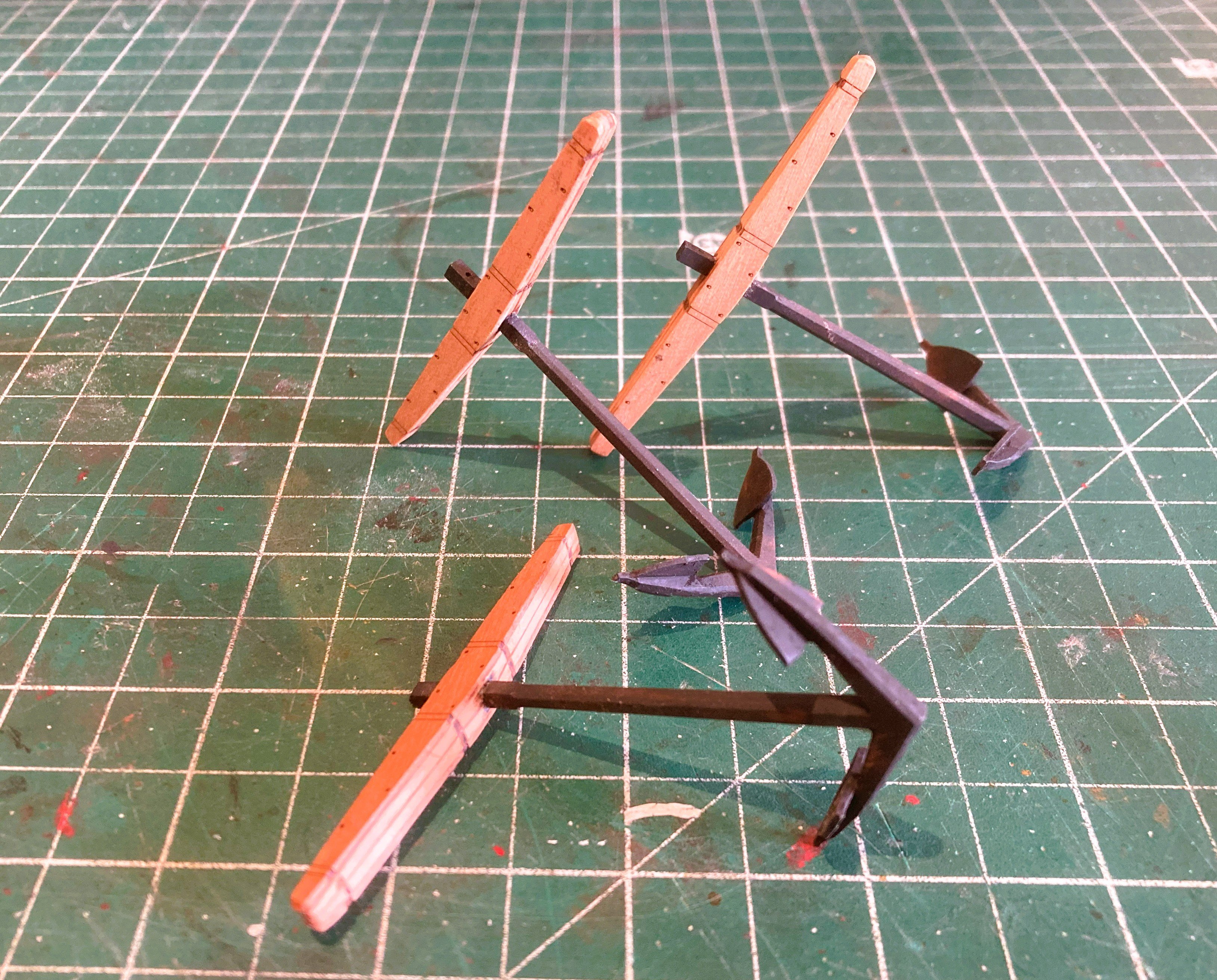
I used Vallejo Black/grey to paint the anchors followed by use of Dark Brown and Rust weathering powders.

5219a
The iron bands are represented by Heat shrink tubing on the model.

5220a
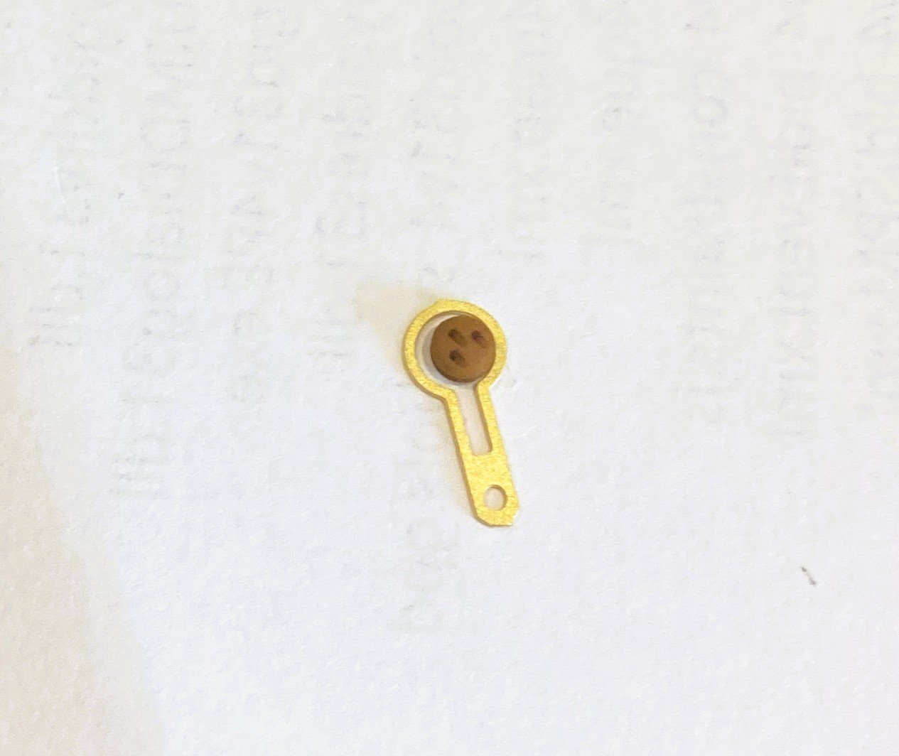
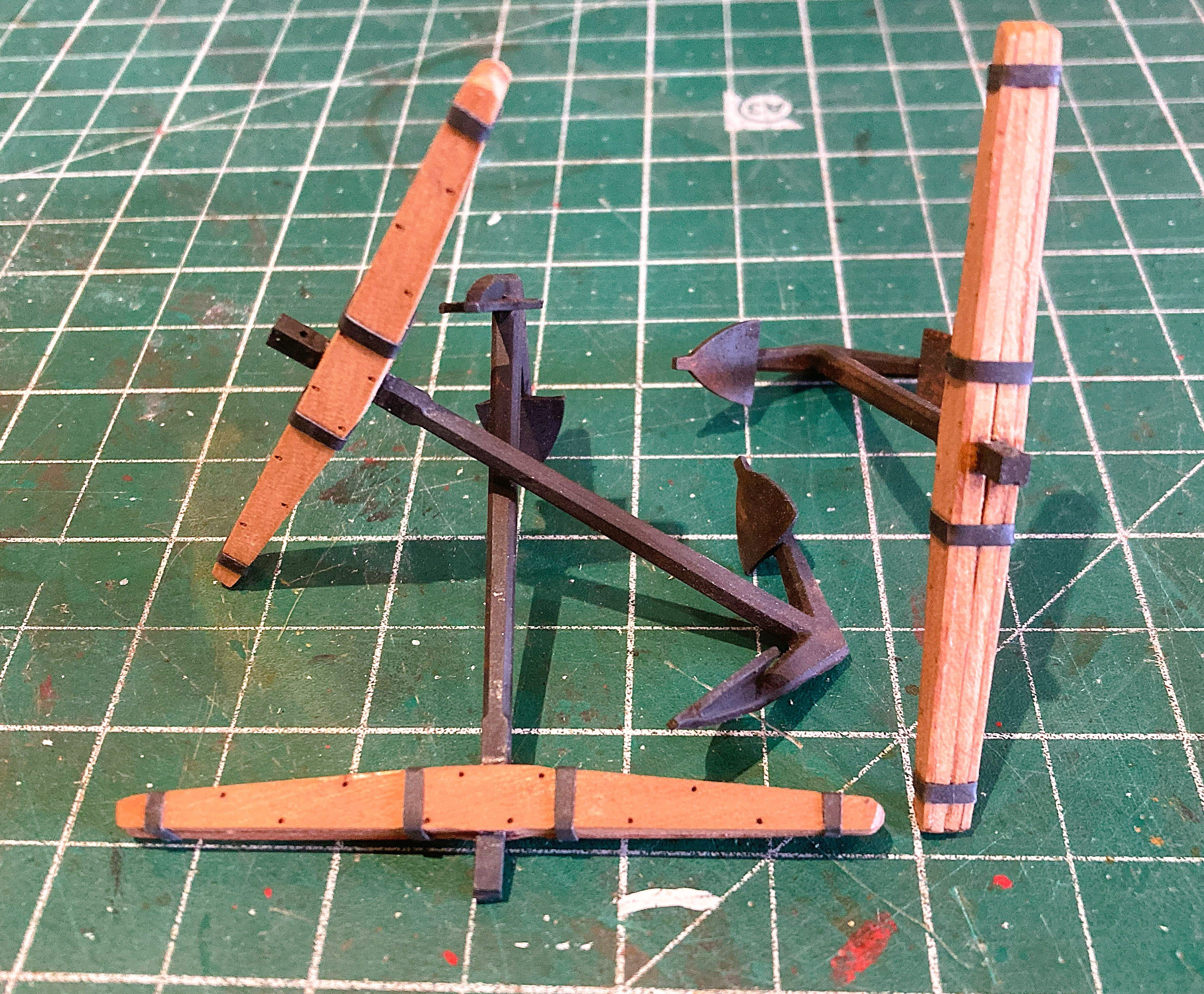
The Anchor rings are provided in etched pe.
I replaced these using 1mm brass wire with an outer diameter of 8mm. For the Puddening I used 0.30mm line.
5223a
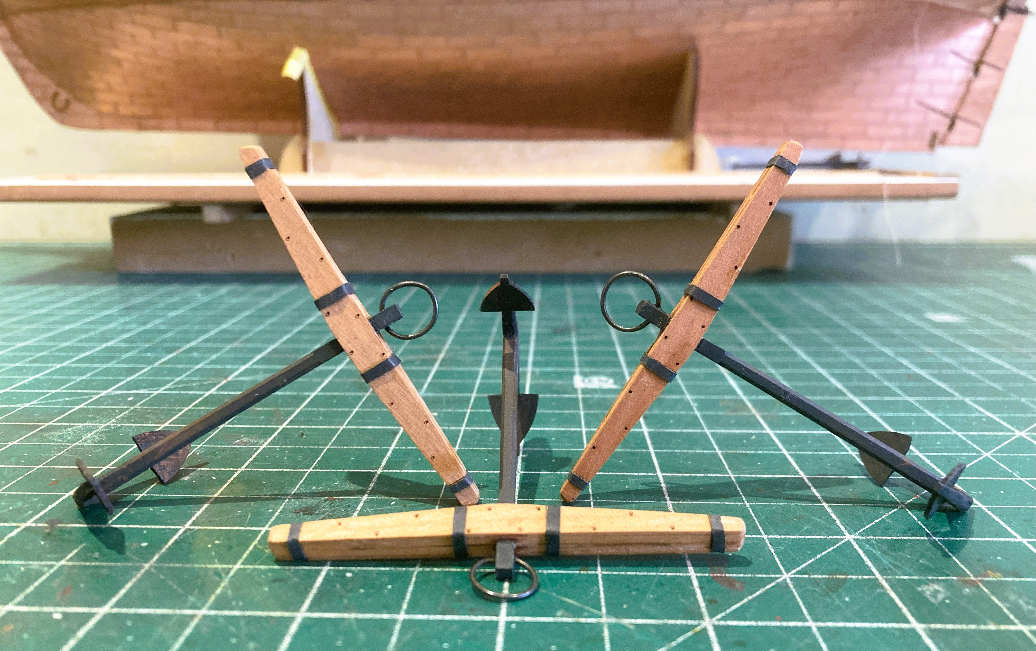
Applying the puddening can be a bit of a faff unless the Anchor ring can be held secure during the process.
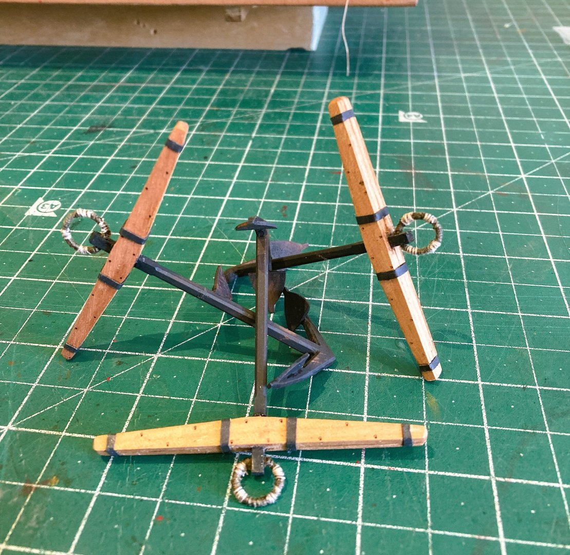
5231
The anchors are now completed, and I’ll decide on the display later.
B.E.
02/08/2025
-
Hi Ronald, the gap does look a little wide to my eye.
I didn't use the kit set-up on my build of Sphinx, I opted for a working version of gudgeons and pintles and tweaked the set up until my eye was satisfied.
On Indefatigable I did use the kit simplified version but they look a little closer than on your photo.
Could you perhaps countersink the holes on the stern post to allow the gudgeon to sit further in?
B.E.
-
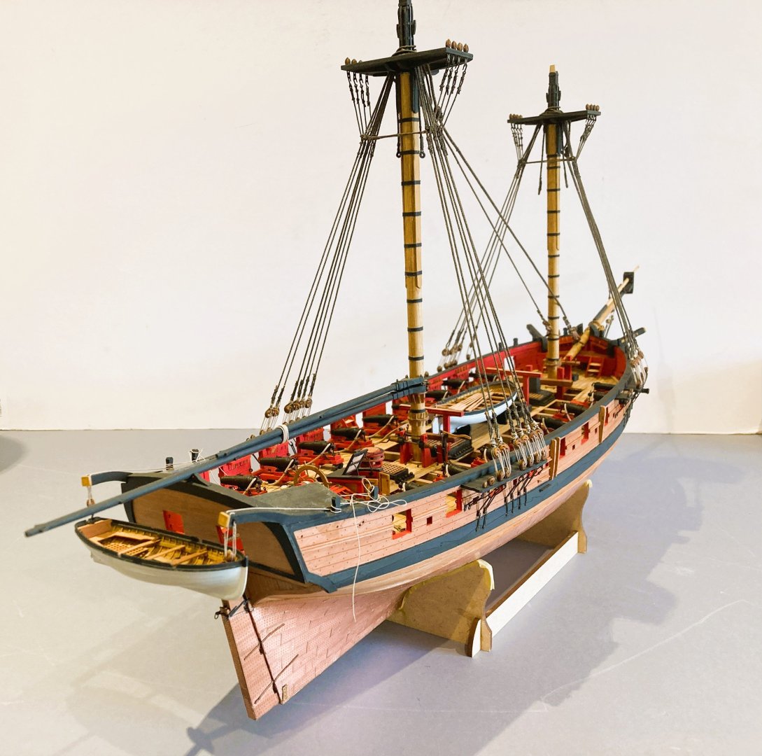
Post 102
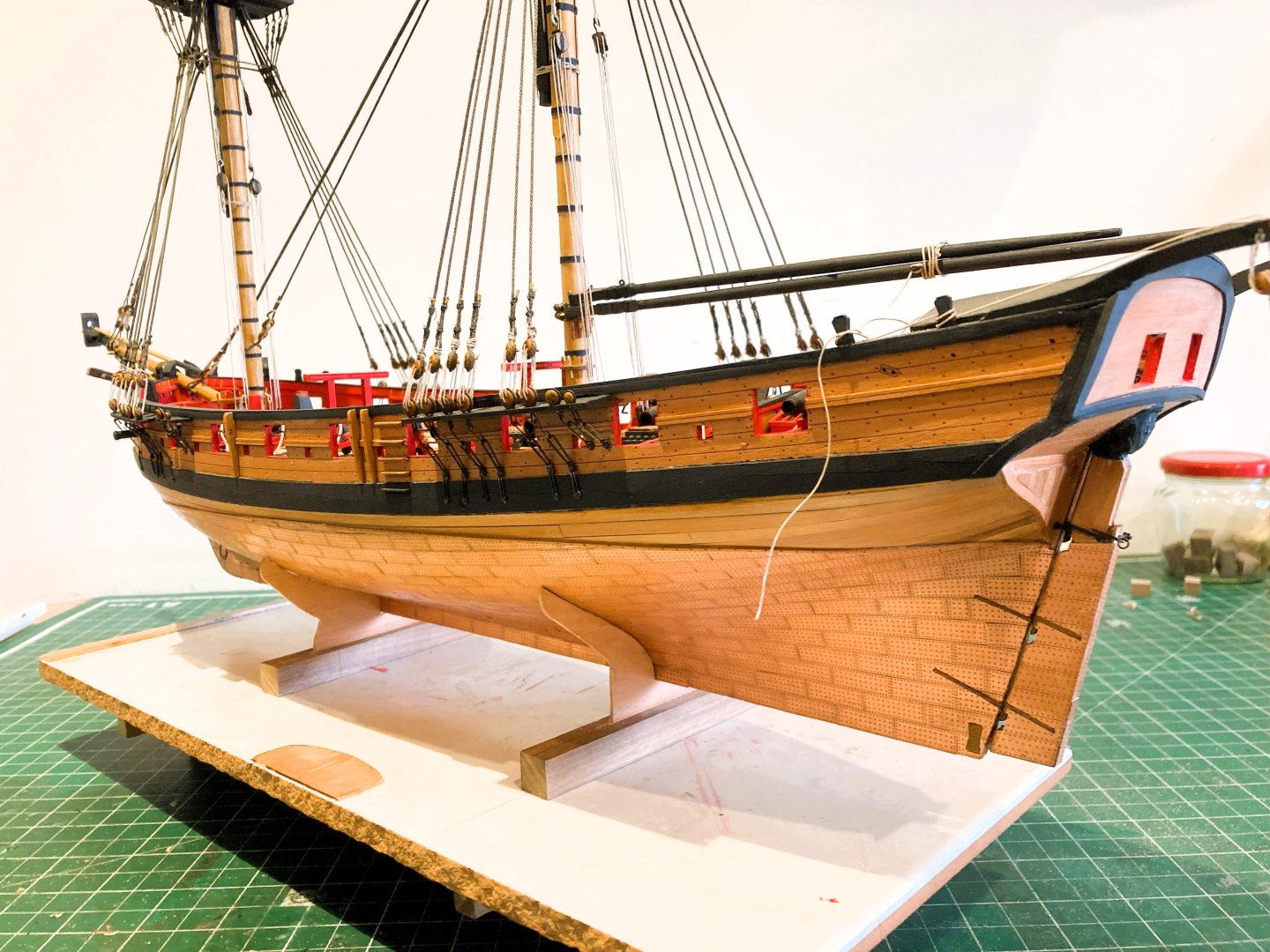
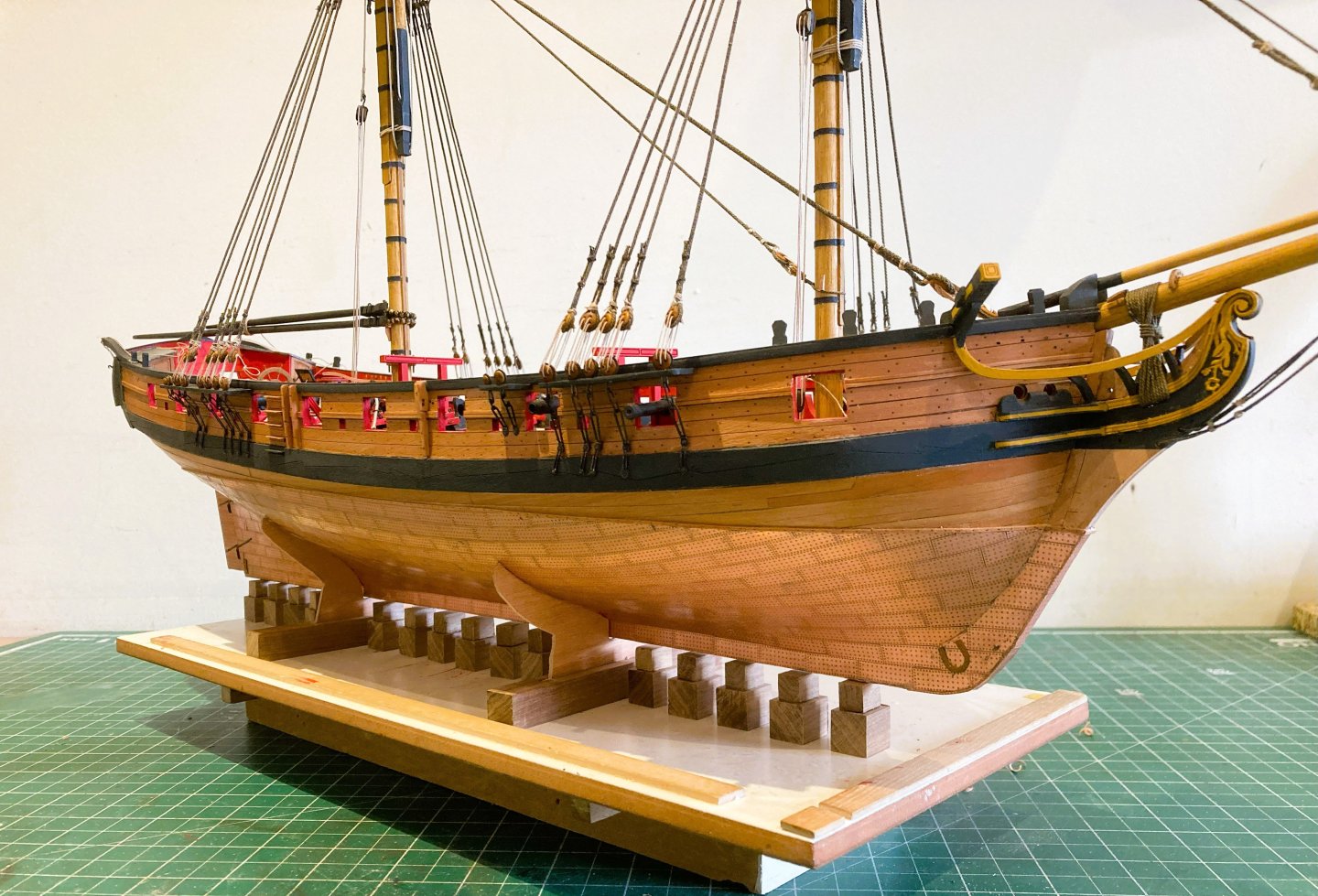
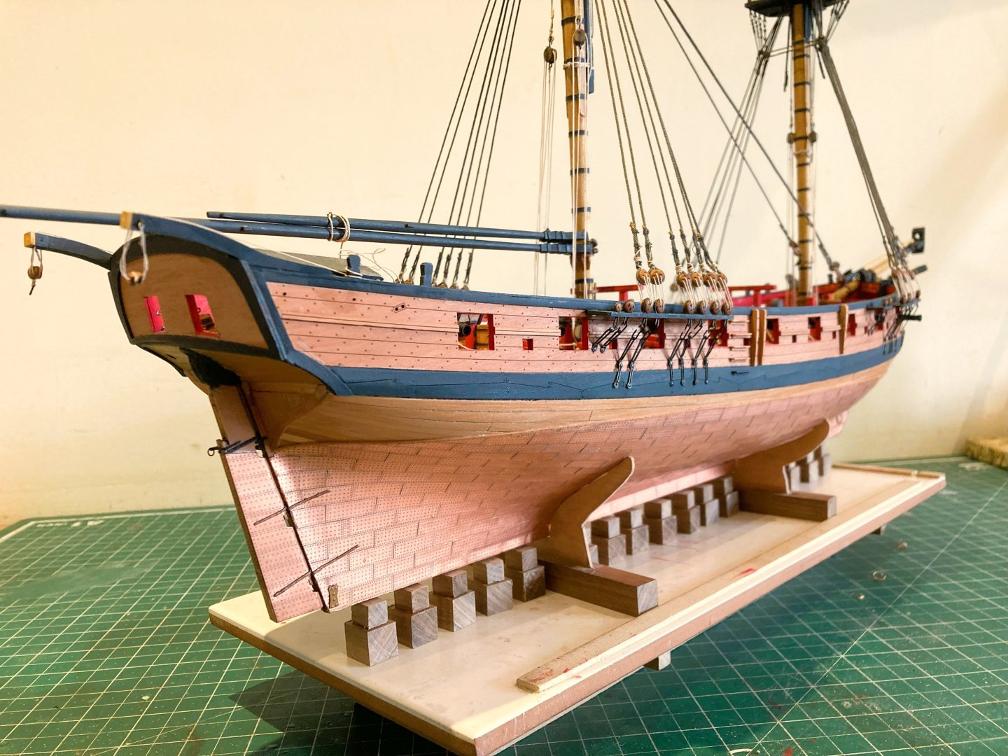
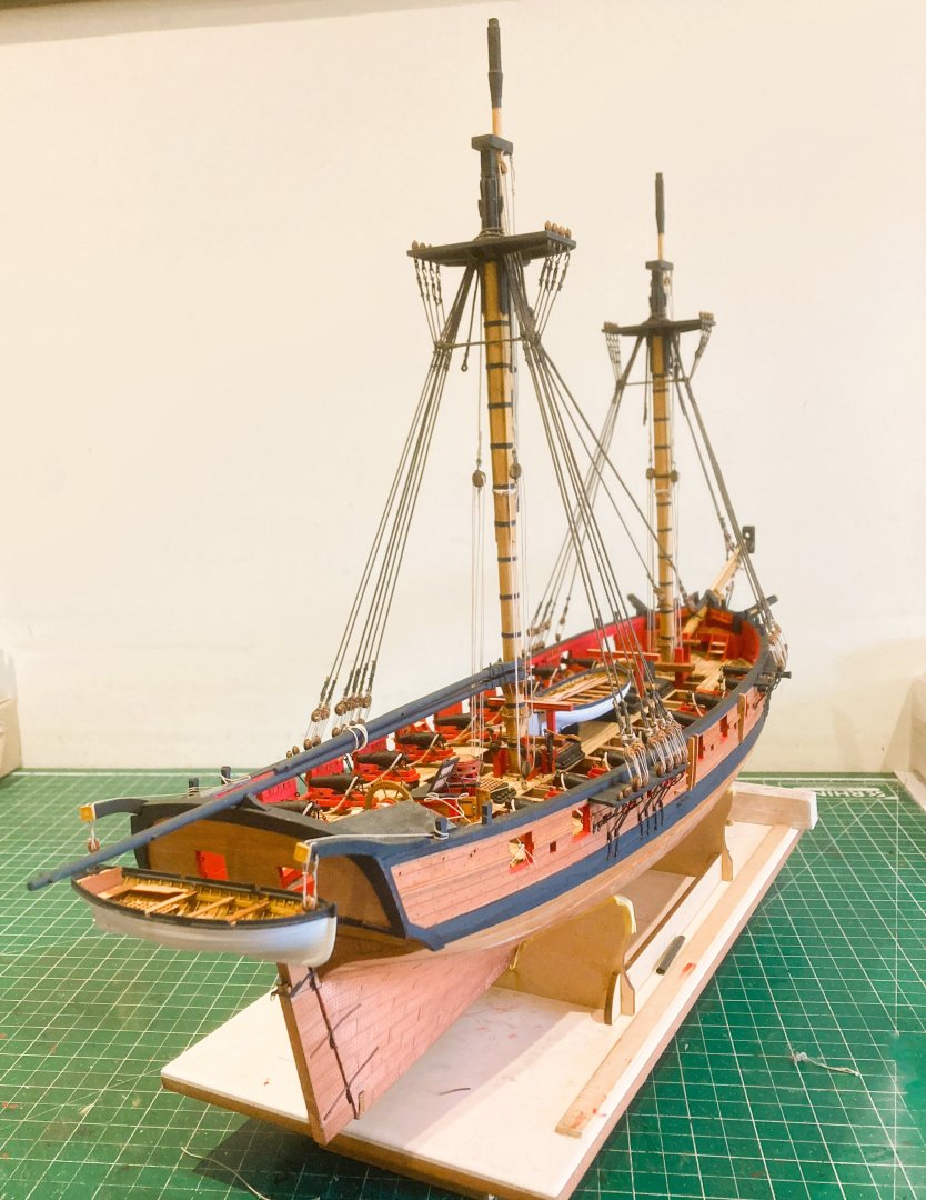
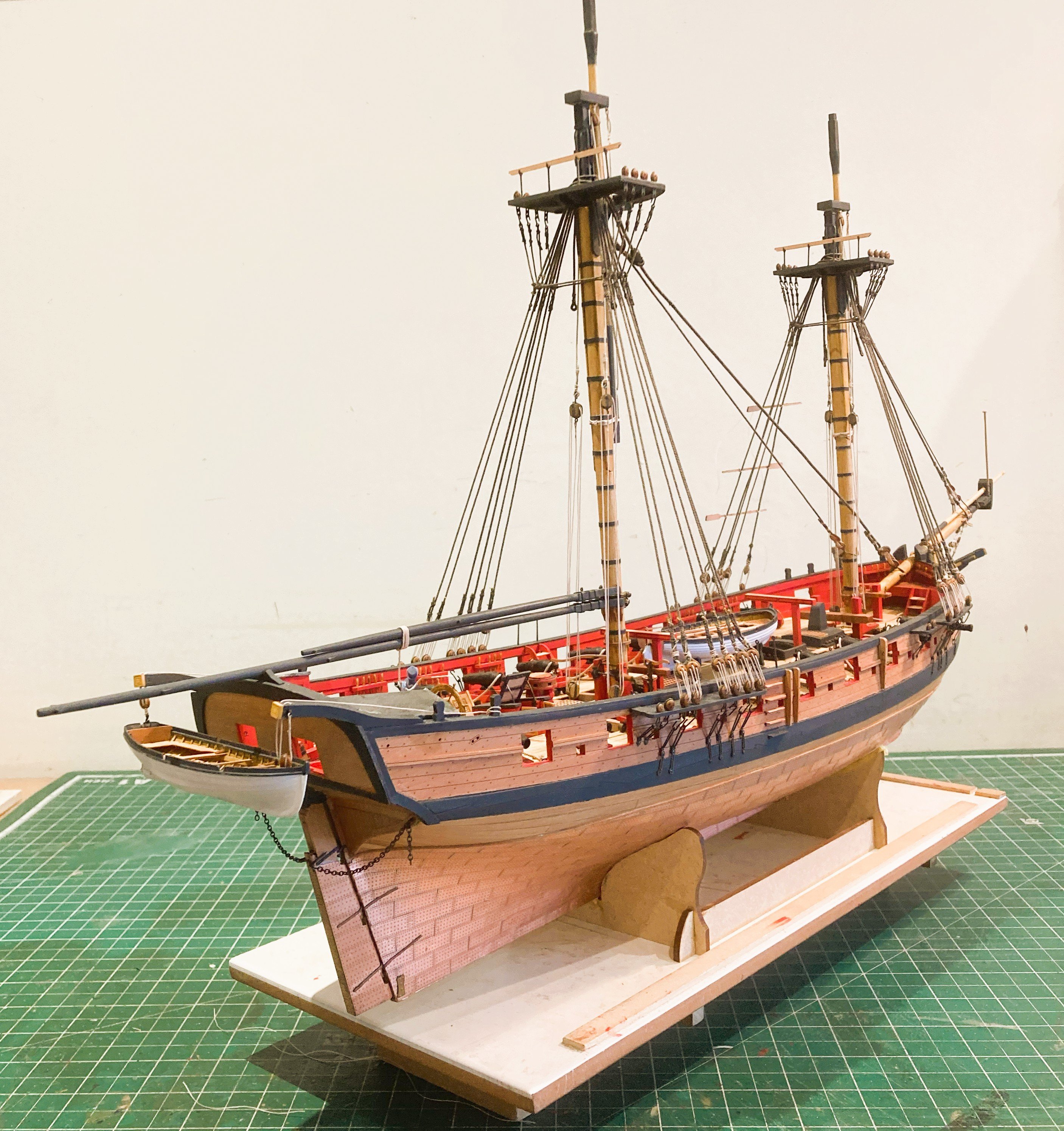
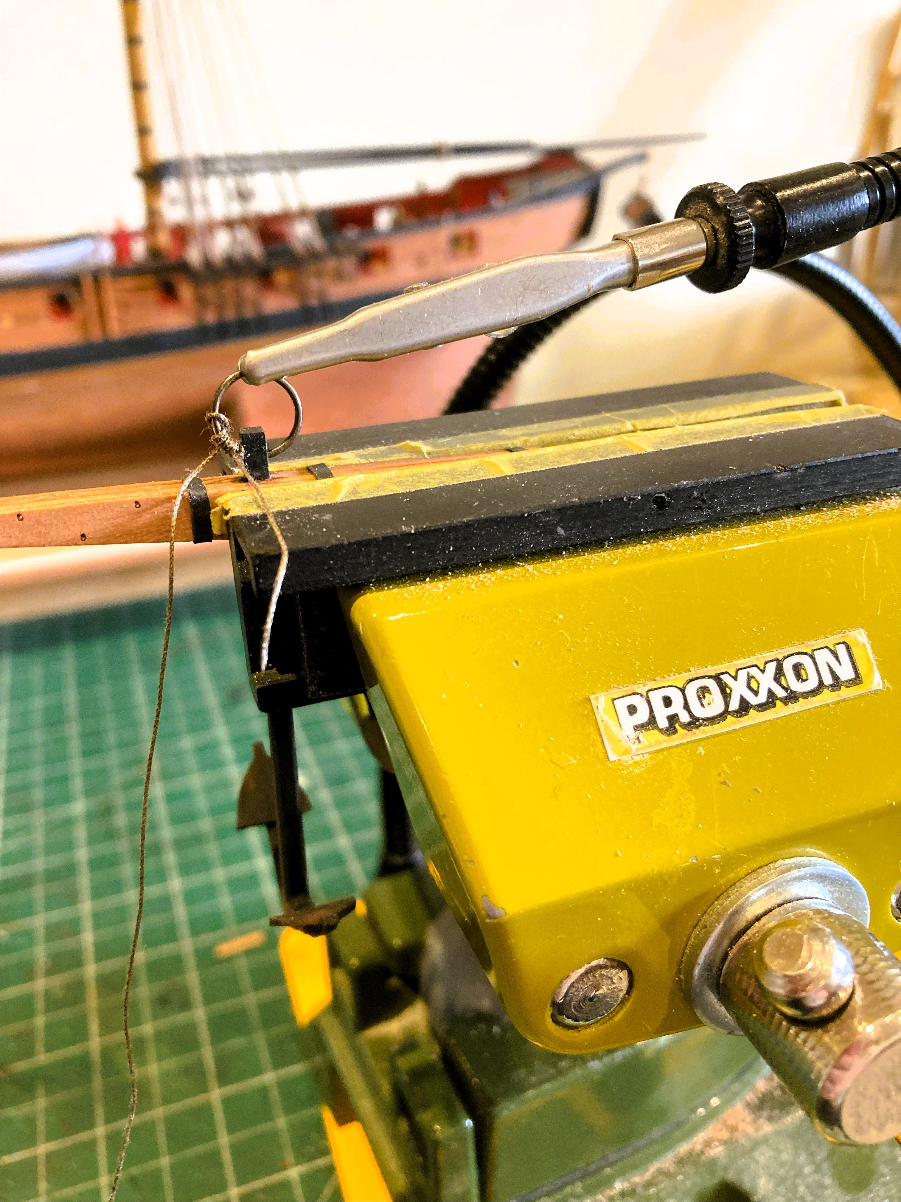
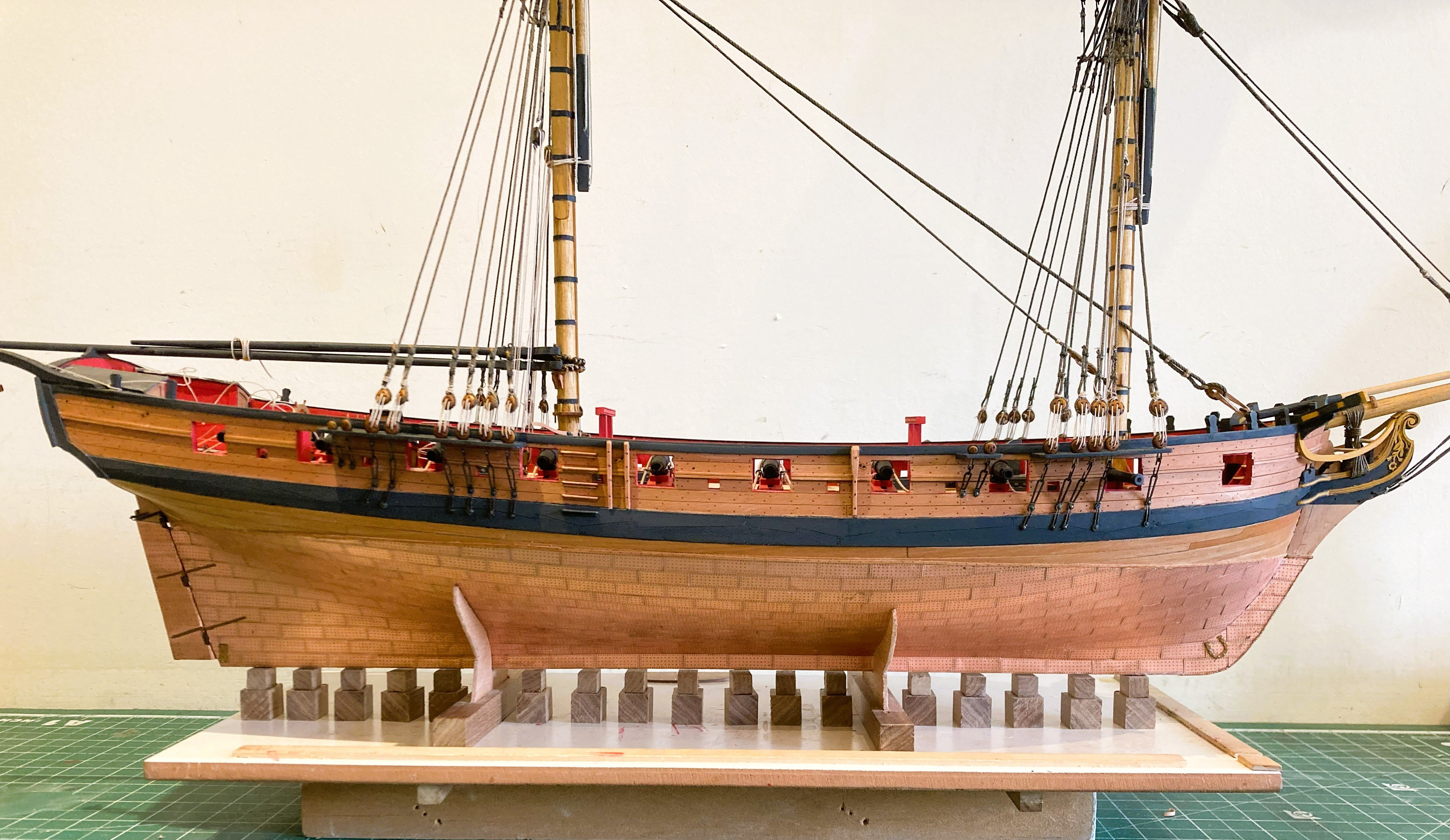
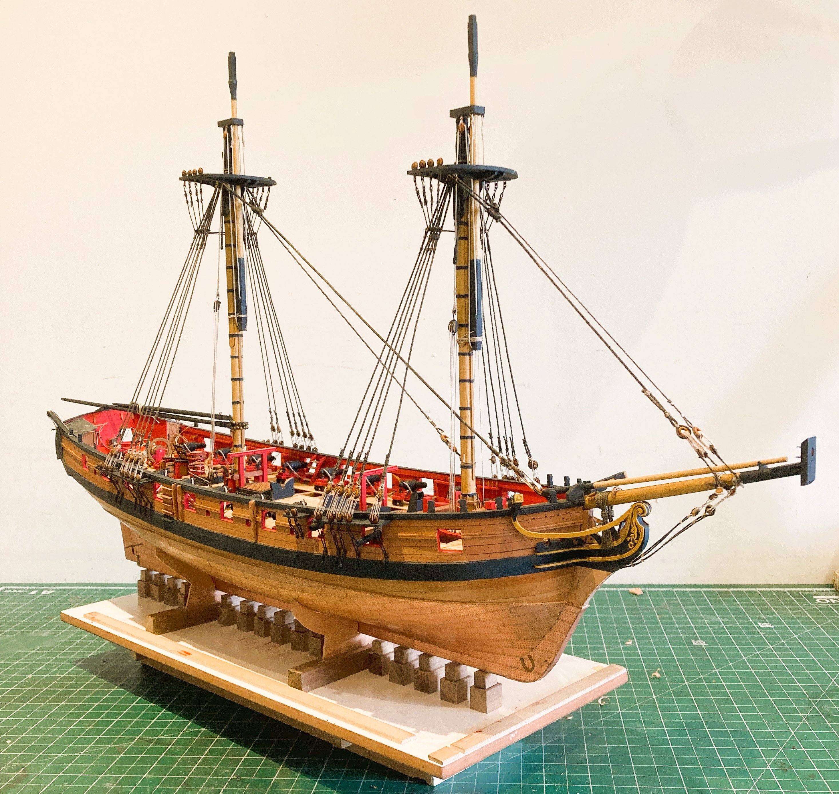
Thinking about display
At this stage I am beginning to formulate how the completed model will be displayed.
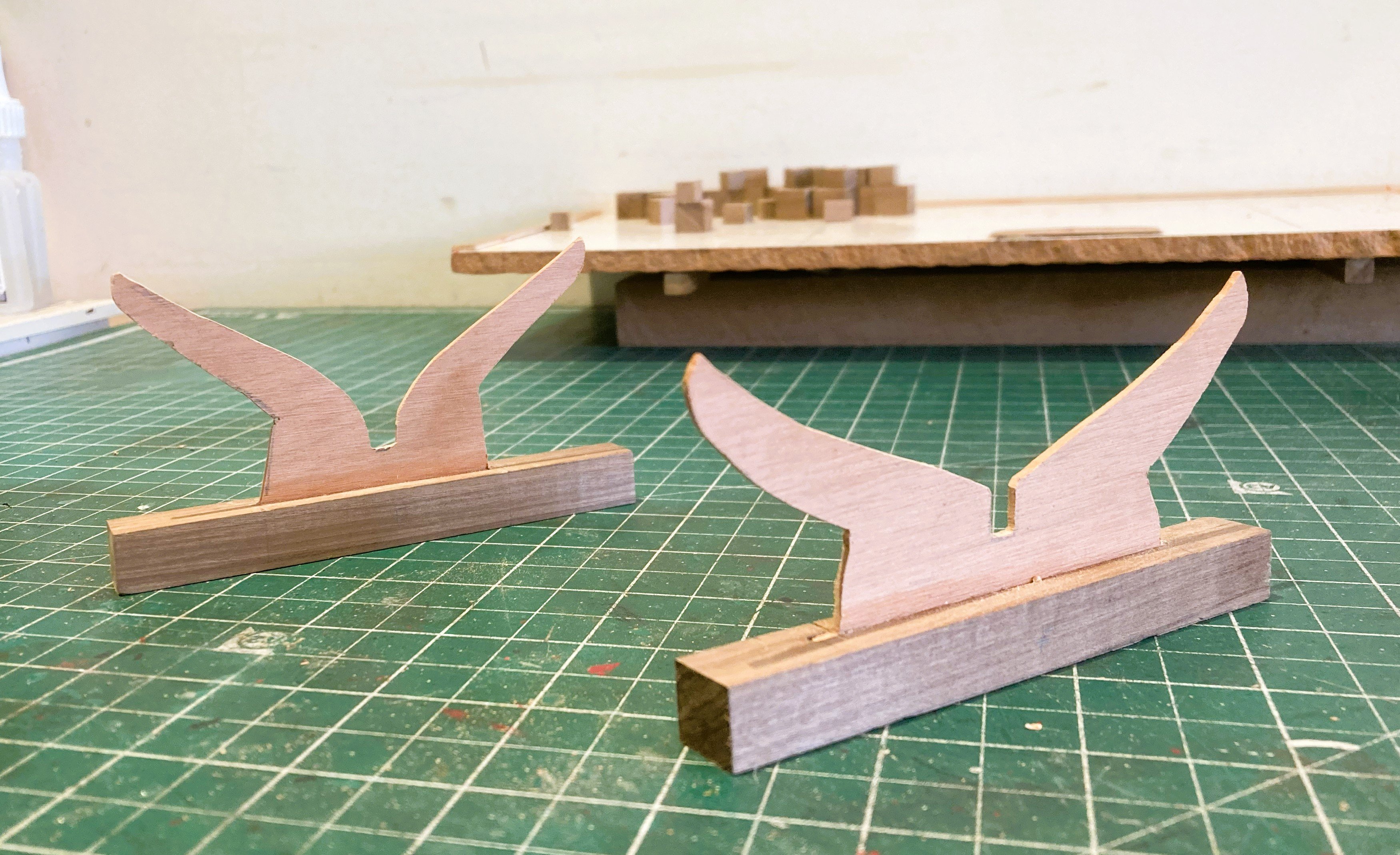
I have decided She will sit on keel blocks, an arrangement I used both in my Pegasus and Pickle builds.
Sections of 12mm and 8mm Walnut square stock are used to form the blocks, and cradles of reduced profile cut from 2mm Pearwood sheet.

5172a
Two lengths of 12mm square walnut are slotted to take the cradles.

5174a
5175a
A fair bit of tweaking required to get a reasonable fit.
5177a
5179a

5180a

5178a
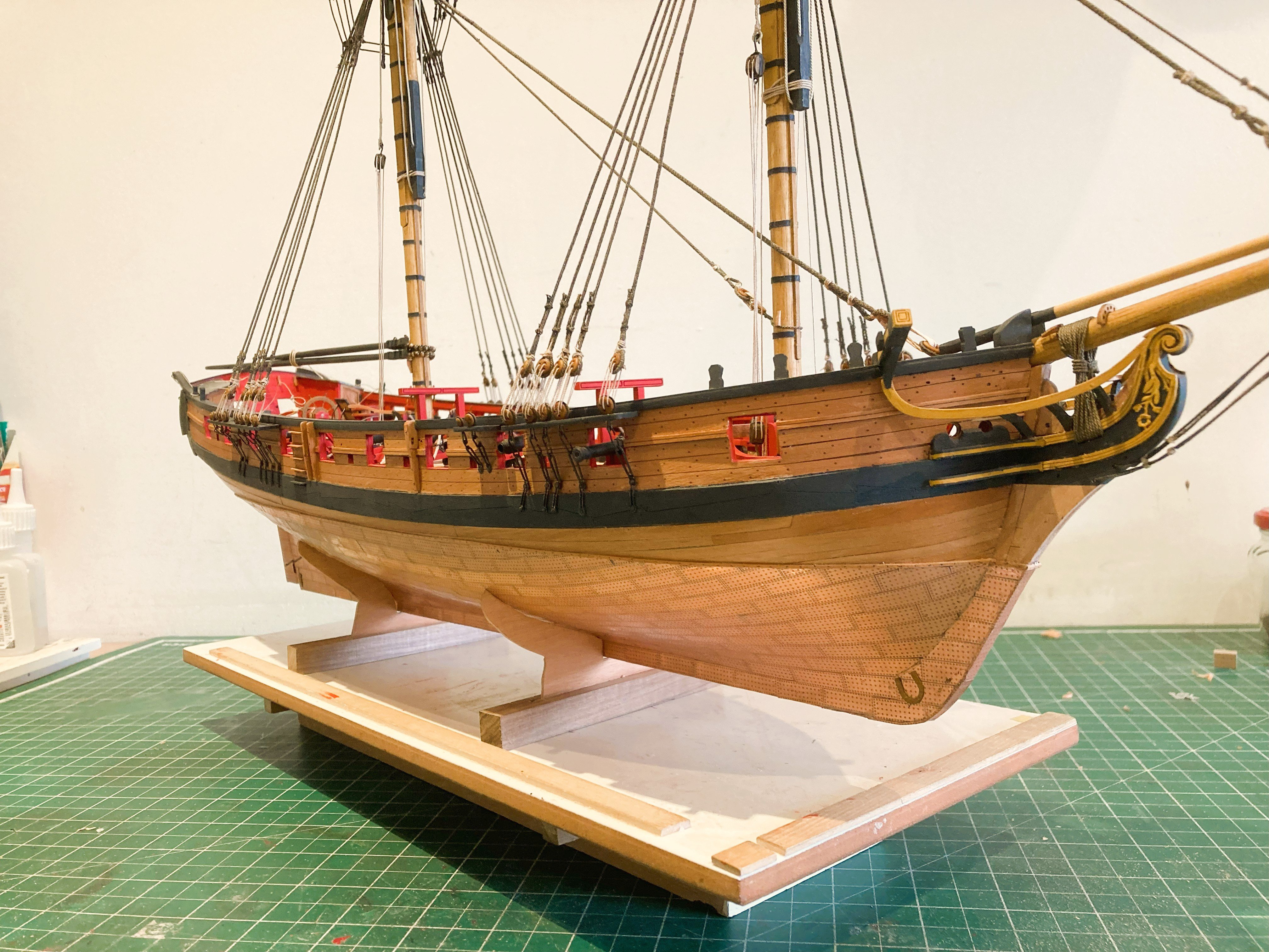
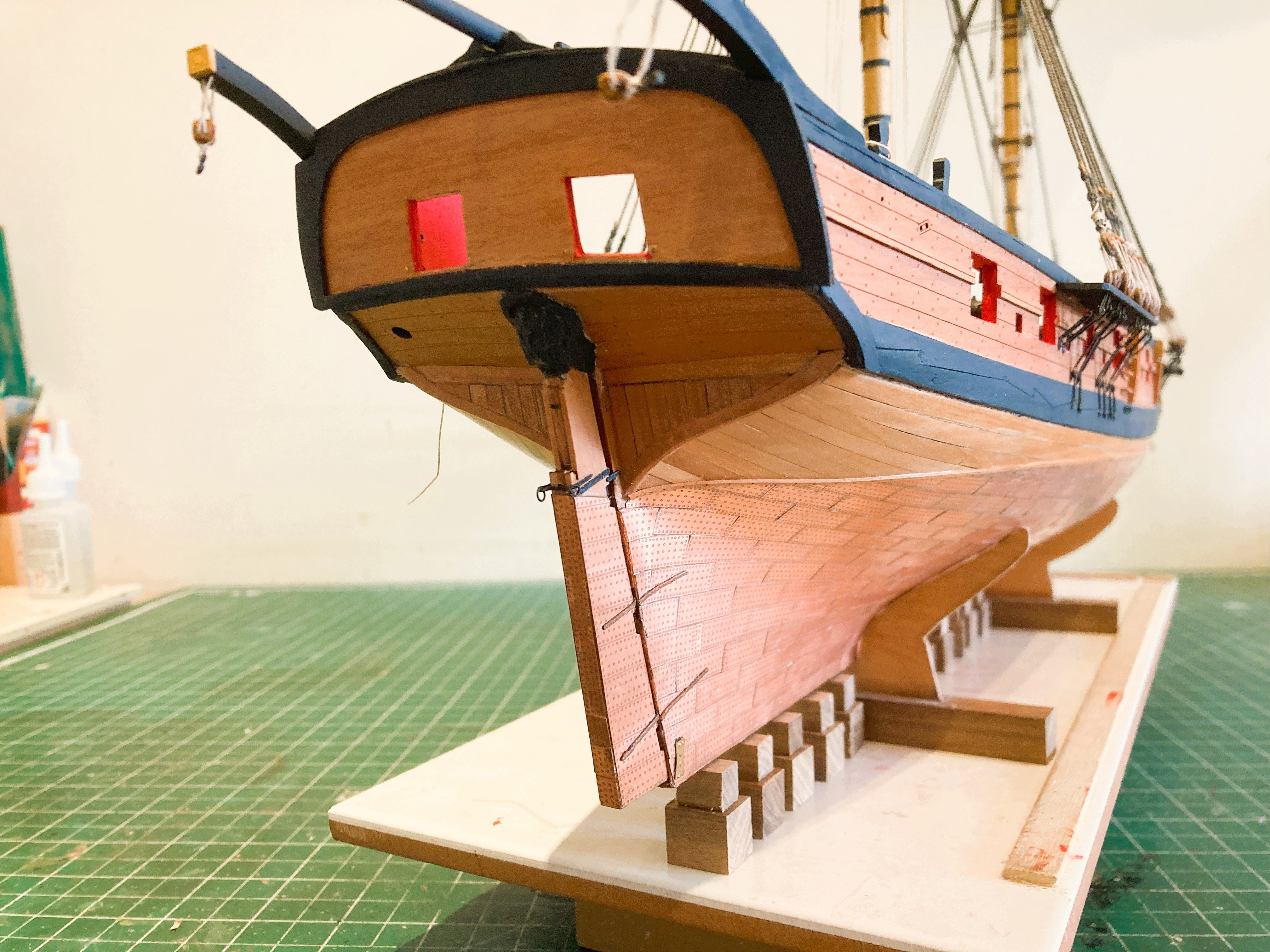
Trying out the keel blocks. The tricky part will be setting them out on the base board, yet to be made.

5176a
An Acrylic cover to protect Harpy has been ordered.
The dimensions of 800mm (w) x 450mm (h) x 190mm(b)
are the minimum I can get away with, but a significant saving on space.
B.E.
26/07/2025
-
Thank you David and Don, and for those who have followed and 'Liked'
@David - I think you may have begun a new trend . Needs must in my case, but if you go down that road it does involve adding extra detail to the lower sections of the Topmasts in the form of octagonal/ square sections and the cutting of sheaves at an angle thro' the mast, a bit of a tricky exercise.🫤
Cheers.
B.E.
-
Post 101
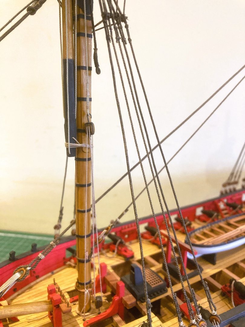
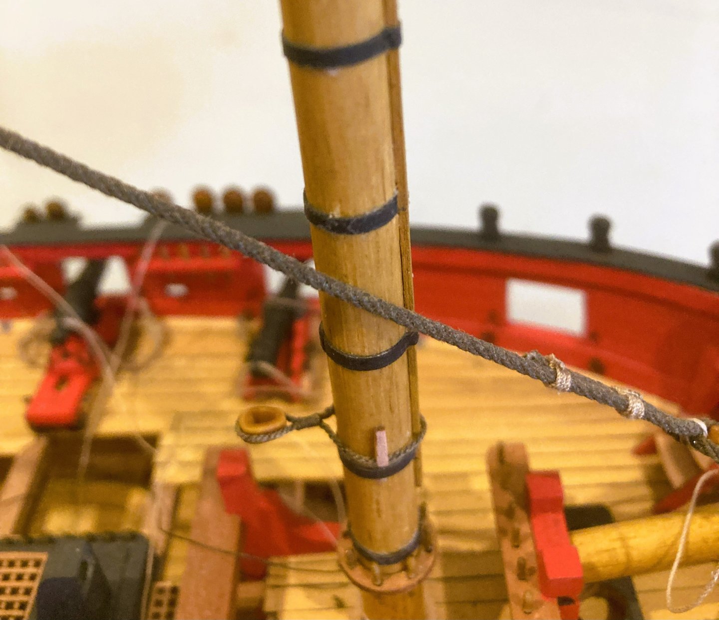
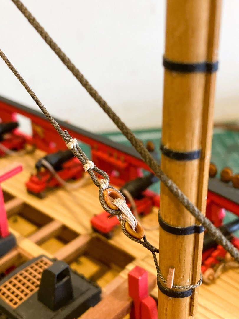
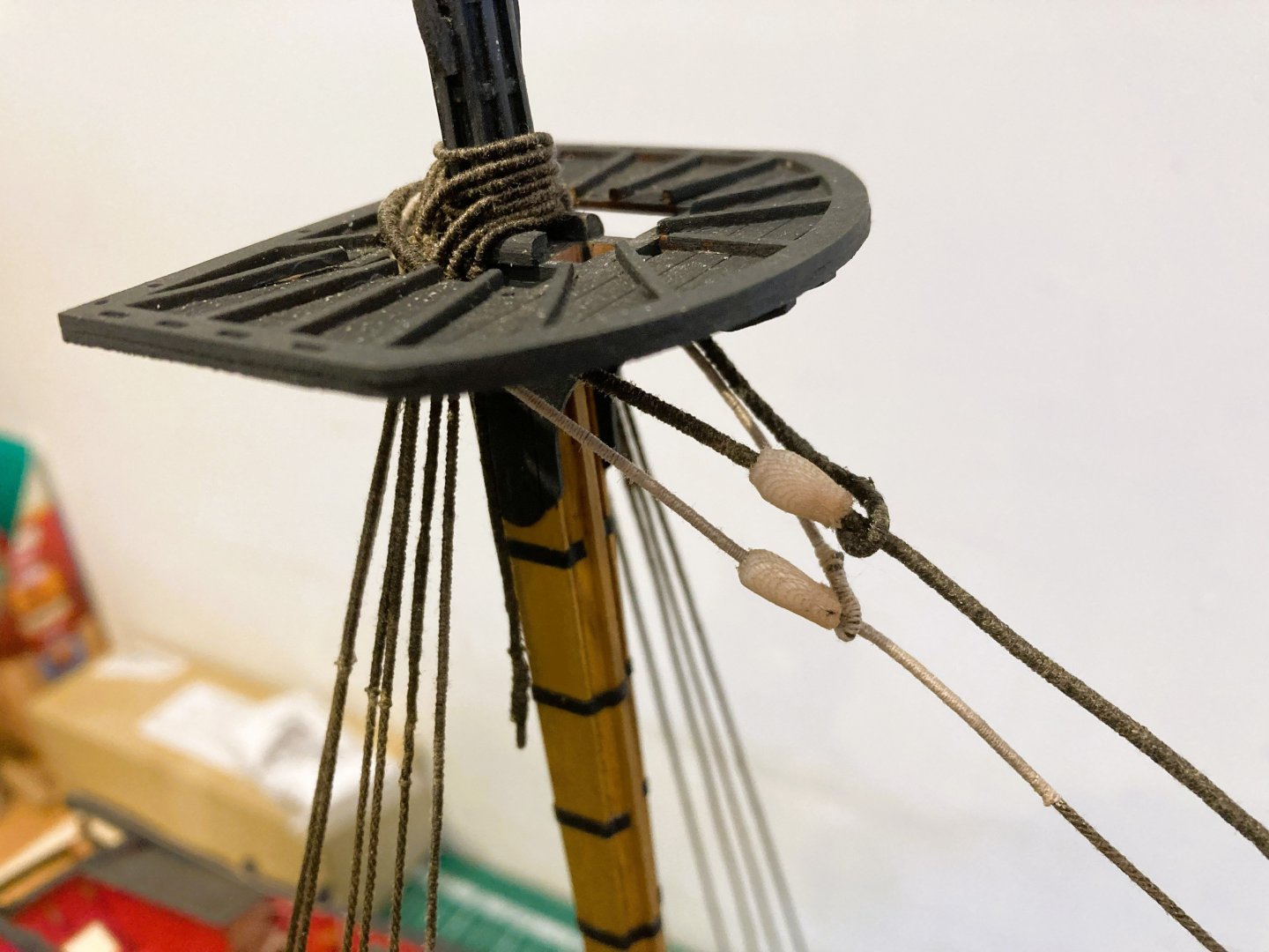
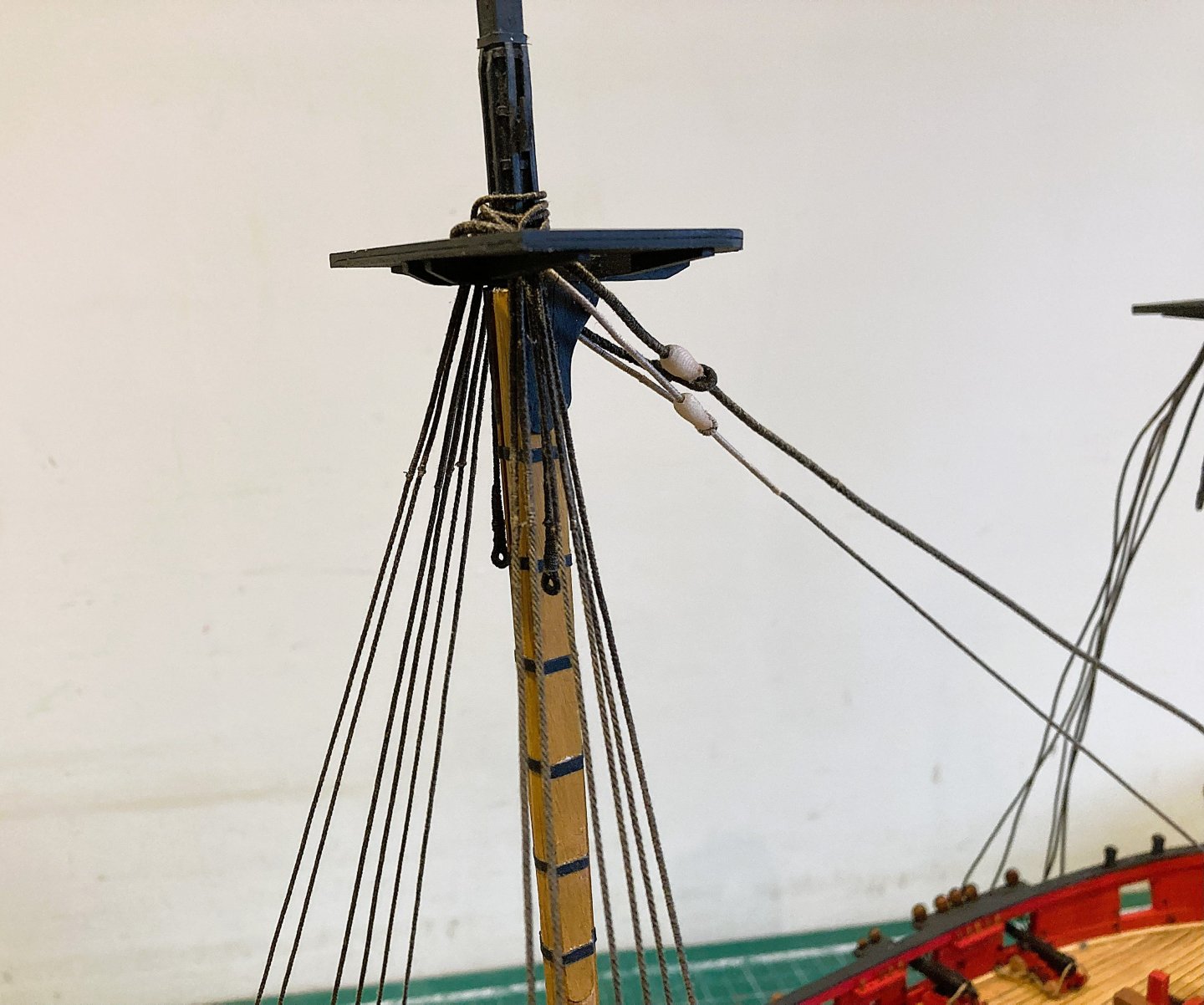
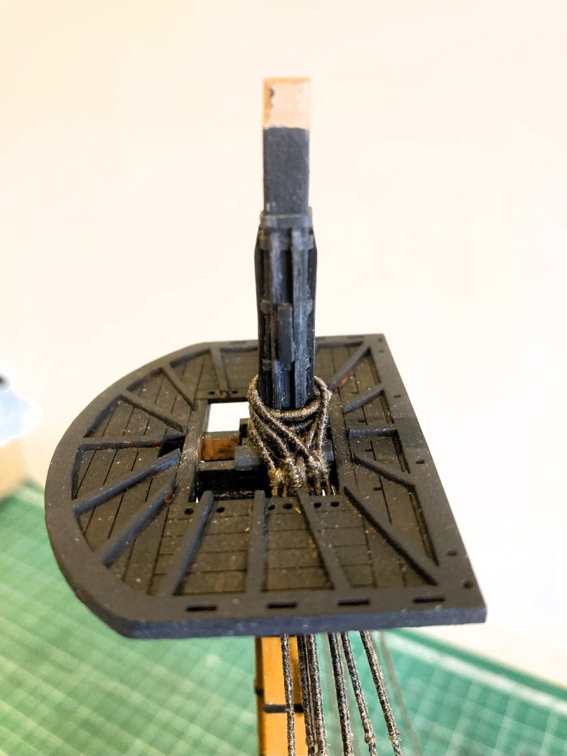
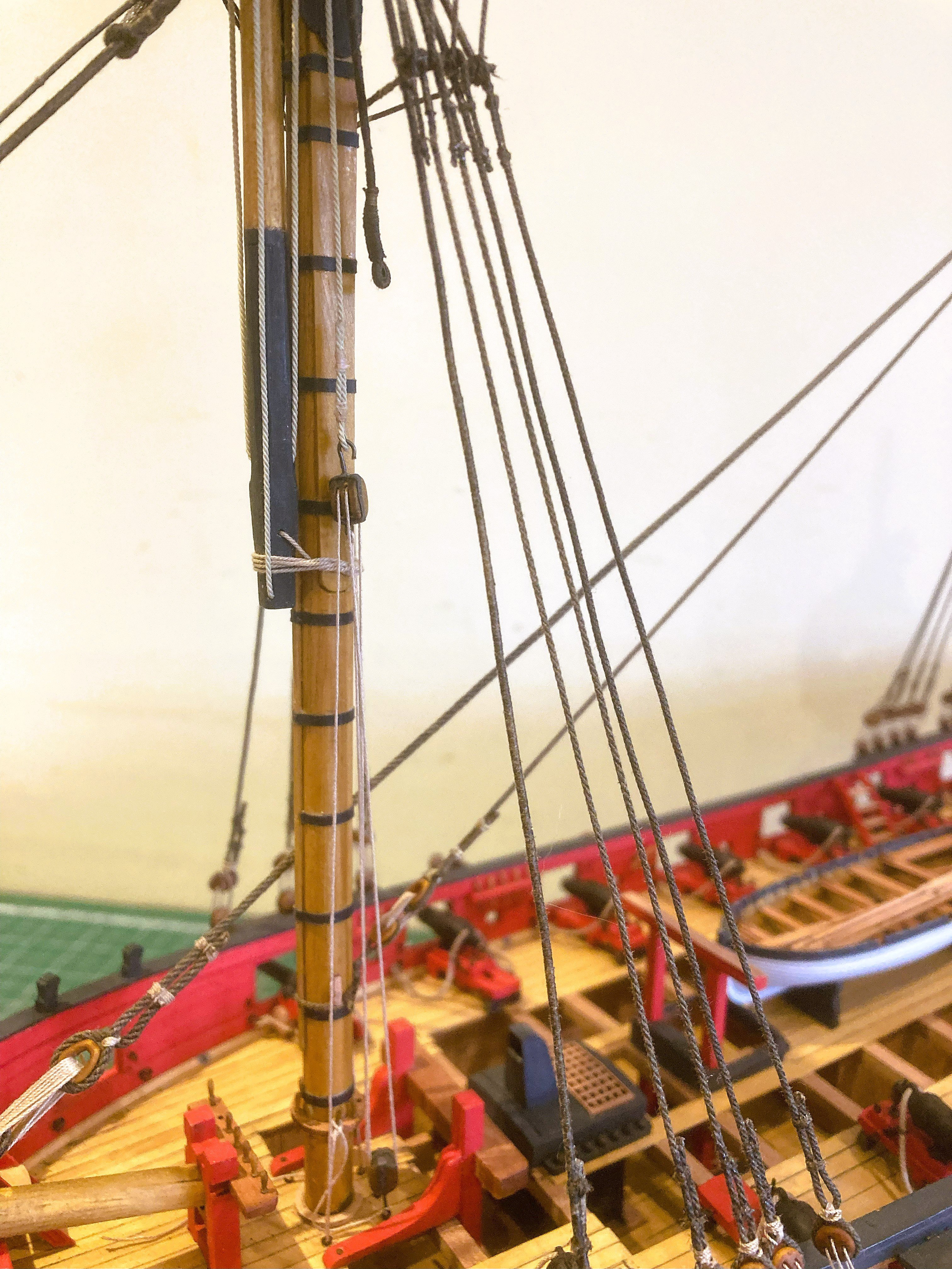
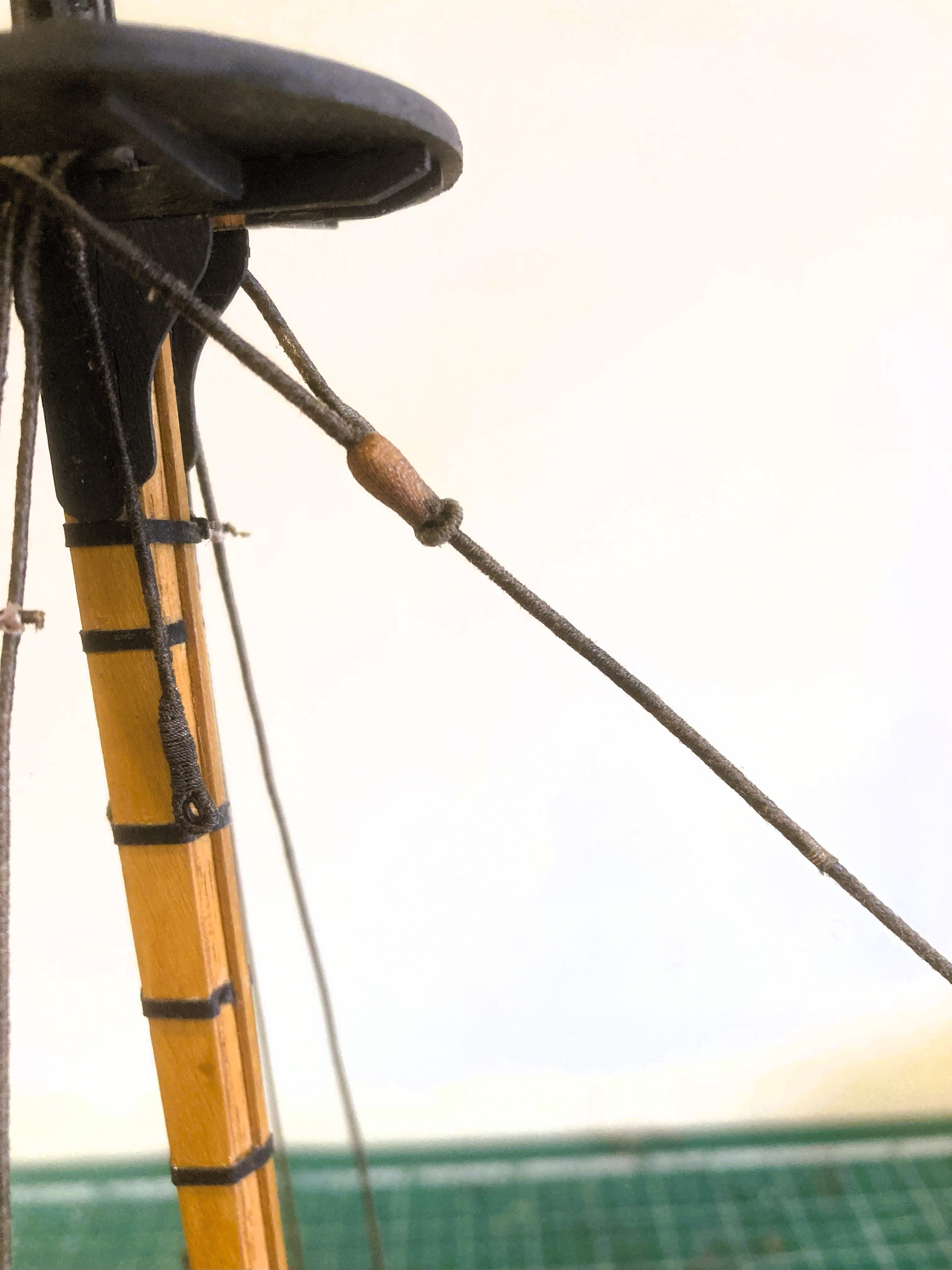
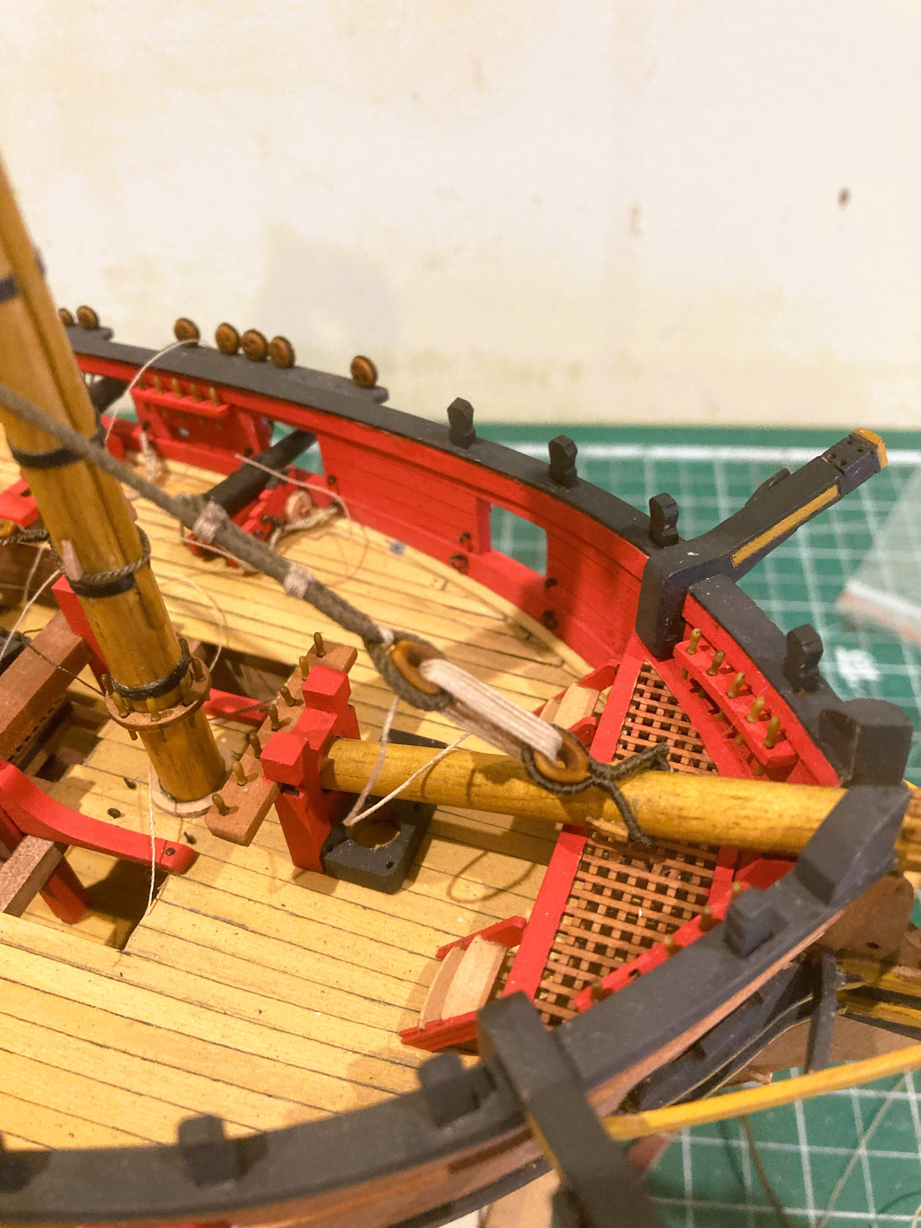
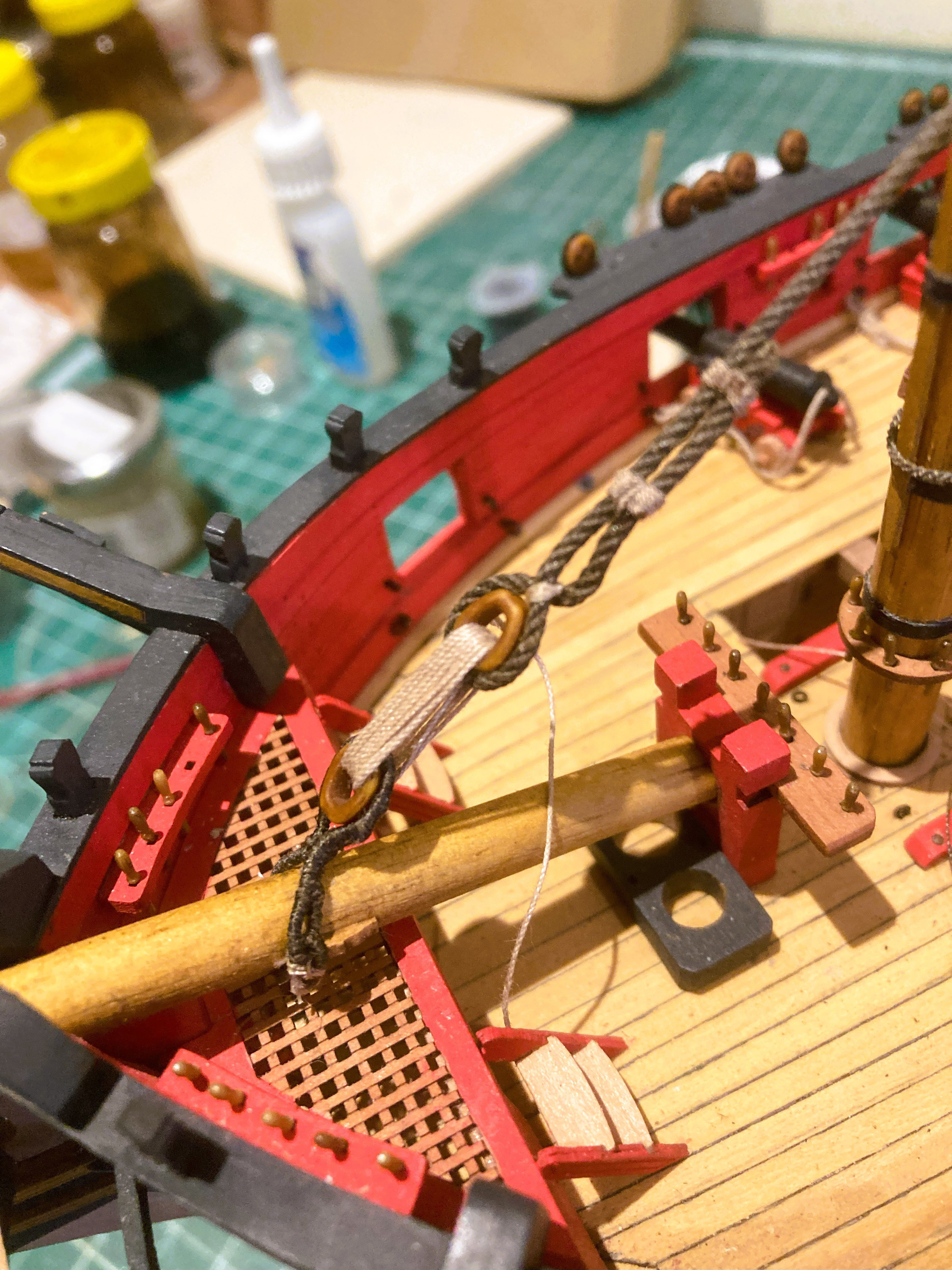
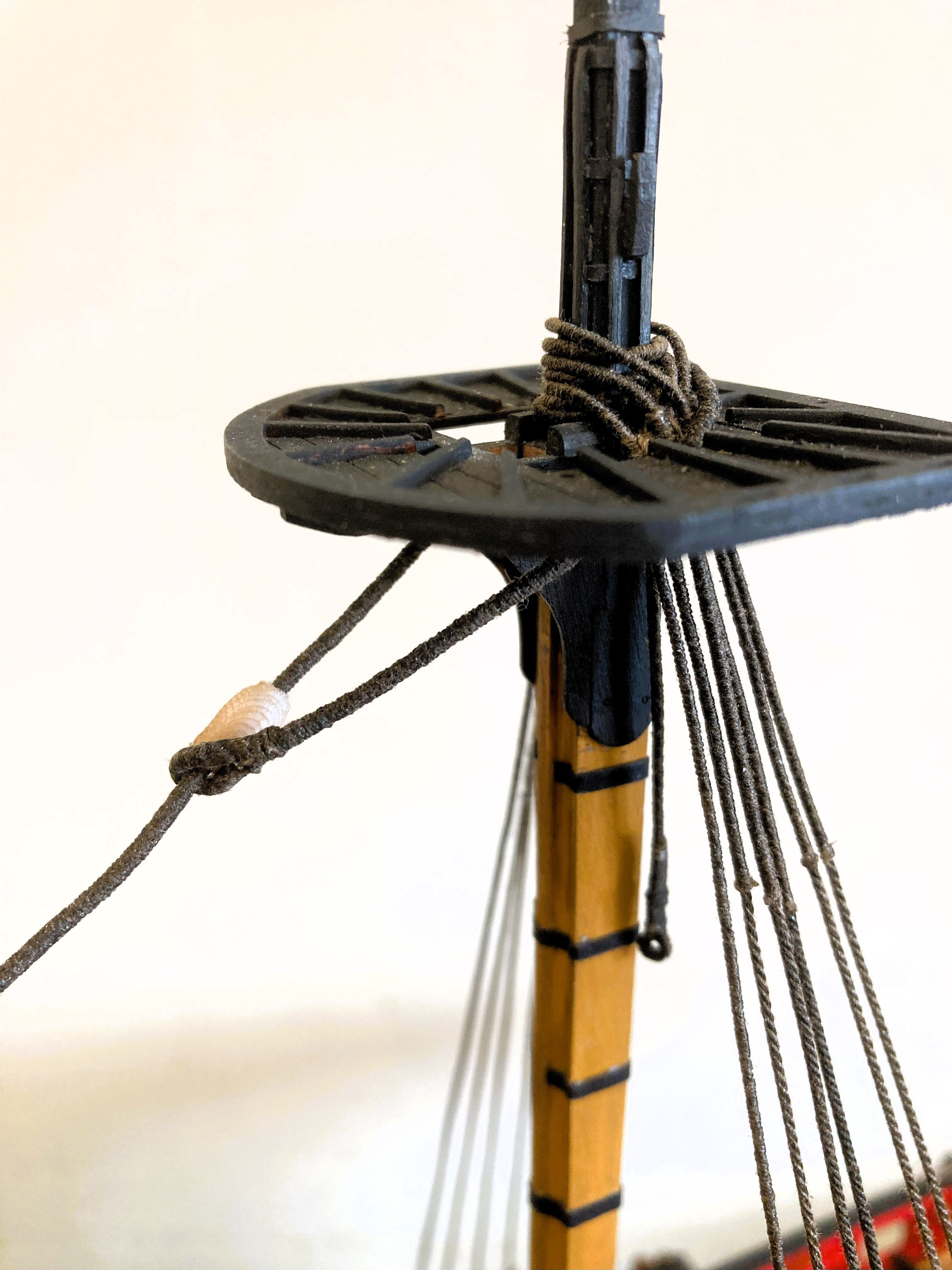
Topmast Rigging
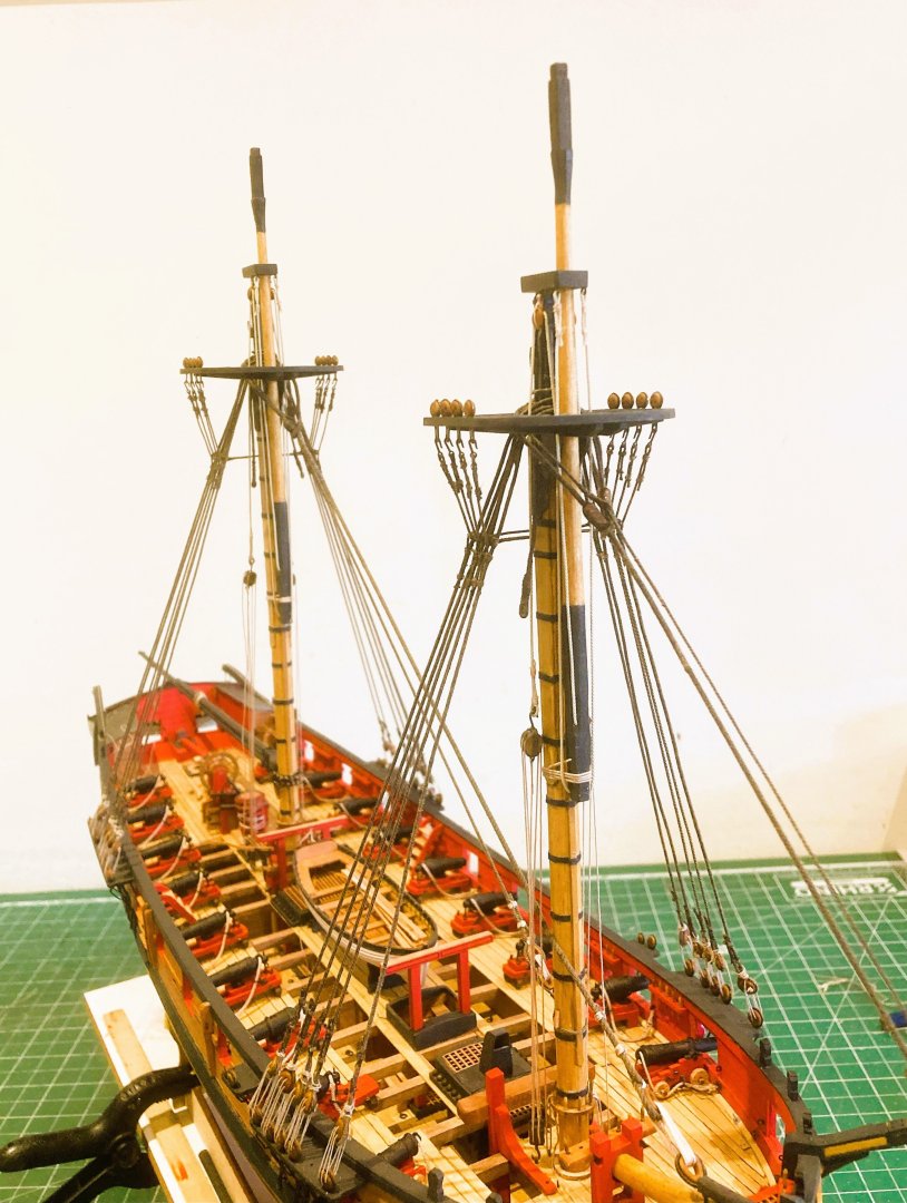
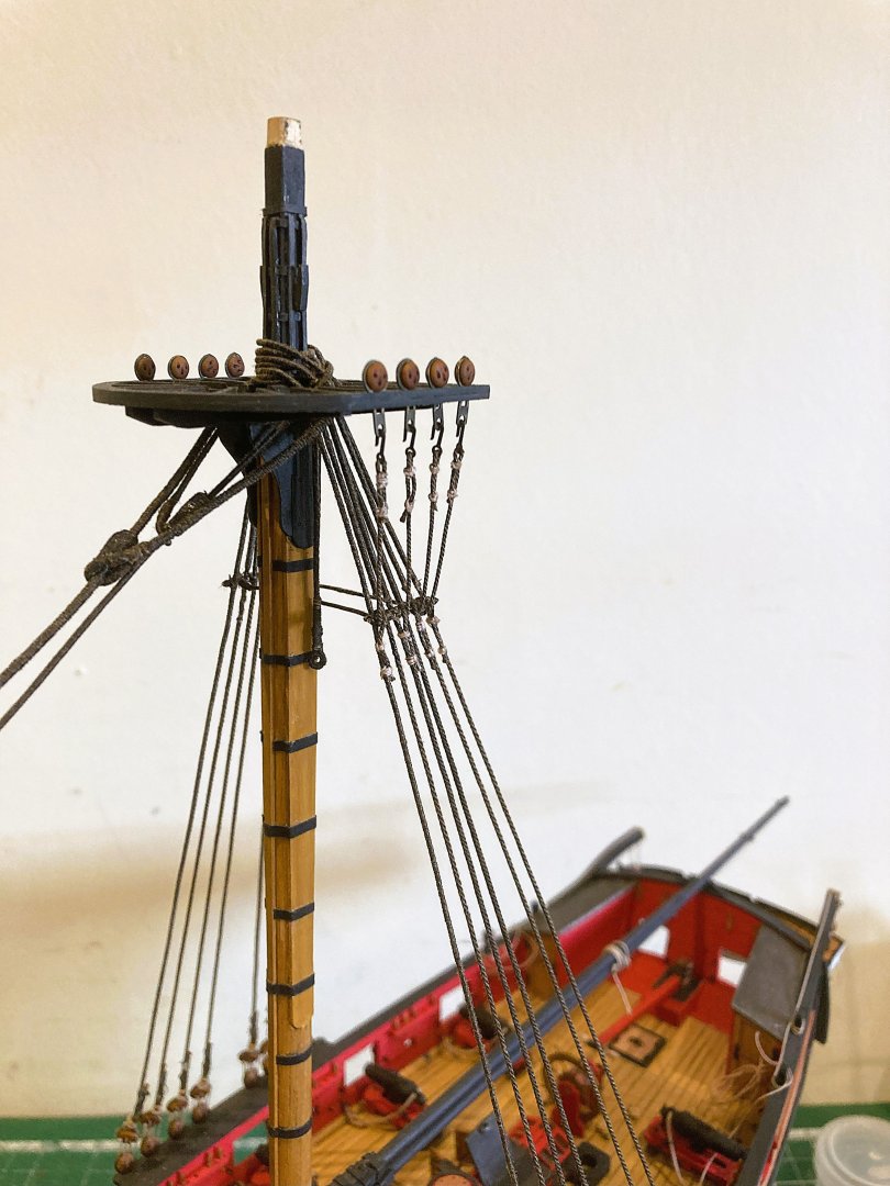
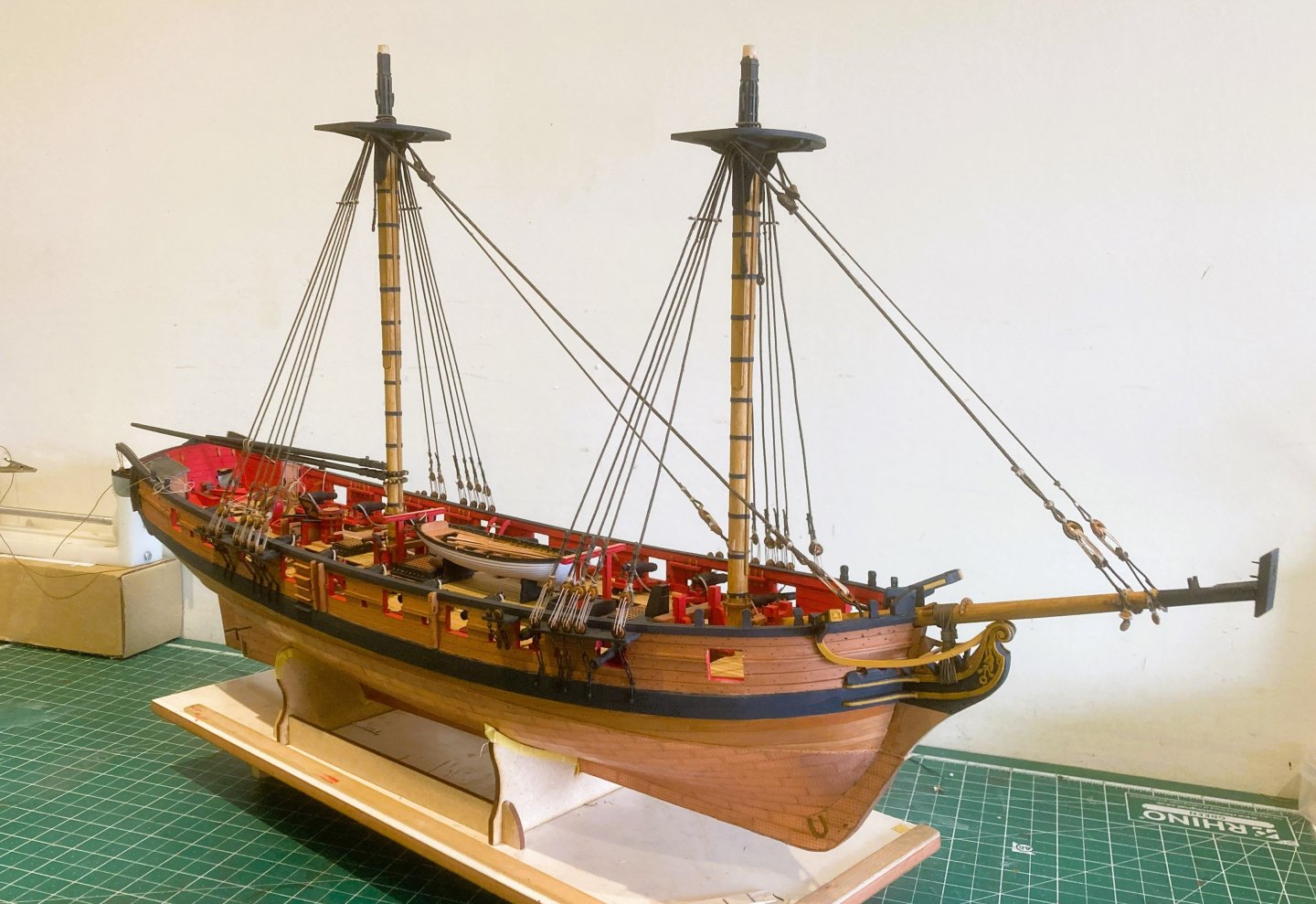
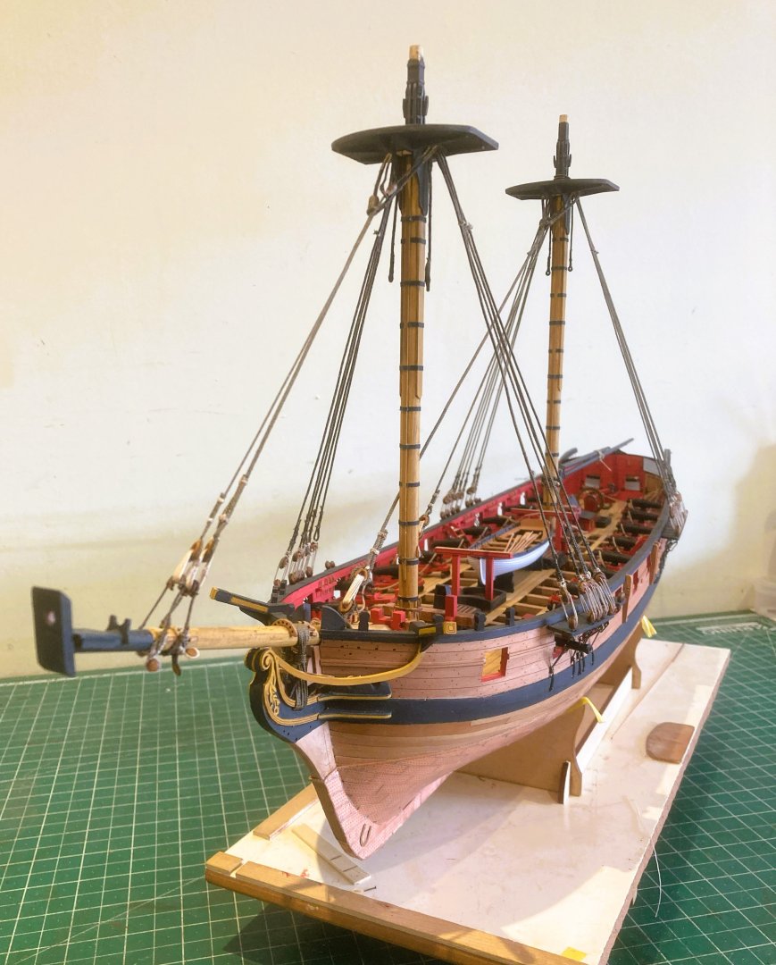
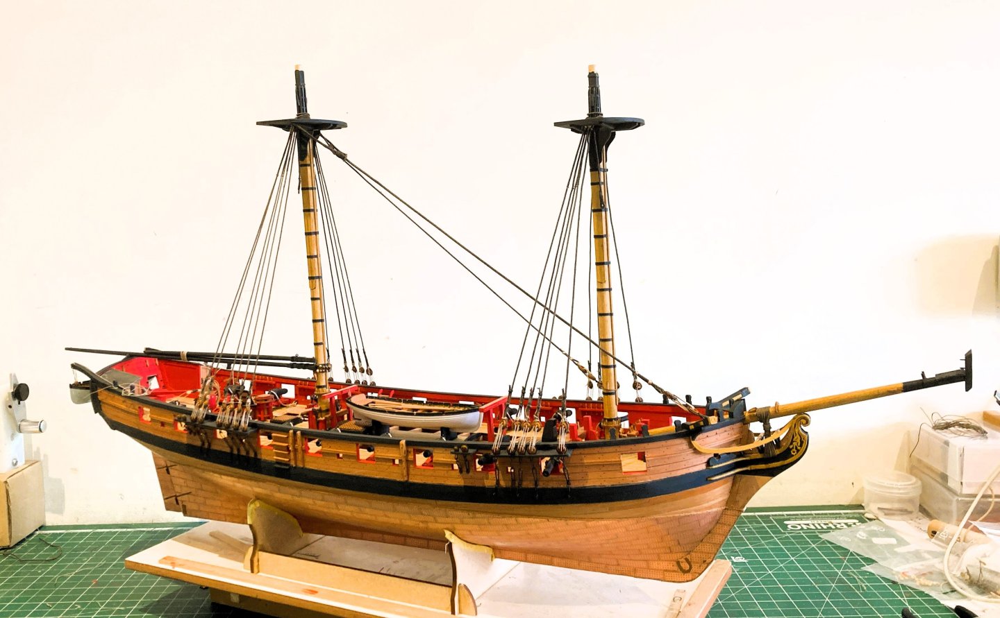
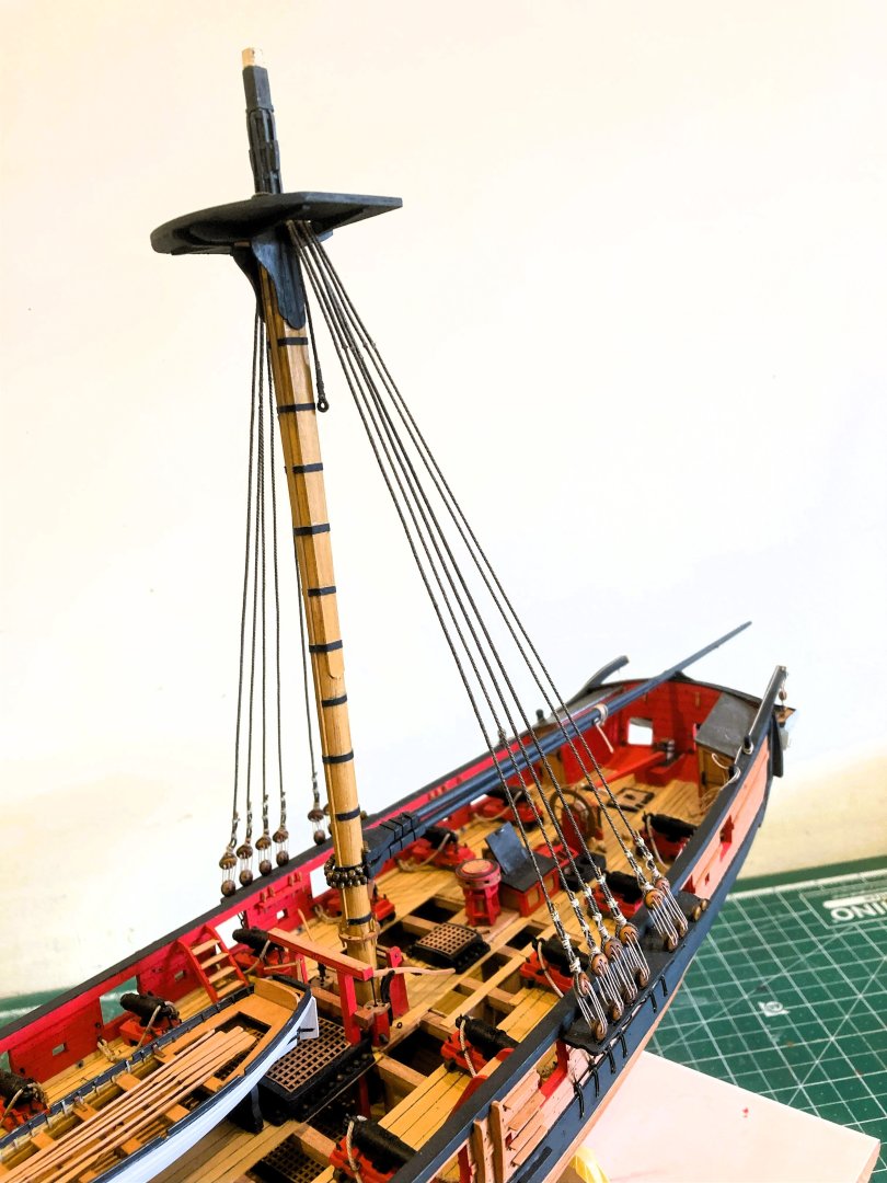
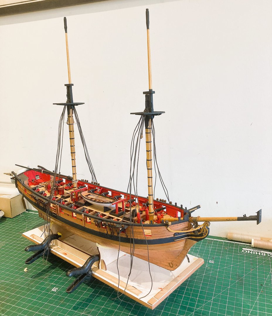
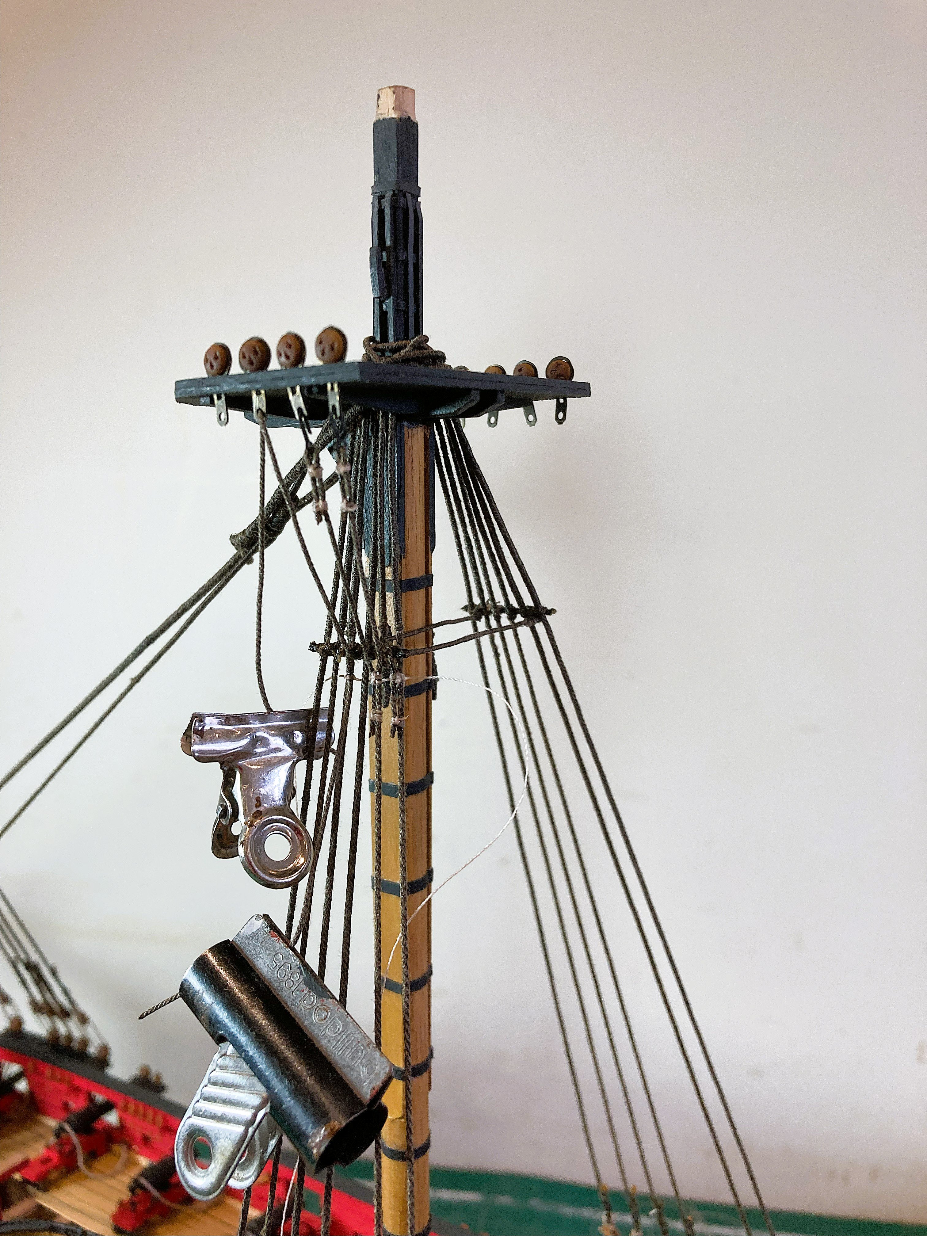
I have rigged the Topmasts in a lowered position mainly for space saving purposes, but also as an alternative to storing them on the Gallows.
This involves rigging the Topropes to support the masts.
Fortunately this procedure is covered in the books Seamanship in the age of sail by John Harland, and The Masting and rigging of English ships of war by James Lees.
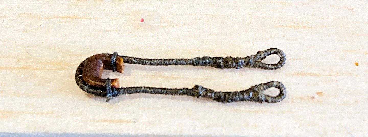
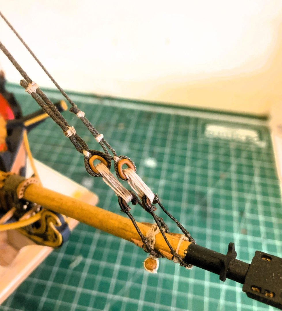
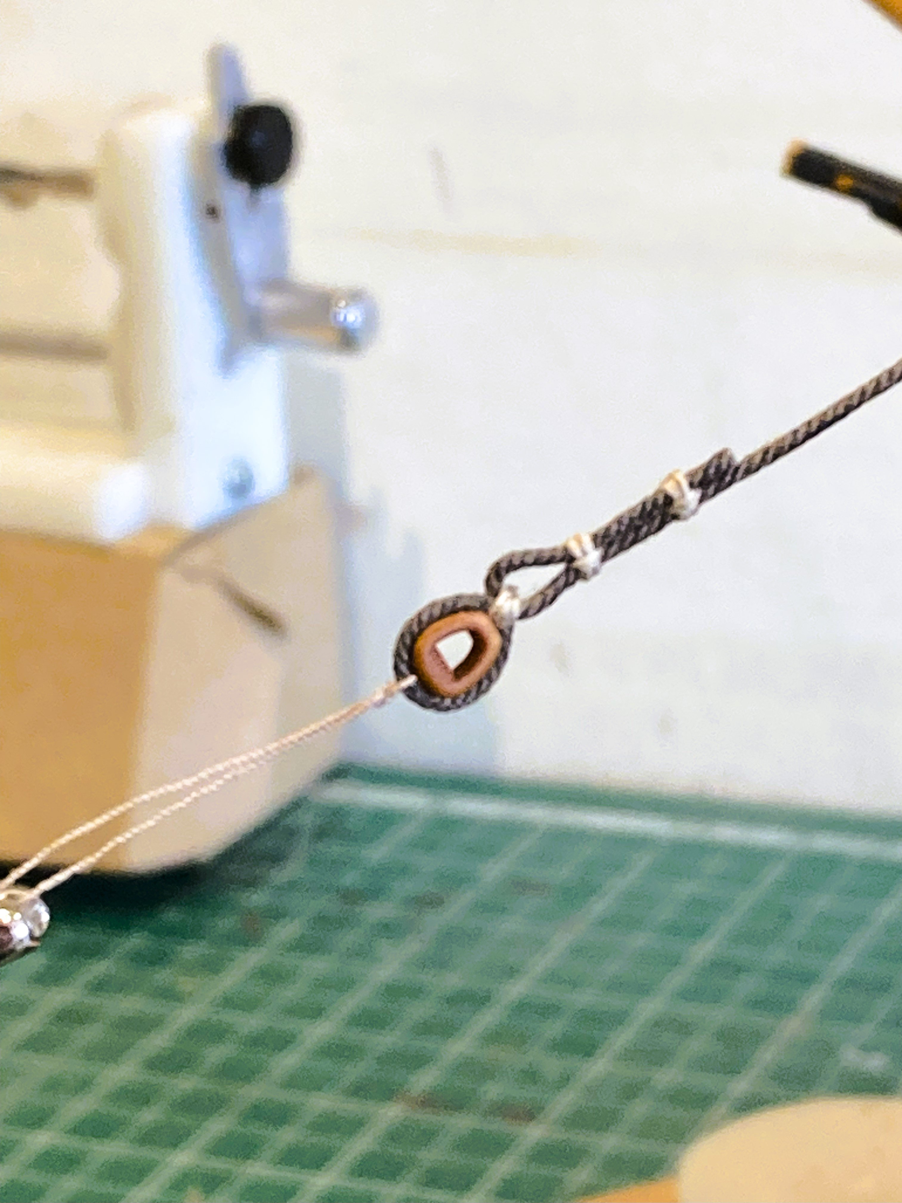
For the Toprope Pendents I’m using Morope 0.8mm polyester line, coupled with Syren 3/16” resin blocks, and 2mm thimbles.
For the Falls I am using Syren 0.3mm line coupled with ¼” Boxwood Double blocks.
Strictly speaking these should be iron bound blocks so a sliver of heat shrink tubing will be used to represent the ‘iron’
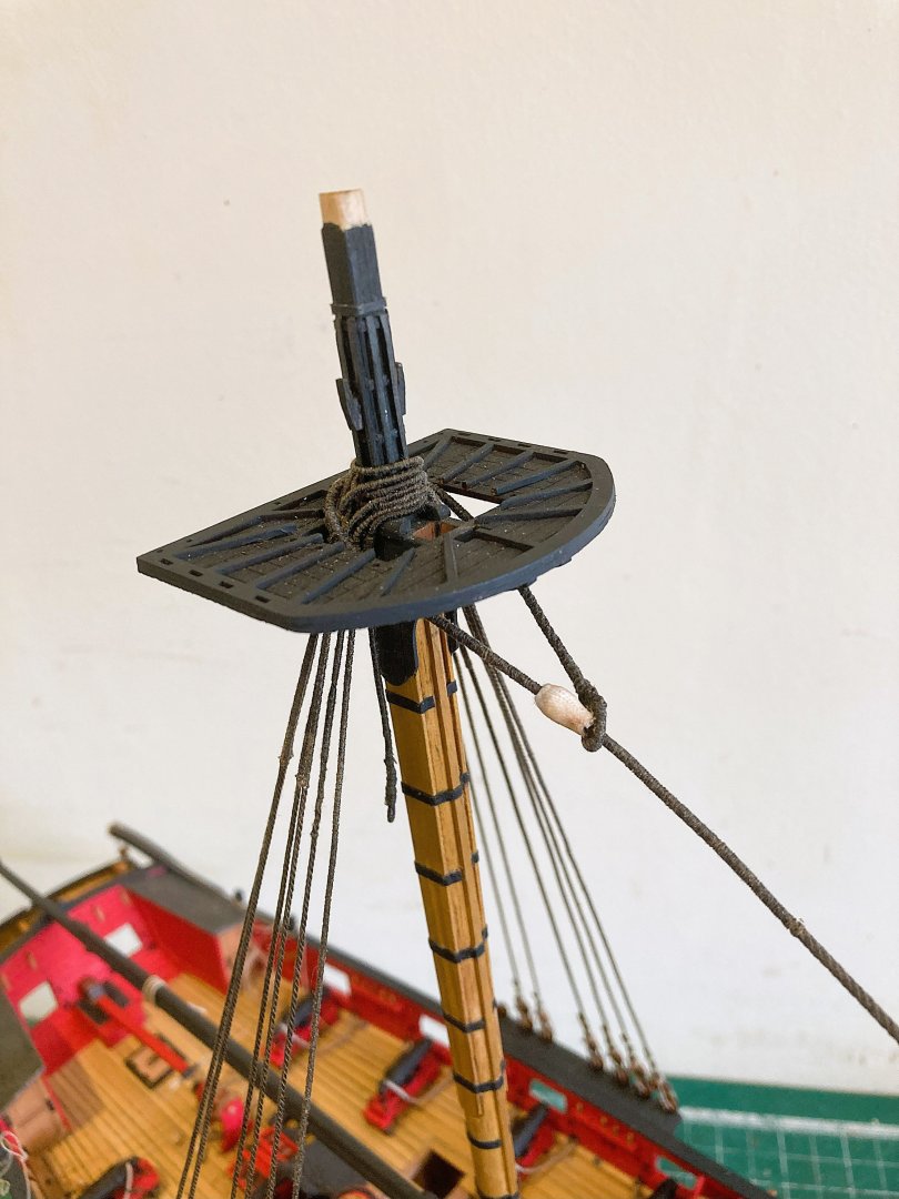
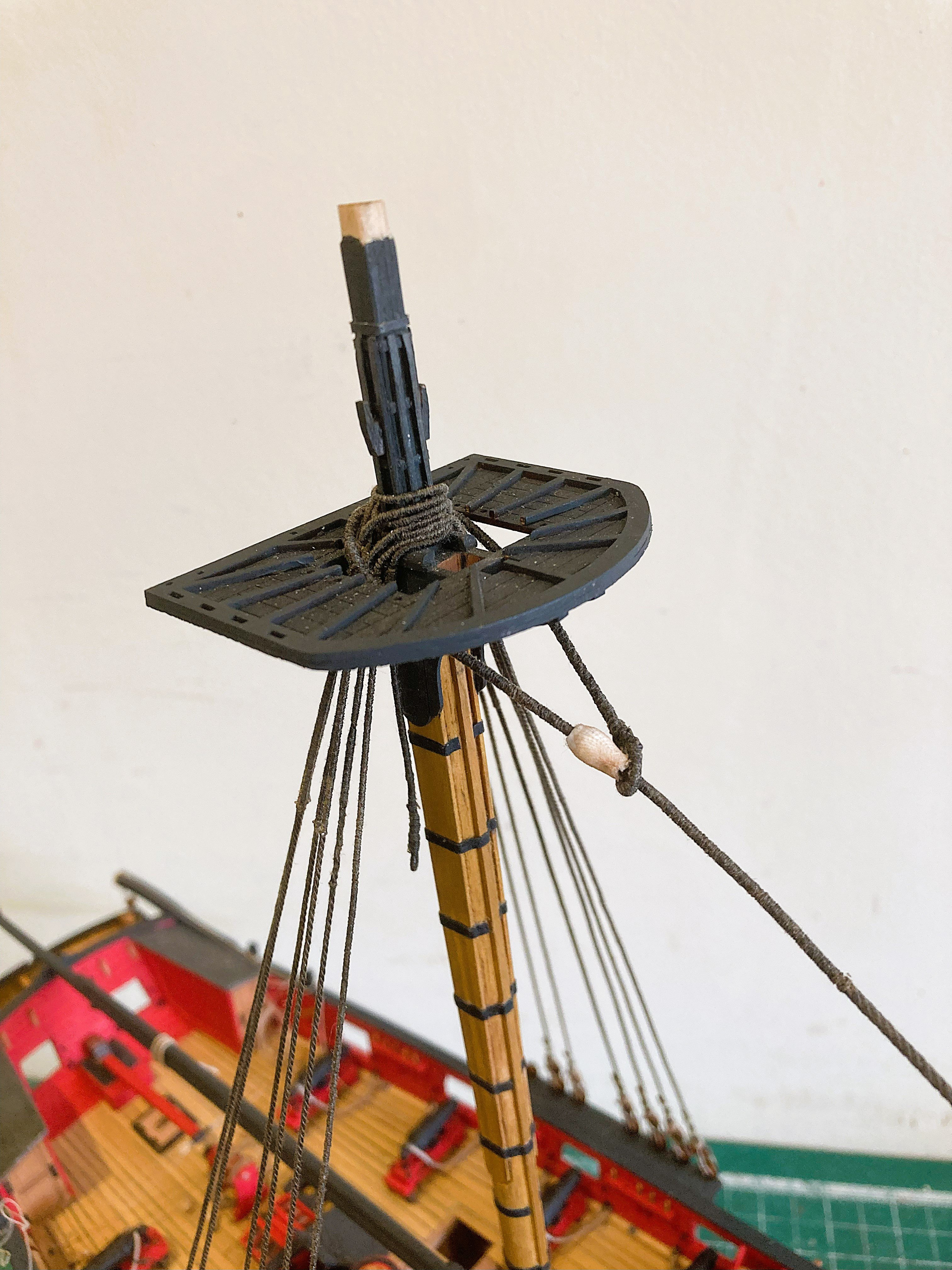
The masthead caps are fitted with eyebolts for the Toprope pendent blocks which are attached prior to fitting of the cap. The caps do not require gluing, as they are a snug fit to the masthead.

5151a

5152a
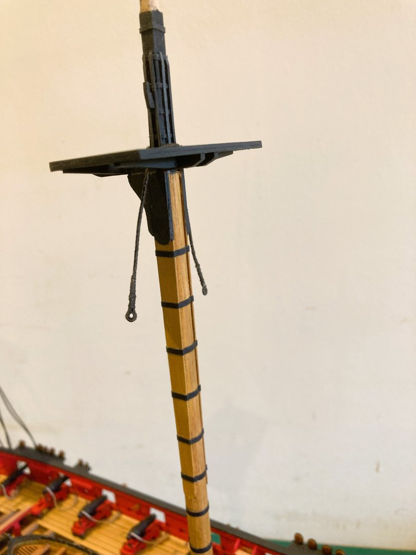
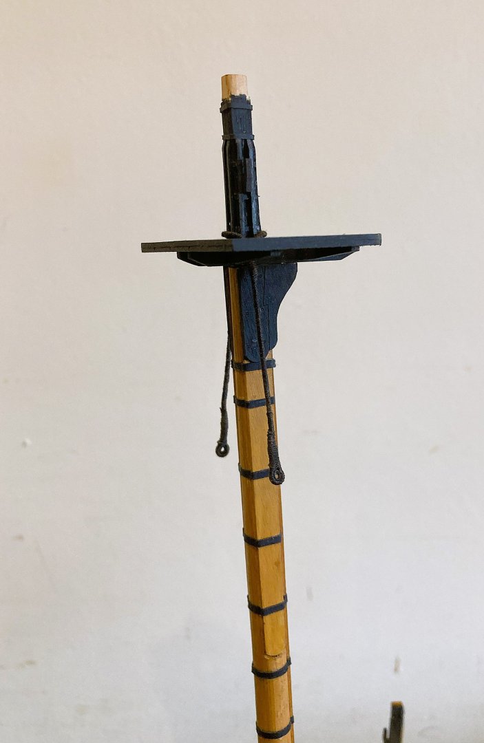
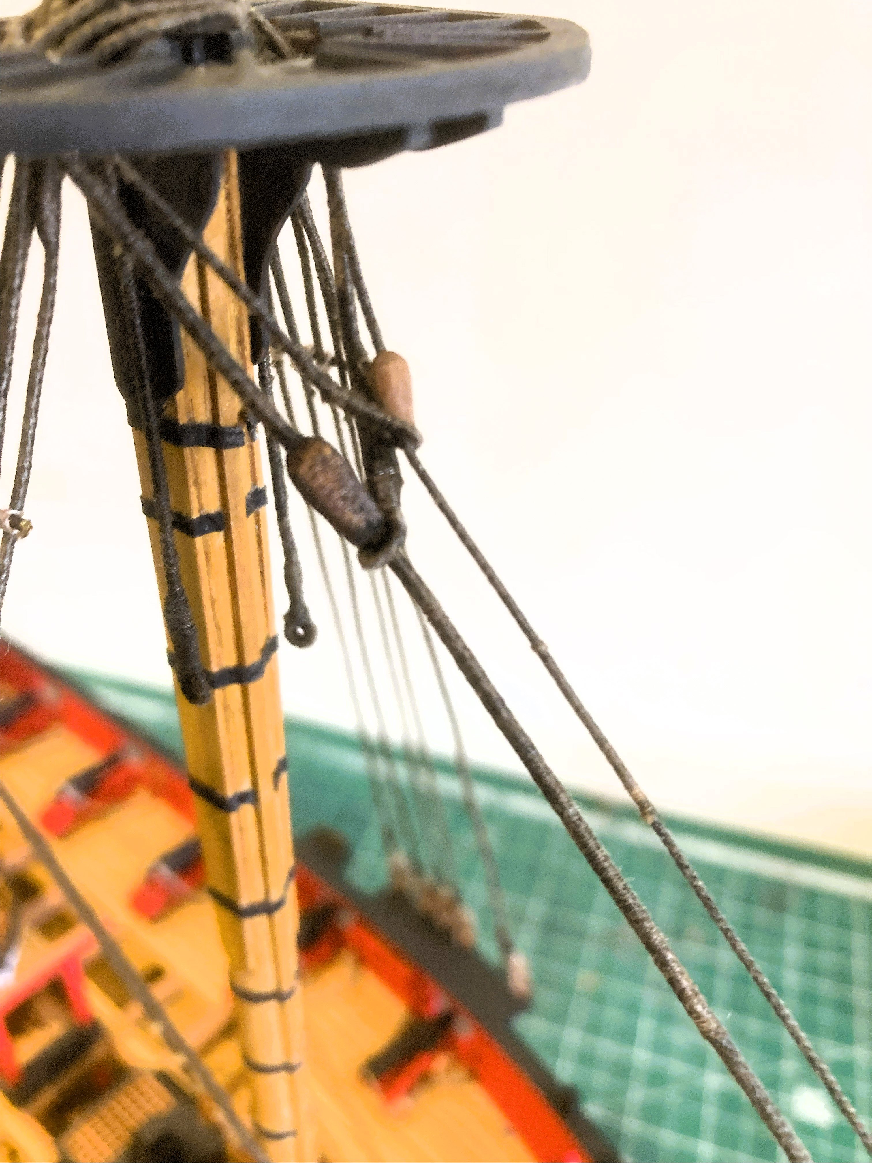
These photos shows the Standing part of the Port side lower sheave pendent, and standing and running part of the starboard side pendent.
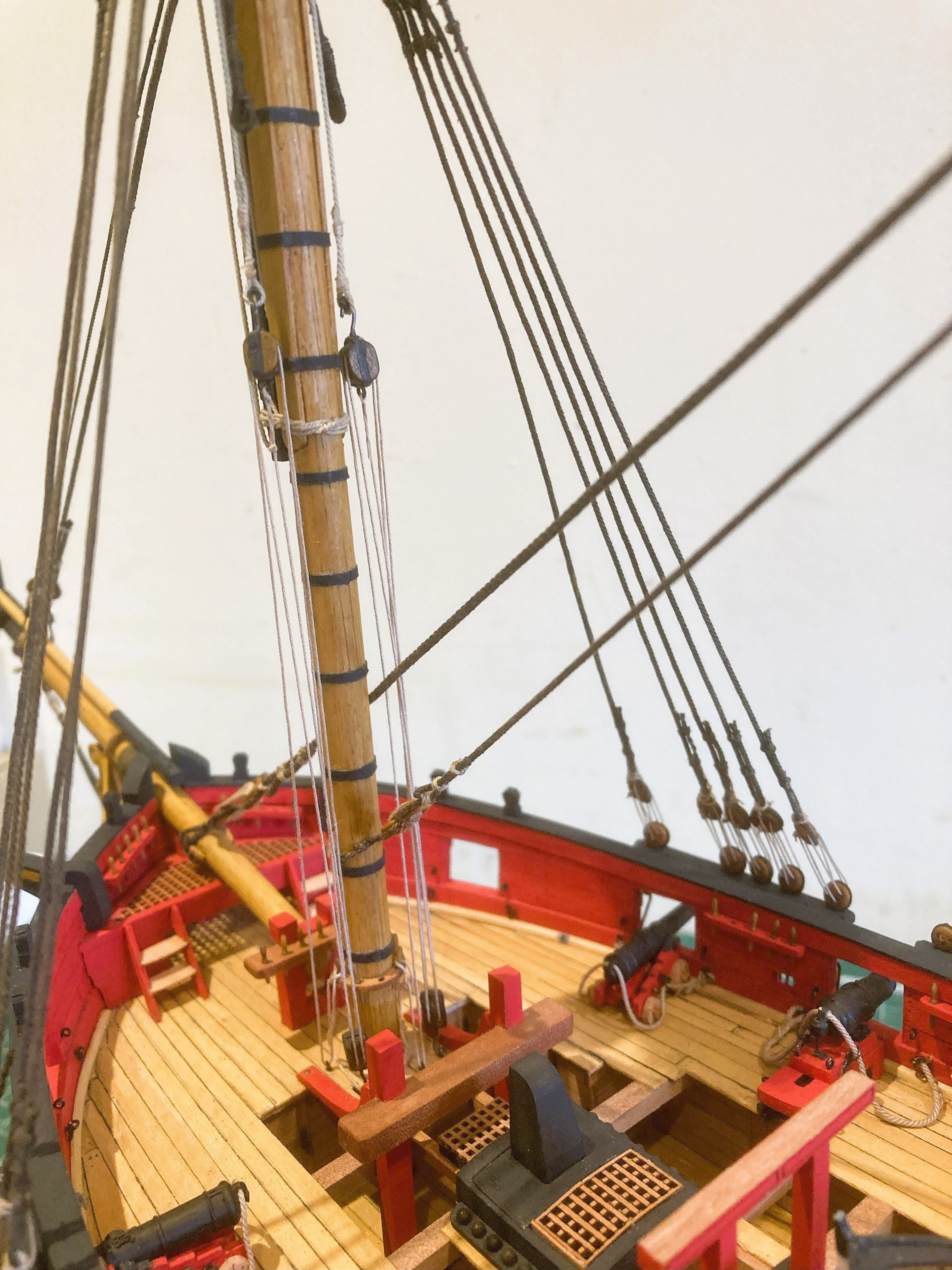
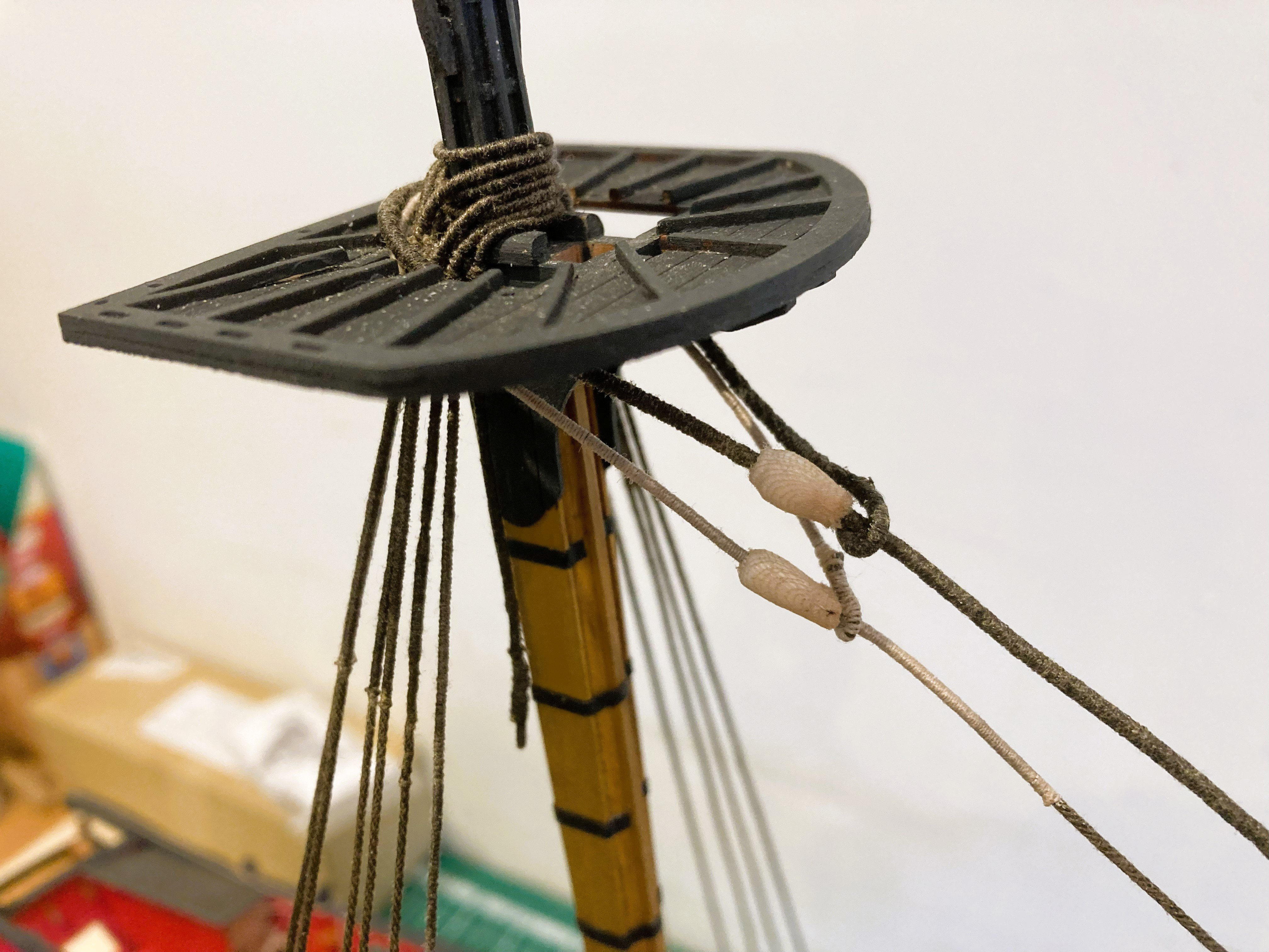
5157a
Here the Port and Starboard pendents can be seen running respectively thro’ the lower and upper mast sheaves.
The falls of the pendent are hooked to deck eyebolt aft of the mast.
A lashing is applied thro’ the fid holes to secure the Topmast.
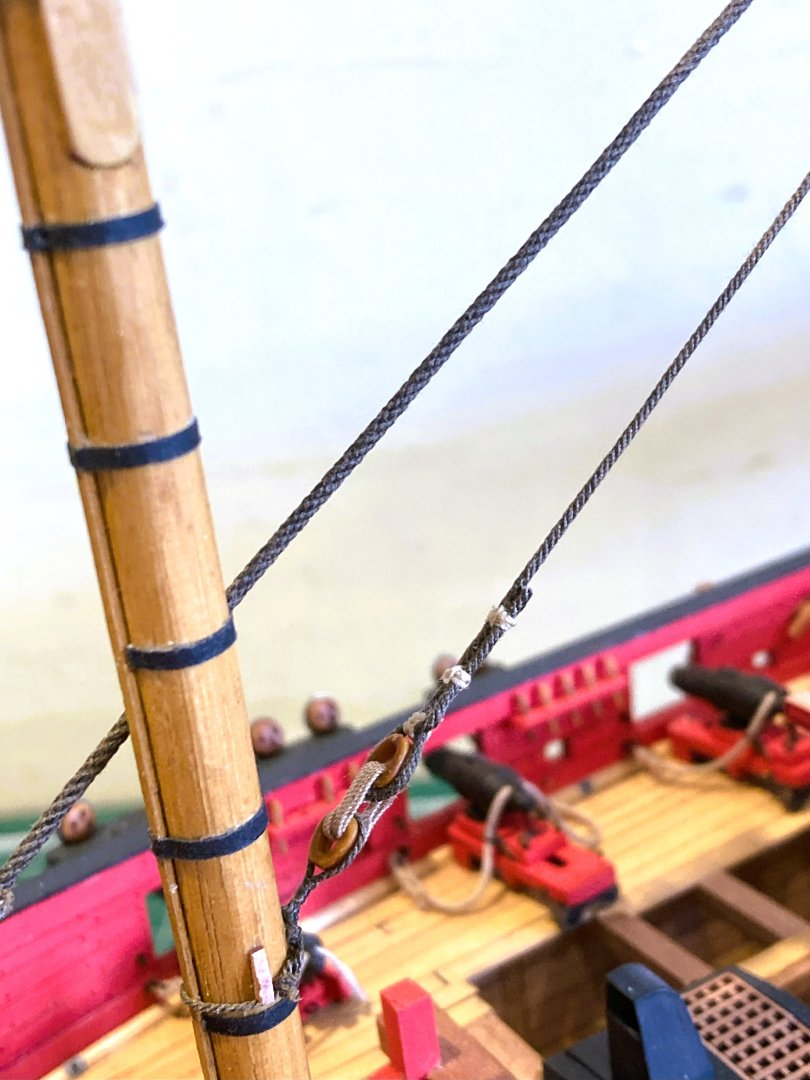
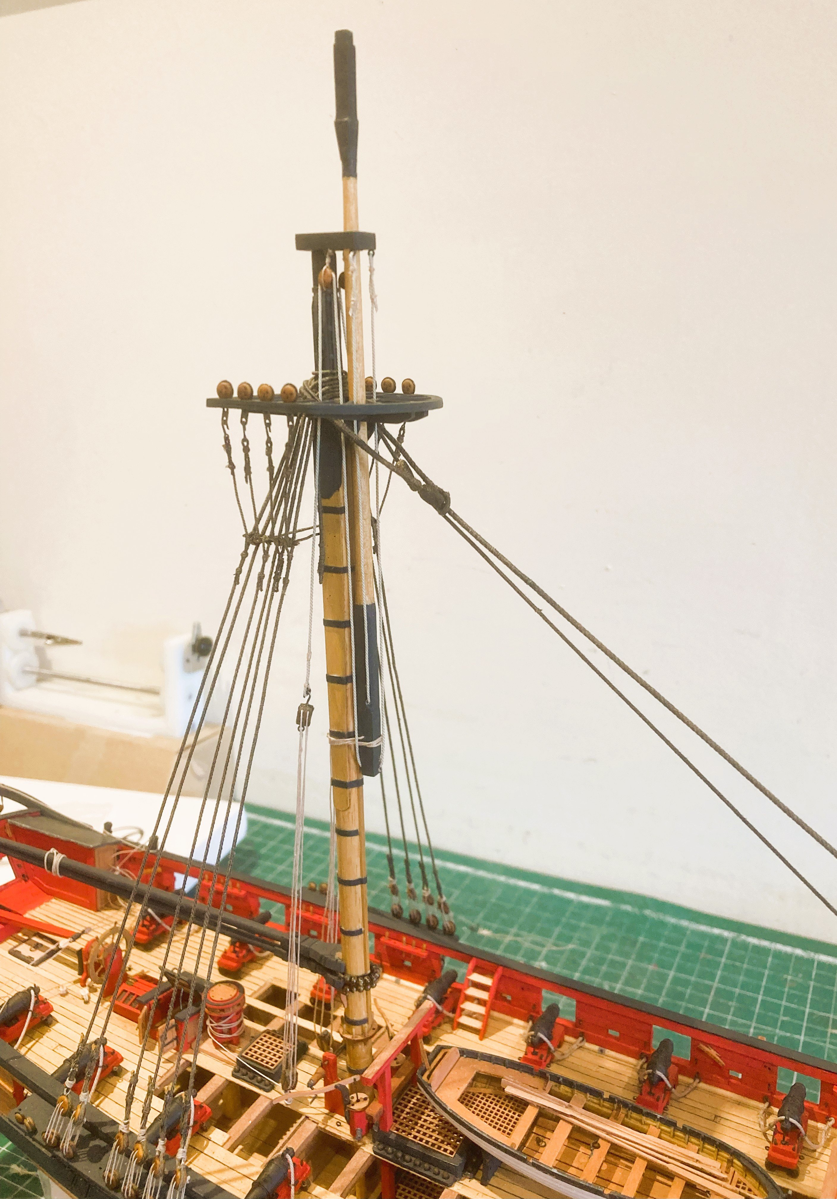
5158a
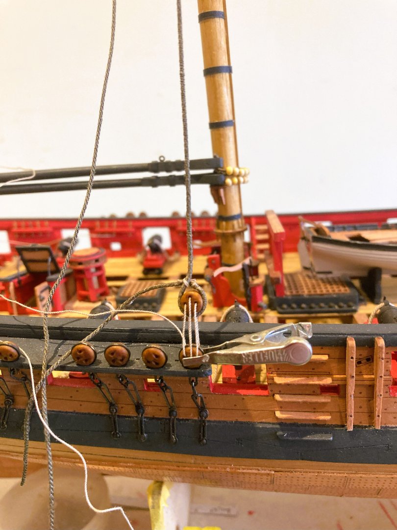
This photo shows the falls and double block tackles attached by hooks into thimble spliced to the pendent ends.

5166a
Main Topmast tackle.
Consideration has to be given to the length of the tackles to at least give the impression that in the position fixed they would raise the Topmast sufficiently for fidding.
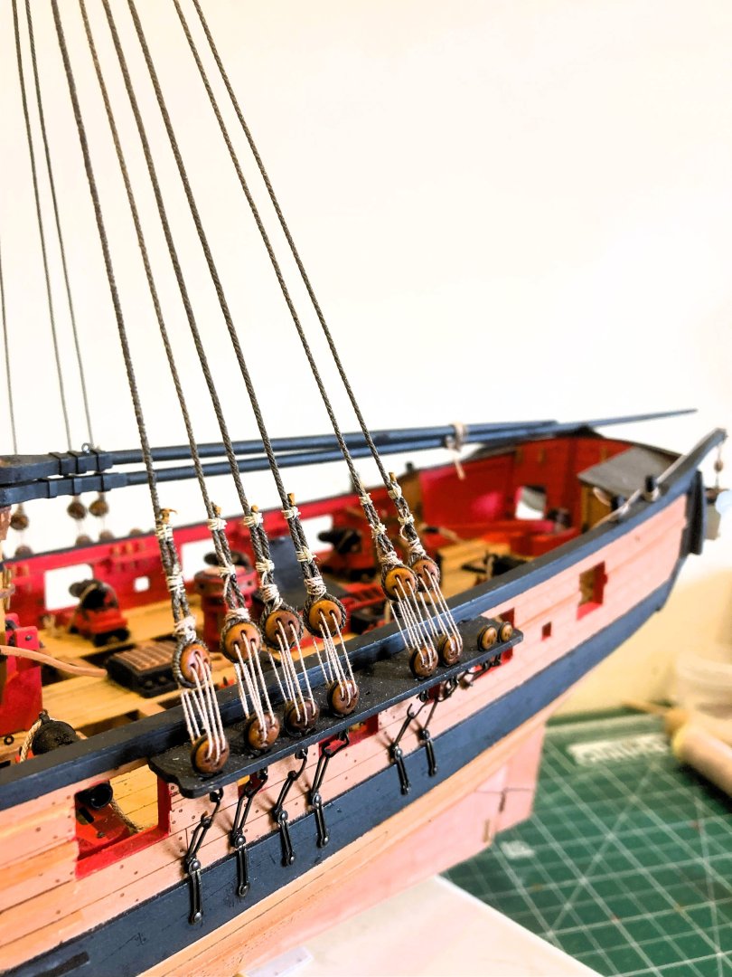
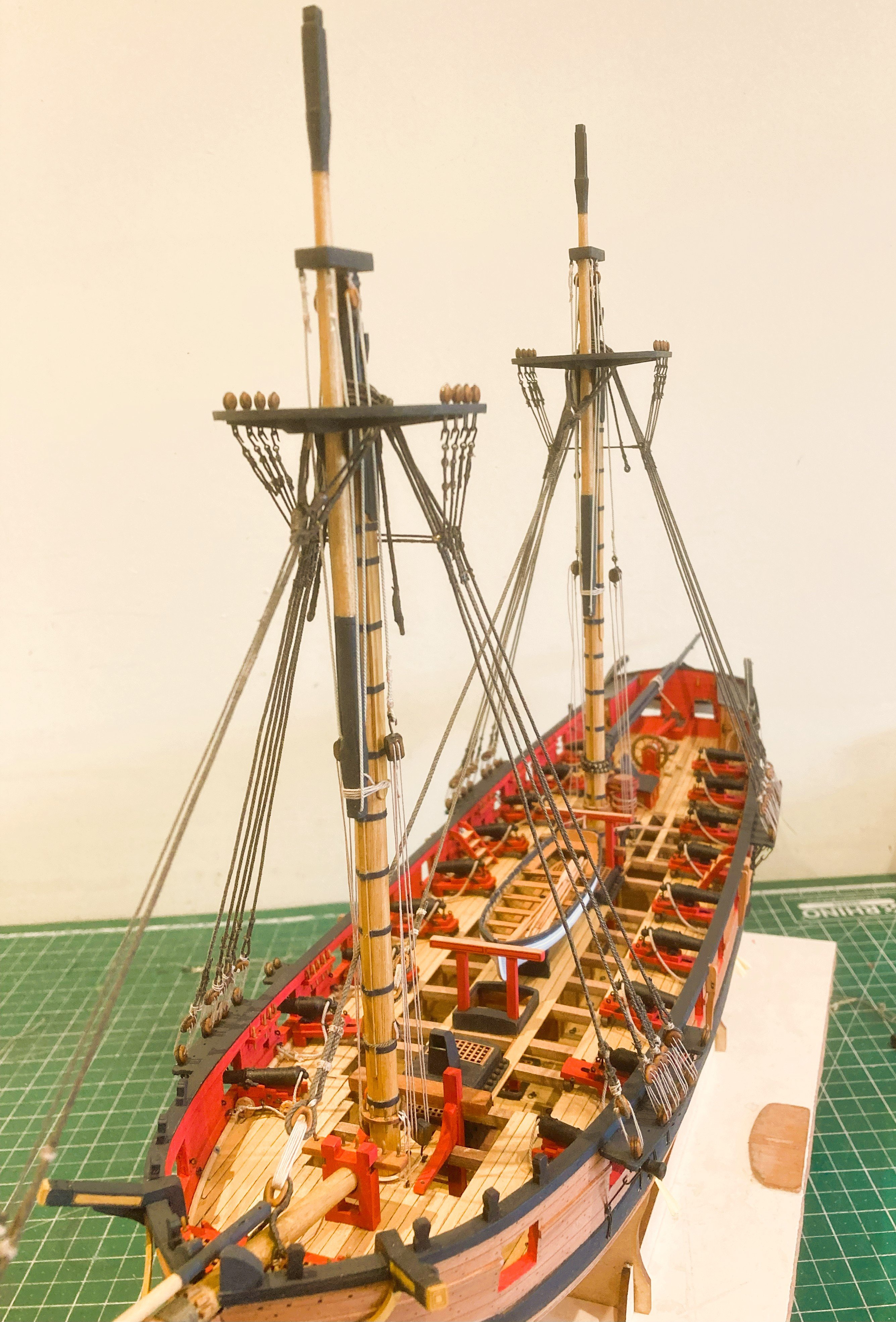
5164a
5165a
The run of the pendents through the mast sheaves.
5171a

5170a
The Topropes would not normally be seen on a model as they were generally removed once the Topmasts are in place.
B.E.
24/07/2025
-
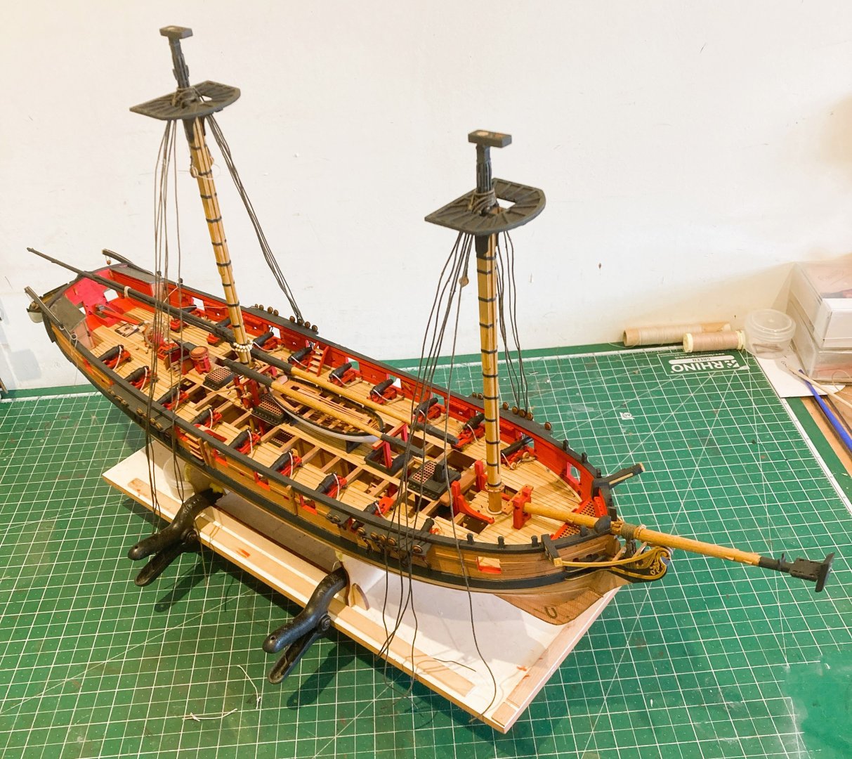
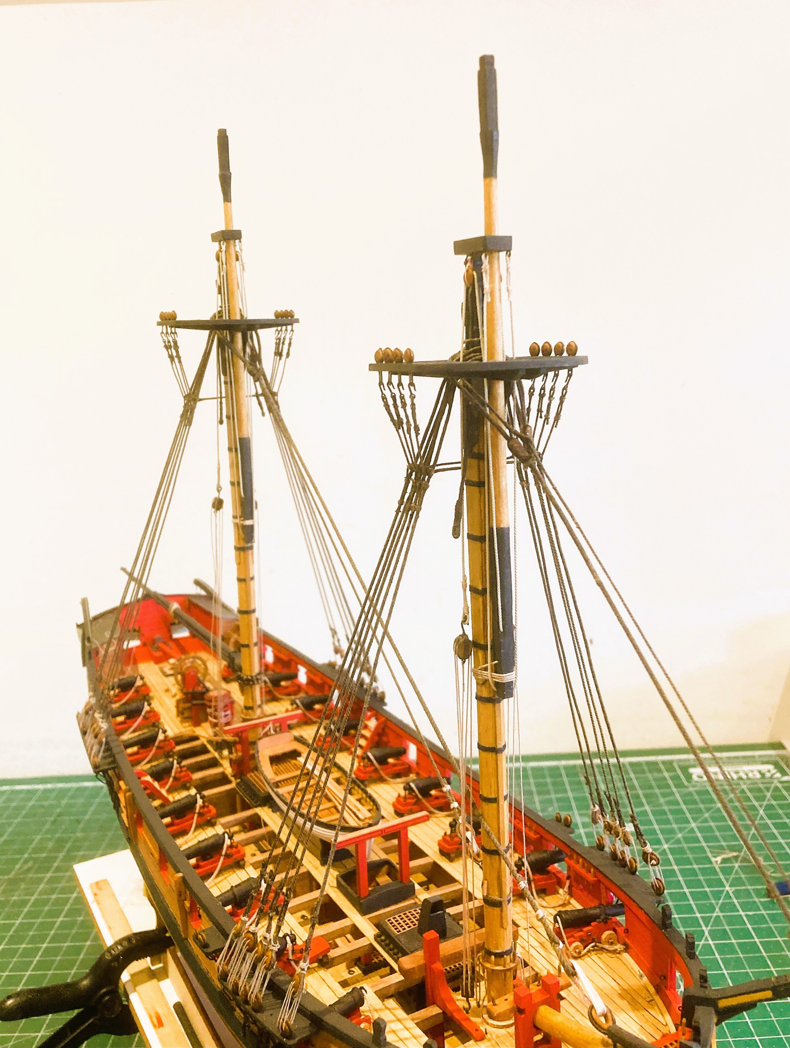
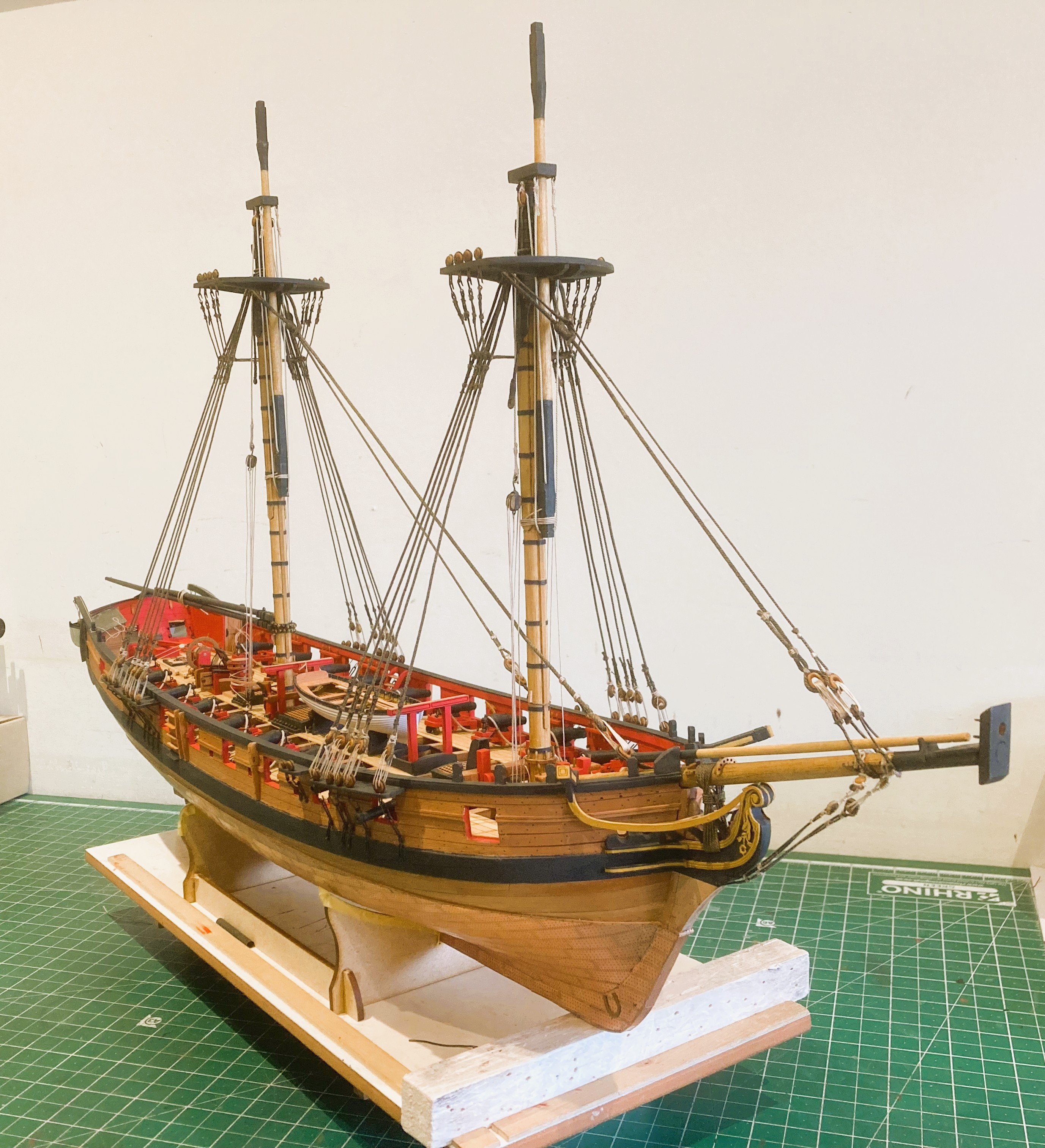
Post 100
The completion of the Futtocks at last done, with some relief I move on.
5075a

5092a
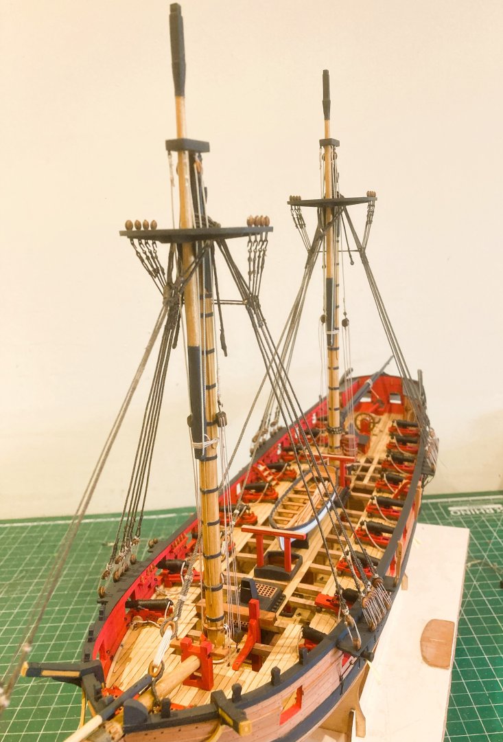
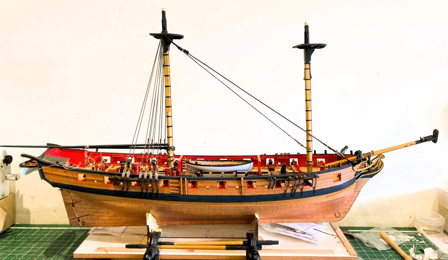
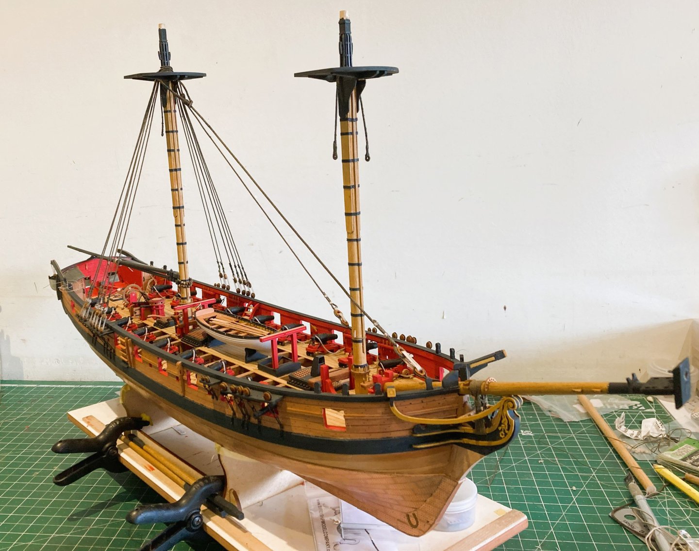
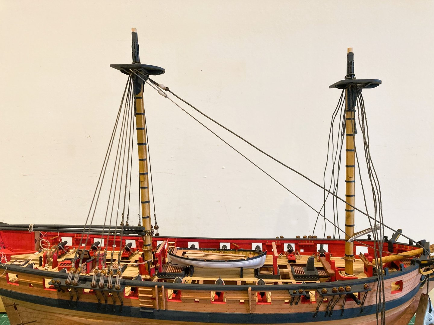
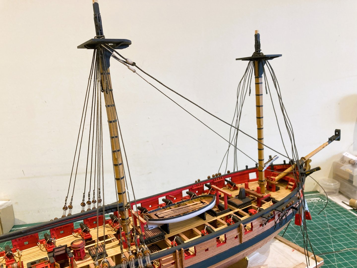
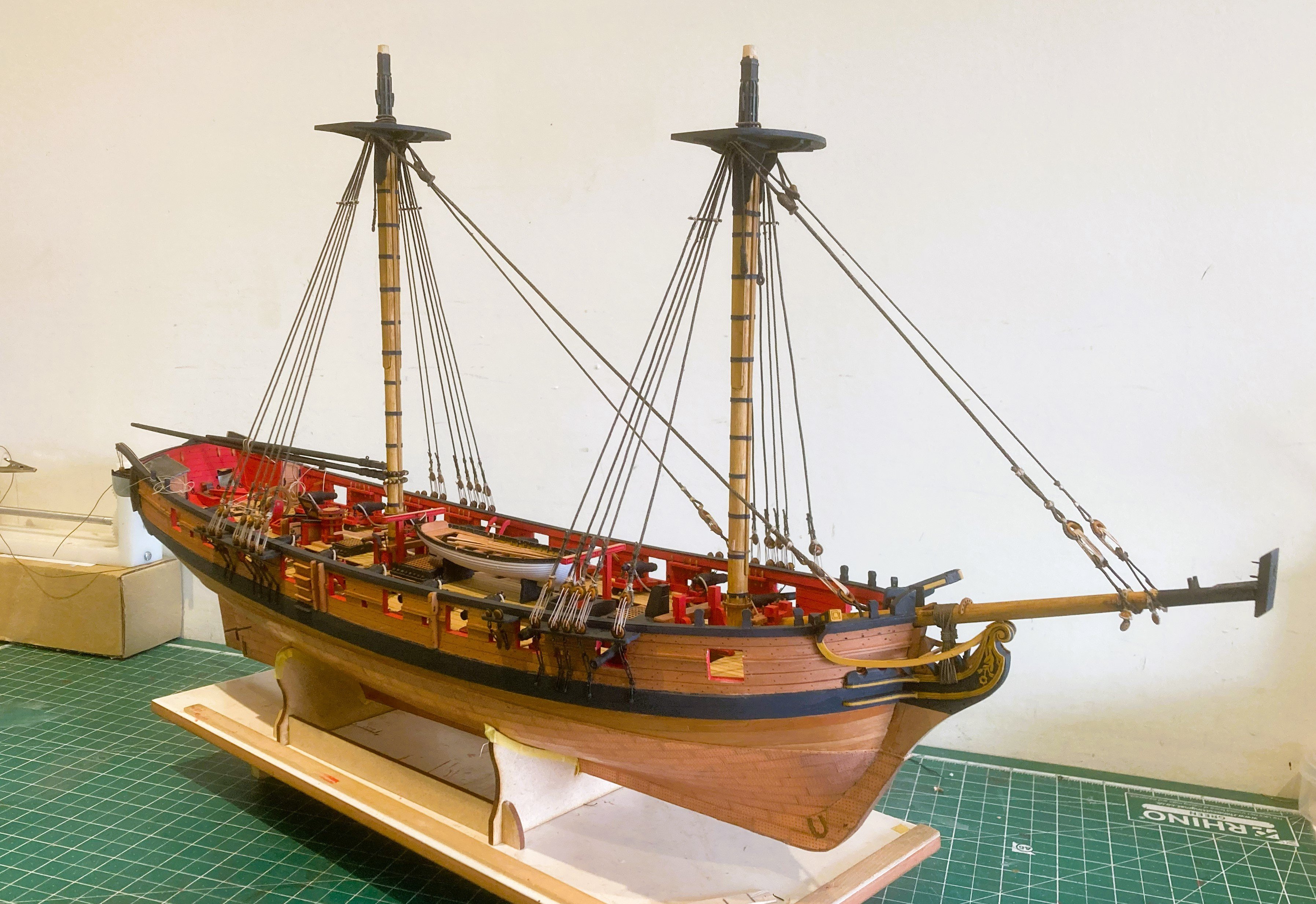
For my purposes the standing rigging has been completed bar the ‘rattin’ down.
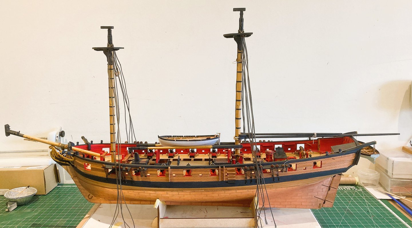
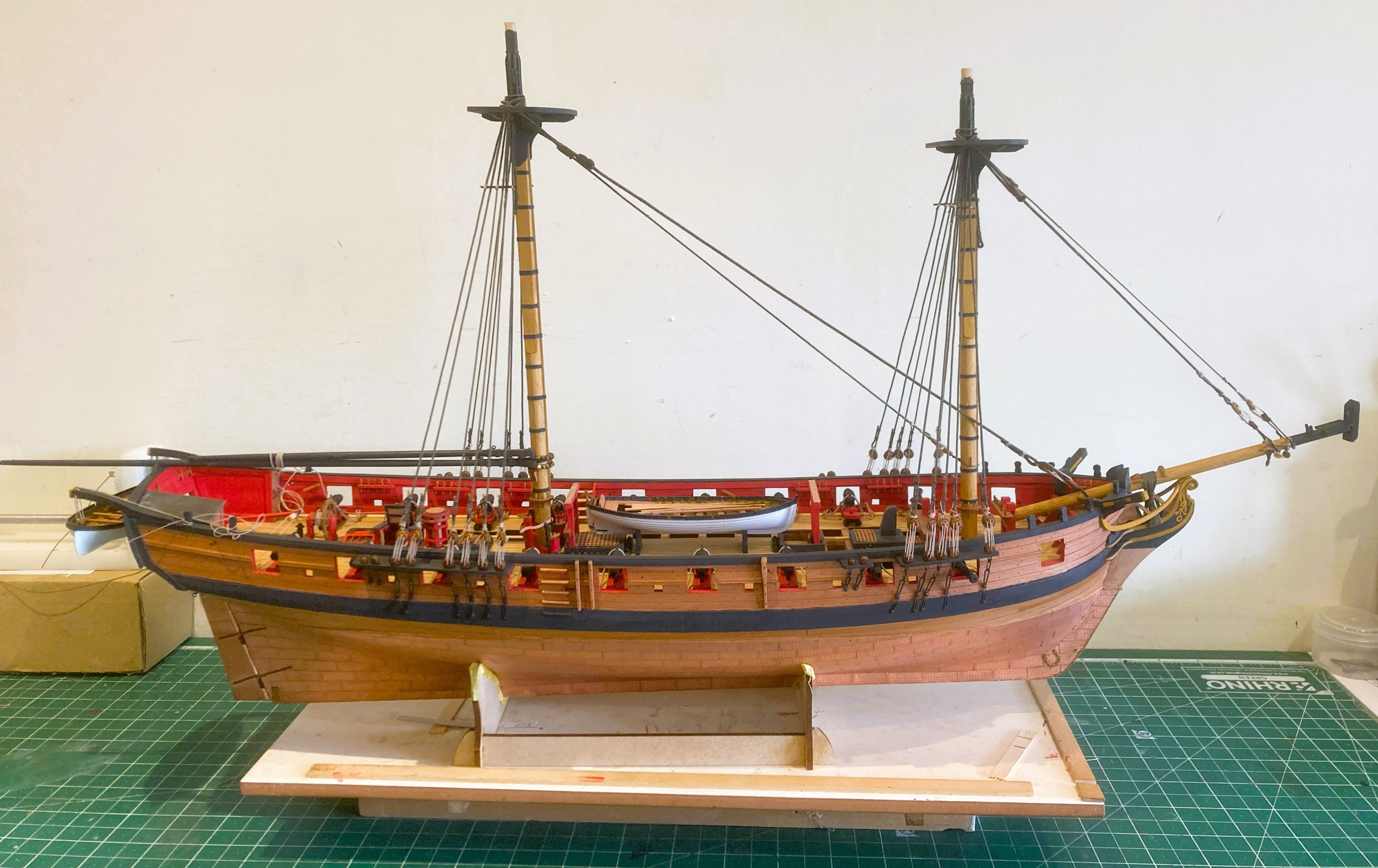
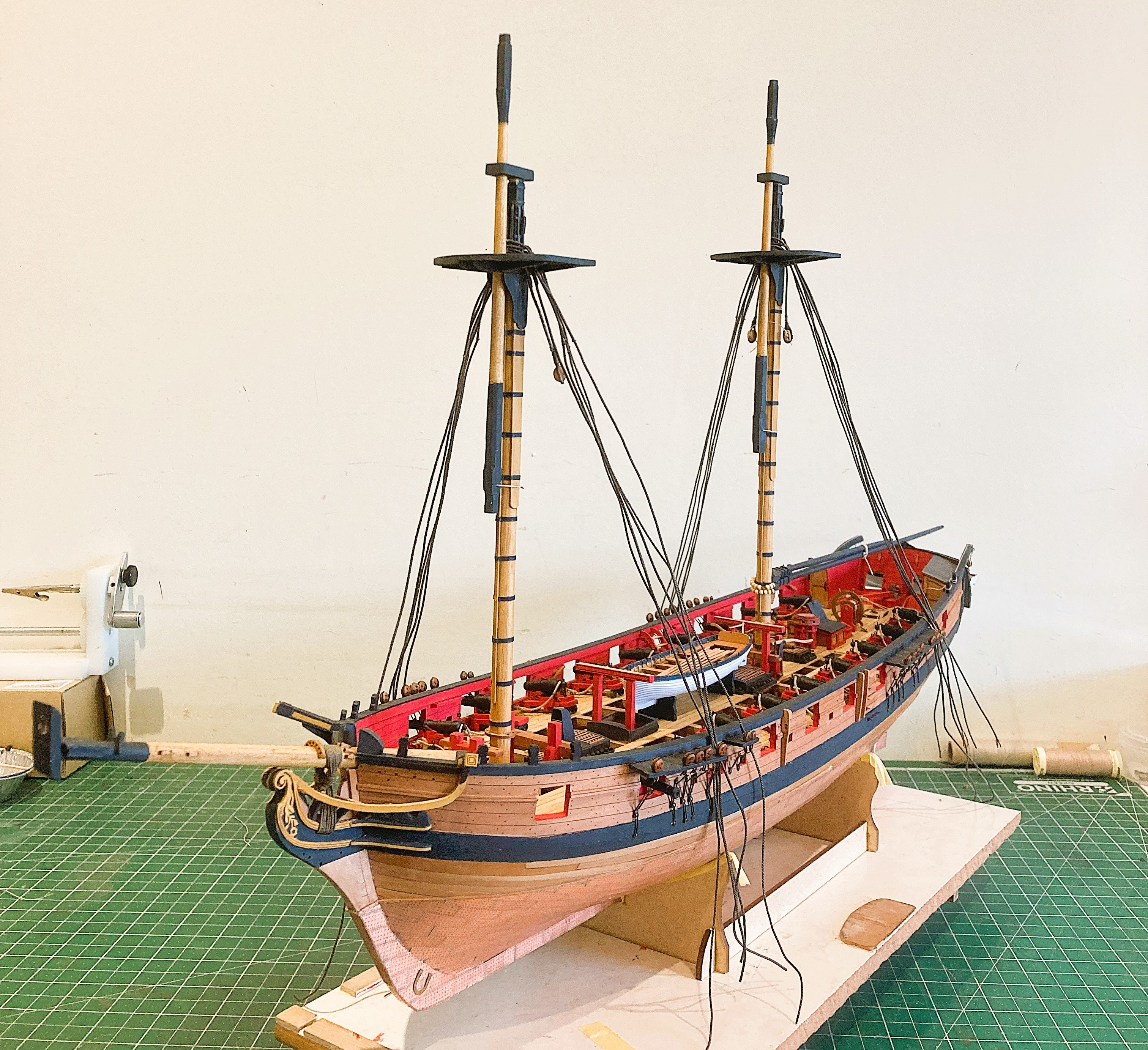
An opportune point at this eight month build stage to record the state of play.
5079a

5080a
5084a
5086a

5088a
5096a
5098a
5100a
5113a
5117a
The next stage is fitting the Top masts.
B.E.
20/17/2025
-
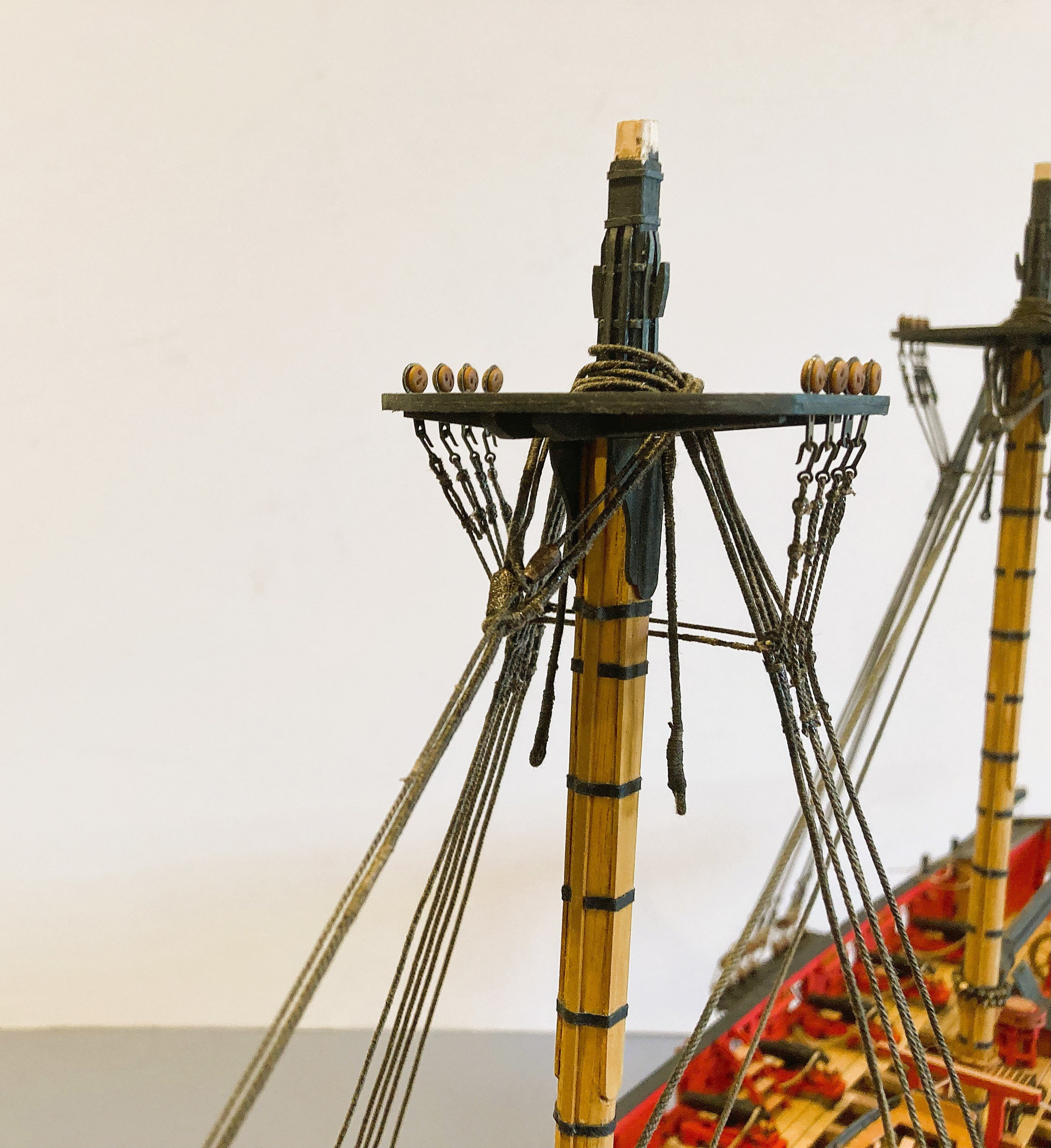
Post 99
Futtock strops and Catharpins.
By scale the topmast deadeyes are 7” – 3mm at scale.
5011a
The kit provides 3mm deadeyes(F16) which in reality are closer to 4mm, and the provided Futtock strops would be too large for true 3mm scale blocks.
I substituted Syren 4mm blocks which are a good fit for the strops.

5013a
On a visual level the kit/Syren deadeyes look better than a true 3mm would.
I blacken the strops prior to fitting the deadeyes and then re- blacken post fitting.
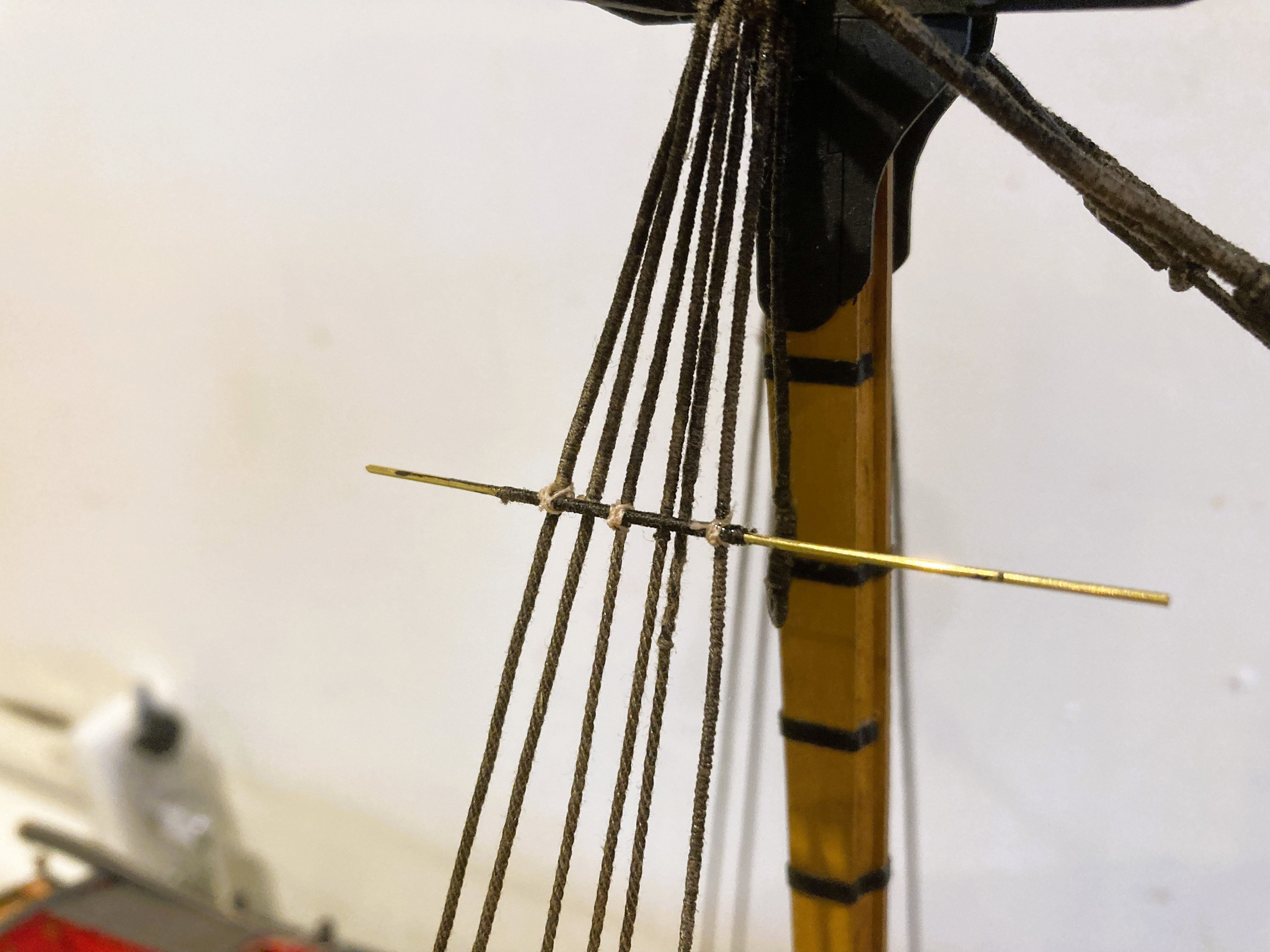
Catharpins -3½”c line – 0.44mm ø at scale.
These prevent the Futtocks pulling the shrouds out of shape, therefore they are fitted before the Futtocks.

5014a
It is far easier to make these from 0.5mm brass wire served with line. An eye formed at each end makes fitting fairly straightforward.
5031a
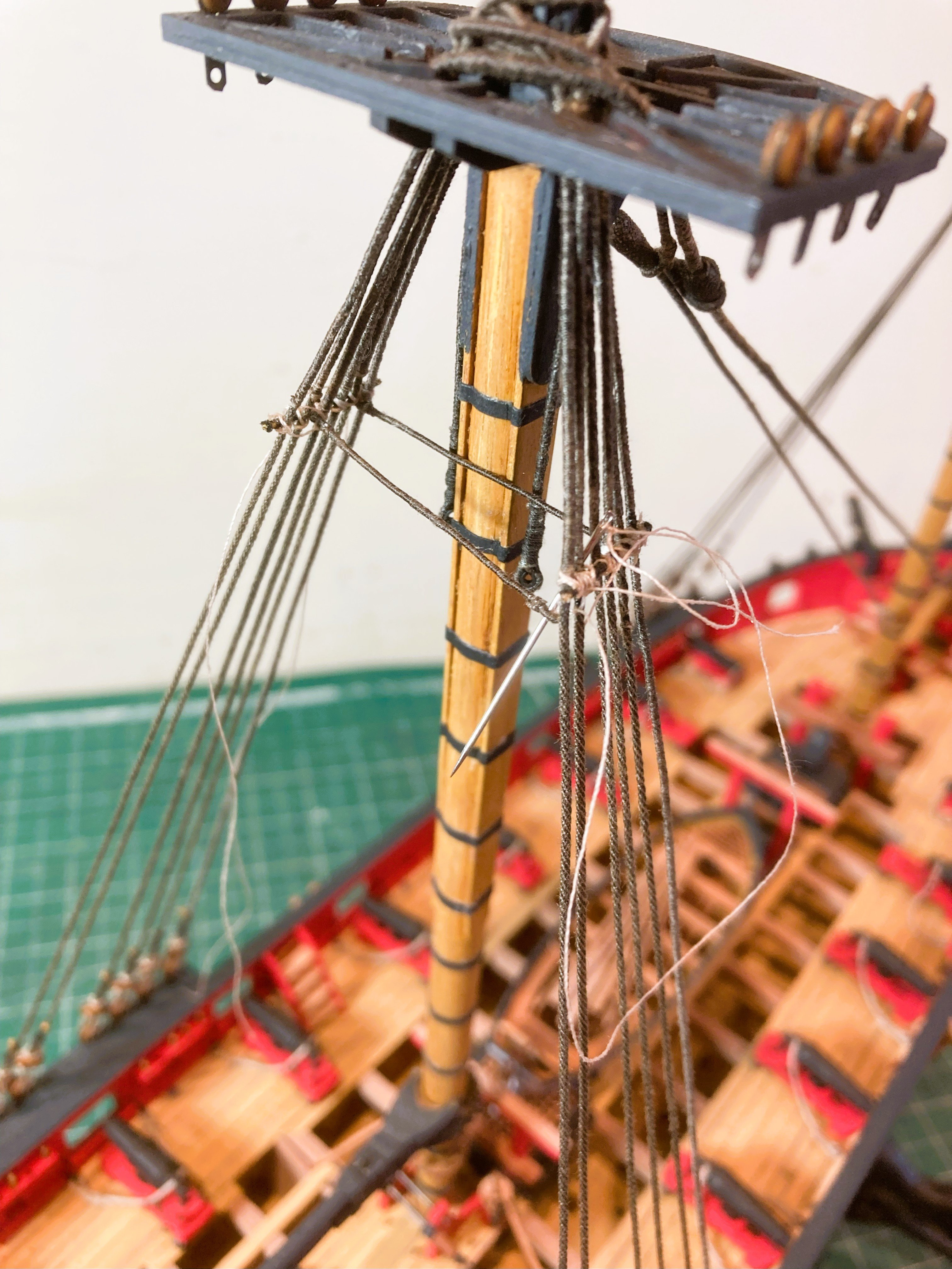
I say straightforward but they are quite fiddly to make and serve, and use of a needle to do the fitting certainly helps.
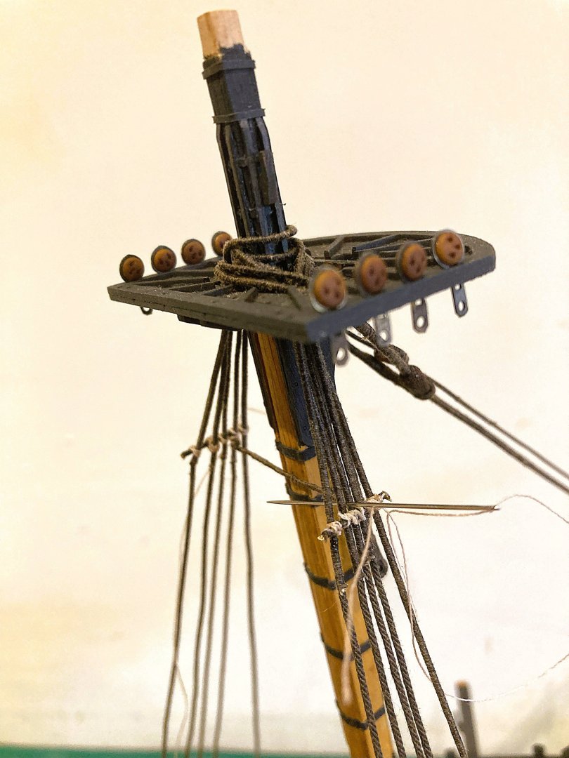
5028a

5034a
Usually there were four Catharpin legs per mast but the kit plan indicates only two.
5035a
Looking at the model it would prove quite tricky to fit a set of four in the available space, so thankfully I’ll move swiftly on…
Fore and Main Futtock shrouds
From Steel
Futtocks 4½”c line - 0.56mm ø at scale.
I am using Syren 0.63mm ø line.

5049a
My approach is to firstly attach the line to the lower shrouds below the stave and then tauten the line thro' the hook eye whilst attached to the futtock strap. The line is then seized.
Care is required to avoid pulling the shrouds out of line.

5042a

5054a
I am using the kit supplied Gütermann line for the seizings. They will be blackened once completed.
5051a
5055a
There is no doubt that rigging the Futtocks is a tiresome business with a set of four round seizings to each one.
Onto the Starboard side…
B.E.
17/07/2024
- eatcrow2, Desertanimal, Rustyj and 22 others
-
25
-
-
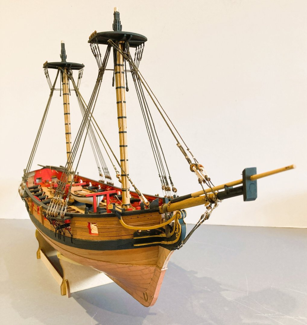
Post 98
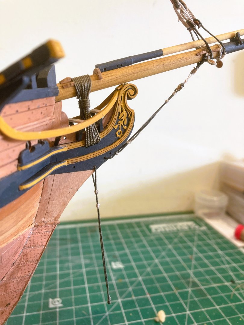
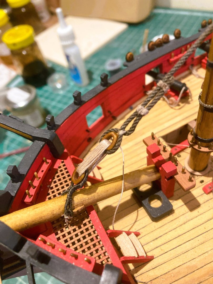
Bobstay and Bowsprit shroud fittings
I have decided to add these because the strops are fitted against the stops before those of the Fore Stays. The Bobstays will also be fitted.
The kit indicates the use of 3mm deadeyes to secure the Bobstays and Bowsprit shrouds which is an acceptable alternative to hearts.
As the smallest hearts I have are 5mm, a tad on the large side, and as I have no appetite to make tiny 3mm hearts, I go with deadeyes of which I have a supply of the Syren 3mm resin versions.
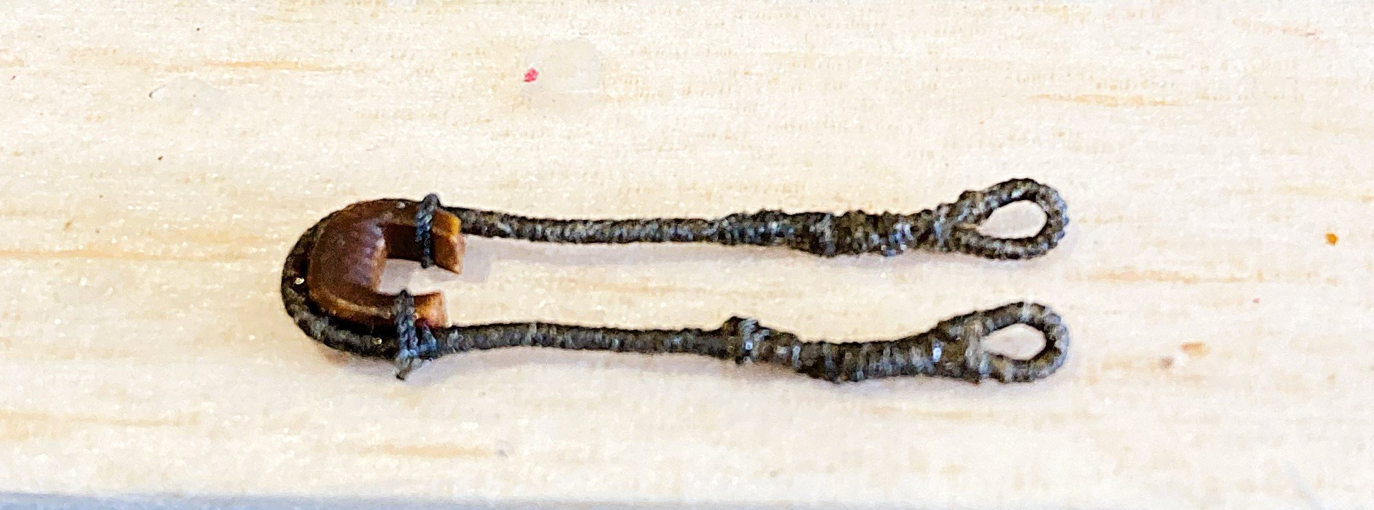
Bobstays

4993a
These are quite tricky to represent authentically, as they involve served line passing through a hole in the Knee of the head before being spliced to itself, with a Deadeye or heart seized in its bight,with the splice sitting in the top groove of the Deadeye/heart. The now double line is seized together below the deadeye/heart and above the knee of the head.

4997a
You sometimes have to get inventive to hold the lines taut for seizing.
4995a
5001a
The 3mm deadeyes are tiny things to secure within the served line and look a little overwhelmed in the bight.
They also don’t take the 0.30mm line which is the correct scale size for the lanyards.
I used 0.1mm line as per the kit plans, but which seems very under size for these important stays.
I’m not entirely happy with these and may revisit using slightly larger hearts and lanyards.
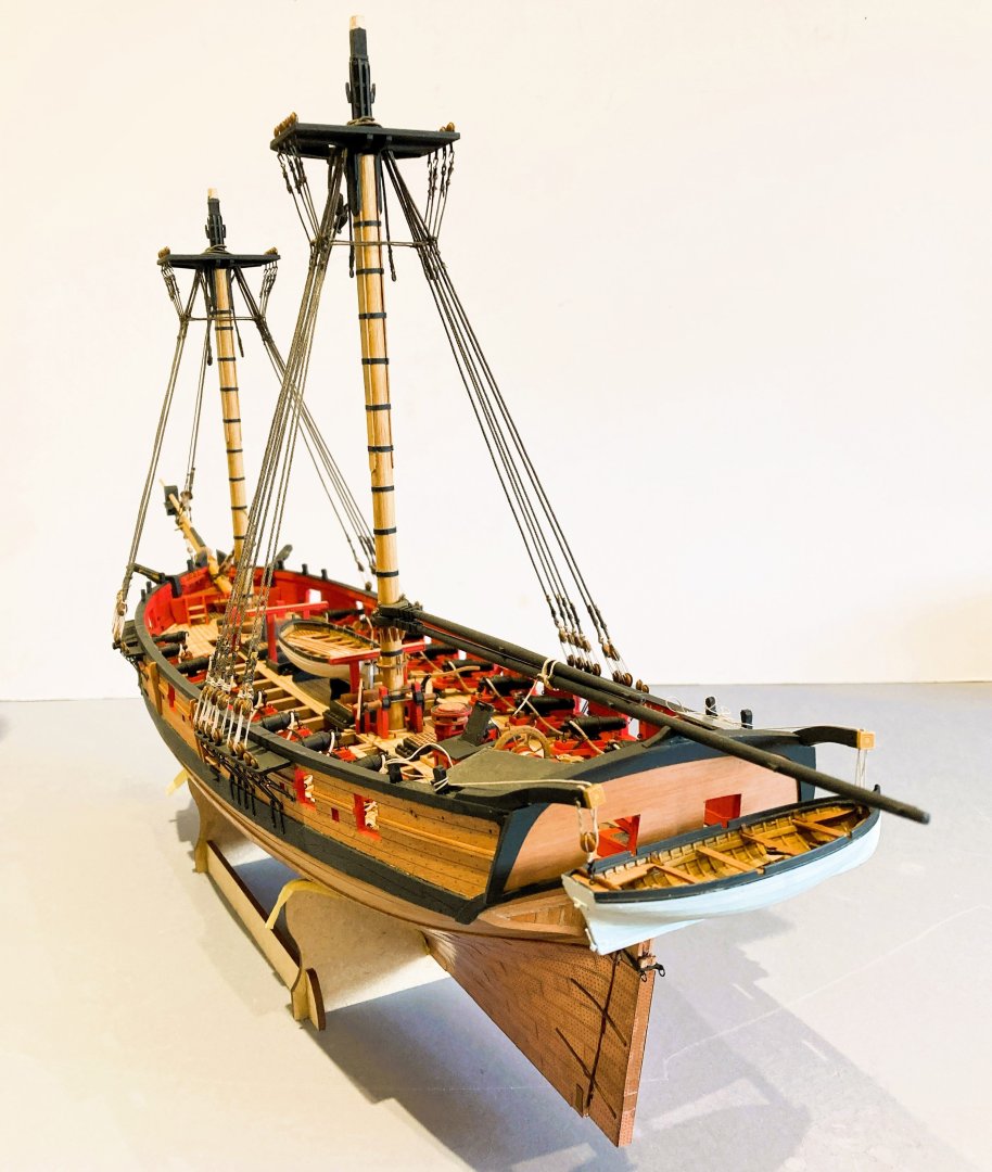
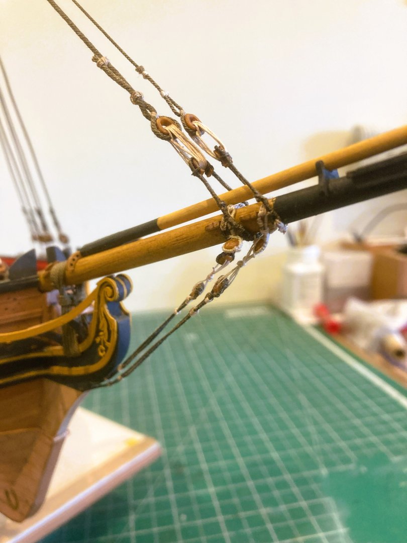
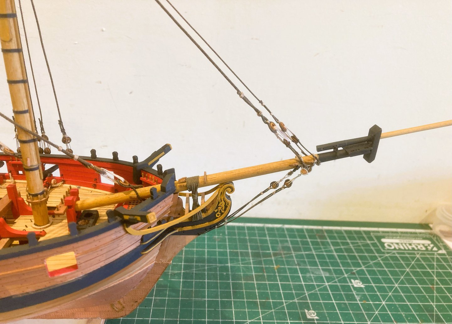
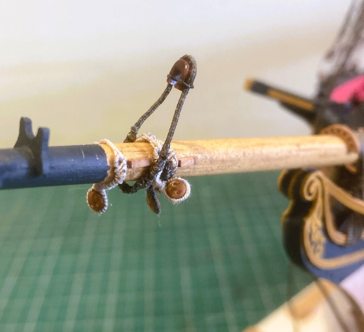
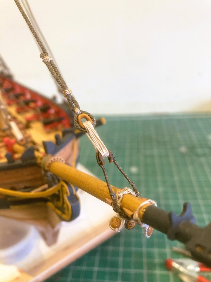
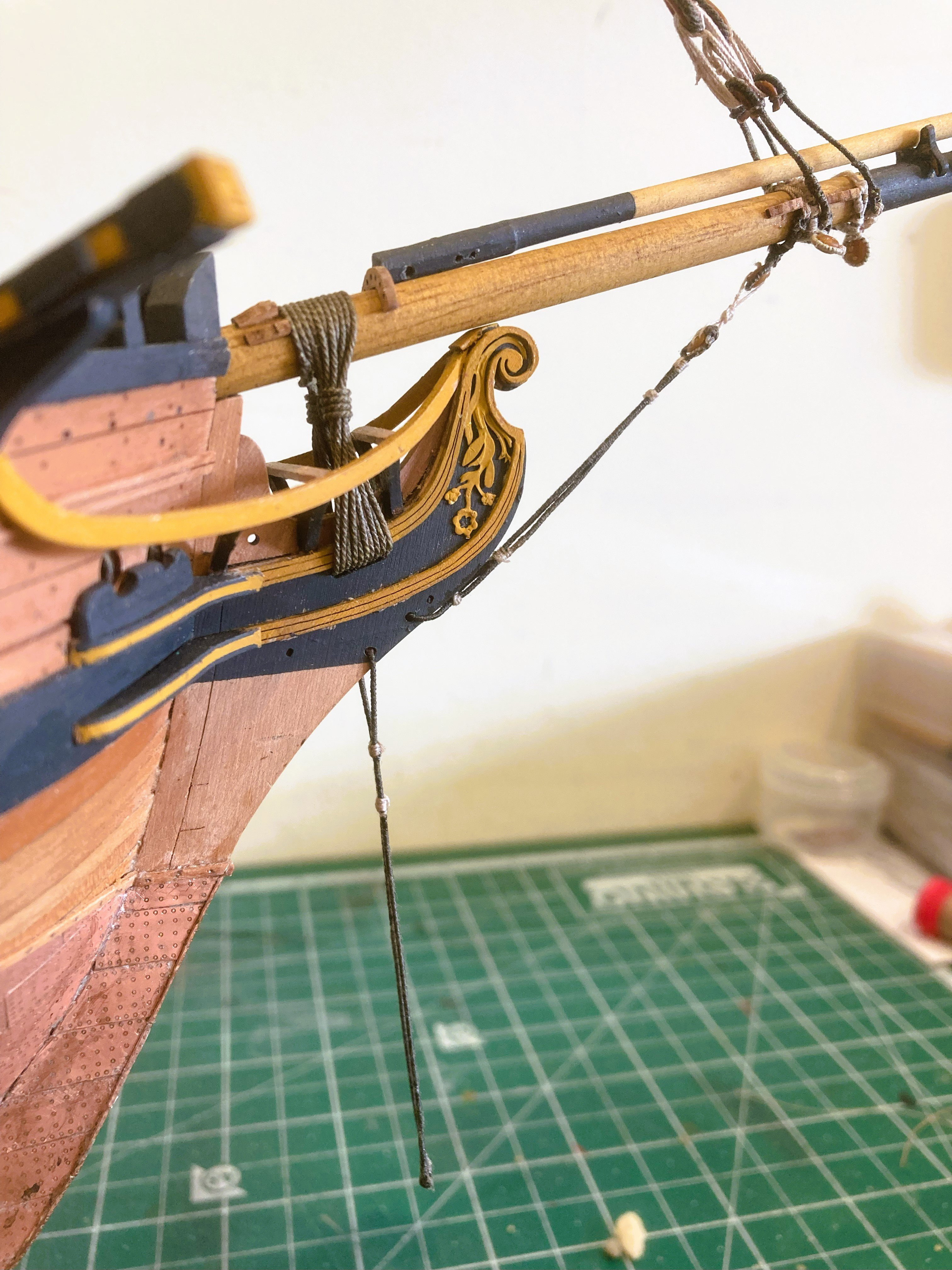
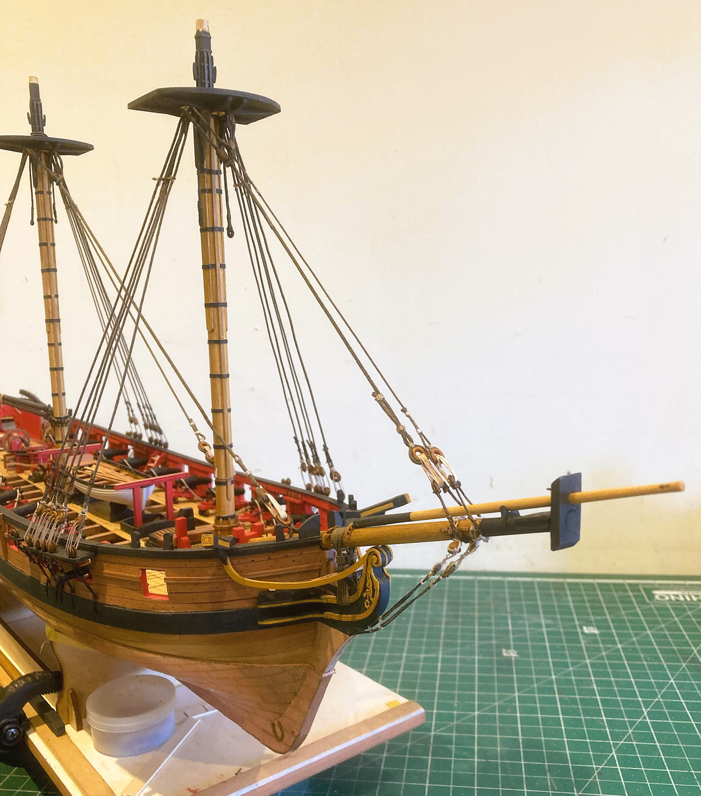
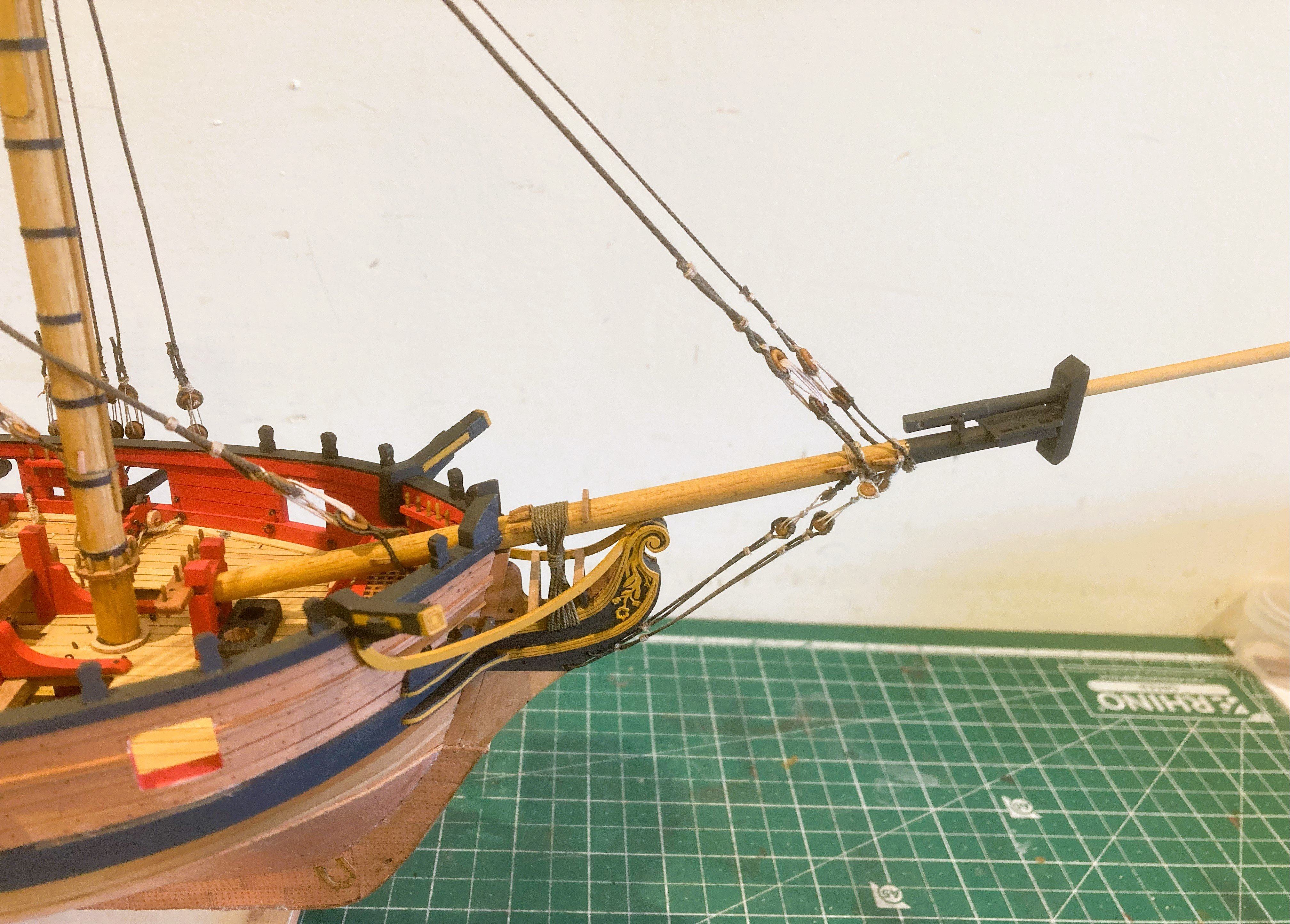
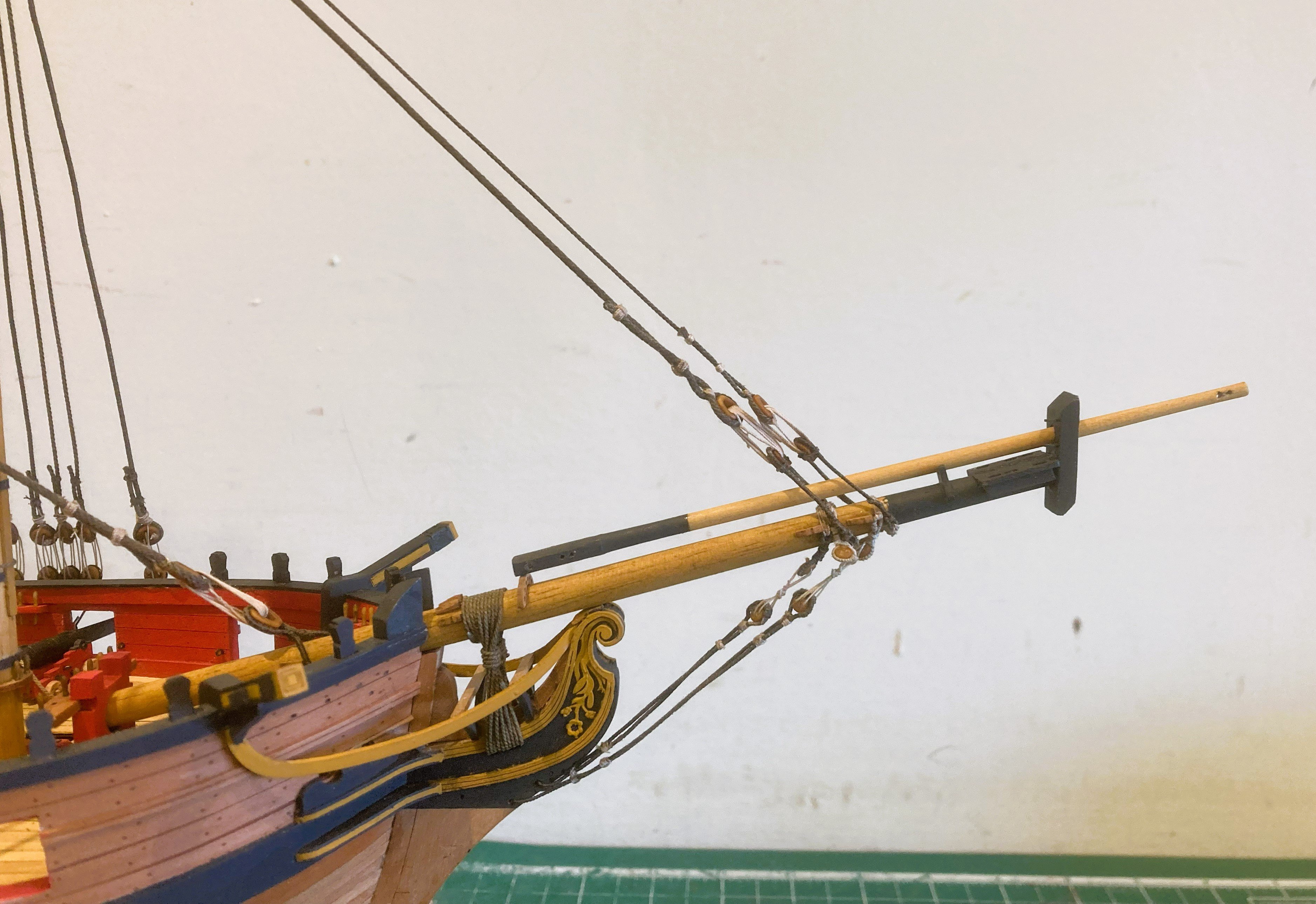
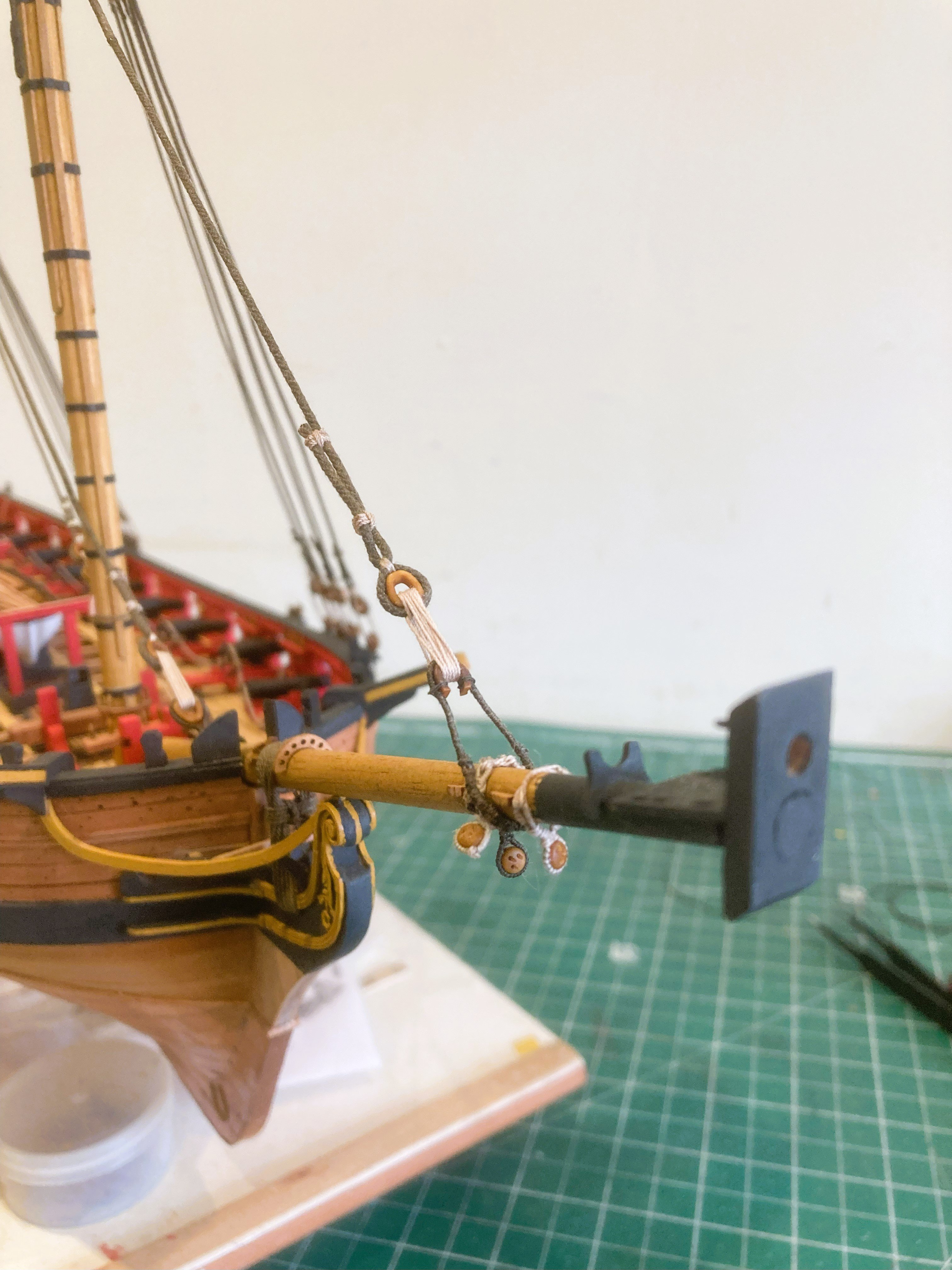
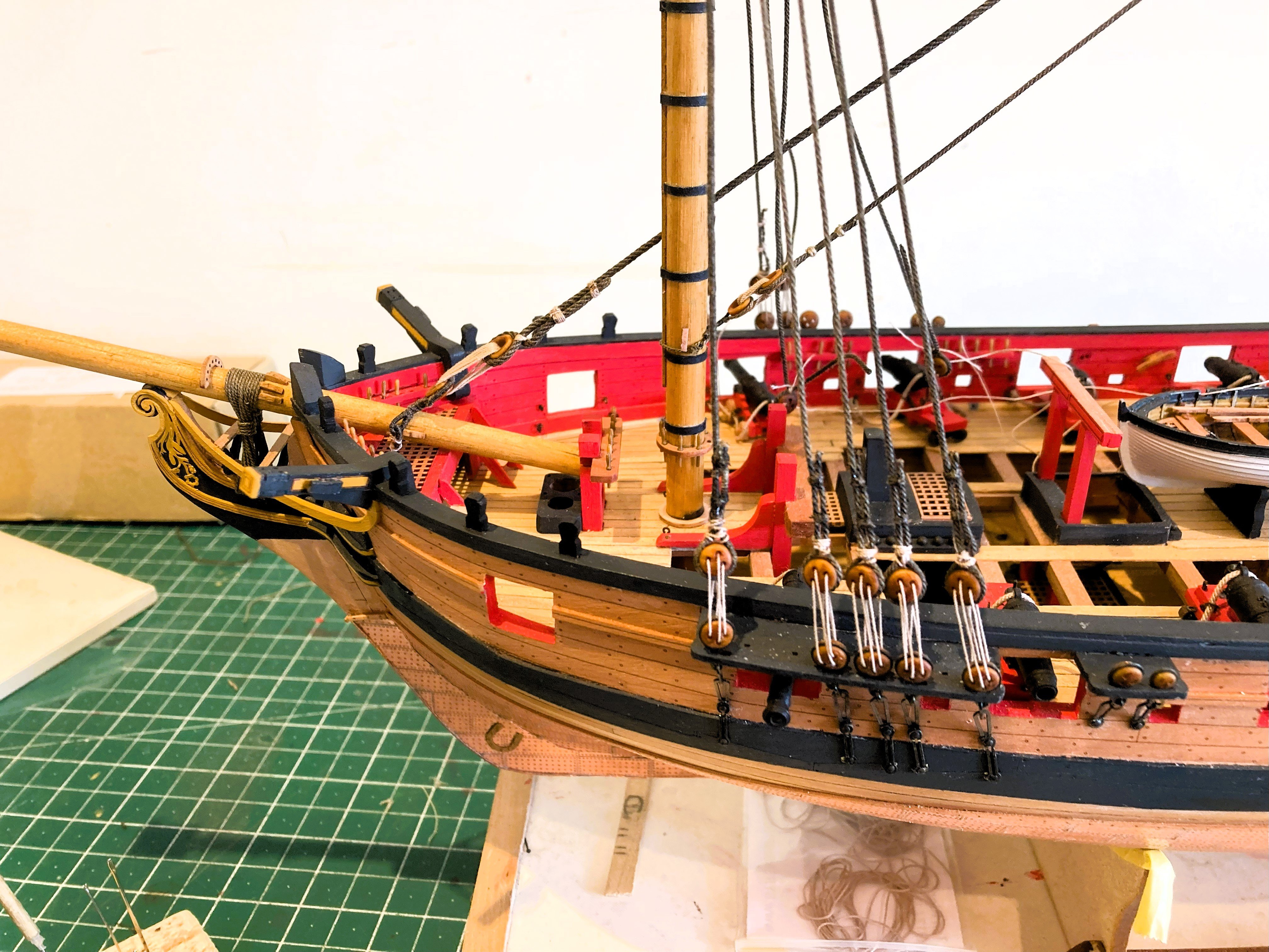
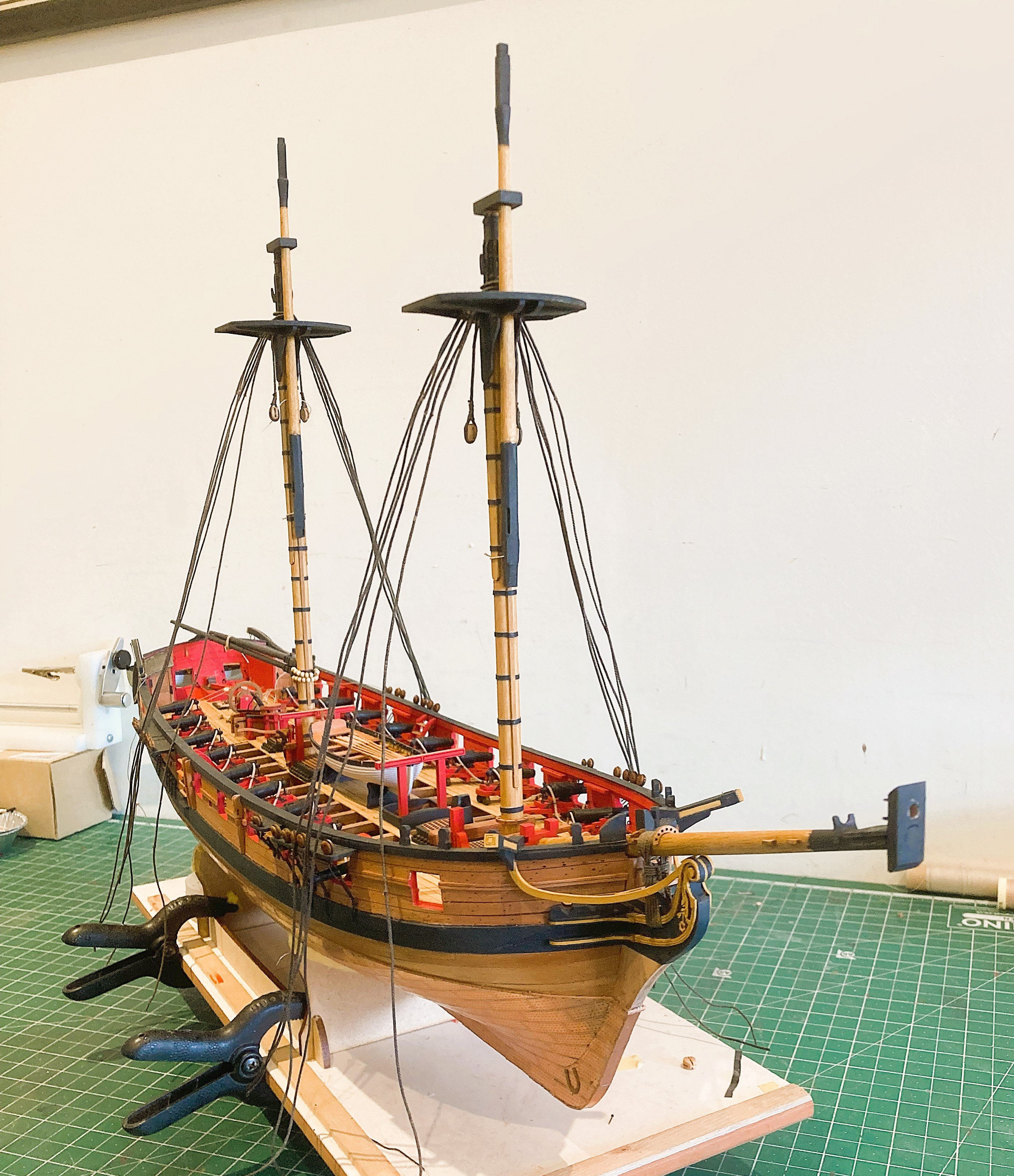
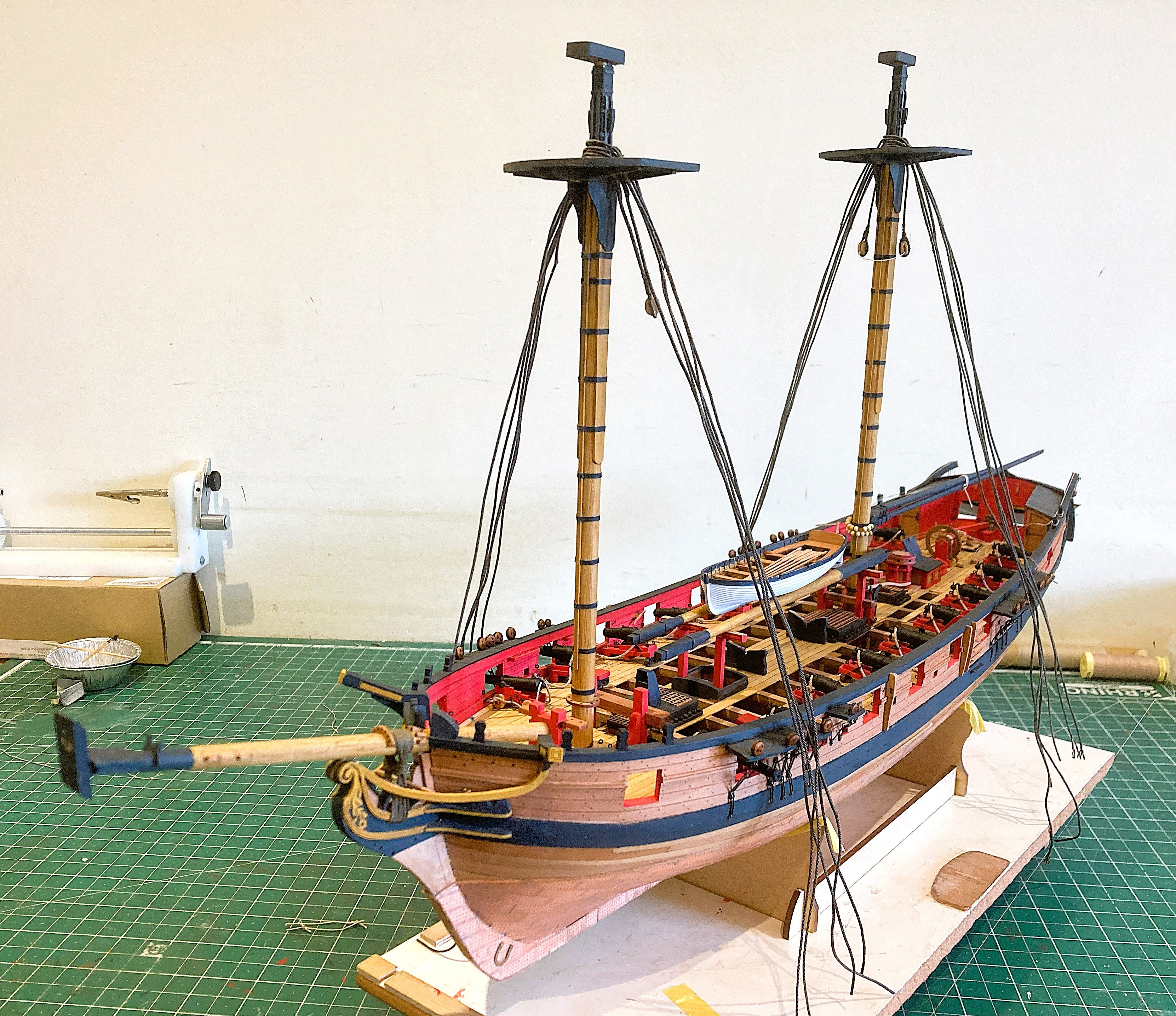
Jib boom
I have decided to include the Jib boom albeit in the inboard position. This allows fitting with a minimal increase in the overall size of the model.
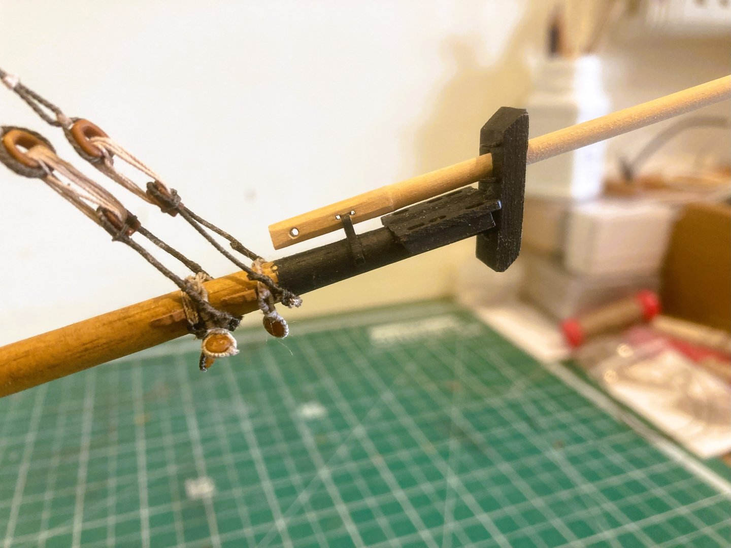
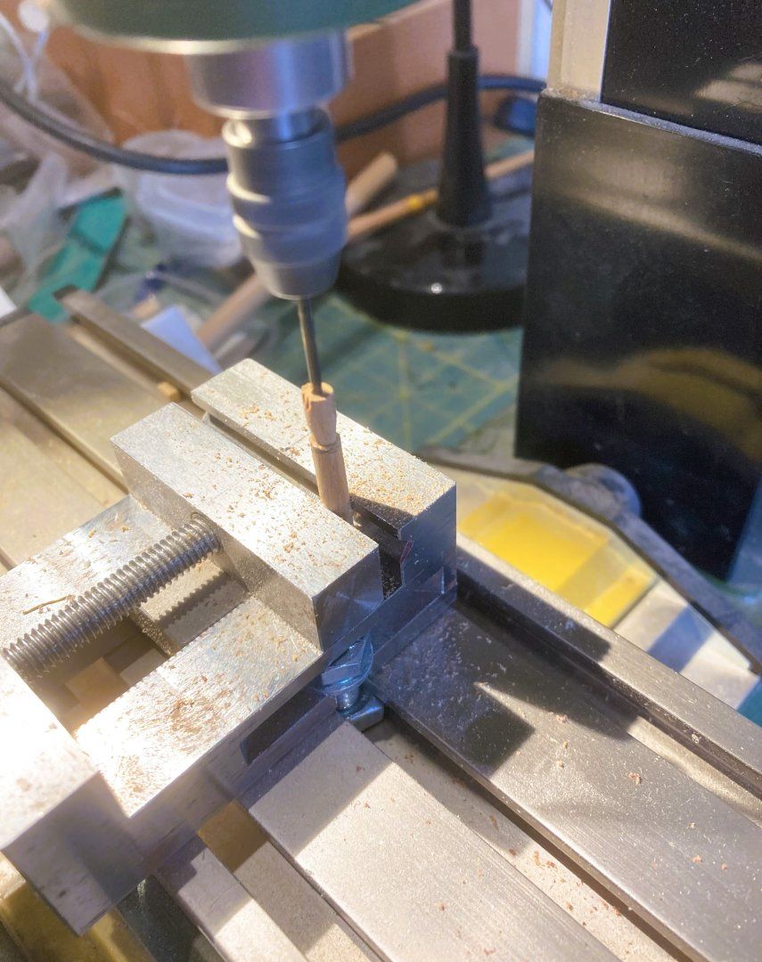
4984a
The boom was formed from 4mm square stock. The heel is of octagonal shape with sheave holes for the top ropes. There is also a crupper hole for lashing the boom to the Bowsprit.
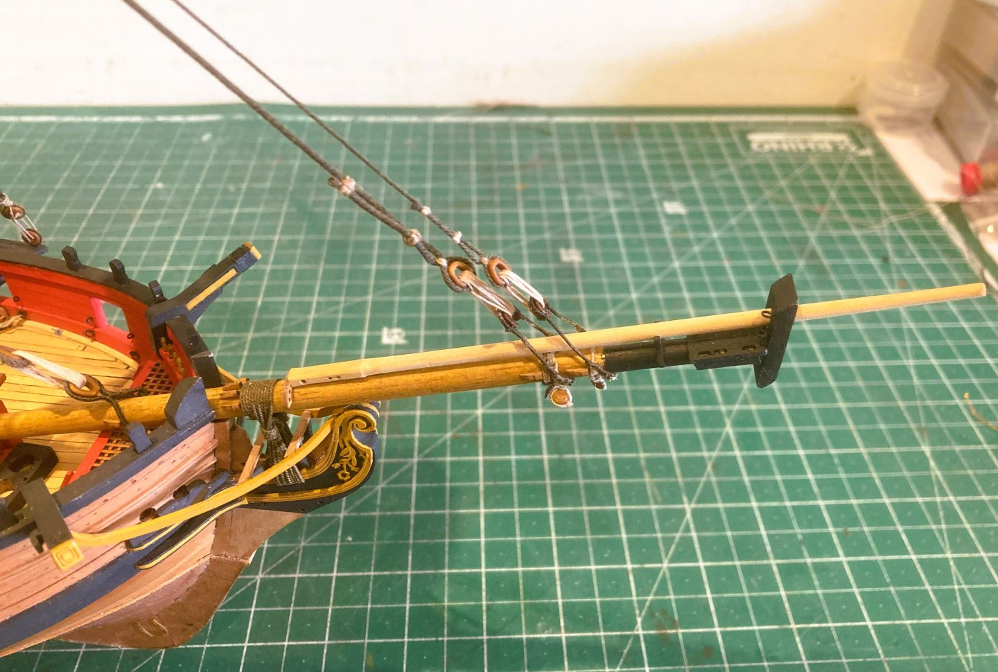
4988a

5002a
5004a

5006a
B.E.
08/07/2025
-
Post 97
The Fore stays
The stays are made up as per the Mains.
I am using Syren 1.14mm line for the Fore stay and Morope 0.80mm line for the Preventer.
The Morope has better definition than the kit kit line which otherwise is spot on for scale. (1mm and 0.75mm.)
From Steel.
Fore stay - 9½” (1.19mm)-13” Heart. (5mm) lanyard 3½”(0.4mm)
Collar – 5” (0.63mm) seizing 1”
Mouse 3x diameter of stay = 3.6mm
An open heart (Syren Resin 5mm) is used for the Fore stay collar, stropped with Syren 0.63mm line.
Quite often double strops were used but the hearts have only one groove so for Harpy it is single.
4948a
Still a tricky little exercise forming two eyes either end of a 50mm length of served line
The heart seizing is also simplified, there is only room for a couple of turns of 0.1mm line.
4963a
Fore stay collar in place.
4964a

4968a
4956a
I carved the Mouses from dowel.

4967a
Fore stay mouse fitted.
Fore Preventer stay - 6” (0.75mm) - 10” heart (4mm)
Collar – 4”(0.50mm) lanyard 2½”(0.31mm) lashings 1”
Mouse 3x diameter of stay = 2.4mm.
This is handled in the same way with slightly smaller fittings.

4982a
4981a
4980a
4979a

4975a

4974a
Onto the Bobstays….
B.E.
06/07/2025
-
Post 96
Completing the Fore shrouds.
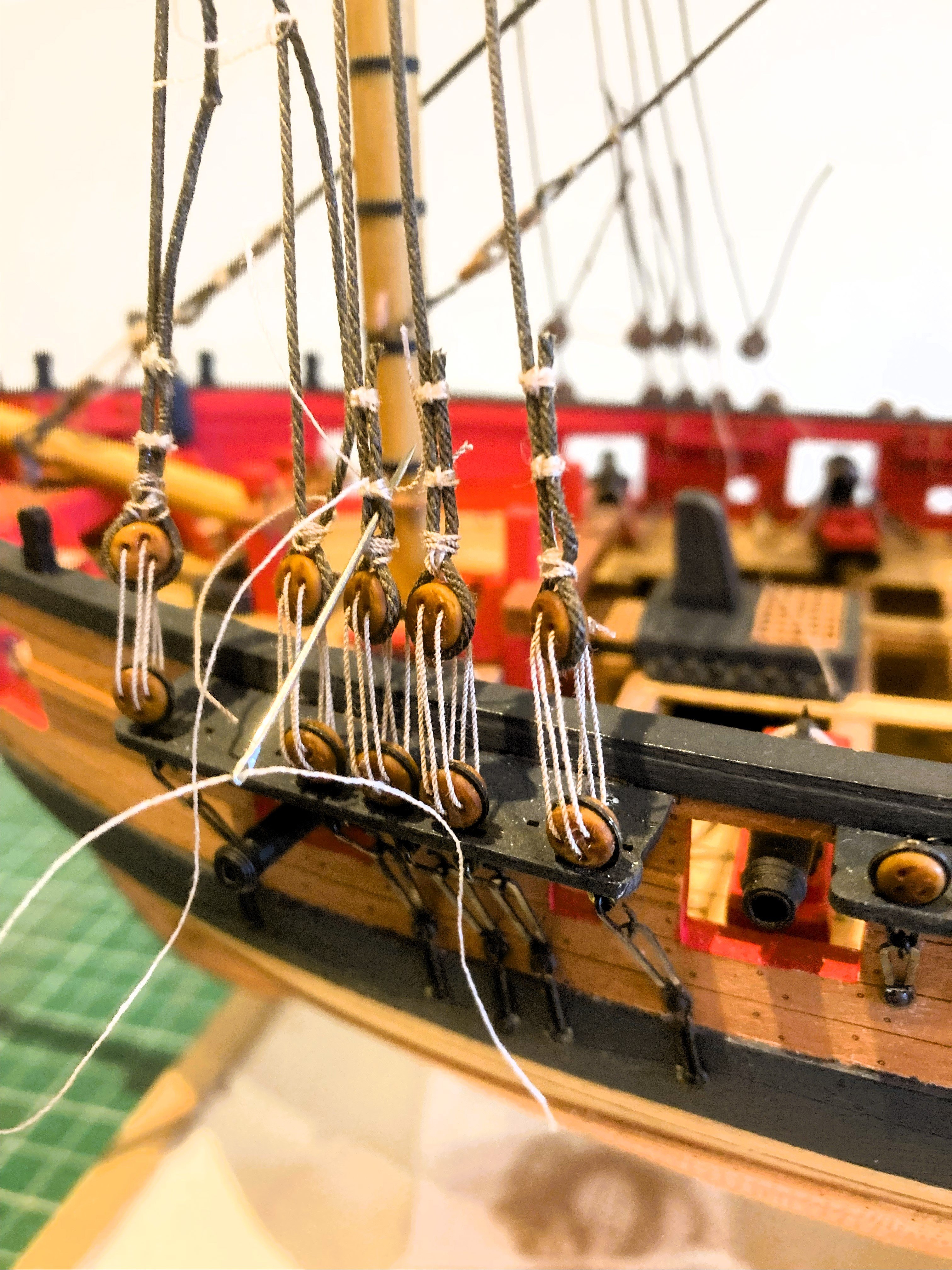
Shrouds are a very fiddly business, and applying the throat seizings is a tedious thing.

4915a
I find that using a fine needle helps with the threading of the line between the shroud and its return.

4924a

4921a

4922a
The Fore shrouds gave me more trouble than the Mains;
I seemed to spend an inordinate amount of time tweaking the shroud length before the Lanyards are eventually tied off.
This involved unpicking previously seized upper deadeyes and re-setting.
On a model a sloppy line of deadeyes is not a pretty thing.
4930a
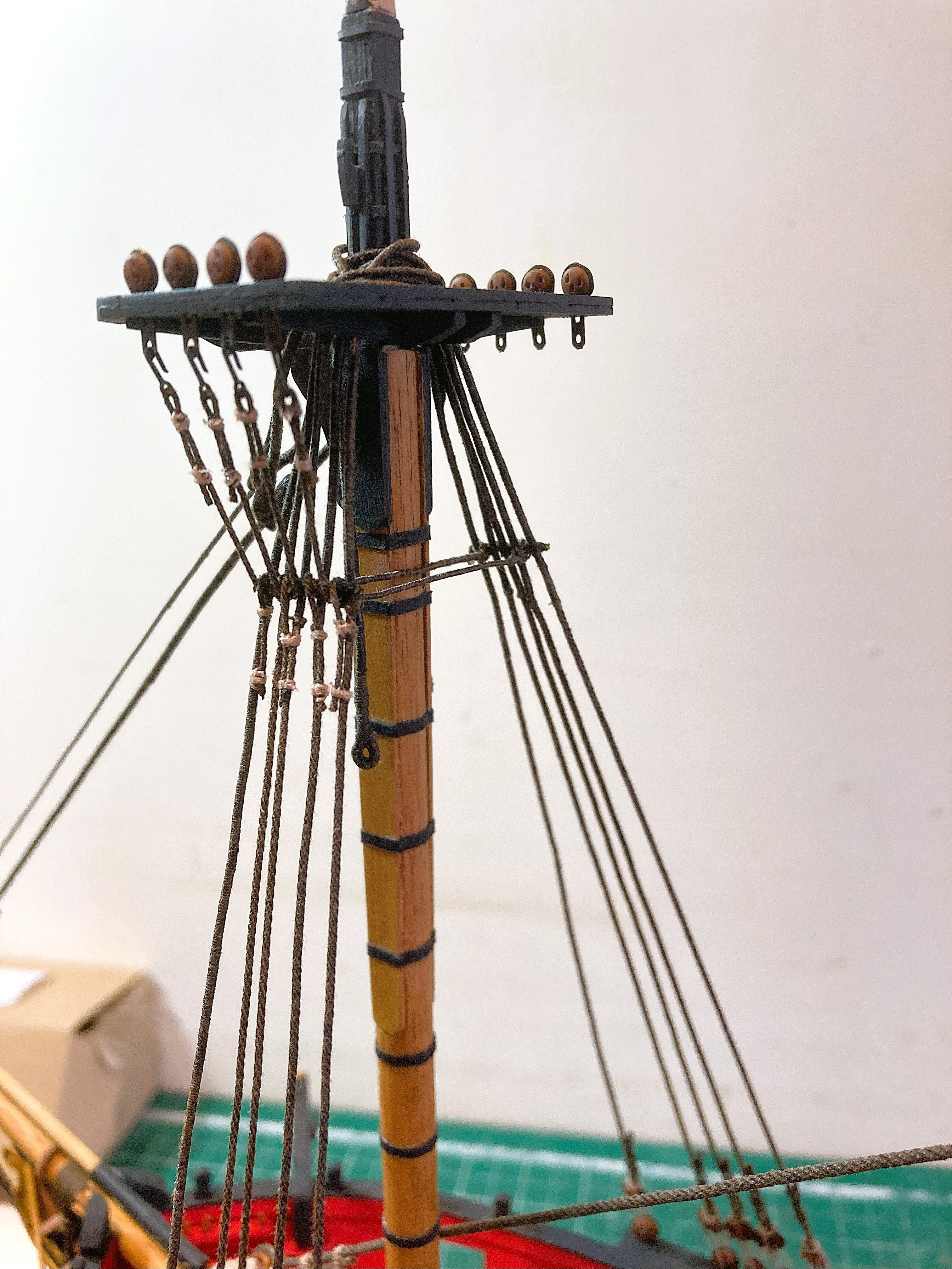
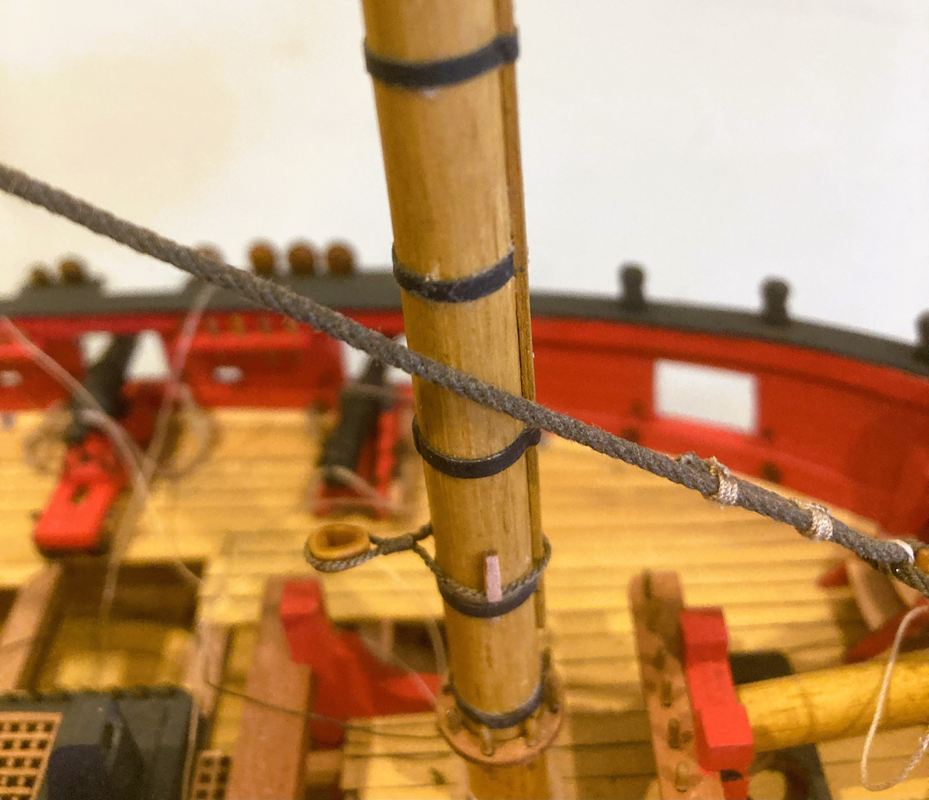
The next step is the application of the futtock staves.
According to Steel these are set as far below the trestletrees as the mast cap rises above.

4931a
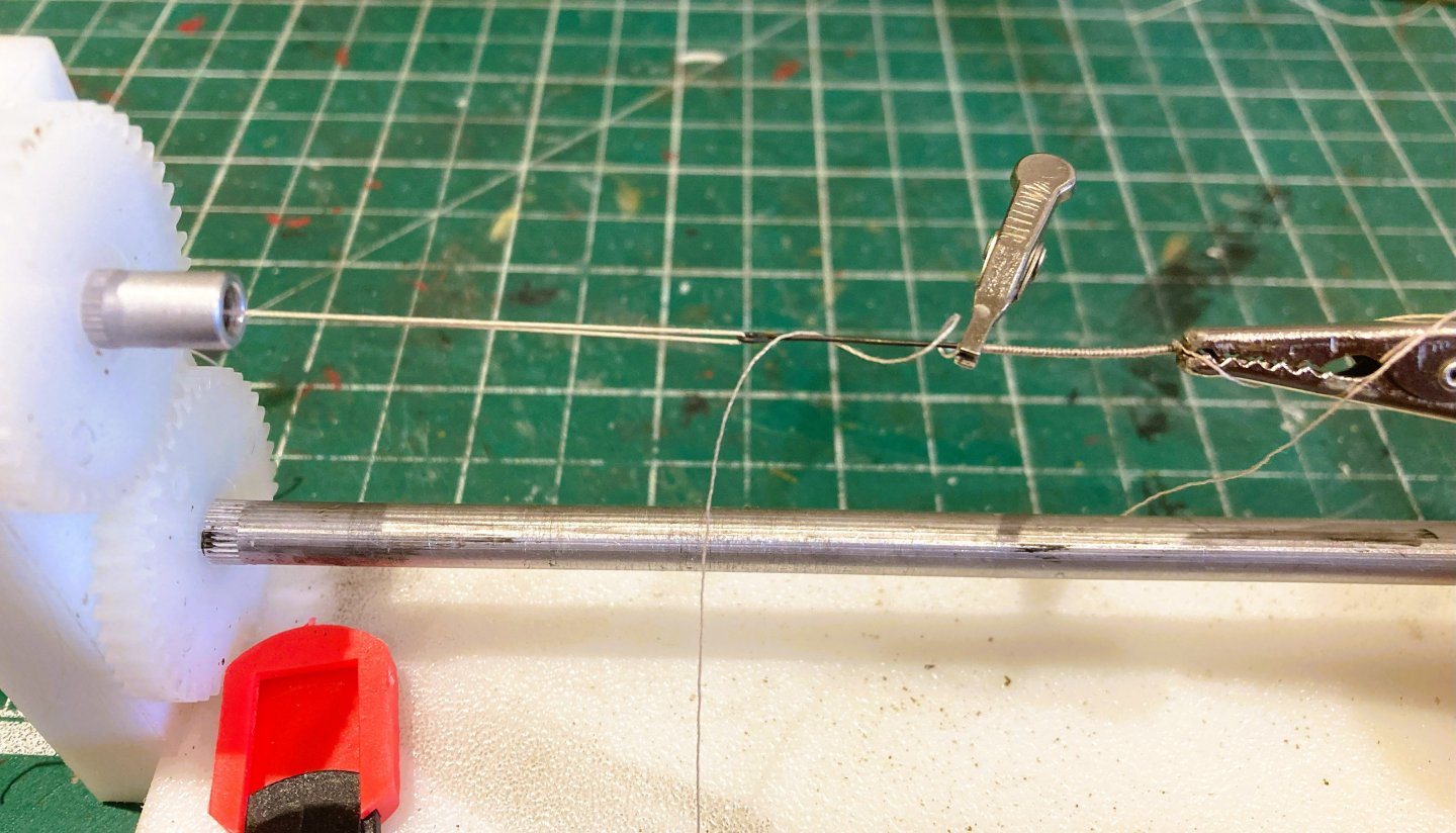
In reality the staves were of 4” circ served line, but it makes sense to use something more solid for model purposes.
I used 0.7mm ø Brass rod served with 0.1mm line.

4932a
‘Quad hands’ are a useful tool for this job, holding the bar steady whilst the outer lashings are applied.

4936a
The Futtock staves are a great device for evening out the shrouds, as well as providing the anchor point for the Futtocks and Catharpins.
The Fore stays beckon….
B.E.
02/07/2025
-
Post 95
Main stay. (Part 2)
The lower end of the stays have hearts turned in.
I am using Syren Resin versions, (6mm) for the Main Stay and (5mm) for the Preventer.
The kit provided deadeyes for this purpose are easier to fit than hearts and lanyards, but were an old fashioned option by the time of Harpy.
4901a
It is easier to fit the Preventer stay and collar with the Main stay and Fore shrouds out of the way.
I had fitted the Preventer stay at this point but found I had fed it incorrectly through the mast top.
Annoying when you have spent time doing tiny seizing and fitting of lanyards, but I couldn’t let it stand.
4895a

4897a
4898a
Lashing of the Main stay I used Syren 0.45mm line.
For the collar 0.88 mm line served with 0.1mm line was used. The tricky part of the collar is forming the eye in one short leg.
Main Preventer stay

4904a
Stropping the Preventer stay heart.
4905a
4908a
0.3mm line used for the Lanyard.
4909a
4910a
I can now attend to the Fore Shrouds.
B.E.
27/06/2025
- hollowneck, Chuck, SiriusVoyager and 20 others
-
23
-
Blue Ensign in his build log has gone into some detail about this. I will probably position the binnacle off to one side and slightly forward of the wheel.
I also left the chimney off the cabinet.
It made no sense where there is no space for a lamp.🤔
No lamp compartment, no smoke, and no requirement for a chimney.
I am looking at making two smaller single cabinets that will stand each side of the wheel.
B.E.
- dunnock, hollowneck and Richard44
-
3
-
-
Post 94
Main stay. (Part 1)
The kit plans show a simplified form of the Main/Preventer stays.
A more authentic version includes serving of the stay collars including the eye splice through which the stay passes, and a more stylish mouse to replace the kit plastic version.
The kit indicates use of deadeyes for securing the stays but I have opted for hearts which were more common during this period.
I am using Steel’s tables for an 18-14 gun ship.
Mainstay - 10” - 1.26mm - 15” Heart (6mm) Main Preventer Stay - 7” - 0.88mm - 10” Heart (4mm)
The kit line dimensions are close to this using 1.3mm line for the Main stay, and 1mm line for the Preventer stay.
For the Mainstay I am using Syren 1.37mm line, and for the Preventer 0.88mm line. The lines are stretched under weights to remove the spring before fitting.
4880a
The position of the mouse needs to be tested on the model.

4881a
4884a
Here the un-dyed Preventer stay serving is apparent, and the ‘weave’ of the mouse shows through.
4889a
I have been thinking about the positioning of the stays.
The kit arrangement has the Main stay fixed by a collar to the Foremast, and the Preventer stay running above it and beyond it to a collar on the Bowsprit.
I have some doubts about this arrangement, generally Mainstays run beyond the foremast to the bow.
Steel says that The main Preventer stay is lashed to the Foremast and the Main stay to the Bowsprit chock.
Lees comments that the Preventer stay was usually carried above the stay but that on small ships was sometimes carried under it.

4888a
Full details of my preparing and fitting of the stays and the related Mouses is fully covered in my Pegasus log, so I won’t repeat it all here.
4883a
4890a

4885a
In the case of Harpy I have decided to run the Preventer stay below the Main stay, and reverse the locations of the lashings.
Onto the lower end stay fixings.
B.E.
25/06/2025
-
Post 93
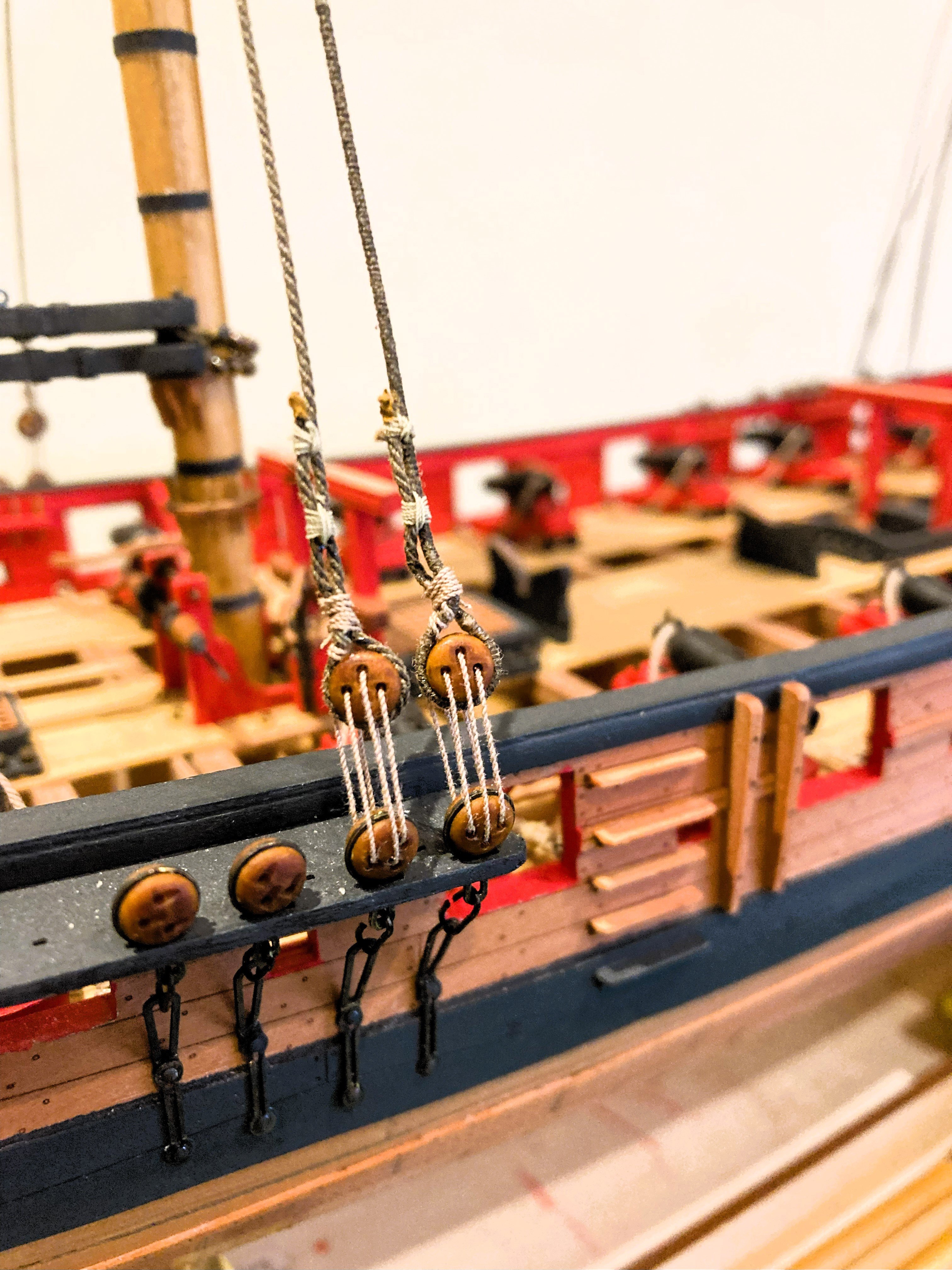
Fitting the shrouds.
It has been some five years since I last did any shroud rigging and I’m feeling a tad ring rusty, and getting the first shroud rigged took a while, including a full ‘re-do’.
4878a
Each pair of shrouds were stretched before fitting.
4828a
The first shroud is slightly more awkward due to the thicker ‘served’ line.

4847a
My approach is to set the first shroud deadeye (Starboard side) to the distance that suits my eye bearing in mind the norm of around 2-3 times the diameter of a deadeye.
The finished space between the deadeyes worked out at 7mm.

4868a
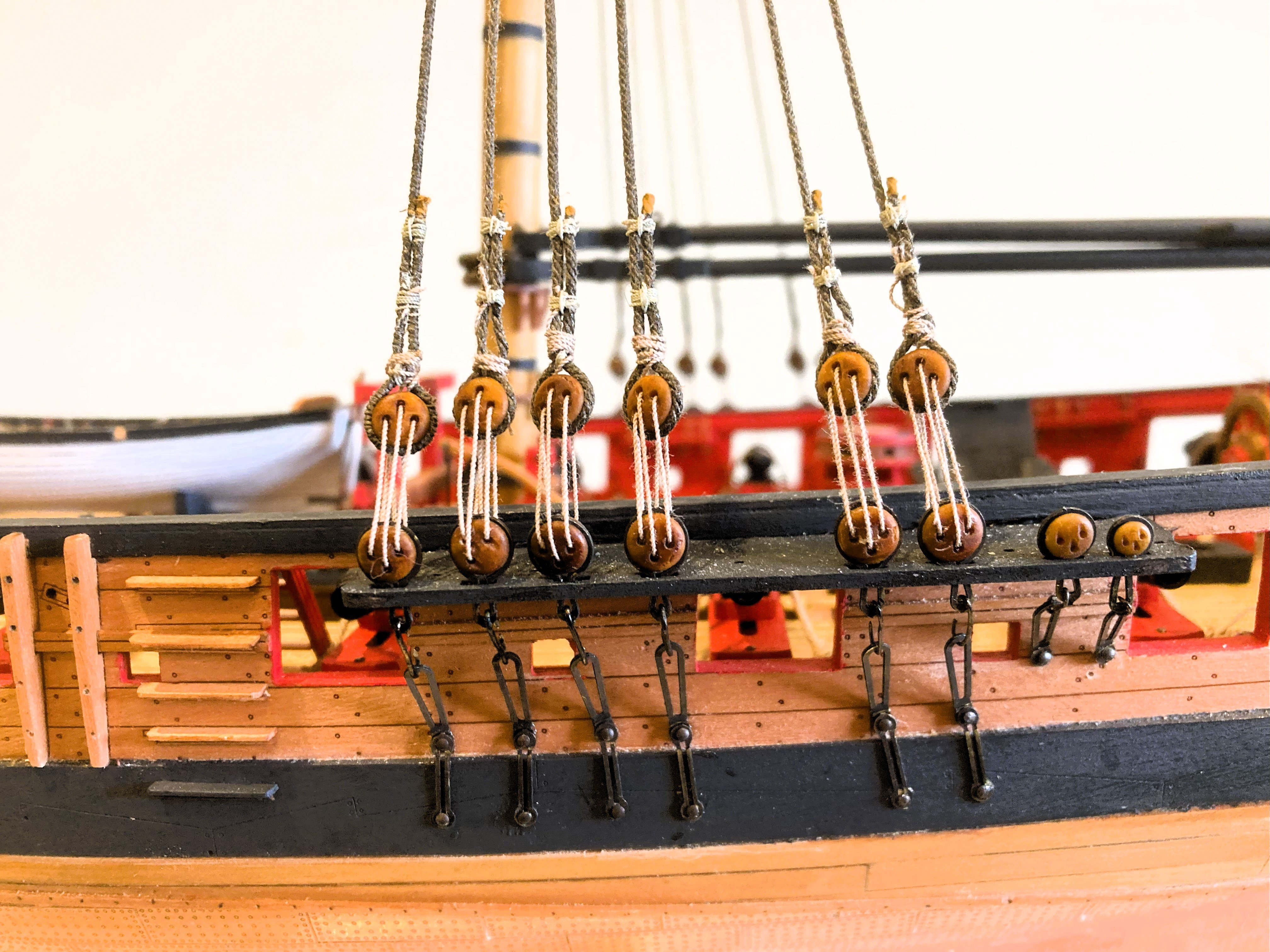
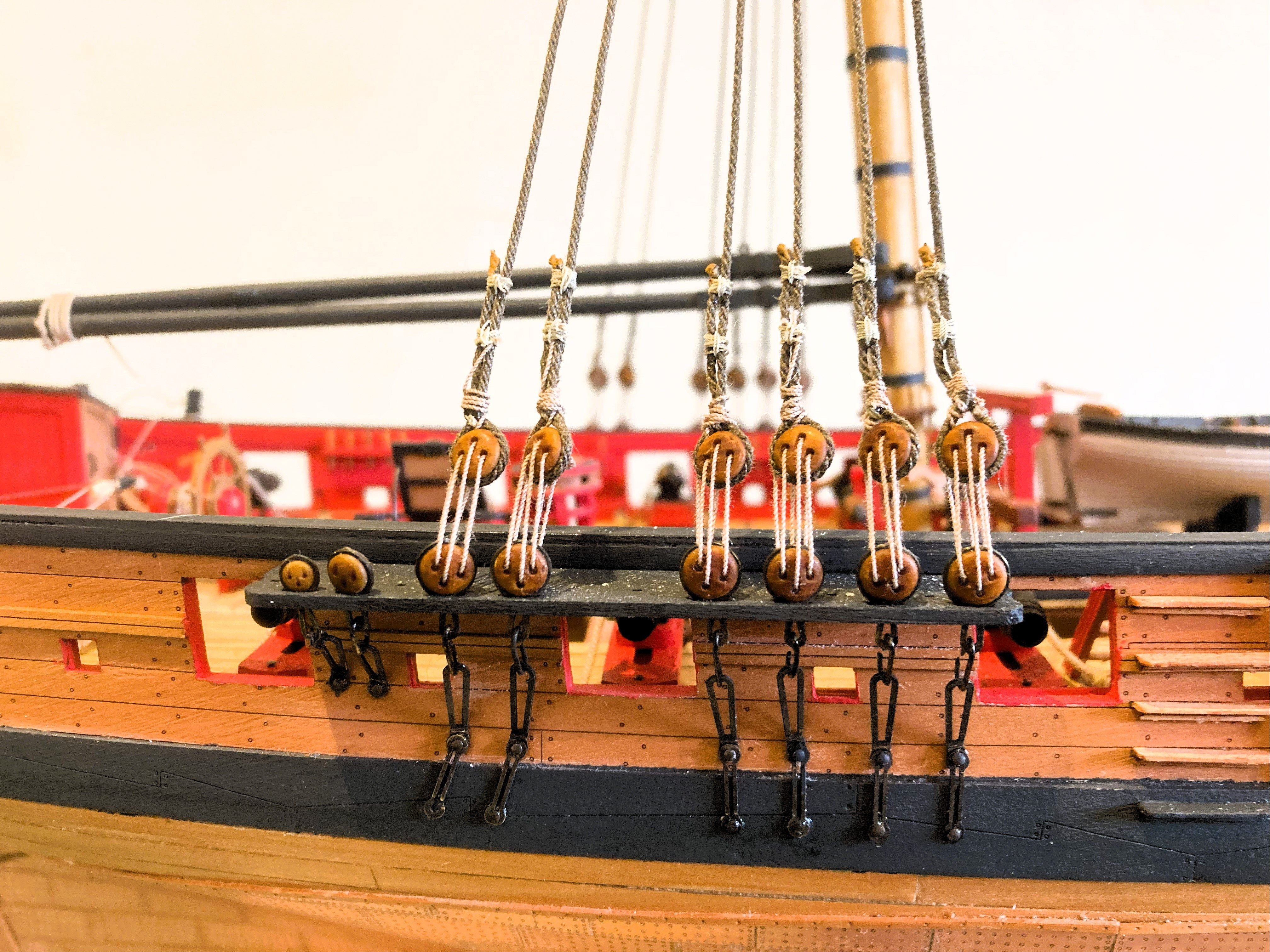
The tricky part is getting the shrouds level along the channels.

4872a
I prefer to rig the shrouds purely by eye, carefully adjusting the upper deadeye to suit the line as I move along the channel.
4869a
Not decided yet whether to dye the round seizings to match the shrouds.
4875a
4877a
The next stage is to make up the Main stays which are fitted before I attend to the Fore shrouds.
B.E.
23/06/2025
- ECK, SiriusVoyager, p.hoek and 17 others
-
20
-
Post 92
Pendents of tackles
I have re-visited these as the blocks and seizings looked too heavy to my eye, and as they are fitted before the shrouds, need to be attended to now.
I unpicked the seizings and re-used the Pendents.
This time I used a 2mm diameter thimble from Chuck’s new Resin range.
4798a
4810a
It is quite small but matches the size of 5” suggested by David Antscherl in his FFM Book (Vol IV.) The next size up 3mm, looked a tad too large to my eye.
I think this range of thimbles will prove very useful for ship modellers. 👍
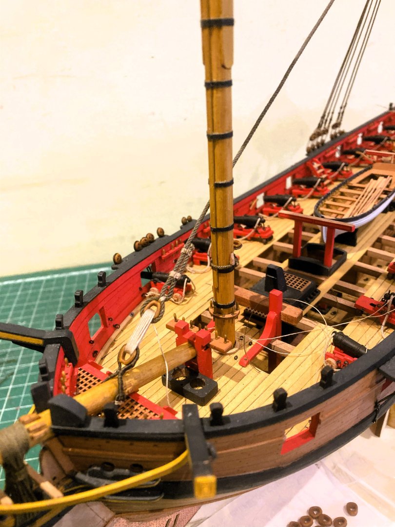
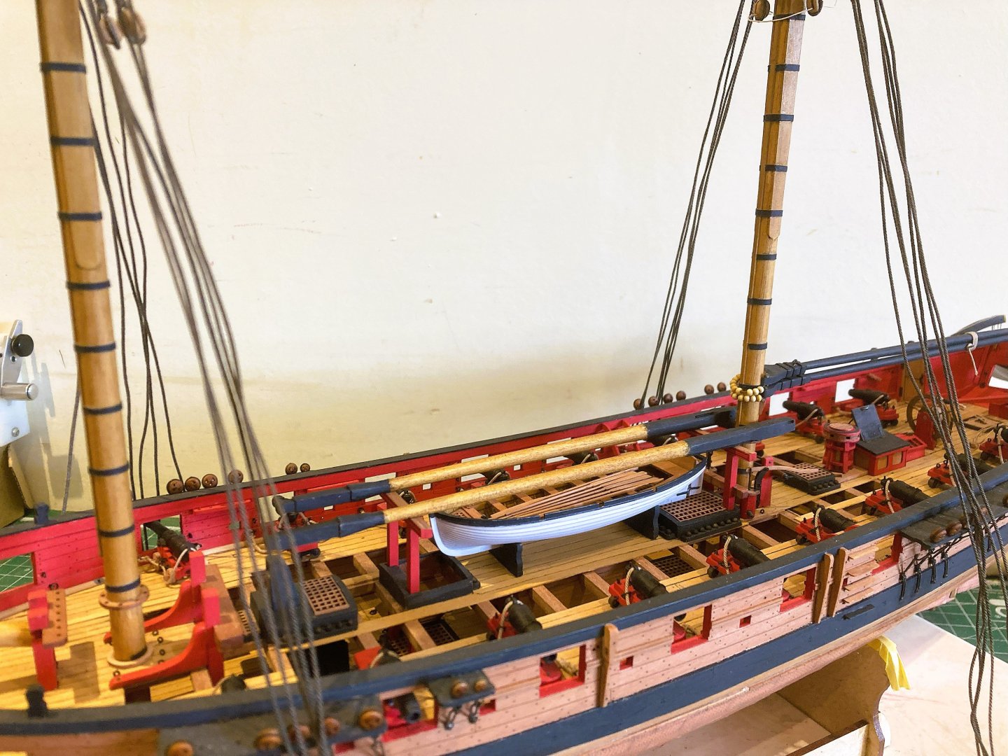
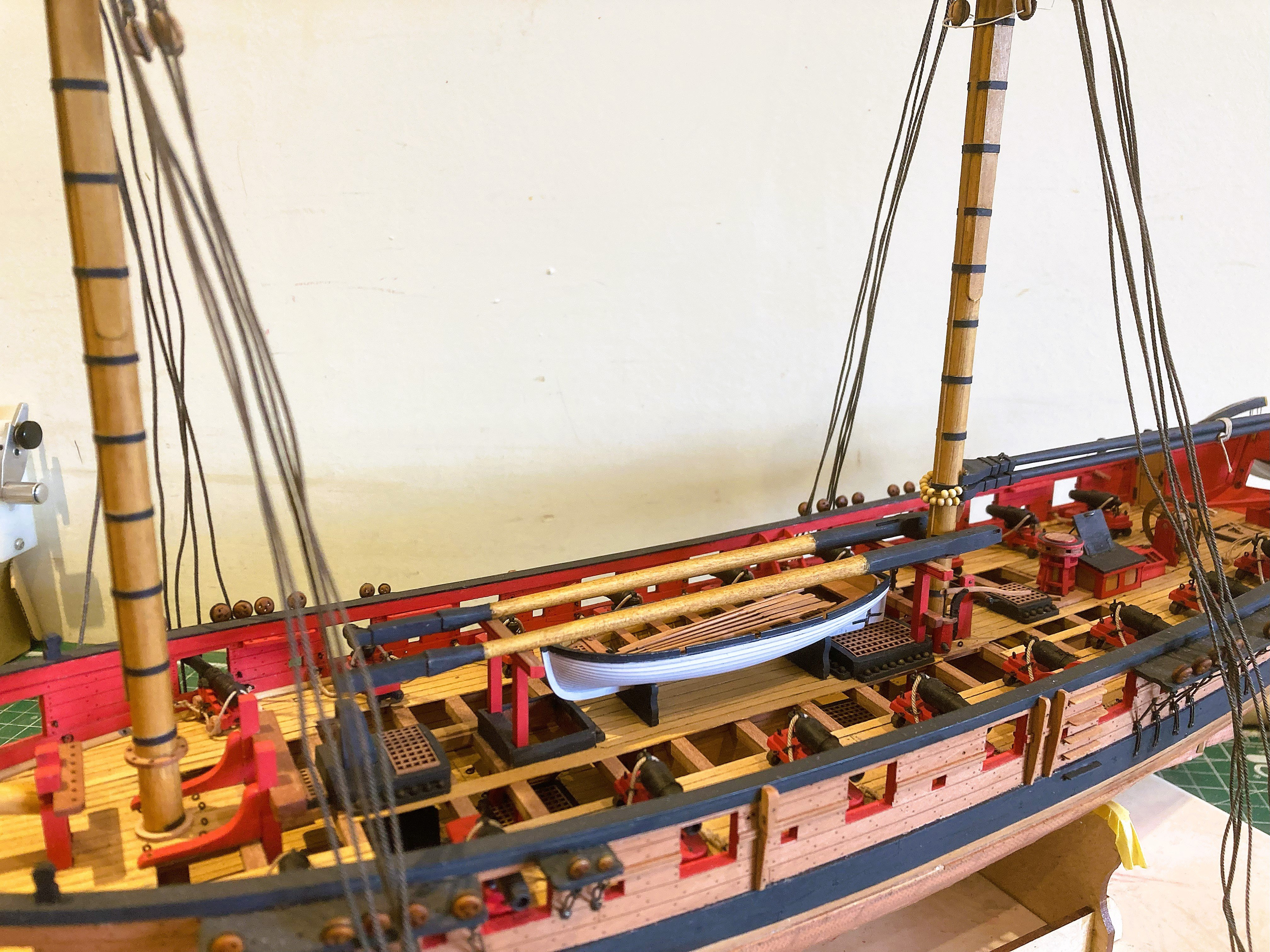
Gaff and Main Boom
This is an opportune time to attach these to the Mainmast, easier before the shrouds are rigged.
I used Boxwood parrel beads rather than the shiny black kit versions.

4854a

4855a

4848a
These were coloured using Dark oak wood stain.
4843a
No rigging for these items but seized together for convenience.
I may rig the sheet simply to hold the booms in place.
B.E.
21/06/2025
-
Cheers Guys, lowered topmasts it is.
@ Andy - I wasn't thinking of making up the yards but that is certainly an option, thank you.
B.E.
-
Thank you Glenn for your very kind comment, much appreciated.
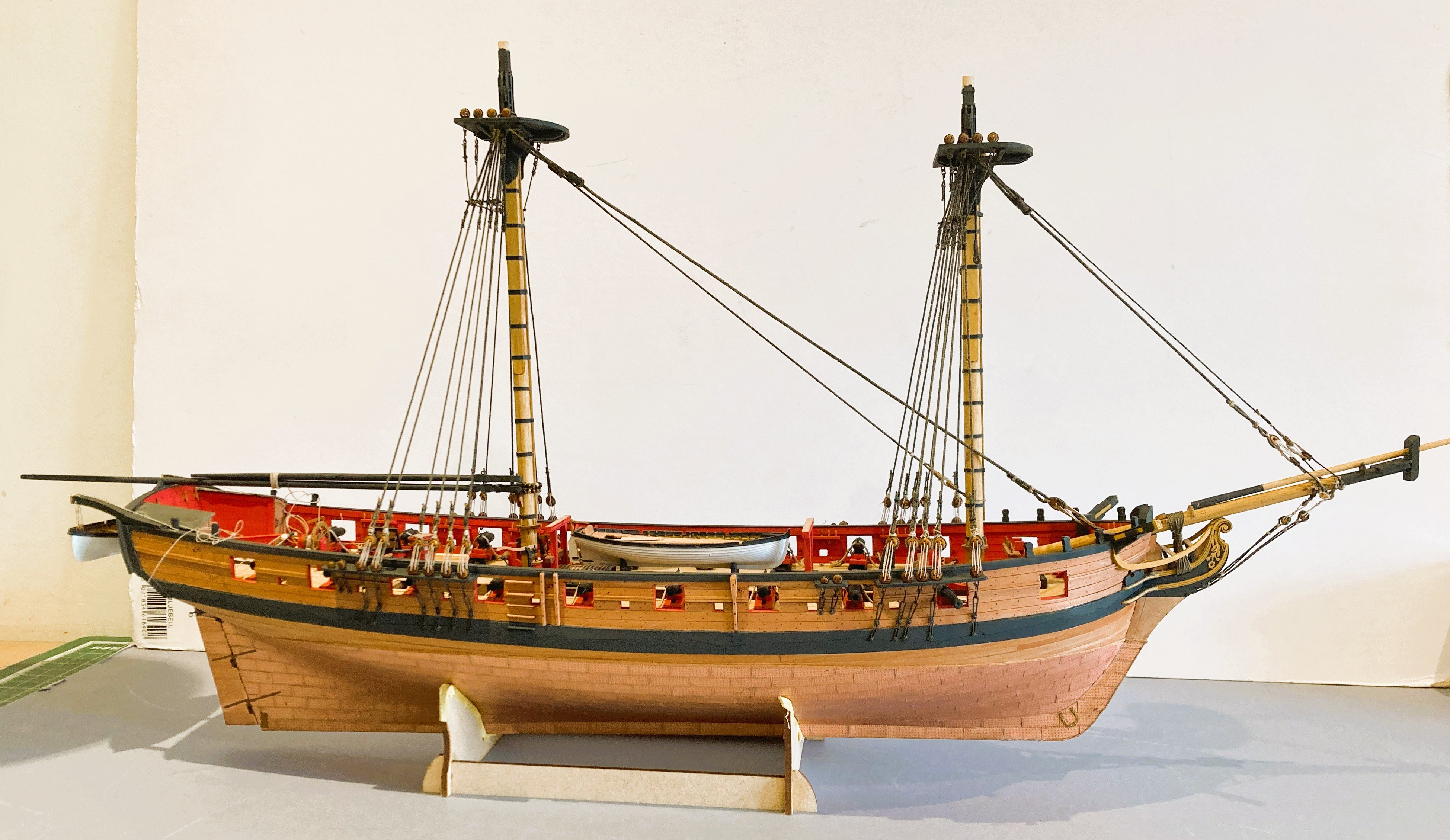
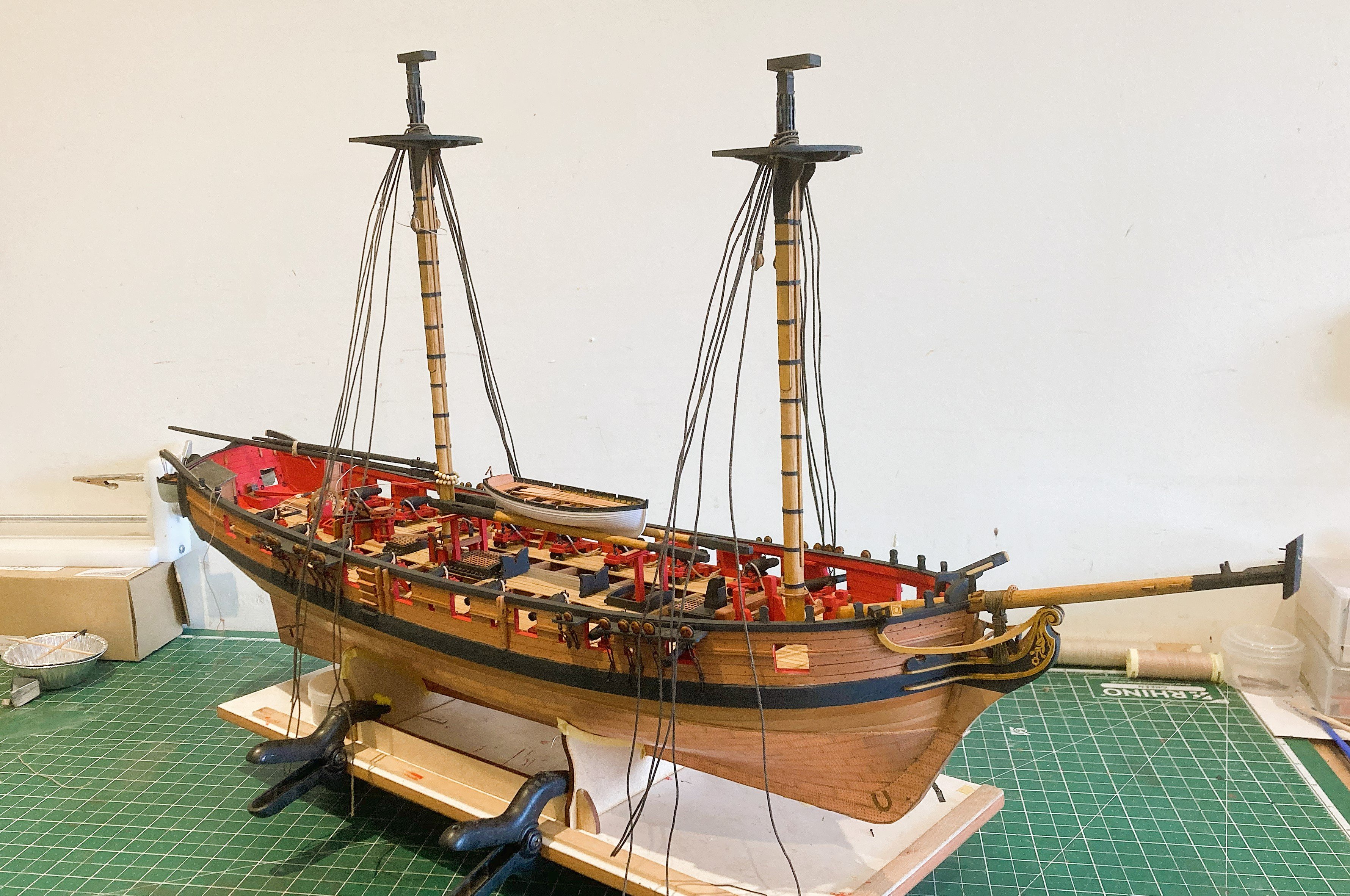
Post 91
Topmast options
I’ve yet to decide how to display the Topmasts, so I’ve been having a play around before the shrouds are fitted.
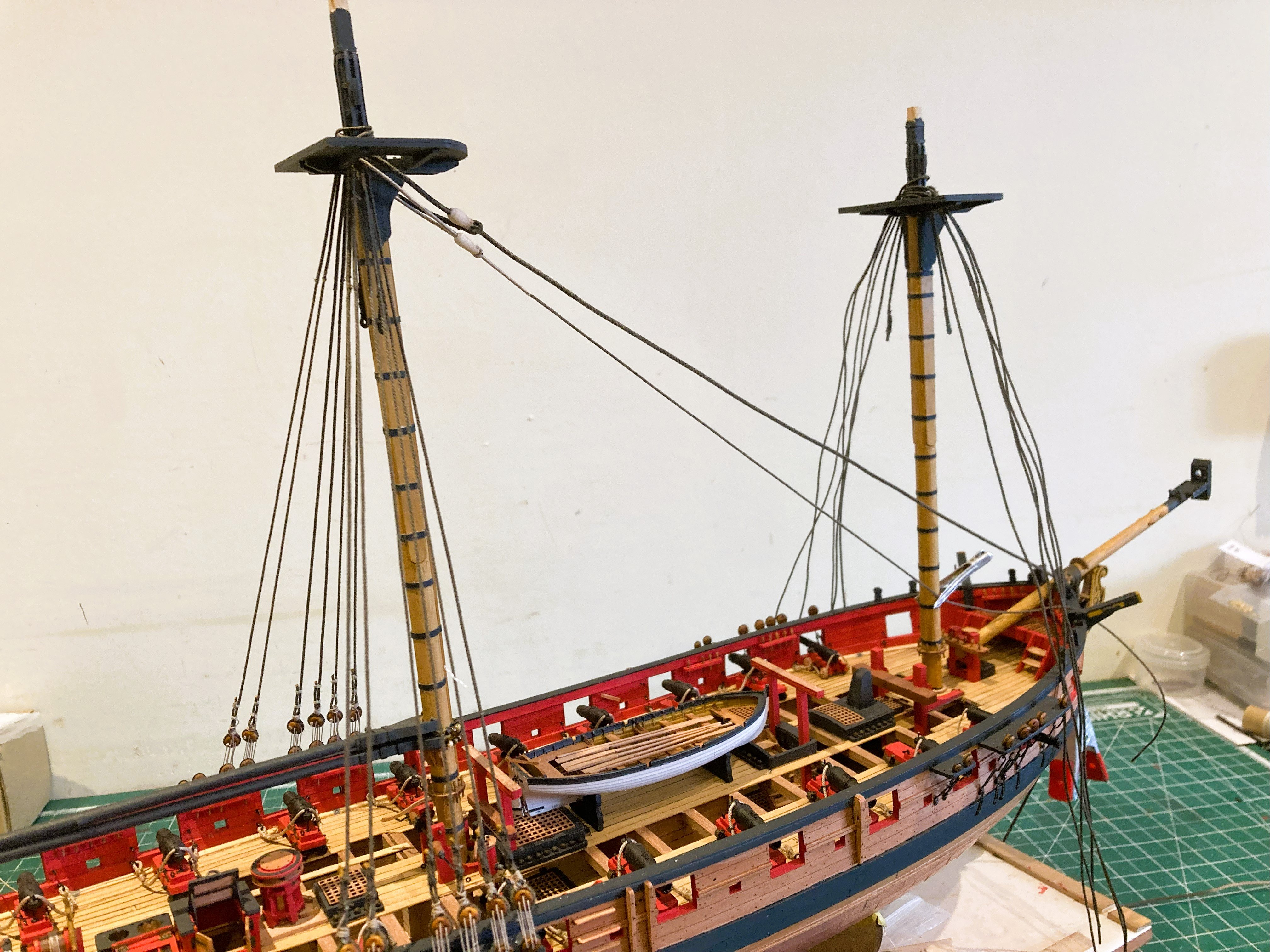
The possibilities are:
In the usual raised position.
4749a
4751a
.. but this is a non starter, I haven’t room for another tall masted model, but she would look beautiful fully rigged.
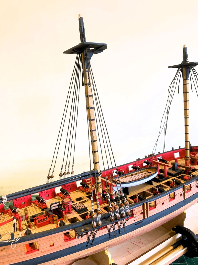
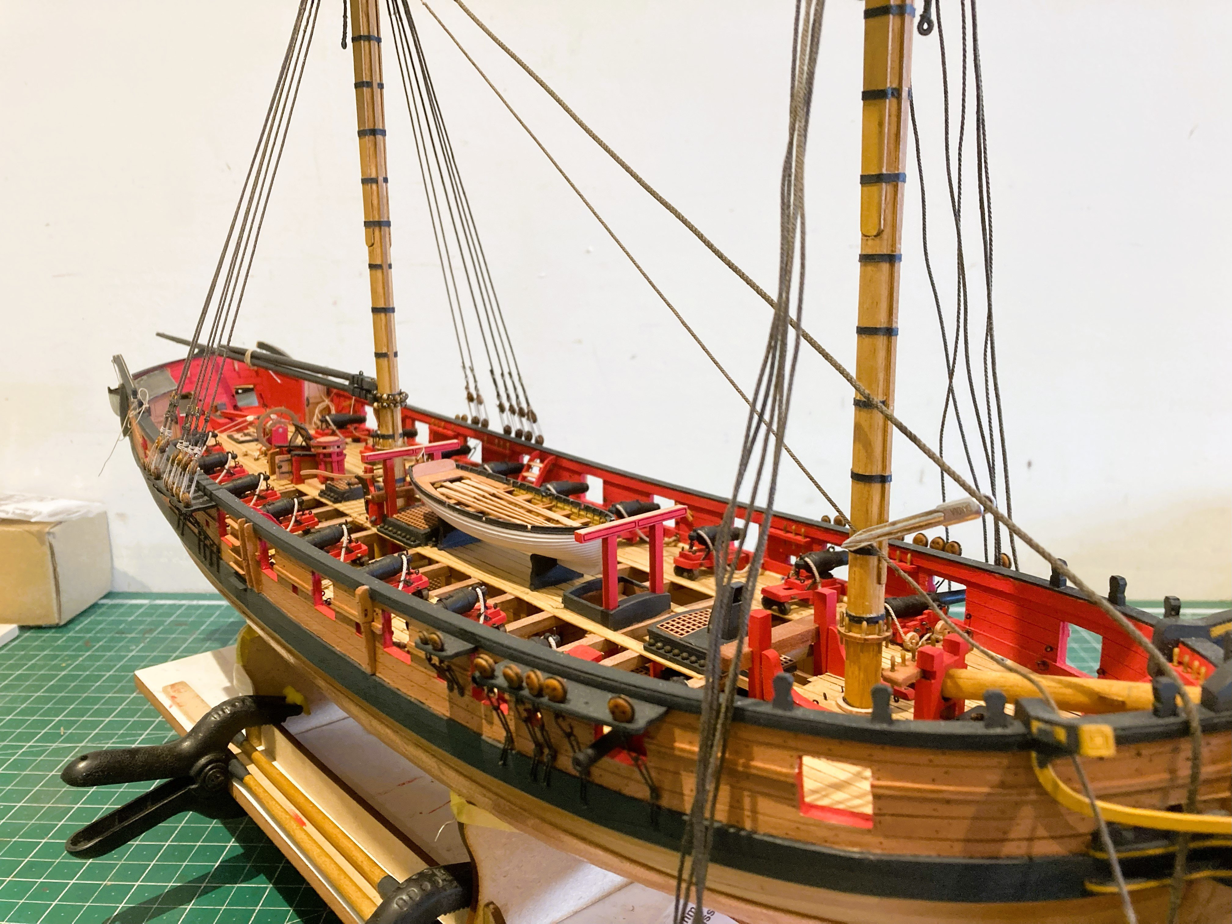
In a lowered position secured by Top ropes.

4755a

4760a

4756a
This has the advantage that it doesn’t increase the height very much. Also provides an interesting rigging arrangement.
Secured on the Gallows.
4761
4766a
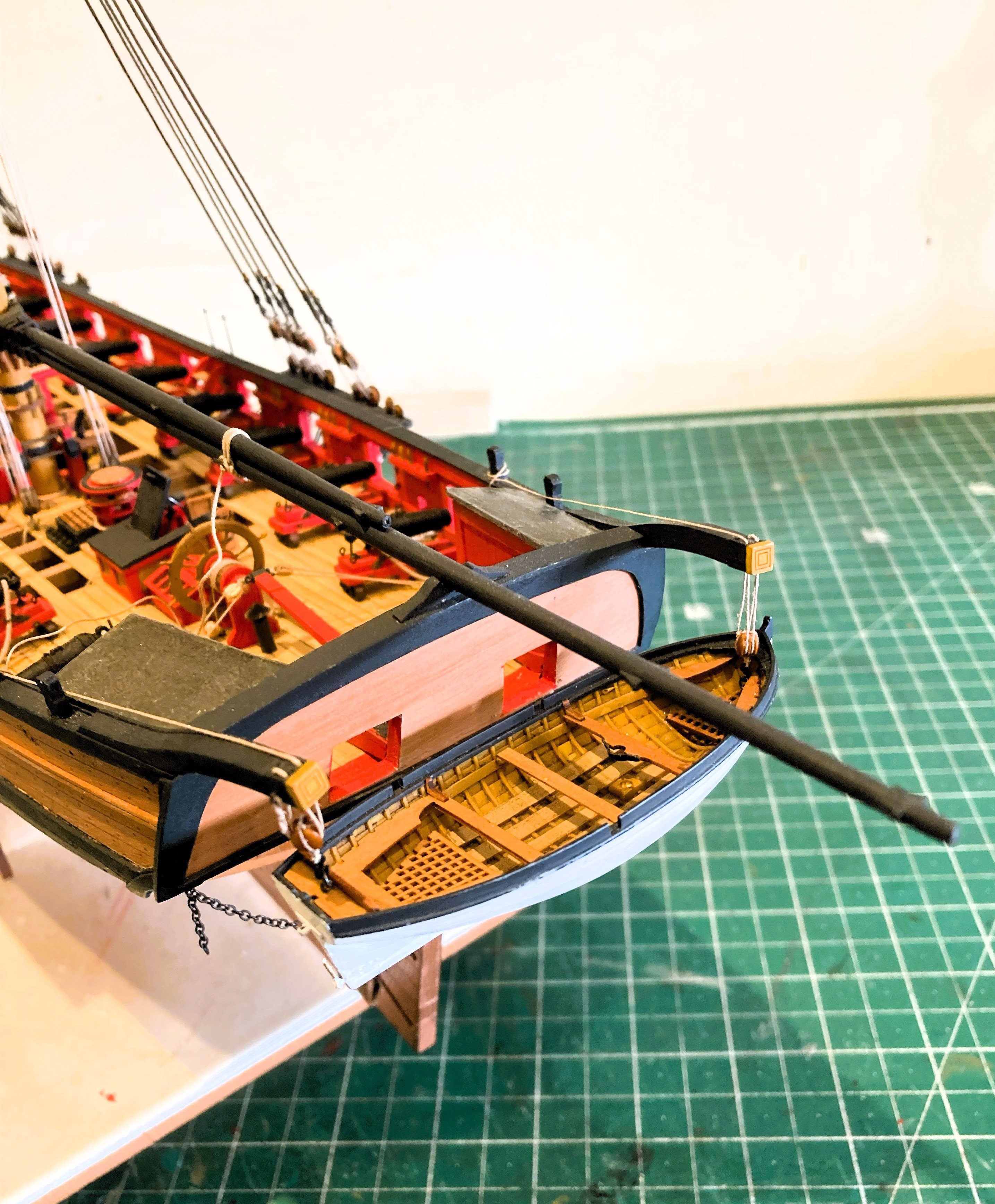
The simplest and obvious location for stowing non fitted Topmasts, but tends to obscure somewhat Chris’s beautiful little cutter, particularly if I decided to store Sweeps on the Gallows.
With the Cutter atop the masts on the Gallows

4768a

4770a
4771a
a recognised arrangement, which on a practical level clears the deck and displays the cutter to the full extent.
I don’t need to decide until the shrouds are fitted, but the lowered Topmast position is the one I’m favouring.
B.E.
19/06/2025


HMS Harpy 1796 by Blue Ensign – Vanguard Models - 1:64 scale
in - Kit build logs for subjects built from 1751 - 1800
Posted
Thank you Timmo, Chris's design talent give modellers at all skill levels the best chance of creating highly detailed and beautiful ship models.
I just love 'em.
B.E.