
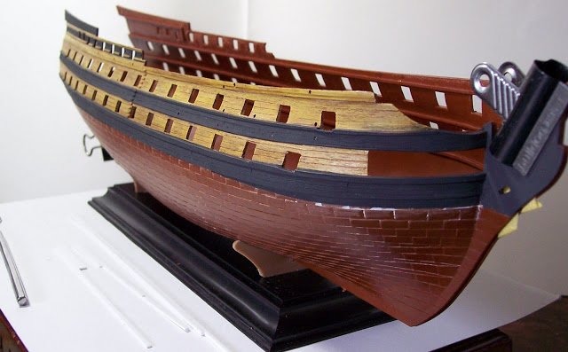
.JPG.ca33079f5815b861e67b9c2cccd37982.JPG)

Blue Ensign
-
Posts
4,286 -
Joined
-
Last visited
Content Type
Profiles
Forums
Gallery
Events
Posts posted by Blue Ensign
-
-
Thanks Dave, glad to have been of help

B.E.
-
An interesting build Revier, another one I missed previously, I look forward to more...
Regards,
B.E.
-
I've just had an enjoyable time reading through your log Ron, don't know how I missed it first time around.
I like the way you have structured your log with clear photos and a lot of 'how to' content.
A fine looking model and I will continue to follow your build with much interest.
Regards,
B.E.
-
Hi Mike, have AL supplied Limewood for the deck planking? It is normal for the hull planking particularly the first run on a double skinned hull but I've not heard of it for decking.
I get my supplies of boxwood strip from here.
http://www.originalmarquetry.co.uk/product_details_335.htm
It is good quality, but the postage is a bit pricey so I tend to order as much as I need in one go.
At 1:64 scale the 3.4mm x 0.7mm worked out almost spot on for the deck planking of Pegasus; at 1:48 scale 4.5mm x 0.7mm would be about just right.
This is the same stuff that I also did the second hull planking in and having a range of widths made life easier for spiling planks, and for those areas where a slightly wider plank was required.
B.E.
-
Doris, the beauty of what you have created is astounding, a pleasure to see.
Thank you for your videos on sculpting they have given me the impetus to attempt revised stern figures in fimo for my Pegasus.
Kind regards,
B.E.
-
Hello Ross,
Looking at the drawings in The Bounty by John Mckay in the AotS series of books, the waterline starts off right under the Main wale amidships. He states that she was coppered when taken into Naval service in 1787, but if you wish to display her uncoppered but painted she would probably have been payed with 'White stuff' over wooden sheathing, to give an off white shade of colour.
If when you have marked the waterline as indicated by David, it appears to sag towards the bow and stern when viewed from the side this is an optical illusion brought about by the rounding of the hull. To counter this just bring the line up a fraction from where it starts to round until it satisfies your eye.
Once the line is marked I use Tamiya tape to mask the area for painting, and it also gives another opportunity to check all round how the waterline looks on the model.
Good luck.
B.E.
-
Not Admiralty Plans then? how mysterious, it would be nice to know the origin.
Pickle would make a very nice desk model, I have mine in the Dining Room with full approval of the Admiralty, she really likes these small craft models. They are also fairly easy to keep clean uncased.
I rather glossed over the size differential with Pegasus, when I bought it but she likes that too certainly as a hull only model, what she will feel when she sees it masted and sparred I'm not so sure

B.E.
-
Mike,
I have used boxwood strip for my deck planking but I had no trouble with bleed when I tested the Tanganyika strips supplied with kit.
There is just a colour difference in the finish of the planking, my personal preference is for fairly pale decks.
I believe some modellers use Holly which is virtually white, but probably expensive and difficult to get in deck planking sizes unless you are going to mill your own wood.
B.E.
-
Hi George, the simple answer is that sails were not carried on the Crossjack yard, it was used only to spread the foot of the Mizen Topsail.
I believe that to carry a sail on the Crossjack would provide no sailing advantage, I did read the specifics about it some time ago but can't quite bring the detail to mind.
Cheers,
B.E.
-
Hi Peter,
That contemporary painting of Pickle by Robert Dodd does indeed show the Foremast vertical and the Mainmast with rake.
When I spoke to Richard Wright at Jotika he said that the painting was the main source of information for the placing of the gaff above the crossjack yard. They obviously didn’t also take the relative mast positions into account.
I always thought the Foremast was set a little far back but I spent hours staring at schooners in several books and came to the conclusion that the mast positions varied greatly and there were examples very similar to the Pickle kit set up.
Colin White the Curator of the Naval Museum has stated As far as we have been able to tell, no plans of Pickle survive and none of the many paintings she appears in can be considered definitive.
The Naval museum model of the Pickle commissioned in 1968 is also at variance with what we know of Pickle in terms of the armament and doubts have been raised that the model truly represented her. There is a suggestion that it was based on the plans of HMS Haddock.
http://collections.rmg.co.uk/collections/objects/85908.html
Colin White is also said to believe that the model was not intended to be “Pickle“, rather a close representation of a naval schooner of that period.
This is partly because of the inconclusive research available when the model was made and partly because the model is very unlike any smart cutter, as “Sting” was described, of the period.
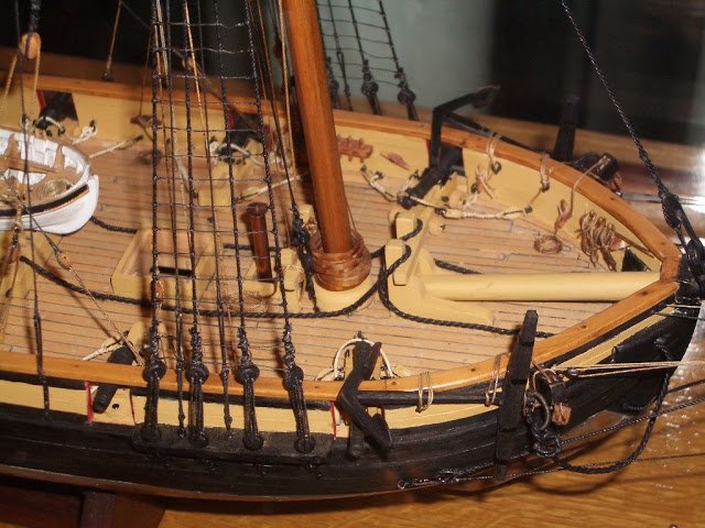
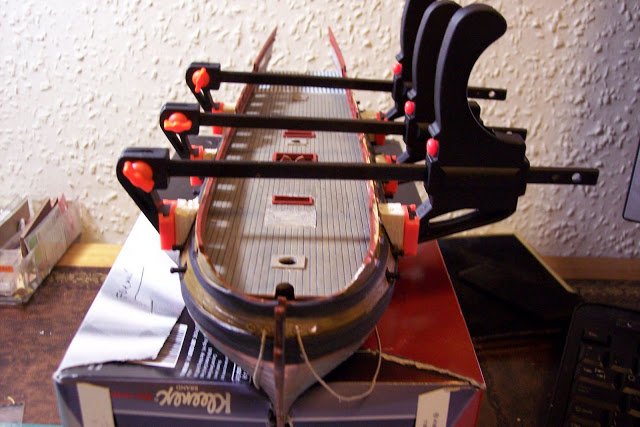
Significantly, by the late 18th century “smart cutters” were built with finer lines than those of the model.For those who may not have seen the Naval Museum model here's a few photos taken for me by my friend Chris (chrism as on the old MSW) as part of my research for the build.
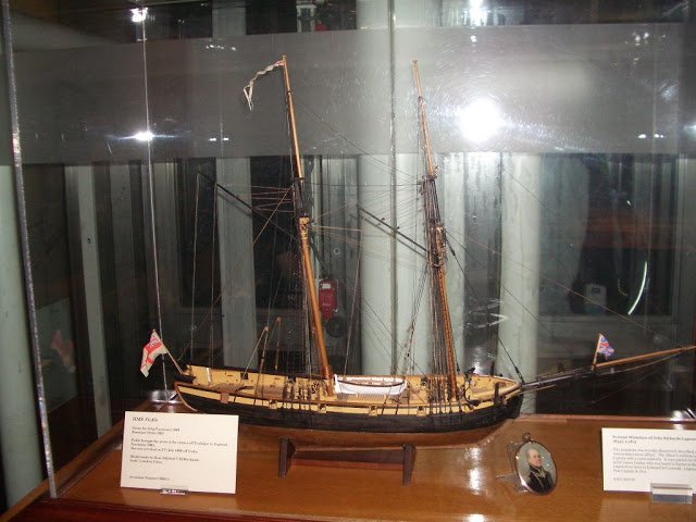
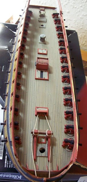
The set up with the bitts is different to the kit, and there is no windlass.
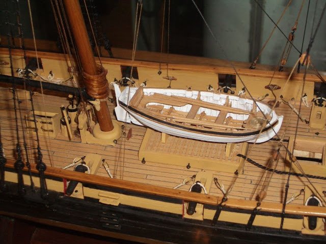
There is just one small jolly boat set centrally, the set up not particularly well done I thought.
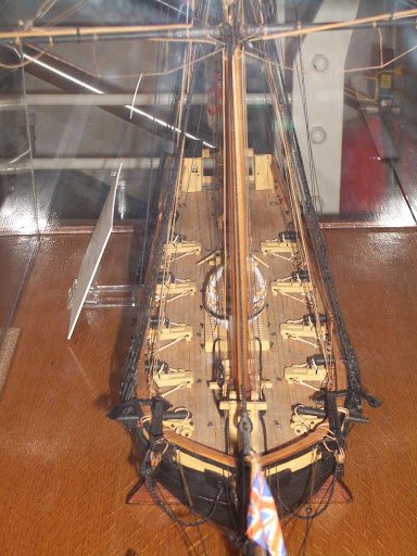
She is fitted with eight carronades and two carriage guns, not what is recorded as the Pickle ordnance.
As with many things to do with our interest there are more questions than answers, and even the ‘experts’ can’t always agree.
All of this is of course academic as what we are dealing with here is a beginner level kit that most builders accept at face value and it does make up into an attractive model with more than a nod to a schooner of the period.
Jotika may be at fault by claiming that the kit is an exact scale model designed using original Admiralty plans , which infers that the plans were of Pickle without clarifying that they didn’t specifically mean Pickle, but plans of a schooner of the period. There are a lot worse examples in other kit manufacturers claiming a real history for none existent ships.
I have seen working boats of the sort of Pickle dimension with the small jolly boat parked on the side, but I also think centrally placed would be better. Pickle was said to carry a cutter and a jolly boat.
On the model there is just enough room to fit a scale 16’ cutter (Jolly boat) between the Mainmast and the Galley chimney, and I could have placed the smaller boat in that position.
I still like Pickle as a model and the foregoing would not put me off building it.
Regards,
B.E.
- jaerschen, dafi, GrandpaPhil and 1 other
-
 4
4
-
She looks magnificent Augie, a great advertisement for the kit, you must be feeling well satisfied I know I would be.
Cheers,
B.E.
-
Hi Peter thanks for looking in on my build, it alerted me to your own fine Pegasus. It really is a great kit allowing for all degrees of enchancements and I like what you are doing with yours.
Regards,
B.E.
-
B.E. .......... this build is just outstanding !!! Thanks for posting . It's such a pleasure to look at your work .
Frank
B.E. .......... this build is just outstanding !!! Thanks for posting . It's such a pleasure to look at your work .
Frank
Cheers Frank
Thank you for the advice!
My ship just came in today. I did a little dryfit of the hull and it seems that the fit a bit off in the middle. Did you have the same sort of issue with your model?
regards,
Lukas
Hi Lukas,
I've just had a look at the two hull halves of the spare hull I have and they seem to fit together ok.
I commented on the build that the hull goes together without any trouble at all, but that the gun-deck is a tight fit requiring spreading of the upper bulwarks.
The Upper deck was a different matter, here's what I said at the time.
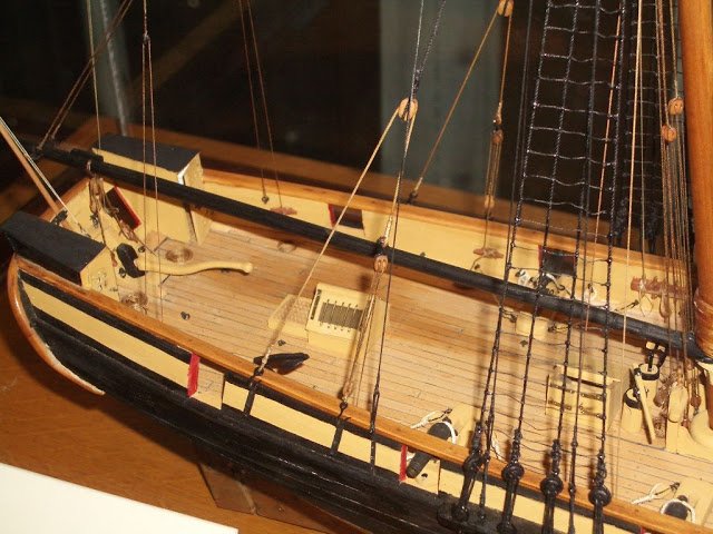
The Upper deck
This was the very devil to fit, due to the quite severe tumblehome and the pressure needed to force the deck into place without dislodging any of the fittings on the gun-deck or the cannon protruding thro’ the hull.
At one point it seemed almost that I would split the upper bulwarks trying to get the deck below the Quarterdeck level. I fitted the deck dry, and once in place I don’t think I would have got it out again without damage.
As with the Gun-deck I was able to depress the deck below the support ridges along the inside of the hull and let the deck spring back into place, once glue had been applied to the ledges.
Things didn’t really go smoothly, quite a bit of pressure is needed to secure the deck edges to the hull, and even so the bond broke in one or two places, fortunately not where it will be ultimately seen.
In the process three cannon were dislodged on the Gun-deck, fortunately the breeching ropes held them to allow re-fixing with a little super-glue inserted thro’ the port.
Tip
For the purposes of applying pressure to the awkward hull shape to secure the decks I used those small and cheap single handed clamps. If small blocks of balsa are super-glued to the face of the jaws they can be cut to shape, a wedge in this case, so that the clamp holds square to the job, and applies pressure without slipping or damaging the paint surface.
I was relieved when that bit of the assembly was completed.
B.E.
- JerryTodd and FrankWouts
-
2
-
She's quite a beast Mike, and it looks like you are making a good start. Do you have the book The Frigate Surprise by Brian Lavery and Geoff Hunt, it does contain some supportive information to assist a build, particularly drawings by Marquardt.
One area amongst many that let the kit down are the headworks, these will need virtually a scratch build to get them looking anything like.
Re the caulking; I use the one edge only method using a Pilot chisel point broad marker, I have never had any problems with bleed.
I do however mark the butt ends using a pencil because of the end grain.
Look forward to seeing your progress.
B.E.
-
Thanks guys for your support of my build.
Lukas, the model is all handpainted, I think it gives a more appropriate finish to period ships.
Regards,
B.E.
-
Hi Jason, that's how I did it on Pegasus, except I didn't mark in the scarph joint, nicely done
B.E.
-
I like the innovations you have made to your build Robert, very nice work.
Well done.
B.E.
-
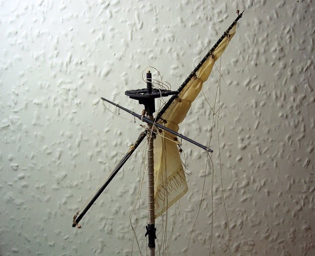
A simple man’s guide to sail making (part two)
The sail has been cut out complete with a hem all the way round, the positions of the cringles have been marked along the edges.
The hems are folded over and a small slit where the cringles are to be placed is made with the scalpel.
0.1mm line is then placed along the hem inside the fold and fished thro with a small pointy thing, to form the cringles.
This is the position so reached.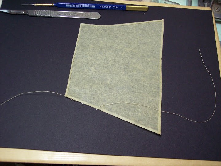
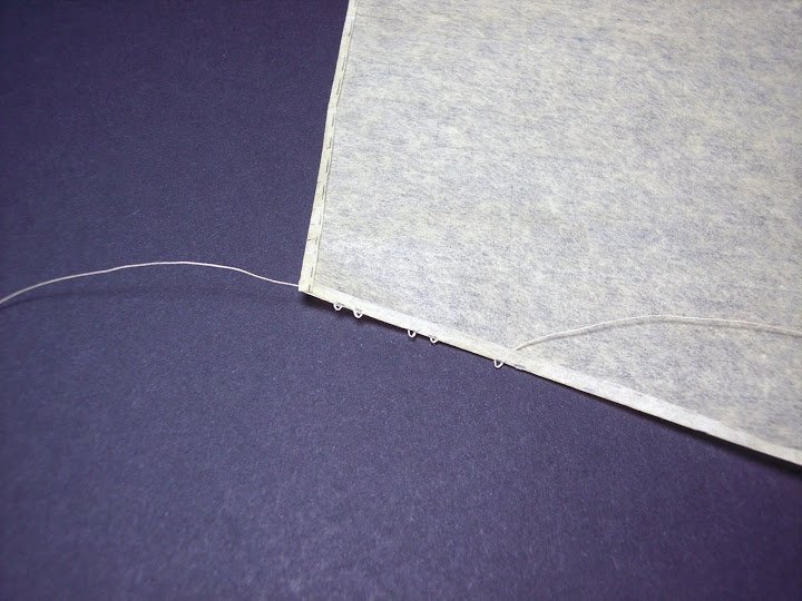
After the first few cringles have been formed the hem is glued down using neat PVA to hold the cringles in place.
In the pic below all the cringles have now been put into place.
Down each side from the top are the three pairs of Reef cringles, followed by three Bowline cringles; the leech line is attached thro’ the top two.
At the clue is the cringle for the blocks..
Across the foot of the sail are the cringles for the buntlines.
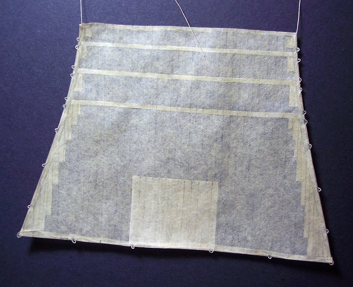
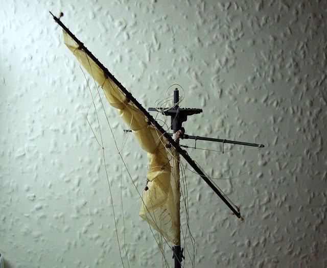
Bands, patches and linings
Additional strengthening pieces of ‘cloth’ are now required to be added to the sail. These are all attached to the aft side of the sail as shown above (Fore side on British ships.)
They comprise:
The reef bands, three narrow strips thro’ which the reef points are fixed.
The Patches small squares of material below the reef cringles at the leech.
The Top lining, the most distinctive addition whose purpose is to protect the sail from wear by friction against the mast top.
The Lining cloths which are strengthening strips staggered down the leech of the sail.A bit like wallpapering this part, cut it to size, slap on the paste, and stick it down.
With the light behind the full effect of the various additions can now be seen.
A series of holes were drilled thro’ the Reef bands to take the Reef points, and again on the Head lining to take the Robands.
Some 150 reef points are required on the Topsail.
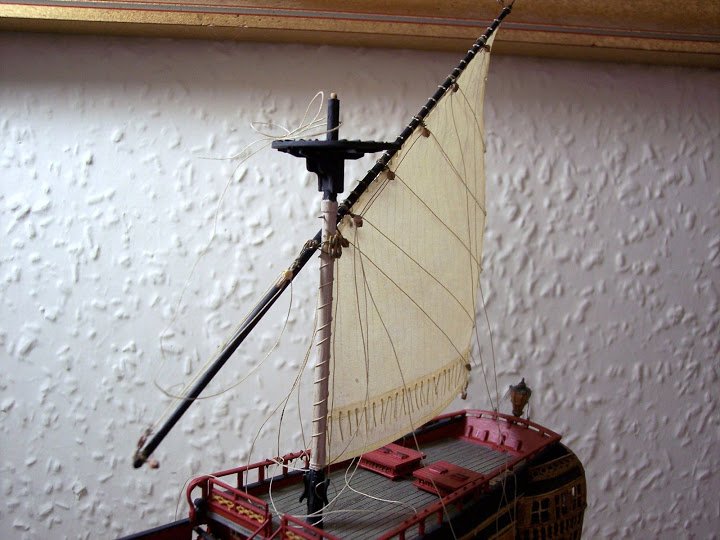
Once the sails are in place they can be manipulated at any later stage by the simple expediency of wetting them down.
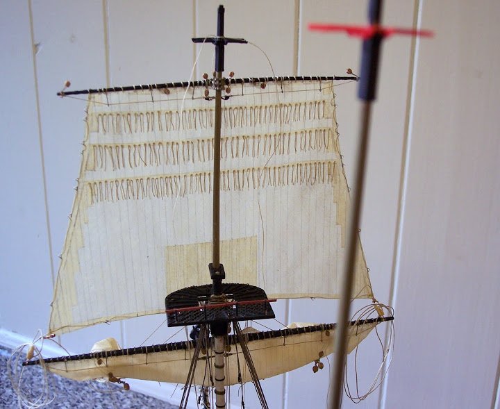
The Mizen sail, the Brails that control the sail furling are all in place, there are matching lines on each side of the sail.
a simple wet down of the sail and haul on the Brails and the sail is loosely furled.
Modelspan is a tough material and in my workings with I had no failures.
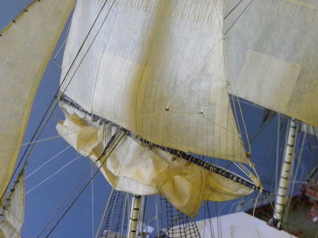
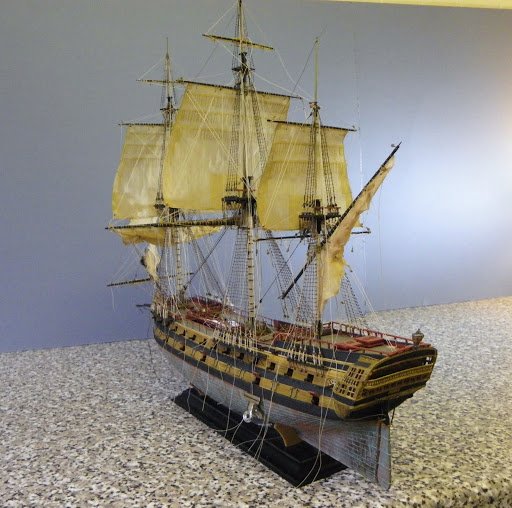
I would use modelspan for kitting out models certainly up to 1:96 scale.
Cheers,
B.E.
-
Just for you JP I'll dig out my posts on the subject.
A Simple man’s guide to small scale sail making.
For this I used modelspan tissue at 21gsm.
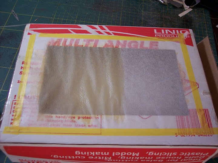
This is where it all starts, my patent jig for sail making.
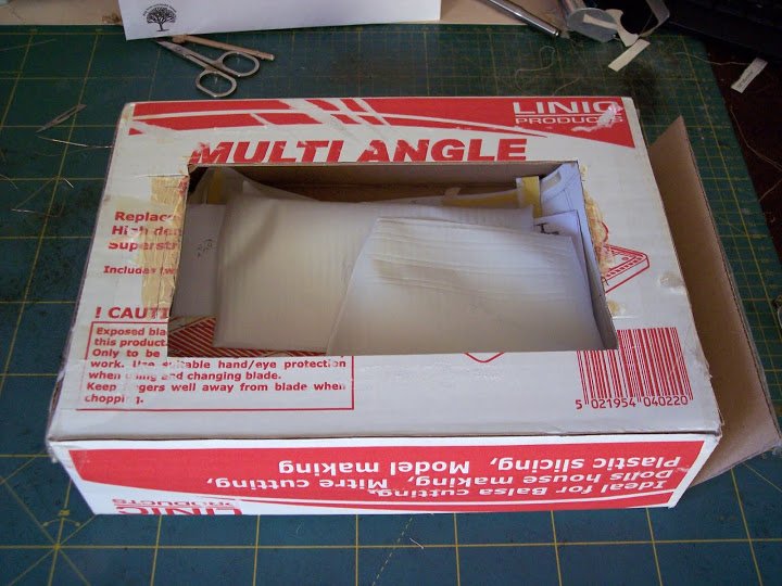
Well alright it’s a box with a hole cut into it.
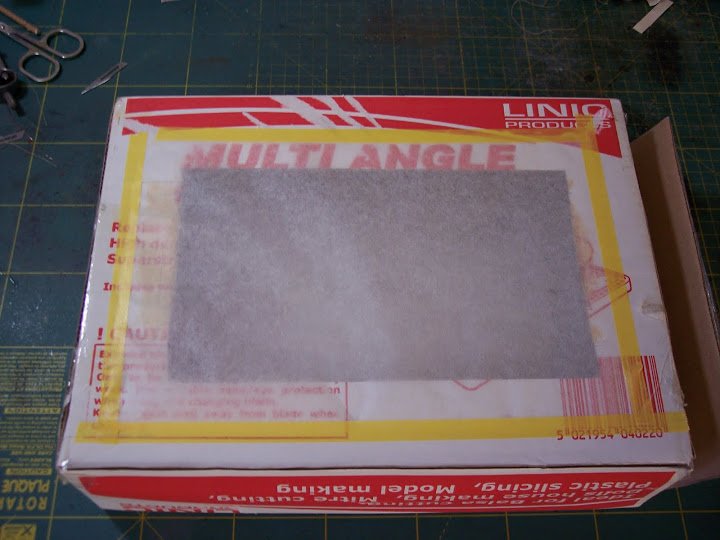
The Modelspan tissue is taped over the hole – make sure the hole is large enough for the sail dimensions.
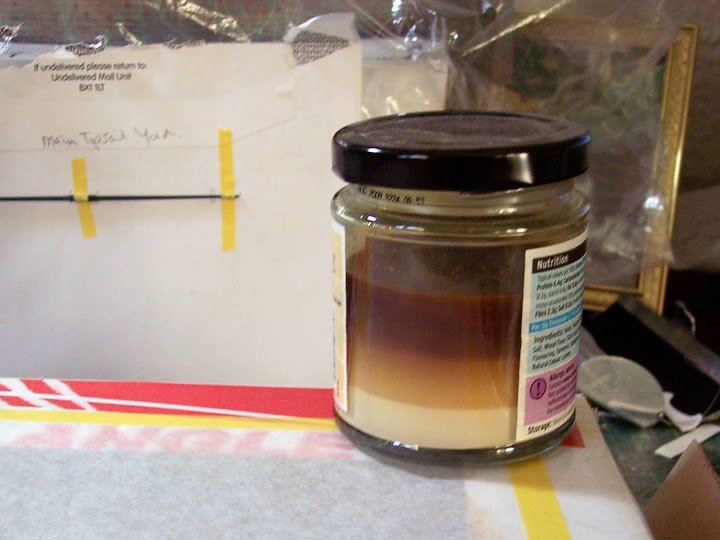
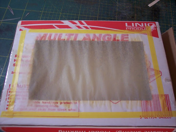
The witches brew – ear of bat, eye of toad, you know the sort of thing - actually pva diluted to the consistency of milk with a little yellow ochre paint added.
Once the potion is mixed it takes on a fetching ochre colour.
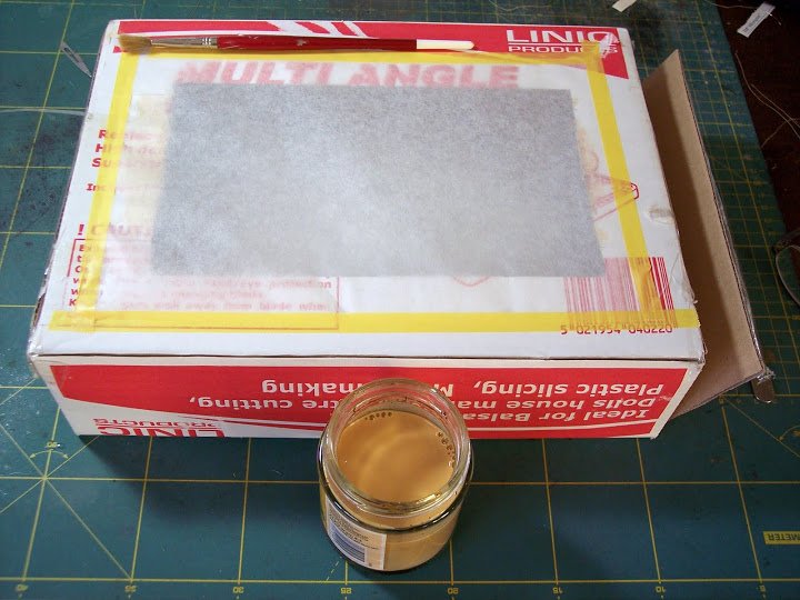
The potion being applied, note the colour change and how the tissue has started to sag.
The completed effect, just needs to be set aside to dry............. but if you’re impatient like me...
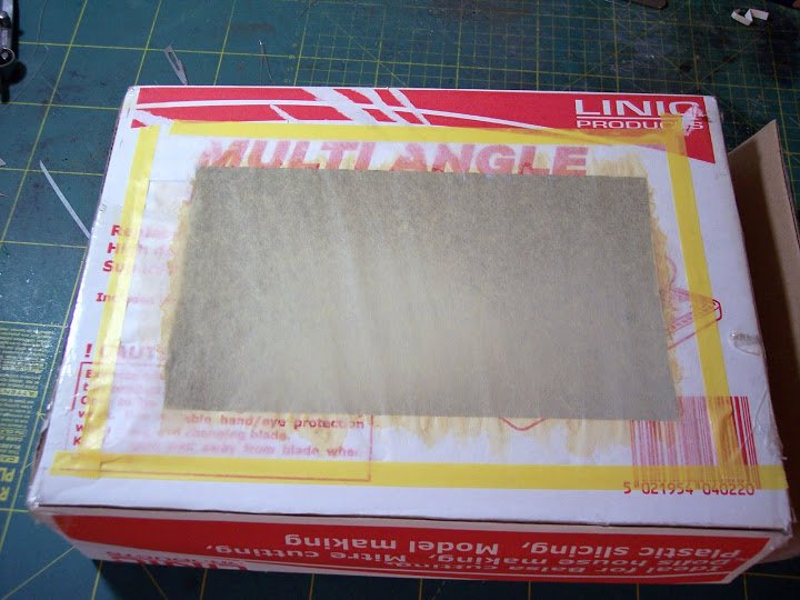
A quick blast with the CPO’s hairdryer, diffuser in place – and were ready to go.
The tissue is now as tight as drum skin and much the same colour, a little more ochery than appears in the photo.
The sail ‘material’ is removed by cutting around the edges of the hole with a scalpel, or any other such sharp implement that is to hand, and is taped over the drawing as previously made.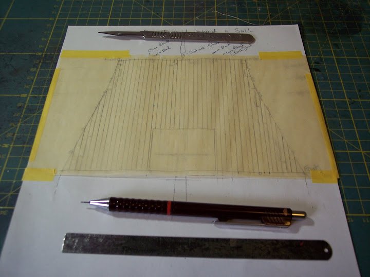
I had previously drawn out a scaled sail from the works of Jean Boudriot.
The lines are transferred and the fiddly business of making the sail up begins.
This will be the subject of the next post.
B.E.
-
Hello Dave, 2.5mm diameter stuff does seem a bit on the heavy side for Mars it equates to a 19"+ circumference cable.
According to Lees the anchor cables in circumference inches were 0.62 of the Mainmast dIameter in inches.
Another method based on older writings gives the sheet cable circumference as commonly being so many half inches as your ship's breadth in feet at midships.
It would be interesting to see what size cable comes up if you apply the above to Mars.
Something between say 11.5" and 13" circumference is my best guess for Mars, equating to scale line with a diameter of 1,5mm - 1.7mm.
with anchor cable regardless of scale I tend to go with what suits my eye, and with my Pegasus build I have both 1.5mm and 1.75mm line to decide between.
David Antscherl in ffm IV indicates a 13" cable for Pegasus (scale 1.64mm diameter line) Using the Lees factor of 0.62 of Mainmast diameter (183/8th ") it works out at 11.4" circ. = to 1.44mm diameter scale line.
As for puddening old worn rope was used in the order of 2" to 2.5" circs equating to 0.25mm diameter or perhaps 0.3mm.
So less than they indicate in the kit.
Confused? - I know I am

Cheers,
B.E.
-
Thank you Daniel, I'm glad you like it
Cheers,
B.E.
-
Hi Jason, not a very good photo but this is the spectacle plate on my Pegasus.

It is effectively just a metal band like the rudder straps, with an eyebolt secured on the outside corners to which the chain is attached.
As for chain I agonise over the scale every time I come to use it, but my best estimate for rudder chains at 1:64 for this purpose is is chain with 16 links to the inch. The chain is attached to a couple of eyebolts spaced along under the transom, to which the rudder pendant is attached and taken inboard.
Mostly models just show the chains.
B.E.
-
Hi Ian, here's the link to the model in the NMM.
http://collections.rmg.co.uk/collections/objects/66418.html
Looking at that model again it appears that she has eight swivel posts along the Quarterdeck rail, but the aftermost post on the starboard side appears to have broken off.
Thanks for looking at my Pegasus, glad you are enjoying it.
Regards,
B.E.
-
Hi Lukas, now I understand,
The absence of planking lines along the hull was the first job I attended to in the build. There is 9mm between the wales and I inscribed four lines of planking using styrene strip guides of one, two, and three widths to guide the probe, these sit against the wale edge and given the fairly small scale seem to work fine.The scribing was done with a curved Dental probe.
The butt ends were scribed in, and the grain pattern already on the mouldings reduced a little.
A jig made from polystyrene packing was used to support the hull half whilst the scribing was done.
The Wales
Fortunately Boudroit does not indicate anchor stock planking for the wales, so these were also scribed as above.
The fair run of coppering
This does present a slight problem, and looks odd to my eye the way it follows the wale around the hull which doesn’t seem to take into account any sheer.
Starting at the centre of the hull side, tape was applied beneath the wale and carried straight to the bows and stern, so it dropped below the wale by one strake at the bows and by about five strakes at the stern extreme.
Where the plating has been removed it is necessary to fill and smooth the edges and scribe planking lines.
At first sight I thought the plates looked over scale, but on checking using 4’ as a norm, they are in fact ok for length if a tad too deep.
One thing I would do differently at the outset is to glue the hawse hole sections to the hull halves so that a consistent paint finish can be achieved along the hull.
I don't think you will have any trouble putting the kit together as an out of box build, and if it's your first period ship build it may be wise not to be too ambitious with modifications. just enjoy the build and make a few changes that you feel comfortable with.
Cheers,
B.E.

Le Superbe by Blue Ensign - FINISHED - Heller - PLASTIC - Built as "Le Praetorian", after Boudriot
in - Kit build logs for subjects built from 1751 - 1800
Posted
Hi Lukas, sorry for the slight delay in replying I've been away for a few days.
I think matt is more appropriate.
Here's a link to the paint scheme on Victory.
http://www.hms-victory.com/index.php?option=com_content&view=article&id=83&Itemid=496
In terms of colour shades particularly with smaller scales I prefer to soften the black a liittle bu the adition of grey to the mix, I think it gives a better scale look.
Cheers,
B.E.