Marcus.K.
-
Posts
354 -
Joined
-
Last visited
2 Followers

Recent Profile Visitors
3,396 profile views


-
 Marcus.K. reacted to a post in a topic:
USS Constitution by dafi - Revell - PLASTIC - To Constitution and beyond ...
Marcus.K. reacted to a post in a topic:
USS Constitution by dafi - Revell - PLASTIC - To Constitution and beyond ...
-
Marcus.K. reacted to a post in a topic:
USS Constitution by dafi - Revell - PLASTIC - To Constitution and beyond ...
-
 Isn´t she a Beauty already ? (And we all know: Dafi can be a Beast when taking apart what he had build 😄 ) Wonderful add-ons !!!
 -
Marcus.K. reacted to a post in a topic:
USS Constitution by dafi - Revell - PLASTIC - To Constitution and beyond ...
-
Marcus.K. reacted to a post in a topic:
HMS Perseus by Thukydides - 1:64 - POB - Sphinx Class 6th Rate
-
 Marcus.K. reacted to a post in a topic:
HMS Perseus by Thukydides - 1:64 - POB - Sphinx Class 6th Rate
Marcus.K. reacted to a post in a topic:
HMS Perseus by Thukydides - 1:64 - POB - Sphinx Class 6th Rate
-
Marcus.K. reacted to a post in a topic:
Soleil Royal by EricWiberg - Heller - 1/100 - PLASTIC - started 45 years ago
-
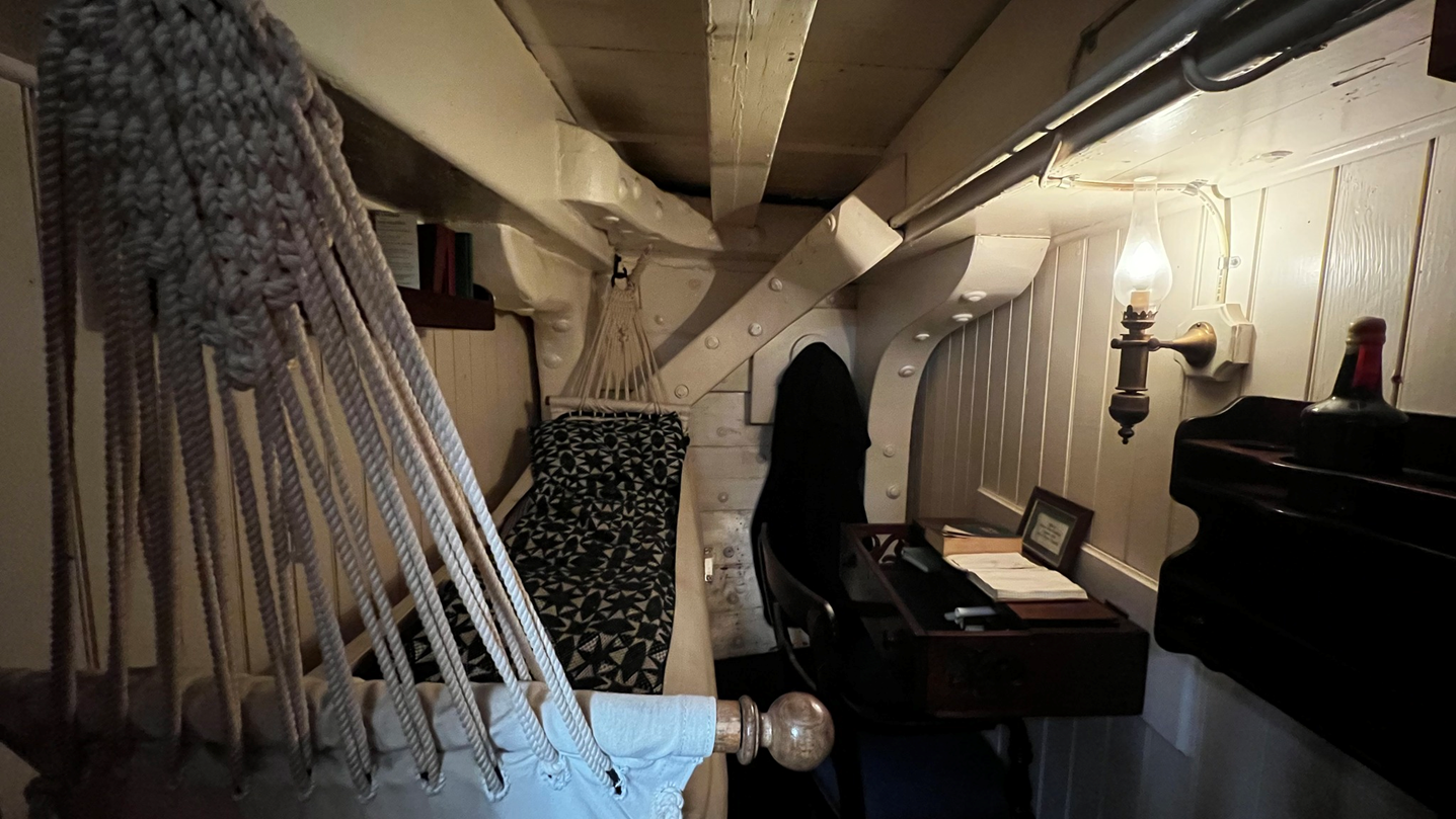
What a beautiful finding !!! Thanks for sharing. I knew those skylights from Mystic Rivers Waler Charles W. Morgan - but not from Old Ironsides. Does anyone have an idea when they were installed??
-
 Marcus.K. reacted to a post in a topic:
Constitution "Mystery Skylight"
Marcus.K. reacted to a post in a topic:
Constitution "Mystery Skylight"
-
Marcus.K. reacted to a post in a topic:
Pomeranian Rahschlup 1846 by wefalck – 1/160 scale – single-masted Baltic trading vessel
-
Marcus.K. reacted to a post in a topic:
9 Pound Naval Cannon 1786 by AON - FINISHED - 1:12 scale
-
mtbediz reacted to a post in a topic:
USS Constitution by mtbediz - 1:76
-
USS Constitution by mtbediz - 1:76
Marcus.K. replied to mtbediz's topic in - Build logs for subjects built 1751 - 1800
Beautiful! So, there is a weight compensating the shortening of the rope you produce in yor maschine? -
Ras Ambrioso reacted to a post in a topic:
Pomeranian Rahschlup 1846 by wefalck – 1/160 scale – single-masted Baltic trading vessel
-
druxey reacted to a post in a topic:
Pomeranian Rahschlup 1846 by wefalck – 1/160 scale – single-masted Baltic trading vessel
-
Keith Black reacted to a post in a topic:
Pomeranian Rahschlup 1846 by wefalck – 1/160 scale – single-masted Baltic trading vessel
-
wefalck reacted to a post in a topic:
Pomeranian Rahschlup 1846 by wefalck – 1/160 scale – single-masted Baltic trading vessel
-
We do the same in automotive display production. In classical LCD displays (I know, two times "displays") there was that effect we call "Mura". That are visible "clouds" of grey in intended black areas caused by stress in the display's plastic housings. To get rid of that stress and to get the assembly settled they are placed in an oven of also about 70° C for enough time so that the plastic adjusts to the stress.. and Mura dissapears.
-
The Bitter End reacted to a post in a topic:
USS Constitution by The Bitter End - Model Shipways - 1:76
-
Der Alte Rentner reacted to a post in a topic:
USS Constitution by The Bitter End - Model Shipways - 1:76
-
Thukydides reacted to a post in a topic:
USS Constitution by The Bitter End - Model Shipways - 1:76
-
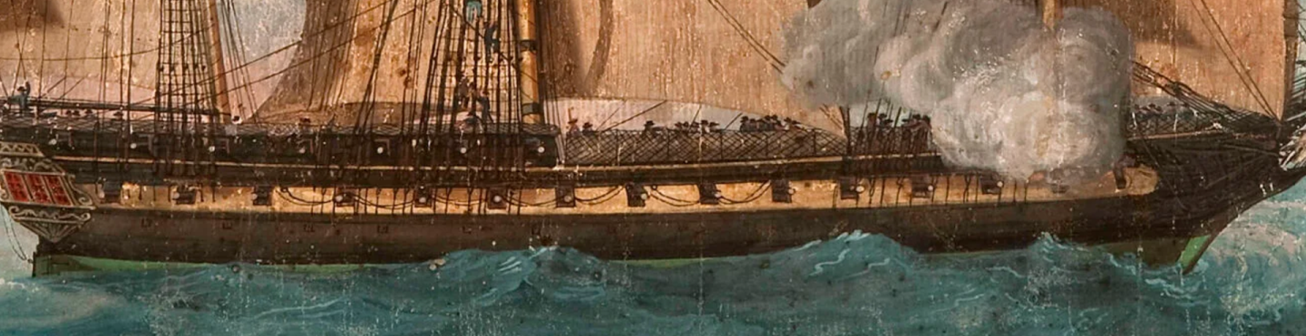
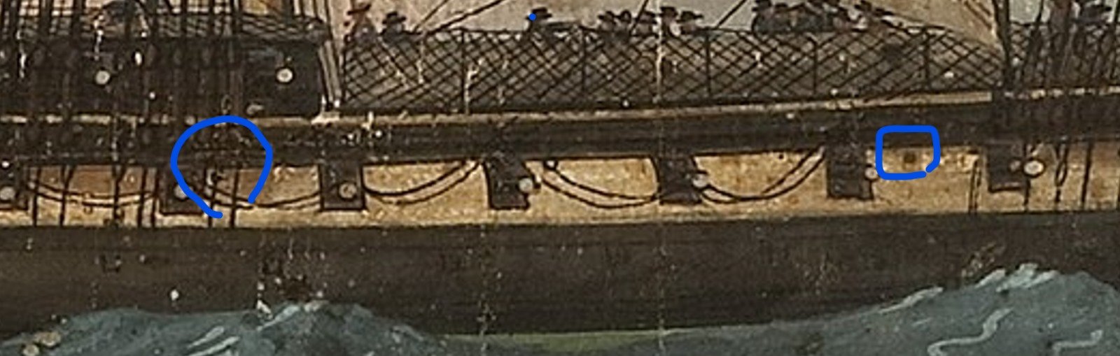
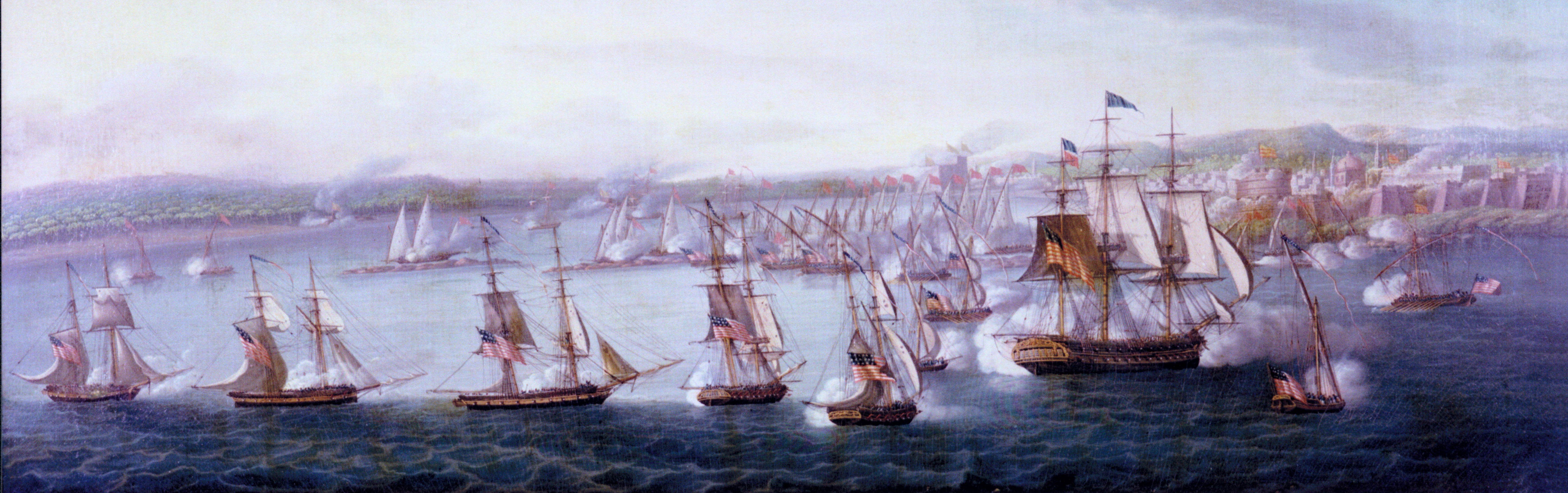
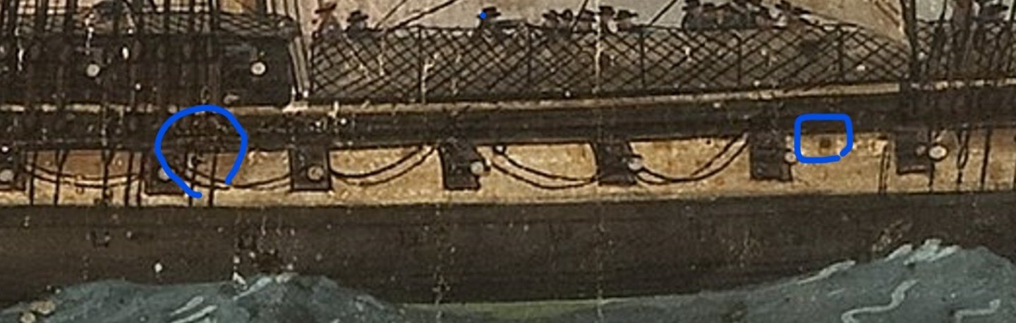
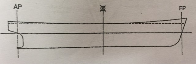
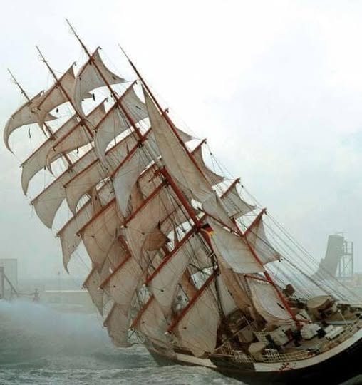
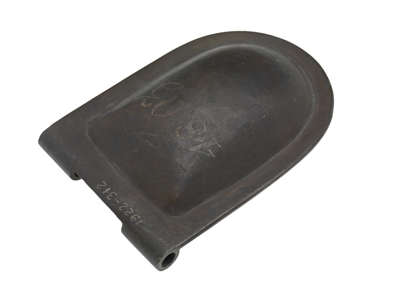
I had to search for it myself.. The reference for the 16 cast scuppers is only in my paper-version of Tyrone Martin´s "A Close up" from 2008. It contains a bit more information than the online version from 2003. What may be a "casted scupper"? This is an example of a casted part, which might have been what the text talked about. The shown lid is a casted "scupper valve" found in the collection of the Royal Museum Greewich. But of course the "cast scupper" may also just refer to a stub end of the scupper - made as cast part. But as the "casted scuppers" are mentioned to be fitted in 1814 we may assume that previously to that date there wasn´t any "casted" part. Which allows Haiko - pointing on the 1797 status - to not need to guess or show anything like this - but the scuppers as openings, material unascertainable for now. Could be lead, could be iron ... Why only in the center of the ship - around the ship´s waist? .. in most of the cases the waist of the deck is usually the most deepest point on the deck Principle sketch of a deck´s sheer - midship being the deepest point where water would flow to .. And also the side´s lowest point is in the region of the waist - due to the shape of the hull these are the lowest points on downwind sides of the ship in case of stronger winds. Now guess where the "deepest" point of the deck is right now? Where would you need the scuppers now? (Flying P-Liner: Pamir in 1905) For USS Constitution we think we also saw hints in Cornè´s 1803 painting we used as a reference: Here you see a detail view on the painting. Marked with blue are 2 "dark spots" - which are in positions we see as comparable with Roux´s President Paintings. The left one being just below the main channel, the forward one between gun 5 and 6. Just the center one would be .. either a) missing in the painting by accident .. or .. b) that ring we see where that rope runs through, was a misinterpretation of Cornè in his sketch - c) wasn´t THERE .. and we had only 2 scuppers in the spar deck level - and 6 in the gun deck level. As c) seemed not very likely - you would want a scupper in the center! - we decided that a) or b) are valid .. and therefore there would be an opening needed in between those two dark spots .. Haiko marked the spot: Funny coincident: that ring in the center? ... is were we would expect a 3rd scupper?.. right? Hm.. option b) most likely? As we by now have found 3 positions - comparable to Roux´s President - we can assume the other 5 scuppers to be placed somewhere on the gun deck level as we see it in the Roux paintings - even if we can´t see them in Cornè´s painting. They would be a bit lower where the gun deck itself would be. And they might be - just as Roux shows it - one plank above the air vents. This is (partly) a very weak chain of evidence, we agree .. but .. its the best we can offer for this essential feature for now.
- 233 replies
-
- 3
-
-
- Model Shipways
- constitution
- (and 5 more)
-
Thukydides reacted to a post in a topic:
USS Constitution by The Bitter End - Model Shipways - 1:76
-
I was checking in my Robert Gardiner´s "Frigates of the Napoleonic Wars" .. and we can find there examples for a) ships with ports for rowing the ship - like on page 16: HMS Hyperion (1806) .. here a view on her frames - and you see the ports for the oars being in the level of the gun ports: https://www.rmg.co.uk/collections/objects/rmgc-object-82795?_gl=1*10vq9vc*_up*MQ..*_ga*MTM1NTE2MjQyOS4xNzYyOTc2MTQ3*_ga_7JJ3J5DBF6*czE3NjI5NzYxNDYkbzEkZzAkdDE3NjI5NzYxNDYkajYwJGwwJGgw*_ga_4MH5VEZTEK*czE3NjI5NzYxNDYkbzEkZzAkdDE3NjI5NzYxNDYkajYwJGwwJGgw Here the inboard profile - including the ports for the oars: https://www.rmg.co.uk/collections/objects/rmgc-object-82796?_gl=1*d508ay*_up*MQ..*_ga*MTUwNTQxMzg5MS4xNzYyOTc2MzMy*_ga_7JJ3J5DBF6*czE3NjI5NzYzMzEkbzEkZzAkdDE3NjI5NzYzMzEkajYwJGwwJGgw*_ga_4MH5VEZTEK*czE3NjI5NzYzMzEkbzEkZzAkdDE3NjI5NzYzMzEkajYwJGwwJGgw https://collections.rmg.co.uk/media/2/440/699/j5940.jpg The ports are much higher than what we see in Thukydides´s findings.. So the ports in HIS examples are very likely NOT for oars. b) air vents .. there are ton´s of examples with air vents in the berth deck level. A lot of them having most of the air vents in the rear section of the berth deck - where the midshipman staterooms would be in case the officiers had their quarters on the gun deck - in front of the great cabin. there are examples in which we see air vents in the rear section - but also in the mid and even the forcastle area - on berth deck level. One beautiful example is on page 28. A profile drawing of a Lively class ship build in 1799. Another example is on page 156 - a painting of HMS Phoenix .. in which we see open air vents in the belly of the ship.. I admit - not too much examples .. One thing we may think about: in Constitution the crew was sleeping in the Berth deck - and 400 man need some air ! .. I am not sure about the sleeping area on smaller british Frigates? But for sure the first getting the luxury of fresh air would be the gentlemen in the staterooms, right? The ordinary seaman usually did not have to expect a lot of attention for his well being. That might also be a reason why we so often see air vents in the stern area - but not in the forcastle. Interesting...
- 233 replies
-
- 1
-
-
- Model Shipways
- constitution
- (and 5 more)
-
Thanks for your kind comment, Thukydides. Are you sure we see air vents here? They seem to be higher than the deck? Is it possible that these are ports for oars? The ships seem to be smaller and may have been moved by the help of oars? For them these positions would fit - except: why not having more then ... Interesting comparison.
- 233 replies
-
- 1
-
-
- Model Shipways
- constitution
- (and 5 more)
-
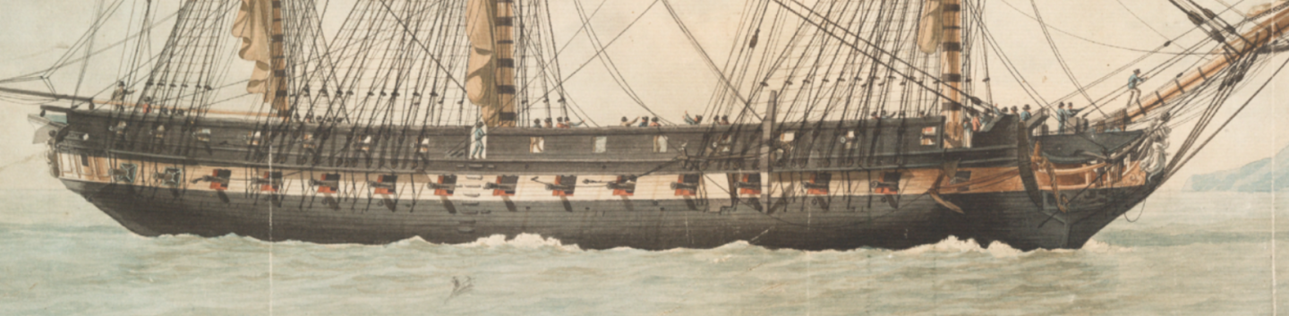
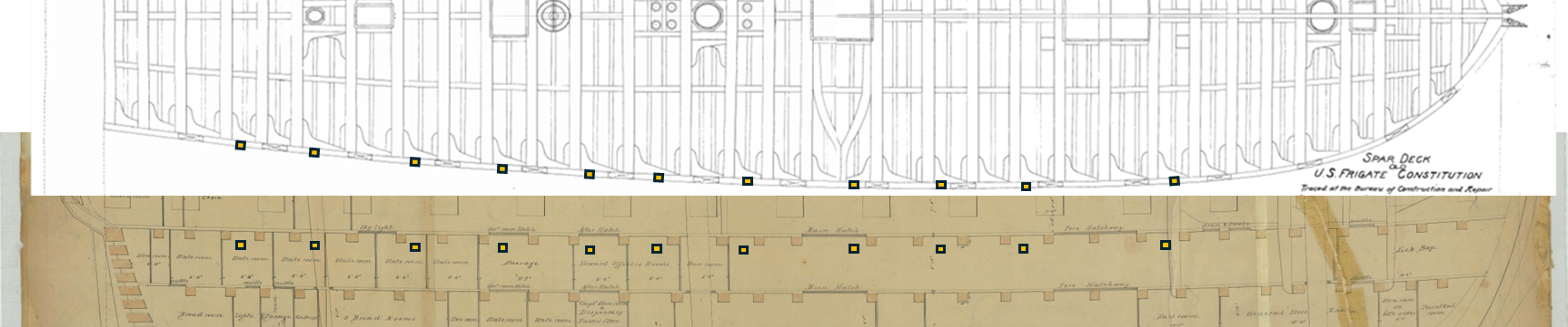
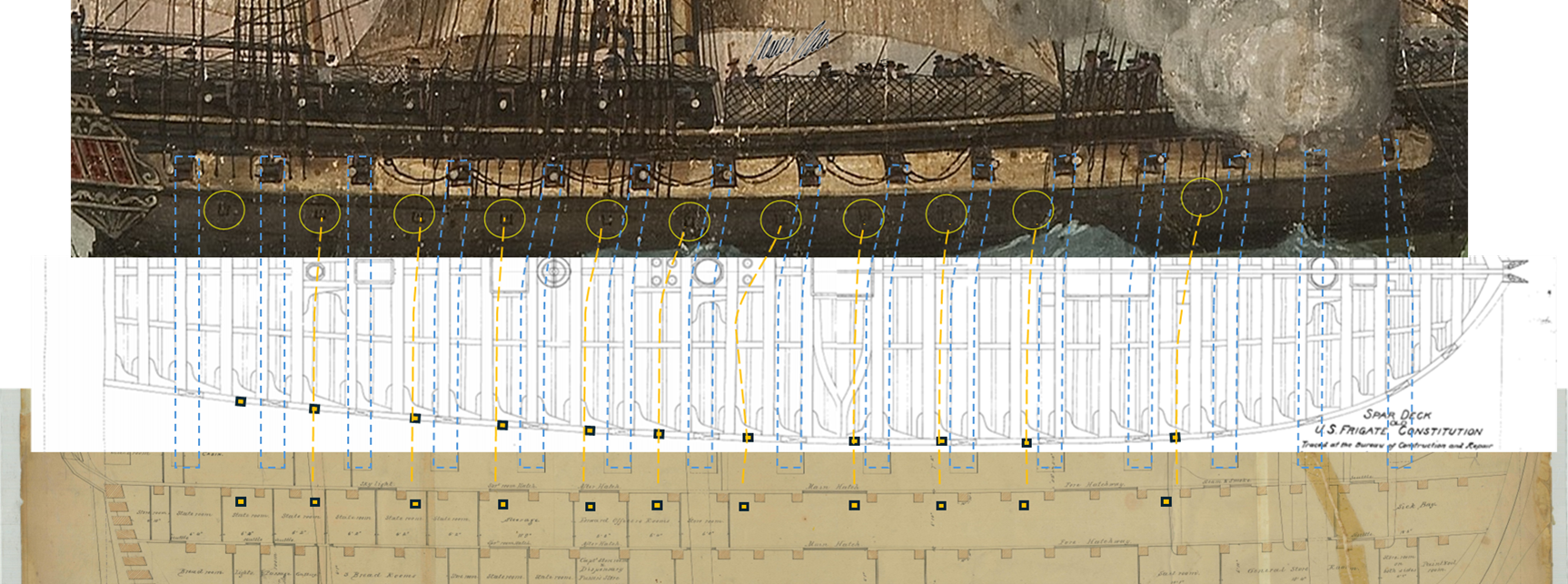
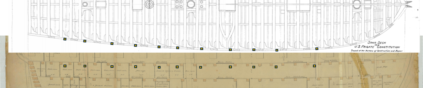
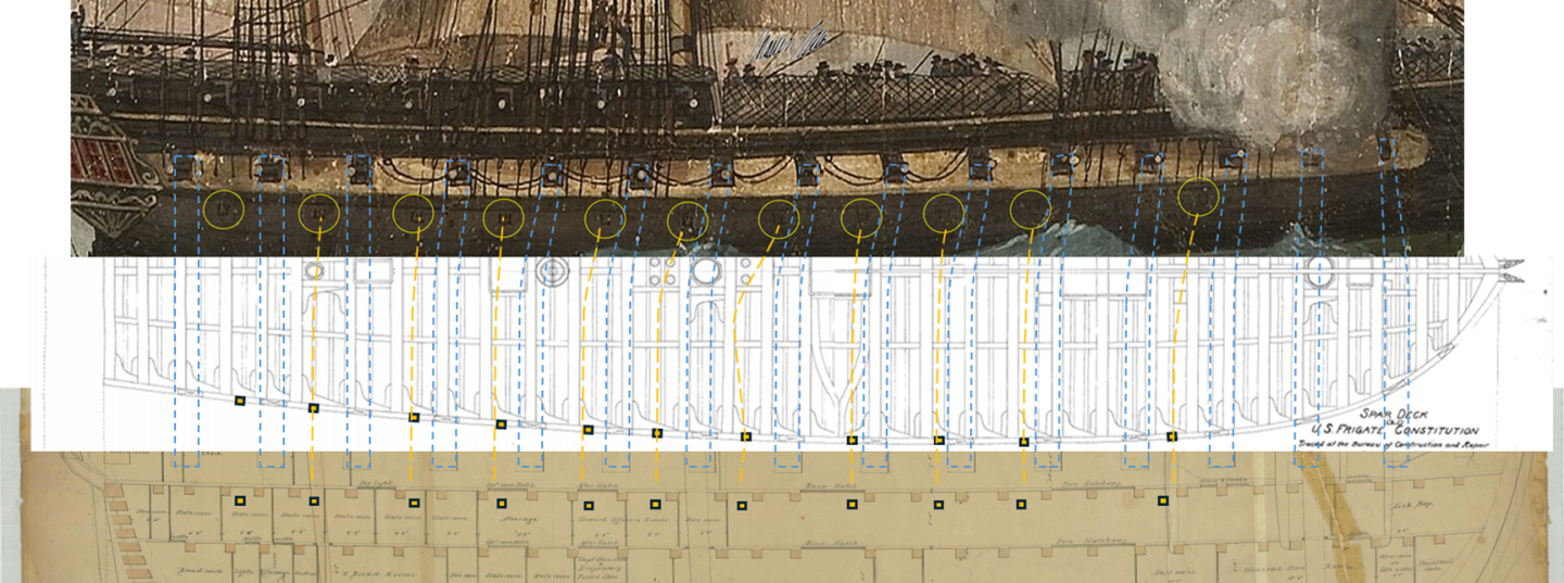
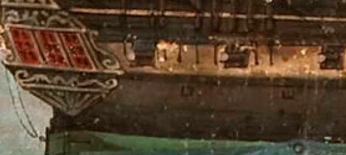
Wow, I saw some of the photos before in WhatsApp - but here on the PC things look so much better. I have to thank Haiko a lot: accompaning his build is a huge pleasure and his questions are challanging and motivating to digg deeper and think further. More than once his questions forced me to cross check my interpretation of things and due to his hints - partly caused by issues in building the model, partly because he had found historical evidence I did not recognize before - we managed to have a better understanding of what might have been, and what may be not that much likely. One of the most interesting experiences is, that in adding discussed features on the model, the technical interpretation seems to shape a more balanced and more likely representation of the ship than we believed when we theoretically discussed these features. That is a fascinating process. Lets start with the "air vents". William Bass in his beautiful book "Constitution - Superfrigate of many Faces" did investigate the ships "2nd phase" - between 1803 and 1808 by analyzing Cornè´s 1803 and 1804 paintings .. Especially in the 1803 sideview - a painting which was done purely to show the ship under sail. He obviously saw and tried to represent these "squared things" - as Bass called them later - on the ships hull in this painting. Bass discussed those with Cmd. Tyrone Martin - and as the former captain of the ship did not believe in Air Vents - due to their "too high" position and due to the several times mentioned actions of adding more air vents (although their numbers and places are not very good specified) in the ships logs Bass proposed this idea of seeing here squared "washers" and a centering bolt & nut which might be iron stiffners crossing the hull. Cmd. Martin did not believe in this theory either. But he did not propose any better interpretation. Antoine Roux, a well known french artist, did generate - beside hunderts of other maritime paintings - several representations of US Frigate President. Beautiful paintings showing so many detailed features! And here we clearly see Air Vents - some of them even opened - in about the same height as what we believe to see in Corne's tiny painting. And if we make use of a Lord Section cut and compare the postion in Cornè´s painting with some of Roux´ USS President paintings, we might assume the position as shown here: The yellow marked thing being the lid - and the opening being just below the Gun Deck ceiling. That would - in our opinion fit pretty good with what we see in Cornè´s painting - at least for the height. The positioning of those possible air vents is a different story. One of Cmd. Martins doubts may be caused by the densed place in Berth deck due to so many knees - which would interfere with possible openings. This photo from USS Constitution´s facebook page (https://www.facebook.com/photo/?fbid=10158391010821741&set=pcb.10158391011666741) gives an impression of the room at the ships hull in berth deck level - as there are vertical ("hanging"), diagonal and even longitudinal knees along and below the gun deck beams. The only thinkable room is above that diagional knee, right? So we needed to figure out: where might those have been positioned? There are 3 drawings existing which help to understand the position of deck beams and even the knees in the early ship. Two of them are drawings by a Samuel Pook - done in 1847 and one in 1849 - profile inboard drawings - showing clearly the deck beams. .. and even older: Waldo´s 1817 deck plan. A comparision of both showed, the deck beam position did not change (at least not much of them) and the deviation between both in the foreship is most likely to be explained by distortions due the several times copying and possible issues in digitalization. For us that is evidenve, that we might trust all three of those plans - at least for the position of the beams. The Waldo Deckplan revealed even more: you can see the horizontal or "longitudinal" knees and the diagonal ones - and if you compare all that, you can estimate where there is room for possible air vents: if you place the air vent opening always below the horizontal knee - just in front of the beam behind that, you should be fine. The orange squares should show that. An odd thing we noticed: nearly all longitudinal knees in Waldo´s drawing are pointing forward. No switch in the center? And: those positions match with Cornè ... Well, they match in a degree which seems plausible. If we place all those views together, we notice that Cornè seems to have had a problem in perspective - but .. the deviation of the gun ports match with the expected deviation of the air vents: It is interesting to note: in non of the paintings - especially in the very detailed Roux representations - we see a feature as a hinge or an opening mechanism. A hinge it must be, as in the french painting the open air vents open like a door - sideways. But obviosly the mechanism was hidden from view - maybe because any outside visible metal feature might be endangered as to position is within the most critical area of the wales, where you can expect contact with other objects.. An extruding feature would be damaged soon! We may be wrong with all this .. but for now we can not see a major "no-go". And even the several times described addition of more air vents in the ships log is still possible. As the above status of 1803 still has gaps in the ships forecastle. We saw that the deck beams are represented in the same positions in 3 drawings in 3 different years. Those seem to be a fact. The function of this "feature" visible in Corne's painting seems to match with something in another artists interpretation on a sistership. The vertical position seems to fit in function and needs (as far up as possible in berth deck to avoid as much as possible accidential entry of water). The longitudinal position in Corne's painting is traceable into the drawings. In our opinion it is more likely to follow this logic, based on observations, comparisons and evidence and therefore generating a certain likelihood, than beliving in any other purely guessed number, position or interpretation of those "squared things" as Bass called them.
- 233 replies
-
- 2
-
-
- Model Shipways
- constitution
- (and 5 more)
-
WOW - wonderful build ! I wonder why nobody left a comment? The result is amazing and fun to study. Those hundreds of details ! Love it!! Concerning Marquardts AotS Constitution: I can not often enough emphasis to be careful with his - I agree : beautiful ! - book. As therein lies the danger. Everything seem so perfect and professional - but still: in my (humble) opinion that book deserved a better investigation. The drawings contain a lot of assumptions for which I think it will be hard to find evidence. He missed many well known details and showed them in a wrong way - and due to the beauty, the price and therefore the success of that book many modelists are fooled. The so build models may be masterfully build beauties! Its just: if the builder is interested in historical accuracy and learns later on about the incorrect details he/she might be frustrated. And I expect more by an authority like Marquardt than that. But on the other hand: every model is the mirror of those days knowledge and expertise - and each model is getting better and better. Your model, @Strand , is a unique beauty and I hope your "employees" are careful enough to try to play with the model!? For the rigging I would recommend "all Sails up and flying" by Olof A. Eriksen. Its a bit hard to read - as Mr. Eriksen´s style is a bit .. strange and uncomfortable to read. Partly because he is (as me and you) not a native englisch speaker. But also - and maybe even more - because he is very, very, very sure about his opinion and that makes reading hard. Also his drawings are done with much less professionalism than Marquardts - and all that is causing a certain "disrespect" vs. his work. The book is very expensive and what you get for that amount of money looks a bit odd - especially compared to books by Ancre for example which are in the same price range but are produced in a so much more professional way. But I think his work is underestimated by too many. In a comparable way Marquardts AotS-Constitution is overestimated. Here the unknown, strange writing and unprofessional producer of manually done drawings with nearly no reputation - who did a deep and profound investigation in a very slim field (the rigging of Old Ironsides in 1815) - and there the recognized authority with a huge, profound and wide knowledge in maritime history and with professional graphic designers and perfect expression of english language - who did make use of his profound general know how in maritime technologies and obviouly did not go too deep into research of the subject of this book. Who will win the respect of the audience? I myself never did go into details with rigging - but the way Eriksen describes how he determined his interpretation (and that´s what it is - even if he states that all his findings ARE true facts!) seems to me to be very plausible and reasonable. He recreated the rigging of the late 1812-15 ship - based on several sources and compared each source even by "trials" on his model. In a way a modelists experimental historical research. I like that approach. On ships everything had to be functional and practically working. Another beautiful - and less expensive ! - book - but describing the British rigging of smaller frigates: Lennarth Peterrson´s "the Rigging of Period Ship Models". A very beautiful book for everyone building a frigate or another square rigged ship - even like the HMS Flirt. Of course this is not 100% reflecting the rigg of USS Constitution (in that maybe comparable to Marquardts AotS-book which you got already) - but it describes the functions of each rope usually needed - and even if the Americans did have some of the lines in different directions and positions, it would be a useful reference. Looking forward seeing your next steps !! And your plans for future projects are just as interesting as this one. Have fun!
-
I just noticed, that I misused the wrong thread here - this is about Steels "masting and rigging" while I looked for Plates in Steels "Elements and Practices of Naval Architecture" - another of Steels obvoiusly many books about naval affairs.. Nevertheless: let me point on another interesting finding: https://archive.org/details/mobot31753002007406/page/XV/mode/2up What you see directly is above´s plate - which Kris so kind shared. The following pages showing more interesting details of british Men-o-war - including a development of the ships hull planking .. VERY interesting stuff. These seem to be plates similar / comparable to Steels plates in above mentioned Steel´s "E & P of Naval Architecture" - but collected by a Rev. Abraham Reed. His Encyclopedia can be found here - and in the bottom of that article you will find links to "digital copies" of many of his collection! https://en.wikipedia.org/wiki/Rees's_Cyclopædia Enjoy!

-
Why didn´t I notice this one !? THANKS a lot Kris ! This is what I needed to see!! As I wanted just to learn the names of things I don´t care about the lines. So the poor flatness does not matter to me. THANKS A LOT !
-
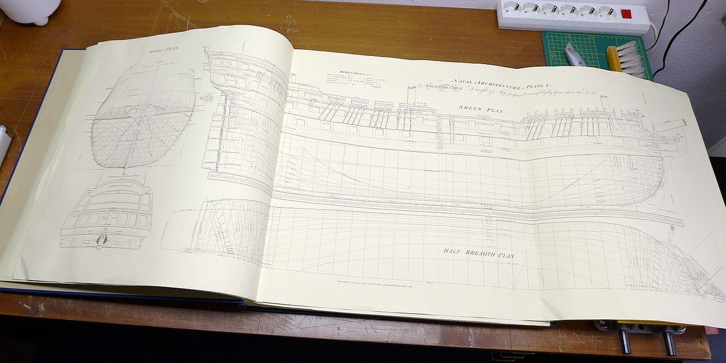
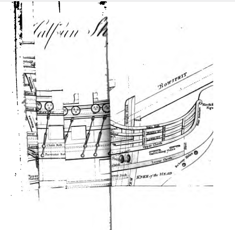
The links above don´t work anymore - but there is a 1822 version in here: https://archive.org/details/elementspractice00stee/page/n17/mode/2up And here is an even 1812 version: https://www.google.de/books/edition/The_Elements_and_Practice_of_Naval_Archi/TWsmw-QqvmAC?hl=de&gbpv=1 I am looking for a good digital copy of plate I - which seems to show details of the hull´s structure and provides a nomenclature for those elements. I found that in the many AotS books I own the authors use very different and sometimes even conflicting names for the same elements. So I looked for advice in contemporary books. But plate 1 of David Steels "Elements and .." seems to be a foldable wider page - which as it seems may have been published in an extra "booklet" or folder - and which seems to be not scanned. I found one photo of that page I was from a rare 1977 reprint of that book - including the plates - but unfortuantly not readable in this photo: Source: https://www.segelschiffsmodellbau.com/t6107f1246-Steel-David-Elements-and-Practice-of-Naval-Architecture-England.html#msg239479 I found a scan in another of Steels book .. it may be the same content as this Plate 1 - but obvously it wasn´t scanned unfolded: Its from modelshipbuild.com ´s collection of old books: Steel´s Vade Mecum of 1805. https://modelshipbuilder.com/publications/pd/PD_vade-mecum_steel.pdf Does anyone have a clear readable digital copy of this plate he can share with me?
-
Wales
Marcus.K. replied to -Dallen's topic in Building, Framing, Planking and plating a ships hull and deck
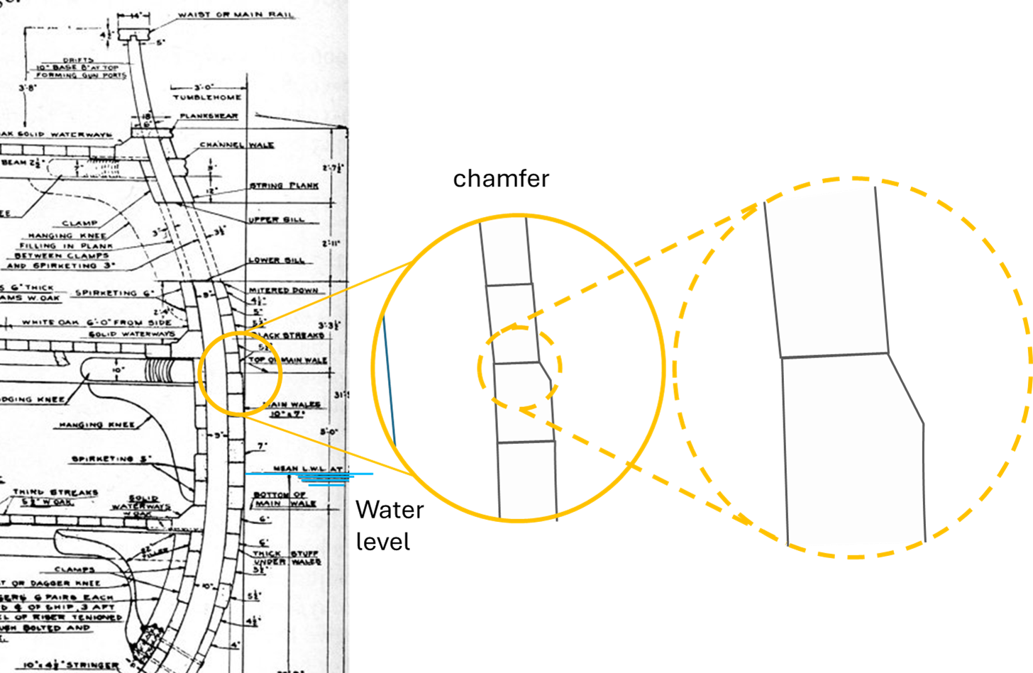
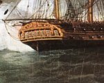
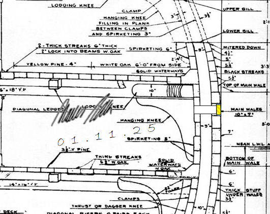
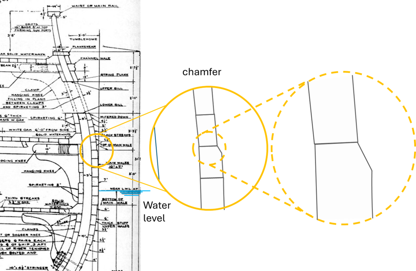
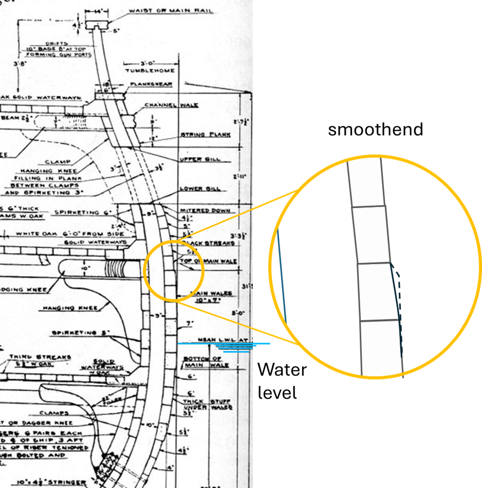
Gentlemen, still digging into this tiny little bit of detail .. but recently found more evidence for the existance of a "visible" thickness change of the wales vs. the planking - even if there is "thick stuff" beside the wales - planks which are thicker than normal hull planks: This is from David Steels "The elements and practice of naval architecture" - the 1822 version .. and it seems the wales are noteable thicker - I guess the corner might be a bit "chamfered" .. but the edge and the thickness-change are really notable. There would be a "line" .. And - I have to appolgize - there is something I did not see before .. Cornè´s side view of USS Constitution in 1803 shows clearly a top and a bottom "edge" of were we believe the wales have to be: Can you see the color shift? .. This seems to be the wales in 1803 on the ship.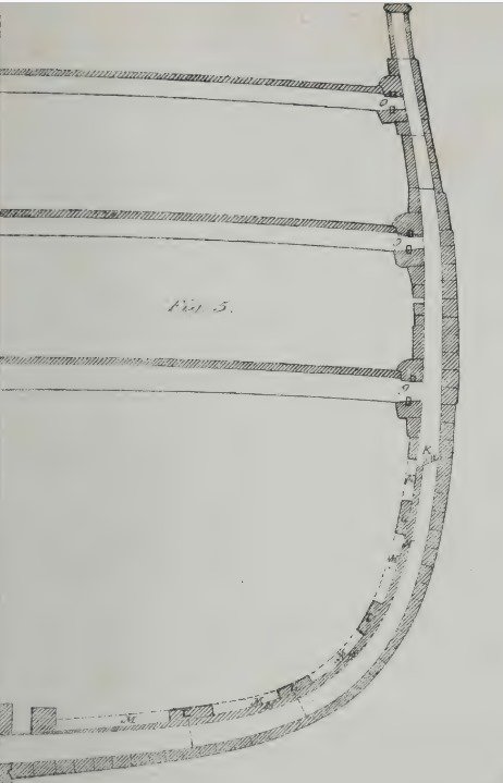
-
Wales
Marcus.K. replied to -Dallen's topic in Building, Framing, Planking and plating a ships hull and deck
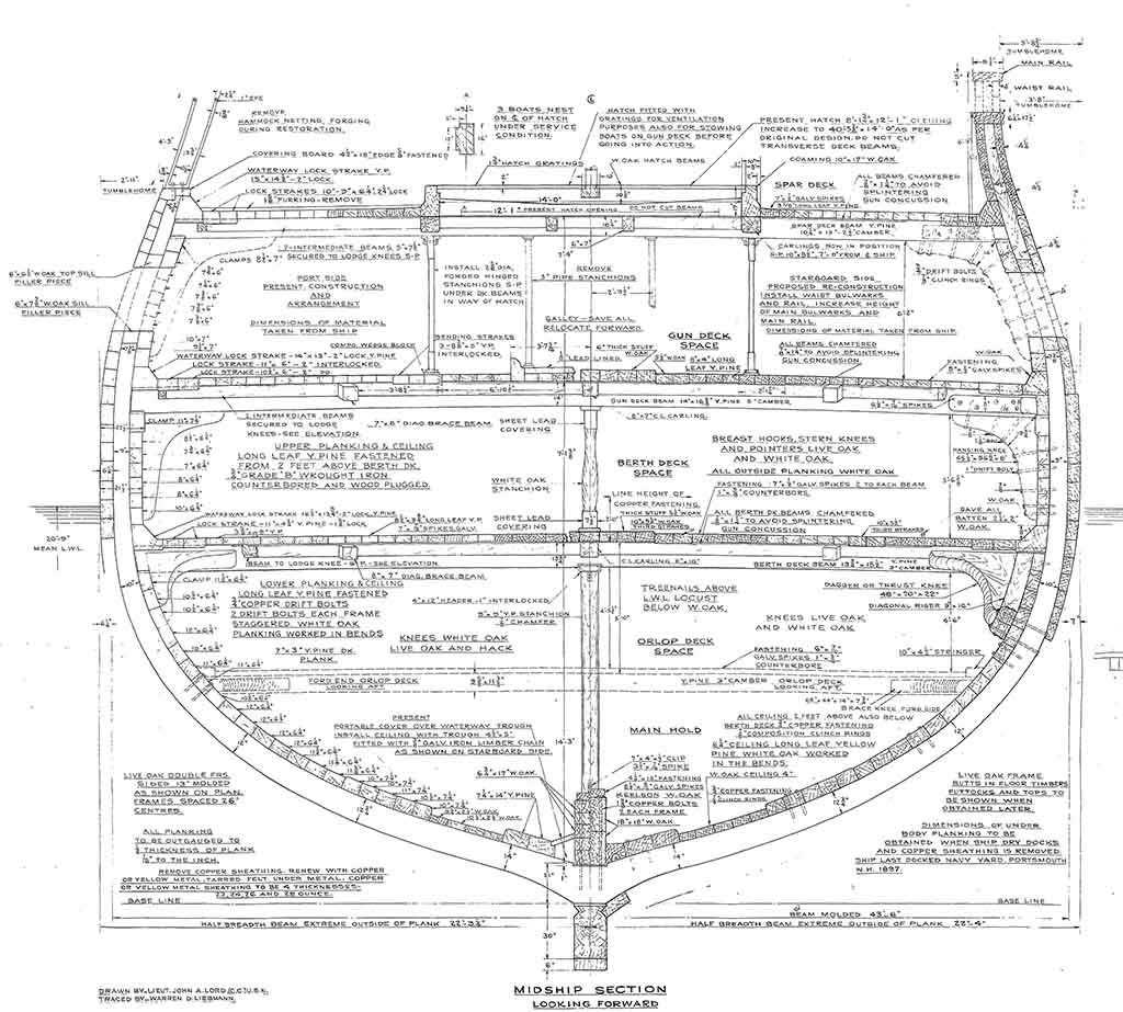
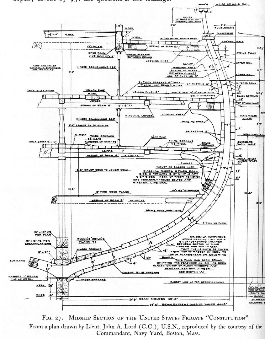
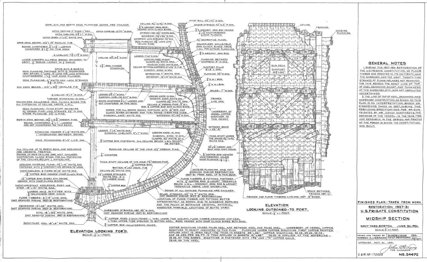
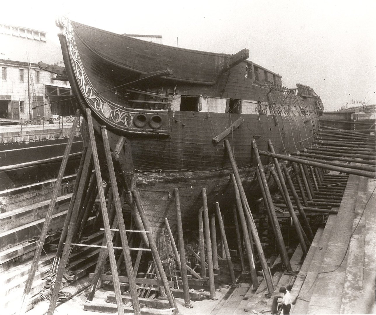
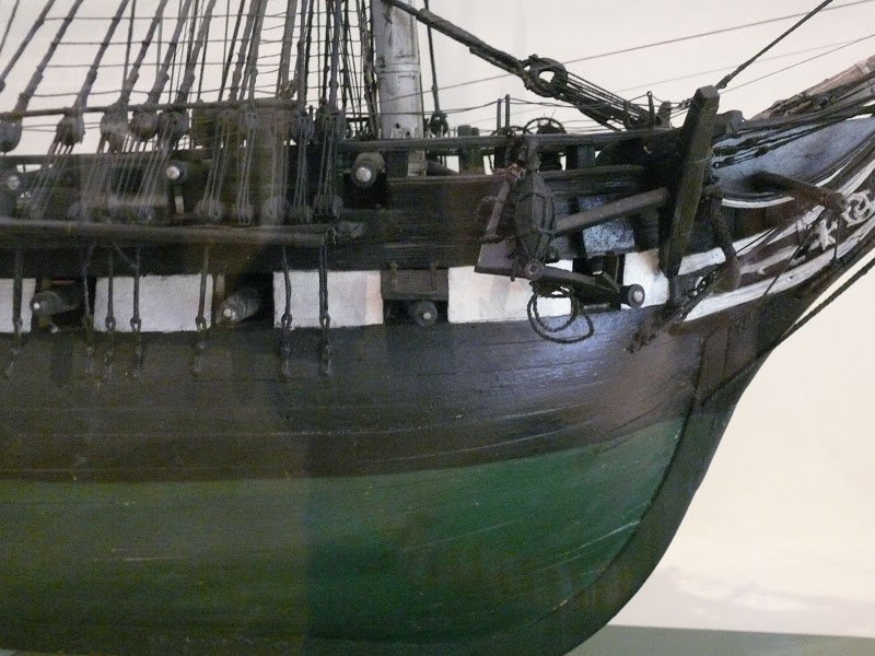
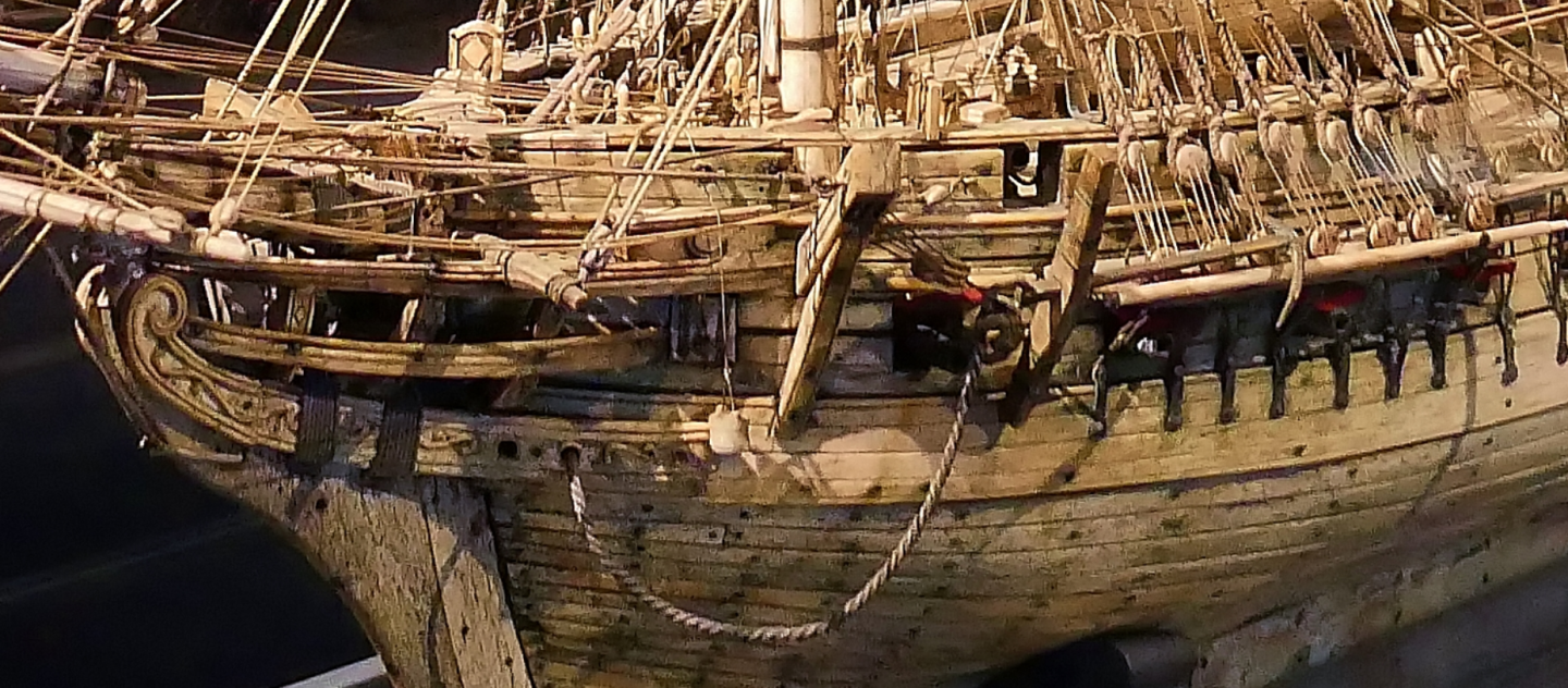
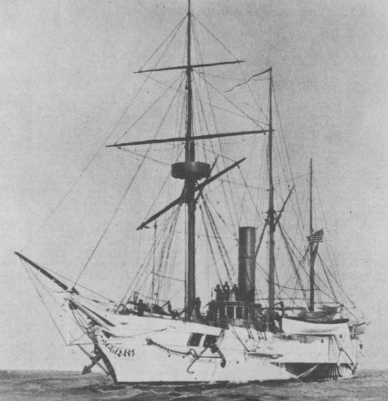
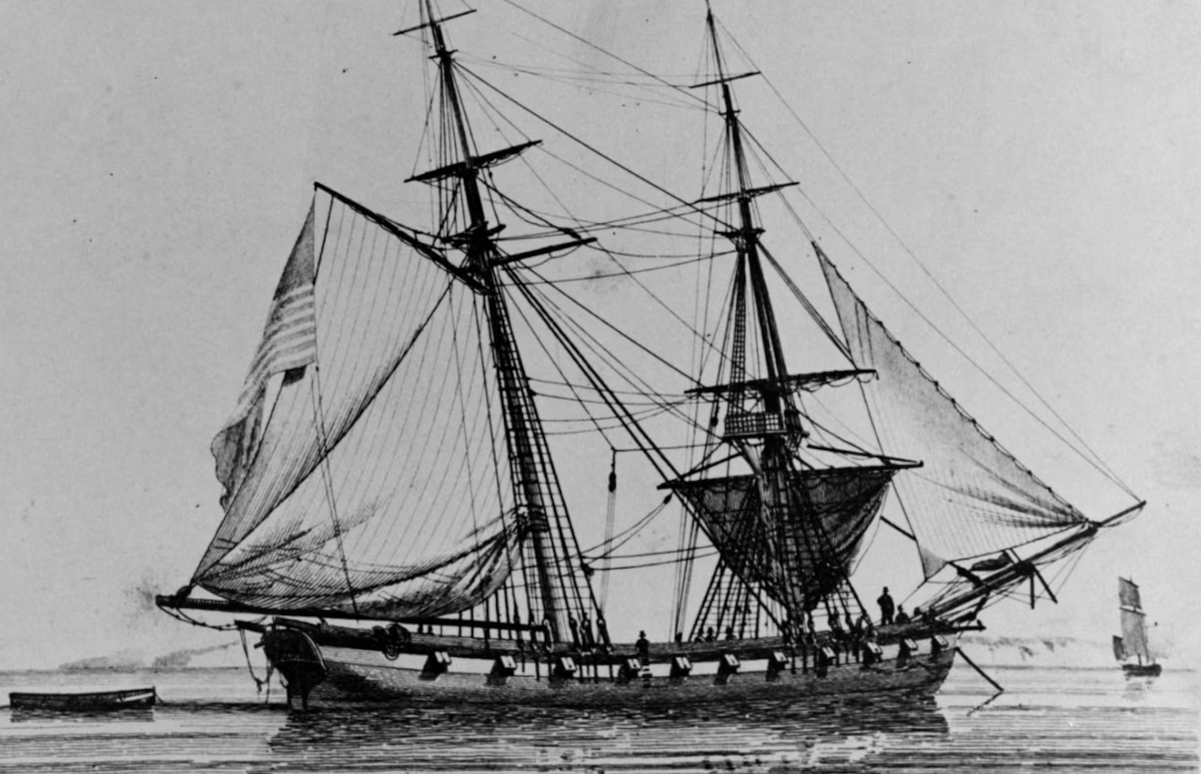
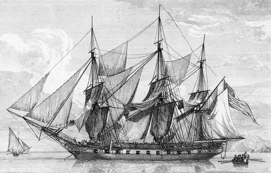
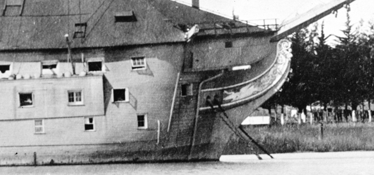
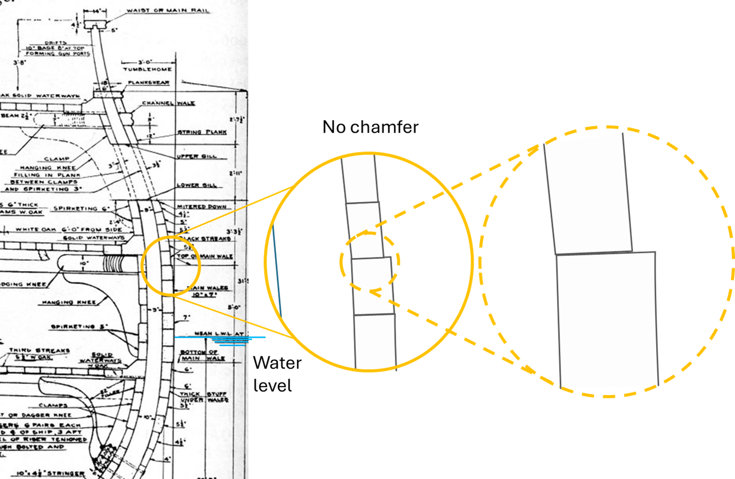
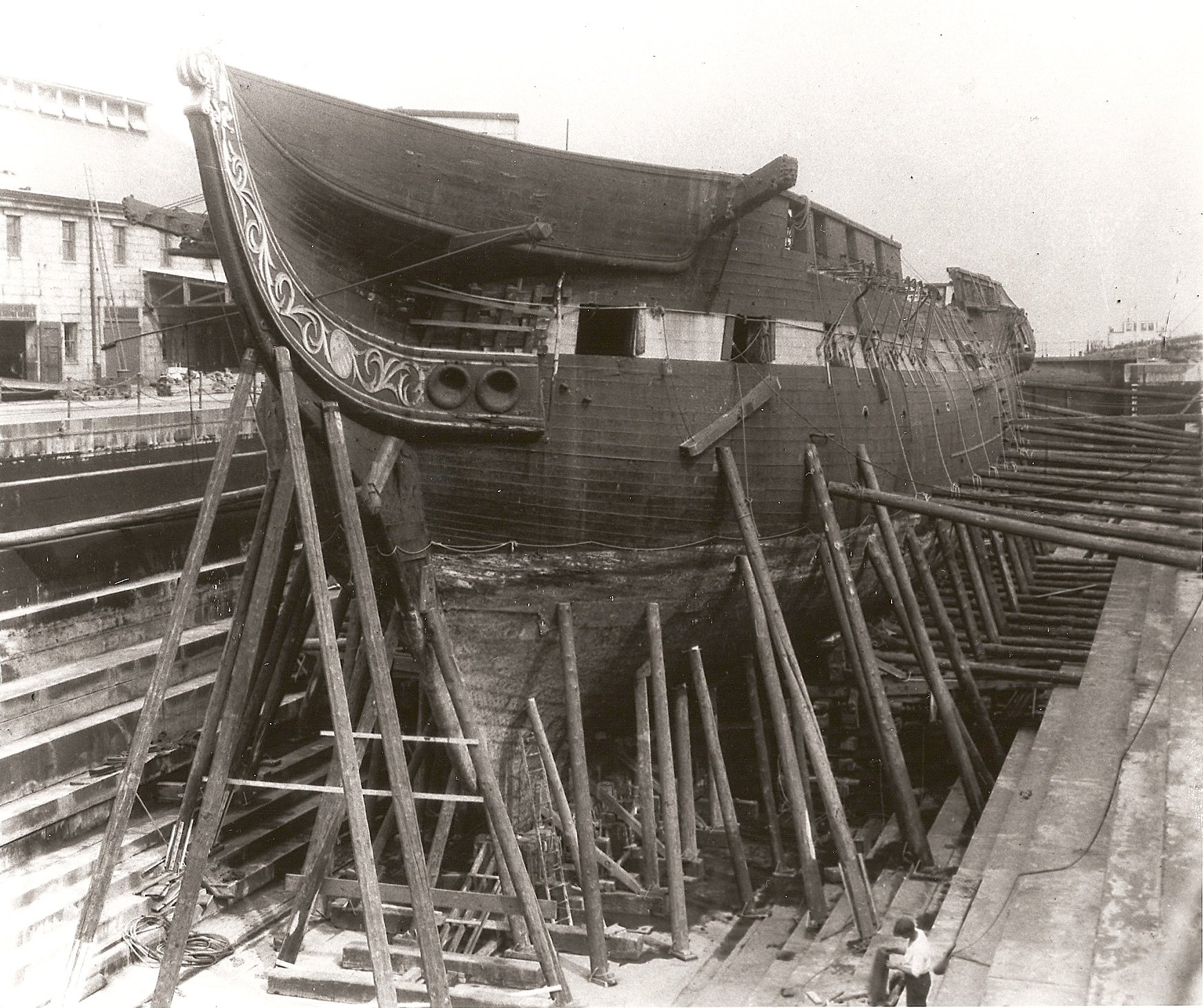
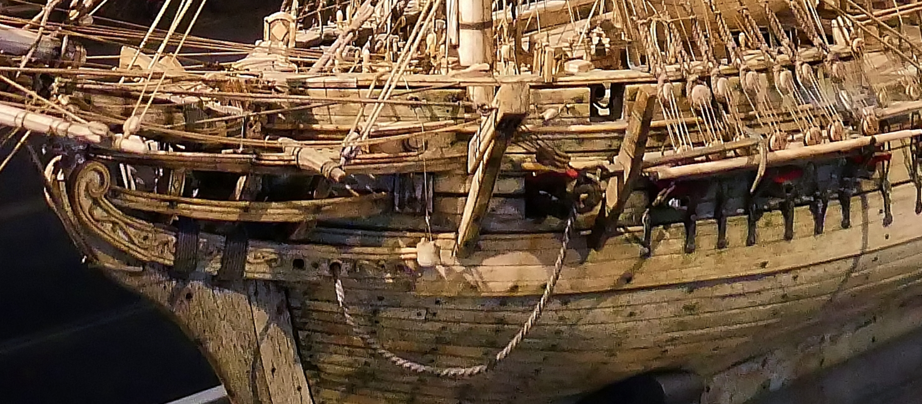
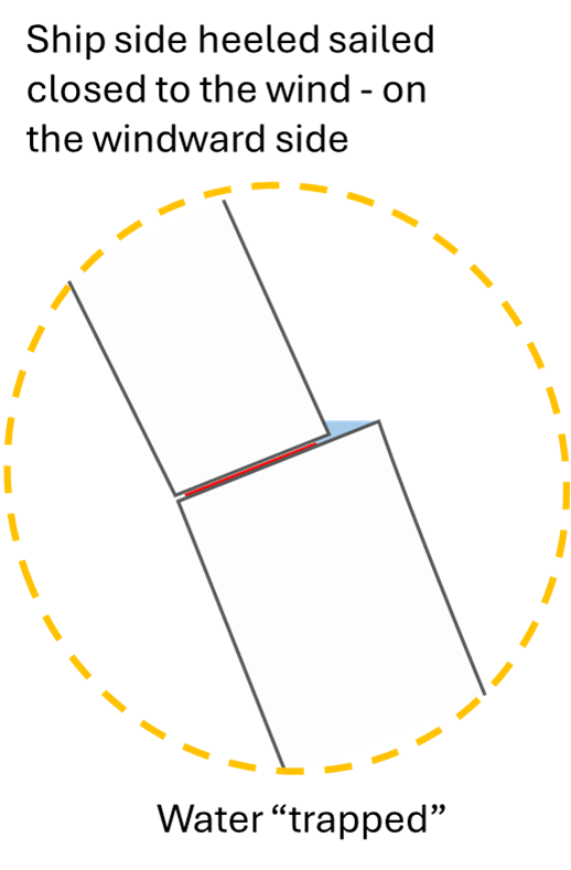
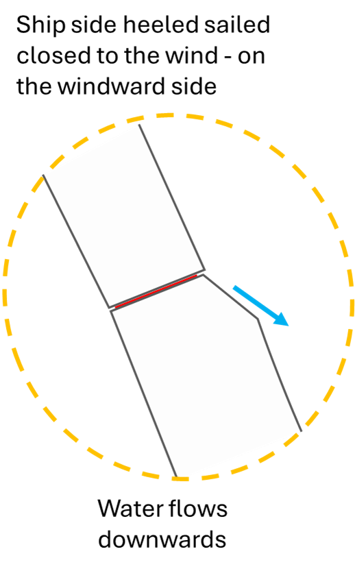
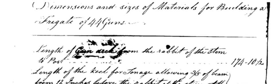
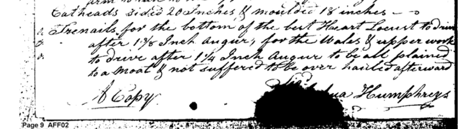
Thanks Gentlemen !! I fully agree being careful with compareing the orginial design with results impacted by later repairs and renovation. Constitution and Victory both have a VERY long history - and since they are wooden ships, most of the timbers have been replaced - often much more than only one time. The good thing in case of Old Ironsides: we have this Humphrey Specifictions written in June 1794 - which at least describe his plan in that year - and which provides the width and thickness of the used timbers. Unfortunatly not position nore final shape (as this dimensions most likely were the "midship" dimensions where planks are widest) and not providing any information about the tapering vs. bow and stern section. And of course also no information about the edge preparation of the designs. ... This seems to be "a copy" which might be the basis for the text in the "American State Papers - naval affairs Vol. I" which often is used as reference. Martin - who collected so many information concering Old Ironsides - unfortunatly is not very precise with his sources - especially in his books. I got a copy of the "a close up" in which carefully lists his sources. His statements on Page 70 ff in "Building a Legend" make from principle perfect sense - but I did not see any source providing that thickness change - nor any details concering the way the thicknes change was done - especially on the main wales. So especially these edges were the concern of our discussion in @The Bitter End´s building log. We were wondering whether the edges are smoothened - to prevent rotten wood at the exposed edges - and "in order to carry the water out of the seam" - a very important issue. Any "unchamfered" edge in the ships planking (where thickness of planks changed) might generate a tiny "plateau". And especially if the ship is sailing close to the wind the steps in the planking on windward side would even generate tiny "pockets" in which the water would be able to stay and work it´s way into the caulking. I used one of Lords section cuts as starting point - just to illustrate the position. If the top edges of the wale would not be chamfered or smothened ... it would look like this, right? And the result on sea would be that one: Water might be trapped and has a lot of time to make it´s way into the caulking or work its way into the wood allowing the planks to start rotting. Chamfered the situation would change: A chamfer done at the wale´s edges must on one side come as close to the next thinner plank as possible - and must be wide enough to avoid any pocket under heeling. It wasn´t a simple 45° chamfer of the edge. It was at least a perfect reshape of the timbers edge to fulfill that task. Even a complete "smoothened" upper wale plank is possible. THIS is the question we try to clearify - do we know from other ships how the edges of the main wales were shaped? I guess if we look into models the builders might not have shown that chamfer - as it is a) hard to produce in a pleasant way (having the chamfer being constant over the lenght) and b) it might be just too small to try to represent it. @Force9 you sure are right concerning John Lord´s reconstruction - which is impacted a lot by his given timeline and budget. But what chance did he have? .. At least his two section cuts from 1926 showing his research seem to me to be not that bad! He tried to follow Humphreys written specs - and he obviously studied paintings (Cornè and others) and "old models" (Hull Modell?) - and he did not have internet ! But I agree: one must be careful in studiing his results. .. and that´s what this posts is about 😄 By the way: Haiko @The Bitter End was pointing on the fact that even in my examples of Hartt Shipyard build ships like USS Enterprize and Boston one might be able to see a tiny edge indicating the wales ... Do you see that tiny bright line below the gun streak? If you look into the engraving you even think to see a line in the midship area .. One would need to see the original engraving to study that effect better ..

-
Wales
Marcus.K. replied to -Dallen's topic in Building, Framing, Planking and plating a ships hull and deck
Let me dig deeper in this topic: @Mark P was stating: Is that really true for all ships? @The Bitter End found in his building log USS Constitution by the Bitter End - Wales reason to doubt that. Were the wales, which consisted of thicker planks than the regular ones, left with sharp edges at their margins – or were the transitions to the thinner planks worked in such a way that no visible edge remained? We found that the Isaac Hull Model does not show the wales at all. Here in this photo - taken by @Force9 - we can see no edge indicating the contours of wales. John Lord - in his reconstruction of Old Ironsides between 1926 and 1931 produced several - at least - 3 drawings with 4 different section cuts, in which he showed different approaches: In his Feb. 1926 drawing #35208 he shows what his research of the Joshua Humphreys papers and other sources seem to have indicated: The 6 thick planks of wales are supported by not as thick (but thicker than the planks) 5 planks "black strakes" on top and 4 planks "thick stuff" below the main wales. The dimensions for sure were provided in Humphreys list of material. Of course - what nobody can know from the written specification of the materials main dimension of Humphreys list : did the shipwights smoothen the edges - or did they keep the edges "sharp" or with a certain chamfer - so that the thick strakes or the main wales would be notable as being something other than the classical planks? In his Jan. 1926 drawing #34535 he represents on left side the ship as he found it - most likely done in the earlier 1906 resoration - while the right side shows what he by then found after "considerable researche" including "old models", "drawings", "paintings" ... The 1906 / 1926 Ship seems to have the edges of thicker planks smoothened - so that at observation no one would notice which of the planks are wales, which are planks. It would look like this photo: this is the 1926 ship - at the beginning of Lord´s restoration process - as he "found" it (like in left side of the drawing #34535). On right side of that drawing it now seems that only the top edge of the wales have a sharp edge. If we look at Lords final drawing #24472 done in June 1931 we can see that now even the top edge of the wales are not visible anymore - just as the ship was done in 1906: O.k. .. all those drawings were done in the late 1920s .. ca. 130 years after the ship was launched. How was it done in those days around 1800 ? Let´s see what Maestro Felice Cornè had to show in 1803 - "Frigate Constitution": is there a fine line below the ochre gun strake in the already black area.. just above air vents of the berth deck? ... Hm... Maybe even a tiny indication of a line in about where the wales lower edge would be?? Or do I just wish to see that ..?? Let´s check the sistership: US Frigate President: Antoine Roux - a in many details precise observer of Mediterian Sea vessels painted several times USS President - in around 1803. No prominent wales visible, right? If we look at this beautiful old bones model of US Frigate Chesapeake - done 200 years ago by prisoners of war - this model is in Internationales Maritimes Museum Hamburg. The model builders were experts, sailors knowing those ships in detail. It might have been done by sailors of the USS Chesapeake after being captured in 1813. Would they be mistaken when showing the wales having very sharp edges? You can see on top and on bottom the sharp thickness increase for the wales. Also from british admirality models of that times we also know that often the wales were prominent and clearly distiguisable from classical planks. .. On the other hand: those edges would always be endangered to be damaged, if the ship was struck by harder objects in the water like boats, loads, flotsam, etc.. And those damaged areas would be the starting point of rotten timber .. making repairs essential. So there are pro´s and con´s for prominent wales. It might be that the wales just in models were prominent as they were a very important feature for the admirality or experts to really see the ships "anti-hoggin-stiffneners".. it might be that the wales were prominent in real ships too Maybe some shipwrights just did not smoothen the edges of the thicker wales as this is effort which was not payed - seemed not needed by some? Maybe other ship yards did smoothen the edges as the lower edge would cause resitance and friction in the water and both - lower and upper edge would be senstive for damage. By smoothening they durablity of the planking would be improved - an expensive work - but providing more robustness. maybe just some artists (modelist, paintes, engravers) just did not show this feature? Is it possible that both options existed in parallel? Some ships had prominent edges?.. some had smoothened wales? Maybe it depends not only on the nation but the shipyard what was the preferred design?? So we started trying to find if George Claghorn or the Hartt Shipyard had their own "habit". George Claghorn, the assigned shipbuilder for USS Constitution, was chosen as he was building "big" ships before. We found that a waler - Rebecca - a ship of 175 tons and the first waler to pass Cape Horn and a merchant ship named Barclay with 200 tons have been build by Claghorn before USS Constitution. Non after the big frigate. Unfortunatly no visual description of both ships seem to exist today. A dead end for now. For the Hartt Shipyard there is a bit of visual evidence: This is USS Michigan (https://en.wikipedia.org/wiki/USS_Michigan_(1843)) build some years after Constitution. Its hard to really see - but at least we can not identify the wales .. very little evidence for anything, I agree ! .. a poor picture ... There are two engravings by the french artist Baugean - who was a precise documenter of ships in this age - showing ships build in Hartt´s shipyard: USS Enterprize .. a very smooth ships hull, right? But I agree: here too the simplification by the artist or even the poor representation of the digital photo might just not show the wales. What about this one? Source: https://en.wikipedia.org/wiki/USS_Boston_(1799)# USS Boston 1799 - also build in Hartts shipyard in Boston. Here the artist / the representation even shows vertical lines to show the shape of the hull - and no step is visible at all. And finally even a photo again! Source: https://en.wikipedia.org/wiki/USS_Independence_(1814)# This is USS Independance as a hulk in the 1890s - and if you investigate the area close to the bow - in between that vertical toilet effluent pipe and the start of that 2nd layer of "overplanking" of the ships sides you recognize the orginal planks of the original hull of the ship - and again: no step is visible, no sharp edge. And of course: the photo is not very sharp - and we don´t know whether the planking is still the original one. The ship had been razeed years ago - and for sure had to go through repairs .. who knows how old those planks are. Summarized: do those few examples provide real evidence that at Hartt´s shipyard it was custom to smoothen the wales? .. a "thin ice" assertion - maybe, maybe not - but a possibility. If we add the Cornè-painting of 1803 .. and if we assume that this tiny line SHOWs an edge, ... well .. all that is interesting - but does not really solve the mystery, right? Now to you, shipmates, comrads, experts, sirs, ladies and captains .. Does anyone of you have better evidence of what was done in about 1800 in Boston´s Shipyard - or in the US in general - or .. in other nations? Is there any known logic? Were edges always prominent? Was that sometimes the case - and sometimes not? .. if so, why and where? Did any authority in age-of-sail describe this feature in detail?