HOLIDAY DONATION DRIVE - SUPPORT MSW - DO YOUR PART TO KEEP THIS GREAT FORUM GOING! (Only 13 donations so far - C'mon guys!)
×
Marcus.K.
-
Posts
351 -
Joined
-
Last visited
Content Type
Profiles
Forums
Gallery
Events
Everything posted by Marcus.K.
-
 Ah - that´s interesting !! Sure!! I did not realize this salute process! THANKS @Chapman
 -
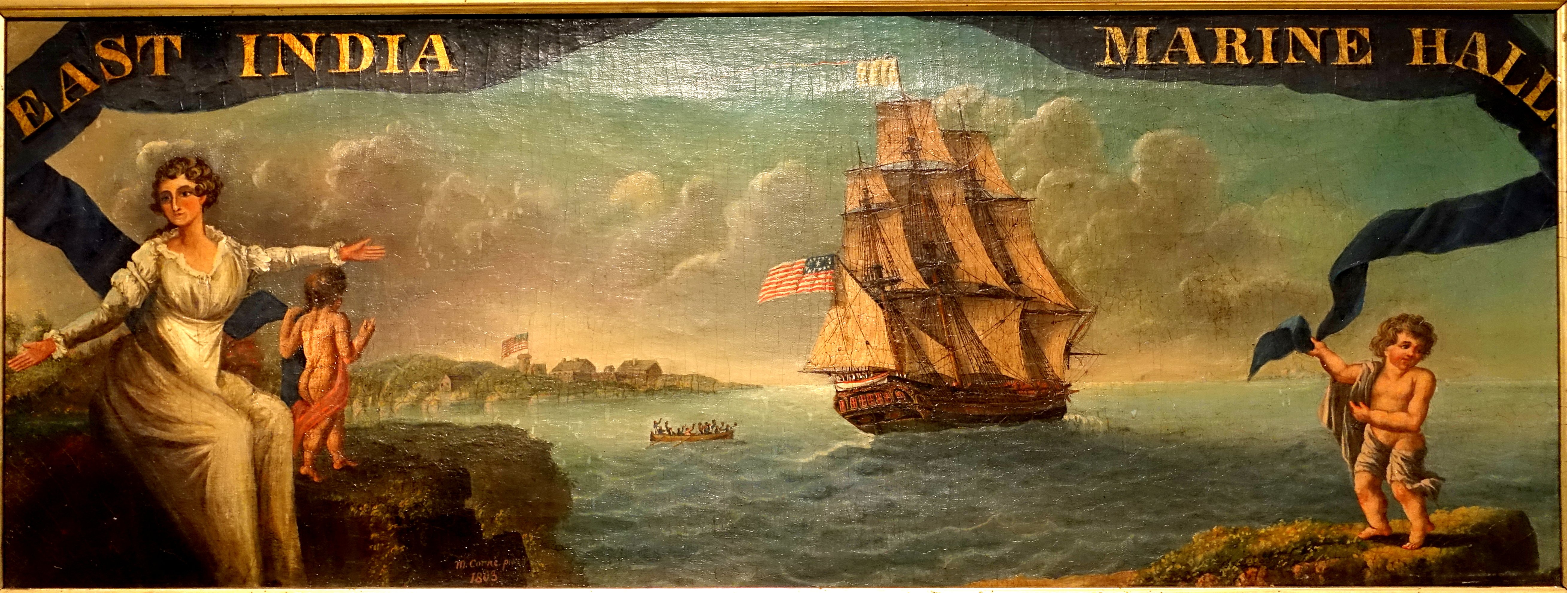
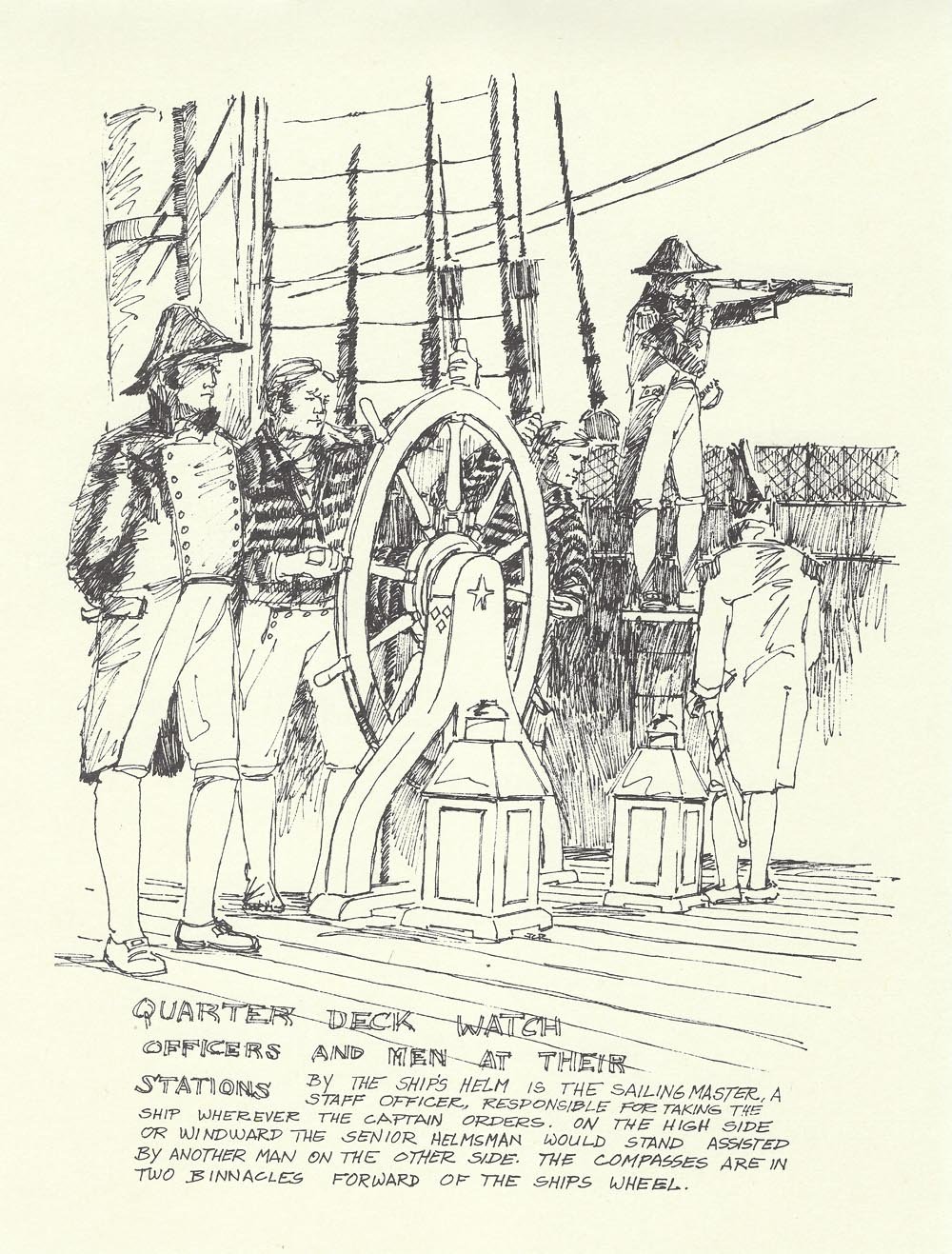
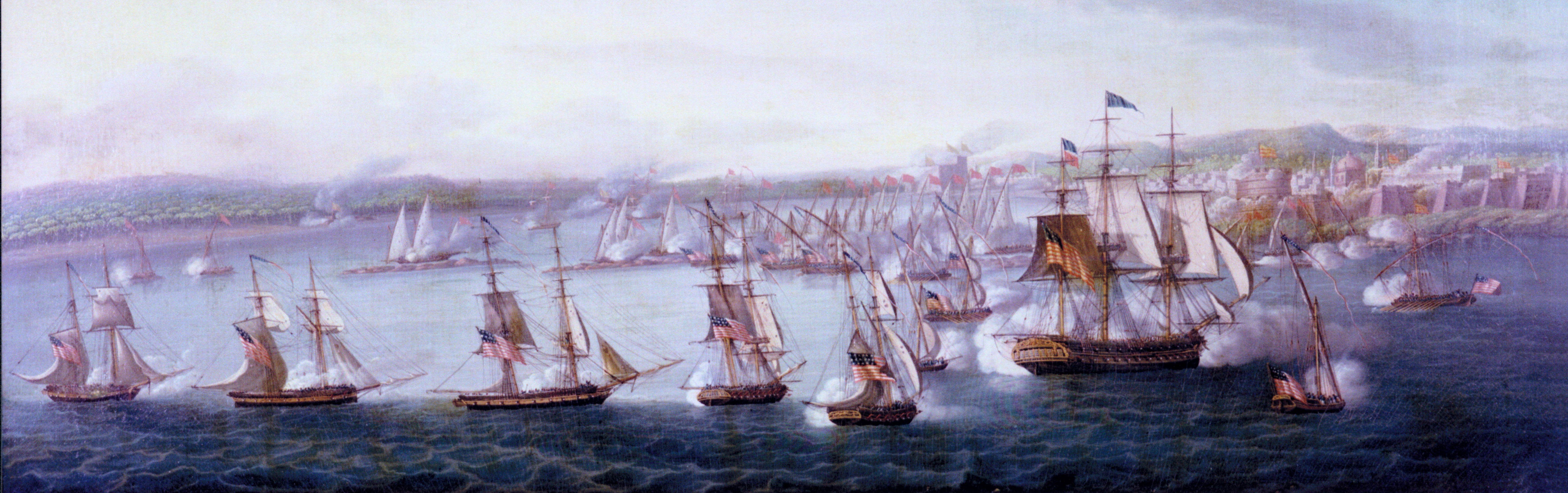
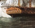
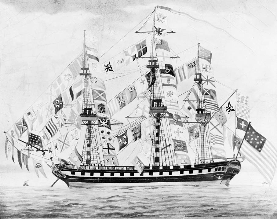
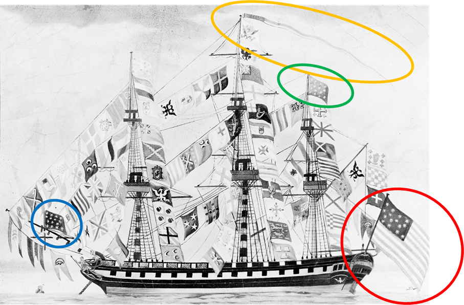
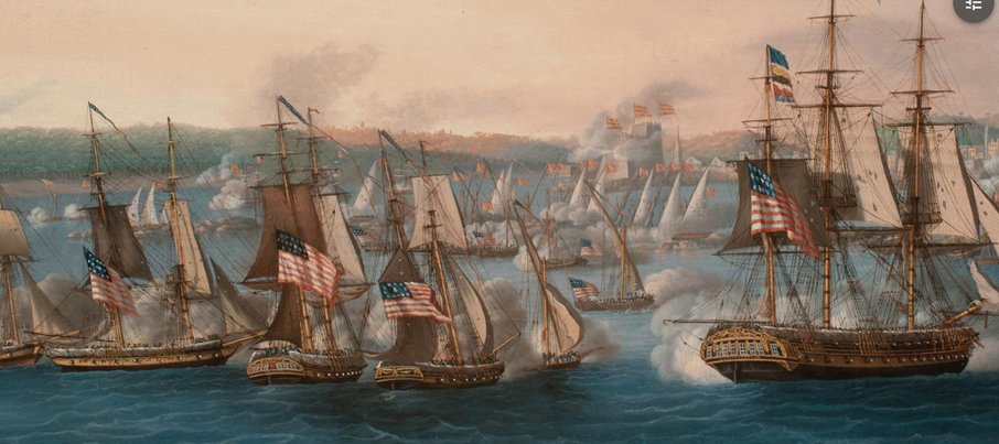
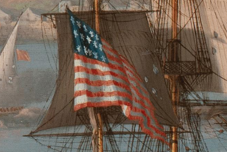
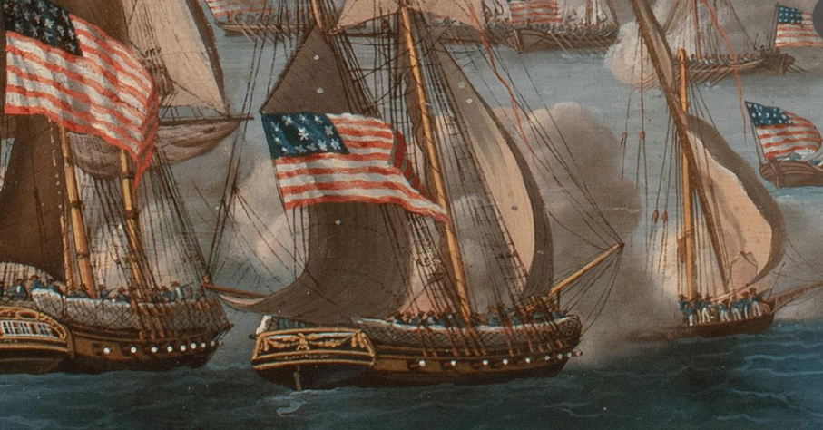
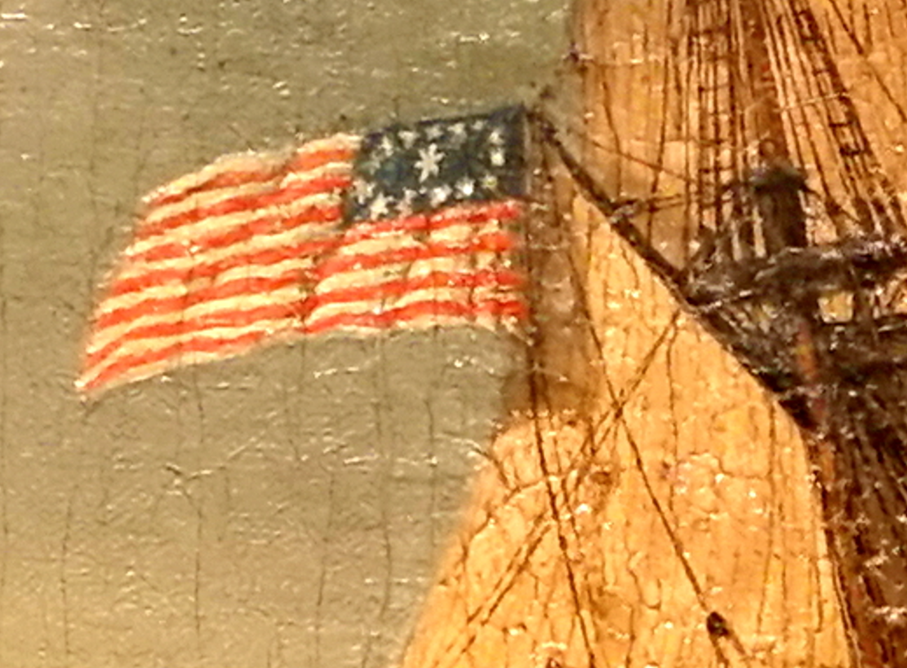
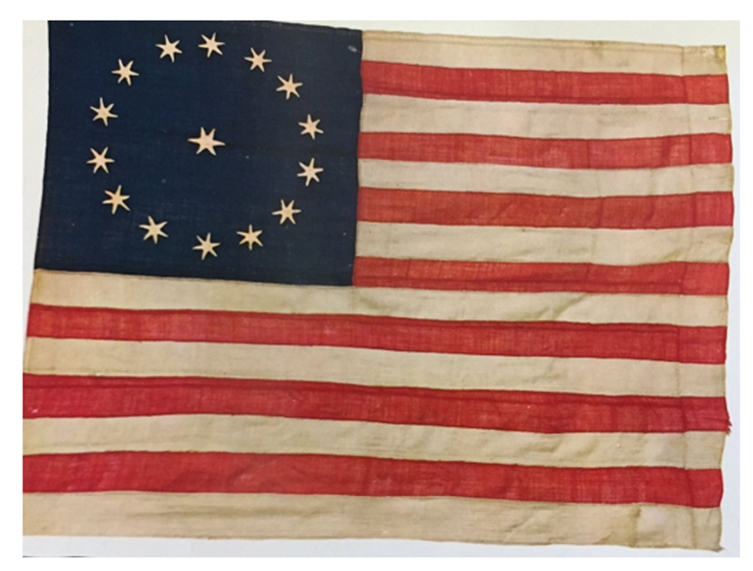
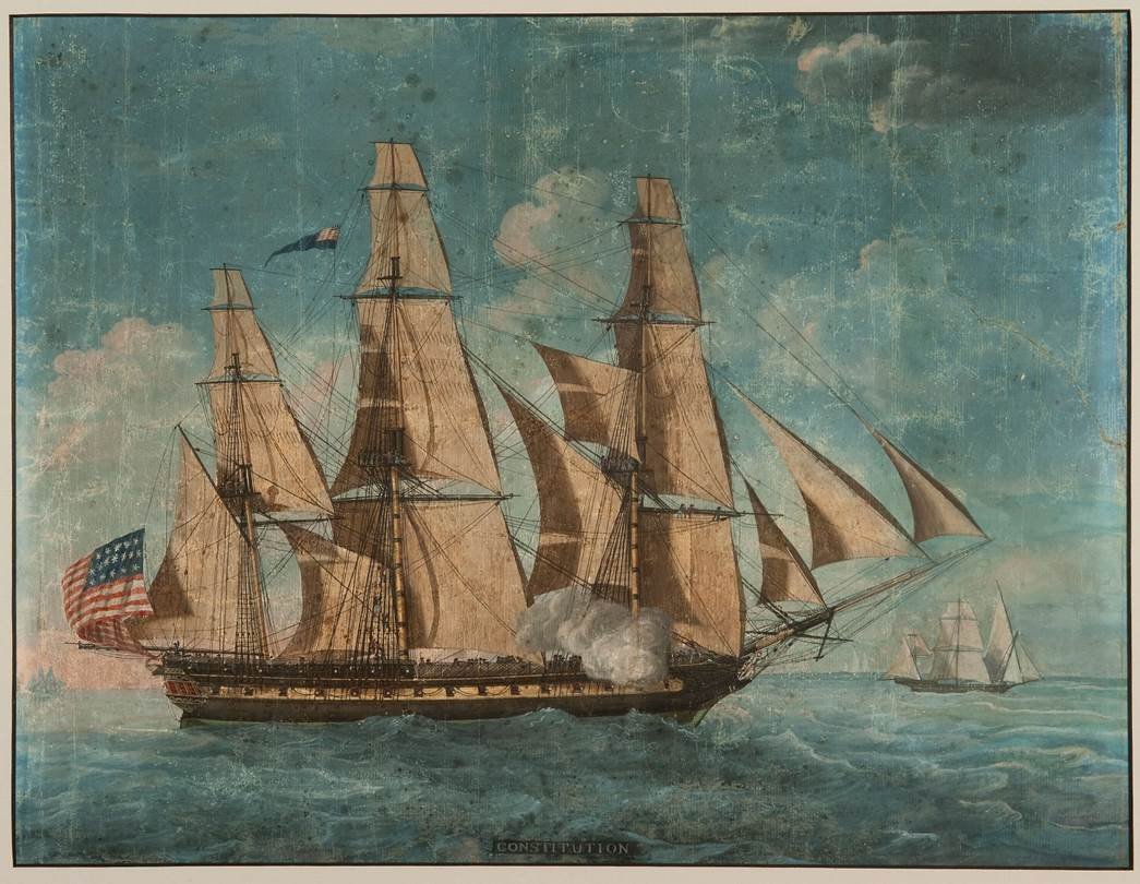
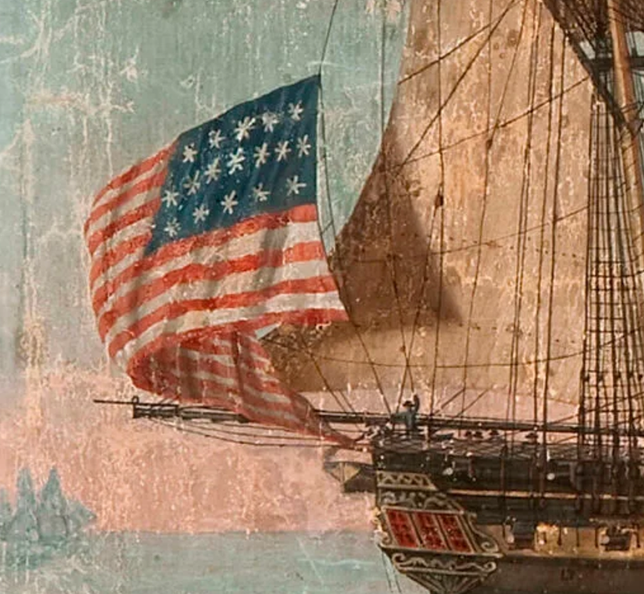
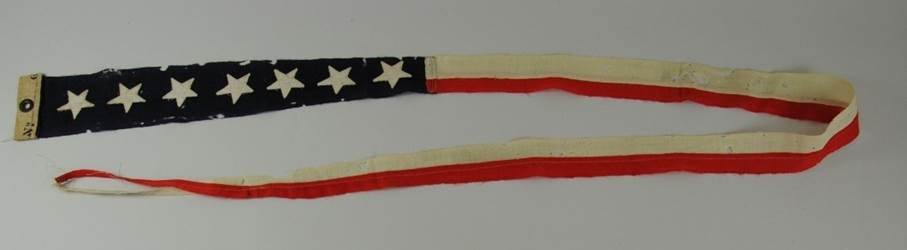
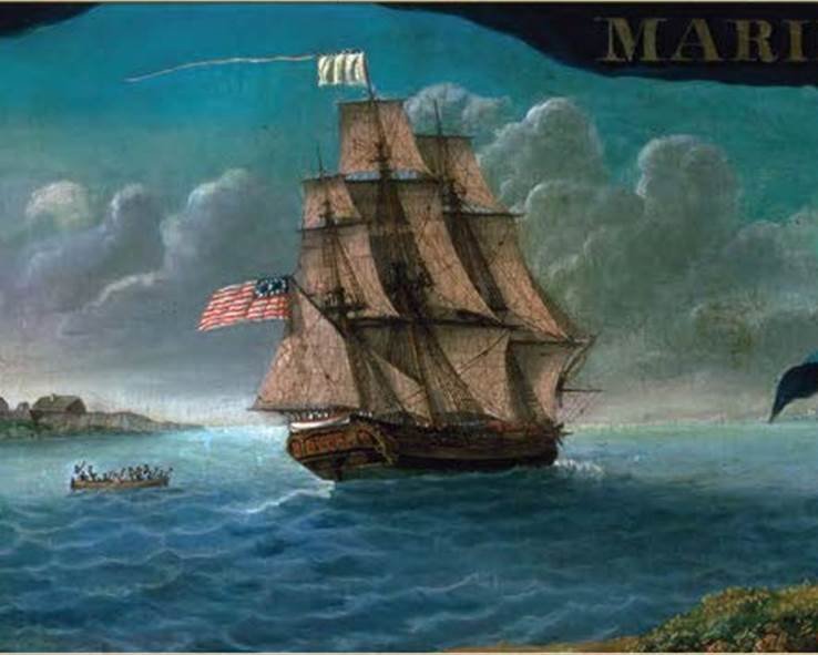
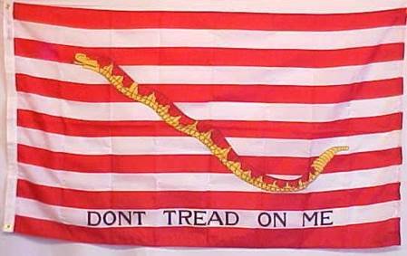
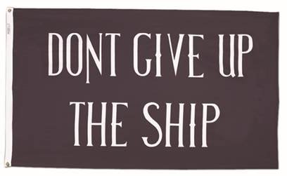
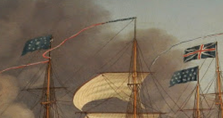
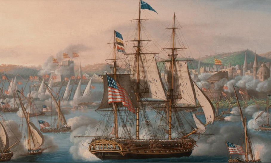
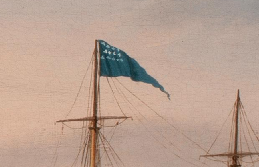
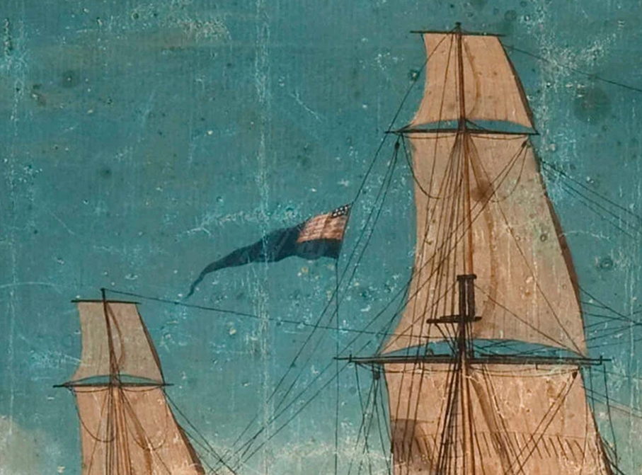
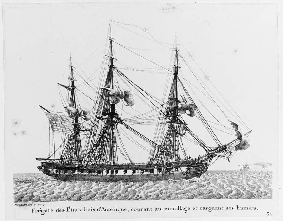
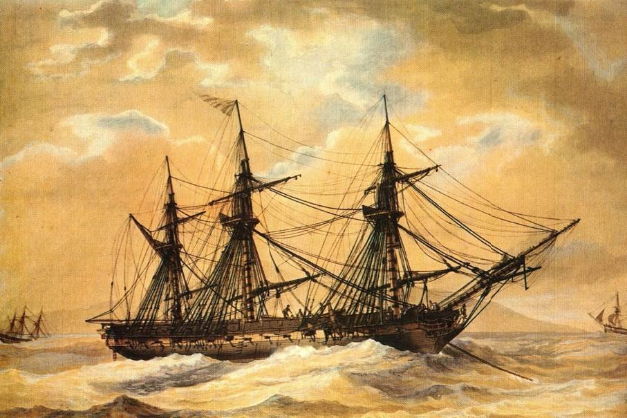
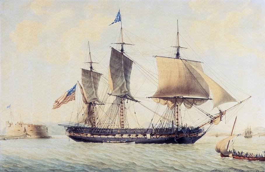
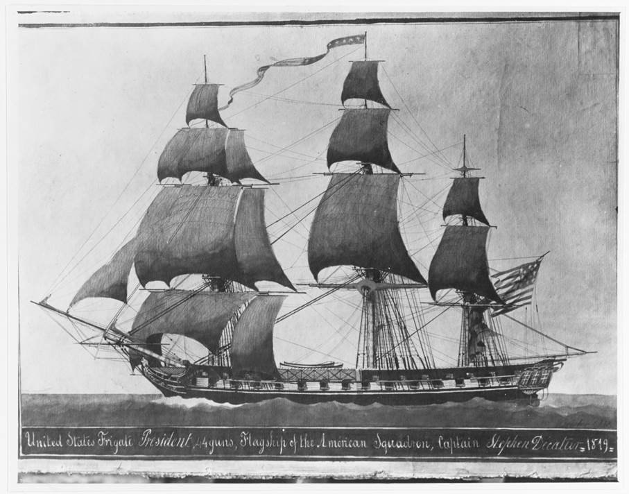
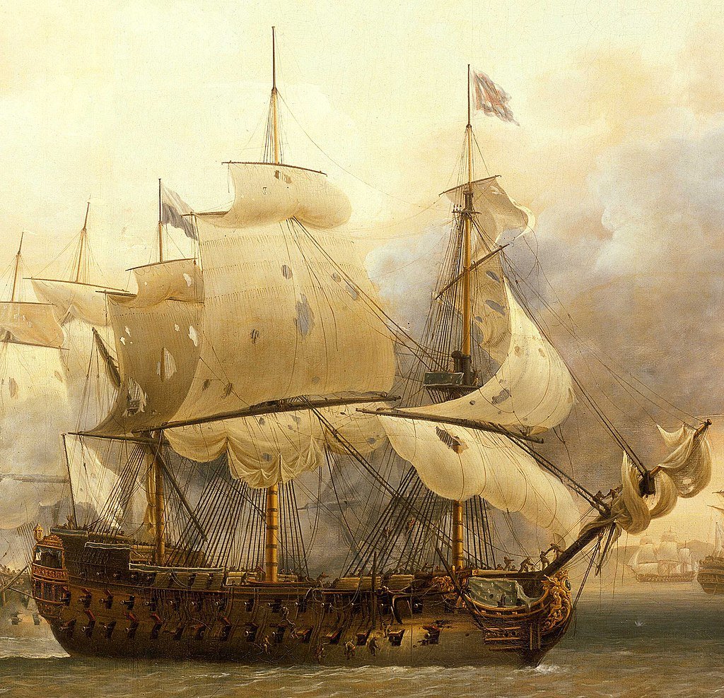
1. Overview In the early years of the U.S. Navy, there were no formally codified regulations for identifying naval vessels. The processes and traditions of the fledgling service were still in the making. Standardization was not yet the primary concern—rather, the focus lay on establishing procedures and organizational structures. Undoubtedly, there existed unwritten customs rooted in British naval practice and those of other maritime nations, though concrete documentation is scarce. Nevertheless, some sense of what was common practice can be gleaned from period illustrations—particularly the many works of American maritime painter Felice Cornè, among others—as well as from occasional primary sources, such as a 1803 inventory recorded by Midshipman Henry Wadsworth aboard the U.S. frigate New York (Langley, 2003–2004). Wadsworth records the following items: · 4 american Ensigns · 4 commission pennants and 1 Jack · 2 american Burgees · 3 american Broad Pendants The Ensign was the national flag, typically flown from the flagstaff at the stern. In battle, it was often hoisted on additional masts or spars to ensure it always remained visible — since lowering the flag during combat was interpreted as a sign of surrender. To avoid any such misunderstanding in the event the main flagstaff was shot away, it was both common and critically important to display at least one additional, redundant flag. The Jack was a smaller flag used to indicate a ship’s nationality. It was flown at the bow—typically from a short staff mounted on the bowsprit or foredeck, known as the ‘jackstaff’—but only while the ship was at anchor or moored.. Commission Pennants (historically also spelled 'pendants') are long, narrow, triangular flags that were to be flown from the highest mast of every officially commissioned warship. Their purpose was to distinguish naval vessels from merchant shipping. American Burgees were smaller flags bearing national symbols—such as the ‘Don’t Tread on Me’ flag or various designs featuring stars and/or stripes. In modern usage, burgees are typically triangular pennants, most commonly recognized in the sailing world as flags denoting membership in a yacht club. Broad Pennants — also referred to as command pennants — were used to indicate the rank of a squadron commander aboard a particular vessel. Importantly, when a squadron leader or higher authority was present on board, the broad pennant would replace the long, narrow commissioning pennant at the masthead. 2. The Ensign In its early years, the American national flag was not yet standardized as it is today. Since the United States was still in a formative and expansionist phase, and new territories continued to join the Union, both the number and the arrangement of stars and stripes on the flag varied over time. What remained consistent, however, was the general layout: a blue canton (the upper hoist-side quarter) bearing white stars, and horizontal red and white stripes—varying in number—filling the remaining three quarters of the flag. In those early years, as is still the case today, each state was represented by a star in the canton. However, at the time, each state was also symbolized by a stripe—distributed across the rest of the flag. Only in 1818 was the number of stripes officially limited to thirteen, in honor of the original thirteen founding states, as it had become increasingly difficult to distinguish the red and white colors clearly when the number of stripes exceeded fifteen. Above section illustrates that, at least in 1804/05, ships in active service could still be seen flying different versions of the national ensign side by side. With the admission of Vermont and Kentucky, the flag at that time displayed 15 stars and 15 stripes. In the following section, we will take a closer look at these flags: In this view the U.S. frigate Constitution displays the classic '15-state flag' variant, with the 15 stars arranged in three rows of five. To the left of USF Constitution the U.S. schooner Enterprise is shown flying a different variant, the so-called 'Maryland pattern,' which typically featured white border stripes and 14 stars arranged in a circle with one central star. However, it seems that Felice Cornè simplified the design somewhat, as we can only count 12 stars and 14 stripes. While the missing stars might be explained by a possible fold in the flag, the complete absence of the lower white stripe appears rather peculiar. That Cornè was capable of greater precision becomes evident in the following illustration, which is in fact even older. Here in above picture, we can clearly see all 15 stars and 15 stripes—just as they appear on the original shown in the next photo. However, even at this stage, it becomes apparent that having 15 stripes makes it increasingly difficult to distinguish them individually from a distance, and the red and white begin to blur into a washed-out pink hue. This photo shows an original national flag in the Maryland pattern: 14 stars arranged in a circle around a central 15th star—and 15 red and white stripes, with a white stripe at both the top and bottom. Felice Cornè’s well-known side view of the U.S. frigate Constitution from 1803, the earliest known depiction of the ship, shows a version with apparently 17 stars. This may indicate Ohio and Tennessee, which had already joined the Union at that time but were not yet officially represented on the flag. The number of stripes is somewhat puzzling again—there are only 16—and the top stripe is white while the bottom one is red. Cornè’s effort to depict such a large number of stars can certainly be seen as an attempt at accuracy. Had he been merely imprecise, the more logical outcome would have been to show fewer stars rather than striving to cram more stars into such a small space! It was not until 1818 that it was legally mandated: one star per state, and 13 stripes representing the founding states. This rule remains in effect to this day. However, this also shows that flags in the early years of the new nation still allowed for certain liberties—a topic that alone could easily fill an entire book. 3. The Commissioning Pennant British, American (and likely other nations’) warships flew a long, narrow, triangular pennant at their main mast—the so-called commissioning pennant—as a symbol of their active (military) service status. The American version displayed at the hoist a blue field with vertical red and white stripes. Today it bears seven stars - in earlier times, thirteen, symbolizing the founding states. The origin of this flag and tradition can be traced back to ancient Egypt and has been in continuous use through the Middle Ages to the present day. The commissioning pennant was only replaced by the flag of an admiral or high-ranking civilian official when such a person was aboard. However, it was both possible and customary to fly another flag beneath the commissioning pennant—for example, as a salute or for signaling purposes. This image possibly depicts the early Old Ironsides. However, Cornè may have intended it merely as a ‘typical’ frigate, since the entire painting centers on the theme of the East India Marine Hall, and the frigate serves only as the central focal point. What can be observed, however, is that beneath the long commissioning pennant another rectangular flag is flown. Could this be a salute to the honorable East India Marine Society? 4. The Jack The so-called 'Jack' is also a national flag, displayed only when the ship is at anchor or moored, flown on a short staff at the bow. This allowed for identification of the ship’s nationality when approached from the bow. Such identification was often necessary when the ship was at anchor and the stern had turned into the wind, rendering the ensign at the stern invisible. Typically, the Jack is a simplified version of the national flag, displaying only the ‘canton’ — that is, the upper left field of the U.S. national flag: a blue field adorned with the appropriate number of stars. The so-called "First Navy Jack" featured the rattlesnake and stripes motif, inspired by the 1775 Continental Army flag—a symbol of resistance and independence from the British Crown. However, this flag was only officially used between 1975 and 1976 (in preparation for the Bicentennial celebrations) and again from 2002 to 2019. There is no evidence that it was flown during the early years of the still young U.S. Navy. 5. American Burgees There is little information available today about the "American Burgees." Burgees—typically smaller, triangular flags—have historically served and continue to serve as identifiers and communication signals between vessels. In addition to the ensign, these “American burgees” were evidently intended to mark a ship as distinctly American. Flags bearing inscriptions such as “Don’t give up the ship” might also be understood as burgees—a powerful symbol directed at both friend and foe. Captain Perry referenced the last words of his friend, Captain James Lawrence, during Lawrence’s engagement aboard the USS Chesapeake against HMS Shannon in late May 1813, and successfully used the motto to rally his own squadron during the Battle of Lake Erie in late summer 1813. This representation again depicts national flags on the foremast and mizzenmast of the USS Constitution, as Cornè portrayed them in one of his paintings of the battle against HMS Guerriere. Once more, it is evident that the arrangement of stars in the blue field had not yet been standardized, and different patterns could even be flown simultaneously on the same ship. 6. The Broad Pennant Up until shortly before the Civil War, "Captain" was the highest permanent rank in the U.S. Navy. Captains commanding a squadron were honorarily titled "Commodore" and flew a broad pennant. These pennants came in blue, red, or white depending on seniority and displayed stars representing each state: · Blue with white stars for the senior-most commodore · Red with white stars for the second-ranking commodore · White with blue stars for all others Therefore, Wadsworth likely recorded “3 broad pennants” in his midshipman’s logbook. The large U.S. frigates such as the Constitution, United States, and President were the biggest ships in the Navy until the War of 1812 and often served as squadron flagships. With the arrival of a senior (in service) commodore aboard his flagship, it was clearly necessary to adjust one’s own squadron rank by changing the color of the broad pennant. Hence, all three colors were surely needed on board. . Commodore Preble, for example, flew a blue broad pennant with 13 stars—symbolizing the founding states—during his operations off Tripoli in 1804. The shape of this pennant was a wide, truncated triangle. It was only years later that the now-standard swallowtail design became common. Signal flags are also displayed on the mizzenmast in above´s picture. In Cornè’s 1803 depiction, a broad pennant is being hoisted that appears to show the American ensign instead of stars. This again indicates that flag usage in the early U.S. Navy was not yet strictly standardized. 7. Other depictions done by other artists The rigging and flag display of American frigates can, of course, also be observed in other paintings. The already mentioned exquisite French artists lead the way, of course! But other depictions naturally also show the common practices already in use. In the storm, only the broad pennant remains hoisted on the main mast. All other flags were likely taken down for safety. This is a magnificent painting by Antoine Roux that reveals an incredible number of details about the large American frigates. Studying this work — as well as the painting of the President in the harbor of Toulon — comes highly recommended for anyone interested in the American 44-gun frigates. Here, we again see the commissioning pennant and the national ensign at the stern. The jack is not yet hoisted, indicating the ship is not at anchor. A very fine example of the long commissioning pennant, still showing clearly more than the seven stars commonly seen today at its hoist. 8. Conclusion It is important to keep in mind that, in addition to the lack of standardization of flags at the time, there were also inaccuracies in the artists’ depictions. However—despite all criticism regarding precision and the contradictions found, for example, in Cornè’s works—a closer examination reveals remarkable accuracy and attention to detail. Even the apparent contradictions can be explained, and the accusations of “errors” or “simplifications” often seem exaggerated when considering how many intricate details he managed to depict in the tiniest areas of his paintings. Compared to his French contemporaries like Roux or Baugean, Cornè may have lacked a bit of precision. Yet he was capable of rendering minute details and indeed did so. Therefore, when he chose to depict small details deviating from today’s expected “norms,” such as adding a miniature national flag to the broad pennant instead of the often used 13 white stars only, it is unlikely that this was done on a whim. Rather, it can be attributed to the still undefined rules concerning the exact design of official flags. Based on the many beautiful illustrations and some scarce written records, the early national and command flags and their usage can be fairly well reconstructed. As with any historical research, one must carefully study the customs and practices of the era to achieve a more realistic representation of the original. The lack of standardization complicates this somewhat—but nevertheless, certain rules can be identified that allow for an accurate depiction of an early US frigate.

-
Hey @uss frolick .. you nearly got me 😜 ... That flag seemed really to indicate: "not a warship".. but.. Tonnerre de Brest!!! The photo of that painting was done not very well - as the flags are partly covered by reflections of the flashlight. If you see another representation of that scene - on the book cover of George H. Schwartz´s interesting book, you´ll notice a pennant on top. I guess this indicates: Navy ship in duty - maybe "greeting" the Society with that 2nd flag? See here: A men-o-war ? .. with guns stored inside? I believe to remember having read in Tyrone Martins "a most fortunate ship" that during the early travels of Old Ironsides the guns were stored completly inside - which caused a lot of issues concerning the available space on the gun deck - although the guns were a bit shorter than needed for the battle. Later then the configuration was changed and the gun ports (still not hinged but removeable) got this split which allowed the guns to be stored "outside" while having the ports closed and sealed. That - and the dark shadow Cornè chosed to set the side into - would explain the lack of guns at the ships side. A thesis .. What do you think, Ladies, Gentlemen? also very interesting is that design of the US Flag at the stern. I know there were many different ones during the times - depending on how much states joined the union - and of course the early "finding phase".. but I never saw anyhting like that?


- 233 replies
-
- 1
-

-
- Model Shipways
- constitution
- (and 5 more)
-
This is the first time I see that last photo - with the stern at the hull - and it´s just incredible !! What a beautiful sight ! I said it before and I have to repeat it here: this cross-hemispherical cooperation is a lot of fun and how you, T.B.E. realized for what I before just had a rough idea was and still is a miracle. I have to state that T.B.E. really had to shorten that explanation about how we found the presented layout. As he mentioned - it was journey for several weeks with a lot of exchange of information, concerns, rethinking, again studiing the sources, even finding new ones (!), rethinking the old interpretation .. Just as an example: T.B.E. did not like the appearance of the white window frames - and while discussing the possible alternatives and their likelyhood we recognized that the 1803 Cornè painting - done before the 1804 Tripolis-paintings showing that stern! - showed red window frames in the galleries. Accidently we stepped over another representation of the ship which - it seems - by now has not been identfied as USS Constitution. And even if it is not Constitution - the similarities are really obvious ! - it at least shows that red windows on a big American frigate are a likely alternative: This is a painting in Peabody Essex Museum in Salem, MA, USA. It was done by Felice Cornè in 1803 - the year he did that famous side view. Even if the ship was just intended as a "typical" American frigate - it shows red window frames we believe the ship had in its earlier years. From historian point of view it is not a proof - as both sources are Cornè and one of the sources even does not for sure represent Old Ironsides. But we think in a case like this, where not that much sourves are available the principle of Occam´s Razor must be valid. Or if you take the name "Constitution" on the ships stern: Cornè showed it like this: and in his 1803 side view - he presented the name like that below the ship: William Bass (Author of "Old Ironsides - Superfrigates of the many faces") calls this font "roman" .. And what T.B.E. did by hand to represent this on the model is justs incredible! I will as soon as possible try to recollect and write down that interesting journey and our findings in @uss frolick "stern view" -thread - as we did not only reconstruct the 1797 stern in more details - but also found out more about the 1812 stern worth sharing. What impressed both of us a lot: when we were "theoretically" considering the likelyhood of this or that detail - found a desicion based on pure ration ... and T.B.E. realized it on the model : it always added an even better balance and beauty to the structure. .. as if that new feature really belonged to that position! As if the beauty itself wanted to be a proof. This focus on "function", "likelyhood" and "ratio" leads to a very credible and plausible design - which also has the beauty of a baroque stern. That was a unique experience! Thanks a lot, T.B.E.. Looking forward to our next steps!


- 233 replies
-
- 3
-

-
-
- Model Shipways
- constitution
- (and 5 more)
-
TBE found an interesting entry in "History of the Liverpool privateers and letters of marque with an account of the Liverpool slave trade" which was minutes ago available in Internet-Archive .. by a Gomer Williams printed 1897 .. in which a "Captain William Hutchinson, an experienced privateer commander, originally trained in that finest of all nurseries for seamen, the Newcastle colliers, who afterwards became dockmaster at Liverpool" explains how he prepared is privateer for battle: Page 11: and Page 12 to 13: So much to bravery and "gentlemen's attitude" in battle 🙂 .. but hey, we talk about the common man, the sailor, the marine .. And here now the important sentences - proving that hammocks were - at least sometimes - used "in the tops" .. meaning in the fighting tops. That seems to be visible in THIS beautiful painting of the French Ship "Saint-Esprit" .. we see the horizontal hammocks along the shrouds - and we see at least a blue canvas (with white or golden lilies) in the fighting tops side - above the foremasts top shrouds - hammocks possibly stacked behind it. https://en.wikipedia.org/wiki/French_ship_Saint-Esprit#/media/File:Vaisseau_français_le_Saint-Esprit_au_combat_en_1782.jpg Thanks @The Bitter End Haiko, for this finding! There we have at least a verbal prove that hammocks were used in the tops to protect the sailors, marines and sharpshooters from the enemies sharpshooters.
-
Interesting project - and you said already: "some artistic license" .. Nevertheless: I would close that lowest gun port - as t would be below the water line. There are other issues in your design. But the question is of course: what´s your goal? Your title still leave a lot of room for interpretation of how deep in realism you want to end up? That ship shown here is interesting. A 3-decker for sure. What I noticed: iron stiffeners at the knees and there seem to be strengthening frames on top of the inner planking in the hull. I don´t know enough about the 3-deckers.. but I guess the shape of the hull is not a French design (at least in smaller units they had a less "round" profile). A very flat bottom... Hm.. Could it be HMS Victory? Would of course be the most likely one, right? Worlds most famous 3-decker ...
-
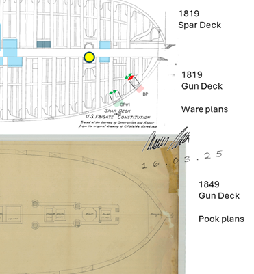
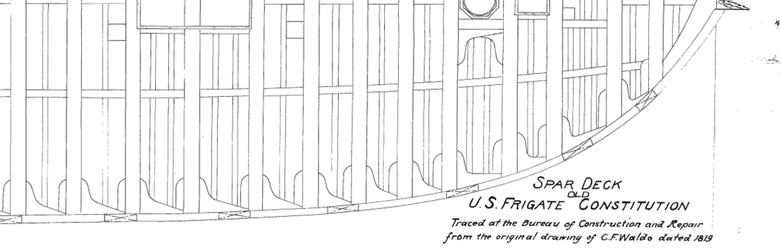
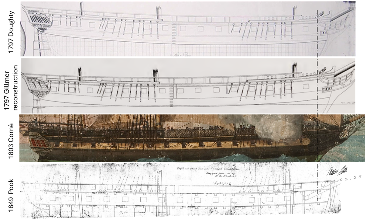
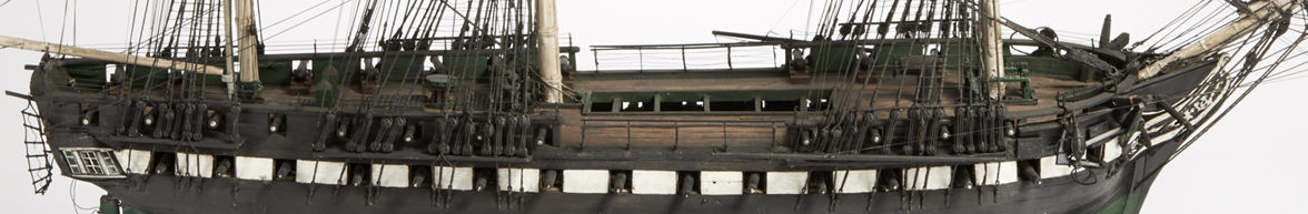
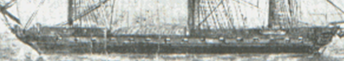
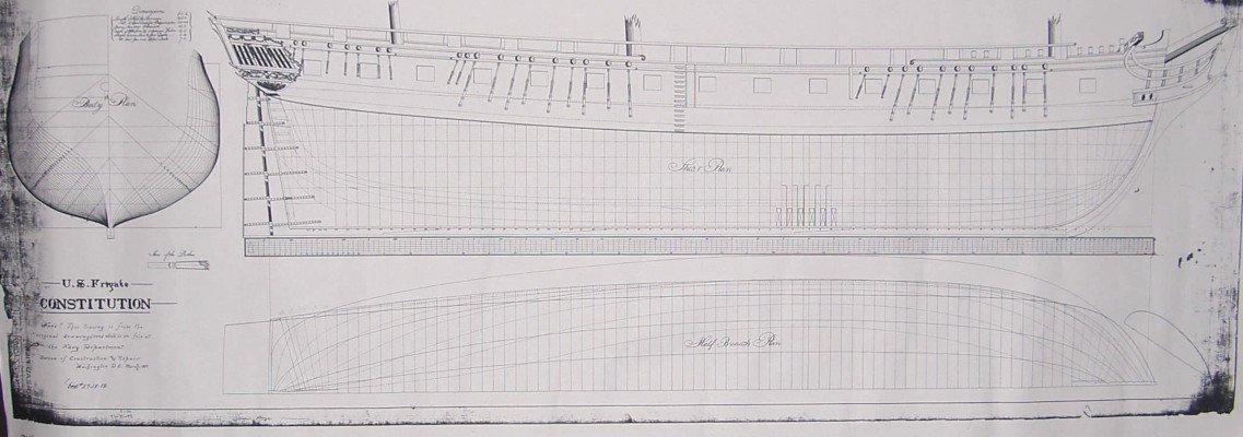
I was trying to find photos of Antczak´s beautiful model. I remember we talked about it in our PN conversation - and I remember to have seen more photos than the ones I find right now. He did an exceptionel beautiful model, with a lot of very good, very interesting and very likely features for the 1797 concept (as I believe it was - of course nobody knows for sure 🙂 ).. But we noticed then and here again some strange features, which most likely were not existing or differing. The port with the red shutters is the "16th port" below the cat head - which must be that "bridle port" I referred to in one of my previous post. THIS - most likely - wasn´t existing until about 1812, when Bainbridge prepared the third 1812-15 war cruise - just after Hull came back from his defeat of HMS Guerriere. I am searching my documents - but I don´t find the sources for this statement! 😕 Someone able to help me on that? The bridle Port - when added - was smaller than the gun ports following (as there is another later mentioning in one of the logs that the bridle ports were cut to the size of the gun ports - indicating that they were smaller before) - and I don´t find THAT sources either! Need to read my Martin´s "Close up"!! It for sure would have had a lid to be closed - as it was the one most affected by wafes from the bow. .. but I do not believe that it was existing in the early years. If you compare with the Doughty Plan, you will find the very first gun port is just one before the fore mast channels. Below the cat head: no opening in the layout - and most likely not in the later existing ship. I compared the 1819 Ware Deck Plan with the 1849 Pook Gun Deck Plan and you can see the Bridle Port (red marked) in 1819 - being a tiny little bit smaller than the Gun Port #1 (green marked) - while in 1849 the bridle port hat the same size. You also can imagine that any gun there would not have room to run inwards - considering the bow sprit sitting in the center of the deck. No "chase gun" on gun deck level. Here you have a bigger shot of the 1819 Ware Plan - and you see the position and size of the Bridle Port .. In a comparision of Doughty´s plan, Gillmers reconstruction of the 1797 status, Cornè´s 1803 paiting and Pook´s 1849 side view, we can see: in 1803 there seemed to be no Bridle port - although I admit: Cornè´s bow area is a bit awkward .. he seemed to have issues with perspective and dimensions here.. So it is not a proof - but a certain evidence I would give to Cornè. My conclusion: I would rather NOT show an opening below the cat head. In my opinion (until I change it 😁) the first Gun port is the one just forward the fore mast channel.
- 233 replies
-
- 1
-
-
- Model Shipways
- constitution
- (and 5 more)
-
For landlubbers and newbies in Constitutions early configuration: Be aware that the configuration on spar deck changed between the beginning in 1797 to maybe about 1809/10 for which we have a sketch presumably by Rogders - showing still the orginal and equally between the gun deck ports distributed 7 gun ports in the quarter deck ... Don´t be confused by that boat hanging in the david .. but I think one can see that the quarderdeck gun ports still are in between the gun deck gun ports, right? ... while the later in 1812 the Isaac Hull model already shows the 8 wider carronade spar deck gun ports which are - naturally - not perfectly fitting in between the gun ports. Photo courtesy by Peabody Essex Museum, Salem, MA, USA We know that the ship recieved in 1810(?)/11 the 16 new 32-pounder carronades.. It is very likely that the quarderdeck bulwarks were modified by then .. or maybe later in 1811 in Washington´s Navy Yard, when Isaac Hull took over the command and organized the refit. But that´s not very likely as the ship would have had no spar deck battery while traveling from Boston to Washington without the modification of the too small and too few gun ports. Possible - but not very likely. So just in case someone wonders .. the early configuration differed a bit. And what we see today is still the 8 wider "Carronade" gunports per side along the quarterdeck. Haiko, you sure know that the ship also did not yet have the "16th" "gun port" in the bow - which in fact is a bridle port - not for guns and which - when it was cut by Bainbridge into the hull in - was it end of 1812? - were even a bit smaller than the 15 gun ports on gun deck level. .. just in case 🙂 Interesting maybe: it seems the ship in Rodgers sketch seem to show upper gun lids on gun deck level. Which pretty sure wasn´t the case in 1797 and at least until 1804/05 when Cornè did his beautiful paintings. In those days the ship had detachable gun port lids. But maybe the sketch shows detachable - but mounted and opened - gun port lids. .. We assume them to be detachable at least until 1812 - as the 1812 Hull model again is shown in "battle configuration" without the detachable gun port lids (except the 2 most forward ports - where waves might be an issue even in good weather). Even in 1817 Ware Side view - no fixed gun ports yet ...
-
I changed my mind: after checking on the Isaac Hull model of 1812 - in which the deck components were done in this special green already - the carriages seem still to be in red. A very dark, dull and faint red (maybe due to the age of that color).. but clearly a red. Still .. its all just guessing.. right? I was checking on other forums - the only discussion about red I found here - click me
- 233 replies
-
- 1
-
-
- Model Shipways
- constitution
- (and 5 more)
-
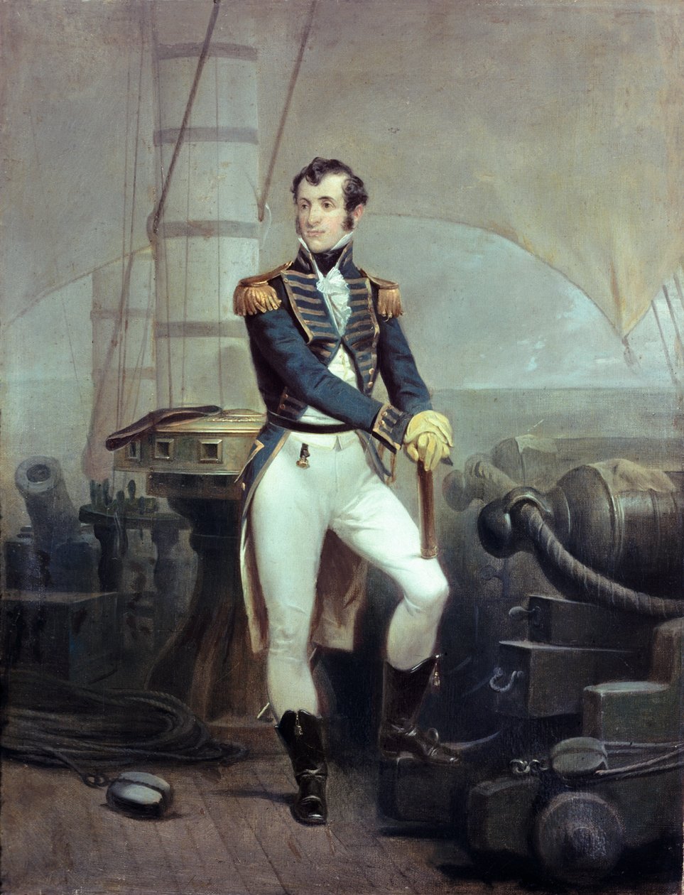
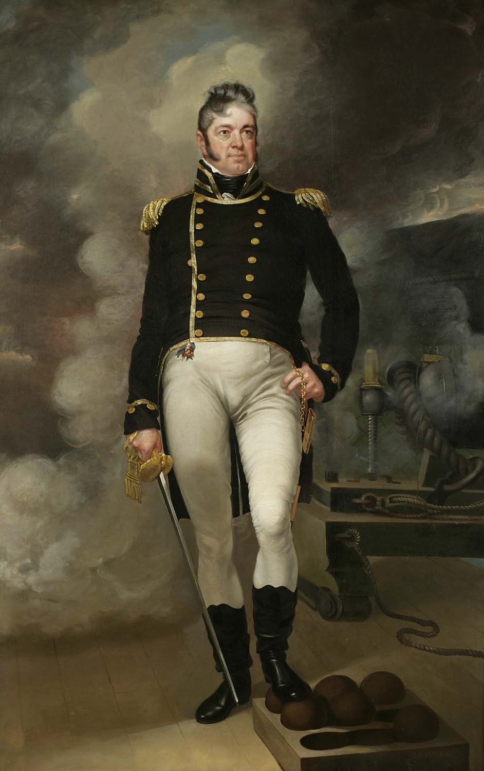
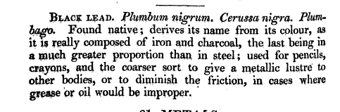
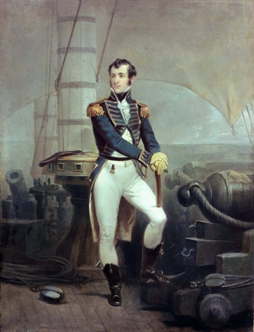
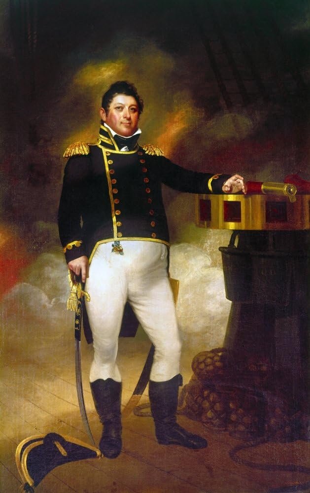
Hey TBE , great progress! I fully agree to your point of view: nobody will really see them - maybe with the exception of those close to the waist of the ship were one maybe may see something below in the main hatch .. Hard to tell. If I look at my old 1/96 Revell-model one really has to try hard to see the guns below that boats stored there. Of course your scale is a bit wider .. but .. When I do research for Old Ironsides my very first view is into Tyrone Martins "Close up" - and today I finally found some time to do so for this questions: The only mentioning of something with color are mentioned for the very first years like this: 13 Oct. 1799 -- "blackening the guns" .. Ships log, Jun 1802 -- Gun carriage trucks had iron rims ... Receipt to Jon Taley, 13 Jun 1802, Samuel Brown Papers 14 Sep 1803 -- "..scraping the gun trucks/axlestress and Black leading them..." Ships log Jan 1804 -- painting gun carriage ring botls and leading blocks .. ships log and for Oct. 1804 -- "...repainting Quarterdeck Guns, they are now painted in light yellow in order to correspond with the patinwork of the quarterdeck.." ... Naval Documents relating to Barbary Wars Also later there is often mentioned ".. scrap´d the gun carriages and put black lead on them " .. or ".. blacking .. main deck guns" .. or "balking long guns" .. "blacking carronades" .. But - as far as I understand this - this may not refer to the color of the wooden carriages - than to the barrel itself. And the "blackening with black lead" may refer to graphite - and in that case was not used to protect the surface but to make sure axcle and the seat of the trunnions. Black lead may refer to something like graphite .. as black lead - plumpum nigrum - was the name of that: In Samuel Frederick Gray, A Supplement to the Pharmacopoeia (1821) black lead is described as Plumbum Nigrum - which seems to be the former name of graphite - although the text specifies is at iron and charcoal.. So I guess "black" is not the right color - and the only color mentioned in Martin´s list is the light yellow - to match the 1804 quarterdeck. I did not find any other hint for colors of the carriage. But: there are lists of colors delivered to the ship: Aug 1803 -- Paint pigments in ship's stores included 305# black, 3 cwt white lead, 3 cwt yellow, 50# green ("verdigris"), and 28# red ("vermilion"). [Receipt for John Osborn, 1 Aug 1803, Samuel Brown Papers, MHS.] and later: 11 Jan 1804 -- Received 15 kegs of yellow ochre, 2 of red paint, 7 small ones of black paint, and 50 gallons of black varnish. [Ship's log, DNA.] the August 1803 list indicates that the ship got "3 cwt yellow". A cwt is an old unit - C for the latin word "centrum" for 100. "hundredweight" is in the US the equivalent to 100 pounds. If the description would be meant in british units (I am not sure if the young US did already used their specific units - I remember some very interesting articles about this in Wikipedia!) .. well, if it were british, its even more: 1 cwt in Britain would be 112 lbs . For us that means: the ship had at least 300 lbs yellow, and 28 pounds of red ("vermilion" - which was a bright and very expensive red - not to be mixed with the cheap "swedish red" which is also known as "Red Iron Oxide". The Jan 1804 list talks about 15 kegs of yellow ochre and only 2 of red paint. A "keg" seems to be a barrel of about 30 - 40 pound ..15 kegs would then be about 450 - 600 pounds of yellow ochre. While red is again in a very small amount available. 2 kegs = 30 - 80 pound. BUT: in Martins Oct. 1804 quote we learn that from NOW on the carriages match the quarterdeck in being yellow.. So if we look for those colors - and take that 2 days delivery as an indicator of the likely use of paint for carriages, we might notice: 1. vermillion red is not very likely 2. yellow, or ochre yellow is possible - and was used at least in 1804 - but obvously something else was common before Oct. 1804. 3. green ("verdigris") was the chosen color in 1812 for the features on spar deck - as we can see in the Isaac Hull model. 4. black was available in suffcient manner 5. red - not vermillion - but maybe such a spanish brown - which the following paintings also would "allow" ... This painting by Alonzo Chapelle (done in 1862) shows Stephan Decture - most likely on board of USS United States - although the rounded rail in the background seems to hint on USS Constitution - still the shape does not fit. The gun carriage seems to be black ? I looked for others - but the color is always hard to tell: Isaac Hull patinted in 1815 for his 1812 victory .. is that a black capstan? Baindbridge seems to be beside a yellow, ochre or brownish carronade carriage .. And of course: the painters did most likely not really care for the PERFECT color of those details. They may just been "typical" paintings for them in those days. There still was no "standard" - and most likely the captains may have used whatever was available and cheap. My personal favorite today: black, [Edit with a day of reflection:] changed my mind: a red color seems to be likely - as red ochre was a typical choice - and what´s more interesting: even when Old Irionsides had her greenish bulwarks and deck details: her gun carriages seem to have been red [end edit] or.. if you like - this brownish spanish "red" - at least either a very dark faint color - or an ochre or yellow color - which most likely also is a bit obscure and not very bright and clear. Your spanish brown is a perfect match in this regard .. but I fear: right now we just can guess!
-
Oh, that's interesting. 😲 I did not notice this lines. I need to check my notes !! 🤔 Seems I did Fall over the same step, I so often complain about at others! The bias of interpretation without real checks.. Just because an idea fits to the total picture does not necessarily mean it WAS like that! 🫣 But: it won't affect your casting process and my intended reconstruction as both point on well before 1807 ... puh! 🤪
-
Excellent work, Haiko. But I have to state: I did find those Savannah guns only due to @Force9´s research. HERE he gave his hints - I just followed his steps 😄 Concerning the short length of those early 24 pounder guns we know from James Fenimore Cooper´s 1853 "History of the United States Navy" about the events of the July 1812 "Great Chase one of the negative effects of those very short barrels: Its clear: the combination of a big rake, high windows and short gun barrels would allow the air pressure at the gun when fired to affect the ceiling of the after cabin. Another effect reported in Tyrone Martins "a most fortunate ship" was that the gun smoke was filling the gun deck with thick haze that it made further operations with guns very tricky.
-
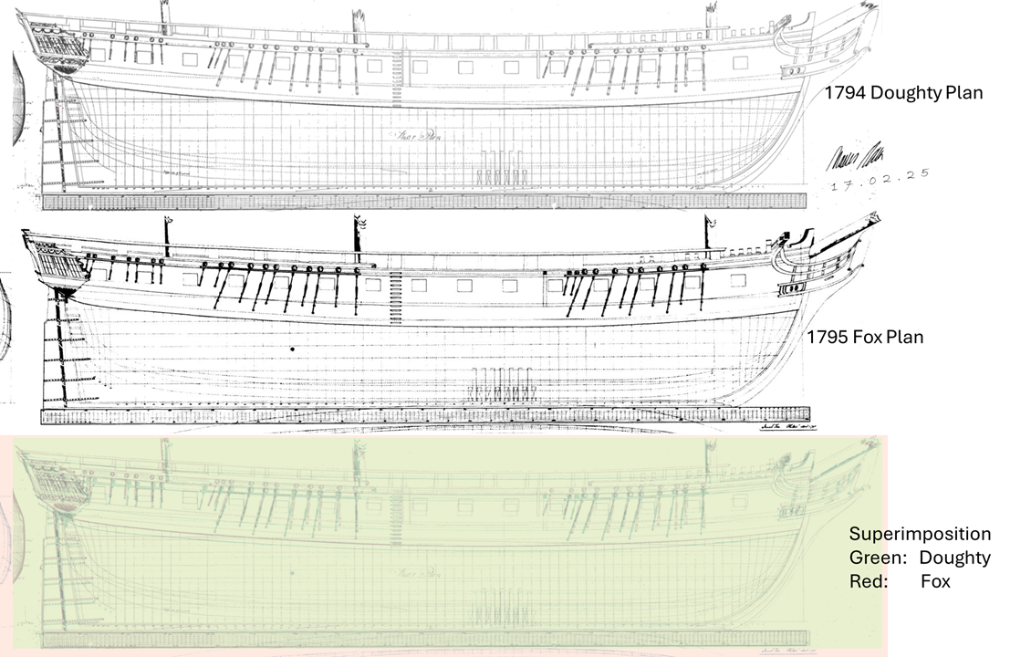
Today I accidently stepped over the 2nd "original" plan of Old Ironsides .. the "Joshua Fox"-drawing. Of course it´s only a poor copy of the original - but its clearly NOT the other - so called Doughty plan we have in the above post. Gillmer compared the two layouts in his Book "Old Ironsides - raise, decline and resurrection of the USS Constitution" and concluded that the Ship itself has more similarities with Doughty´s plans. You may find it in THIS PDF - on Page 99 - and you may download the book. It contains also a lot of other early ships plans - USS Boston, USS Essex, some of the smaller units .. even Gun Boats.. Enjoy!
-
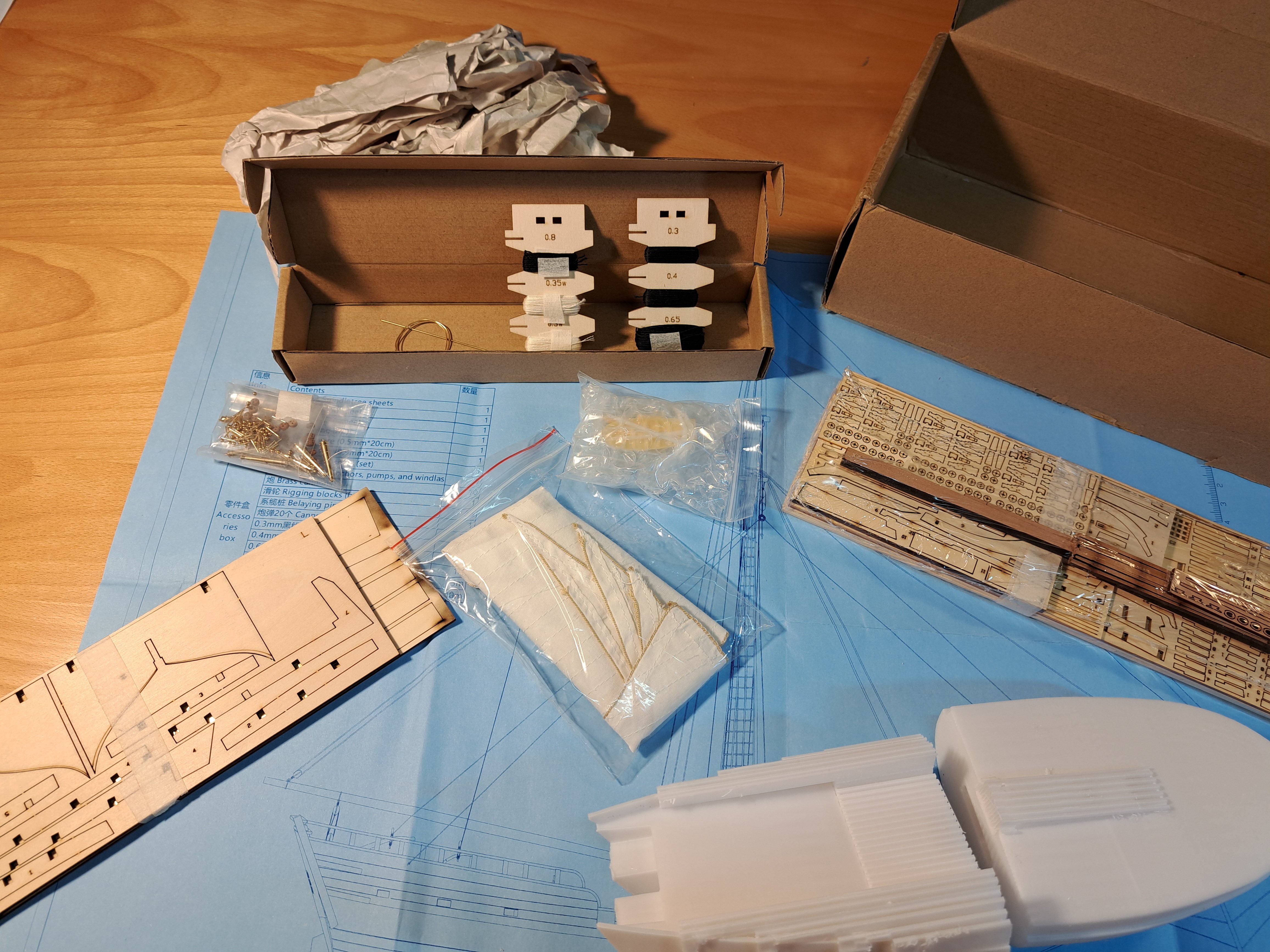
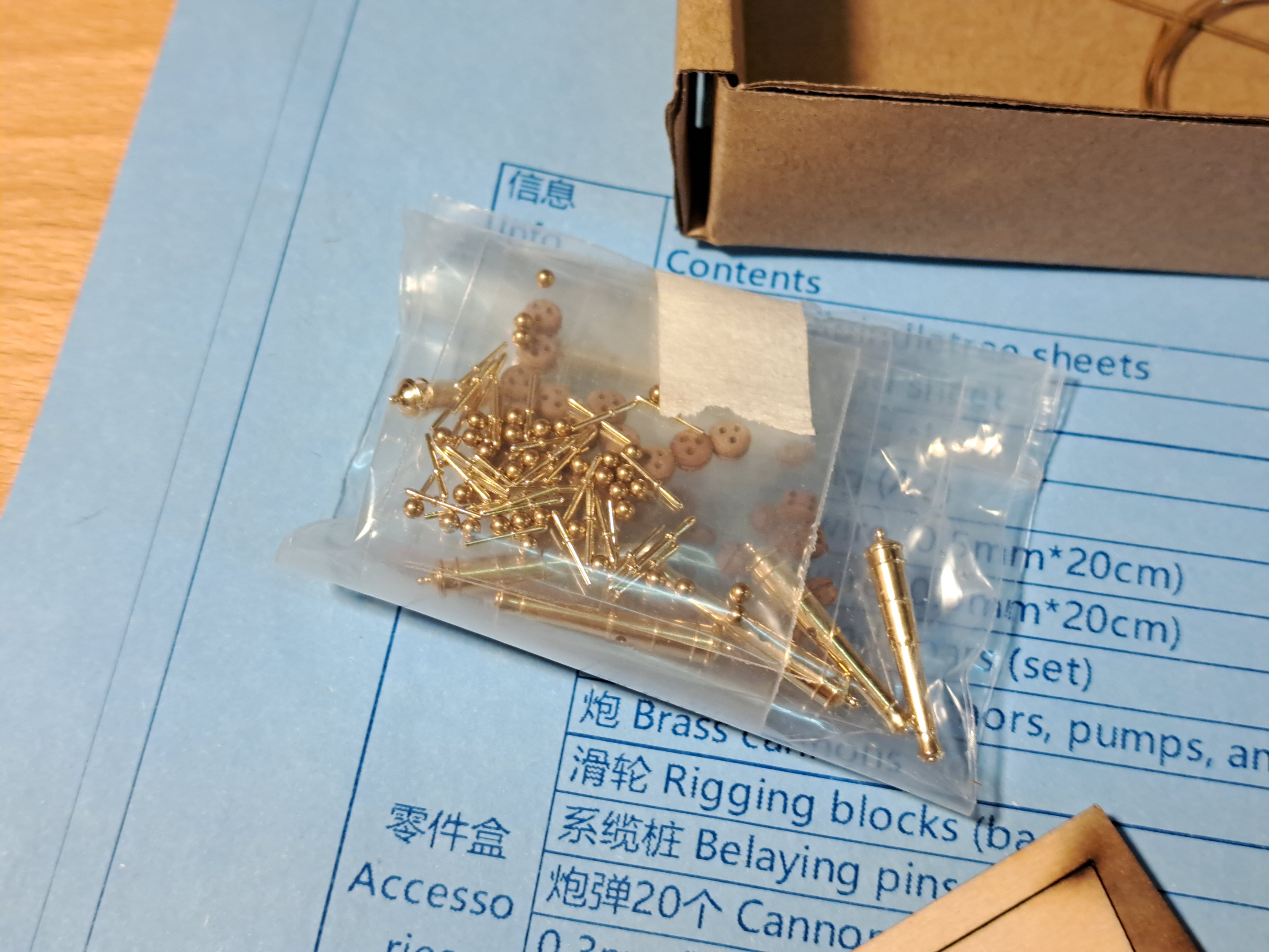
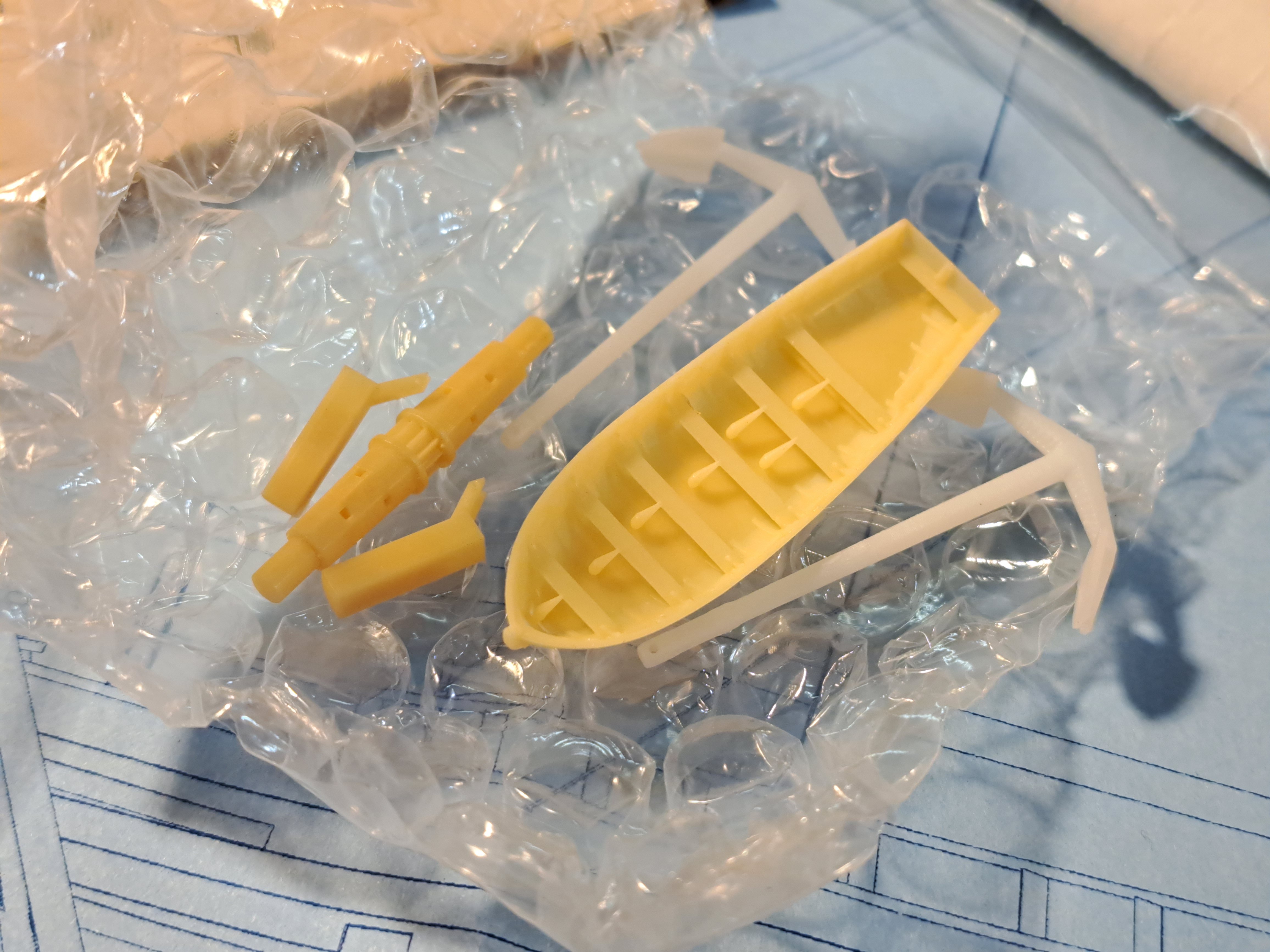
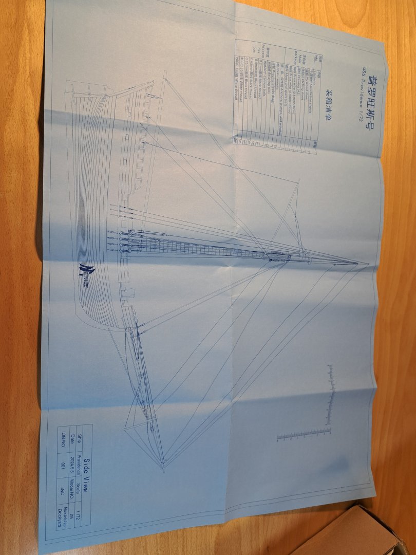
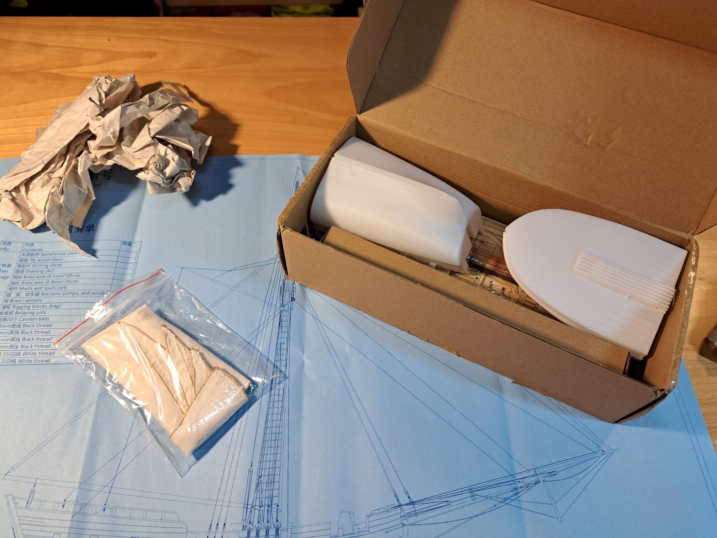
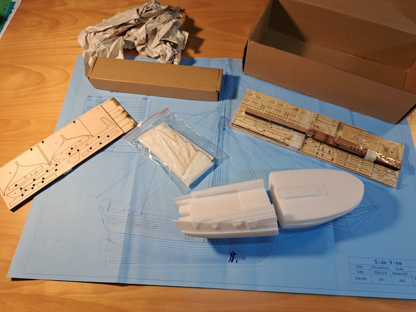
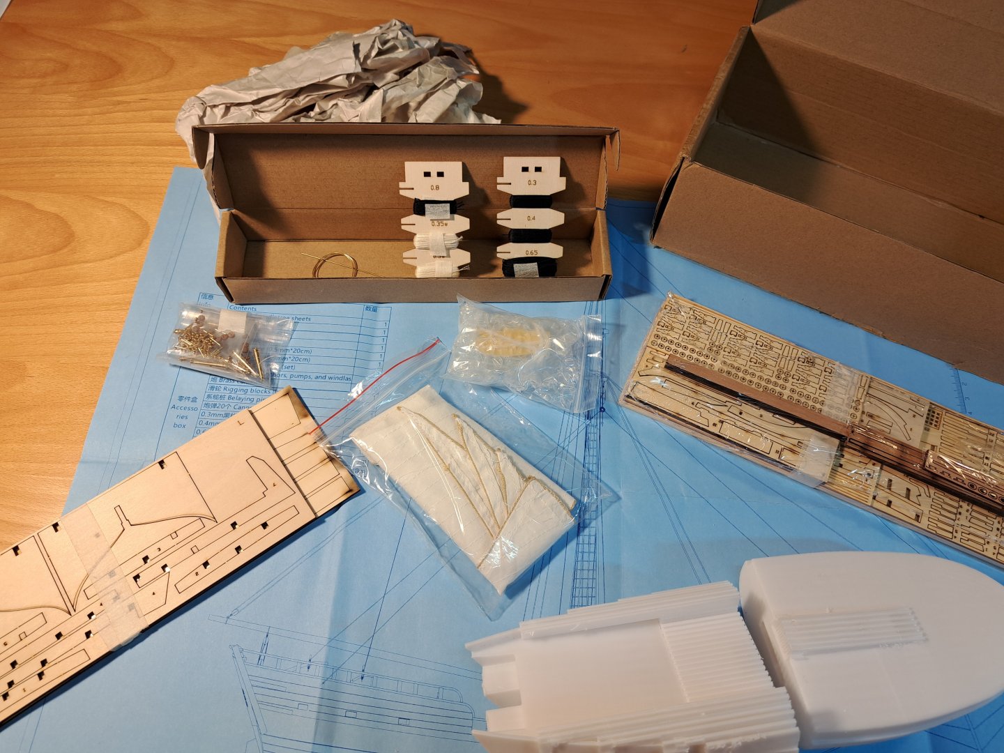
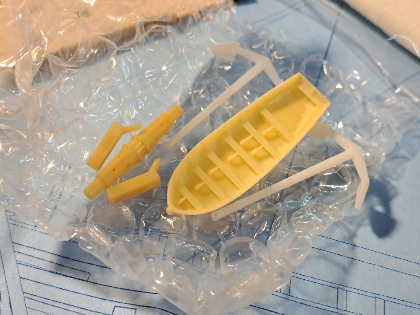
Ahoy there, what´s up Doc? US Sloop Providence, US Sloop Providence .. biiiiiig deal!!! When I first saw the video of the "how to build" for this tiny little sloop I instantly fell in love with that kit. The hull is done by a 3D printed plastic hull - but all the visible surfaces are done in wood. Lasercut wood - exactly in the shape the pieces need for being shaped into their position. After my tryouts with lasercut kits the last years (a viking boat - in fact a slavic boat and a small cutter - which was fun both times) I thought this little kit might be fun too. But .. a banned supplier? Modelship Dockyard being on the list of banned suppliers!? I was asking the MSW administrators for their opinion on this kit - and got a positive feedback. Modelship Dockyard being only the distributor of chinese made kits - and this one not being a copy of someone else: agreed to proceed by admirality! Thanks a lot @Chuck ! I intent to not do a historical research for this one - as I intent just to gain experience in real modeling. My US frigate Constitution will stay my main project and all energy for research will be focused on the big frigate. Nevertheless: here is a lot of stuff to read about the little sloop which was one of the very first US Navy ships in 1775 for what was called the War of Independence. Thanks to all involved in this research. I was starting to read - not yet through the hole thread. Although the purchasing did take a bit longer than announced and after a short and pleasant e-mail contact with the supplier I recieved the little parcel after about 4 weeks. The first thing to be seen when you open the box - the drawing of the final ship: _Y Yeah, but where are the instructions to build it? Only this paper?? Next are the two 3D printed hull halfs - and a lot of wood below: In that smaller box we find threads and metal parts - and some more 3D printed components: The content seems well prepared for the long journey from China to Germany. The plastic hulls of each of the single parcels were intact - with minor damages in some. I found one of the wheels of the gun carriages being broken loose - but still where it had to be - no loss as far as I can see that by now! And the instructions are to be downloaded from Modelship Dockyards pages - which I did and attached here for your reference. Pls. feel free to join my little journey on board of this successful little sloop. I hope to be able to show how this "3D-puzzle" can be converted into a nice little model for beginners. USS Providence instructions v2.4.pdf


-
- 4
-
-
You may purchase it via the publisher: https://www.geymueller.de/de/978-3-943164-45-9 ... and it´s really a beautiful reference for ships that age! By the way: I am a silent follower of this thread - and since I added here something let my add how much I admire your work here!! Beautiful and amazing !!
- 387 replies
-
- 2
-
-
- soleil royal
- Heller
- (and 1 more)
-
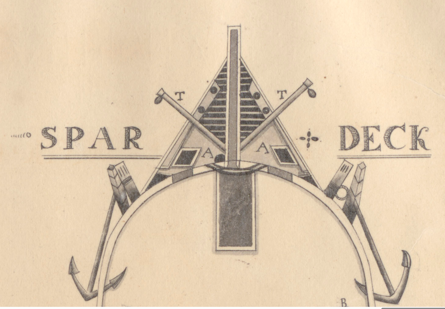
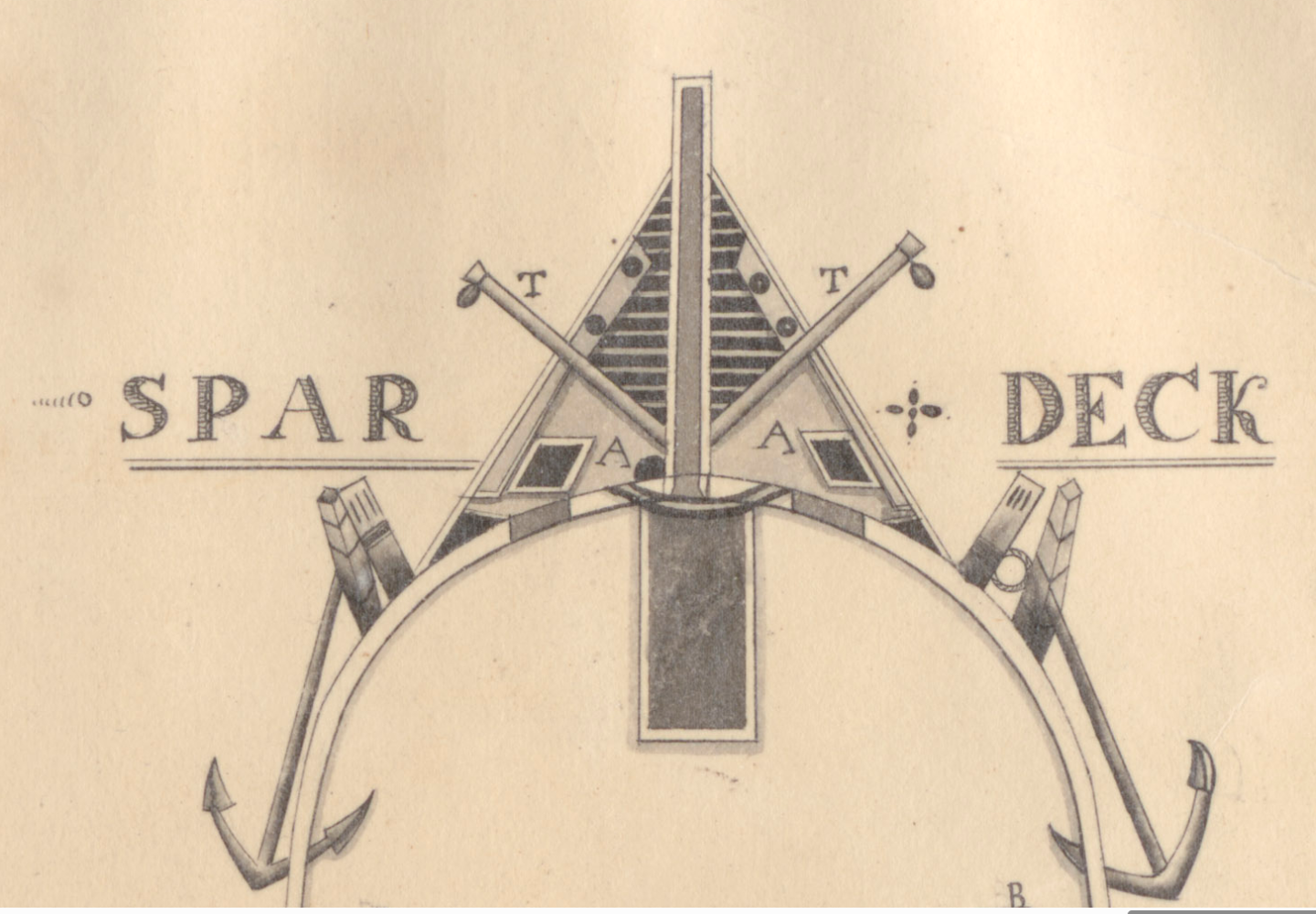
Interesting observation, Pat. I believe that since Humphreys specified those "thick strakes" - as he called them - with their interlocking specifically for strengthening the ships longitudinal robustness against hogging - that they were installed precisely "beside" the future hatches - to not "cut" them by adding the hatches in a later step. Since they were generated especially for that, it would be stupid to "damage" them by cutting in the hatches in a later step. On the other hand: we have no idea whether the shipwrights really understood or even "accepted" Humphreys design. We know for example that Fox was in frequent discussion about many design details with Humphreys - leading to that open quarrel between the two in later years. And then: those written specification left a lot of room for interpretation. And also the know how and tradition of each involved shipwright had impact on the real ship. So any today known written specification may or may have not been followed in the real ship from the start. Those are the open questions we will most likely never know .. But .. if we try to reconstruct something it is - at least in my opinion - better to follow a known contemporary source instead of stomach feeling from today´s point of view. Only exception: if your doubt is justified by another source or indication of some later known designs. We very often do trust "common" known and "pleasing to the eyes" layouts more than unusual ones in - for example - sister ships. Just because something seen in so many models and interpretation it seems to be "right" and therefore we often mistrust a - for us strange - "feature", for which someone finds a contemporary source. Argument: "we don´t know if THIS was done in THAT ship too!" .. yeah - but we also don´t know if the "classical" design was done in THAT ship, right? Example: I found in Charles Ware´s 1820 US Frigate United States Deck drawings that it seems the Frigate had a partly closed planked head. "A" is declared as "wash deck pumps". That black tetrahedrons seem to indicate either a rising or - as I believe - a certain well or "tub" for the wash deck pumps (pumping sea water). So the sailors would be able to get sea water to wash their hands, their body and even clothes (laundry was often done in the ships head). And you may notice that strange feature along the outer edge of the head in that area marked with "A". I believe these are a pissoirs on left and right side of this area of the head - for the sailors. The wash deck pump would therefore "feed" a certain sink (the black tetrahedron), the pissoir and the seats of ease .. If you look at the color of the deck in that area: its represented plain - while the front of the head - with those seats of ease - is black and white - most likely a grating, right? Source: Frigate_United_States_Ware_-15_-_NARA_-_3281884.jpg (9931×6725) Now imagine I would represent that design on a Constitution model : for sure there will be voices stating "well, you do not have any proof that THIS design in US Frigate United States in 1820 was also existing in US Frigate Constitution!!" - which is true! But on the other hand: I don´t have any proof for any other design in Old Ironsides early head designs.. Right? Back to our planking issue here: I would assume the shipwrights followed Humphreys specification - and valued the stiffening properties of the thick strakes - and therefore hand them installed before the hatches but according to the hatches dimension - and therefore had the needed planking tapering pattern "predefined" - just as Haiko was doing on his deck. But.. all that´s just "guesstimation" only 😄 Always remember Captn. Hareblower: "Eeeh, I could be wrong, you know?"
-
I don´t KNOW what was done in those days.. and I guess we will never know that. But I guess I would follow the tapered scheme here too. It just seems more logical to me. How did you manage to do that "tapering"? Did you cut each planks width individually?? And: if distances between hatches or other obstacles can be filled with only one (typical) plank, don´t try to follow the planking schematic beside the strakes. A longer single plank is always preferred - as it is more robust than 2 planks meeting on a deck beam. I am curious how it will look after sanding the surface. I am pretty sure it will look just perfect!! Can´t wait to see the result. You are doing a great job here!
-
"Don´t shoot until you see the white of their eyes!" But on the other hand: we should be aware that the expression "in the tops" may have been misunderstood by our author´s here too .. because they may have done the same misinterpretation - if it is a misinterpretation! That tread started, because we were thinking about "what is meant by "in the tops"?" And many of us think about the f(s)ighting tops - as this is the most common known expression with "tops", right? But maybe O´Brian did the same thinking? He for sure was very good informed about the age of sail. He may have read about "hammock stations in the tops" - and concluded: that must be in the "fighting tops" .. But maybe sometimes the hammock stanchions on top of the rigid bulwarks in quarterdecks and forecastles were also called "tops"??? And by that a myth may have started .. and by repeating it, it seems more plausible... Pls. don´t get me wrong: I don´t say it IS wrong. I just want to hint on the fact that I never seen any hammock stanchions in a fighting top so far. And I admit: I never looked for them up to last week - but .. I don´t recall any. ... we need more evidence to be sure. It would be good to find visual evidence by old models done in those days. Models showing hammock nettings and stanchions along the bulwarks - AND in their fighting tops. Up to now I do not recall any. Does someone?
-
Hello Haiko, Humphreys specification was done in 1794 or 1795 as far as I remember. And the 6 shipyards did not follow them 1:1 - as they had to deal with what was available and how they interpreted his specifications. And I guess nobody expected them to follow them 100%. Ship building in those days is not comparable with todays way of work. The specification weren´t that precise and the shipbuilders had a huge amount of freedom in interpretation - especially compared to today, where we have 3D CAD data of the vehicles to be build. And even today: deviations in the scale of several inches or centimeters is not a rare thing in todays bigger ships. They had to deal with wood! And they made it fit to where it had to fit! Individually for each plank and each component. No ship was the same as another - even if it had the same "concept" or "architecure". Even if we consider the fact that the young United States had huge amount of high quality wood (especially compared to the British Royal Navy which by then had exhaused British forests and had to purchase wood from everywhere); and even if we consider that the shipwrights did their very best to provide the highest quality (the most important specification by Humphreys: as his idea was to have rather a smaller fleet of best possible and durable ships than a bigger fleet with poor build vehicles): we need to respect the fact that pracmatical solutions to the acutal situation in the shipyard had to be done. We know the "deviations" vs. the "specifications" and / or "typcial habits" the scientists found in the VASA compared to any shipbuilding tradition involved in her build. The sometimes "improvised" pattern of planking, differences and unsymmetries between left and right bulwarks, etc.. Sometimes it was build as it worked out best. So a deviation of several inches compared to Humphreys design would not at all thrill and bother me. In addition of course to the fact that the model is build in a scale which does rarely allow that accuracy - and any observer would not be able to differentiate "correct" from "wrong" .. Have fun! Marcus
-
For future reference let me link here a thread in which we discussed the sweep of the main wale vs. the sweep of the gun ports (meaing the sweep of the gun deck). I always wondered what made the Doughty plan so much more elegant then todays ship. And beside the open rail which gives the ship a lower profile in the side view I think its the more curved sweep. As a short summary: I could convince myself (and I hope my comparision was convincing for others too) that the three big frigates were not following the sweep of Doughty´s beautiful drawing. While US Frigate President and United States even seemed to have had that exact same sweep in their planks compared to the gun ports and therefore the gun deck, it seems the Old Ironsides had a bit more elegance - and that it had since the beginning a bit more curvature in her main wale compared the the gun deck. And today´s ship still seem to follow the same lines in this. For more detailed info: click on my and follow this thread
- 16 replies
-
- 1
-
-
- constitution
- revell
- (and 1 more)
-
Hey Haiko, I very much like your approach. And the way you prepare that gun deck with these interlocking strikes will be very close to what Tyrone Martin found as her earlier layout. Your deck planking matches his sketch pretty close and the more I look at it, the more I like it. Do you manage to generate the 6 feet white oak from hull inwards (as Humphrey specified)? Or is that outer strake too close?
-
Why did I miss this? Excellent work. Looking forward to see them on deck!
- 233 replies
-
- 1
-
-
- Model Shipways
- constitution
- (and 5 more)
-
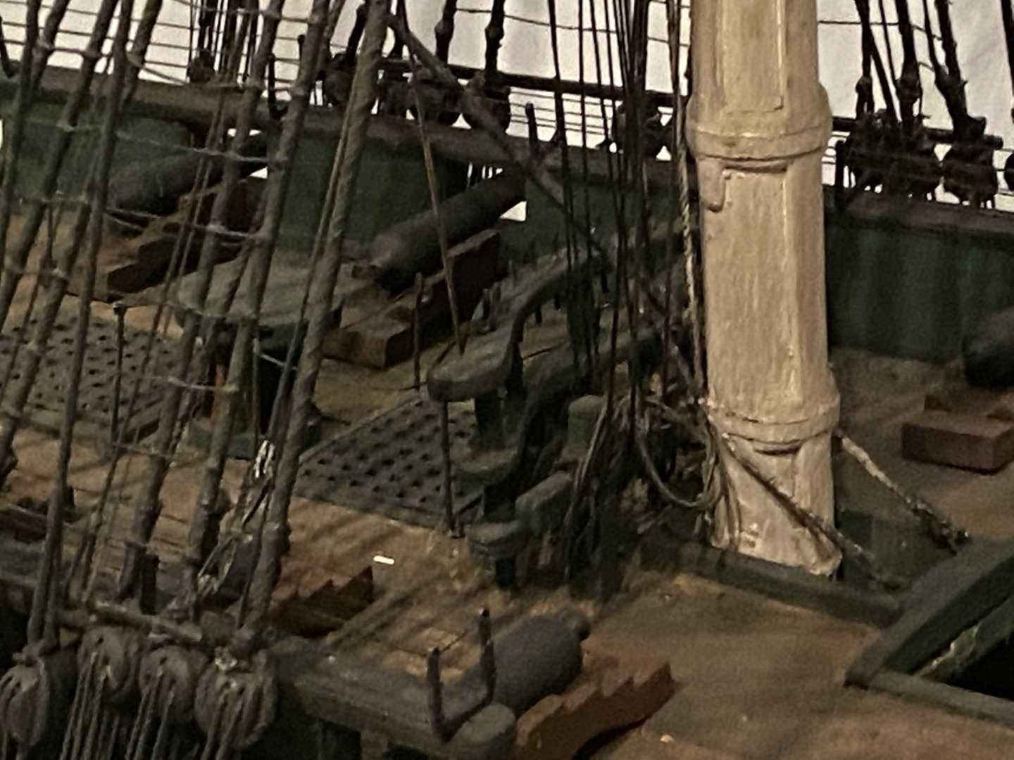
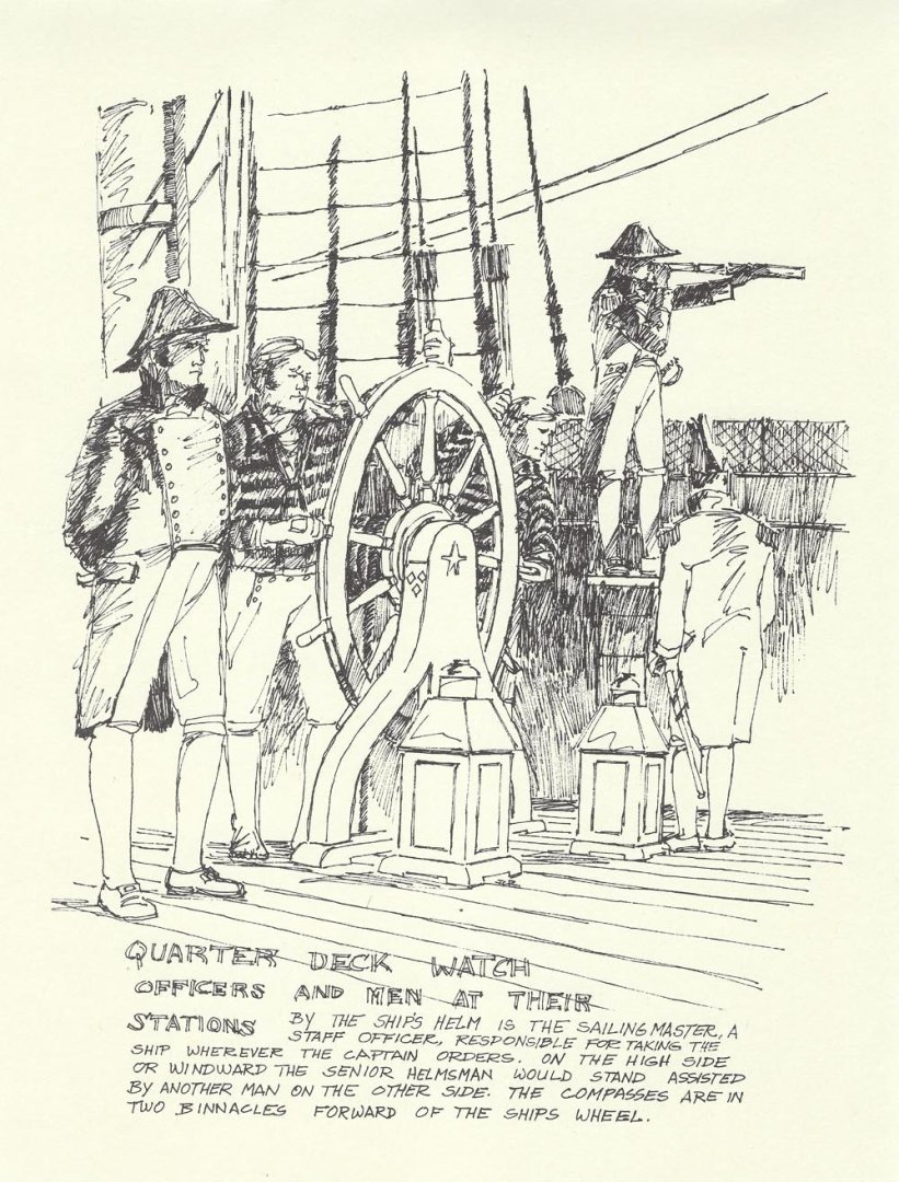
hm.. Broke says: "I am going aloft" in the beginning … so here he still is on deck. When he raises his voice and calls for Mr. Wallis he asks him to "come down". Then the next sentence I don´t understand: "between them Broke and Wallis heave his sixteen stone into the sighting top" .. "and Broke carried on to the masthead" .. that 2nd statement seems to indicate that they did climb into the fighting top - while Broke carried on. What is a "sixteen stone"? I don´t understand that first part of that statement. "between them B and W heave his sixteen stone ..."?? But in general it seems to be the fighting top - as they observe the Chesapeake and another lad even climbs to the mast head where he had a better view on the scene. I would not be surprised if they called it sometimes also sighting top - as a lookout would be placed there. I have been wondering if term "sighting top" could also refer to this thing here: in the background a watchman is standing on a board - a "sighting top" ??? - and would have a perfect view on "hammocks wedged in the nettings between the stanchions" .. right? But all that is "guessing" - and not "knowing" - and .. as mentioned: O´Brians text seem to hint on a top in the mast more likely.
-
Hy Joachim, are you sure O´Brian describes a "fighting top"? .. because the text describes "hammocks wedged into the netting between the stanchions" - that may point on those smaller hammock nettings on top of a ridgid bulwark too, right? .. well, o.k. "two one-pound swivel-guns a side" may hint on a fighting top.. but could also be the bulwarks of a ship as we know that for example Cook´s Endevour - as so many ships - had swivel guns on her caprails too ... hm.... The statement as such does not make sure we talk about a fighting top, right? Does the text say earlier or later that Mr. W?? and Jack are in the fighting top in that scene?