
HOLIDAY DONATION DRIVE - SUPPORT MSW - DO YOUR PART TO KEEP THIS GREAT FORUM GOING! (Only 13 donations so far - C'mon guys!)
×
Marcus.K.
-
Posts
351 -
Joined
-
Last visited
Content Type
Profiles
Forums
Gallery
Events
Everything posted by Marcus.K.
-
Thanks gentlemen for this discussion! Everyone showed gentlemen attitude and nobody tried to duck and hide ! My personal summary: the wording of those (written) statements may be misleading - more evidence is needed to judge the word "top" may refer to several things - among them the fighting tops, the "top" of the bulwarks or a lot of other things being "on top" of something else. protection for the marines in the fighting top not unlikely ! hammocks were also used to protect the ships deadeyes and lanyards that was a new information for me and those paintings are very interesting! Maybe that was done more to protect the "thinner" ropes of the lanyards - because if they would be hit by even a smaller shot by a handgun and destroyed, the stability of the thicker, stronger shroud and therefore the mast was in danger. The hammocks would protect those more "sensitive" weaker lanyards from lucky shots. hammocks - if used in the fighting tops - would not be stored in any "cranes" or "hammock stanchions" as on the ships bulwarks (not needed weight in the mast during normal life!!!) - as there were non. But sailors knew how fix them and maybe they were only used to hide from view - maybe not to catch the shots. I guess it depended on the habits of each ships crew how they did this. I will too look for any other hint and provide info´s if I am lucky
-
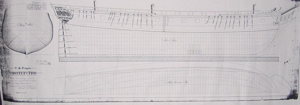
 Hello tmj, I recently stepped over a drawing, which seemed to be older than the "traced" PDF the Navy Heritage departmend spreads as "Doughty´s plan". In fact that PDF says in its header (and that bottom line) that its just a copy of a dawing from "C&R Plan N° 38-4-2-a" if I read that line in the bottom correct: It is unclear who did this tracing - and when! When I was learning "technical drawing" (I am a dinosaur: I learned to do it with pencil and ink on one of those huge drawing boards I still own - before I learned to use CAD!) the information in a header with name of responsible, date and drawing-number was the very first thing which was checked by our teachers. A drawing with a gap in this information was not accepted. I found out there in world wide web ONE drawing, which seem to be older - and may be this C&R plan.. but unfortuntly its not really readable! .. and unfortunatly without any hint for it´s origine. Why do I think this is an older version? Because the lines and texts written in the hull seem to match perfectly with the PDF´s .. but the text in the PDF´s header on the right side misses - and instead it has it´s seemingly older header on left side. More importang: the rim of the paper seems to be much more timeworn and frayed than the PDF´s rim. But would Doughty have specified his plan as "Constitution"? Do we know if Doughty did specific drawings for each of the three big 44 frigates? I am frequently reading that there are "Doughty Plans" and "Fox Plans" .. but I never saw any plan refered to Fox? In the PDF Doughty is at least mentioned - but as we see: the PDF is not "his" plan - but a copy. Also the whereabouts of the original(s) is pretty obscure. No one seems to know? .. and more thrilling: no one seems to care?? I was asking the USS Constitution Museum and the Naval Heritage Command - but just got this PDF you have too. The precision in answering was pretty poor. But I have to admit: that was some years ago - maybe I should try again. Anyone any idea?
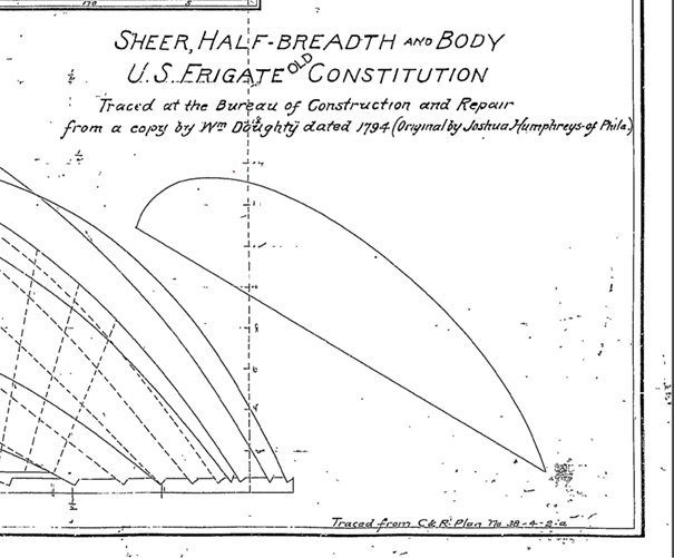
-
Thanks Henry, that looks like perfect knots for connecting to the stronger top and bottom rope - and for the "crossing" of the thinner zig-zag ropes. Great input! Much appreciated!!! I struggle a bit to understand, how the thin ropes would be treated at the eyes of the hammock stanchions.. A knot like the one shown here would not seem very simple. I was thinking that the thin ropes would be streched from thick bottom to thick top rope. Although thinking about it I realize that the "crossings" should be fixed with each other to avoid that the net would get in disorder - and "opens" too much somewhere.. So I guess your proposal are pretty good for the "pane" of each field between stanchions. If anyone has an idea for the eyes of the cranes ..?
-
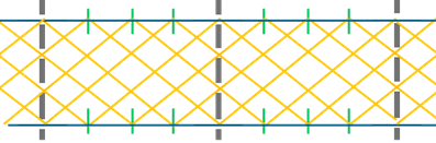
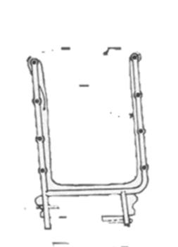
Mates, lets assume I am a landlubber getting the task to create the net for hammock netting - and we on our proud ship, we want to do it "beautiful". My task is to use the hammock cranes with 4 eyes in each vertical post .. and of course there is a rope on top and on bottom of each side of the hammock crane in those outermost eyes. This is a Hammock Crane as used in the American Navy until about 1812-13. Four eyses in each post .. Our Captain ordered to have a zig-zag-shaped net - like this: The thick verstical lines with eyes are the hammock cranes the two horizontal lines are the limiting lines along the ship on top and bottom. Yellow are the zig-zag-lines generating the net. Green indicate knots to fix the zig-zag-"ing" lines .. It is easy to find those green "spot" as they are just the mid in between two posts - and then again their mid. A position easy to define as we just have to fold a rope 2 times to specifie that quarters. The knots itself may be done by the horizontal line - or by the yellow net - or by an extra short line? Ignorant Landlubber as I am: I wonder: which kind of knot with which rope would the boatswain accept? Master of the Ropes, Keeper of the Knots, may I seek your wisdom?
-
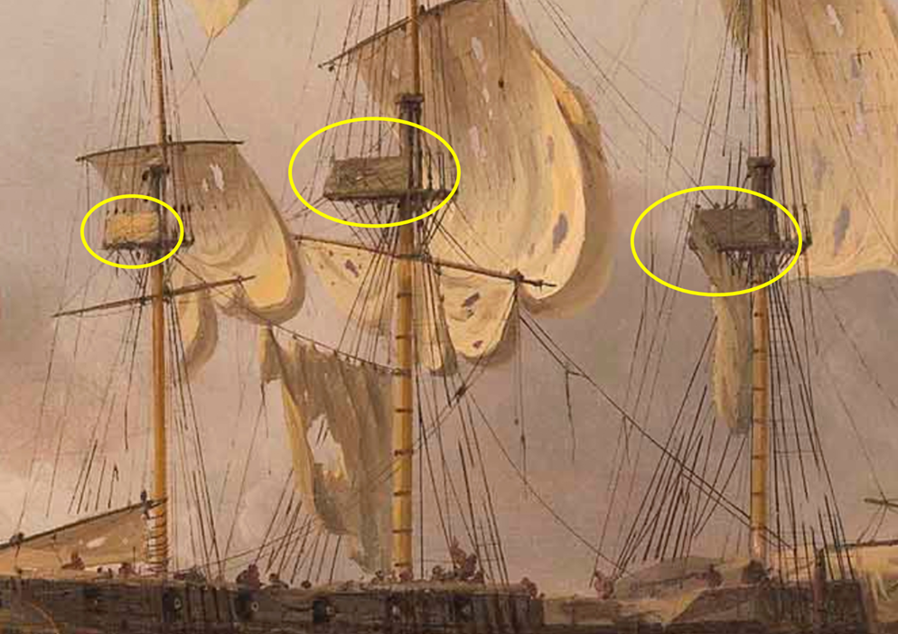
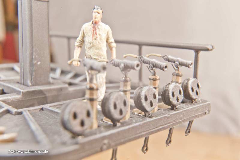
Ah - you mean those things? These are just rails for the fighting top - here "closed" with canvas. Although possible I do not think that those show evidence for having hammocks up there.. This one is done by @dafi - without the netting or canvas - but clearly a simple rail. The rails usualy war just simple rails - no hammock stachions. Or does anyone see any other evidence for hammocks in fighting tops? Or ... any other explanation for the word "tops" combined with storing hammocks in Old Ironsides?
-
Well, I think that has a reason: while the decks usually never were painted and the discrepancy between wooden planks and caulking dark brown, nearly black was easy to recognize, it would - on the other hand - be hard to see that different color on black painted ships hulls. And even where there was an ockre paint: that paint would most likely been painted over those caulking gaps. Although I admit, that one may doubt the paint would stick there a long time ... But again to the decks: there you would have this frequently "washing" with "holystones" - a process which frequently would make caulking more prominent to the eye - while the hull was only washed by seawater...
-
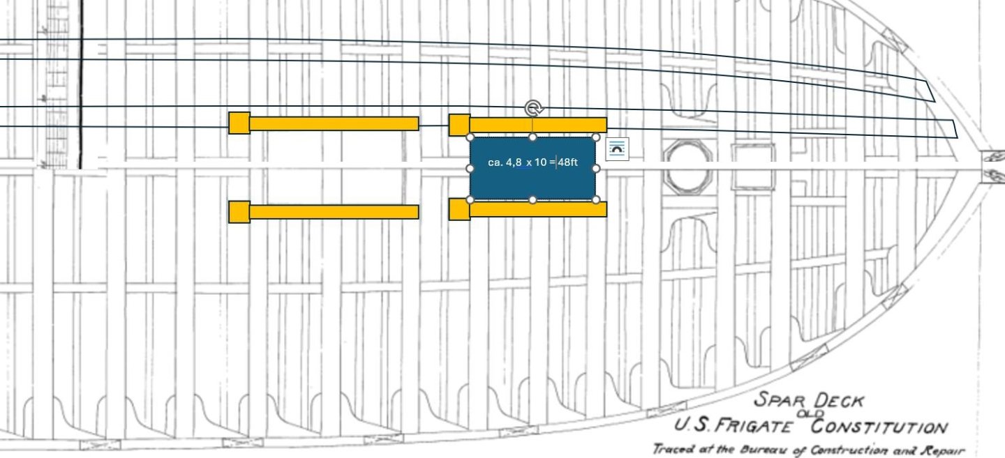
This especial discussion came from HERE. I measured the room between the cable bits in the 1817 Waldo Plans .. and .. there is less than 5 foot room in between those knees! Maybe a bit more - if the knees would be a bit smaller than the posts in the deck. See the sketch of a modified Waldo Gun-Deckplan - including (marked orange) Cable Bitts - and indicated 4,8x10ft platform for the stove. I used the plans scale as reference. Pls. not that the cable bits were moved one position to the stern - having them beside the "fore hatchway" - exactly the Ware Deck Plan for US frigate United States indicates this. In today´s ship the cable bits are moved on position forward - the one beside the for hatchway is now beside the foremast. In the USS Constitution Museum´s Blog : A stoved Boat the author Matthew Brenckle indicates that the stove installed in 1803 might have the height of only 27 inches high - as this is a dimension shown in a delivery note. He states that this oven must have been far to small (also comparing the mentioned price of only 100$ with a price for another later 1827 delivered oven for about 2300 $ ... and I kind of agree. ... And therefore I doubt that this 100$ stove was the main canboose of the ship. I think its more likely a 2nd stove - maybe for the captains pantry or so? ... or maybe for additioal meals. Boudroit shows in his beautiful "74-gun ship" books, that they had several ovens in those ships - even a baking oven for bread. I doubt that our frigate - although being designed to compete with a 74-gun-ship if the weather allows - had a baking oven. Such a big thing would have been mentioned, I guess. But Boudroit shows also several smaller ovens and holding furnace - which would maybe not have been mentiond in the official bills (or may not have been filed) - as they were comparably more cheap (see: 100 $ vs. about 2000 $ !!). This 1827 stove Brenckle points to - showing a drawing for "a frigate" has a width of 6 feet and 3 inches - and that may just fit between cable bitts - if they were moved by 1827 and were also widened a bit. Or: they were for another frigate ? I thinks I need for my 1803-04 version to go for a more slim design for my model - as I will make use the Waldo Deck design. That leads to a ca. 4.8 feet times ca. 10 feet flagstone podest for the oven .. done most likely in granite as it was available in Boston area that time and as this is a very robust and persitant support, being able to widthstand heat, salt water, mechanical stress What do you think about it?
-
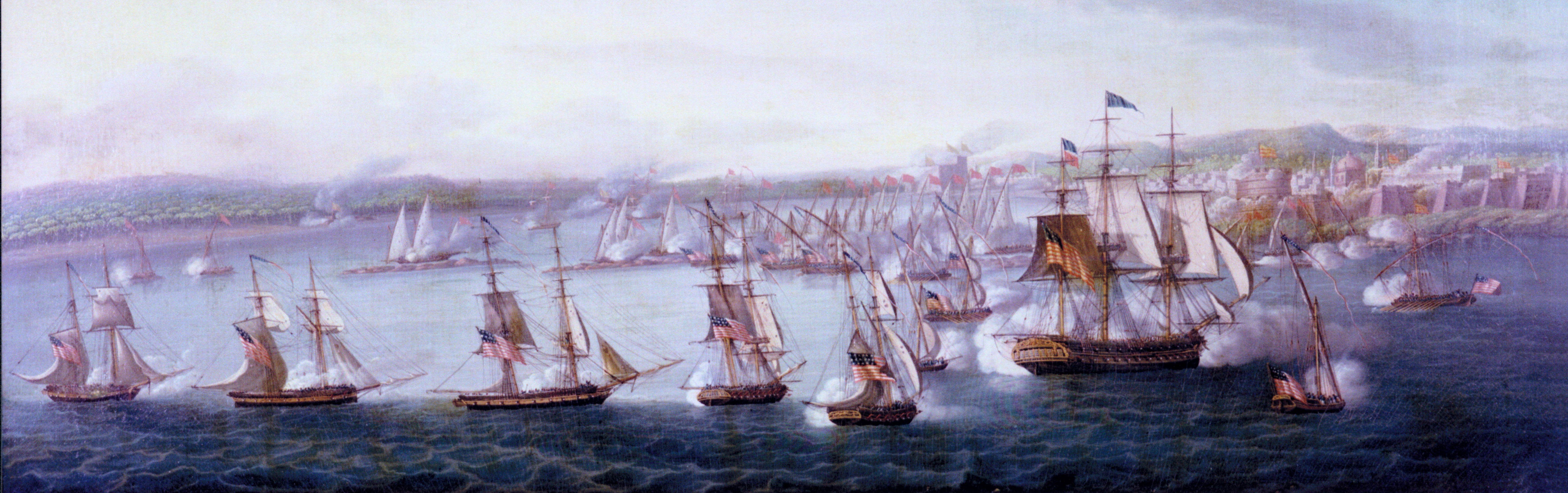
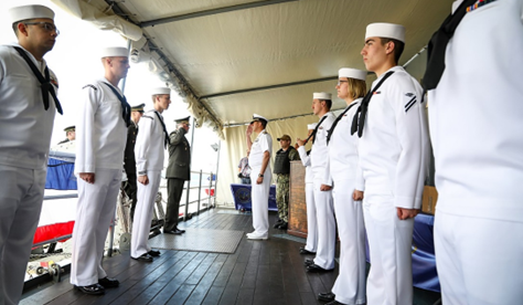
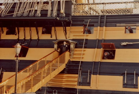
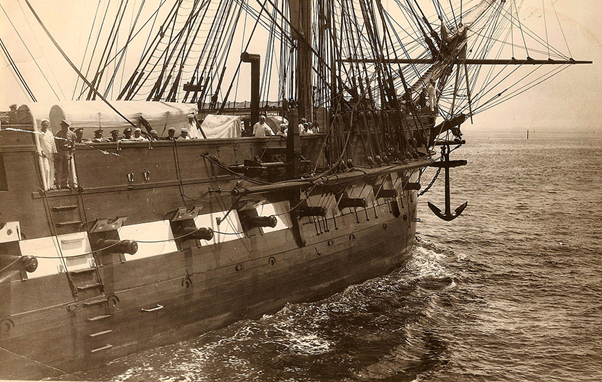
Thanks to your support here and in other forums I learned something by now. We all know that scene: a high-ranking officer, a captain, a commodore, an admiral or maybe even the president, enters the ship's deck. The Boatswain's pipe whistles its typical tone, signaling some sailors in their bright, clean, white uniforms to line up left and right and to salute the “VIP.” Ukrainian Chief of General Staff Gen. Viktor Muzhenko piped aboard USS Mount Whitney (LCC 20) by Capt. Richard Aguilar (July 16, 2018) – 8 sailors prepared for the salute The sailors performing that ceremony are called “sideboys” (although by now female sailors are nothing unusual in our navys). The process seems comparable to an honor guard when a foreign president or another high-ranking official visits your government’s representative, and diplomatic protocol calls for a “reception with military honors.” But there are differences: • The sideboys are never more than 8 – sometimes 6, in some cases even only 4 or 2 of them – depending on the rank of the visitor. • They do not present their arms – they are not armed at all. • They are positioned not in one but in two lines, forming a guard of honor. • Depending on the rank of the newcomer Navy Marines may line up as honor guard too. The details are strictly regulated in the United States Navy Regulations. Depending on the rank of the visitor she/he can expect a certain number of gun salutes, of musicians performing “Ruffles and flourishes”, which is honors music by fanfare, maybe a Navy Marines honor guard but always the mentioned sideboys. Cmd. Crystal L. Schaefer (77th commanding officer of USS Constitution) saluting her sideboys honor guard while taking command 21th of June 2024 In the diplomatic counterpart, the military formation is: • Very often presented only on one side of a red carpet for the host and the guest. • Presenting their (unloaded) arms and being examined and saluted by the diplomatic guest and their host. • Their number is that of a total company or even battalion. • Often more than one individual military unit is presented. then Vice-President Joe Biden visiting Beijing in Aug. 18, 2011 inspecting the honor guard consisting of army and navy units Why is that? Because the origin of both traditional ceremonies is different. And their original tasks were and are today different. The sole common objective is to pay tribute to the VIP. The “diplomatic reception with military service” – as specified in the Vienna Convention on Diplomatic Relations – is done to • express the host nation’s readiness to protect the country’s sovereignty and • emphasize that the VIP is now protected by a strong guard while being a guest. That is why the guest is allowed and expected to inspect the guard and their arms in detail to acknowledge their competence for this safeguard. On a Navy ship – depending on the rank of the visitors - the ship's marines corps too perform a guard of honor – as a comparable symbolic gesture. But at first the sideboy salute ceremony will be executed – and it has a completely different origin: When navies consisted of wooden ships, the bigger vessels rarely docked along a rigid pier. This was due to: • Risk of damaging the wooden hulls by being pushed into the pier by changing wind or waves. • The fact that many harbors were not deep enough to allow bigger ships to enter closer to the shoreline or piers. • Preventing sailors from desertion. Usually, a bigger ship was moored more outside the harbor and accessed or exited by using boats (like a Captain's Gig, an Admiral's Barge, etc.). The boat was placed alongside the big ship, and there – somewhere close to the ship’s waist – was usually a rigid wooden “ladder”: the “boarding ladder” or “gangway”. These were wooden steps permanently fixed to the ship’s hull, allowing climbing from about the waterline onto the ship’s bulwarks or upper deck. In some cases – like in some British ships of the line with more than 2 decks, e.g. HMS Victory – there may have been entry openings in the hull on the second gun deck level, which is about the same height as the upper deck on our frigate. HMS Victory´s Boarding ladder and its entry port (the modern gangway on left front side would not being used in its active time) Since high-ranking officers and officials were often quite aged men - marked by battle scars, dismemberments or sicknesses, and not that strong and agile anymore – they sometimes needed assistance. Also, sea and weather conditions might sometimes make that climb a challenging one. That’s where our “sideboys” come into play. Chosen sailors had the honor to place themselves beside the gangway steps – left and right – to assist and secure the guest while climbing upwards. Were the guest too immobile or the sea conditions too critical to risk that way along the ship's side, he (or she) was hoisted with the help of yardarms and sitting in a “boatswain’s chair” – just like a load – onto the ship's deck. That hoisting was also done by the chosen sideboys, who then had – just as at the gangway – a huge responsibility for the comfort and safety of the high-ranking guest. Today, in the age of steel ships, even big vessels are docked along rigid piers, and the gangway is now a wide and long plank with rails on both sides, like a pedestrian bridge, making access to a ship not that dangerous anymore. In modern times sideboys have to be present at the bulwark entrance when our guest is putting his or her foot onto the ship’s decks – as the ship’s crew guard of honor, to welcome and salute the new guest and to symbolically guarantee comfort and protection from all maritime adversities. This is where today's sideboy tradition has its origin. In about 1800, when ships were still wooden, the three big frigates (US Frigates United States, President and Constitution) were used as squadron flagships. Those big frigates would have been seen in the young independent colonies as we see a nuclear-powered aircraft carrier today. They were – at least in length and sail power – on par with the world’s biggest and most powerful ships of that time. Shure, they did not have the fire- and manpower of a ship of the line – but their batterie was meant to compete with even 2nd rated ships (two-decker battleships) in case of bad weather (when the battleship was not able to make use of its biggest guns in the lowest gun deck). And their sailing performance was meant to outsail them in good weather (when a battleship was capable to outgun the frigates impressive 24 pounder battery with its even bigger guns). So, they might not have been seen as the absolute top predator on the seas – but due to their different design, battle tactics and strategic task they were among the cutting-edge technology of the time. They were the biggest ships in American harbors. Of course, sometimes British or other nations' ships of the line were visiting. But remember: Old Ironsides' total length is nearly the same as the British three-decker and Lord Nelson's Trafalgar-flagship: HMS Victory! These American Super Frigates were big! And they were the pride of the young navy – used as ship of the state, to impress and sometimes to even intimidate. And they were frequently visited by high ranked officers, diplomatic personnel and important “VIPs.” Besides the frigate's captain, there usually was a commodore – a squadron leader – on board. Both men – and all other VIPs - regularly had to be honored with their “safety guard” on the ship's side gangway while taking command, while entering, or leaving the ship. The sideboys needed to be placed on both sides of the regular steps, and therefore there were either elongated steps or additional steps to allow the sideboys to be positioned. For me that at least provides certain evidence that the big frigates – as being flagships of the young US Navy in those days – had wooden boarding Ladders and additional 3 steps per side for their sideboys and their high-ranked guests safety. I guess I will try to represent those 6 additional steps and I think I may try to even represent that ceremony in its original tradition. If I represent the ship as being moored I may add a commodore arriving in a boat while his sideboys are waiting at the boarding ladder and 2 of them on deck at the bulwark. Not sure if he had the right to get 8 of them (6 on the ladder and 2 on the bulwark) - but I guess a commodore would be treated at least as today a vice admiral? Those additional 6 steps are a tiny detail – and not visible anymore since Nicholas Cammillieri’s 1824 portrait of the ship. [USS Constitution Museum Collection, 1729.1] in any painting or photo later on. But: they seem to have been in place between in the ship’s early years – at least until about the end of the War of 1812-15 – when the US Navy received their battleships – which then took over the function of being flagship. From that time span on only the single boarding ladder is being in place – until today. USS Constitutions boarding ladder c.1931-1934 Let me know your thoughts about it.


- 16 replies
-
- 2
-

-
- constitution
- revell
- (and 1 more)
-
Welcome! According to Wikipedia and THIS page this may have been the first ship, your GGGGrandfather did build - from idea to launch: The Courier Seems he just participated in smaller vessels before - but started with clippers right from the beginning.
-
Well, there are hints, that the late 1804 got a billet head already. https://ussconstitutionmuseum.org/2017/03/03/bow-decor/ And here is a beautiful building log for a 1809 appearance: https://www.segelschiffsmodellbau.com/t7612f264-USS-CONSTITUTION-Bauzustand-Wasserlinienmodell-58.html#msg206074 There may be some bugs in it - but its a true beauty. 1809 of course there have been some changes especially in decor design (as there was an "update" done in 1807-08). Its a bit hard to tell what was done with which results as there are only verbal descriptions ... and I vote for a lot of similarities to the Isaac Hull model in PEM, Salem, which was done by sailors for Captain Hull after the glorious battle against HMS Guerriere 1812. For the pre-1808 decor we also have not much reliable sources. Some descriptions in letters about intended or observed designs and those beautiful paintings by Corne.. which are not very clear and leave a lot of room for speculation as the have their spezialisiert issues.... I am working on collecting the available info and trying to find a reasonable and likely interpretation. But all that is still in a "flowting" process were I change my mind frequently 🤪 It is really hard to tell. All that shall one day be represented in my model build showing her 1803-04 ... I love all those models out there showing the ships 1797 appearance - but in each of them I find at least one "mistake" (in my humble opinion). But anyhow: in her youth she was a real beauty!
-
Then maybe modify your plan: the big frigate lost old-Hercules in a collision with USS President in 1804. She was repaired in - where was it? In a Port in mediterian sea.. (ChatGPT tells me, that it was Valetta on Malta, true?) with a first billethead - while the rest of decoration seemed to have survived until 1807-08, for when there is a Bill for reworked decoration. You may represent the ship in late 1804 or in 1805 ... By the way: l like your result so far!
-
Do you ask chatGPT? I got a very similar answer. 😁 But this answer is kind of generic for most of designs done in "segmented" way. All that may have been in the builders mind .. or may be not. Who knows? Be careful with AI answers: they seem to be reasonable, they sound sophisticated - that generates trust ... but that "AI" does not understand one word you ask or tell. Its generating "most likely answers". Its not "intellegent". Its a very fast statistically calculating maschine! For example: ask for Tyrone H. Martin in connection with USS Constitution and see what its guessing. But its fun to hear their answers: very likely the answer may be true. 😉
-
What I believe to see in those pictures too: is the original cutwater size visible in all those pictures? Are those two segments below the billet head in your design the ones which "filled" the gap, the original Hercules figurehead would have needed? I believe to see a change of color in that area in that 1870s photo. That might indicate "older" wood there, while above and behind we see more "fresh" wooden elements? Don't you want to show Hercules?
-
Ah, now I got it: the plan in your second photo is kind of a result from the 1929 plan? I agree: at least me, I never saw a so much fragmented cutwater - even on bigger ships. For sure the cutwatercwas build, but ... Any division is weakening a structure. If possible, they would have tried to have as big pieces as possible. The three parallel long "bars" in the center: why not having only one here? That small triangle in the center. All that does not seem logical to me - except for availability of wood in the needed size or for missing possibilities with Maschinen or other manufakturing limitations. But back in 1800 maschines were not an issue since the wood was worked manually and individually anyhow! And size of available wooden pieces wasn't really an issue.. But looking into the available photos, it seems: the big frigate had - at least in the 1870s - the same structure... Here a photo of Lords 1929 restauration.. And here a picture of 1872: You can see the relative small pieces, the cutwater is build from. On the other hand: the two workers in the first photo indicate how BIG those "small" pieces are! All from here: https://ussconstitutionmuseum.org/2015/08/05/cutwater/ So maybe our expectation, "trained" by the review of other ships, is mistaking us..
- 233 replies
-
- 1
-
-
- Model Shipways
- constitution
- (and 5 more)
-
What don't you like? The way the wood allows to see that it is in fact one piece? But another question: what is the source for that very segmented design? Why would that be needed in a country full with very big trees? I guess need of bigger pieces of wood can't be an argument. So why that much division lines?
-
Funny! 1st: I am a born "Pfälzer" (the name of the area on the other side of the river Rhein, were our teammate Pfälzer obviously is from too, Palatina - not Palestine) .. maybe comparable mistakes in English lead to that mistake as we would do comparable ones having the exact same mothertongue. 2nd: in fact I live now a bit "behind" Ettlingen, if looked from Karlsruhe. So next time, you are in Germany you are invited to visit me with great pleasure!
-
I am pretty sure I do not deserve these praises.. as my build is a Revell plastic kit and far, far from being an example for anyone, I fear. Could you pls. add a link to the mentioned "Marcus' Pfälzer build"? But anyhow: my opinion is just that. An opinion. Your build, and your decision! And I am sure either way: it will be a beauty!
-
Sometimes decisions are hard, but you need to think from the ending point of view (is that correct english?). You would always look onto the model and regret to have not done the hard cut. I believe the painted model is the better choice. And: I agree : those photos show perfect craftsmenship... maybe art! Excellent!
-
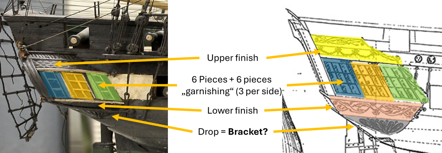
THAT is an interesting book - thanks for sharing! Decorative Figures on ships sterns and quarter galleries Here in pictures, how I right now understand the words in that bill: "one pair trusses for Stern [pair] Bracketts for Quarters" - this is one of the statements I am not sure about. "trusses" (I guess this is framework below the surface, to support structurally) for a pair of stern brackets for quarters. Where would wooden frame-work be needed? I do not see the need of any extra wooden support pieces for any brackets below the stern decoration in Old Ironsides - beside those lower finishings on the galleries. For those the wording "pair" would make sence. AND: a "bracket" in architecture is an often a very decorative element, supporting a wider structure onto a vertical "wall" - like a balcony or something comparable. So maybe this interpreation and naming of the elements makes sense? As stated: there IS a pair of brackets - which are these interesting and a bit strange brackets left and right of the window section (visible in the 1812 Isaac-Hull-Model) .. but why would those more "decorative" and most likely "symbolic" brackets - for which its just not clear what they do support? They are a bit too high for that decorative structual "bridge" of stars and eagle above the stern windows. They may be "intended" to support the upper bow - the one with the two ladies (Justice and Liberty?) and the strange elements in the top center of the stern decoration - just above the eagle. But why would THOSE need any "trusses". If that would be right, then the decorative "drob" below the planking of the galleries (and visible from the stern) may also be named "brackets" - ans this structure seemingly supports the galleries as a total element. Is there anything out there to support that interpretation of the elements of a Gallery?

-
She´s still a dangerous beast, isn´t she? 🤣 ... and still undefeated !
-
Having studied the one or other book - I have to notice: details of galleries internal structure is not very well documented in most of the books I have. Hull, Galion, Pumps, etc.. everything is described in details - but the inner structure, the internal pieces of a gallery, .. al that is rarely described in drawings and sketches. Even in Boudriots 74-gun ship book (Vol. 2 plate XVIII) it´s hard to identify details. And having also re-read my yesterdays post I need to apologize .. First of all: I did miss the difference between "Quarters" and "Gallery" .. Quarters being the rear side of the ship - while the Gallery of course refers to that structure beside and outside the hull at the rear end of the ships sides. So let´s restart with that approved bill and the description of what has been done by that Daniel Trains : "Billet Head, with figures" - clear: thats the decoration at the bow of the ship "Quarter Pieces with Bust" - that´s the outmost wood at the edge of the quarters to the galleries - in early days of Old Ironsides maybe decorated with figures (as described and still the blue circled heads in aboves picture of the Isaac-Hull-Models stern may be that busts the auther talks abaout. "upper and lower finishings for Gallery" - well here looking into my AotS books (and others) showed me, that here obviously are roof and the lower planking of the galeries are meant. This bill may describe the change from a previously ornamntal decorated hollow but flat surface to that shingle covered "roof" we see in the Issac-Hull-model and in the Ware Drawing. "one pair trusses for stern [pair] Bracketts for Quarters" - well this is not for the Galleries as I was thinking yesterday - its for the ships stern. Now here I need help: in the beautiful AotS book about HMS Bellona Brian Lavery shows on page 54 and 55 "brackets" as two decorating pieces on the rear side of the Gallery visible only from behind the ship - beside the blind (?) rear window of the gallery. Our Isaac Hull Model also shows "brackets" in that position - at least one per side between the quarters windows and that gallery back sides. Here are two "brackets" which are those purple marked "things" below the blue marked busts on left and right side. But: "Trusses" are usually structual pieces providing stability and strenght.. why would one need a special mechanical support for such a decoration? Is this really what that bills approval is describing? Wikipedia provides as explanation for a "bracket" an interesting alternative: Example Wikipdia provides: Even better: My wild guess: the "bracket" they talk about is that lowest final element below the galleries - also visible from the back ("quarters") - and is part of the structure "holding" the lower finishing in place. Fun fact: in some books this lowest end is called "drop", Boudroit describes this segment on Panel XVIII as "lower finish" .. I have to admit: my books either have no describtion or controversal description of that lower end of the galleries and other elements of the structure of a gallery. What do you think about that guess?? But there are still other elements: "Six pieces Quarter" - well .. what might be described here? Hm.. were do we find 6 elements on the Quarters? If my understanding is correct and "quarter" describes the back side of the ships hull - then there are only those 6 windows .. the posts in between the windows would be seven .. Did Train use the expression "pieces" for a total window-"panel" - maybe including the mullions? "six pieces of garnishing for front of galleries" .. that makes 3 per side - and its clear not the rear side but the front. Where do we find 3 elements per galleries front? If we´d assume that the windows are blind windows (with the expeption of a small opening within the center "window" - and if we do the same assumption as above: a "piece" may be more than one single post or mullion - we might identify that "garnishing" as the total "window"-"panel" with decoration which "simulates" those 3 window panes and the frames per side for them - including the decoration of the pieces in between them (Boudriout calls them "munions forming the framework" .. others describe them as Mullions .. again: my literature at least is not distinctive). That interpretation would allow to fit the numbers with the expressions used and the elements we see in the stern ... Is all that imporant? Naaa !! .. not really. I just like to have a certain understanding and aligning the known desciptions with what we see - it is just fun. And .. I believe some of the myths and mysteries of her previous design and shape can be sorted out by a more precise view into the existing information. Re-thinking the wording (like what´s a "bracket", how to understand the expression "piece") may help here. And: I would love to hear your expertise in this - as such an enterprise is always much better with teamwork and "swarm intelligence" ( o.k. - one may drop that actual global developments in many fields seem to imply: there is no such thing as a "swarm intelligence" - but at least there is a wider chance of finding the needed know-how amongst the audience here) does anyone of you have a better describition of how galleries are really done? the internal Structure of that thing? .. and descriptions fitting with above mentioned ones?
- 16 replies
-
- 1
-
-
- constitution
- revell
- (and 1 more)
-
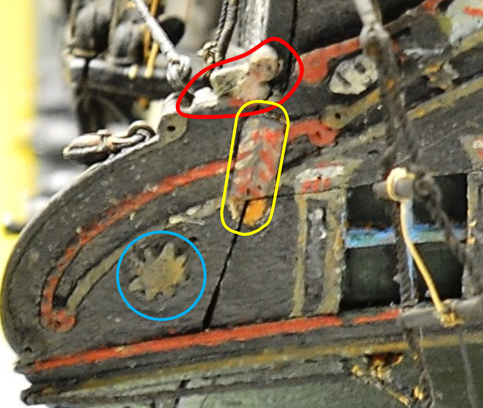
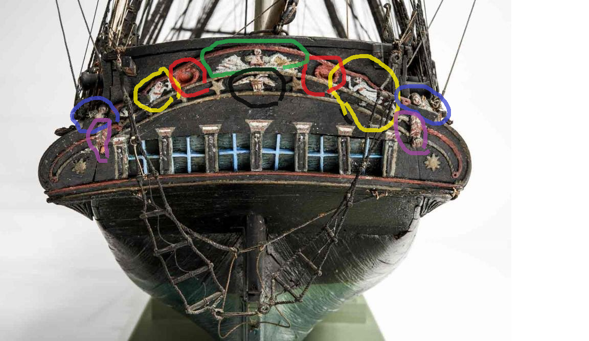
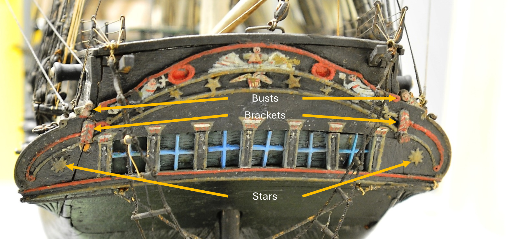
Gentlemen, Ladies, I need your help, please ! there is a description about the rework of decorations in 1808 .. This is from US Constitution Museum Blog and it refers again to M.V. Brewington. Shipcarvers of North America, M.V. Brewington, 126 I think I understand this: Carving a Billet Head, with figures which gives us the hint that the 1804 needed Billet Head (Hercules was lost to the US Frigate President - a collision of the two sister ships destroyed the original figure head - our strong popular hero holding the roll of papers with the Constitution high above the waves.. Also this makes sense to me: quarter pieces with Bust etc Since I think that the "bust" refers to that little heads on top of the quarter pieces visible in the Isaac-Hull-Model see here: ... the two little guys left and right in that blue circles on top of the quarter pieces .. see also here... I also get these two items: upper and lower finishings for Gallery I would think these are the upper and lower horizontal decoration rims of the Galleries windows - or what do you think "finishings" refers to? But what is meant with THIS here? one pair trusses for Stern [pair] Bracketts for Quarters What are trusses in this? And what are stern Bracketts for Quarters. Does anyone understand the structure of the timbers of a wooden ships gallery? The six pieces Quarters, six pieces of Garnishings for front of Gallery I would think are the stonger wooden frames in between the windows - including their decoration. Although I admit that the number 6 would mean that todays representation with 4 per side would either not be valid or the carver did find one per side still functionable enough. Here we see - as I think - 4 quarters in between and in front and behind the 3 windows. If I compare the actual design with whats presented in the Issac Hull model: I would think that the rear wooden quarter piece is quite small - maybe they were not count? But if my understanding would be correct, then in this representation the "six pieces of garnishing" does not fit - since if that would be just the decoration of that beams between the windows, we just see 2 per side - not 3 .. The two stars we discussed above already. Let me know if my interpretation is wrong pls.. And I would appreciate to read yours ..

-
Well ... reviewing the model kit itself in internet I found this statement: I guess I need to apologize - since the mentioned "1797" on the box most likely is only a reference to the frigates launch - while the kit itself may be a very accurate representation of the Lord-Restoring efforts. If you like the ship in those years ... I am looking forward following your steps - and if you like I can provide some information, myths and rumors I gathered the last years (2 decades by now - although with huge gaps on engagement) - mainly with a lot of advice and hints by so many kind and knowing modelers in this and in other model-ship-forums (a BIG, BIG THANK YOU from here !!) We all know that the ships earlier appearance is a mystery - and that a lot of ideas and interpretations are billowing like fog .. and its hard to see the real shape of things. So what are your sources so far? I would advocate for the choice of "Frigate Constitution" if I am to decide .. and while reading this I notice that my previous "U.S. Frigate Constitution" may have been as wrong as a "USS Constitution" for those years. I just recently saw an old newspaper asking for volunteers to hire onto the ship - headline "Frigate Constitution". .. no U.S. .. no U.S.S. of course..
- 233 replies
-
- 2
-
-
- Model Shipways
- constitution
- (and 5 more)
-
As I am very much interested in the ships 1803 appearance and did some research on the older design - I would like to hire and come abord for your trip! I am also curious about the quality of "the most accurate kit" - since what I see at the bow on the box´s pictures is for example not a Hercules figure head which should be there for the 1797 apprearance ... So how much do you plan to modify the kit? Most important in any way: have fun !
-
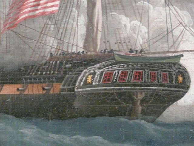
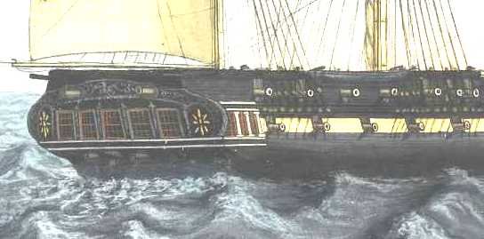
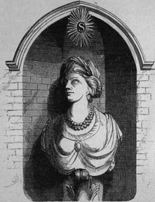
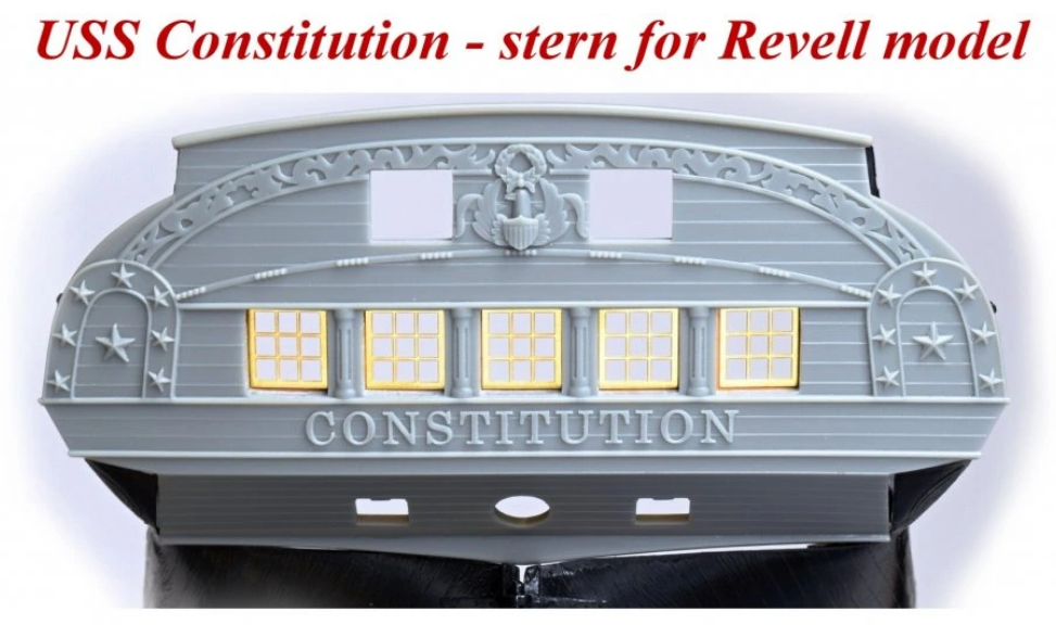
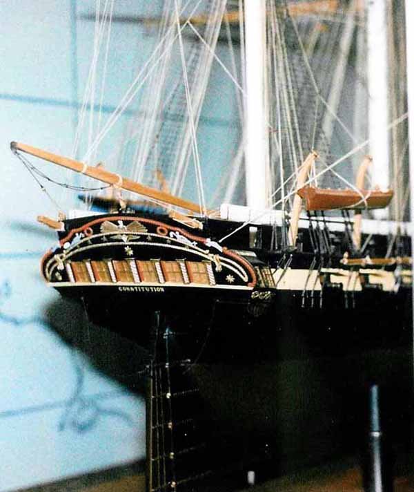
Thanks for that suggestion! It fits with comparable answers I got in other forums. If that´s the case - would then these extra steps be only on one side? Was the "official" gangway for VIPs only on one side of the ship? In a way it fits to the big frigates - being frequently flagships of a commodor´s squadrone, right? And that would explain, why this feature is so rarely seen in other frigates. We all know that "Admirals Port" on HMS Victory - being too a flagship. So two questions I have for you all: a) did you ever seen anything comparable on other ships? b) would this feature be only on one side? Was there a traditional "right" side of a ship for VIPs? Ahoooy there, what´s up, Doc? .. Evan, thanks for the kind words. Its fun and crazy how much one still can find although having studied this topic that much .. there is still that much information.. Maybe I have another interesting feature for your build: Did you finish your stern yet? I am chasing another detail. Revell offered us a stern which was designed by a Mr. Campbell for the other well known Mr. Chapelle - and this design is visible in that museums model in the Smithonian Museum in Washington D.C. (.. well I don´t know .. is it still visible there?). You can see - all the features we see in the Isaac-Hull Model for the 1812 design. Pls. note the two stars on the sterns back - on the galleries back side. Campbell based his design on the Isaac-Hull-Model - in PEM in Salem. Here too we see the 2 stars.. Interestingly: in the center just above is a marking - and I learned that here in former times there was another big start on that model. In nearly all representation of the 1812 - Guerrier-Battle Old Ironsides is represented with these 2 big stars on each back side of the gallery: Details in one of Felice Corné´s painting Here a detail done by George Ropes, Jr. - beautiful and huge stars! We also know, that the ship got 2 stars on her stern - added by John Rodgers in 1808 (not personally of course 😁) .. We know it due to a still existing bill: M.V. Brewington. Shipcarvers of North America, M.V. Brewington, 126 Now recently I stepped over an article dealing with the US Frigate Chesapeake - and the history of a model made from bones being in a museum in Hamburg, Germany. That article was written by a J. Huntington Lewis - HRNM Docent & Contributing Writer The title is Chesapeake, to the Bone In this artikel, the author mentioned his finding about 2 stars on the stern of USF Chesapeake - in a book from 1866. The American frigate had - as we know - been taken by the British HMS Shannon in one of the most bloody encounters in which the also famous (but unsuccessful) phrase "don´t give up the ship" was stated .. The ship stayed in British waters, until it was scrapped 1820. And some of its decoration found its ways into local buildings. This graphic shows one of the two stars from the frigates stern: Now .. - knowing that the 1813 lost frigate had two stars indicating the origine of the ship from U.S. - United States .. and - noticing that the 1812 US Frigate Constitution also got 2 stars on her stern .. and - seeing that those two stars are visible in almost any graphical reproduction in which the ships stern is visible .. I begin to wonder: why is only this feature of her decoration so prominent in all paintings and etchings? was this, because the two stars were a good indentifier for the public to recognize which is the American frigate? was US Frigate Constitution also marked as a ship belonging to the "U." "S." ? have those two stars being a "signiture" of the US ships in those days? HISMODEL is selling a stern, which can replace the - beautiful but doubtful Revell-represenation on the 1/96 kit. There are features I like about this representation. But there are features, which seem to be odd and wrong. Corné showed in non of his "Guerriere" paintings the ships name on the stern .. while it is visible in the 1804 Tripolis paintings - although the ship was very, very tiny in those battle scenes off North Africa. So I doubt that the ship had its name written in 1812. The two stars - typical 5-pointed-stars - seems to be plausible on first view.. But compared to the paintings .. and that USF Chesapeake stars it seems wrong. I believe that stern is more comparable to todays stern - just more decoration. But that anyhow fits with my thinking that the 5-windows here and todays stern with only 3 windows is in fact closer to each other than one may think. If you imagine the 2 outer windows of that 5-window pattern to be "fake-windows" .. blind windows which have been painted in 1812 and which are not painted and faked as windows later .. the rest of that proportion would fit pretty good, wouldn´t it? So this Hismodel-representation may have its value .. hm.. the price, though .. well.. What will you do Evan? @Force9 For my 1803-04 representation I anyhow have to chose a different approach. I guess I need to find a good way to represent much more decoration - and an open taffrail.
.thumb.jpg.ce304a2ce04caa62a8ad30afd821d7c3.jpg)


.jpg.68c2dc087e58fa6708ecec6fba893aad.jpg)