-
Posts
1,867 -
Joined
-
Last visited
Content Type
Profiles
Forums
Gallery
Events
Posts posted by Chuck Seiler
-
-
Pops,
I found they have 6's, 8's and 10's at bolt depot. You can order them individually or by the box. I will look into that option.
-
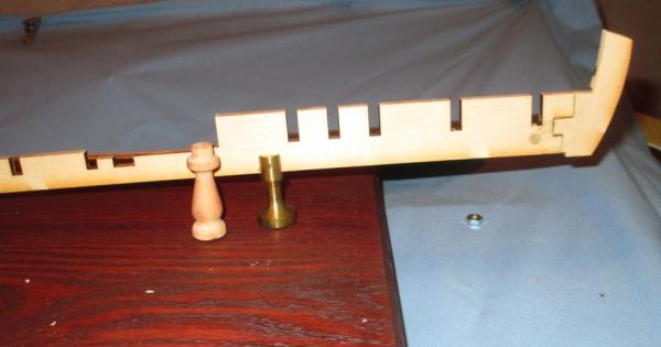
Two alternatives to mounting.
1. Use the pedestals I have and wood screw them directly into the keel. If that is done, both sides of the keel adjacent to the screw hole should be beefed up for support.
2. Use an existing brass pedestal. I had a spare Model Shipways 1 3/8" brass pedestal with 5/32" slot that worked okay. It is a little short for my tastes, but that is a personal preference. Perhaps ME has larger ones.
......or, hanger bolts.
-
Pops,
The ones pictured are a bit large, but it gives me some ideas to work with.
-
It is time to start, so let's start at the end. What did he say? Yeah, you heard me. <Oh dear, Seiler is into the magic mushrooms again.> Before I begin in earnest, I wanted to cover an area that I don't think is in the instructions and that I did not get to until almost last with my scratch PHILLY. Mounting the model. It is easier to worry about it now than later. so we will......
Good ol' Mike Lonnecker taught me to plan on how to mount your model early on and build accordingly. I MAY have done that with PHILLY 1, but obviously not very well. The support infrastructure I THOUGHT was there was not, so I ended up putting a couple big gobs of glue in the holes and gluing the model to the base for all eternity.
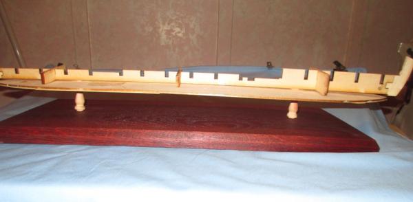
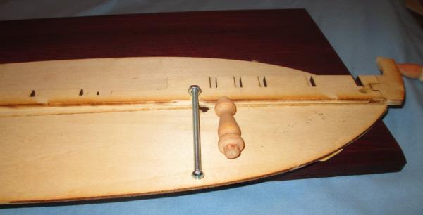
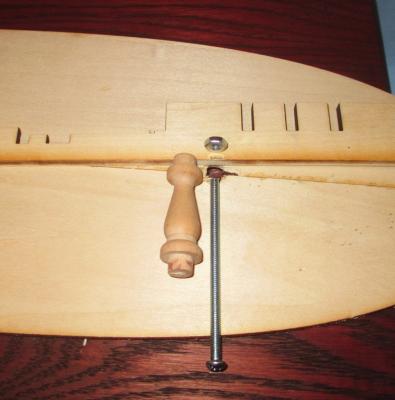
My plan is to use wooden pedestals like I did before, except slightly larger. I want to run a machine screw up the middle and screw it into a nut already mounted in the false keel. Mounting these nuts just forward of the forward cockpit and aft of the aft cockpit seems to me to be the most logical choice.
Here is how it will kind of look once mounted. As with Philly 1, I used a base board which will eventually be mounted to a larger board (which will be the base of the case).
Aft pedestal just aft of the cockpit.
Forward pedestal just forward of cockpit.
I would have preferred having the pedestals closer to the center but that would put them in the cockpits. I didn't think the cockpits were deep enough to make this work well. In retrospect, I may be wrong.
Once I figured out approximately where I wanted the pedestals, I drilled the appropriate holes in the bottom of the hull. (Hey!!! Your hull bottom pieces are already glued together so you are NOT starting at the end. Okay, you got me.)
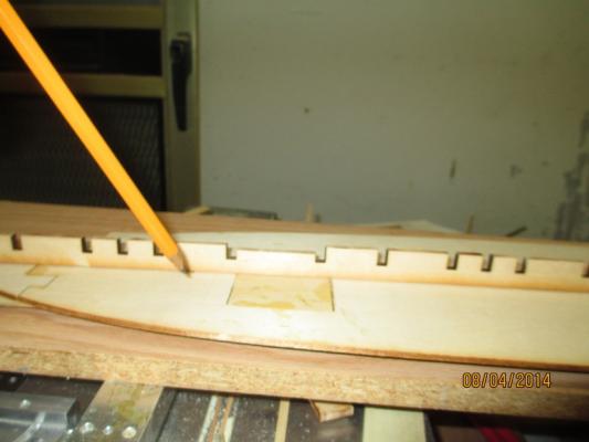
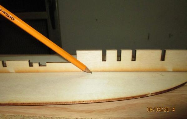
For me, it is easier to mark/cut the false keel based on the hole in the bottom that it would be to drill the hole based on the slot in the keel.
I also want to take this opportunity to drill the holes onto the base board I will be using. If I use the holes in the hull as a template, I should ensure the holes are lined up.
I will eventually have to drill a hole up the center of each pedestal. The screw will run up through the base, through the pedestal, through the 'floor' of the model and into a nut embedded in the false keel.
As it is, I will need to either cut away a small portion of the keel to accommodate the top of the pedestal, or sand the top of the pedestal to make it flush...probably the latter. I will then have to cut away a portion of the keel to allow me to embed the nut and leave room for the screw. I won't do this until I have the hole in the pedestal and can ensure everything lines up.
I would have preferred flathead screws, but Home depot didn't have them that long. I am investigating other sources.
- dgbot, jwvolz, bebopsteve and 2 others
-
 5
5
-
Yeah, I have had problems with the stem creep. I learned alot from BobF's Longboat build.
-
That's true, but the area to be planked is defined by the wales on top and garboard strake on bottom, not keel.
-
Shouldn't you wait until the garboard strake is in before you insert your battens?
-
3/16 sounds about right.
In reality, I doubt if ANYONE will see the center strip and almost nobody will actually see the underside planking. The ME instructions did not call for planking the underside (that I saw) nor is it addressed in Kurt's article. Some people may wonder "Then why plank it?". As I expressed to you seperately in an IM, I think planking the bottom is important because (1) Just because, ( b )To demonstrate that it really is the bottom of the boat and not a waterline model.
Hi Kurt!.
- Mike 41 and bebopsteve
-
 2
2
-
Steve,
My strip on the underside is as wide as the centerpiece/false keel, whatever that is. It is 3/64 thick, as are all the other planks. In reality, it would stick out a little prouder than the bottom planking, but not much-only scale inch or two. However, that makes it unstable when it sits on a flat surface, so I make it all the same.
-
Steve,
Looking good!
Rumor has it ME has PHILLY on sale for $119. Maybe we will get more builders. Sounds like a 'community build' project, eh?
- mtaylor and bebopsteve
-
 2
2
-
We shall be watching your build log as well.
-
I didn't know they had video back in 1776.

-
<Orchestral overture, waiting for the curtain to rise>
Getting ready to start the build, let me make a few points.
--Before starting the build in earnest, I strongly recommend checking the parts list and ensuring you have all parts before you begin. It is frustrating to get to a certain point and find you are missing something. Model Expo is very good at replacing missing parts. Likewise, review the instructions/plans to see what parts you are going to need first, find them on the parts sheet then mark the numbers on the actual parts wood sheet, preferably on the part itself. Kurt Van Dahm, in his “Ships in Scale” article, recommends marking ALL parts before starting.
--I will occasionally be referring to Kurt’s series of articles on the building of the PHILADELPHIA. For copyright reasons, I cannot reproduce the articles, but I can point out helpful hints (I hope) and make occasional smart@$$ comments (Hey Kurt, your Haas painting is backwards) without fear of reprisal. If you don’t already get “Ships in Scale” magazine and would like copies of this article, I believe they can be purchased directly from the magazine. The articles are quite informative.
--The glue that I normally use is a yellow wood glue, normally Titebond. White Elmer’s glue works well also. There have been raging discussions about the value of one glue over the other, which I will not get into here. I just find these glues to be the best overall. As Kurt points out, if you mess up, 70% isopropyl alcohol works well to get it apart. I will use other glues (CA or other) throughout the build if necessary. I sometimes use CA as a tack-weld to hold something until the glue dries. There will be other places where I am gluing metal to metal or metal to wood.
- bebopsteve and mtaylor
-
 2
2
-
Dave,
I thought you were going with the Popeye motif.
-
Mike,
Thanks. I saw...HMY FUBBS.
It looks like 3 of us are building PHILLY at 1:24 scale. I think you need to build WASHINGTON in that scale and we can field a whole fleet. :-)
-
-
The wale(s) served a couple structural functions. First, it helped hold the frames in places much like the hoop(s) of a barrel. In truth, there are alot of other things holding the frames in places, but that give you a basic idea. The other was to provide meat/support for the knees/ledges and other deck related structures. The strengths gained in the bow as you approach the stem more than make up for the weaknesses incurred by the slight decrease in thickness.
-
...and here we all are!!! Welcome to the build Steve. Hopefully a bunch of my followers will cross over.
-
Dave,
I think you will find ALOT of crazy people in this forum. First construction should be posted this week. Promise!.
- bebopsteve, dgbot and mtaylor
-
 3
3
-
Dave,
Thanks for the kind words. I will be wrapping this Philly up some time soon. I have basically been languishing and working on other projects. Philly 2 will be starting up on the kit side soon. I noticed you have found that site.
Steve Y is starting up a Philly kit as well, so hopefully you will be able to watch them come together, side by side (huh?).
-
-
I am wondering if the 'typical' 30 hour assembly time is for the machine itself or an average 7.87 x 7.87 x 7.87 inch piece. I have heard that the process takes awhile.
-
-
Hi Tim. Welcome aboard.
Mark, I meant to say spaces before and after the dash in my Build Log Title. The edit button lets you edit the individual post, but I don't know of a way to edit the header/title. I was re-reading Dan Vadas' notes on the naming convention and it appears I left out the spaces.
It is in the kit section. ....already started....post #14.


Continental Gunboat PHILADELPHIA by Chuck Seiler - Model Shipways - 1:24 Scale - Enhanced
in - Kit build logs for subjects built from 1751 - 1800
Posted
Thanks Joe. You can kind of get away with waiting until the last minute when you have a ship with traditional keel. This flat bottom makes that alot harder.