
Supplies of the Ship Modeler's Handbook are running out. Get your copy NOW before they are gone! Click on photo to order.
×

Cuda1949
-
Posts
194 -
Joined
-
Last visited
Reputation Activity
-

 Cuda1949 reacted to smarra in US Brig Syren by smarra - Model Shipways - 1:64 - First wooden ship build
The bulkheads are faired and all but three bulkheads are glued in place.
Not sure where I saw on this site about the lego blocks for squaring the bulkheads, but it has worked out perfectly so far.
The keel is still pretty much square. I'll add balsa filler blocks next to keep it that way.
-
Cuda1949 reacted to smarra in US Brig Syren by smarra - Model Shipways - 1:64 - First wooden ship build
Finished the first chapter in the instructions.
-
Cuda1949 reacted to jdbondy in Pride of Baltimore II by jdbondy - FINISHED - Model Shipways - 1:64 scale
This picture shows installation of the sheets for the fore topsail yards. These lines for the upper yard run to the blocks at the mastcap of the mainmast, above the radar dome, then down to the deck.
The sheets for the lower yard arise from the mainmast shrouds, running to blocks on the lower yard, then back to a pennant that is also attached to the mainmast shrouds. Then down to the deck.
This pennant is about ½” in length. It took a lot of wraps of fly tying line to make it.
Here is one of the rigs for securing the boom when at anchor or tied up at the dock.
It ties off at a solitary pin on the deck rail.
Here I am cleaning up the lazy jacks. It was difficult to work on one without over-tightening it and making the others suddenly look slack.
Cleaned up pretty well, though.
The mainsheet is of course quite long since the sheet runs through an extensive series of blocks, including a triple block between the (missing) ship’s wheel.
The navigation lights are located on boards that are secured to the shrouds. The boards were manufactured from thin sheets of pearwood. Painting the lantern was a very delicate matter!
Starting to work on the flags. The flag on Pride 2 is a 15-star flag, which as I recall indicates the number of states at the time of the War of 1812 or thereabouts. The flag was drawn using Paint, originally in a rectilinear manner. Then the skew function was used to skew the flag as you see it here. It helps to create a more naturally drooped final product. (Credit for the flag making techniques shown here belongs to Dan Pariser.)
The Maryland flag was also drawn using Paint, and skewed in the same way. This one is printed onto fine cotton cloth, and before cutting it free, the edges were treated with an anti-fraying treatment.
This was a first try for the pennant, printed on paper or silkspan. However, it didn’t handle crinkling well, as extensive cracking developed that you can faintly see here.
A small amount of extra fabric was left on one short edge to accommodate the flag halyard.
For each flag and pennant, the image was printed onto each side of the cloth, requiring mirror images of each flag and pennant. Pieces of fabric were taped over a paper onto which the flag had been printed, then run through the printer for the first side. Then each piece of fabric was flipped over and carefully taped to overlie its mirror image, and run through the printer again. Multiple attempts were done and the best was selected.
The flag halyard cleats were very small. This image shows how much reduction of one of my stock cleats had to be done to achieve a scale size.
These were then lashed to their respective shrouds with fly tying line.
Ready for my closeup, Mr. DeMille...
A yellow clamp at the level of the desktop secures the two halyards for the flag and the pennant at the mastheads.
The Maryland flag did not droop quite as much as I would like.
But I got a better result with the US flag. Each of these was crinkled by wetting with a spray of water, then crinkling it up and allowing it to dry. The lowest corner of the US flag was put under some tension to help it droop.
This flag is rigged essentially on the boom topping lift.
The finished model, with flags in place.
A journey of more than 20 years is now at an end. I didn’t realize that there is a nice little history behind me of my other ship models! This one is by far the most complex, and the most satisfying.
I moved it into the corner while awaiting the arrival of the display case kit. On the wall behind it is a model of Cuilaun, built by Rob Eddy of Camden, Maine. On the other wall is an antique map of the island of Martinique.
My shop looks so clean at this time! I have mentioned it before, but my main workbench is actually a motorized sit-stand desk that has been essential.
After a lengthy delay, the display case was ready. My neighbor and I VERY carefully put it in place while my wife took pictures.
The glass case is actually a little too large for the bookshelves it is on, so I cut a piece of plywood for the case to rest on.
My wife spontaneously said that it needs to be more prominently displayed than in the corner of my shop, which I was very pleased to hear! So initially it went onto the sofa table. But it seemed sort of vulnerable there.
So instead, we cleared off this piece of furniture that was bought to support an antique mirror that came from France.
And now both sides of the model are on clear display!
-
Cuda1949 reacted to jdbondy in Pride of Baltimore II by jdbondy - FINISHED - Model Shipways - 1:64 scale
Since I bought the Pride 2 kit in 1995, many times have I looked at the bowsprit netting on the plans sheet and wondered how in the world I would go about doing that. Recently, though, it became apparent that I was at a point where I could start working on it. The bowsprit and dolphin striker had been installed, and the guys were in place. I had not yet started installing either mast, but had been working on the sails. I realized that trying to install bowsprit netting after having put in all the forestays would be difficult, as the forestays travel to the tip of the bowsprit and then travel back to the bow underneath the bowsprit. Those would obstruct the area of the netting.
A year or so earlier, I had tried assembling a bowsprit net off the ship, using a jig that I built out of scrap. The blocks at the top and bottom have grooves cut in them.
Using some coarse leftover line, I took about 10 strands and ran them between the blocks. The strands traveled in a zigzag pattern essentially parallel to each other, without actually crossing each other (like chain link fence). Fine line was used to attach the lines to each other. T-pins maintained the shape of the net at the edges.
This wasn’t very satisfying, because the netting would have to have an overall triangular shape, with an apex and then widening as it approached the bow.
Another jig was built that had more of a Christmas tree appearance. Work with that jig produced a net like is seen in the bottom of the next photo. (The net in the top of the photo is the final product that resulted from all these first tries.)
Work with the jigs helped me realize that the netting would have to be a true netting, meaning that the strands of the netting would have to cross one another, instead of abutting one another where they were attached to each other with the finer thread. And the fibers would have to weave above and below one another to create a more stable structure.
The question really became: is it possible to build a net off the model and then install it? Or is it necessary to build it in place on the model? Of course, the ultimate solution would be a combination of both.
On the real ship, the netting does not attach directly to the bowsprit guys. The netting attaches to finer line that is intermittently seized to the guys. The next photo shows a 0.004” line being seized to the guy using very fine fly tying thread (Veevus 16/0).
And a close-up:
After attaching this line to each guy, a test run was made by running lines through these gaps on the guy and weaving an initial in situ bowsprit netting.
It was clear that something would have to be done where the netting and the guys meet. Simply weaving the fibers through the gaps on the guys causes the line to very gently curve up to where it meets the guy. In reality, these parts of the netting need to look like sharp corners.
It was also a puzzle what to do at the fore edge of the netting, where the fibers all came together. They could be gathered into two common points, but the fibers look too crowded and less net-like.
In order to get the edges of the netting to be more orderly, and in order to make the fibers sit neatly, they were waxed. Plain beeswax by itself is not very pleasant, as it leaves a whitish residue that is visible on the line, especially if it is worked too much. But a piece of beeswax that has been colored with Transtint black dye can be used to coat the lines with no visible residue. This took some experimentation in order to get the granular appearance of the beeswax on the line to disappear, which typically involved heating the line by pulling it through tightly pinched fingertips and letting friction melt those waxy deposits into the fibers. They became much more orderly after that.
So instead, the netting was begun using a single line that ran athwartships at the fore edge of the netting, and five lines were seized to that line. That gave a total of 10 fibers traveling aft that could be used to weave a bowsprit net.
Next step was to install some loops along each guy that could be used as temporary attachment points for the netting, enabling me to create a netting in place while being able to remove it once I was happy with its shape. In order to get the netting to attach more realistically to these temporary loops, it would be necessary to seize the fiber of the netting as it came up to each of the attachment points on the guys, so they would not gently curve into the guys but would come to a focal attachment point.
The guys looked pretty ugly after installation of the temporary loops, which were created with a generic, fuzzy sewing line. Fortunately that made it easier to identify which lines needed to be snipped later on, and which should be left alone.
Now it was possible to take the 10 strands attached to the one line and set it at the tip of the bowsprit and guys, and begin weaving the netting. I pretty much weaved the entire netting, leaving the aft most edge open. Then it was time to go back and seize each fiber of the netting where it met the guy. The first photo shows the netting fully weaved, then the second photo shows the seizings going on.
There are seizings on the first 5 points on the left side of the photo, and the points to the right remain unseized. Seizing usually involves 5 or 6 wraps, with the bitter end tucking into a loop under the wraps. These seizings were nothing more than a series of overhand knots, with the tails of the overhand knots wrapping around the line and a second overhand knot tied next to the first. The overhand knot was then finished with a square knot. While doing the seizing, it was necessary to include enough slack in the fibers so that the netting would droop below the bowsprit. Once the seizing was added to a particular point, it was no longer possible to adjust the amount of slack in that particular fiber, so this was a key step. Seizings also had to be added symmetrically, so that one side of the netting would not have more slack than the other.
To give the netting more stability, temporary knots were tied in the netting in the centerline. Initially the idea was that at each point where the fibers of the netting crossed, a knot would be used to secure the two lines against each other. Here is a picture with nearly all the seizings in place. The temporary knots in the centerline are faintly visible under the bowsprit.
On the real ship, the netting looks like this:
I ran out of attachment points for the ends of the fibers at the aft end of the netting. You run out of room when there is the bowsprit cap and the dolphin striker protruding down from the bowsprit. So at the aft end of the netting, two of the fibers attach to the same point along the guys. This would turn out to be a temporary arrangement.
A row of permanent knots was tied at the edge of the netting immediately inboard of the bowsprit guys and the seizings, in order to give the netting more substance for when it would be removed.
At this point I was happy enough with the size of the netting overall that I created loops in the aft ends of each of the 10 fibers. The tails were left long, just in case. Once that was done, the netting could be cut off of the model. In the following picture, the temporary knots are visible along the centerline of the netting. These were replaced with permanent knots using Veevus fly tying thread. The permanent knots at the edge of the netting are visible, just inboard of the seizings.
At this point, the netting was adjusted to get as much symmetry as possible. Two additional rows of permanent knots were added, between the row of knots in the midline and the knots at the edge. I decided not to tie knots at every single crossing point, because it seemed like the net was holding together fine without tying that many knots. Once I was happy with the overall pattern, I used Flexament to secure the knots, and the tails were cut off as close as I dared. Here is the final product. Ahh, that looks so much better…
It was time to reinstall the netting on the model. I secured it as I had before, in terms of the spacing along each bowsprit guy, but now that all those knots had been added at all those crossing points, the netting no longer hung down beneath the bowsprit. It was in fact very flat, ruining the overall effect. The culprit was too much fore-and-aft tension on the netting, but this was easily fixed by changing the spacing of the attachment points of the netting. Now the netting did not extend as far aft underneath the bowsprit, but a nice consequence of this was that things were no longer crowded up in the area of the dolphin striker and bowsprit cap. This picture shows the netting attached at several points, with most of the attachment points still loose.
From here it was a matter of getting all of the points attached and trimming away the excess line. At the aft end of the netting, there were two spare lines that were meant to terminate near the bowsprit cap, but they would no longer reach. I therefore attached these ends to another one of the netting lines. A compromise that you can see in the following picture:
All points have been attached, and the only remaining task was to trim away the excess, leaving you with this:
The droop of the netting is actually too much, and I don’t like how the netting gathers up about 2/3 of the way back. But otherwise I am happy with how it turned out. And I can put this task behind me! As long as I keep the bowsprit protected from inadvertent injury…
This was an incredibly satisfying step to complete, as I had no resources to work with except the specifications on the plans and the images of the real ship. Many different steps required many different trials and errors to reach the final product.
-
Cuda1949 reacted to jdbondy in Pride of Baltimore II by jdbondy - FINISHED - Model Shipways - 1:64 scale
OK, I need to get rolling along. I am posting this in May 2018, and I am only up to mid 2016 in my descriptions. Plus the model is almost entirely finished, and I am anxious to get up to speed on how things actually look.
Next topic is to start assembling the fore topmast to the foremast. I decided not to permanently glue the topmast to the foremast, in case for some reason it ever needed to be disassembled. Like in a restoration. God I hope I never have to do that. Anyway, shrouds with deadeyes were installed on the topmast, and deadeyes stropped with wire had to be installed in the trestletrees. The wire installation was a tricky assembly because the stropping had to run through the wood of the trestletrees, then come down and form a loop for another wire to attach to. Then that wire extended down to the mast, where a black band representing an iron hoop had eyebolts sticking out of it. And with all this, a sense of scale had to be preserved. No painting of the wire was needed since I had a supply of black wire in various sizes.
Sitting in front of the trestletrees and wires is one of the shrouds, which is Morope line that has been served with fine fly-tying thread.
The deadeyes were then threaded, and the ends of the lanyards were seized to one of the other strands of the lanyards using a “West country whipping”.
This is one of the 10 (paired) blocks installed on the fore topmast that are used for the control lines of the fore topsail yard. Each pair of blocks were attached to eyebolts, with pendants of increasing length depending on how high they were attached to the topmast.
They kind of look like bugs.
And here are the blocks attached to the fore topmast. The pair of blocks further up are seized directly to the mast and are not attached via eyebolts.
In the course of rigging the foremast and fore topmast, I suddenly realized I had installed the topmast shrouds so that they ended too high on the topmast, extending nearly to the very top of the topmast. In the photo below, they should end at the level of the highest pair of blocks seized to the topmast.
I was concerned that this meant I would have to completely cut the shrouds and start over again. However, it was possible to physically loosen the seizings holding the shrouds near the top of the topmast, then cut the seizings away. The shrouds were then slid down below the top pair of blocks.
New seizings were applied using 6/0 Unithread fly tying thread, and secured using Flexament.
Now it was just a matter of taking up the slack at the level of the four deadeyes by the trestletrees. I took advantage of the opportunity to re-do how the lanyards were rigged. They previously were tied off using a West country whipping that joined the end of the lanyard to one of the other strands.
The picture above shows one deadeye pair (the lower pair) with the older rigging arrangement, and the upper deadeye pair with the lanyard wrapped twice around the shroud where it is seized to the deadeye. The lanyard then comes back down and is seized in parallel with one of the other lanyard strands. This more accurately reflects the reality on the actual ship:
I was left with two deadeye pairs that were spaced wider than the other two. This was because I prematurely cut two of the shrouds before making sure I was happy with the overall length. To fix that would require re-doing the shroud completely. I figure that this model is going to serve as a living example of how to gradually improve on how you are doing things.
There, that’s better. Both lanyards are now rigged more accurately.
I also realized at this point that the 5 pairs of blocks I had so carefully attached to the topmast using eyebolts needed to be moved off the topmast and attached to the shrouds. Here, the top pair of blocks has been detached and stropped to the shroud. To give each block a shelf to attach to, I first tied an overhand knot onto the shroud that would keep the block from sliding downward. I then seized a pendant to the shroud with several loops of fly tying line that was run through the loop left behind after the pendant was separated from its eyebolt. In this way, there wasn’t a need to redo each of the pendants that the blocks were attached to.
I don’t have close-up photos of the final product after all the shrouds had been re-reeved and the blocks stropped to the shrouds.
Putting ratlines on the shrouds seems like a simple enough idea before you start. Of course, which size line to use? Morope vs Syren line? How to secure it to the shroud? Actually, the biggest problem was how to take line that wants to do what it wants to do, and convince it to drape downward like ratlines should do. Especially when dealing in fine line like 0.004” or 0.006” Morope. Then there is the matter of making the clove hitches behave. They want to spring back open no matter how tightly you pull them closed.
A lot of these problems were overcome with beeswax. Beeswax helped to stiffen the line so that it would take the desired draping shape. It also helped to close up the clove hitch knots and get them to stay closed. But it also gives black line a visible coat of thick grainy buildup that is unattractive. The solution there was to take a chunk of beeswax and dye it black with Transtint dye. Doing this actually made the shrouds to look thicker and more realistic. The best ratline in the picture above is the middle one, appropriate looking scale while the line looks smoother than the ratlines on the left that look more bumpy in appearance. The ratlines on the right were done with thicker line, and with less care to make sure that excess wax had been removed from the line.
This is a look at the finished topmast shrouds. The foresail and fore gaff have been temporarily attached to the foremast. In the upper left hand corner of the picture you can very faintly see the pendants and 5 paired blocks now attached to the shrouds.
Next up: Sailmaking and bending sails to yards!
-
Cuda1949 reacted to jdbondy in Pride of Baltimore II by jdbondy - FINISHED - Model Shipways - 1:64 scale
This is a side topic to the builder’s log. In fact, I may have posted this series already to the forum. When working on the bowsprit rigging, I found myself looking for a better way to seize a deadeye within standing rigging such as the bowsprit guys. For the guys, I used 0.010” Morope served with fly-tying line, which gives a very smooth look to the final product.
Initially, I simply wrapped the served line around a deadeye and then applied a long seizing, then cut off the stub of the served line. This gives a very shelf-like appearance to the seizing. I felt that kind of appearance might be ok for the shrouds, but for the bowsprit guys I wanted a more tapered appearance.
Usually, when I do a seizing, it is the kind that involves 6-8 wraps around a loop, then thread the line through the loop, then pull the loop closed, etc. etc. However, I found that when I tried to apply that kind of seizing to line that has been served, there is too much friction between the seizing and the serving to allow you to slide the seizing along the line.
So instead, I simply created a long seizing that would not have to be moved, by using multiple consecutive overhand knots on alternating sides of the served line. I learned later that this is called a “West Country Whipping”. That is what is depicted in the photo above. The photo also shows that the seizing (whipping) covers the area where the shroud stub is cut off, with an abrupt change in the caliber of the whipped segment.
In order to give a more tapered look, here is what I did:
Start whipping around both ends of the served line.
Cut the end of the served line that will be discarded, allowing the serving to unravel and allowing the underlying Morope to separate into its 3 separate strands.
Let the Morope unravel all the way up to the last wrap of the seizing.
Snip one of the 3 strands, then continue the seizing.
Snip another of the strands, then continue seizing until you nearly reach the desired length of the seizing. Then a few more wraps to finish it off.
A nice, tapered deadeye seizing that makes the bowsprit standing rigging look a lot cleaner.
Like I said, I don’t plan on using this technique for the mast shrouds.
-
Cuda1949 reacted to jdbondy in Pride of Baltimore II by jdbondy - FINISHED - Model Shipways - 1:64 scale
So it's currently April 2018. The following pictures show the status of the deck as of October 2015.
The hinges on the deck boxes are small pieces of black decal cut into the shape of hinges. They bridge a little linear divot that was essentially scraped out of the wood using a graver-type tool.
The anchor rope and chain have been installed.
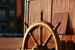
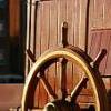
The ship's wheel was a part provided by the kit. I wasn't about to try to build my own.
The cannon are rigged in place.
-
Cuda1949 reacted to jdbondy in Pride of Baltimore II by jdbondy - FINISHED - Model Shipways - 1:64 scale
A long time earlier, I am not sure when, I tapered the dowels I would use for all the spars to their proper dimensions. This was done by hand, well before I ever had a lathe, using coarse sandpaper and elbow grease. Now, though, it’s time to work on the base of the masts where they take on an octagonal configuration, and the mast tops where they take on a square configuration. I used the pieces of wood above to serve as a groove to hold the mast steady while making shallow cuts into the base, then I used a file to create four flat faces.
I did the same for the mast tops.
These areas at the bases of the masts were then built up with pieces of flat wood to increase the cross sectional size of the flat faces.
The protruding corners were then carefully shaved off with a razor blade to yield an octagonal cross section. Do I have a picture of the finished product? Of course not! The octagonal portion was painted a cream color that matched the color of the inside of the bulwarks, and the rest of the mast was stained and coated with topcoat.
A picture of all the various spars on their places in the plans.
The bowsprit was painted cream for the inboard portion, then the outboard portion was painted black. The metal rings to which the hearts are attached are already installed.
Tenons were cut in the mast tops as well as the tip of the bowsprit.
The bowsprit is now in place, with its base inserting into the Samson post.
This is a picture of the deadeyes that are installed on the outboard surface of the bow. They rig to the standing rigging such as the forestays for the foremast and the bowsprit guys. Trial and error was again involved in figuring out how long of a segment of wire I needed to properly strop each deadeye. But it’s pretty satisfying work. A segment of thick wire is threaded through the loops of the stropping, and the end is peened to keep it in place.
How to start the bowsprit gammoning? Here is how I did it.
These are flat strips of brass that will be used for the gammoning irons. Holes have been drilled for wires that will pin the two lower plates to the stem. Harder to see are the holes that have been drilled to accommodate very small bolts that will join the lower plates to the single upper plate.
Thanks to Scale Hardware for manufacturing such exquisite small bolts and nuts that were a perfect fit! They even had a little wrench to hold the incredibly small nut as you thread it onto the bolt.
The yards have been stained, and the central part and the tips have been painted black. Metal bands have been placed on each; they currently have a coating of primer on them but will also be painted black.
This picture reminds me that I didn’t do a good job of documenting the process of building the trestletrees for the foremast or mainmast.
This part has turned out ok; the lanyard is threaded around several times and then is seized to itself with the smallest thread I had prior to discovering fly-tying line.
I was unhappy with how this turned out. The bobstay is composed of a line that threads through the stem and is doubled up on itself as it travels from the stem to the bowsprit. This doubled line is shown on the plans as having seizings along its length. These seizings look very rough and stubbly. I will come up with a better plan for this area on a subsequent post.
-
Cuda1949 reacted to jdbondy in Pride of Baltimore II by jdbondy - FINISHED - Model Shipways - 1:64 scale
Next up are the various pin rails that are set up around the base of each mast. These are the pin rails just forward of the foremast, which handle the fore topsail control lines. This is more pearwood. The pins themselves are segments of 0.014” wire.
I was playing with various finishes that I had handy at the time; sadly, all my Floquil glazes and flat finishes have now congealed and are no longer useable. I am back to using Testors Dullcote lacquer for jobs like this.
This apparatus surrounds the base of the main mast and is made of pearwood.
Here it is all assembled, and the chamfers have been added. Small bits of brass sheet have been applied to the top of each post.
There is a small windlass along the forward edge of the mainmast pin rail. It was painted white with a touch of rust to emulate the appearance of the real thing:
These are parts of the rail that sits just aft of the foremast.
It also has a mini-windlass attached to it.
Here is the area of the foremast with its pinrails installed.
And the pinrail at the base of the mainmast.
Time to work on the four cannon. The sleds are made with pre-cut parts from the kit. The cannon were also provided and required cleanup prior to blackening them. The quoins are the wedges under the back end of the cannon that adjust its tilt. Those were handmade and stained up.
An image of the real thing gives you an idea of the rigging used to secure the cannon. A very large line runs from the cascabel at the butt of the cannon to rings at the bulwarks. A smaller line is used to rig the blocks on either side of the cannon sled.
This took some trial and error. How do I take a pretty thick line and get it attached to these small eyebolts on the bulwarks? I suppose a purist would undo the weave of the line and create an eye for a hook.
Too much work for me. I applied some CA to the end of the line, then created an S-hook that could be stuck through the strands where the CA began to peter out. Where to do that on the opposite end of the line, though?
After inserting one hook, I assembled the rig with the one hook attached to its eyebolt, tied it to the cascabel, and ran the other end up to the area of the eyebolt. I marked that spot with marker and inserted a hook there, then applied CA beyond that point to solidify the line. The excess was then trimmed.
This is an image taken before the excess is trimmed away (left side of the cannon). Double sided tape is being used to temporarily secure the cannon to make rigging easier.
Now things are trimmed up.
These are 2 mm blocks that have been secured with 0.004” line. One set of blocks is rigged to the ring on the side of the sled. The other set of blocks will be rigged to eyebolts on the bulwarks. I don’t remember anywhere else on the model where I used such small line.
The line is rigged through the blocks and then tied off at the back wheels of the sled.
Now I just have to do that 3 more times. After doing this, small amounts of glue were used to secure the back wheels to the surface of the deck.
Through Billing, I was able to find a bell of reasonable scale to install on the aft cabintop. My soldering is getting better!
The fore topgallant sail is stowed under the port rail. I wrapped a portion of “sailcloth” (a fine Egyptian cotton fabric) around the spar and wrapped it with ties. The spar is then secured using small hooks installed on the rail and on the bulwarks.
I am slowly getting caught up to real time! These steps were done in 2013, and it is now January 2018.
-
Cuda1949 reacted to jdbondy in Pride of Baltimore II by jdbondy - FINISHED - Model Shipways - 1:64 scale
So here’s the problem with this after-the-fact blogging. I created replacement life rings to replace these horrible looking Britannia rings using pearwood, but since this was done in September 2012 and now it’s July 2017, I can’t really remember how I even got to this point! I don’t remember if I had purchased the Sherline lathe already, or if I just improvised with the Dremel. The inner edges of the donuts are clearly not concentric with the central holes. Obviously, the pieces had to be pared down in thickness as well as having the inner and outer edges beveled off. However I did it, here’s what it came to look like:
The pieces are being primed and then painted with CN orange. They turned out very clean!
The white bands were cut from index card stock, and enough of a space was left for white thread to be run within the white bands. A much better look than painting the Britannia fittings.
Next problem: A long time ago, I fabricated the deck furniture associated with the hatch just aft of the foremast. I had built coamings into the deck to accommodate this piece of furniture. Problem was, as I examined the dimensions of the furniture on the plans, I realized that I had built the furniture piece to accommodate the shape and size of the coamings I had installed. And I had installed the coamings so that their OUTER edges corresponded to the size that the furniture needed to be. So when I built the furniture, it was significantly too small. That meant that not only did I need to build a new hatch, I needed to remove the old coamings and make them larger.
The new furniture is taking shape on the left, and the old furniture is to the right of the coamings.
The old coamings have been removed.
Fortunately, this redo meant that I could use pearwood instead of stained basswood, improving the look of the grain of the stained surfaces of the hatch. Using flat topcoat, the pearwood surfaces are made to look very similar to the other stained surfaces of the adjacent lockers and hatch, but with much tighter grain that gives it a much more in-scale appearance.
I have noticed that on other peoples’ build logs for the Pride 2, there has been discussion about what to do for hinges for the fire lockers. My solution was to essentially grave a line that simulates the seam between the hatch and the rest of the locker lid. For the hinges, I printed areas of black onto decal sheets, then cut very small triangles from the black decal sheet. These were then soaked and applied to give the impression of dark hinges.
That's a good stopping point for now, I think...
-
Cuda1949 reacted to jdbondy in Pride of Baltimore II by jdbondy - FINISHED - Model Shipways - 1:64 scale
Time to get back to the big boat.
According to the pictures I have taken and saved, the next thing to get my attention was the display base for the model. A long time ago I had purchased pedestals to mount the model on, while the kit shows the model mounted on building ways. I purchased a piece of red oak from the local Rockler, with a plan to “ebonize” it according to an article I had seen in the Nautical Research Journal.
The piece of wood had to be heavily sanded to eliminate cut marks on it from a thickness planer. I also borrowed a router from a friend to cut out the molding on the edge. Good practice for my general wood working techniques. After sanding, the base was filled with Wunderfil, re-sanded, re-filled, and…you get the idea.
Be sure to wear gloves when putting on black Transtint dye! The stand I am working on bears permanent black marks on it from this process.
The grain really pops out while the wood is wet from the stain. Fortunately that becomes less conspicuous once the wood dries.
It was by this time that I had found a source for boxwood and pearwood. The pieces above are straight grain pearwood that were cut from a piece I obtained from the Gilmer wood company in the Pacific Northwest. I believe others on this forum have mentioned this source before. These pictures of such nicely cut strips of pear also remind me that it was at this time that I obtained a Byrnes table saw, and a thickness planer too! Wow, not even Christmas.
The pearwood strips were attached to the base with small pegs embedded in the pearwood, with corresponding holes drilled in the base board. Pure trial and error was involved in shimming the top surface of each piece so that the keel would sit squarely on each support. Pegs were put in the top of two of the pearwood pieces to provide attachment points for the hull.
Work on the hull itself includes placement of the chain wales, crafted according to the plan sheet. Notches are cut out of the edge for the chainplates, and a strip of wood will be put in place over them once the chainplates are in place. Pin rails have been placed on the port and starboard sides, and a pin rail is also in place at the bow (at the very edge of the picture).
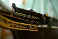
I know, this red lettering looks terrible. It’s made of transfer letters obtained at a model railroad store. Fortunately, they sanded off very easily and I simply repainted the surface with another coat of yellow after doing so. The lettering above it is carved into the piece of basswood that replaced the planked portion that I stripped off. The carving was done at my dentist’s office; he kindly offered me the use of one of his high speed drills with appropriate cutters. The carved out areas were filled with gold paint and the excess was sanded off, then glaze painted over the whole thing.
This is what the real thing looks like. Lucky for me, there is a black strip of wood separating the wood varnished area from the yellow strip, so I used that to cover up the gaps at the edges of my transom.
I wish I had felt confident enough about my carving to have added the pointy bits at the edge of the letters. Hey, at least I was able to learn what those pointy bits are called: serifs. Now it makes sense when I use that “sans serif” font in Microsoft Word!
The Baltimore Maryland lettering was redone using decals that I printed myself. I was able to figure out how to type text along a curved line in MS Word, to get the arc I needed. Then I had to learn how to use a color printer and decal printing paper to generate the decals I needed. That is not a terribly reliable process when one is using a bottom-of-the-line color printer. And I found that if you go to a print shop and try to print to decal paper, they generally don’t like it because decal paper can gum up their printers. Now, this is a few years back, so things may have changed since then.
So here is the hull, awaiting reinstallation of the re-done transom and its associated knees. The model is on a wood workers bench that I bought from Grizzly. And faintly in the background is the other big toy that arrived in this time frame: a height-adjustable work bench. We use these a lot at my various places of work, to take the load off our backs and keep us from sitting the entire day. Truly a luxury, because generally they aren’t cheap. More recently, I think I have seen that some members of the forum have been able to find less expensive versions through Ikea. I hope that’s true, because this hobby isn’t forgiving on our backs and necks. Anything we can do to help those matters is worth the effort. Especially when it comes time for doing rigging!
I have been working on the model for about 4 hours today, and it’s time to take a break before I break something. Figured I would come back to my retrospective build log. The photographic record indicates that it was time to make propeller shafts and brackets. The prop shafts were easy; it was the fabrication of the brackets that was difficult just to think about. I could easily picture how long the legs of the brackets would need to be, but it was difficult to get a sense of where they would sit on the hull, and how in the world to make the ends of the brackets rest flush against the hull, where there was a huge amount of hull curvature going on. And how to get the brackets into symmetric positions on opposite sides of the hull? A lot of time was spent just thinking about how I was going to do all this.
Others that have built this model have omitted the propeller assemblies, for the reason that they wanted the model to resemble a schooner of its time, and propellers would detract from that. I was building my model to accurately resemble the contemporary ship, in particular as we saw it in Boston in 2009, so the props needed to be there.
This first picture above shows some experimentation with attaching a bracket arm to a skid plate that will rest on the hull, and with a small nail soldered to it that would anchor the skid in the hull. The problem is that the skid is nice and perpendicular to the bracket, and that wouldn’t allow the bracket to sit perpendicular to the hull centerline. The other problem was the close proximity of the two solder joints, so that creating one would cause the other to melt.
This picture shows the bracket arms soldered to brass tubing that accommodates the prop shaft. From here it was simply a matter of trial and error in cutting the tips of the bracket arms at various angles to accommodate the angle of the skid plates, then trying it against the surface of the hull to see if the bracket would sit perpendicular to the hull centerline.
This picture nicely illustrates the problem of the angling of the skid plates. These were my successful pair.
As I said earlier, making the prop shafts was simple in comparison. The only problem was that if I followed the plans and put the brackets where they were supposed to be, then the base of the prop shafts where they were supposed to be, the length of the prop shafts caused the shafts to not be parallel to the centerline. So I gradually shortened the prop shafts until each sat relatively parallel to the centerline.
This might have been one of the toughest jobs of the model. I am happy with how it came out, but I wish my metalworking skills were better.
-
Cuda1949 reacted to jdbondy in Pride of Baltimore II by jdbondy - FINISHED - Model Shipways - 1:64 scale
In 2008, when my older son was about 8 years old, the model finally came off the shelf. The hull and deck were fully planked, and it was for the most part completely painted. Coamings for the deck furniture were also in place and painted. The mast steps were also already in place. I think our story will start with the (mostly) assembled hull and proceed with bringing it up to date, installing deck furniture, creation of a base and ways, and finally getting to what I am now working on, the rigging.
This first picture is how she looked after emerging from cryogenic storage. As mentioned, the deck has been planked up, and the bulwarks and rail are in place. I will always just have to accept that the curve of the rail is abnormally bumpy, and does not have a smooth flow to it. This is especially true in the area of the foremast pin rails.
Other things worth noting about the model: the interior surfaces of the bulwark planking is painted a relatively bright yellow and not a cream color. This would be redone. Within the coaming for the midships cabintop, pieces of wood protrude that were used for clamping the hull in a vise back when it was being planked. These would of course be removed. I made the temporary cradle out of scrap and out of some of the wood sheet that defined one of the bulkheads. The fancy pieces of the transom have not yet been installed.
This showed the strip planking of the transom, which would be removed and replaced with a sheet of basswood. The stern knees would also be removed since I had painted them, while in real life the stern knees are not painted.
Back before the model went into hiding, I spent a lot of time building the aft cabintop, and was very proud of it. Even so, I know I could do a better job if I were building it today. I could have elected to rebuild it and make it more accurate given what I learned about the ship from photographing her in Boston in July 2009 (more below), but I felt that I would leave it as a testimony to my modeling skills as they were in the late 1990s.
This is how things stood in the spring of 2008. I was very excited to be able to get back to work on the model. Our boys were old enough that we felt we were not constantly under water looking after them, and in addition, my wife had agreed to let me take over the guest room and set it up as my workshop!
During this same time, I also found Bob Hunt’s Lauck Street Shipyard, and was happy to see that one of his courses had to do with building the Pride of Baltimore 2. I sent off for the practicum, and I still refer to it from time to time.
Fast forward to April 2010. In that span of time, relevant things that happened including getting to see the actual Pride of Baltimore 2 in Boston. I thoroughly bored my wife and kids as I wandered all around the ship, taking pictures of anything I thought might be important. Captain Jan Miles was not there but the crew was very helpful. At this time, my older son was 9 years old (now 17!).
During that time I also went to my first NRG convention, in Annapolis, MD. Being at the meeting and being around other people who were passionate about model ship building really galvanized my motivation to get working on the model more consistently.
I also filled this time by building the ships boat. This was made a lot easier by going through the practicum about how to build ships boats. It was a nice, small project that enabled me to get back into the swing of things. I will cover that in a later post.
Back to the big boat: this image shows that I have repainted the starboard bulwarks using a cream color that has far less yellow. Matching the color was greatly helped by having photos of the actual boat. There are pieces of cardstock that are protecting the planking while the repainting is done. I do remember being very happy how clean the repainting turned out.
This is an inboard view of the port bulwarks where they meet the taffrail. I have stripped the planking from the taffrail and removed the stern knees. There is a strip of bulwarks planking under the stained rail that is unpainted; it was a shim that was put in to fill the gap created by the rail as it rises to meet the taffrail.
This is an outboard view of the same area. I don’t know why it felt so intimidating, but that fancy piece caused me a lot of worry as to how I would go about creating that piece. Plus it had to be beveled on its inboard surface to accept the transom planking. Fortunately, the piece of wood used was quite thin, and it was easy to get it to bend to conform to the planking.
While at the NRG meeting in Annapolis, I got the idea of putting my model through one of our CT scanners at work. This would lead to publication of an article about using CT scanning to study historical ship models, including 4 of the historic models in the Rogers collection at the USNA museum. Maybe that explains the big time gap in my photo documentation! But I digress…
I think my next post will be about the ship's boat.
-
Cuda1949 reacted to jdbondy in Pride of Baltimore II by jdbondy - FINISHED - Model Shipways - 1:64 scale
Ladies and gentlemen, there is no more postponing it. Time to start my building log. About 20 years late, but hey, better late than never. I am taking great pains to make sure I properly title this log, ccoyle, and I hope to do you proud.
In 1995, when I was beginning my residency training, I invested about $130 in the Model Shipways kit for the Pride of Baltimore 2. I had built some simpler models and would complete at least one other before cracking open the Pride 2 box. But it was exciting to know that it was there waiting for me to wrap up my other projects. It would be the first serious fully rigged model I would build.
Looking at the 6 sheets of plans really got the imagination going. Exciting, yes, but also terrifying for a young model builder to look at. The details are overwhelming. Just the bowsprit netting seemed to suggest that I would never be able to complete it!
It is now 2017. My wife and I now have two boys who are 15 and 17 years old. Since 1995, the internet has come into existence and so has Model Ship World. So this building log will involve a lot of “retrospective” posts. At the current time, the foremast is installed and rigging of the foremast and bowsprit is proceeding. But I figured it is never too late to begin a builders log even if it is retrospective. I am doing pretty good photo documentation as of a couple of years ago; the documentation of the early phases of building the model is more scant.
I actually started building the hull in 1997, and worked on it feverishly leading up to the arrival of our first son in 2000. Once he arrived, the hull got put away, relegated to the top shelf of a closet. There was just no time. But fortunately, I did think to take some pictures of the hull as it was being built. I recently uncovered these prints, and had to scan them into the computer in order to be able to attach them. How far we have come…
These pictures date from about 1998-1999, when we were still living in an apartment during my training.
In retrospect, I am amazed by how intuitive the planking process was. About 8 years later, when I went to my first model building symposium, I listened to a talk about planking technique and remember thinking, “Hey, that’s the way I did it!”. I wish I could remember how many weeks it took me to plank the hull. But I wasn’t keeping track of the time I spent on the model. I don’t remember what source I used to learn about nibbing planks and stealer planks. I think they were described in the kit’s instruction manual. This wasn’t my first planked hull, but it was the first time I applied those techniques.
There is a gap in photo documentation between finishing the planking and painting the hull. The bulwarks planking and rail also get added during that time. The transom was also planked, but that would get pulled off later in favor of a sheet of basswood with the ship's name engraved in it.
I built a cradle out of scrap wood to stabilize the hull for the process of planking the deck. I have no picture documentation of that process, but it proceeded very logically, even more easily than the hull planking. The coamings for the cabintops and hatches were installed prior to planking. Better hurry, that baby’s coming! No more modeling for a while after he gets here…
But before it got put away, I was fortunately able to install the foc’s’le hatch and the aft cabintop. I also installed the deck hatch aft of the cabintop.
The last of the attached images is how things looked once the model got placed in cryogenic storage on the top shelf of the closet in the house we moved into when I finished training. Hey, I got a lot done, in retrospect!
Next post: the model gets resurrected after a long hibernation...
-
Cuda1949 reacted to HakeZou in Finally bit the bullet
Hi everybody, another newbie here. We've all reacted in different ways to this pandemic. For myself, I've been having the urge to make something, to keep both my hands and my mind occupied, to have a large on-going project as a break from teaching and writing a book. Not entirely sure why I got so determined that it had to be a model ship, but here we are. I made plastic model cars and planes as a kid and, back then, I always thought it would be cool to make a ship. So I guess maybe this is an unfulfilled childhood fantasy.
After much research on this forum and other sites, I finally bit the bullet last night. Ordered the Artesania Latina Bon Retour kit, along with some tools I didn't already have and some glue, stains, and varnish. Why the Bon Retour? Well...this site has some great advice for newbies to the hobby and I got intimidated enough by the kits I really want to make that I (wisely) chose to start with something simpler and more affordable. (Seriously, thanks to all of you who have posted guidance and recommendations for newbies, as well as those of you who've posted detailed build logs.) I'm a historian, so look forward to eventually building some of the ships that hold particular historical interest for me. I'm also a francophile, so am looking forward to doing some smaller French ships while figuring out how to do planking and rigging.
Now, the long wait until the kit arrives and I can get started...
-
Cuda1949 reacted to EricWilliamMarshall in Opium Smuggler 1806 by EricWilliamMarshall - FINISHED - Authentic Models - Scale 1:75 - Schooner
I also did a bit of rigging.
-
Cuda1949 reacted to GrandpaPhil in HMS Victory by GrandpaPhil - Mantua - Scale 1:98 - Kit-Bash
Thank you all for the comments and the likes!
Happy Easter everyone!
Finished the belfry and installed it:
Currently working on the rest of the railings.
-
Cuda1949 reacted to EricWilliamMarshall in Opium Smuggler 1806 by EricWilliamMarshall - FINISHED - Authentic Models - Scale 1:75 - Schooner
A bit of needle work.
-
Cuda1949 reacted to EricWilliamMarshall in Opium Smuggler 1806 by EricWilliamMarshall - FINISHED - Authentic Models - Scale 1:75 - Schooner
Ha ha, I’m still thinking about a work cradle! But your query has prompted me to think... hmm... I’ll share if something clever strikes me.
-
Cuda1949 reacted to EricWilliamMarshall in Opium Smuggler 1806 by EricWilliamMarshall - FINISHED - Authentic Models - Scale 1:75 - Schooner
Thanks for the kind words! Little by little!!
-
Cuda1949 reacted to EricWilliamMarshall in Opium Smuggler 1806 by EricWilliamMarshall - FINISHED - Authentic Models - Scale 1:75 - Schooner
A wee bit more work on the rigging.
-
Cuda1949 reacted to EricWilliamMarshall in Cutty Sark by Cuda1949
Wow! You have come a long way from the the Opium Schooner! Very impressive!! (Thanks again for sharing the photos, I just referred to them to figure out how one of the stays is placed.)
-
 Cuda1949 got a reaction from VTHokiEE in Cutty Sark by Cuda1949
Finished the running rigging. Over two years so far invested so far. Actually the model is 99% done. All that is left is to make the figurehead and then make a base for the model to stand on. Unfortunately I have to wait to get to the lumber mill to get a nice piece of wood to mount the ship on.
-
.thumb.jpeg.fc5d633a7b34428fcf19419a73d56d55.jpeg) Cuda1949 got a reaction from EricWilliamMarshall in Cutty Sark by Cuda1949
Cuda1949 got a reaction from EricWilliamMarshall in Cutty Sark by Cuda1949
Finished the running rigging. Over two years so far invested so far. Actually the model is 99% done. All that is left is to make the figurehead and then make a base for the model to stand on. Unfortunately I have to wait to get to the lumber mill to get a nice piece of wood to mount the ship on.
-
 Cuda1949 got a reaction from Vladimir_Wairoa in Cutty Sark by Cuda1949
Okay back at it. Today I started building my life boats using basswood that I shaped sanded. I am in the process of planking them. I plan to cover the tops with white canvas material and then mounting them on the ship. I also built the braces or stands for the lifeboats as well as a jig for bending the planks. I have also continued doing the running rigging, I learned a valuable lesson from this to have everything done on the deck prior to rigging the ship.
-
 Cuda1949 got a reaction from mtaylor in Cutty Sark by Cuda1949
Thanks for the offer and thanks for the kind words but I am staying close to home till everything returns to semi normal.