


jack.aubrey
-
Posts
1,268 -
Joined
-
Last visited
Content Type
Profiles
Forums
Gallery
Events
Posts posted by jack.aubrey
-
-
Friday March 8th, 2012 . .
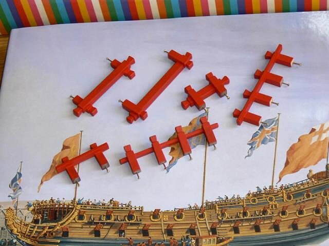
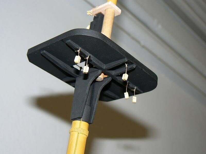
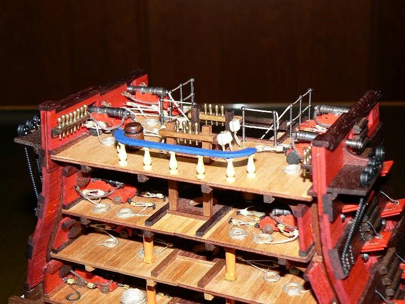
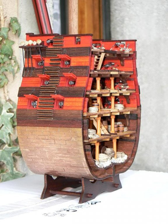
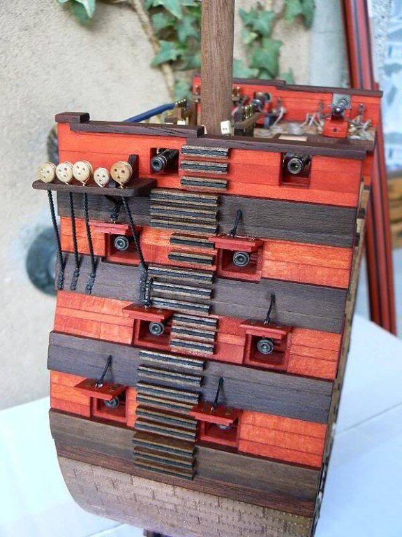
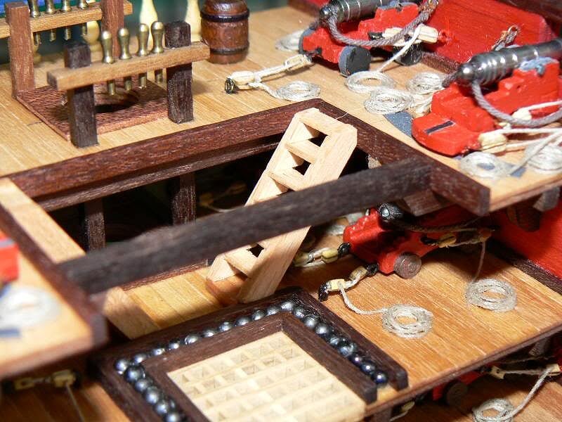
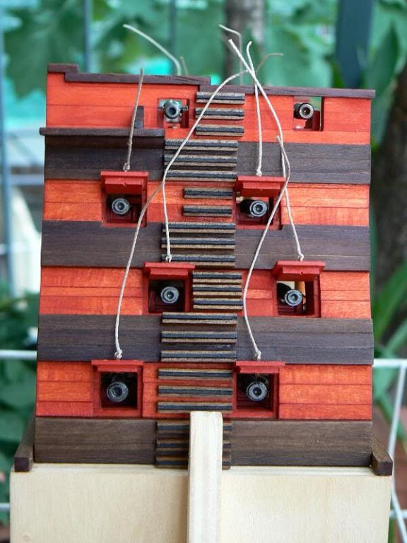
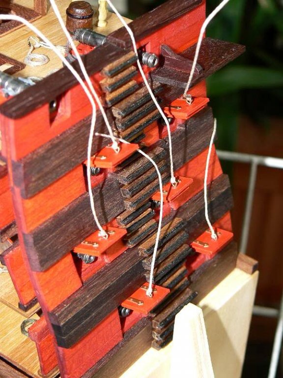
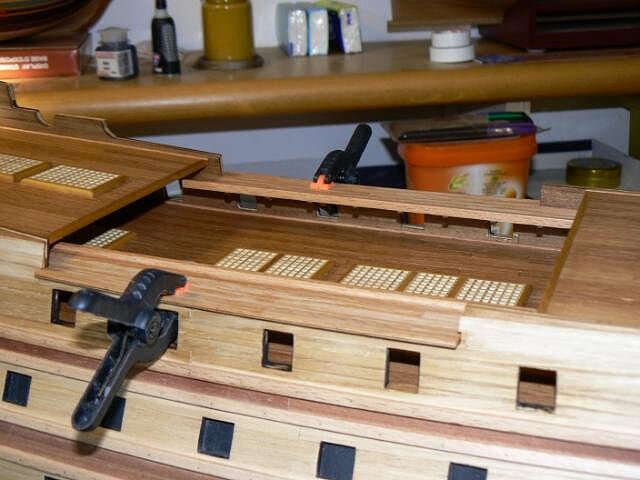
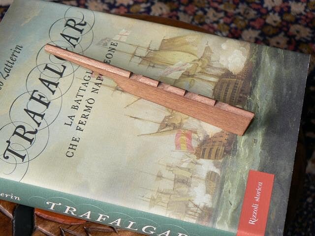
A quick update of the work done in these last days. First three images show the boats support structure, the pin-rails and the "pazienze" (I hope now that you can see them you can also name them corretly) after they are painted with red colour. They needed a total of three coats of paint to achieve a good result, So, just to paint then I took three days . .
01 P1080083.jpg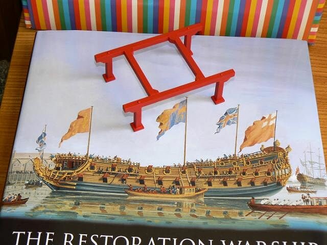
02 P1080080.jpg
03 P1080081.jpg
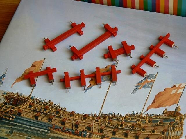
The pivots that come out from the bottom of these elements are the protruding part of brass nails fixed into the wood. They will be inserted in holes on the decks to increase the strength of the glue.
What do you think about the two decker shown on the cover of the book used as background ? It is a very interesting book about the plans, contruction and history of a 3rd rate vessel of 1678 named Lenox. It contains plans that would allow to build a 1:72 model . . The problem for me is that I have a lot of shipyards open and I cannot open another one !!
04 P1080082.jpg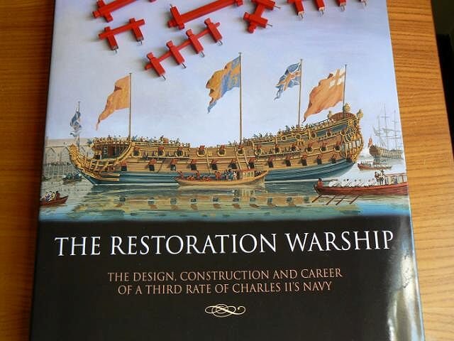
Kind regards, Jack.Aubrey -
July 16th, 2011
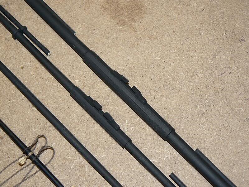
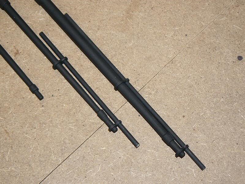
The next four images show the four yards of the main mast. They are still far to be finished . .
01 Cross%20Section%20Santisima%20Trinidad/P1070637.jpg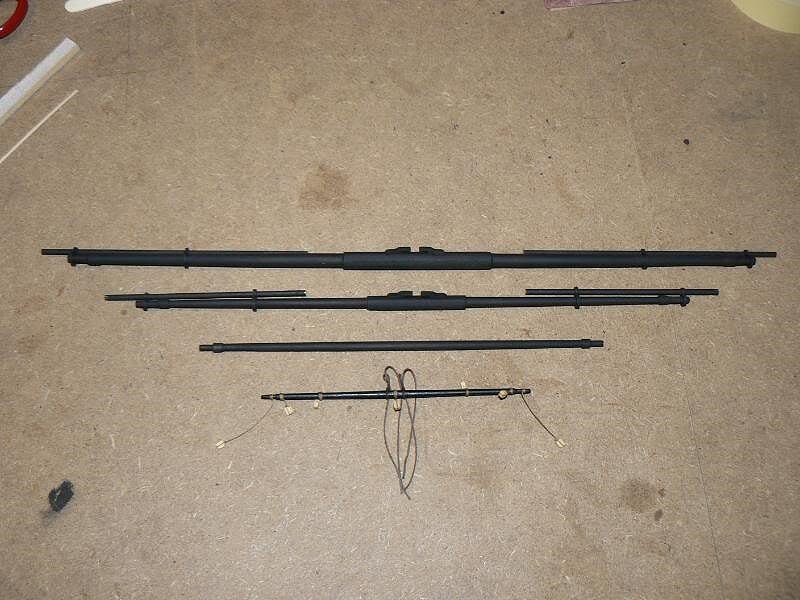
02 Cross%20Section%20Santisima%20Trinidad/P1070638.jpg
03 Cross%20Section%20Santisima%20Trinidad/P1070639.jpg
04 Cross%20Section%20Santisima%20Trinidad/P1070640.jpg
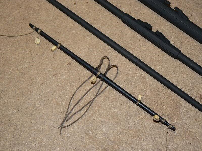
Now I'm preparing the last missing element of the mast, the topgallant mast. Then I will fix definitely all the elements together. That's all for now, cheers, Jack.Aubrey -
Tuesday March 6th 2012 . .
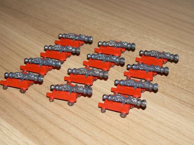
A preview of how the guns will appear on the trucks; the wheels are not yet painted.
01 P1080076.jpg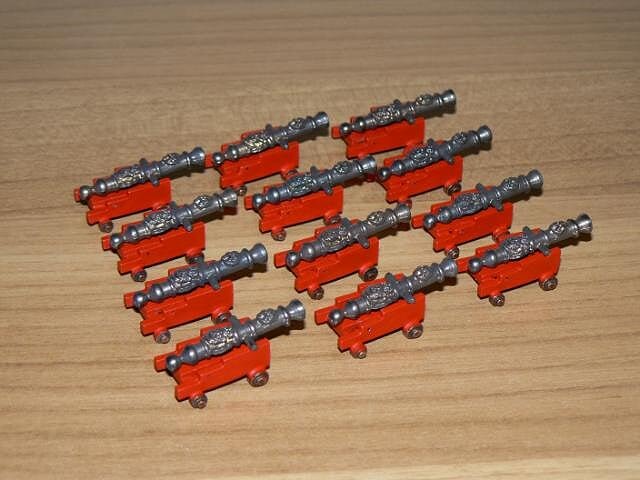
02 P1080077.jpg
-
Monday, March 5th, 2012 . .
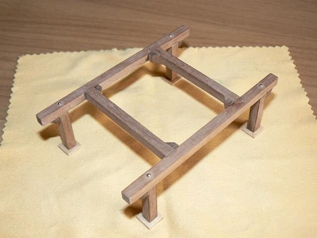
Today I built a "strange" structure (never seen on the naval achitecture books neither french nor english . . ) that has the role to support the ship boats. It will be located on the upper deck, just over the gratings of this deck. I had to built this element because, without positioning it over the deck, I can't identify the right place to install the ringbolts for some of the 12 guns. In fact this strucure interferes with them . .
Here below you can see the boats supporting structure: it is built with 5 x 5mm wood. Again my Proxxon table saw had a key role in cutting the single pieces, giving the warranty of perfect cuts at 90° that helps very much their assembly.
01 P1080067.jpg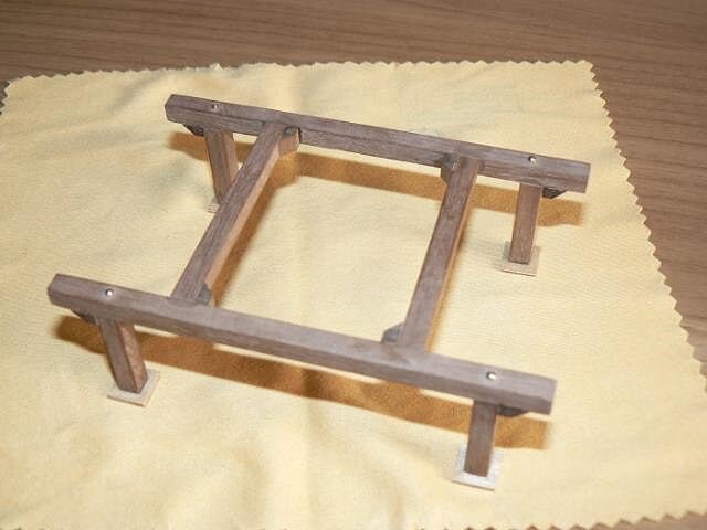
02 P1080068.jpg
Later I passed to the gun's trucks by painting them with red polyurethane enamel. I used a double adhesive tape to hold the trucks in order to paint them in a more comfortable way.
03 P1080070.jpg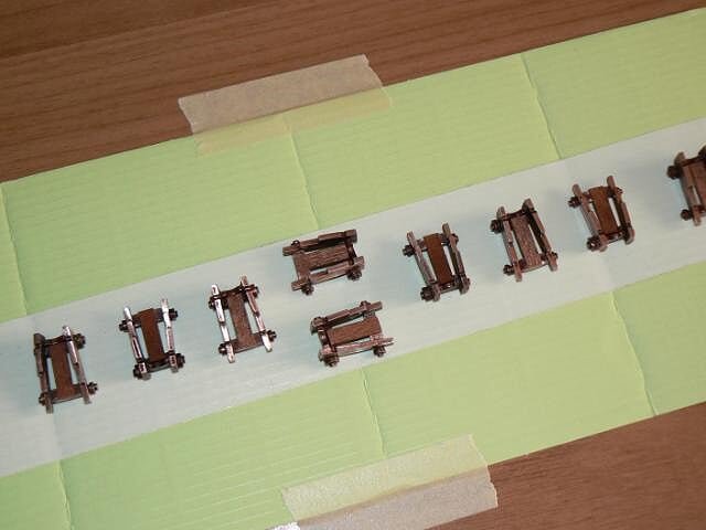
Here below the trucks after the first coat of paint. It is surely necessary a second coat, may be a third. I'm seriously considering the purchase of an air brush. I already have the air compressor. With an air brush these tasks will be surely faster. I will see on the market . .
04 P1080071.jpg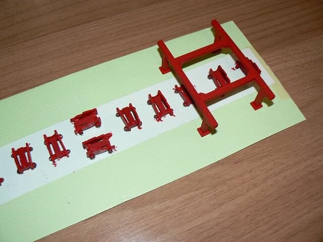
Kind regards, Jack.Aubrey. -
July 12th, 2011
I'm back from a very short holiday in Tuscany.
Here below I'm adding three images of other elements of the mast. In the first a detali of the lower mast. I decided to paint it with a pale yellow instead of leaving it in natural wood: in that period the masts usually were coloured in yellow and black. Yards were black.
01 Cross%20Section%20Santisima%20Trinidad/P1070635.jpg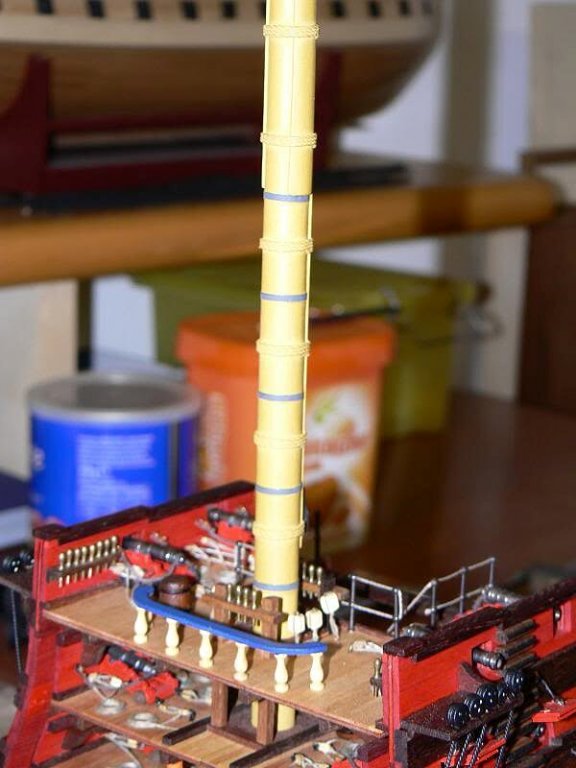
Here another image of the mast with other elements. They are here presented in place but not yet fixed. For the top mast I had to use another piece of wood because the one supplied by De Agostini was too much bent. On top there is the cross-tree. the topgallant mast is till missing.
02 Cross%20Section%20Santisima%20Trinidad/P1070641.jpg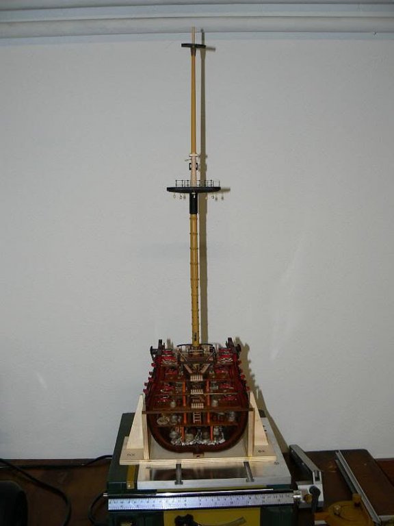
Here a detail of the cross-tree. It is a metal die cast piece and I have applied a coat of primer before the final paint same to the main top.
03 Cross%20Section%20Santisima%20Trinidad/P1070630.jpg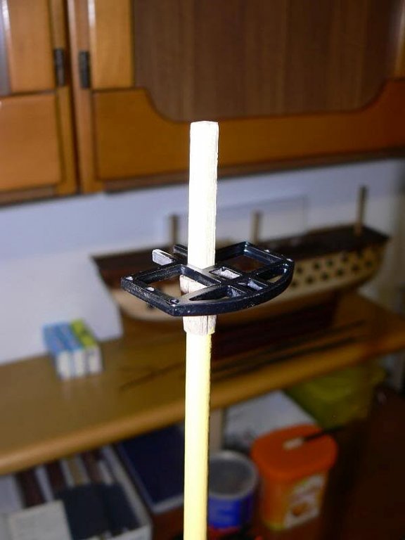
I have seen an image from another modeler that inspired me the kind of presentation for this model. Unfortunately I have lost the image and I can't show it. Having seen the features of this display case, I think that the basic idea to hang the whole (display case with the model inside) at a wall as a normal picture is very good.
See you next time, cheers, Jack.Aubrey. -
Monday July 4th, 2011 - Main Mast
It is nearly past a month from my last update and now I have something new to show. I had a lot of things to do not related to ship modeling and for this reason please don't expect too much . .
In summary, having finished all the activities planned for the hull, I started to prepare the single components of the main mast, four yards, lower mast, top mast, topgallant mast, main top, cross-tree and to assemply them.
My last experience of this kind belongs to more than 40 years ago, so I decided to follow without significant changes the instructions and expecially the plans supplied by De Agostini. But these sources are quite simplified: first all the rigging to and from the other masts is not present, and this has its own logic, but there is also a lot of masting and rigging details not reported on these plans.
To shape the yards and the masts I didn't use any power tool (i.e a lathe) but I made them using broken pieces of glass, sandpaper and sanding blocks: some fitness can be done also during shipmodeling !! Something was already shown some message ago.
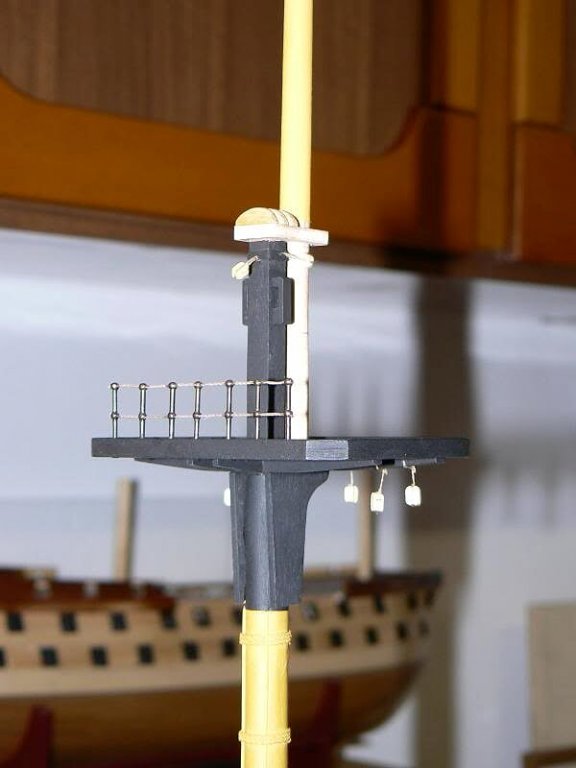
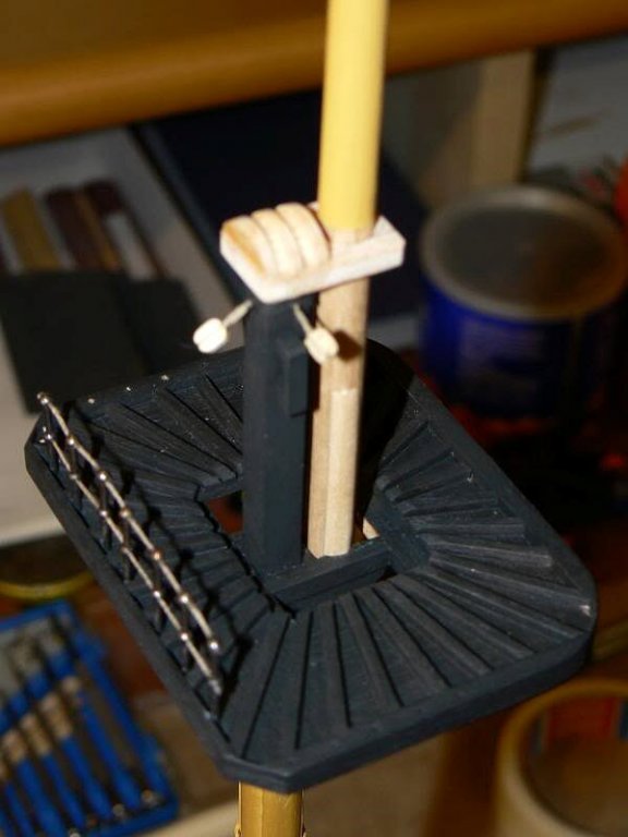
But the first important task was to build the main top. Here below it is possible to watch this elemnt from different perspectives. But I didn't use the supplied materials and I built it from scratch exactly as the top was built on the english vessels (I don't have documentation for spanish ships), even though a bit simplified. The black paint hides totally the big work done . . but for me it is imporant to know how it is built . .
Now the main top is fixed only to the lower mast, while the top mast and the cap are not yet mounted.
01 Cross%20Section%20Santisima%20Trinidad/P1070631.jpg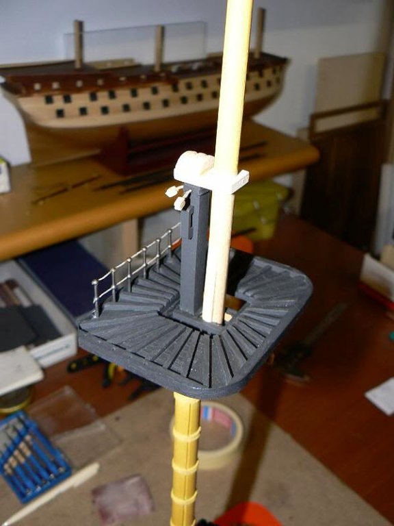
02 Cross%20Section%20Santisima%20Trinidad/P1070634.jpg
03 Cross%20Section%20Santisima%20Trinidad/P1070636.jpg
04 Cross%20Section%20Santisima%20Trinidad/P1070642.jpg
In a future message I will show better images of the lower mast and the top mast.
Cheers, Jack.Aubrey -
Sunday March 4th, 2012 . . "Pazienze" and "Cavigliere" (until I'll find the proper english term)
The building of the "pazienze" and the "cavigliere" raise another interesting matter. Infact, the vertical elements of these details, in this case a 5x5mm wood strip, must be "carved" to receive another 5x5 or 2x5 strip. The achievement of these notches is not difficult to do manually, it needs only some patience, but this time I wanted to find a different path to obtain the final result.
I'm slowly but relentlessy discovering new ways to use my Proxxon table saw and, for this task, I found another way to use it just to realise these notches.
The next image shows a trial made to achieve this result: I positioned the height of the saw in order to protrude only for few millemeters and, by passing the table above I made what you see in the image. Obviously I made several tests until I learnt totally the lesson, with some waste of wood.
01 P1080063.jpg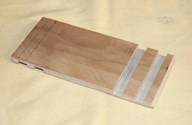
At this point of the test, I went forward to the next step: cutting the 5 x 5 square strip. But this is a normal use of the saw . .
02 P1080064.jpg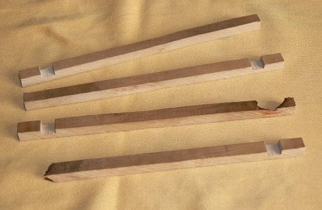
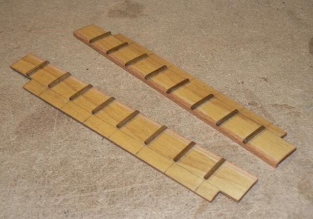
After these preliminary and successful tests I started to do the real work with the proper wood and the result can be seen in the next two images, the first with the wide notch for the "pazienze" and the second with the narrow one for the "cavigliere".
03 P1080065.jpg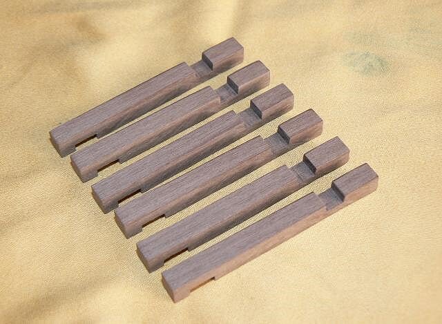
04 P1080066.jpg
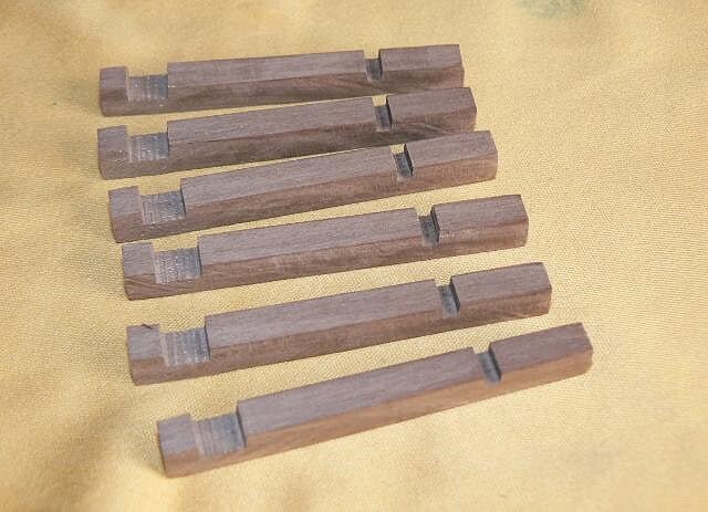
Obviously they are not finished at all, I have to carve the head in accordance with my last message and cut then to the right length.
But, again, I'm very satisfied because I made a new experience with the table saw . . experience to achieve step by step, error after error, until the final, successful way was found . . next time this experience will be ready for reuse in my mind.
At this point someone will probably asks by himself: and the guns ? They are still in the process but, having in mind the same experience with another model, I know it is a boring task and so I mix the work on them with other more interesting activities like the one described in this message.
See you next time, Jack.Aubrey -
Tuesday June 7th, 2011 - Last details on the hull
As I anticipated in my last message, yesterday I made the last additions to the hull:
- I completed the painting of the chain plates and the deadeyes
- I have mounted the handrails to the stepladders and also in another location I think these elements were probably in place, although the instructions did not mention them.
- last I built the last, bigger yard.
01 Cross%20Section%20Santisima%20Trinidad/P1070622.jpg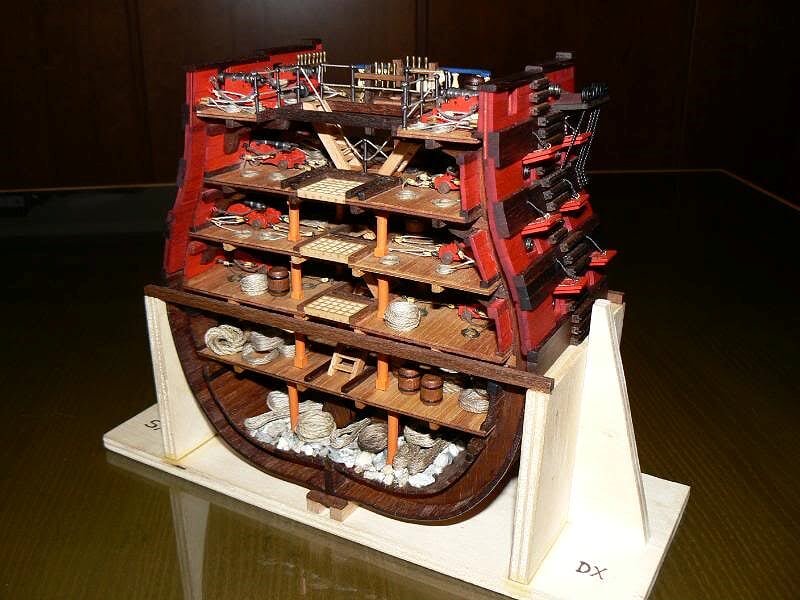
02 Cross%20Section%20Santisima%20Trinidad/P1070623.jpg
03 Cross%20Section%20Santisima%20Trinidad/P1070624.jpg
04 Cross%20Section%20Santisima%20Trinidad/P1070625.jpg
Now I'm concentrated on the masting; it is one of the last main tasks to achieve before completing the model. See you next time, Jack.Aubrey -
Sunday March 4th, 2012
After having built some pieces of the future ringbolts I found the power minidrill too fast and I preferred an alternative solution that can be managed in a more confortable way. I went back to my workshop and I found a manual drill I used when I didn't have the power tool. It was a lot of time I did not use it but it is very useful when you need to bore in area poorly accessible, given its limited size. The manual drill is shown here below
The process is the same than with the power tool, first of all you have to insert and fix inside the drill the to extremities of the wire.
01 P1080056.jpg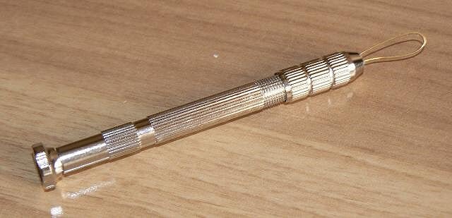
Once this task is done, a matter of few seconds, the ring is inserted around a pivot clamped in a vise. The pivot here shown is a drill bit of 1,5mm. Then you begin to twist the drill manually.
02 P1080057.jpg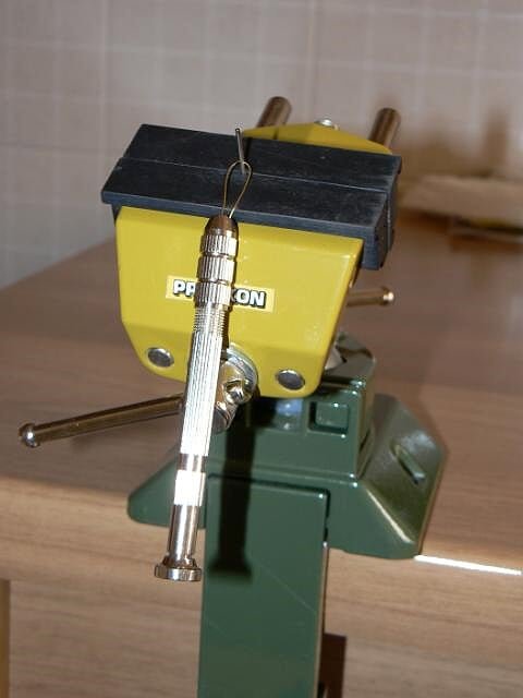
And here below you can see the result after the twisting. At this point I remove the piece and the process restarts from the beginning.
03 P1080058.jpg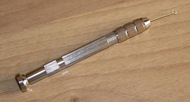
Today, in more/less 35 minutes, I made sixty of them.
After, I started to think how to build some elements of the superstructure of the decks. Some of these elements are what we call in italian language "cavigliere" (pin rails?) and "pazienze". I don't know the right english nautical terms, so I hope in some help from you to identify the proper terms. Anyway, in the future messages it will be possible to find these pieces completed. Here below I want to show two kinds of head finishing for these elements. The first image shows the classical solution, also proposed by the kit instructions . .
04 P1080061.jpg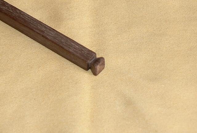
And here below an alternate solution to the classical scheme. The colour is not important because the final elements will be painted in red. The first solution needs more time and work than the second. I have to decide but I'm more interested in the first example.
05 P1080062.jpg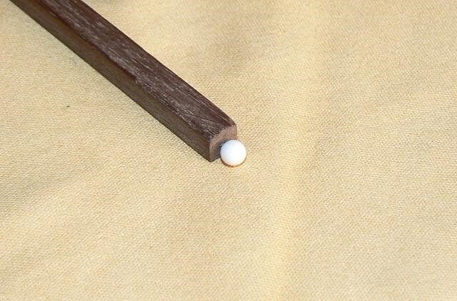
Cheers, Jack.Aubrey -
Sunday June 5th, 2011
Yesterday afternoon I have installed the handrails I anticipated in the previous message. They are 15mm. long and are quite plausible. I think it is necessary to keep in mind that on the real ship these details will be probably removed during the clearing activities before a gunfight. As soon as possible I will show the images of these details: I like them and I think to expand their usage to other areas.
Here below other images of the model as it was yesterday.
01 Cross%20Section%20Santisima%20Trinidad/P1070614.jpg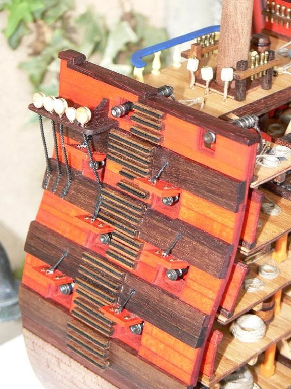
02 Cross%20Section%20Santisima%20Trinidad/P1070619.jpg
03 Cross%20Section%20Santisima%20Trinidad/P1070611.jpg
04 Cross%20Section%20Santisima%20Trinidad/P1070612.jpg
-
. . Continuation . . Friday March 2nd, 2012
As I wrote yesterday, having collected the materials needed by the next activities and having rationalised my mind, I started to work.
First of all the gun barrels: i mounted on my minidrill a wire brush and I cleaned all the barrels. This to remove any residual of filth from the object. The target was to make it ready to be immersed into the burnish solution. At the end of this task I immersed the barrels, all together, in the burnishing product and I left them there for about one hour. After this "bath", I washed the barrels under water to stop the process.
The result is visible here below. It is obvious I don't want to use any kind of paint but to leave the barrels as they appear in the image.
01 P1080050D.jpg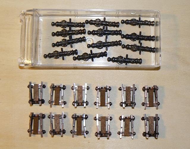
After I started working on the gun trucks. I bored each truck three times in the proper position to insert in the holes the ringbolts: two on the sides where there are the wheels and the last in the rear. I think it is difficult to see this holes, may be in the high resolution images.
Later I studied a solution that allows to fix the truck above the deck with a metal pivot. The objective is to fix better the trucks to the deck without having to rely only with the four bit of glue under the wheels. But this truck has no bottom useful to be bored to make the hole for the pivot. So I applied a small piece of hard wood 5x1mm fixed over the bottom. The solution is better understandable in the image. I'm sure it will work properly.
02 P1080050E.jpg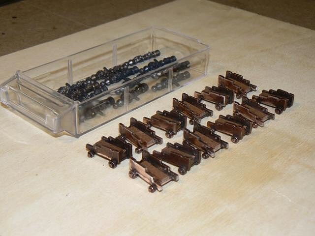
Then I started to build the ringbolts, or better one of the two pieces that make up a ringbolt. I used the brass wire shown in the previous message and I build them by using the minidrill . . to keep the ring diameter equal on all pieces I used a drill bit of 0,80mm diameter.
Here below some of these pieces are shown. They have now to be burnished.
03 P1080050F.jpg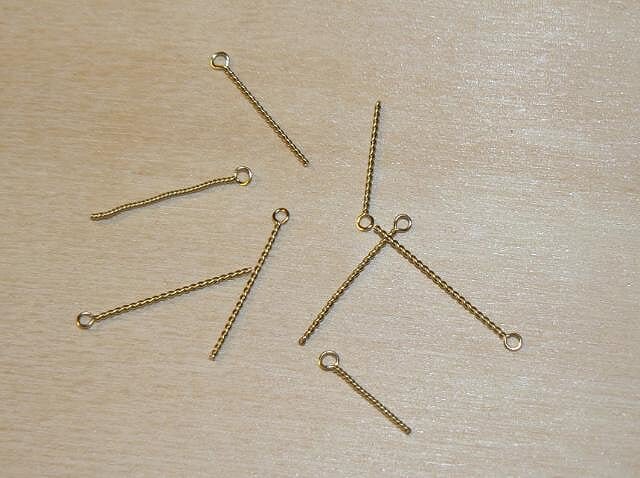
That's all for to day, see you next time, Jack.Aubrey -
Saturday June 4th, 2011
Having completed the hull with the installation of the gunport lids and later the chainplates, I started to prepare some components of the main mast. For this kind of activity I have to underline that my last, complete experience was made a lot of years ago, maybe 40/45 years ago when I was much younger.
To be well prepared to this new venture I spent some hours to study the masting & rigging plans supplied by De Agostini. These plans are the only real plans supplied by the kit manufacturer. Other plans (hull, decks, etc) are never supplied with this kind of collections and this fact is, for me, the main point of weakness of these products. The first impression is that these plans are quite simplified, if compared with some "holy" books describing masting and rigging, but you have to admit that a section has by definition an incomplete rigging . .
For this main reason and to avoid risks, I decided to follow the plans supplied, without changes or updates for new details.
First I started by building the yards, task that I considered free of risks to make errors. The yards are four in total of different diameter and length. The result, visible here below, was obtained without power tools: only files, sandpaper, sanding block, broken pieces of glass . .
Here below an image of the first three yards; the main yard is still missing and I will do it next . . in the meantime I will continue my studies of the rigging plan . .
01 Cross%20Section%20Santisima%20Trinidad/P1070621.jpg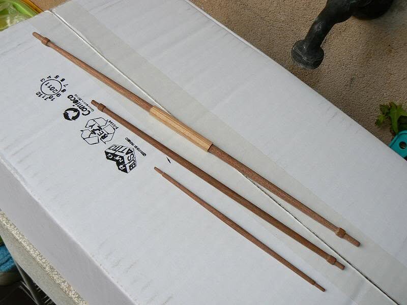
Here below other details of the hull. With the exclusion of the handrails for the stepladders, it can be considered 100% finished. The mast can be inserted in its final place without any kind of effort and . . miracle . . it is 100% vertical and straight, properties not always easy to find in a wood rod of 12mm diameter and with an overall length of +/- 50 cm.
02 Cross%20Section%20Santisima%20Trinidad/P1070617.jpg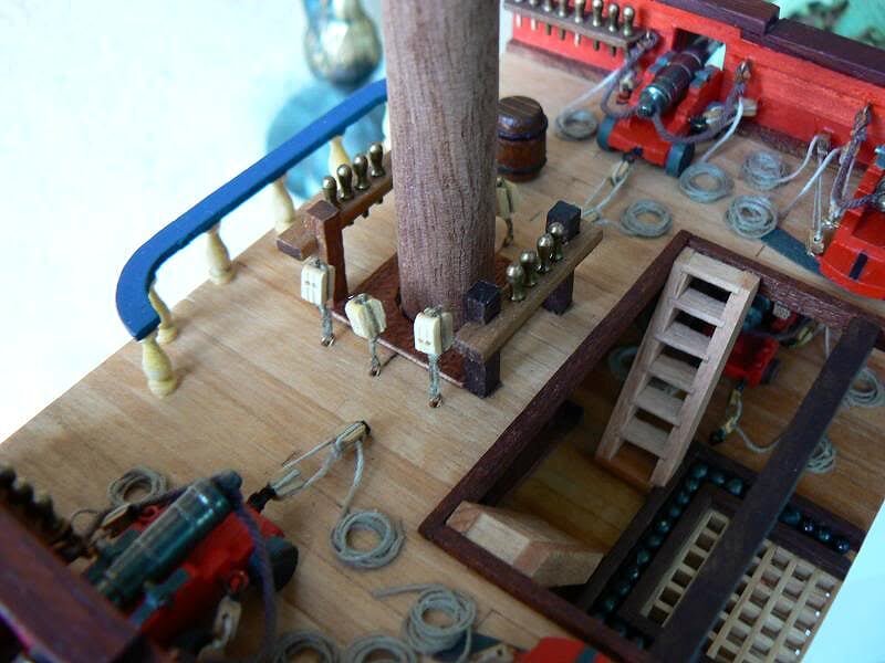
Here are finally visible the chainplates. I did not want to use the brass chains suggested in the instruction but I was not able to built then as they should be really done. This because my poor ability to weld. At the end I adopted the solution you can see here. Surely quite original . . but plausible ? I am not sure, I leave to you to judge . . surely very strong.
03 Cross%20Section%20Santisima%20Trinidad/P1070613.jpg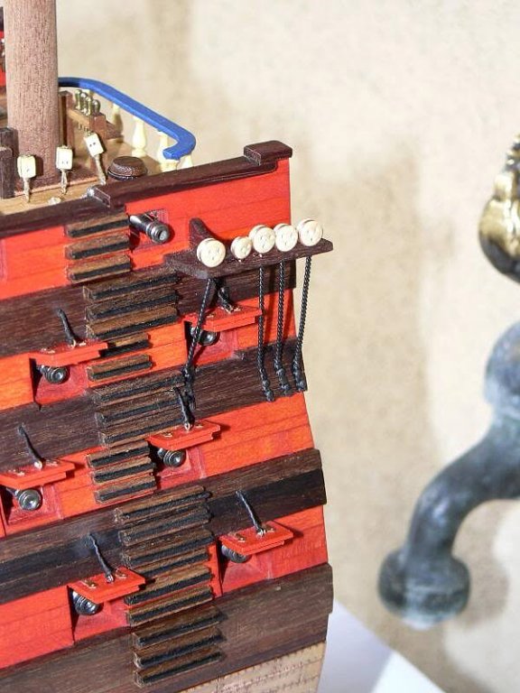
04 Cross%20Section%20Santisima%20Trinidad/P1070616.jpg
And finally I've found something that could be used to build the handrails. Again I found what I believe can be used in my "old pieces stock" and, if I well remember they should age +/- 40 years. As soon as possible I will install them and I will show to you.
See you next time, Jack.Aubrey. -
Thursday March 1st, 2012 - Guns
Today I spent some time to find the materials necessary for the installion of the 12 guns of the upper deck: gun barrels, trucks, ringbolts, blocks, rope, etc. These materials were shipped with sevaral issues of the magazine, so the search was not a matter of minutes but something more.
Having collected all the materials, I started the venture of installing these guns . . and honestly I think this job will take a certain amount of my time and efforts before writing the word "END".
In this first image you can see the main raw materials: 12 barrels and 12 trucks. Trucks are metal cast and I had to make some refinements with a set of small files and sandpaper to remove the many imperfections of the moulding. The image shows them already refined and you can also note that the metal used to cast them was in origin "aluminum" like and subsequently darkened outside.
01 P1080050A.jpg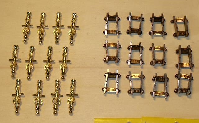
Image 02 shows the blocks that I was able to find in a model shop. Again I discarted the blocks supplied with the kit because they were too big for this scale. The new blocks are 3mm wide and what you can see in the left envelops are one-way blocks while the others on the right are two-ways blocks. Another important point is that these new blocks are not made from wood but from plactic. Each gun needs six blocks, three of the two-ways type and three of the one-way. In addition I show the strings that will be used for the tackles.
02 P1080050B.jpg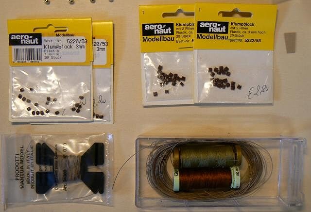
Image 03 shows the string to be used for the recoil ropes and a reel of brass wire that I will use to prepare the ringbolts. Each gun needs six ringbolts for the tackles and two for the recoil rope. I will scratch build them because, again, the ones supplied with the kit are, for me, out of scale. I have a personal method to prepare them that I will show soon.
03 P1080050C.jpg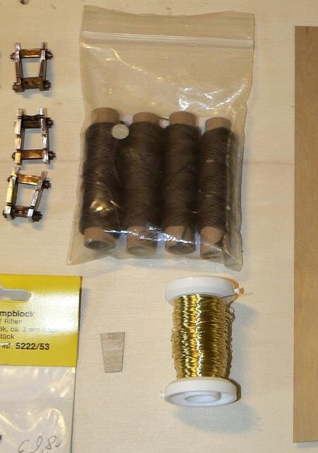
This is all what I need to start . . now I have to start . . see you next time, Jack. -
May 28th, 2011
Two images of a series of ten I shot recently. Here below in foreground are shown the two stepladders that make in communication the upper gun deck with the quarterdeck
I'd like to enrich these ladders with some additional details, such as handrails, details that 99% were in place on the real ship. I need to identify something useful for this feature.
01 Cross%20Section%20Santisima%20Trinidad/P1070596.jpg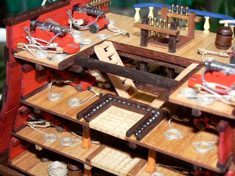
02 Cross%20Section%20Santisima%20Trinidad/P1070597.jpg
Yesterday afternoon I started to prepare the chain plates with their deadeyes. Again I didn't follow the instructions and instead of the brass chains supplied in the kit I used different materials. I will show more in the next messages.
Cheers. jack.Aubrey -
-
Other three images of the Soleil, same day . .
01 P1080040.jpg
02 P1080043.jpg
03 P1080039.jpg
-
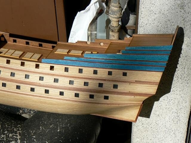
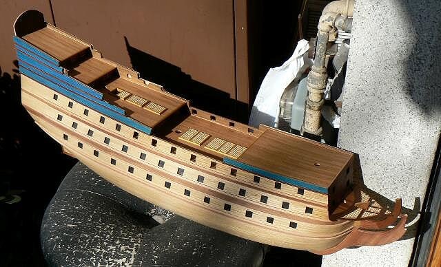
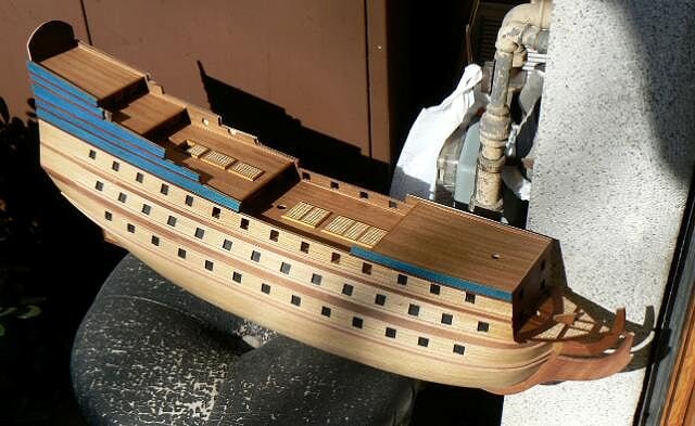
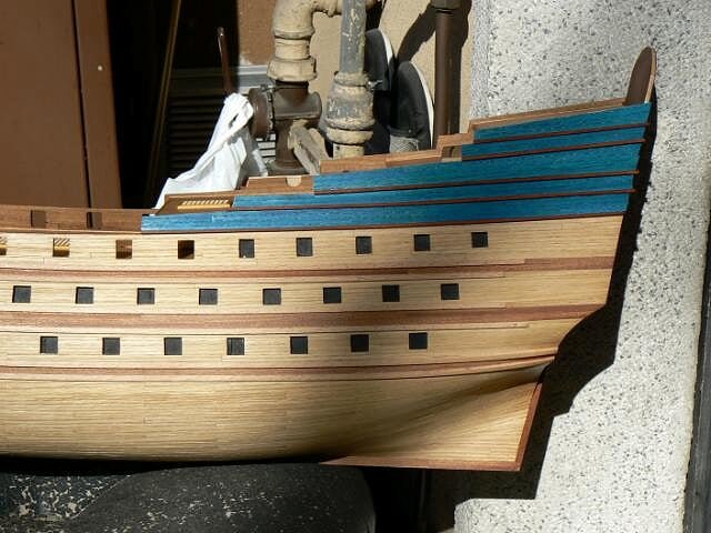
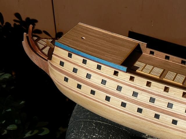
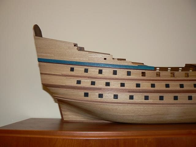
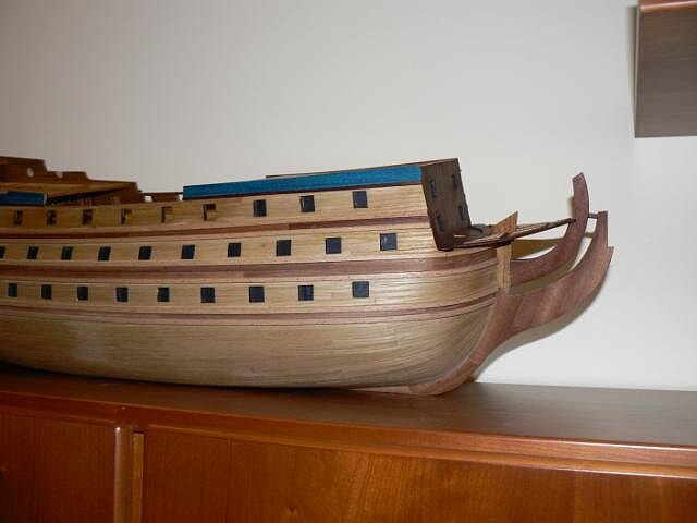
Monday February 27th, 2012 - Last wales and blue planks
During this week-end I have finished to install the "blue" planks and the last wales located from midship towards the poop. A relaxing task, without any kind of problems raised.
One interesting and amusing point was the preparation of the wales using the table saw . . every time I use it, I become more experienced and I learn something useful new.
Then I took the occasion of the nice weather to make photos outside. There are some tubes in the background that need some painting but the daylight helps very much to highlight the blue colour of the last work I made on this ship model.
And now I cannot delay an activity I don't love too much: install 12 guns on the upper gun deck before continuing with the installation of the waist above them. To install these guns I think to transfer the shipyard (or better only the materials I need) at home, in order to manage this boring work in several short session during the day without the need to leave my home.
See you soon, Jack.Aubrey
01 P1080037.jpg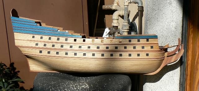
02 P1080038.jpg
03 P1080042.jpg
04 P1080044.jpg
-
May 26th, 2011 - Gun port lids
As I wrote yesterday, I built the gun port lids. I explained quite in detail the building process some messages ago. I had only to decide WHEN to apply them to the model and, obviously I had few arguments to think about to quickly decide to install them immediately !!
They are now definitely fixed in place and now there is only to insert the ropes into the holes bored in the hull and fix them with some glue to finish.
Here below some images of these details. First two are from the right side, the other from the left.
01 Cross%20Section%20Santisima%20Trinidad/P1070604.jpg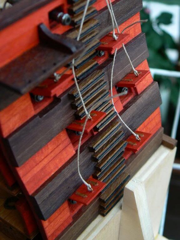
02 Cross%20Section%20Santisima%20Trinidad/P1070609.jpg
03 Cross%20Section%20Santisima%20Trinidad/P1070606.jpg
04 Cross%20Section%20Santisima%20Trinidad/P1070607.jpg
Its useless to write I'm very satisfied of this achievement, being it my first experience to build these elements. It will also be a very useful experience when I will resume another model, the San Juan Nepomuceno.
But they will not be only 12, they are 74 or more !
See you next time, Jack. -
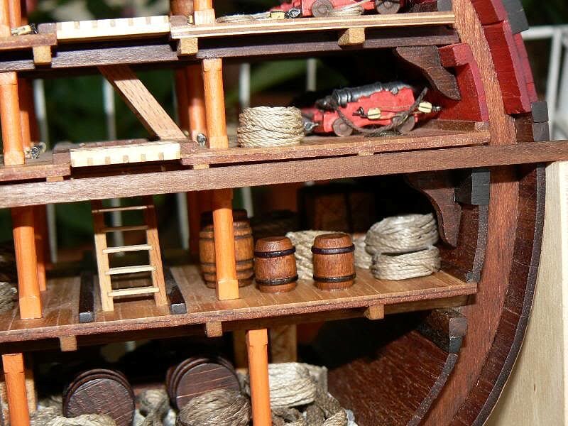
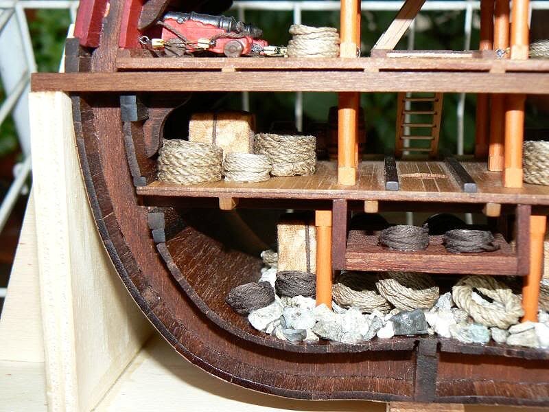
May 26th, 2012 - Ropes and reels
Here below four images showing the reels of hawser installed onto the lowest decks. First two images show the model as visible from the prow and the remaining from the poop . .
01 Cross%20Section%20Santisima%20Trinidad/P1070598.jpg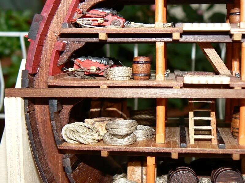
02 Cross%20Section%20Santisima%20Trinidad/P1070599.jpg
03 Cross%20Section%20Santisima%20Trinidad/P1070601.jpg
04 Cross%20Section%20Santisima%20Trinidad/P1070602.jpg
-
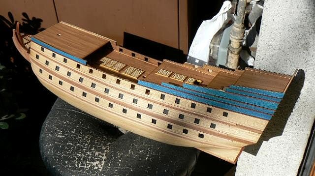
Thursday February 23rd, 2012 - Second thoughts about some planking . .
One of the future task to be undertaken on the hull sides above the upper gun deck is, in accordance with the kit manufacturer instructions, to paint this area with a light blue paint.
But I didn't like this approach. I like too much the colour and the grain of the wood to cover everything with paint . . and, after having spent weeks to achieve the result of carefully mixing different kinds of wood and taking also care to obtain a "perfect" work, I reached the same decision I took sometime ago to do not paint with dirty white the quickwork of the ship.
So I will not paint in light blue the upper sides of the ship.
In a store selling wood and related products I found a stain whose colour is blue, similar to the same, but red, I found for the Santìsima Trinidad Cross-Section. It is a powder to be diluted in normal water and its darkness/lightness is depending on the amount of water you use.
00 P1070807.jpg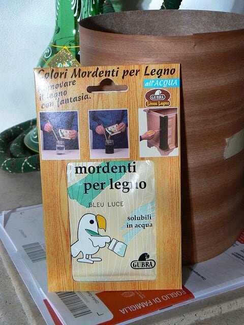
Sometime ago I made a test to apply this stain over the chestnut veneer and the result was very good regarding the colour but the problem was another: being this stain dilutable in water, there were big problems when installing the plank using the vinyl glue. The colour had the tendency to melt and dirty adjacent wood, and this was not a good thing.
I had to find a way to remove this unwanted effect.
I have then prepared some sheets of veneer with this stain and after I applied a light coat of wood filler above them. When the filler was dry I was able to discover that the colour was stable and did not expand or melt. This was the result I was looking for, so I decided to go further.
Then I started to re-plank the upper sides of the hull with this coloured veneer. But before starting with these new planks I had to install a wale above the gunports of the upper deck. This wale is 3 x 2mm ad was obtained by cutting in the right measure some strips of rosewood. Having mounted and glued this upper wale I installed some planks of the coloured veneer, eager to see the live result and to continue . . but the day was finishing so I shot some photoes that I immediately show you here below.
See you next time, Jack.
01 P1080034.jpg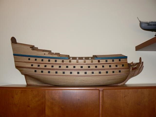
02 P1080035.jpg
03 P1080036.jpg
-
May 25th, 2011 - ropes and gunport lidsI finished to apply into the "belly" of the ship various reels of hawser. I made a relative positive experience with their preparation, with different sizes and shapes. I don't have images to show because I decided there is no need to bore you with similar, already published, photoes. But the realism, with these new components is becoming greater.The other work I undertook was the building of the gunport lids. I anticipated my decision to discard the metal frames supplied with the kit and to build them from scratch. And this is what I've done. Now they are ready to be installed in place, but I would like to spend some words to explain how I built them.The main elements used to build the lids are the following:
- square piece of plywood 13 x 13mm, 1mm thickness
- square piece of plywood 10 x 10mm, 1,5mm thickness; it is glued in the middle of the previous element
- two copper joints, arrow shaped, to fix on the external side of the lid.
- copper ringbolt, 0,75mm diameter for the gunport lid opening/closing
- a small piece of rope starting from the ringbolt and that will be inserted into a bore above the gunport, simulating the rope used to open and close the gunport.
Now I have to decide the proper moment to fix these lids to the hull . . the main concern is to identify the less risky moment to fix them.As soon as possible I will update this log. Cheers, Jack. - square piece of plywood 13 x 13mm, 1mm thickness
-
Thursday February 16th, 2012
Working around my Soleil Royal is still in progress . . yesterday I completed the two elements of the waist and I resumed the second planking to finally complete it. At this point of time I was able to finish only the right side and then I take a break . .
The image here below shows the finished side of the hull. Now there is to continue with the refinements of the circular gun ports, but they can wait . . may be tomorrow I will complete also the left side . .
01 P1080031R.jpg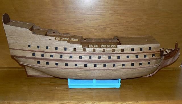
And now I will show the pieces for the waist. The first two images show these pieces above and below.
02 P1080029R.jpg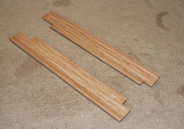
03 P1080030R.jpg
In the next two images I have positioned the waist on the hull, just to show how they will appear once installed in place. They are now larger that needed, but the proper adaptation to the hull can be done only during the real installation.
That's all for today, cheers, Jack.
04 P1080027.jpg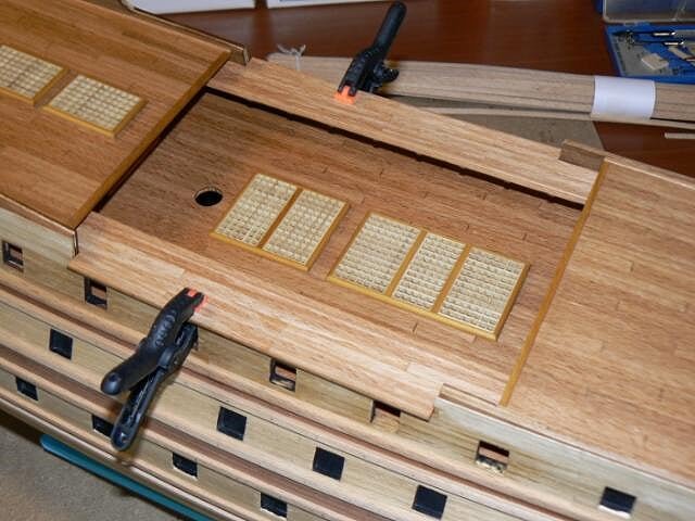
05 P1080028.jpg
-
February 15th, 2012
During these days I spent some time for planning the next macro activities, in the proper sequence. The planning can be summarized in the following list and sequence of actions:
- completion of the second planking in the upper side of the hull
- istall the gunwales and the remaining wales
- setup the elements of the waist
- install the visible guns of the upper gun deck, below what will become the waist
- install the waist
This is more or less the general plan for the next weeks. After, also if I don't know how much time I will need, I have to wait for new materials from De Agostini to continue . . and these shipments are a little late.
But let's come back to February 12th.
When I've simulated the positioning of the rudder with the "scratch built" pintles and gudgeons i discovered that the rudder I prepared was not good and was to be modified. The change was so conceived that I preferred to prepare another rudder, starting from a solid wood of mahogany. The problem arised was the difficulty to move the rudder with its current square shaped side adjacent to the stern.
Here below the image of the wrong shaped rudder to facilitate you in identifying the changes I made in the new one.
01 P1080011.jpg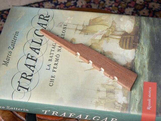
The new one also has a shape that is compliant with the rudders used at the times of Soleil Royal.
Here below a couple of images where you can see how the side associated with the stern is not square but arrow shaped. The fact I used solid wood has greatly speed up the time needed to build it and keeping the same visual effect.
02 P1080012.jpg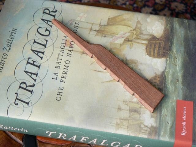
03 P1080014.jpg
Last, yesterday I began to prepare the pieces that will setup the waist. The pieces are made with birch plywood covered with beechwood planks. The overal thickness of this element is 2mm. The image here below shows the raw piece I prepared that will next be cut to form the two pieces required.
04 P1080023.jpg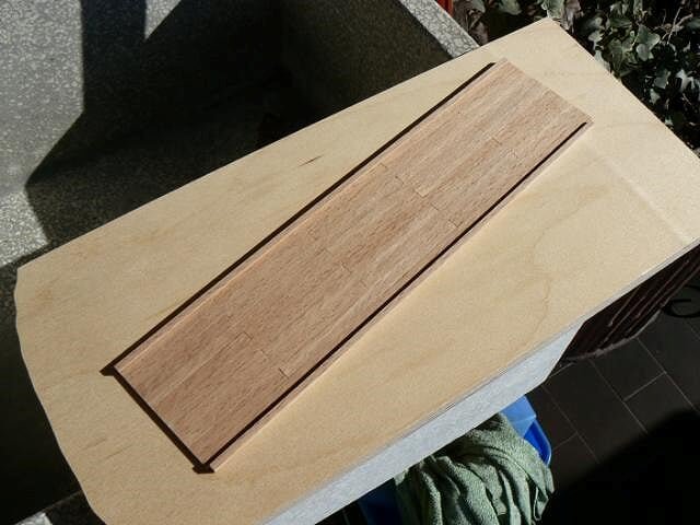
That's all for today, see you next time, Jack.Aubrey. -
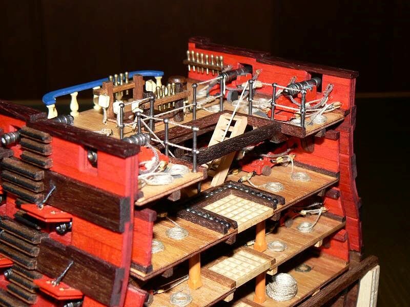
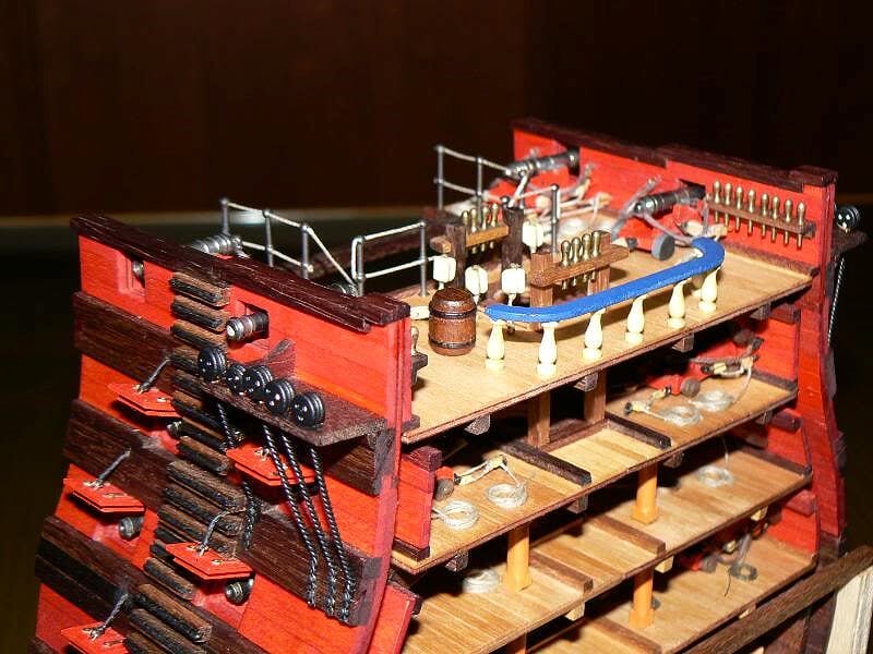
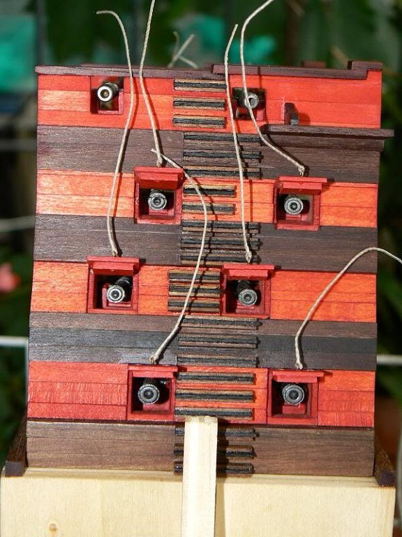
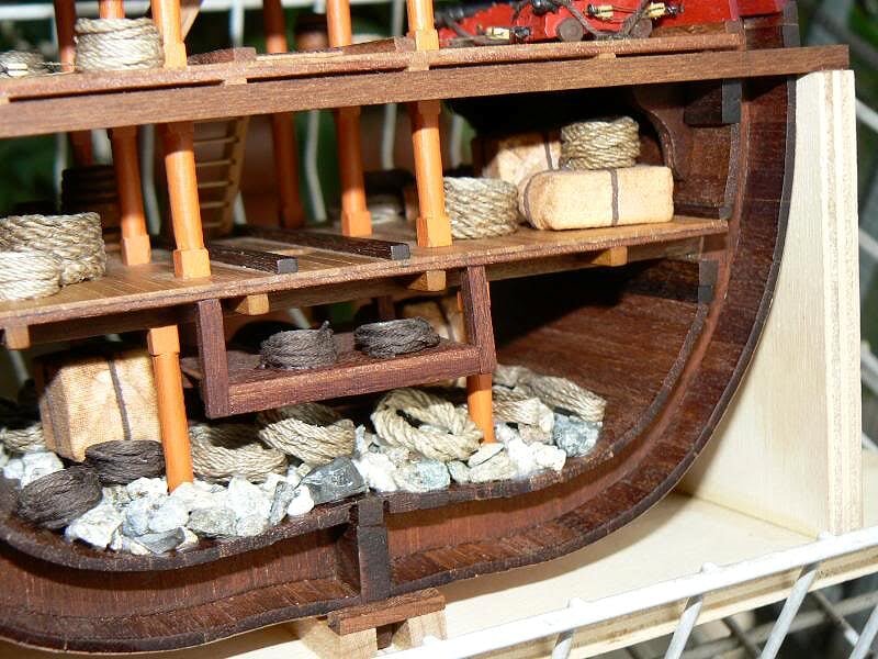
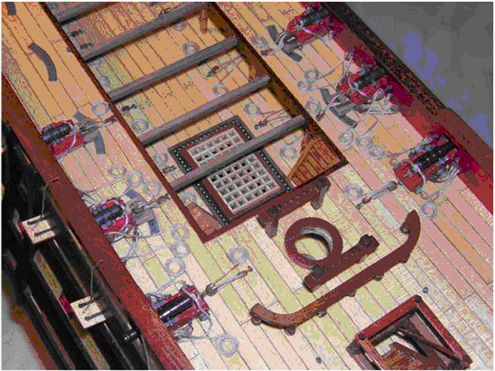
I had a question about the curved plates that are located under the Carronades (see picture above). Is that typical on ships to have this kind of plates as a reinforcement for the deck, I suppose?
In all the kits I have seen of American or British Brigs equipped with Carronades (example: Syren by Model Shipways), the carronades are directly installed on the wood of the deck, without any protection for their circular motion.
I'd like to know more about this feature if possible.
HI Yves, the curved plates located under the "obuseros" should work as a reinforcement of the deck against the movements and the usage of that guns. The same should be also the metal circle on the weels of the long guns, visible on the same image.
I discussed a lot with other modelers in a ship modeling association where I live and we came to the conclusion that may be a credible feature, although it is not documented in some books I have researched.
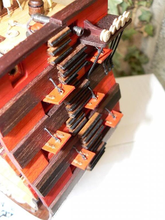
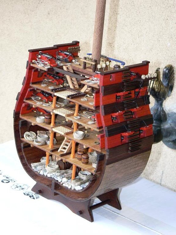
At the end I decided to do them after I viewed the image here below, representing the complete model of Santìsima Trinidad, the same model I presented some messages ago.
Anyway It is possible this kind of feature was never born, simply a source of discussion . . Regards, Jack.


Le Soleil Royal by jack.aubrey - FINISHED - De Agostini - Scale 1:70
in - Kit build logs for subjects built from 1501 - 1750
Posted · Edited by jack.aubrey
Thanks a lot Scott for you kind comment . . hope you will follow my work again. Jack.
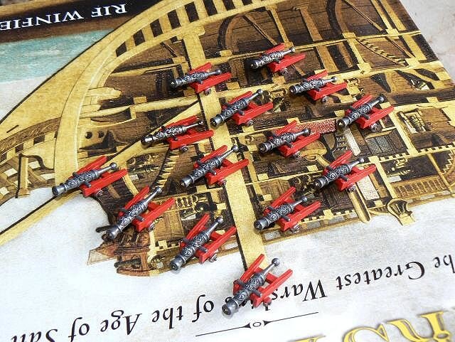
Last week I had too many things and they were not involving ship modeling, so the productivity was affected. Result: production below my usual average, average that is often lower than the rest of the world because of my slowness . .
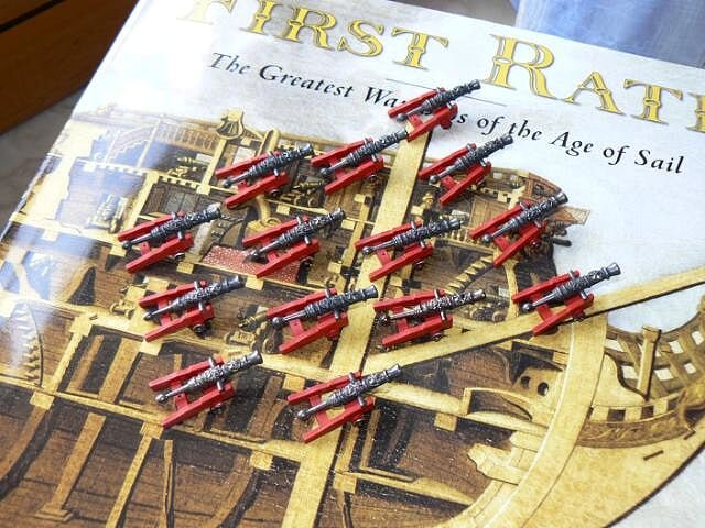
Here I post some images of the work done, just to show something, anyway uncomplete. In the first two images the guns for the forecastle and the quarterdeck, different from the guns of the upper deck, with their red painted trucks. Again the wheel are not painted.
01 P1080084.jpg
02 P1080085.jpg
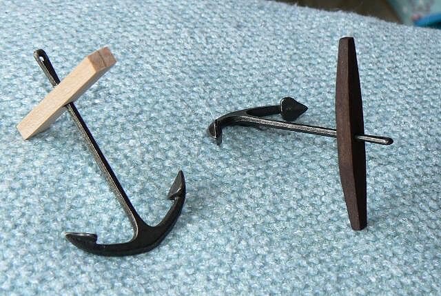
Then I started to build the four anchors. I'm still far from the end and here I show one anchor with the raw wooden stock and the other with the same element shaped and stained. Today I made all of them, including the iron hoops. For these last details I used a personal method instead of the one suggested by the instructions. I will explain better in the next message which will include finished anchors images.
03 P1080086.jpg
04 P1080087.jpg

Kind regards, Jack.Aubrey.