


jack.aubrey
-
Posts
1,268 -
Joined
-
Last visited
Content Type
Profiles
Forums
Gallery
Events
Posts posted by jack.aubrey
-
-
-
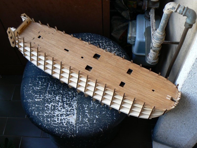
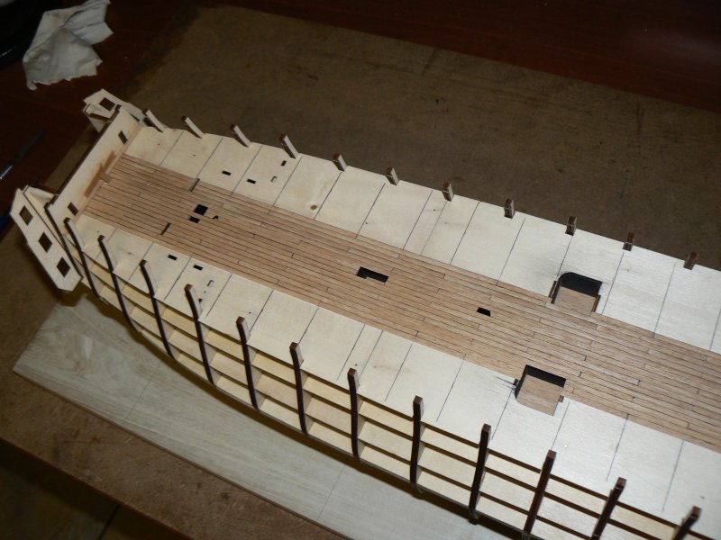
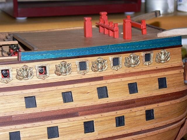
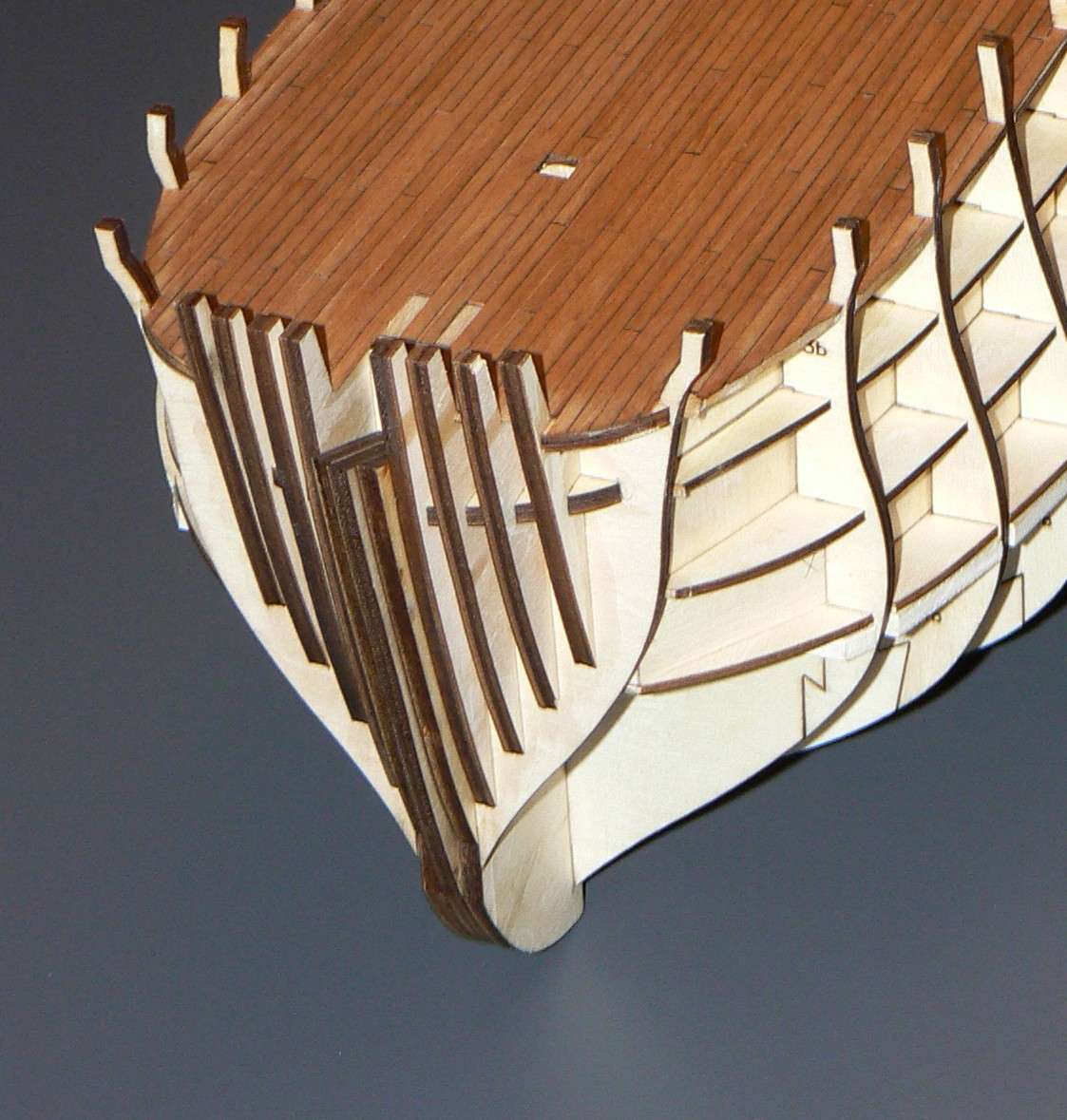
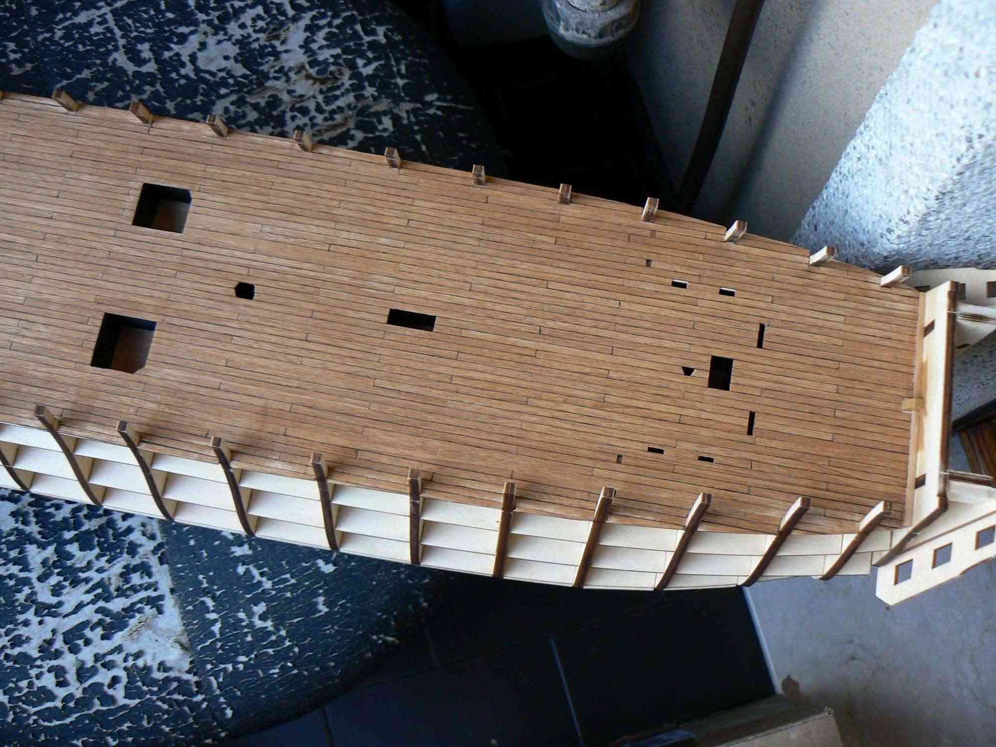
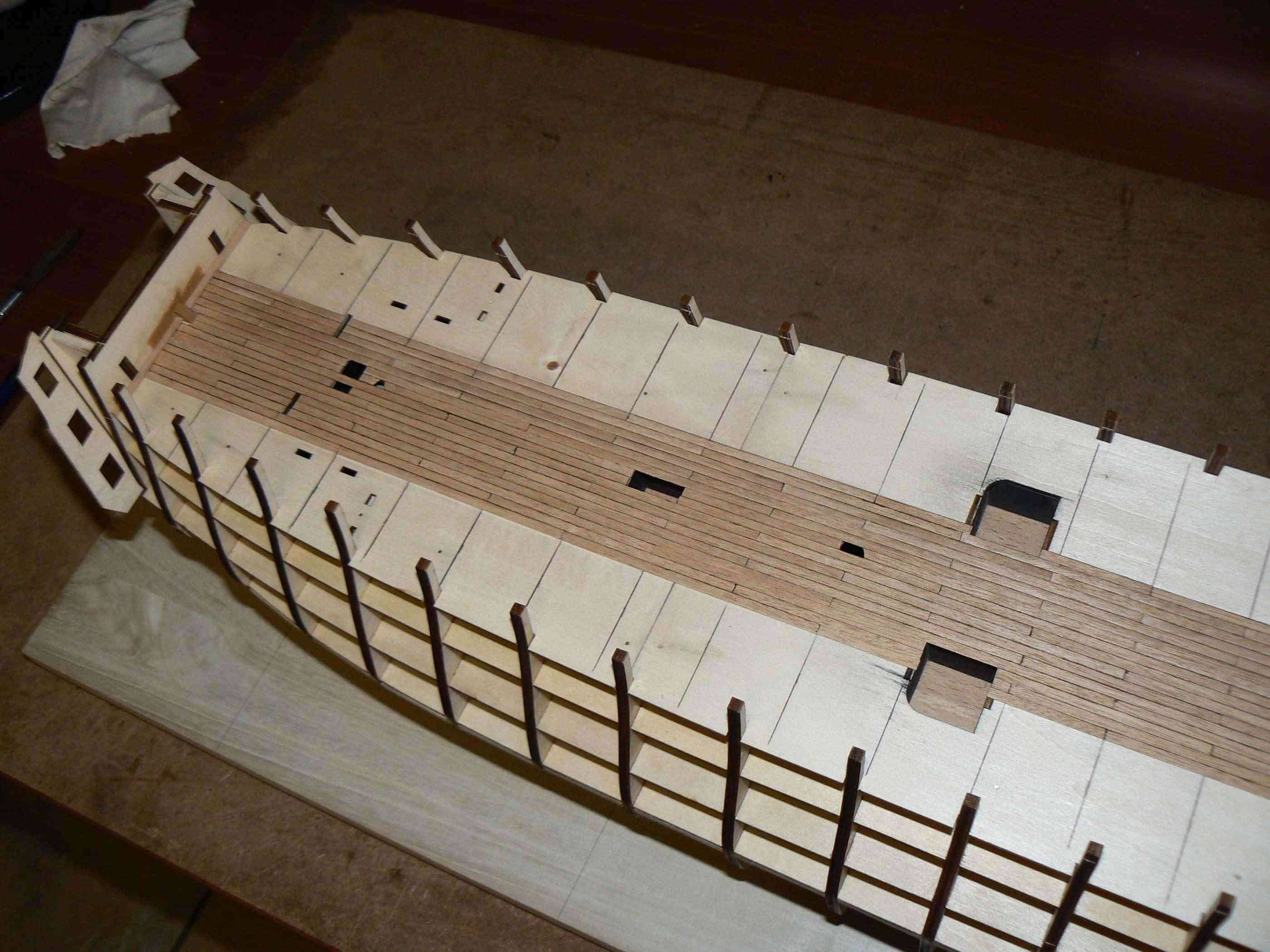
August 9th, 2013I'm studying the bow with in mind the beveling of this area: the instructions are clear but there is something that does not convince me completely. . I have to meditate on it.In order to provide an explanation I help myself with the images that show in detail the bow area, which as you can see is still untouched. Photo 01 and photo 02 are the same, except that on the 02 I pulled a few lines and letters for reference.If we read the text and look at the pictures of the mounting instructions ranging from issue 24 to issue 30. They are pretty clear in their entirety. Above all it is clearly seen that the planks applied on the right side and left side are glued in close contact between them over the thickness of the keel, that is the element marked by the letter "A" in picture 02.This makes me thinking that the element "A" must be sanded to obtain a shape similar to a very enlarged 'V', well centered on the centre line of the keel. Finally I would like to point out that since this element is 4mm thick. we dedicate 2mm. for the planks of the right side and 2mm. for those on the left. . it seems a little bit as a base for an effective bonding.01
 This leaves me really doubtful but let's continue . .Let's now look at the two items marked with the letter "B". They are glued on the sides of element "A", then they strengthen it. But do not come to the same level with "A", as the reinforcement elements at the lower of the stem. They stop first at about 2-3mm . This does not make sense . . unless the element "A" should remain as it is and planks should rest just above the two "B", of course beveled with the right angle!If so, the planks should lay on the elements "B" and "D". Also the element "D" will obviously have to be smoothed with the right bevel.But rather than clarify my doubts, they are further complicated. .02
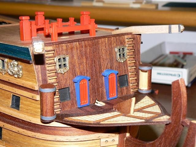
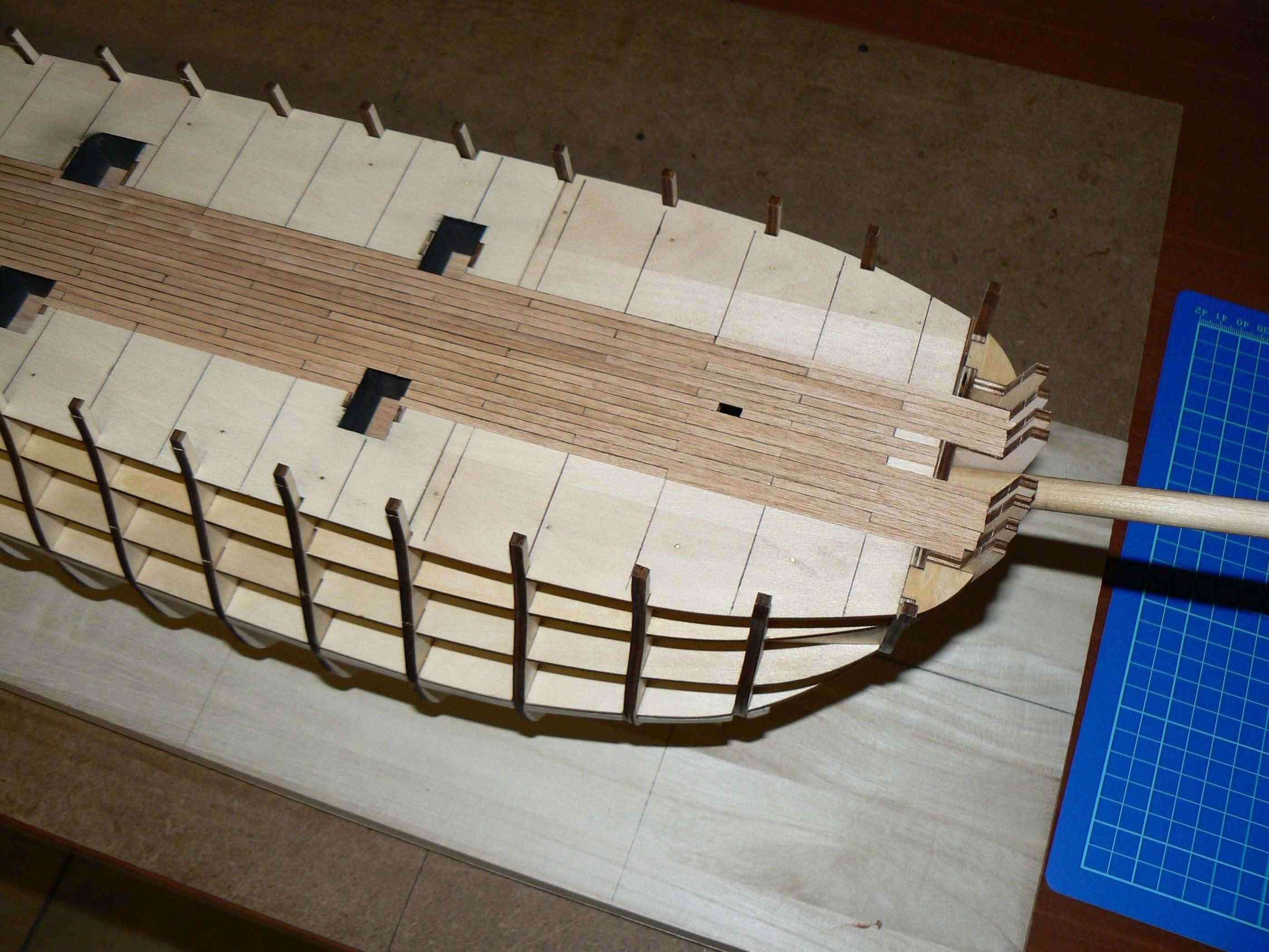
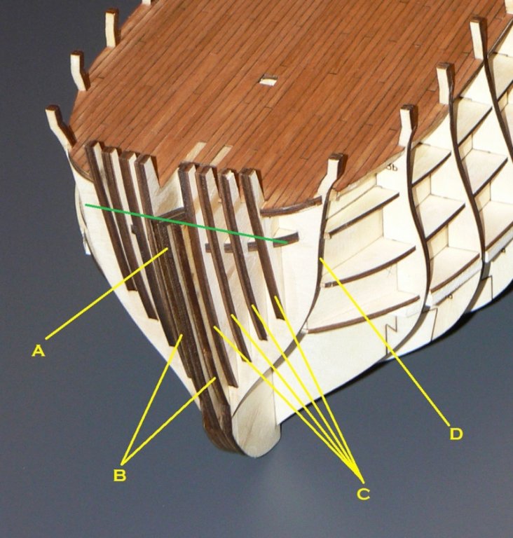 At this point, what is the objective of the pieces marked with the letter "C" ? It it unlikely that the planks should lay on these items . . they are too small with respect to the curve that the planks must necessarily assume in this area.For me, the function of the elements "C" comes into play only when you reach, with the planks, the line that I drew in green, where the hull has to bend further to rest on the eight "scalmotti", left and right, which protrude from the bridge.Now don't ask me what is right, I do not know, I just limited to explain my concerns and I find now that I'm writing that in another forum a user showed that the DVD, attached to issue #1, provides a different approach from the instructions . . . and this a little bit confirms my thought.One last thing: in next issues we will be provided with pre-cut elements for the keel and the bow; were will lay these pieces on the bow? On planks above the element "A" ? Unlikely, most likely on the element "A", by removing part of them to obtain a gap to insert these new pieces. A nice dilemma. .And finally, I have not even approached the stern!!High Resolution Images:
-
Saturday, October 13, 2012 - Gun port lids
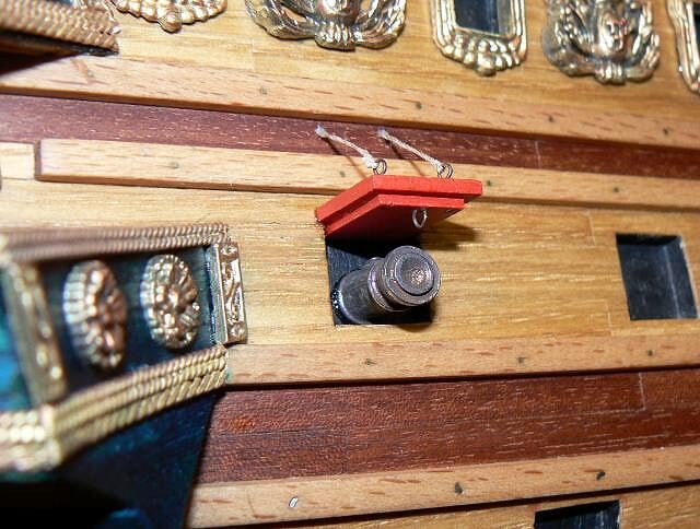
As I have previously written, I changed all the necessary material for the gun-port lids because I wanted to implement a method of securing themselves to the hull that was very strong. In fact the pieces proposed in the kit, although correct from a formal point of view, do not provide any appropriate method to fix them on the hull.
So, as I wrote, I re-did from scratch everything. For the larger square, originally plywood with 2mm thickness, I did it again using plywood (1.5 mm) on which I glued strips of chestnut veneer (0.5 mm), the same wood used for the second planking of the hull. I have prepared in this way bars of 15 x 10 cm and then I cut with the table saw piece to piece.
Regarding the second piece, the smaller square, I re-did it in a different form: instead of square I made it rectangular, so that it protrudes from a side of about 3mm from the larger square element. If you look at the picture below you will easily understand what it came out.
Then glueing the two pieces together using a template to ensure all result the same and, finally red acrylic paint of the inside.
01 P1080403.jpg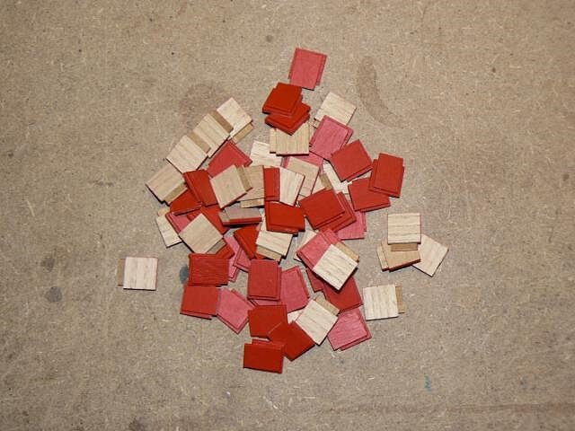
Then it was the turn of the eyebolts. Those proposed by the kit are out of scale for me.
I opted for building from brass wire/thread. The ring has an inner diameter of 0.75 mm. Must be burnished prior to assembly.
02 P1080409.jpg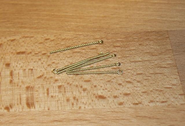
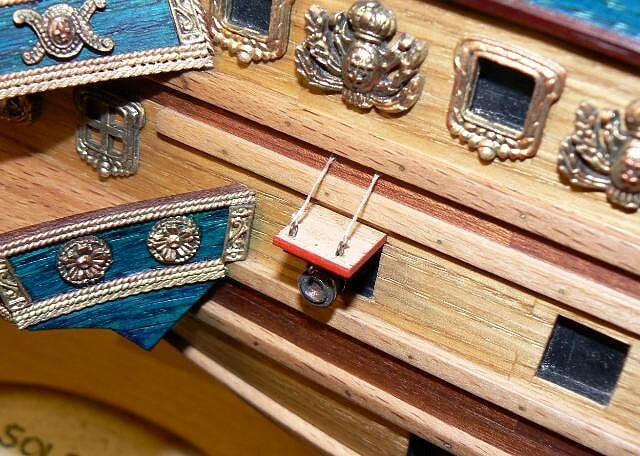
I developed a prototype that I brought up to the final assembly stage, to see if it satisfied me. It is visible in the three images that follow. The eyebolts used have an internal diameter of 1.5 mm as I have used material already available to accelerate the process. The final version will use the smaller ones. I also have in mind further improvements.
For gluing the lid to the hull, as well as the half-barrel, I used two-components epoxy glue. I've seen that this glue provides a very strong bonding. For the lid would be enough the vinyl glue, but since I had already prepared the epoxy I used the latter. But I think the epoxy is much more tenacious, then I'll probably use this one for the future.
03 P1080410.jpg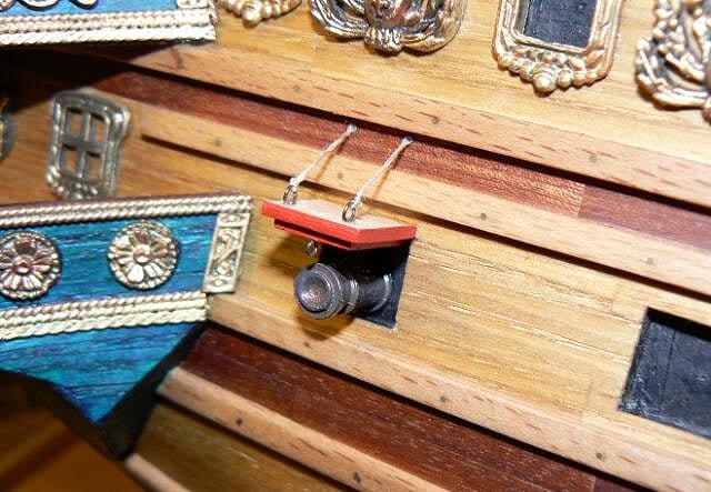
04 P1080411.jpg
05 P1080413.jpg
Once finished the prototype now I have to move to mass production for all the rest. The work to be done is a lot: about 200 eyebolts, three holes for door, assembly, ropes, etc.. For the moment, what I wanted was the prototype while for the rest there is time, since before there are more important things to do.
See you next time, Jack.Aubrey. -
Wednesday, October 11, 2012 - Third ship boat
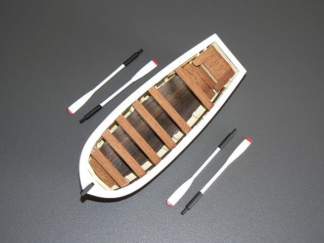
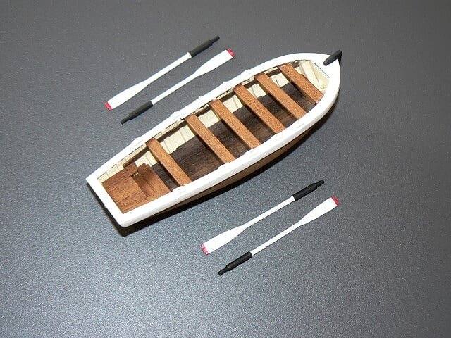
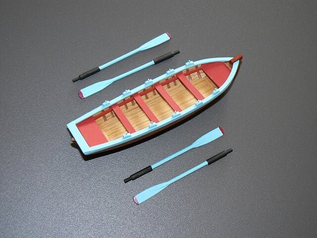
As I wrote a few messages ago, I decided to build a third boat for my Soleil Royal. This boat that will be exposed on the basement of the case, as I decided for the larger of the two I built before, whose material was included in the kit.
I used a project already in my hands for some time and some work done in the past.
Here below some pictures of the longboat under construction and still unfinished.
01 disappeared thanks to DeAgostiniPassion.it
02
 disappeared thanks to DeAgostiniPassion.it
03
 disappeared thanks to DeAgostiniPassion.it
04
 disappeared thanks to DeAgostiniPassion.it
Yesterday afternoon and Monday I prepared the gun port lids that will be installed of the lower and intermediate decks. For the solution that I had in mind the pre-cut material supplied by DeAgostini was not suitable, not so much for the pieces themselves as the lack of an adequate system of fixing to the hull. So I've built the lids from scratch using other material. For the moment I am still in the process, even though I already painted the inside in red. In the coming days I could show you how I imagine the necessary finishes that I have in mind: hinges, rings and ropes for their opening and closing . .
Sincerely, Jack. -
Below a possible idea of how to position and present the ship boats, externally to the model, on the display case basement. If we exclude the black base which of course is not needed, this presentation system would have two advantages: allow to display the boat with more viewpoints visible and the possibility of fixing the boat base to the basement with a simple double-sided tape. .
01 pinfin4_863.jpg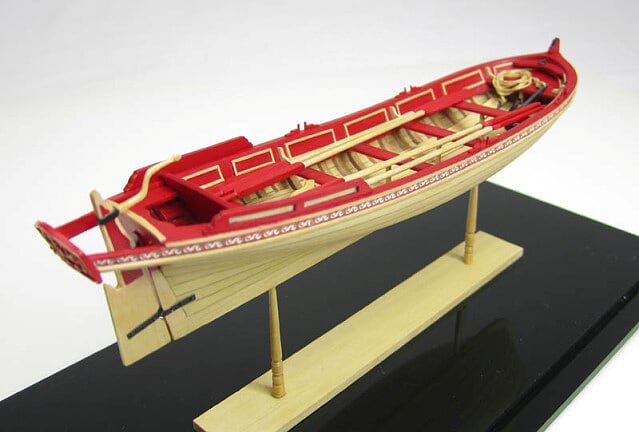
Cheers, Jack.Aubrey. -
Monday October 8, 2012
I've almost finished the building of the display case: now the only part missing is the plexiglass cover, but this can wait sometime. I have started and finished a couple of tasks that I left behind, such as the browning of all decorative elements.
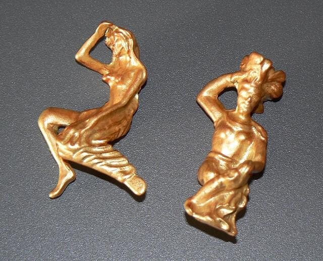
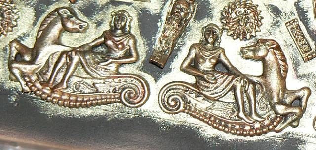
In particular, I have devoted great attention to the figurehead and a couple of human figures that will be placed at the stern. In the photographs they seem worst as they appear in real life, but I'm not happy with the result: they seem to me a little vanishing, as if there were no reliefs enhancing the depth effect. Before installing them I'll wait to find some ideas to increase their realism.
01 P1080397.jpg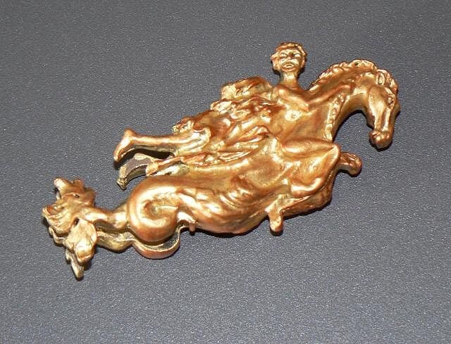
02 P1080398.jpg
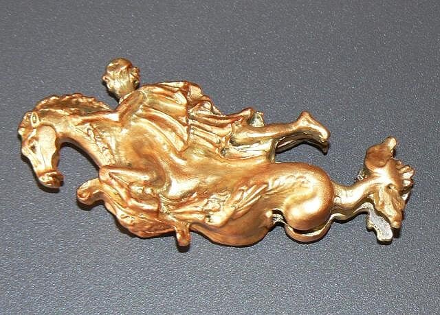
03 P1080400.jpg
Then I started the preliminaries for a new task: the installation of metal small columns that will be the basis of the gunwales all around the decks. As a logical consequence of having all the metal decorations properly gilded I can't leave the columns as they were originally delivered. . there would be an inconsistency so I took the decision to treat them too, although this would force me to spend much more time than usual.
I guess now you all understand why the model progresses so slowly. . and the remarkable qualities of patience I developed in this adventure, qualities that I didn't absolutely have before . .
After the application of two coats of primer I had two options: gold paint or another color. At the end, I opted to color them in red (but after having also evaluated the blue color). Maybe this choice will appear a little crazy to most of you but I think there's already enough gold on this model . .
04 P1080402.jpg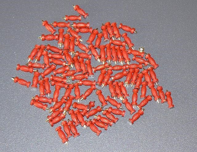
Cheers, Jack.Aubrey. -
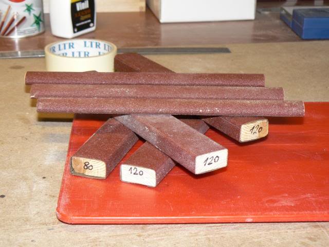
Yesterday I started to prepare sanding blocks with new sandpaper sheets. The ones I have used so far were built several months ago and now they no longer have the original abrasive power . . hence the decision to redo them. What I call "sandpaper" is not the simple paper that is available commercially at a cheap price but a more sophisticated product that has a much greater duration so it can be used without problems for a long time. Of course initially these blocks will be used to bevel the bulkheads.Below I show my inventory of these blocks, before changing the sandpaper.01
 02
02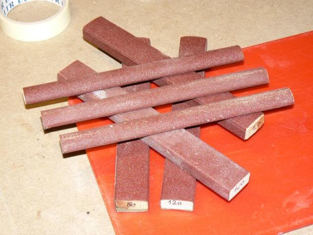 03
03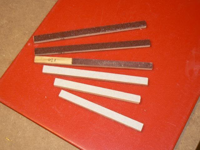 Cheers, Jack.Aubrey.
-
Thursday, October 4, 2012
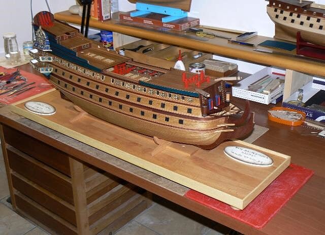
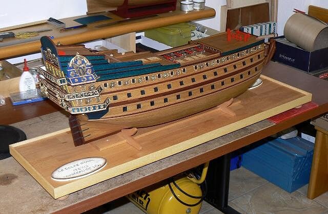
To complete the images of the above messages, here is the display case base with the model in place . .
Regarding possible display variants I decided to build a third boat, in place of the two proposed by the kit manufacturer, more precisely, I would like to build a longboat.
Then I decided to put only one of these three boats, perhaps the smallest, over the structure (this structure is a bit strange indeed, I've never seen a similar one on other models) that should host it amidships.
I'm going to show the other two boats not aboard but on the base of the case in a suitable position. This would allow a better overview of the details in place in the central area of the deck, certainly less crowded and to increase the visibility of these boats, presented separately. I spent a lot of time to build these boats and I would like to better appreciate them.
I did some simulations and the idea likes me very much . .
01 P1080394.jpg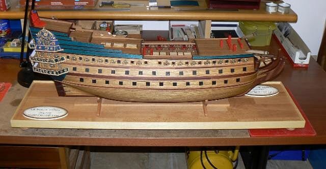
02 P1080395.jpg
03 P1080396.jpg
Greetings, Jack. -
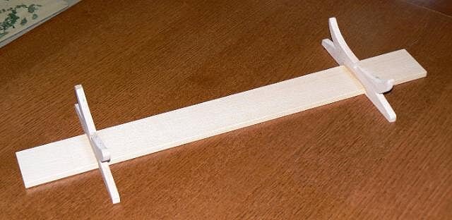
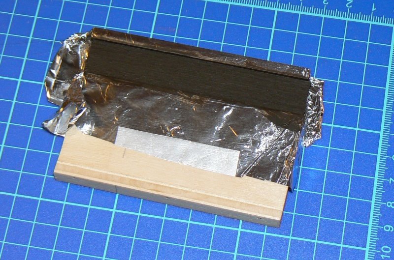
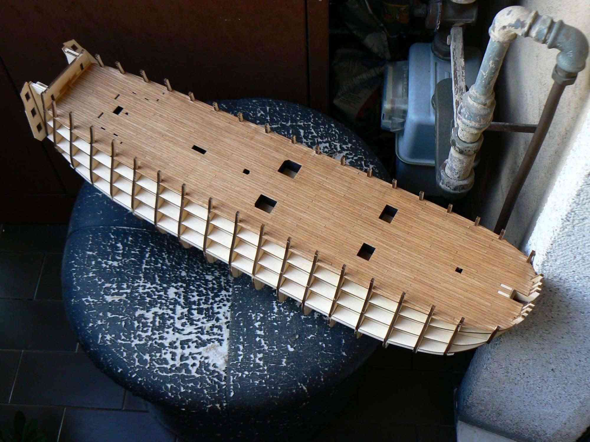
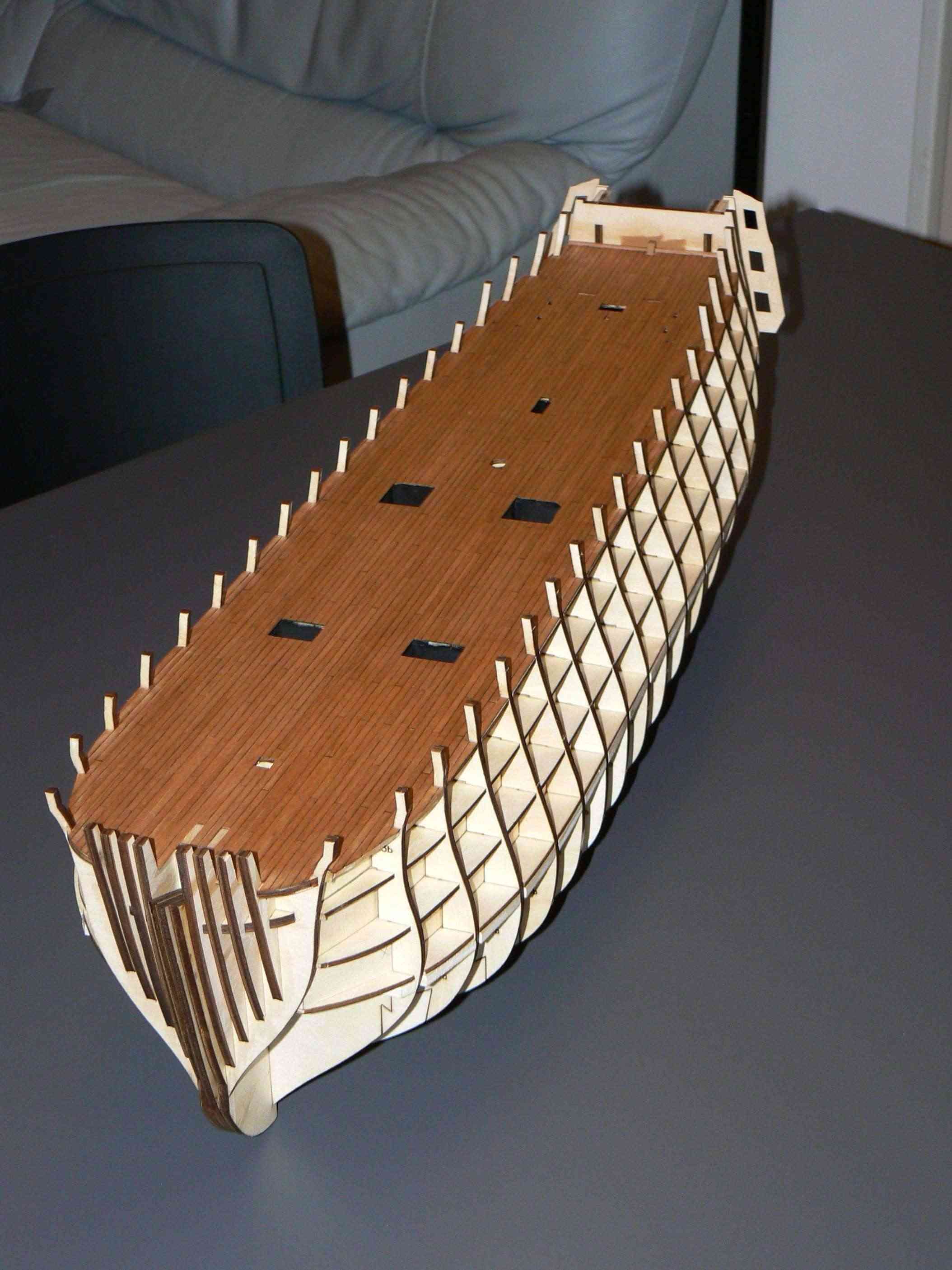
Wednesday, August 7, 2013Yes I know, I'm turning around to the real matter waiting for more favorable weather but simply I cannot apply myself too much in these days of heat . .Having finished the deck, having refined the deck openings, having painted the hull in black where required, there are now no excuses: I need to take on hands sandpaper and level the bulkheads, and then start to apply planks.But before beginning to bevel the bulkheads I decided to reinforce some weak points of the hull where it takes less than a second to break them . . with relevant consequences.So I reinforced the "scalmotti" (again I don't know the right english term) by fixing in their inner side a 5 x 2 strip. I used the cyano-acrylate. I used this kind of glue because when I'll need to remove this reinforcement I will be able to get successful quite easily with a simple cutter blade. Subsequently I fixed another strip sideways to the first to obtain a double reinforcement (5 x 4).The photos here below show the whole.Now I have no more excuses: . . . beveling and planking are the next unavoidable steps . . but only when there will be more acceptable temperatures.01
 02
02 03
03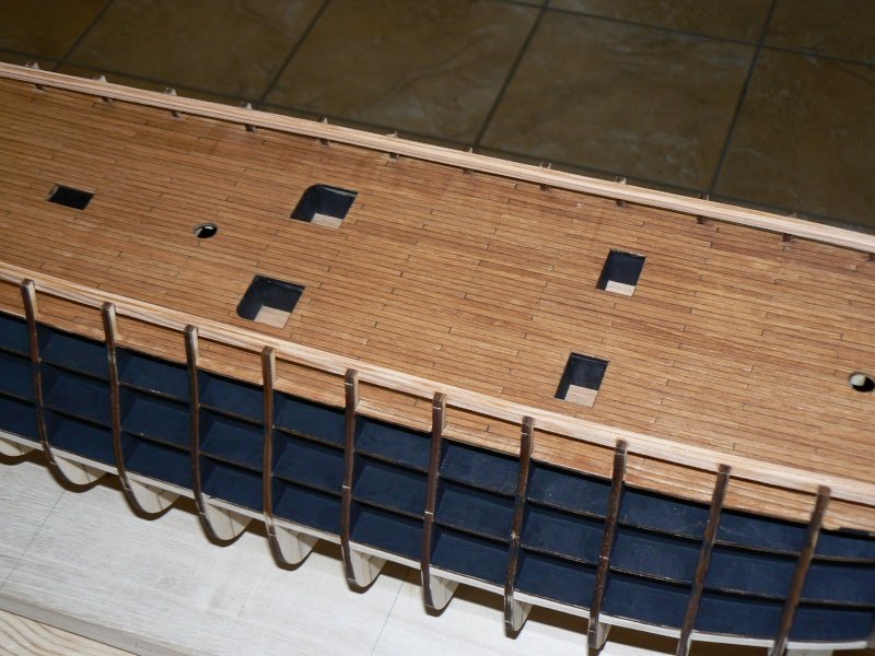 04
04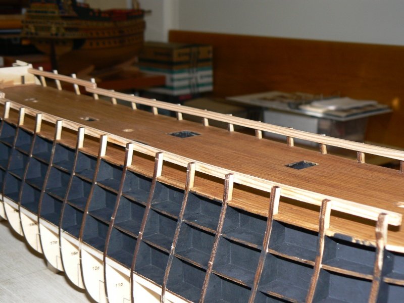 High Definition Images:Though my interest, I can not follow your build through your photos.
I don't know why they aren't opened...
ashiponthehorizon, I hope you are now successful in opening the images . . You really are the first to report me this kind of problem. Jack.
-
A couple of photos taken in daylight, giving a more realistic representation of the deck color.Cheers, Jack.01
 02
02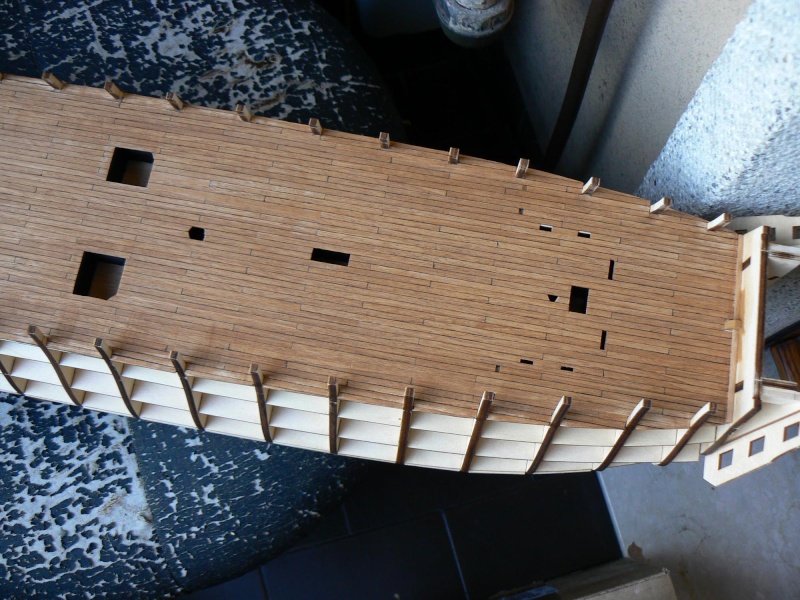 High Resolution Images:
-
Tuesday, October 2, 2012 - Display case . . continuation
The presentation of my work for the building of the display case base for my Soleil Royal continues here. In this new post I want to focus on a particular detail: the name of the model.
Usually a model is presented with somewhere a label that specifies the name and more. For my Soleil I used my computer and I tried a bit of presentations and I decided to adopt the label here below presented.
01 P1080382.jpg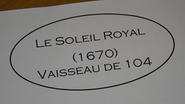
Having made my choice I passed to the practical realization and I designed the oval on an ordinary tablet of plywood, with a jig saw I proceeded to cut them and finishing with sandpaper and three coats of white acrylic paint as a primer.
A little trick that I have thought to work faster with acrylics: to have the paint drying in a couple of minutes, in order to avoid waiting for the complete "natural" drying, I use to heat the painted piece with the hair dryer . In this way I was able to apply three coats in less than 15 minutes against at least 6-8 hours of the normal procedure. In the picture 02 the resulting pieces, suitably sanded and ready for final processing.
02 P1080381.jpg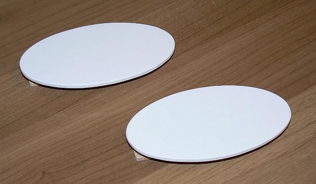
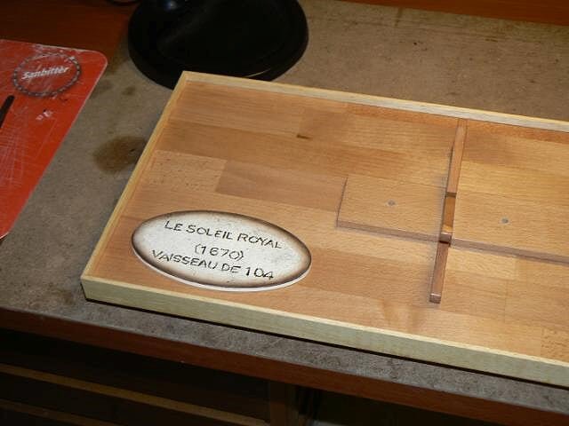
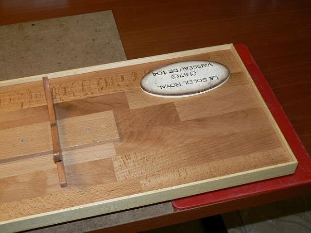
I left the final processing to my wife who loves painting with acrylics with the so called "country" style. And here below the result of her work.
03 P1080393.jpg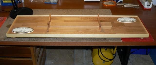
04 P1080391.jpg
05 P1080392.jpg
The pedestal in the center of the base is only positioned because I have to finish the screws and washers that will be used to secure it to the base. But this is a trivial detail. Until next time, Jack. -
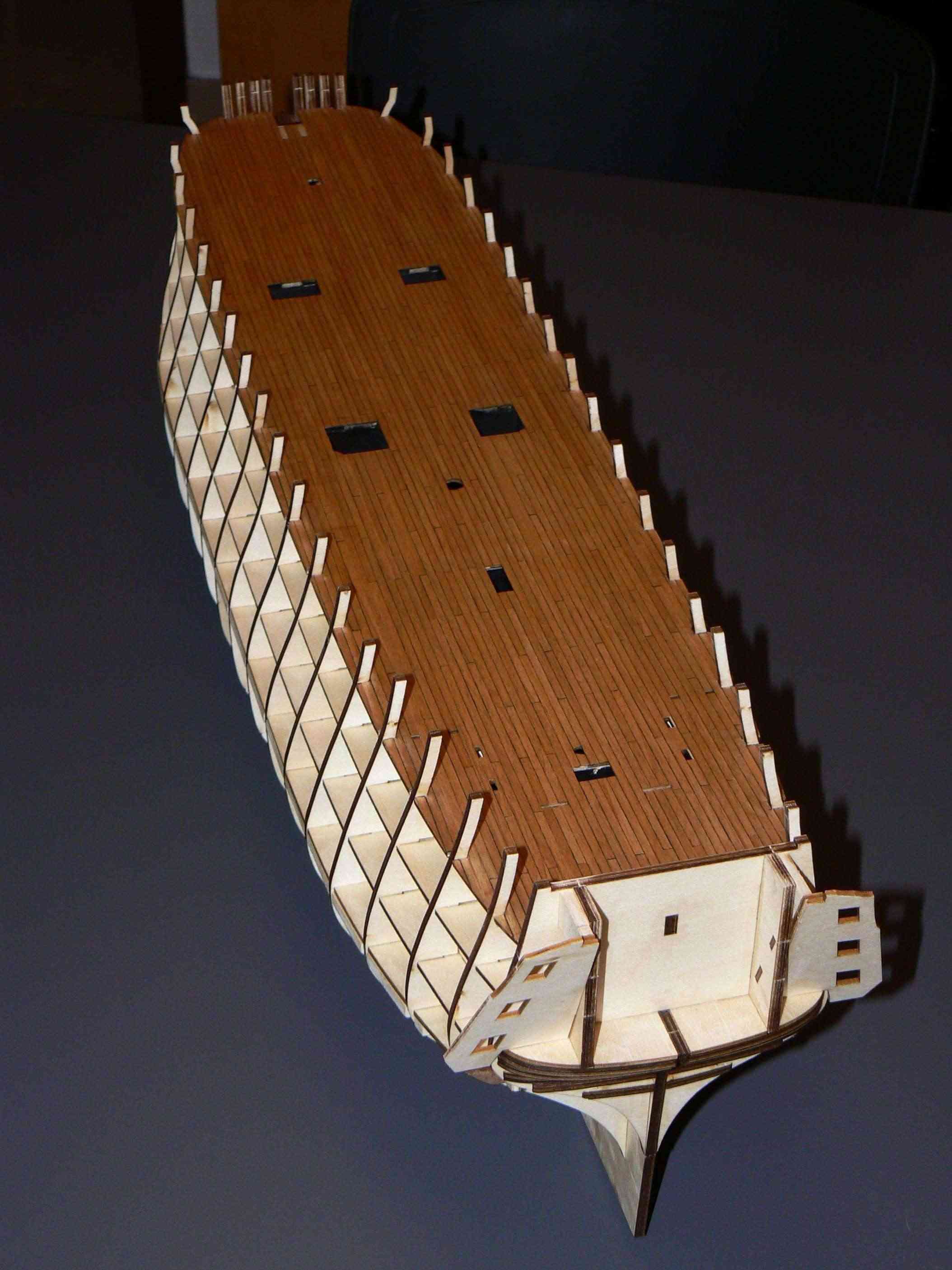
Thursday, August 1, 2013 - Deck planking almost finishedYesterday afternoon I 95% finished the deck planking. Today that glues is totally dry I proceeded to smooth with sandpaper (intermediate grain and subsequently finer) all the strips of the deck, to remove glue in excess and to level the whole. Needed some time and patience. . but still nothing if compared to what is coming for the hull.Then I proceeded to apply a generous coat of wood oil. The color became almost immediately warmer and appealing even if what you can see in the pictures here is not the exact color due to the use of the camera flash. I have to wait until next morning to take daylight pictures outside . . but I can not tomorrow . . it will be a task for Saturday. .I still have to refine the deck openings for the lower floors e masts partially covered by planks. And aft there is a small piece, covering the bowsprit, still uninstalled.After long days of hot weather with impossibility to dedicate my time to shipmodeling i'm too eager to show something . .01
 02
02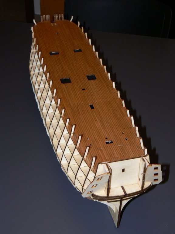 03
03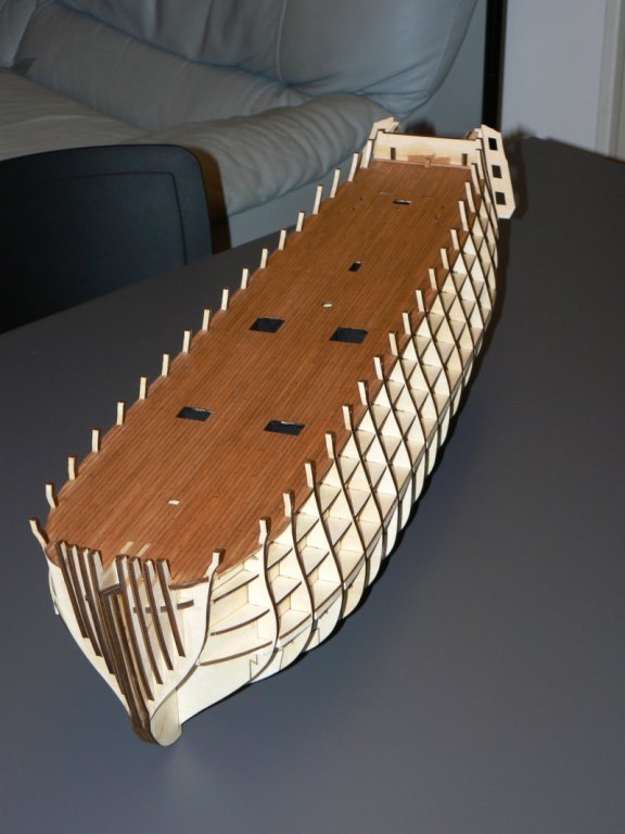 Cheers, Jack.AubreyHigh Resolution Images:
- riverboat and lamarvalley
-
 2
2
-
Perfection...Perfection Jack. Great work.
Yves
Thank you, Yves, for your comment . . Jack.,
-
Monday, October 1, 2012 - Display Case
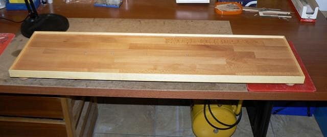
In these days since my last post I continued the work on the display case. For the base I bought at the nearest woodstore the three elements that characterize it, namely:
1) - a beech table (thickness 18mm) cut with dimensions of 99 x 27 cm; the customized cutting service was provided by the woodstore staff;
2) - strips of wood (unidentified), length 240 cm, 3 cm x 0.5; it will be used for the outer frame of the base;
3) - 5 knobs of lathed wood for the "legs" of the base.
The pictures 01 and 02 show the upper part of the base, with the outer frame applied. As can be observed the frame delimits the perimeter of the base and, being higher than 1.2 cm. will serve to hold the plexiglass of the transparent element of the case.
The wood was then treated with a coat of wood filler. Once the paint dried I sanded everything with very fine steel wool and then I applied a couple of coats of wood oil, the same I usually use for the model. Between one coat and the other I had to wait a couple of days to allow the oil to deeply penetrate and dry.
01 P1080388.jpg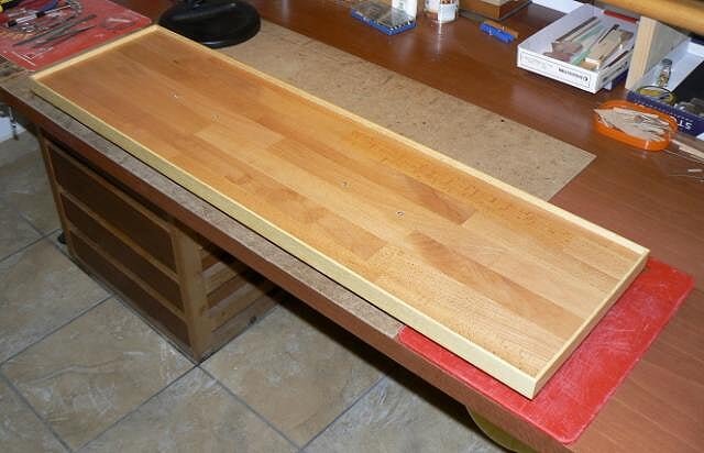
02 P1080389.jpg
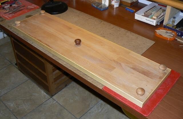
In the next two images (03 and 04) I show the bottom of the base, which is also treated with a coat of wood filler. Here are visible the five knobs that have the function of "legs". I decided it was necessary a fifth knob placed in the centre to avoid a possible failure in the central area of the base under the weight of the parts above. Unfortunately for this knob I had to use a different color because the light ones were finished, but it is well hidden under the base and should not be visible.
03 P1080383.jpg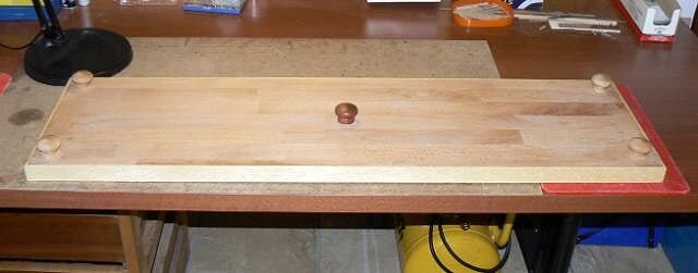
04 P1080385.jpg
Finally, the last image, even if these details are also visible in the first two (but in high resolution) where you see the threaded cylinders where I will fix the pedestal shown in the previous message. Anchor points are in number of four.
05 P1080390.jpg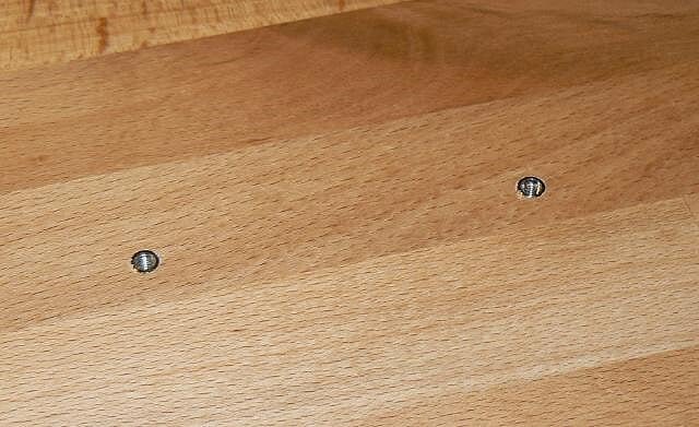
That's all for now, even though I have more pictures to show, but in the next episode. .
Cheers, Jack. -
Tuesday, September 25, 2012 - Display Case
I temporarily abandoned the stern and his goddamn decorations and I got into the building of the display case basement. A kind of digression to the routine of the stern. .
In the picture 01 you can see the first part of the case, the pedestal, just finished, even if they miss the obvious finish (stain, velvet or cork on the surface of contact with the hull, etc.). This piece will be later mounted on the basis of the case, not yet ready.
01 P1080380R_zpsfb8ce24c.jpg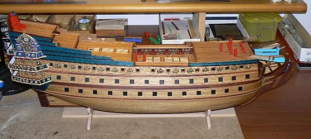
The next two images show this piece without the hull above, visible in all its details. If you look at the images in high resolution you will notice how the two supports, with a thickness of 1 cm. have been shaped with a camber to follow the lines of the hull in the area where it will rest. The material used is beechwood.
02 P1080377R_zps694ae4ec.jpg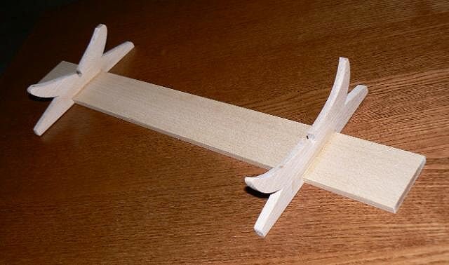
03 P1080379R_zps5aa91f5e.jpg
To take the shape of the hull in the area where this would be resting on the pedestal I used a tool that is called "form tracer", illustrated below.
04 P1080373R_zps71fd0ceb.jpg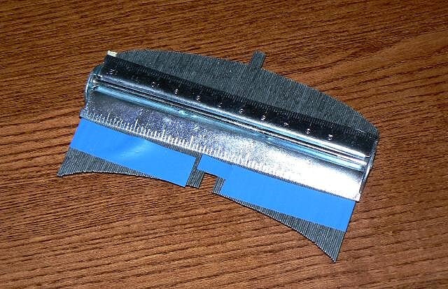
And before to work on the final beechwood table I made the prototype with an more ordinary poplar plywood 5 mm thick, much easier to work.
05 P1080374_zps4e0561c5.jpg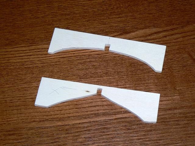
That's all for today, Jack.Aubrey -
Wednesday, September 19, 2012
The last evolution of the stern.
01 P1080367.jpg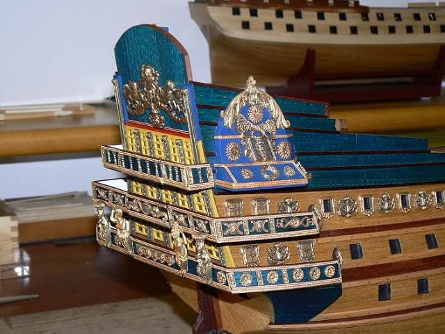
02 P1080370.jpg
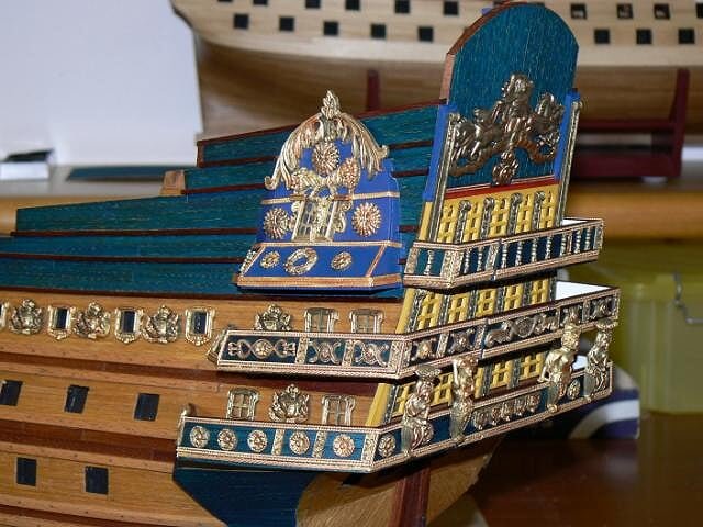
03 P1080368.jpg
04 P1080371.jpg
Then yesterday I took the hull and I fixed rigidly on the work table upside down to start thinking seriously about the decorations that are under the lower gallery and those to be placed on the two lower smaller bottles.
I must now say that the decorations of the lower bottles do not fit very well on their surface and, by a careful examination and after various positioning tests, this is a quite big problem . . I'm still far from a clear idea of how to proceed . . I'm considering to rebuild totally them with mouldings like FIMO or Milliput . .
Kind regards, Jack.Aubrey. -
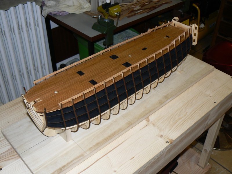
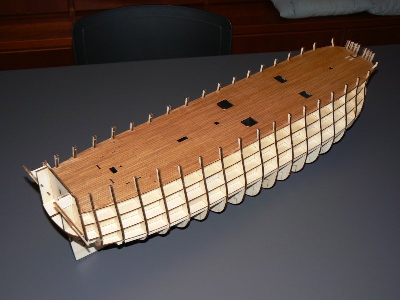
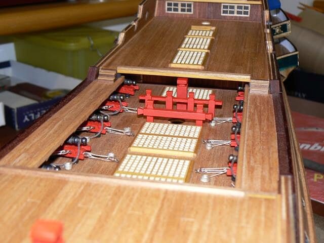
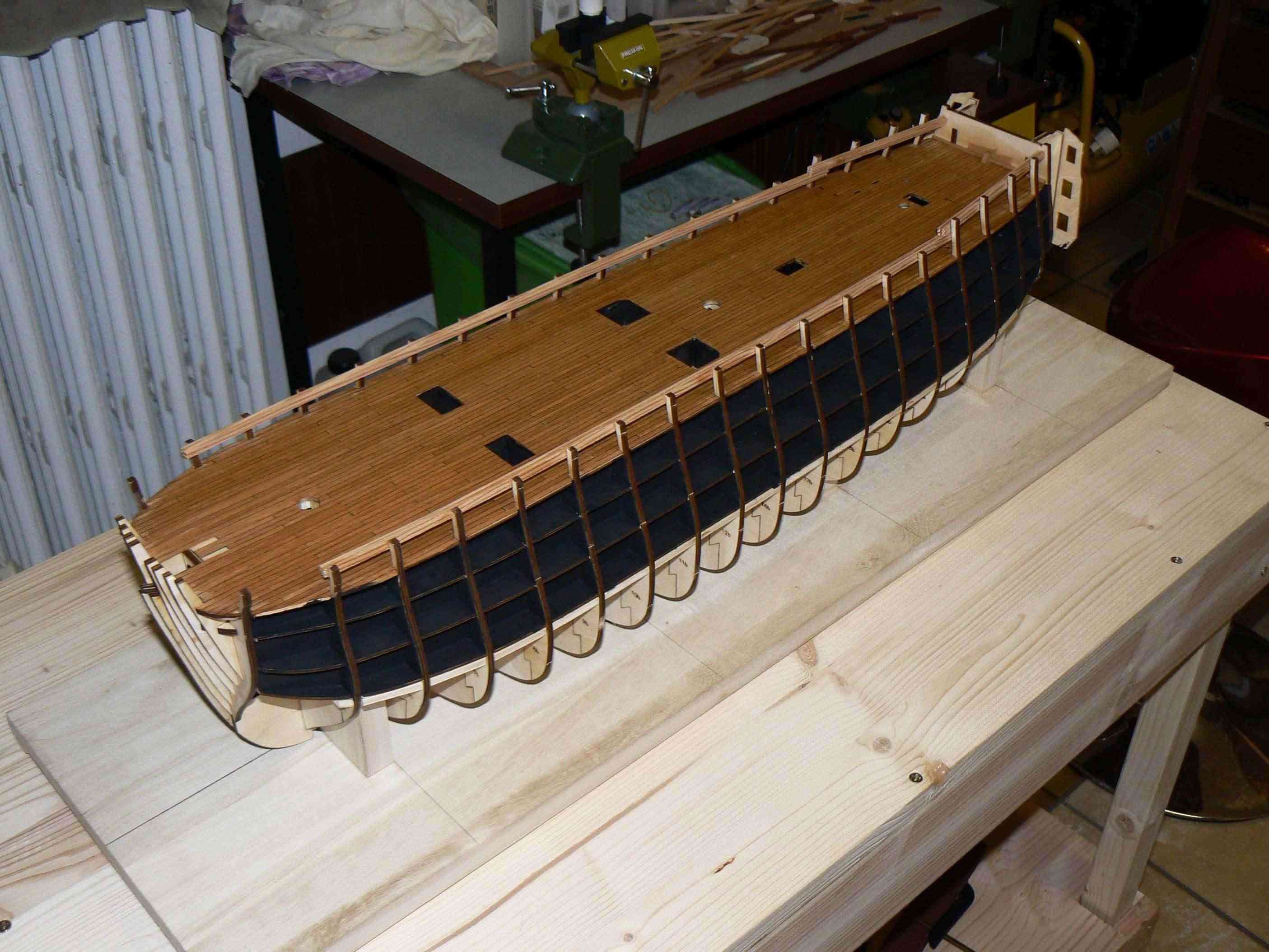
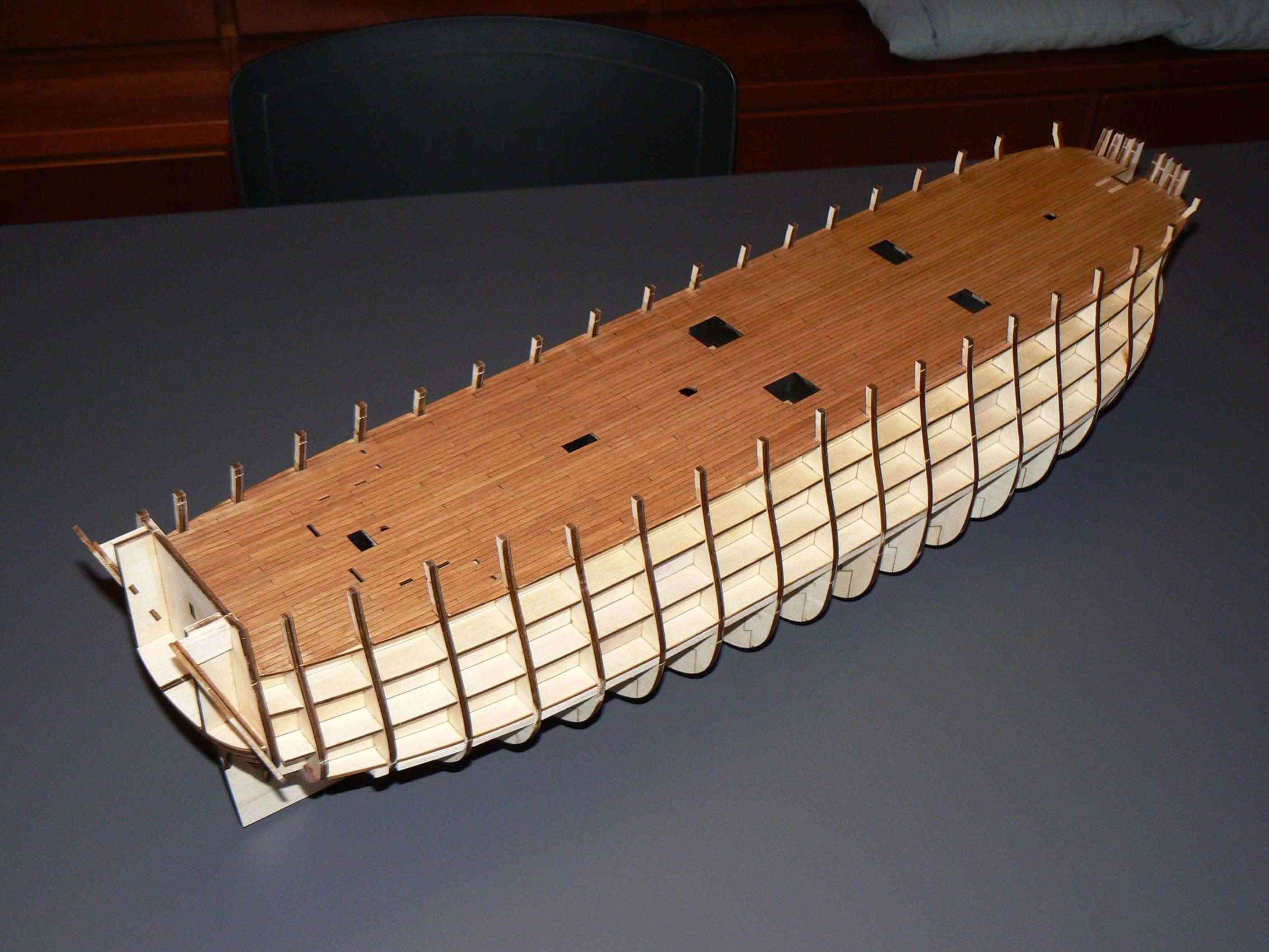
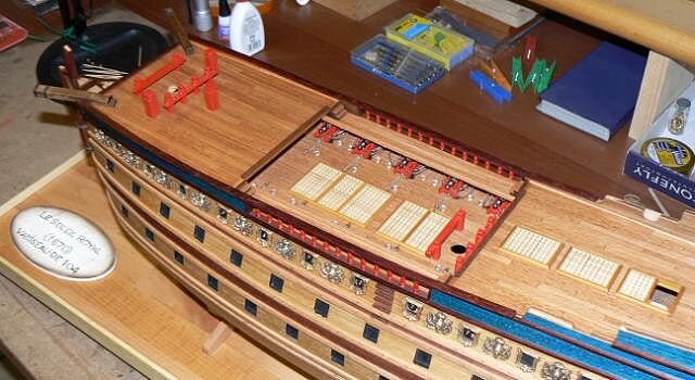
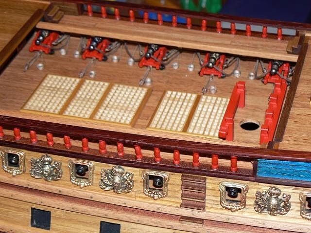
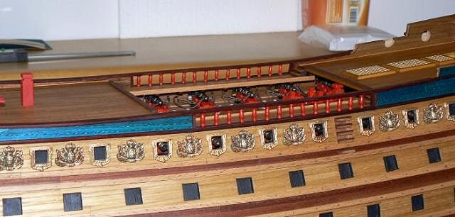
Tuesday, July 16, 2013 - Deck plankingToday I continued to apply the deck planks until I completed the stock of "ready to use" strips. Then I prepared another group of strips to be able to continue tomorrow.01
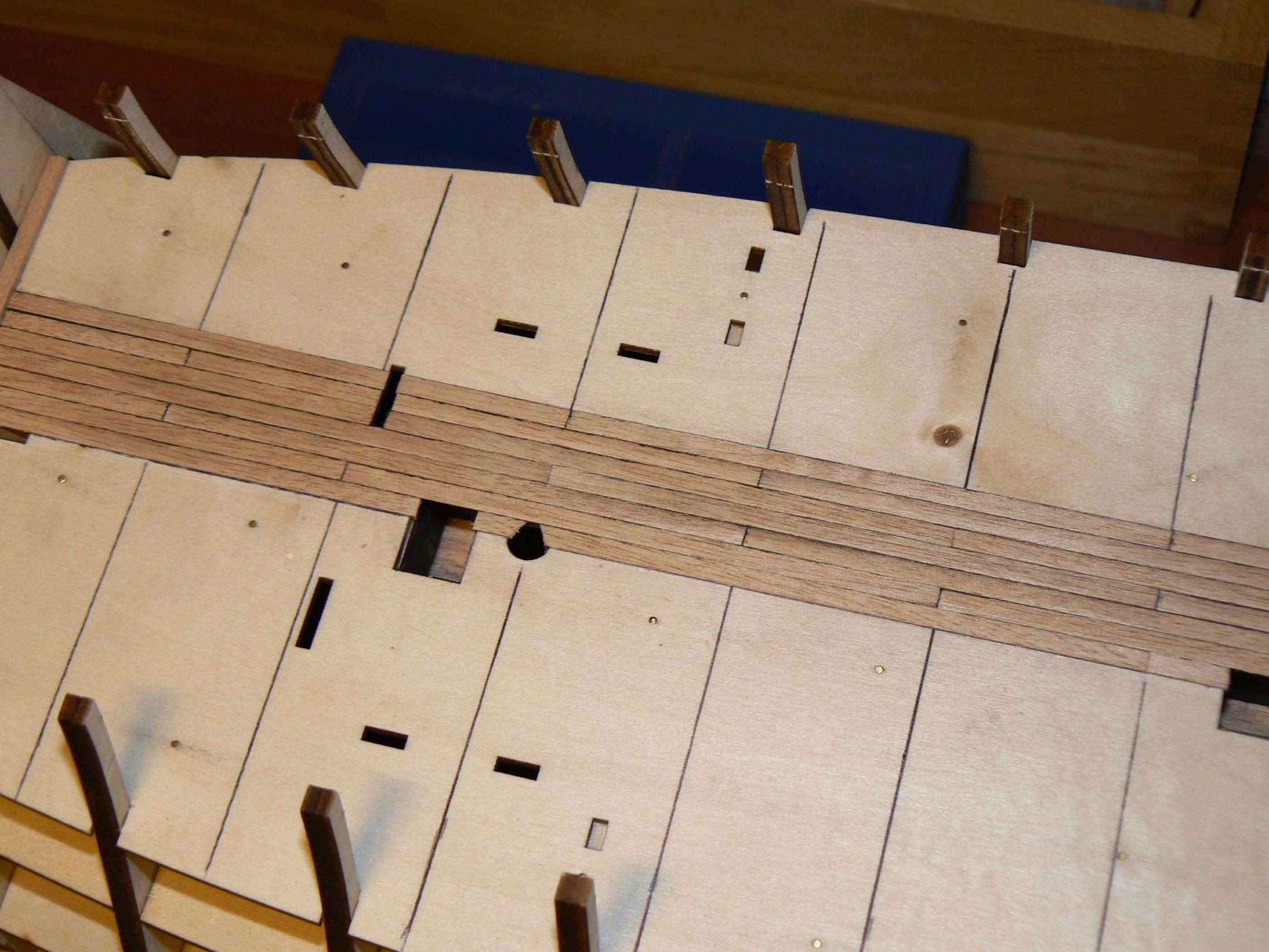
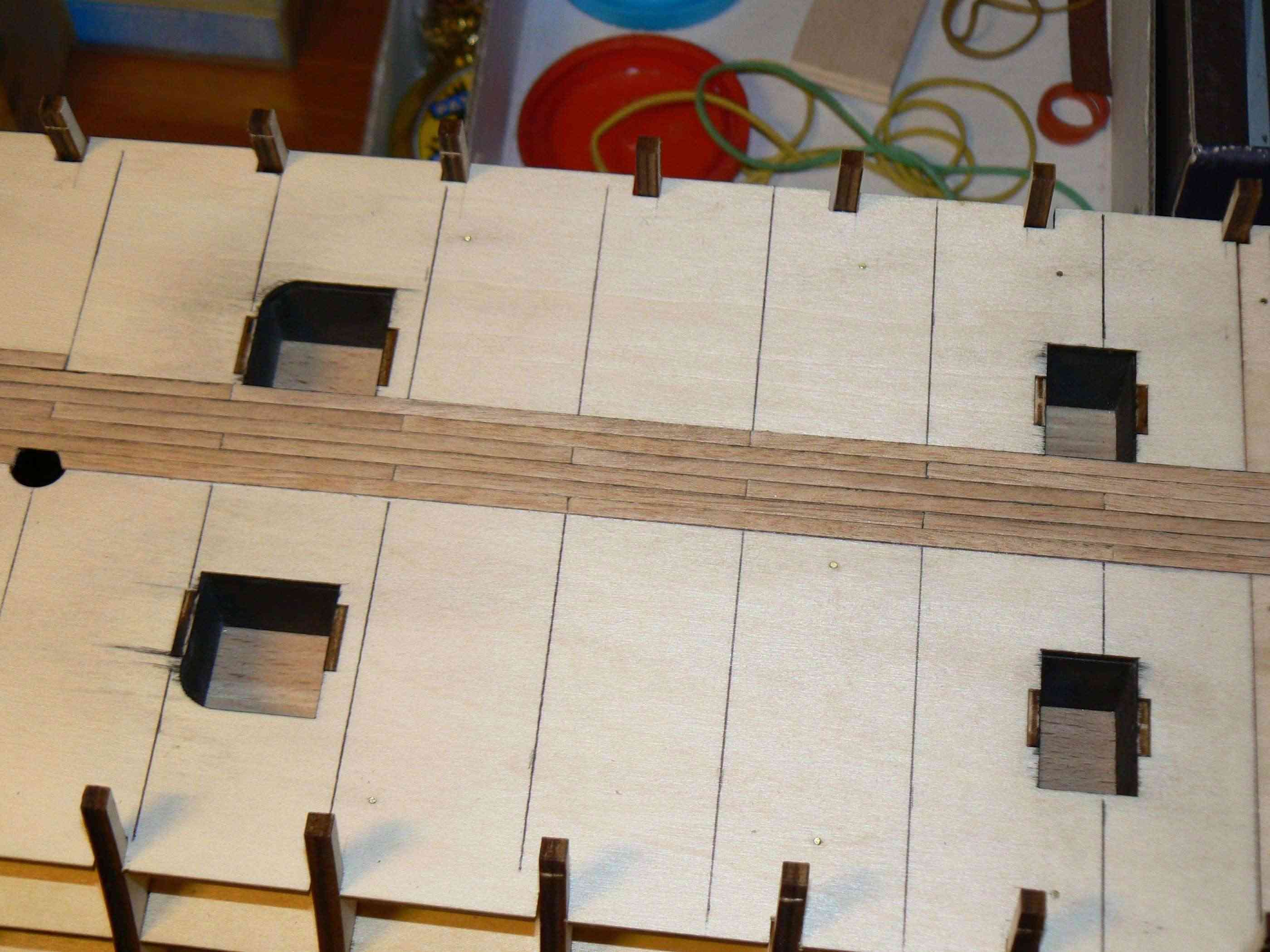
 I would like to report here a problem in the prow zone. As you can see from the next image the reinforcements applied to the first bulkhead, where it joins the deck, do not follow the "sheer" of the latter thus forming a kind of bump when you apply above the plank. I do not think I've made mistakes and so I think that here there is a small error in the project on the shape of the reinforcements.However, I don't worry too much: once the deck will be totally planked the bump will be less visible. I saw also that in this area there will be a couple of guns that should help to additionally hide this problem.02
 Cheers, Jack.AubreyHigh Resolution Images:
-
Monday, September 3, 2012
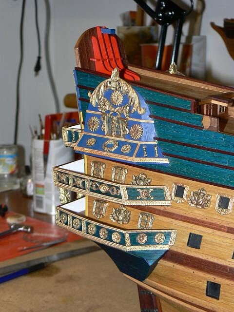
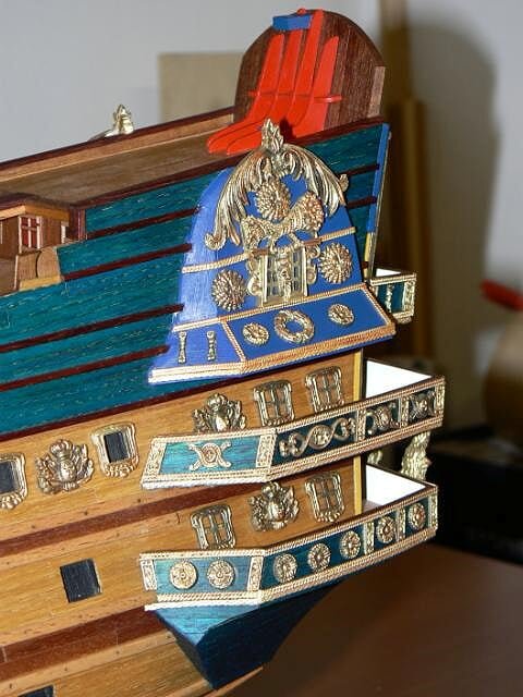
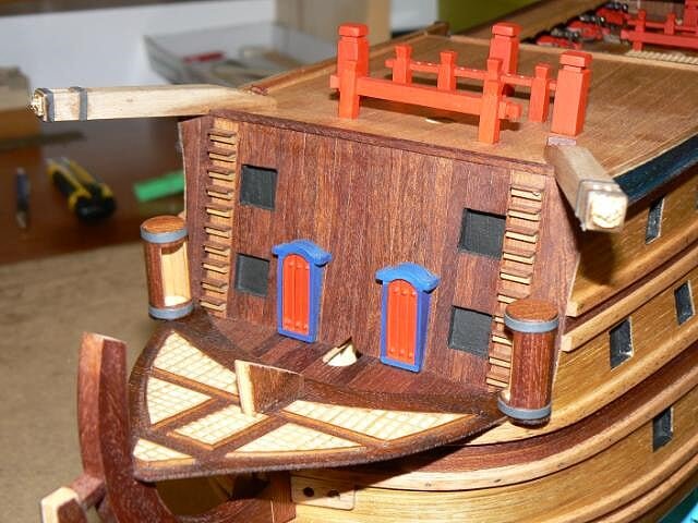
In the few hours that I devoted to the model in these last days I continued to apply some of the decorations that were ready for installation and, above all, I have finished the "missing wood pieces" of the lower "bottle". I also decided to change its color, applying the stained blue strips, as you can see from the first and second picture when compared to the previous already posted some time ago.
01 P1080357.jpg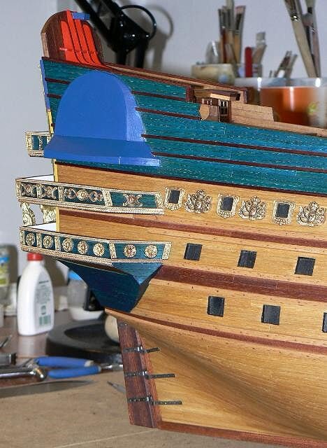
02 P1080358.jpg
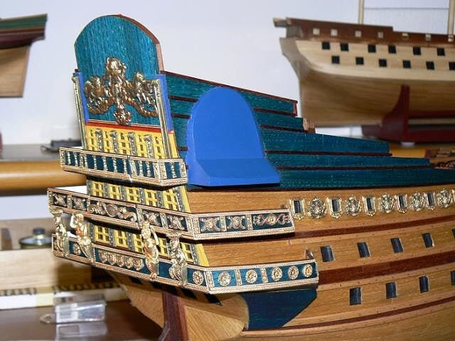
The remaining images show the other decorations applied to the gunports of the upper deck and bow. Nothing to add apart I used the epoxy glue to fix them.
03 P1080359.jpg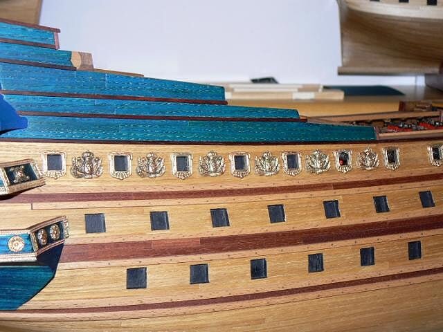
04 P1080361.jpg
05 P1080360.jpg
Kind regards, Jack. -
A set of more focused photos of some details. . the first still on decorations
01 Senzatitolo-1-1.jpg
02 Senzatitolo-2-1.jpg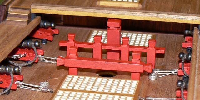
03 Senzatitolo-3-1.jpg
-
August 25, 2012. . continuation. .
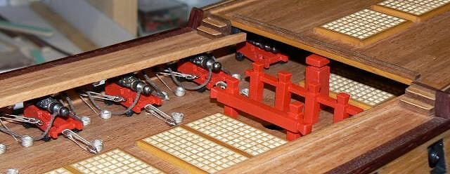
Some new details added on the decks: the pinrails of the mainmast. In the rush to fix these pieces I forgot to drill the pinrails before installation. Now I'll have to do it "freehand" on the pieces already fixed and will be more difficult to achieve the same spacing and alignment I would achieve before . .
01 P1080347.jpg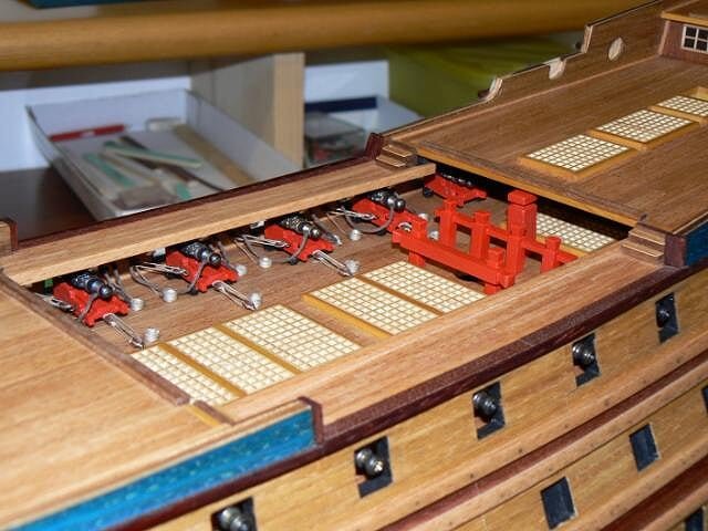
02 P1080348.jpg
Here are shown the WCs installed at prow . .
03 P1080349.jpg
Finally an overview of the guns after I finally glued the barrels to the carriages, using epoxy glue. Initially these barrels were fixed with the cyan and had fallen off completely after few time. The seal of the epoxy is incredibly stronger than the cyan for this type of bonding.
To keep in mind for the future for when I will have to fix the remaining gun carriages to the decks. . with this glue it will no longer be necessary to use pins as reinforcements.
04 P1080353.jpg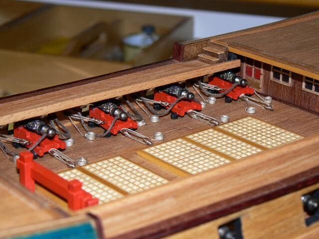
See you soon, Jack. -
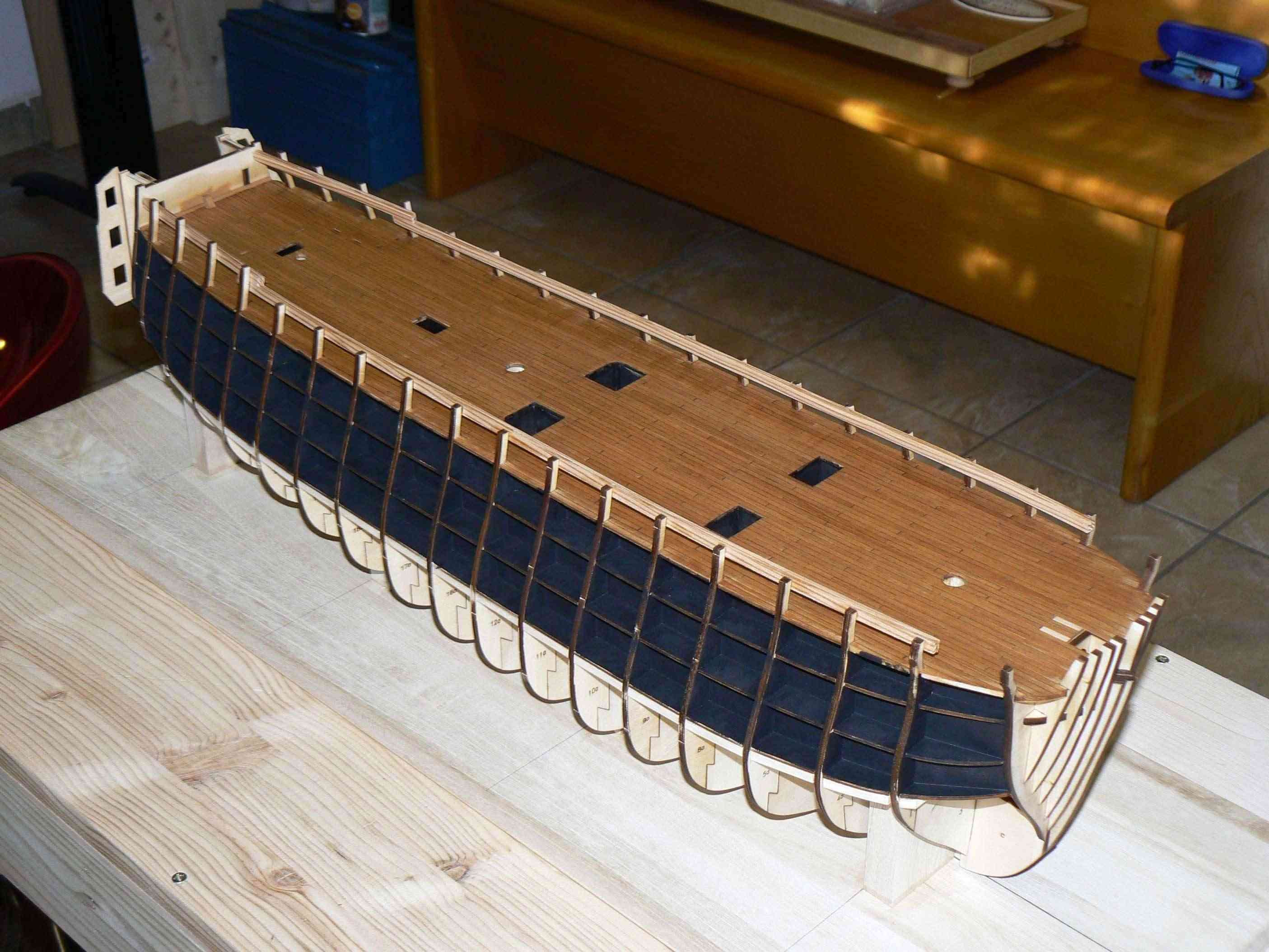
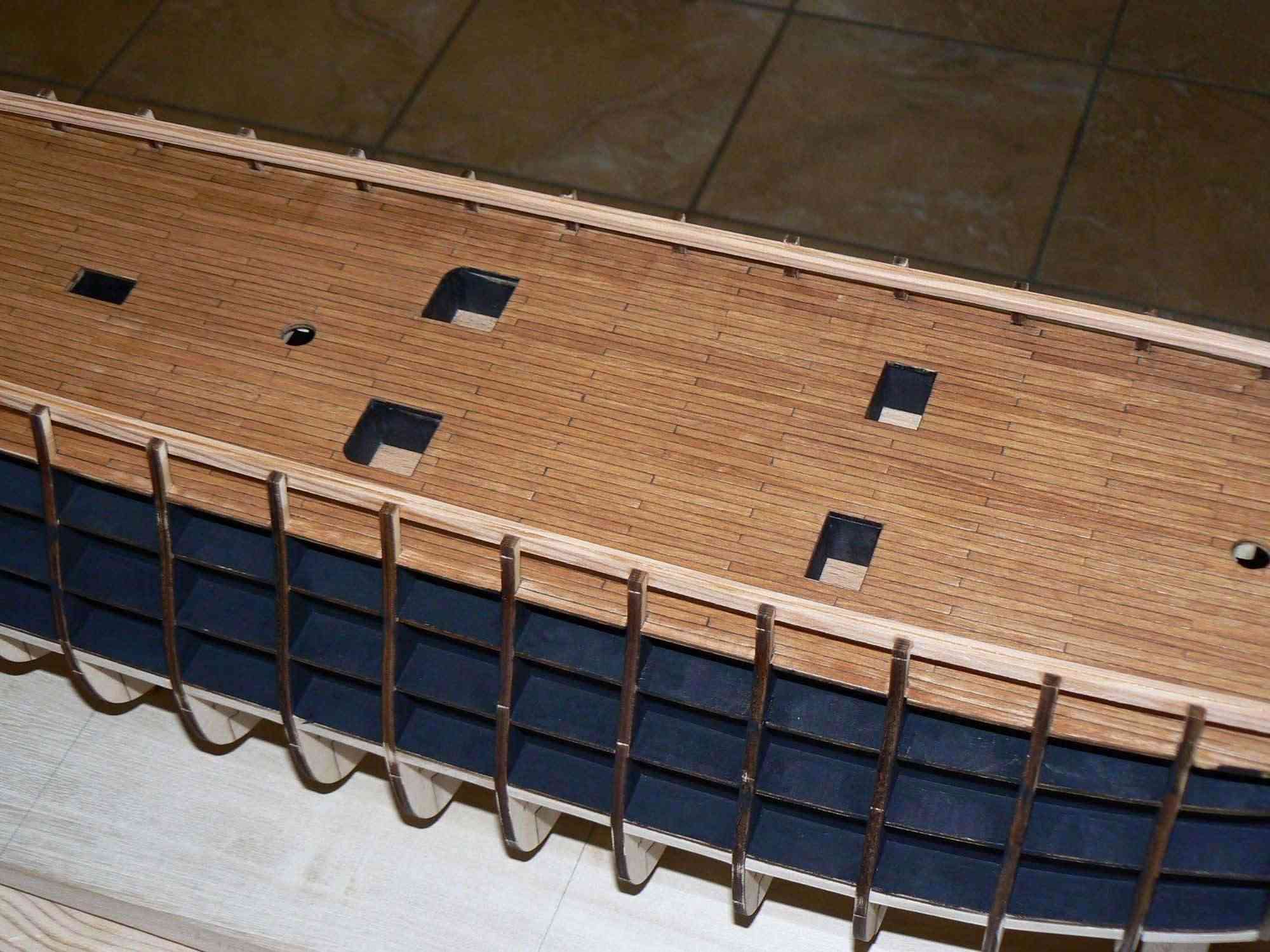
Saturday, July 13, 2013In the first picture a group of about thirty strips, prepared with the caulking simulation, still in the "clamp", after being colored with "dark brown" paint. Once extracted the planks must be divided one by one in order to be used.01
 I started the deck planking with the first group of strips I prepared a few days ago. Then I had to stop due to lack of material ready.02
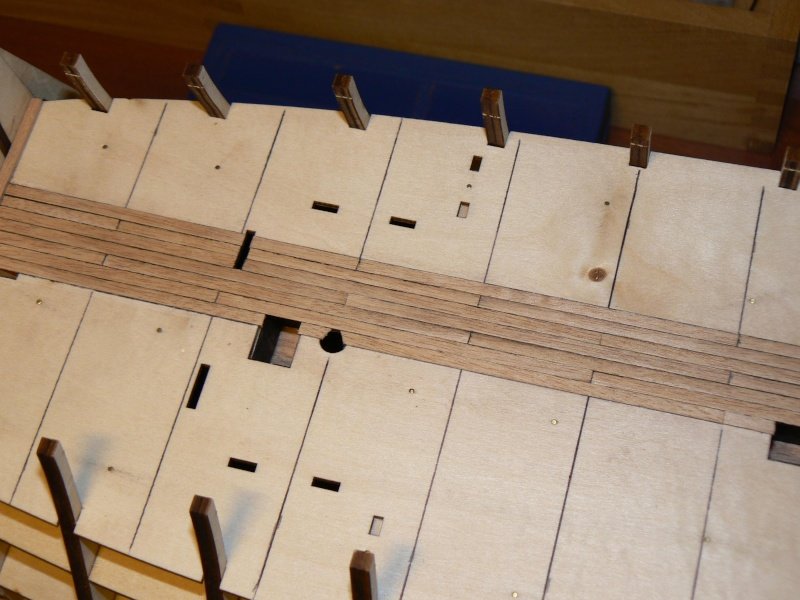 03
03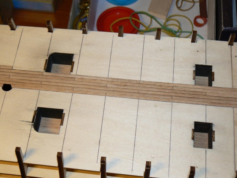 For the moment absolutely no problems; I will keep open the holes on the deck while planking is progressing, even if I think to refine them later.Sincerely, Jack.High Resolution Images:
-
. . continuation. .
I continue here with the publication of additional images of the stern galleries from a closer viewpoint. In the first one you may notice that I have yet to find a way to close the bottom "bottle" (I've not yet found a proper english term) on the front side, "closing" that I intend to do as soon as possible.
01 P1080350.jpg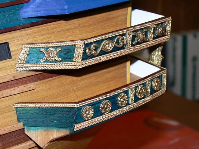
Here, however, you might notice a couple of caryatids that connects the lower to the middle gallery above. At the time of bonding two other caryatids are missing. They will be installed in place shortly. The two missing caryatids are visible in the picture number 04 at the top.
02 P1080351.jpg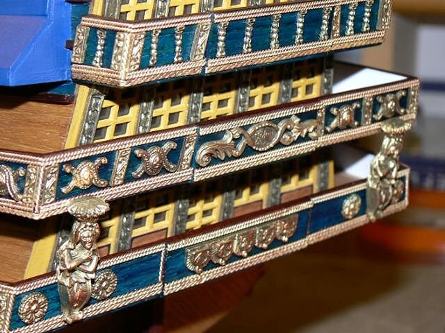
03 P1080352.jpg

In the next two images are shown all the last decorations, that remained to be gilded, in their last stage of processing. Now they have to be separated from the double-sided tape, smooth on the back side to remove the residuals of the tape glue and other filth in order to prepare a good support for bonding. Then it will be the turn of the "bottles" decorations . .
04 P1080354.jpg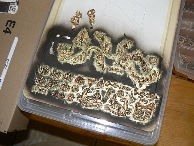
05 P1080355.jpg
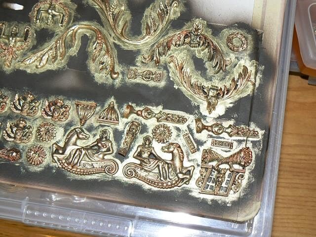
It remains to "gild" three statues, rather large: the figurehead and two human figures that are to be applied in the stern area. Having regard to the size I want to think not only to a process of browning but also to apply some color. To this end, I will try to find some photos on the internet "enlightening" of these details. Until now without great success but . .
See you soon, Jack. -
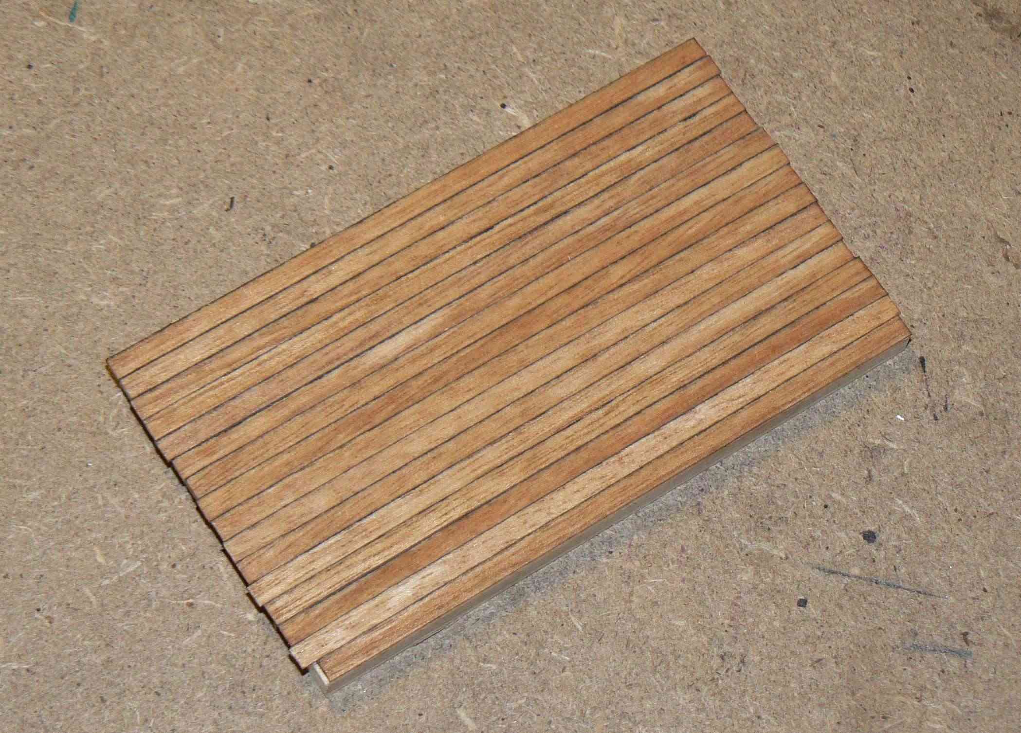
Tuesday, July 9, 2013 - Serious test for deck plankingThis afternoon I started by working on the Soleil Royal, but at some point I came to a standstill and I threw myself to perform a more serious simulation of the caulking of the 12 Apostles deck. I already discussed in the previous post why I came to this decision today, so I will not go back on it.First I want to show you the final result of the test, made on a plywood tablet (with size of 9 x 4 cm.). I decided to use strips of 9 cm. length. Slightly long as they would mean in the real world planks of 9 meters in length, while probably are more plausible strips of 6-7cm. . . . but I don't want to go crazy using pieces so small.The first photo was taken in my lab with the (photo)camera flash. .01
 The second is in natural light on my balcony. . the color is pretty much the same so let's say that is the real color. I forget to mention I treated this prototype with oil for wood.02
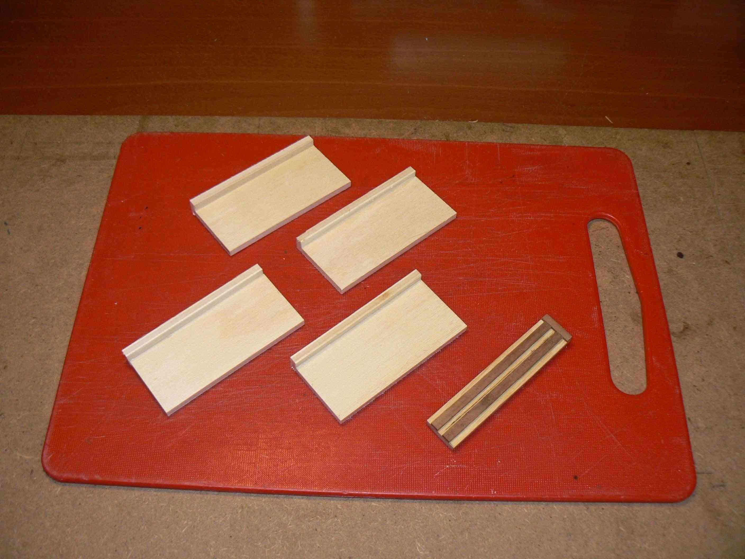
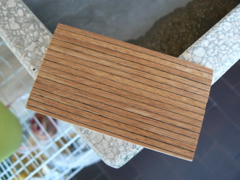 The test was not only designed to see the result but also to develop a method for massive preparation of all these 9 cm long planks. Below you see two pairs of containers for strips and the tool to cut all the strips at the same length.Use of the latter is intuitive: you insert the strip to be cut in the center slot, to the end. Then with a cutter cut the strip at the end without the latch. At the end they are all the same and you spend 2-4 seconds per piece.03
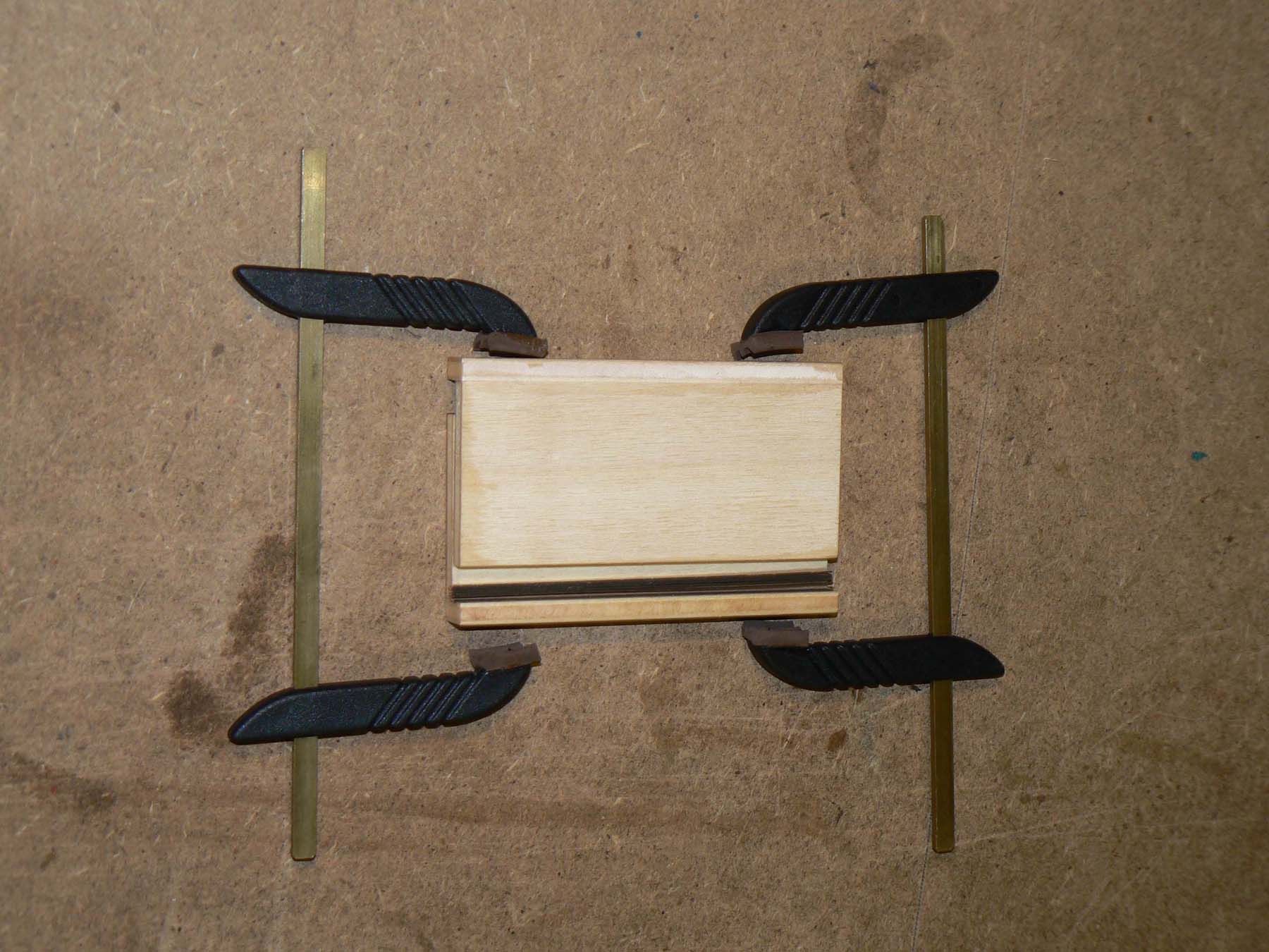
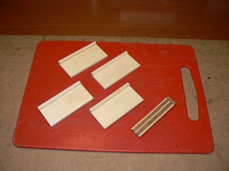 The use of the other tools is more complex: take thirty strips previously cut and put them side by side on one of the four tools shown; at this point position a second tool piece inverted and the whole is brought to forcing the strips side by side. Now you adjust the whole and you can also level them with sandpaper. Finally hold everything with clamps to keep firmly and pressed.At this point apply a coat, rather dry, of polyurethane black paint, speed up the paint drying process using a hot hair dryer . . and you have practicaly finished. Now you need to separate the planks and store them for usage.Simple though laborious, but the quality has a cost . .04
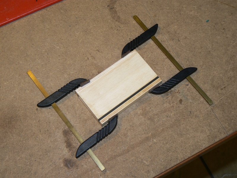 05
05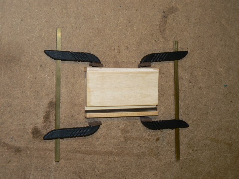 That's all for today, Jack.High Resolution Images:
-
Tuesday, July 9th, 2013Yesterday, during the weekly meeting between a group of modelers, I discussed with them about this problem, presenting my idea (which mine is not) to use the thread between planks.There was a modeller who had used this method for one of his models in 1:48 scale, and arguing with him, I discovered so many practical details that I definitely lost the enthusiasm for this solution.The problem lies in the strips (3 x 05mm) that are to be used that do not satisfy the needs to perform this processing. I will not explain why because it would make a treaty (which I do not want to write) but in the end I was convinced that this is a good solution only if strips of a certain thickness (ideal 1.5 mm) are used.Then, while we were in the meantime working collegially to mount a 12 Apostles, I did a couple of tests.The best solution was to put side by side a dozen strips (in this case, lengths of 6-8cm) kept well clamped together and apply a rather dry coat of polyurethane black paint instead of the usual graphite of a pencil.At the next test application on a tablet of plywood the result was pretty good. At this point it is likely I'll follow this way, except that I intend to repeat a more serious test and in addition I want to build a "tool" that allows me to hold tight to each other the strips during this delicate phase of staining.Sincerely, Jack.
Le Soleil Royal by jack.aubrey - FINISHED - De Agostini - Scale 1:70
in - Kit build logs for subjects built from 1501 - 1750
Posted · Edited by jack.aubrey
I decided to work on the gunwales above the third deck battery (waist), an activity that involves the use of the metal columns that I had previously colored red.
Obviously I was prepared myself teorically to manage this step and I came to the conclusion that:
For the second point it seems obvious to point out that once the whole composite was dried completely would have had the exact shape of one side of the waist and forecastle.
Due to the long drying time of the bi-component glue, I spent a day bonding all the columns on the waist while I spent the next day to apply the strip prepared in step 2, the columns are glued in turn to the top strip always with bi-component glue.
It was not a difficult job, the only real problem was caused by the same columns that, perhaps because of the molding process not very accurate, were not all exactly with the same height and then in some cases were too short and other too long.
With a lot of patience I leveled all the columns with the mini-drill, which was mounted on a grinding wheel suitable for metal.
Some adjustments to the bulwarks profile which lacked a few tenths in certain points and then I could proceed with the final bonding.
The third day was dedicated to finishing the job done and to complete some of the remaining two ship boats accessories (rudders, eye bolts, coils of rope, etc.), to install accessories today in order to have the boats "really" finished .
Below are some pictures of the work done.
01 P1080427.jpg
02 P1080428R.jpg
03 P1080429R.jpg
04 P1080432R.jpg
05 P1080433R.jpg
Cheers, Jack.Aubrey.