HOLIDAY DONATION DRIVE - SUPPORT MSW - DO YOUR PART TO KEEP THIS GREAT FORUM GOING! (Only 20 donations so far - C'mon guys!)
×


_SalD_
-
Posts
828 -
Joined
-
Last visited
Content Type
Profiles
Forums
Gallery
Events
Everything posted by _SalD_
-
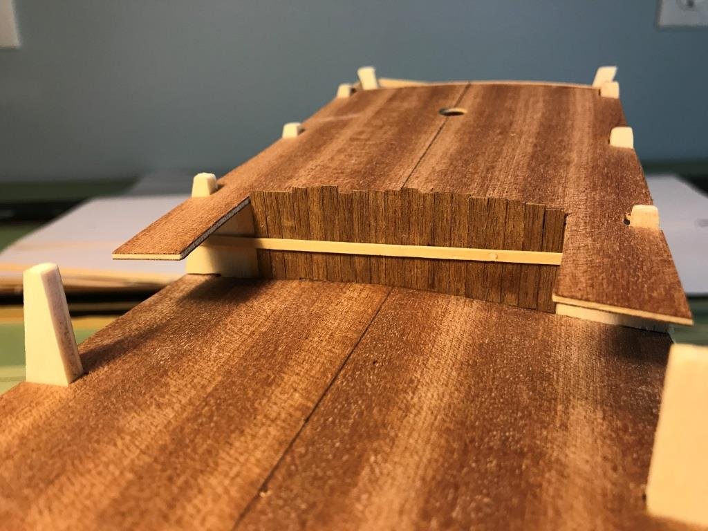
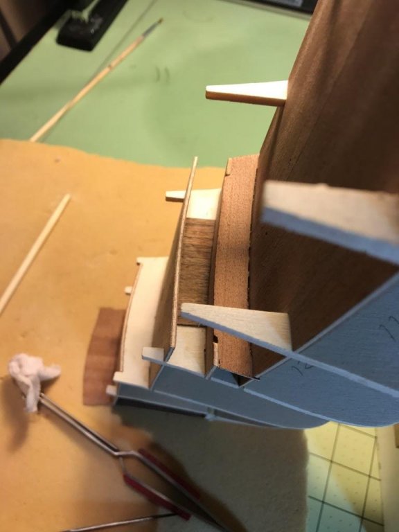
 I finally found the piece of planking I was looking for....the last piece. Prior to closing up the hull I like to add a little 'treasure' for anyone who might find it. The next step was to cut out and square up the gunports and then to sand and smooth the hull planks. Needed to use some wood filler at the bow. I'm happy for the most part with the way the first layer of planking came out. In hindsight I probably should have tapered the planks at the bow contrary to what the directions said that it wasn't required. I'll be out of town for a few weeks so the shipyard will be shutdown for a while.
.thumb.jpg.d7f482890f266faae162b6202ddc9eb3.jpg)
.thumb.jpg.d902359b88f19a4c5a9e1dbcffbaa62d.jpg)
.jpg.ea56025a2283c07f2f24695ae6080712.jpg)
.thumb.jpg.311a4aac2609c8891c47bdd58e9c52ee.jpg)
.thumb.jpg.7f252965340ed63c9974e843badfff8d.jpg)
.jpg.d5771ca90bcda3db520c38282ed65bbc.jpg)
-
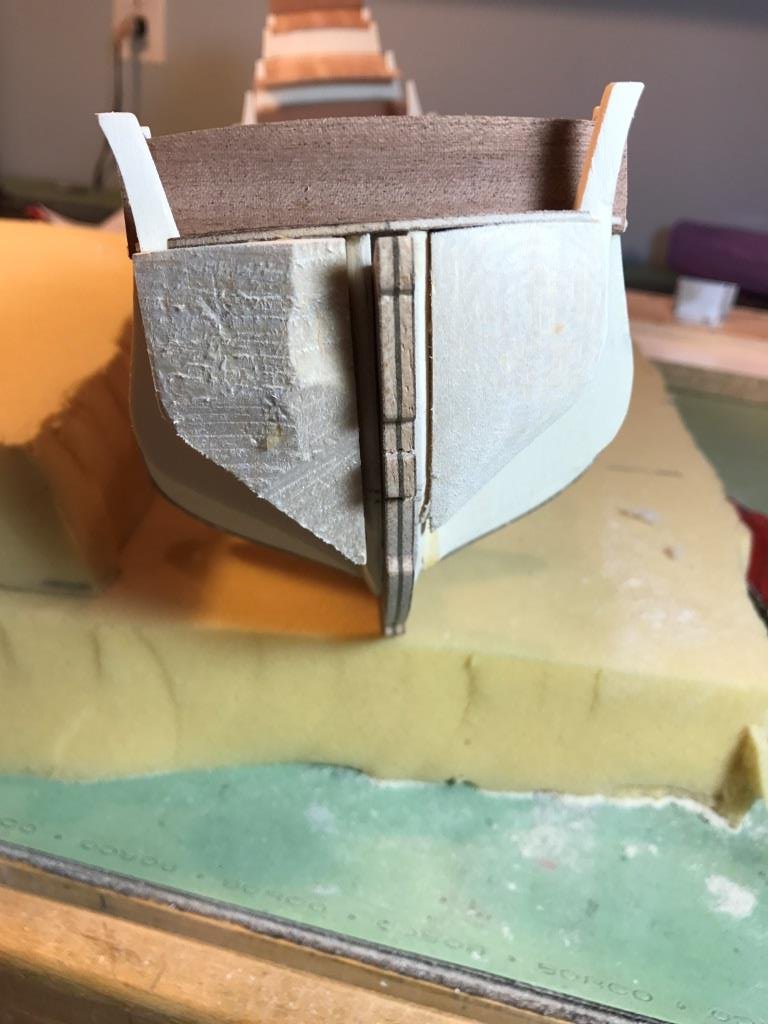
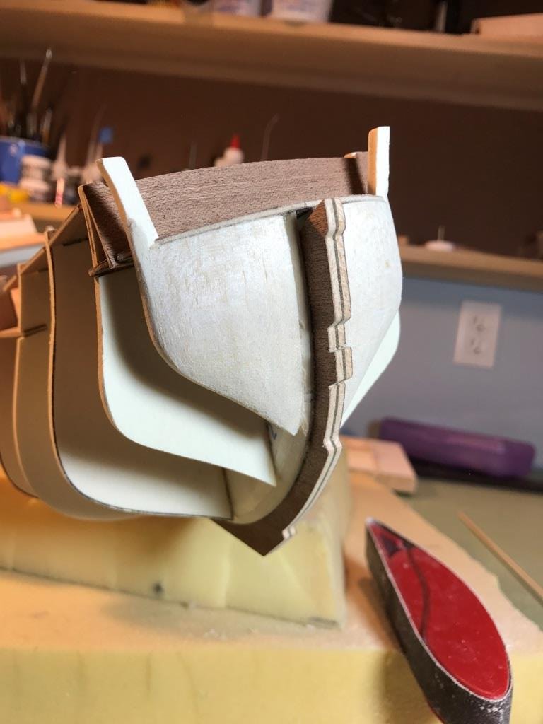
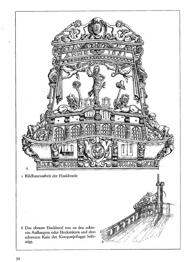
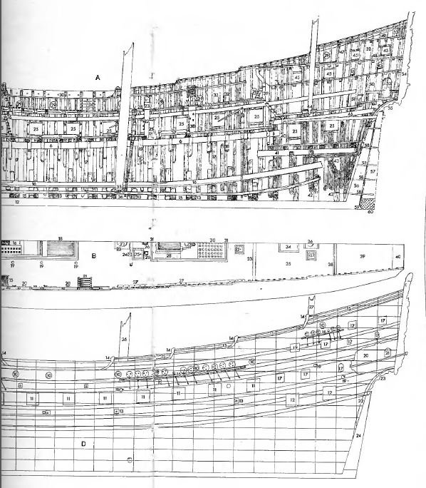
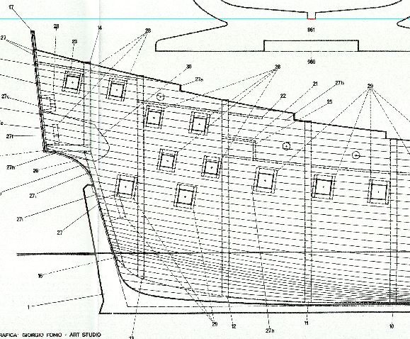
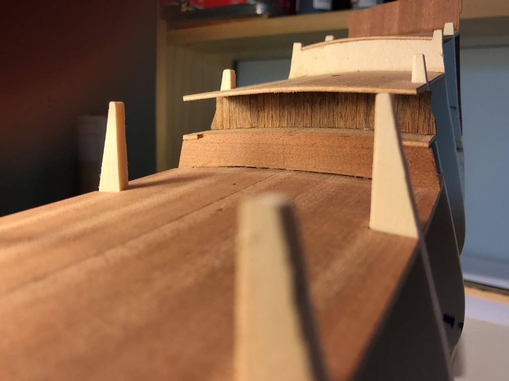
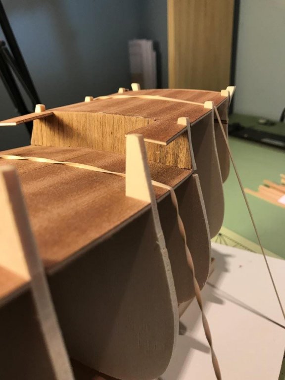
Continuing with the first layer of planking. Going slow but steady. I deviated a bit from the instructions on the planking placement and gunport openings. I've decided to place the planks in continuous pieces over the gunports and then go back and cut out the openings later. All the dummy gunports have been glued to the backside of the planks in their appropriate positions and marked on the exterior of the planking in order to cut them out. I'll let you know how this works out. The bow will need a little work to fill the gaps in the planking. I do have one question. The kit drawings show the gunports, more or less, perpendicular to the sheer of the ship. The gunports shown on the drawing from Herman Ketting's book shows them vertical. Although I personally like the looks of the ports that follow the sheer should they be vertical?
.jpg.282e9e2e29cc321b6bf014fd5c29cff6.jpg)
.jpg.715e4277257559bff3f2c7cbf5e1383f.jpg)
.jpg.78ad440c8bc1612dc49475dda8239f2d.jpg)
.jpg.5907aea832bce4fd29e23edebce0b41f.jpg)
-
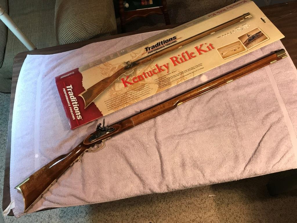
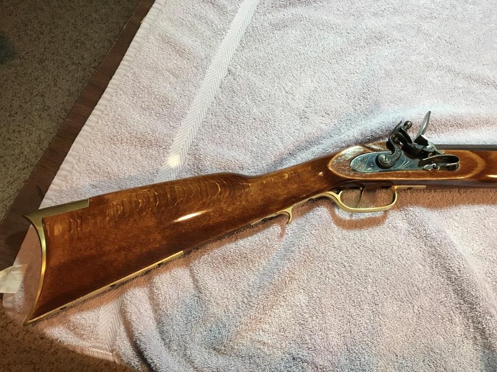
Yes it is although I have not tried it out yet. May fire it once or twice and then hang it on the wall.
-
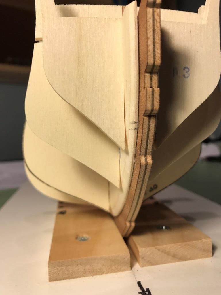
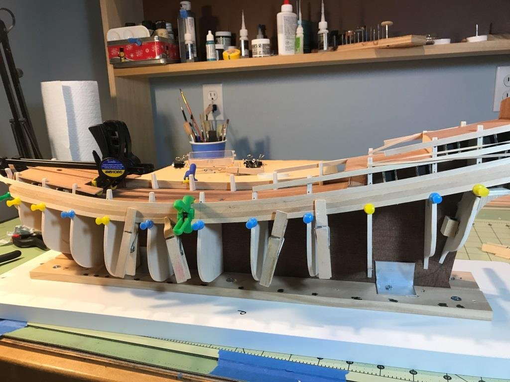
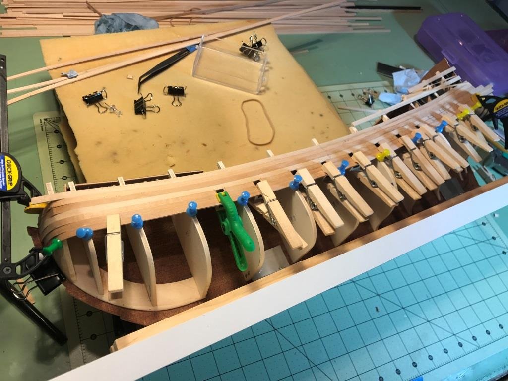
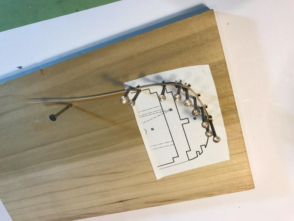
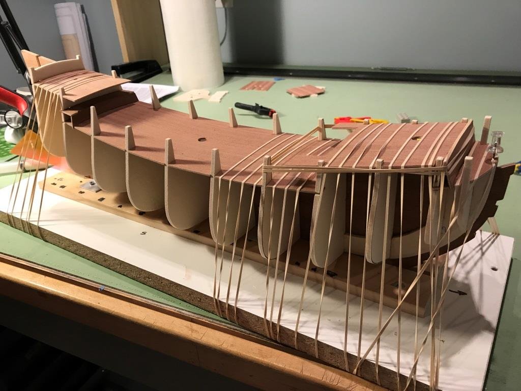
Sorry for the long period between posts but it’s been a busy summer. I finally started the first layer of planking and for the most part I have been following the procedure outlined in the manual for placing the planks and dummy gun ports behind them. I made a little jig to pre-bend the planks to fit the sharp bend at the bow. I used a hand held steamer to soften the wood as I bent them. I order to make it easier to glue the planks in place I pre-positioned the planking along the bulkheads after steaming them and allowed them to dry overnight.
-
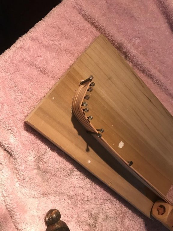
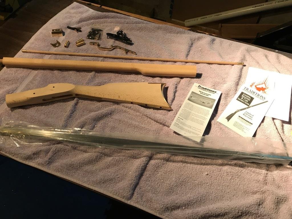
It's been a while since my last post but I've been working on my Father's Day's present that I treated myself to (it's always a good excuse for a new toy ). This is something I always wanted to try and it only took a few weeks. I won't go into a lot of detail just a few pictures. Started with this Finished product Now back to the ship.
-
Thanks Jay, and yes I refer to Jan's build quite often.
-
Jan thanks for the tips. That's a good idea to put tape on the exterior side of the upper bulkheads prior to planking. I was trying to think of a way to keep the planking from adhering to them so their removal would be easier.
-
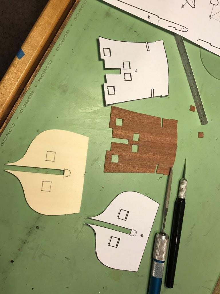
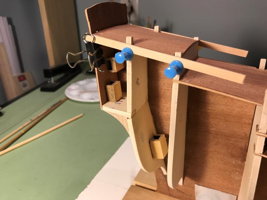
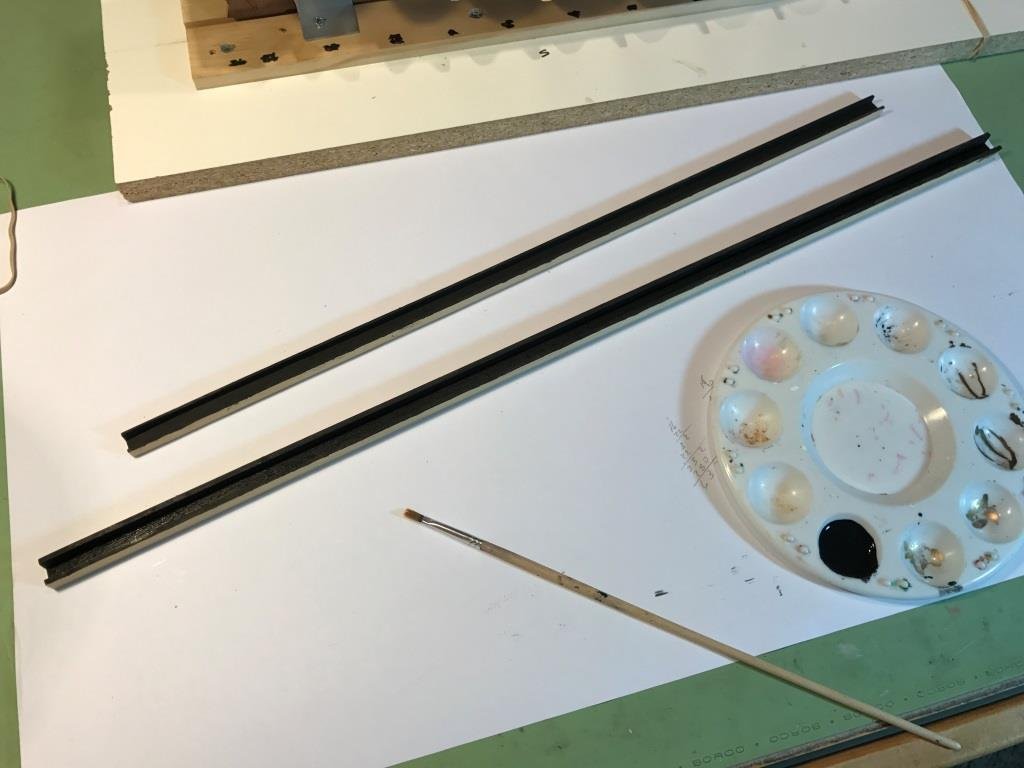
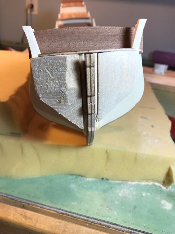
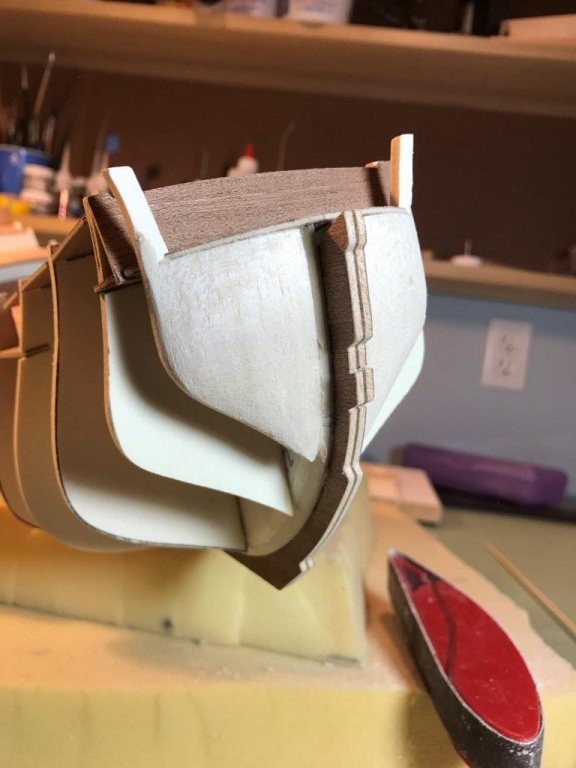
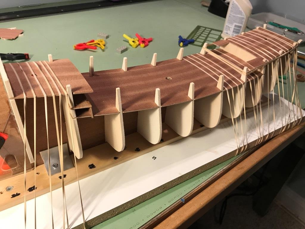
Started to do some prep work prior to starting the planking. There is channel shaped wood stock that is to be cut and used for the dummy cannon ports. These pieces are installed behind the first layer of planking as the hull is planked. The ports are to be painted black so I gave the strips a few coats of black paint prior to cutting them and then I will just touch them up once they're installed. The directions also say to pre-drill the back of the dummy ports for the installation of the dummy cannon half's prior to installing them. I was wondering if it would be better to drill them after they're glued in place otherwise how can I ensure that all the holes will be in the right place. The directions also recommended covering the #6 and #12 bulkheads above the decks prior to installing the hull planking. #12 bulkhead, rubber band helped keep the pieces in place while installing. #6 bulkhead, this one was a little challenging, did it with the ship vertical.
-
Jan, I had thought about cutting in a rabbet at the stern and bow to make installing the planking easier. I should have done it first thing prior to setting the bulkheads which would have made it a lot easier but I wasn't confident enough about cutting the rabbet in before I knew exactly where it was located. Why make it easy when complicated works just as well I do plan on painting the bling. As of right now I'm thinking of making them look weathered and not brand new.
-
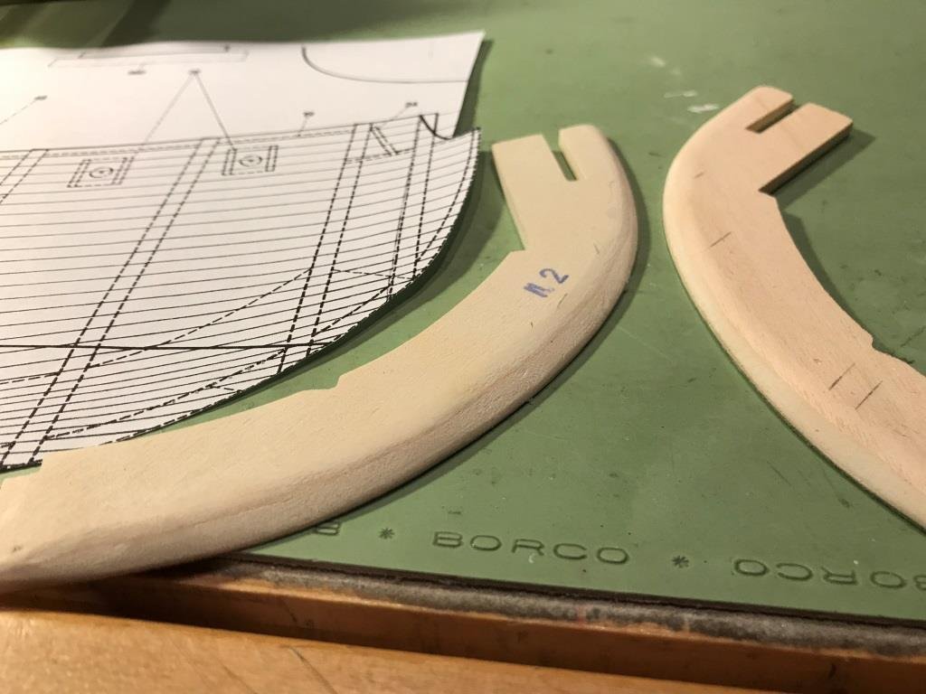
Duff thanks for the offer but I think I can use google to help with the translating Jay, the #2 fillers are actually a little over sanded. I thought it would be easier to form those fillers if I sanded them down a little prior to installing them. In hindsight I should not have done that. I plan to fill the gaps with wood filler and reshape the bulkheads and filler #2, I was just waiting for the mailman to bring my filler which, by the way, arrived today. Thank you for checking my work too, I appreciate any and all comments or questions.
-
Getting the ship ready for her first planking I started to fair the bulkheads. I also decided to put a filler at the bow to help with the bending and securing of the planks. I used some scrap balsa wood I had and shaped it with my sanding sticks. The hardest part about fairing the bulkheads is telling myself... 'don't rush and when you think you're done, do it again'
-
Thanks Jay, appreciate the kind words.
-
Sjors, thanks for letting me know I just assumed it was Dutch and we all know what happens when you as#-u-me.
-
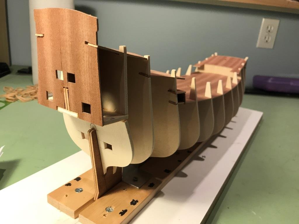
All decks installed along with the stern upper transom. I found and downloaded a .pdf copy of Herman Ketting's book 'Prins Willem' which appears to contain quite a bit of useful information on the construction of the ship. My only problem is that it's written in Dutch! There are some nice pictures though that might come in handy.


-
Hello Koen, thanks for following along
-
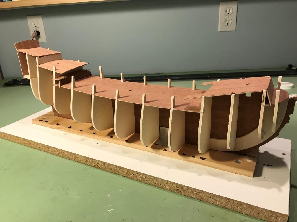
Continuing with the deck installation, the forecastle and quarter deck were glued in place.
-
EJ, thanks for looking in. As I mentioned to Elijah, so far the kit supplied material is fine the only draw back is the manual but the drawings are good.
-
Antony, welcome and thank you. Hi Duff, thanks for looking in.
-
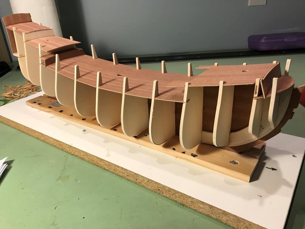
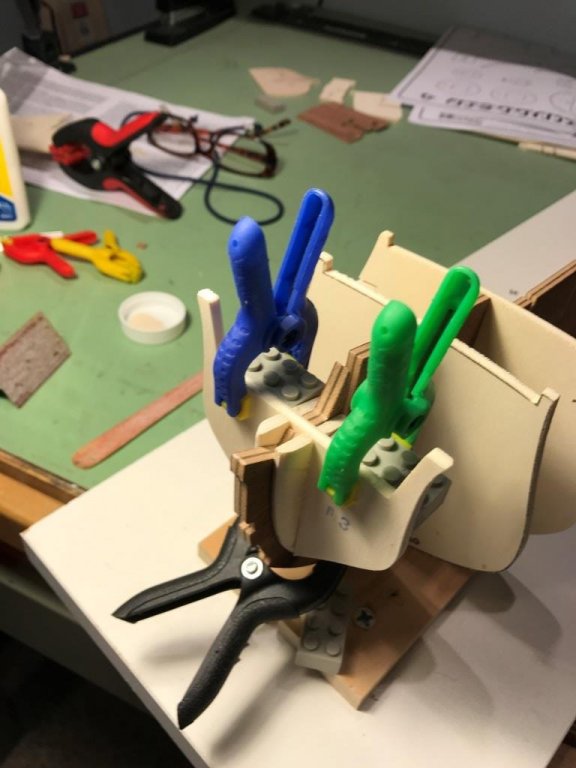
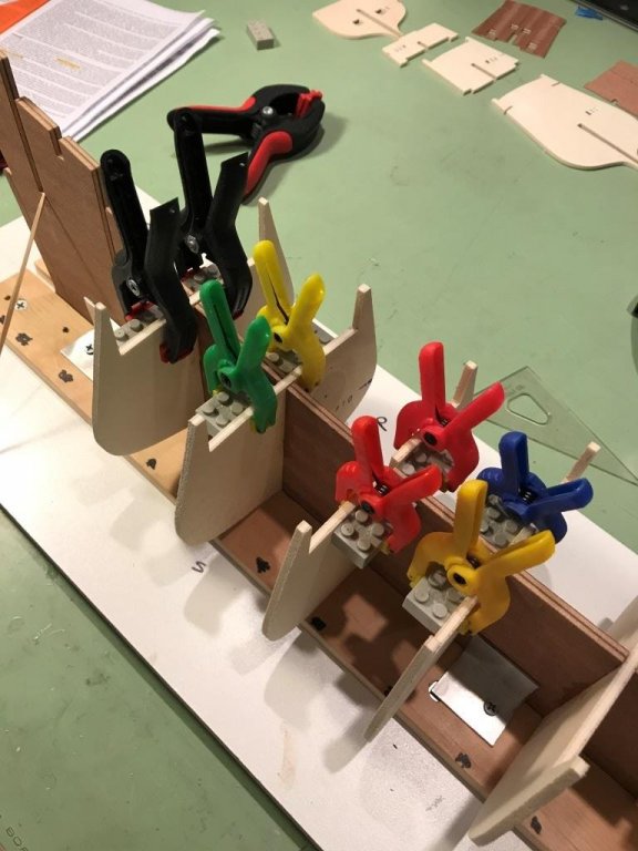
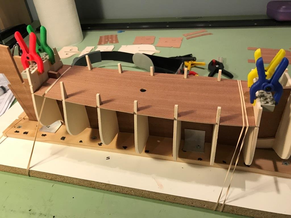
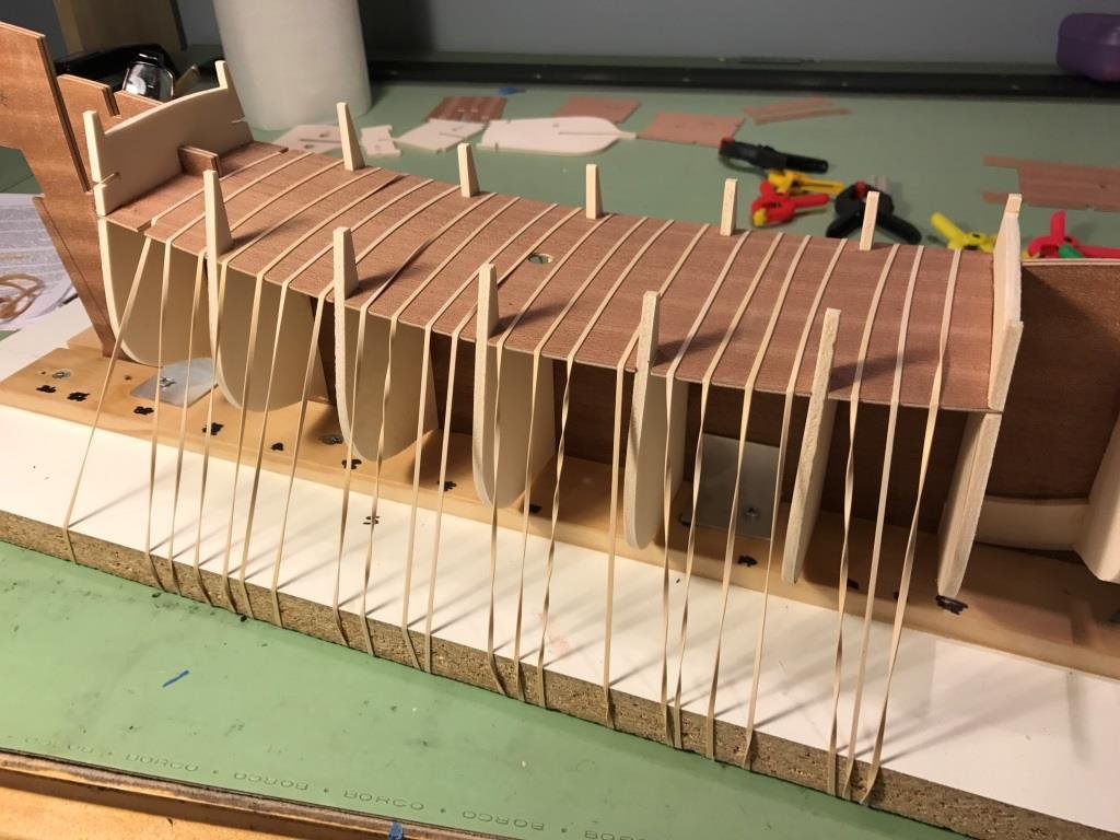
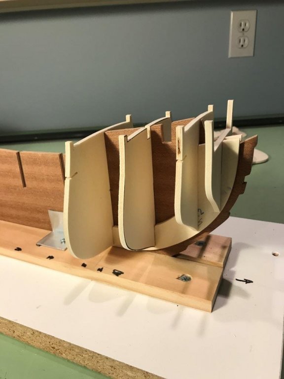
Starting to reassemble the bulkheads for their final placement on the BF using clamps and my trusty Legos. More clamps and legos Setting the main deck. Reminds me of something out of Gulliver's Travels. The rubber bands worked out nicely because they pulled the deck down along the curvature on the bulkheads.
-
Thanks Elijah, From what I've looked at so far the parts appear to be of good quality, I haven't looked at any of the blocks or fittings yet so my opinion may change. Congrats to your daughter too, and thanks for the steamboat info.
-
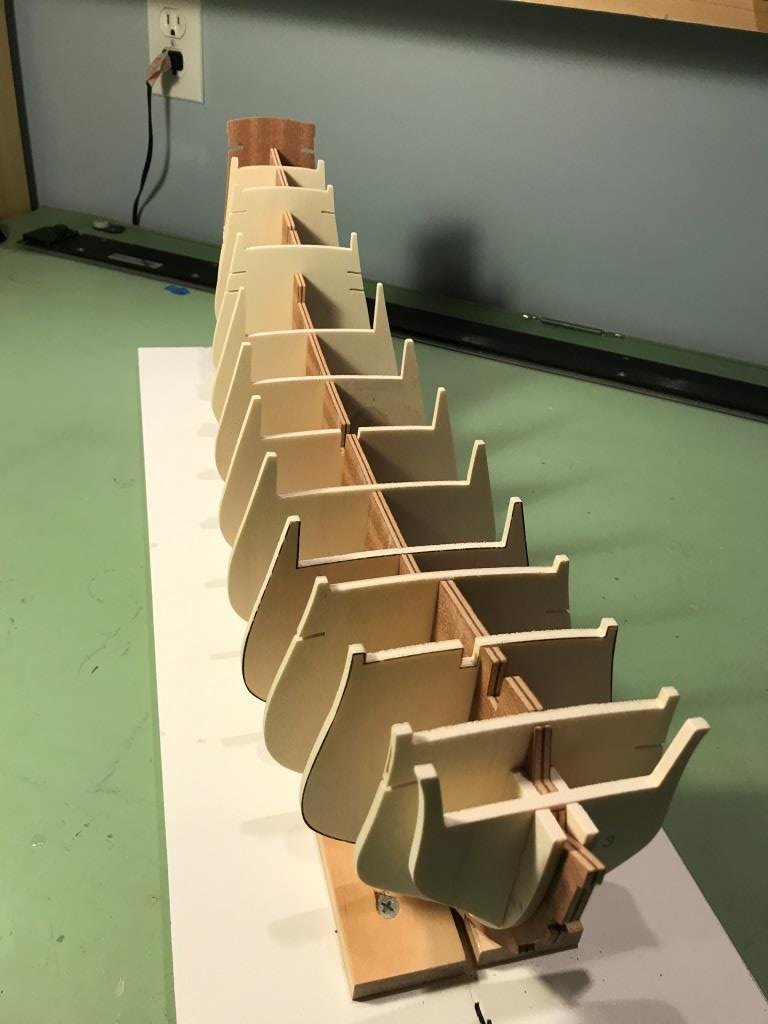
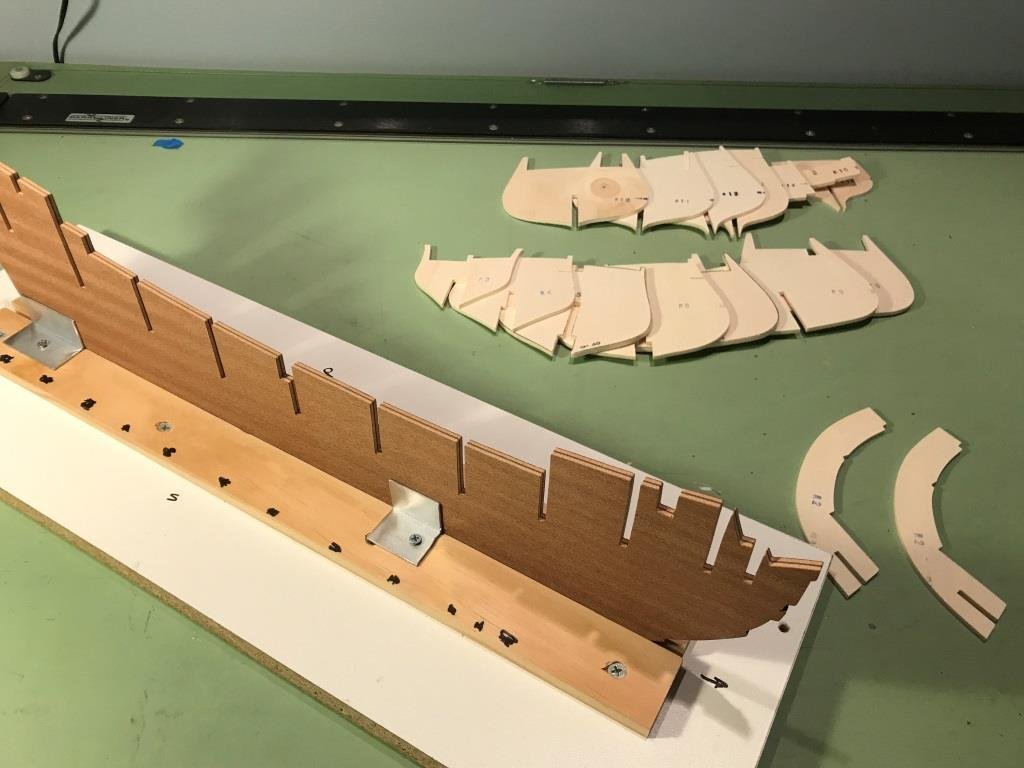
I had mentioned before how lacking the instruction manual is but I had to laugh because although this is an advance kit the manual states and I quote, ‘… model may be constructed with a few standard tools, a hammer, a few small files, pliers, a pair of scissors, a knife cutter, sand paper and some glue…’ Hope the wife doesn’t see this or there go all the tools I was going to buy. Unlike the Syren model bulkheads which came laser cut but still on large sheets this kit’s bulkheads are all cut out for you. The bulkhead former (BF) was also pre-cut and had no warpage at all. The directions recommended to dry assemble all the bulkheads and decks prior to gluing anything in place. I’m glad I did this because there are some bulkheads that can’t be installed without installing the decks along with them. The decks are loosely installed so they appear a little crooked. All the slots in the bulkheads needed some sanding for them to fit properly on the BF. I decided to do some preliminary shaping of the two bow fillers before permanently attaching them to the BF. This is done so the hull planking runs smoothly to the bow. The last task to be done prior to reassembling everything and gluing in place is to cut the gun ports from the stern bulkheads. Making a copy of the bulkheads from the drawings, I cut them out to use as patterns to locate the gun ports. The ports were cut using an x-acto knife with a #11 blade and then filing the edges.


-
Thanks Jack, it’s been a while since we last spoke. I had a lot of things going on since then with retiring from work after 40 years, daughter graduating college, then I wasn’t feeling well for a while but I think I’m back in the groove again. This build should keep me busy.
-
Hi Elijah, Thanks for looking in. I've been looking in on your builds and you're doing very well.
-
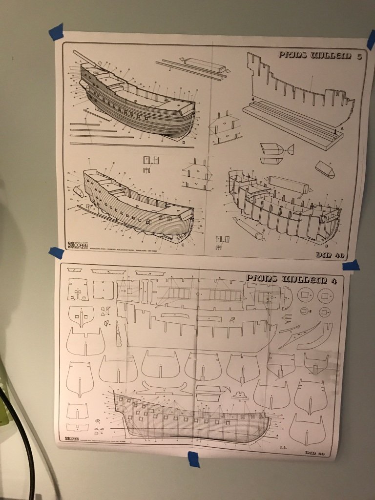
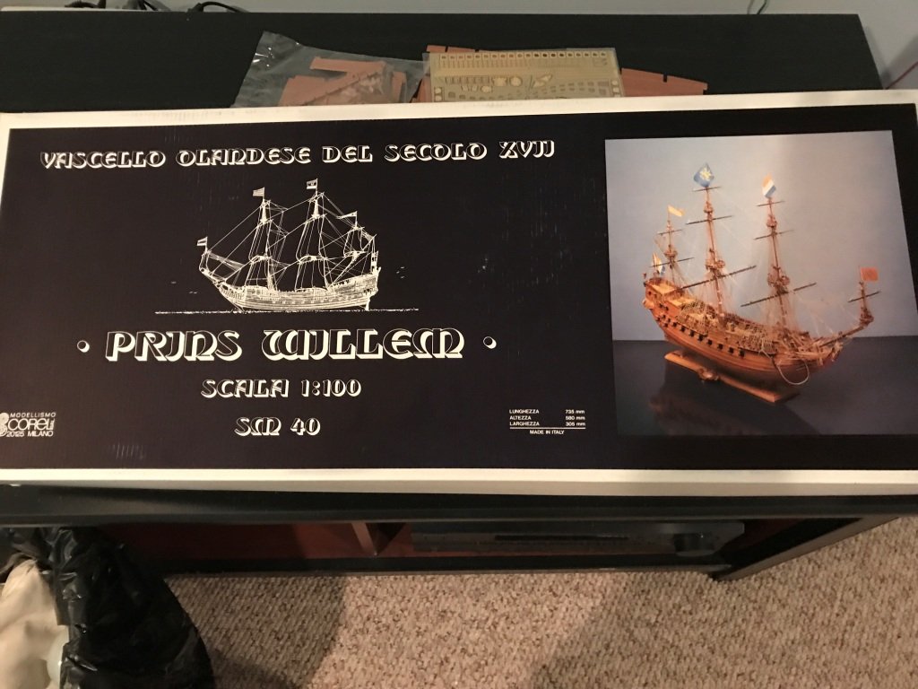
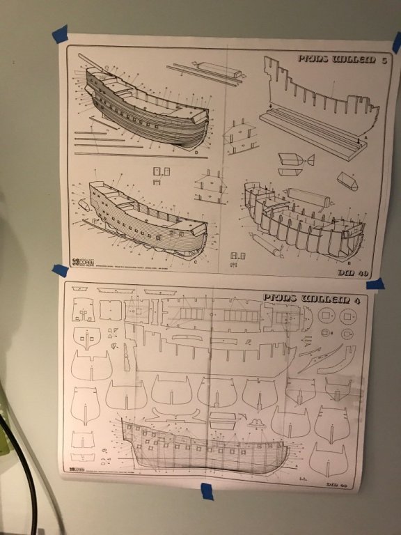
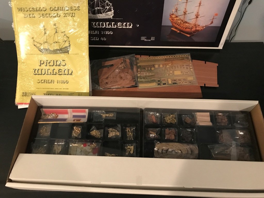
Hello all. I had debated back and forth as to whether or not I would do another build log and I guess you can tell what I decided. This will be my third kit built ship and decided on the Prins Willem by Corel. Prior to this I had attempted a scratch build of a sidewheeler steamboat but came to the realization that I’m not quite ready for that leap. A little background information on the ship for those interested. Owner: Dutch East India Company Built: 1649-1650 Maiden voyage: May 5, 1651 Sank near Madagascar 1662 due to violent weather Crew of 276 Displaced: 700 tons Length: ~137 ft Armament: 32 guns A replica was built in 1985, but was destroyed by fire in 2009. The kit was purchased through Model Expo and although it was back ordered it only could two weeks to receive. The model scale is 1:100, with a finished length of 29-1/2” and a height of 23". The kit is POB with laser cut wooden frames and the hull is double planked. There are quite a few parts to this kit and even though I know I should do an inventory of them I am forgoing that task and will check for the required pieces as I proceed. Fingers crossed. Obligatory exterior and interior box pictures. There are ten sheets of drawings which appear to be quite good, the instruction manual however is a little lacking.


-
Nathan, For the style of text it will depend on what font's are available with the cad software you are using. I use Autocad and use their 'simplex' font for the majority for the dimensions and text. As far as text height I prefer text that is 3/32" high for dimensions and text, for titles I scale the 3/32" text up by 1.5 or 2 times. For drafting the ship I've found using a scanned drawing as an overlay works well. It's also easier to pull dimensions off the scanned drawing than the hard copy. these are just my opinions and seem to work well for most cases.
.jpg.f9ab0f2f26c2f522c7a4030078e0f038.jpg)
.jpg.b8d27e4f1a358732e78799dd2fcd46ca.jpg)
.jpg.9cb7481f8466ff7b7188401881557b65.jpg)
.jpg.850c371bdd8d955bf6da92ada4046c74.jpg)