Clark
-
Posts
310 -
Joined
-
Last visited
Content Type
Profiles
Forums
Gallery
Events
Everything posted by Clark
-
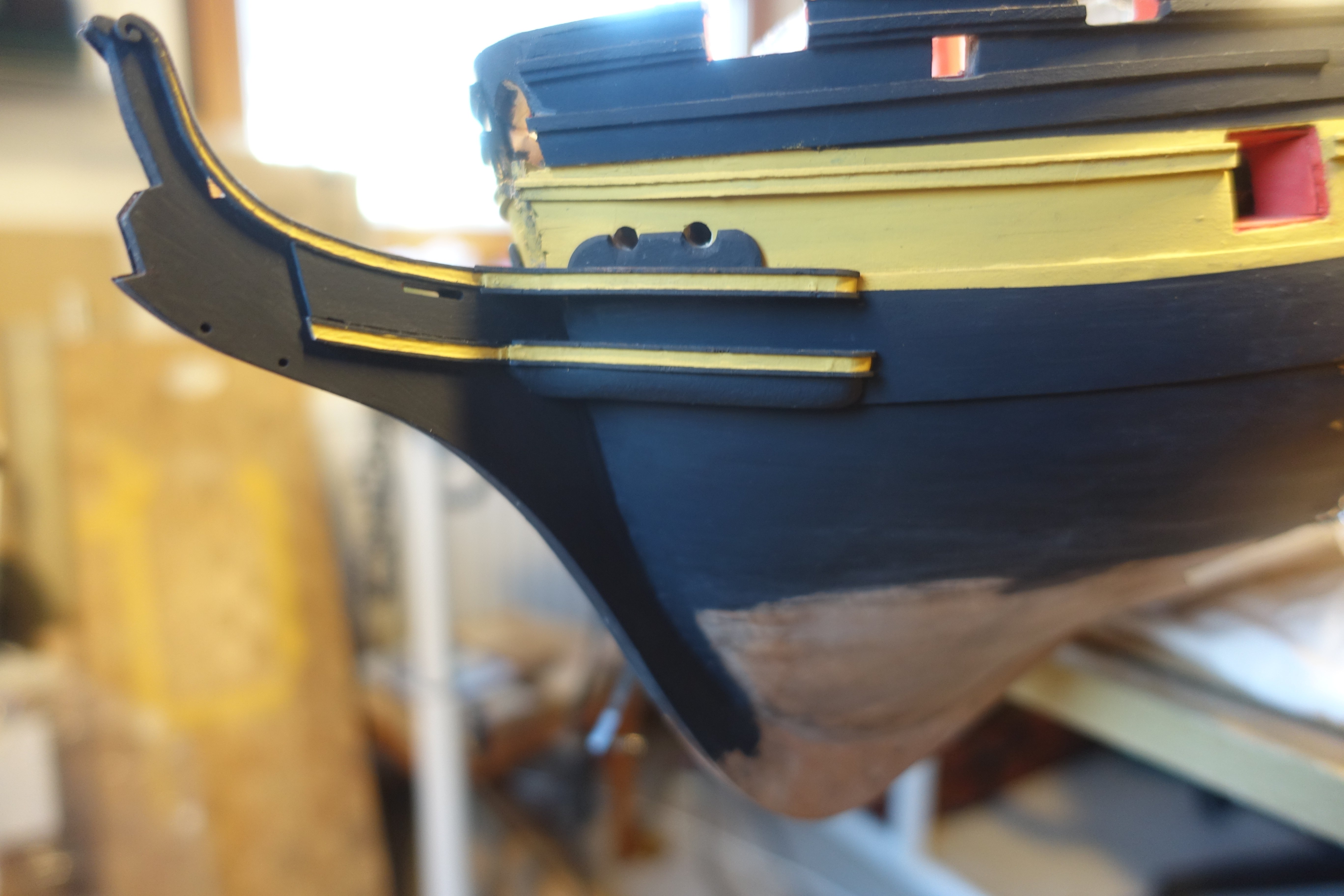
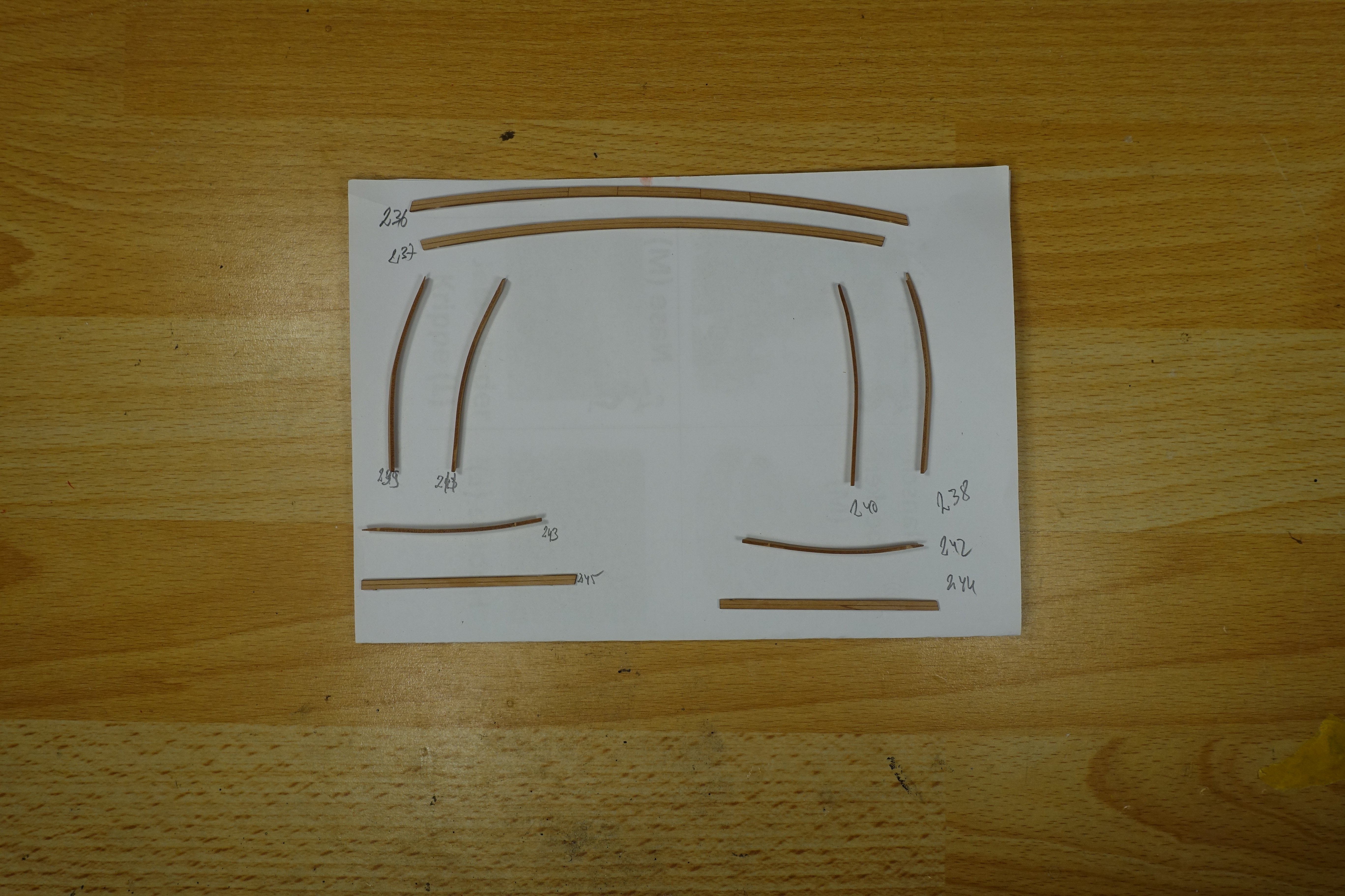
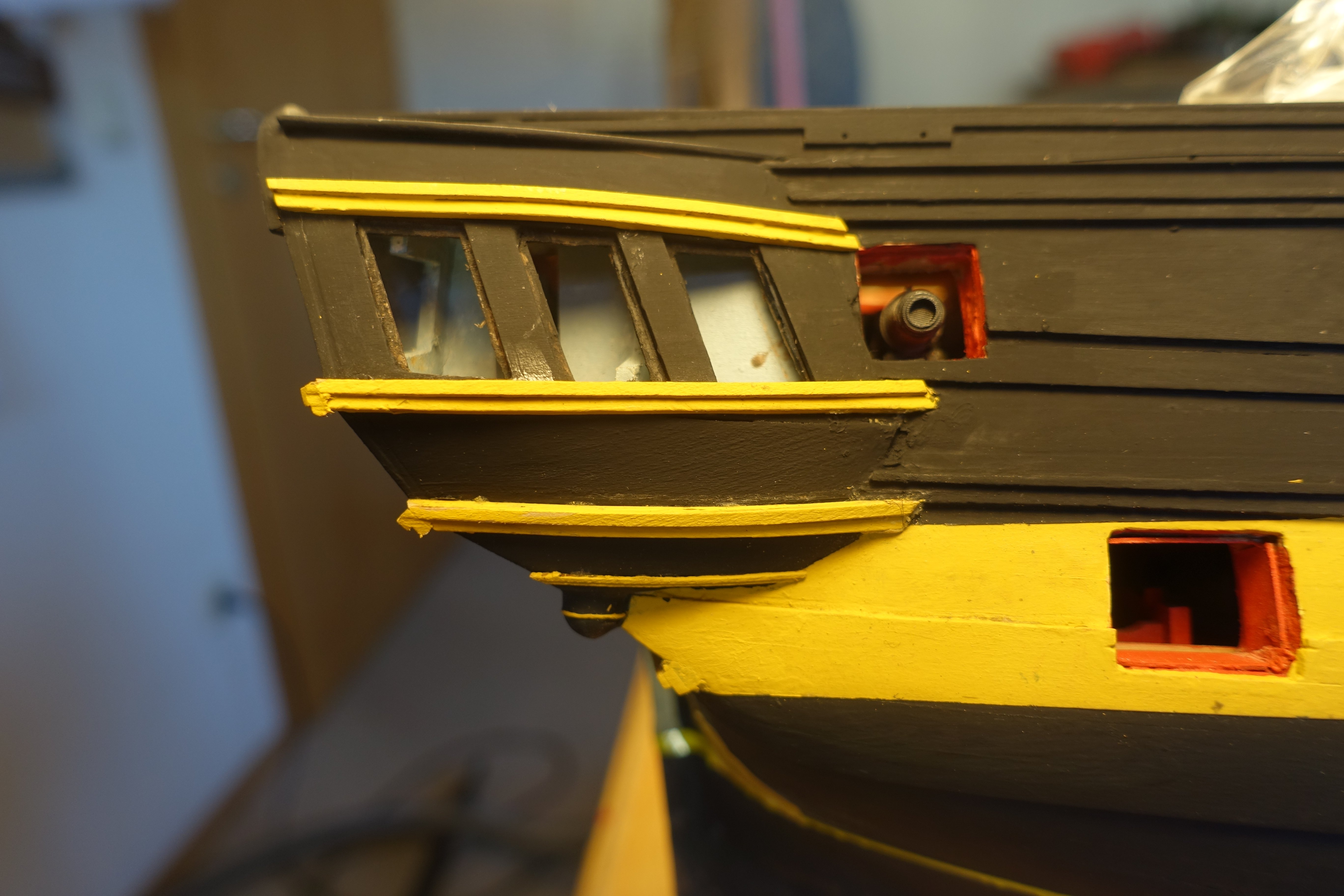
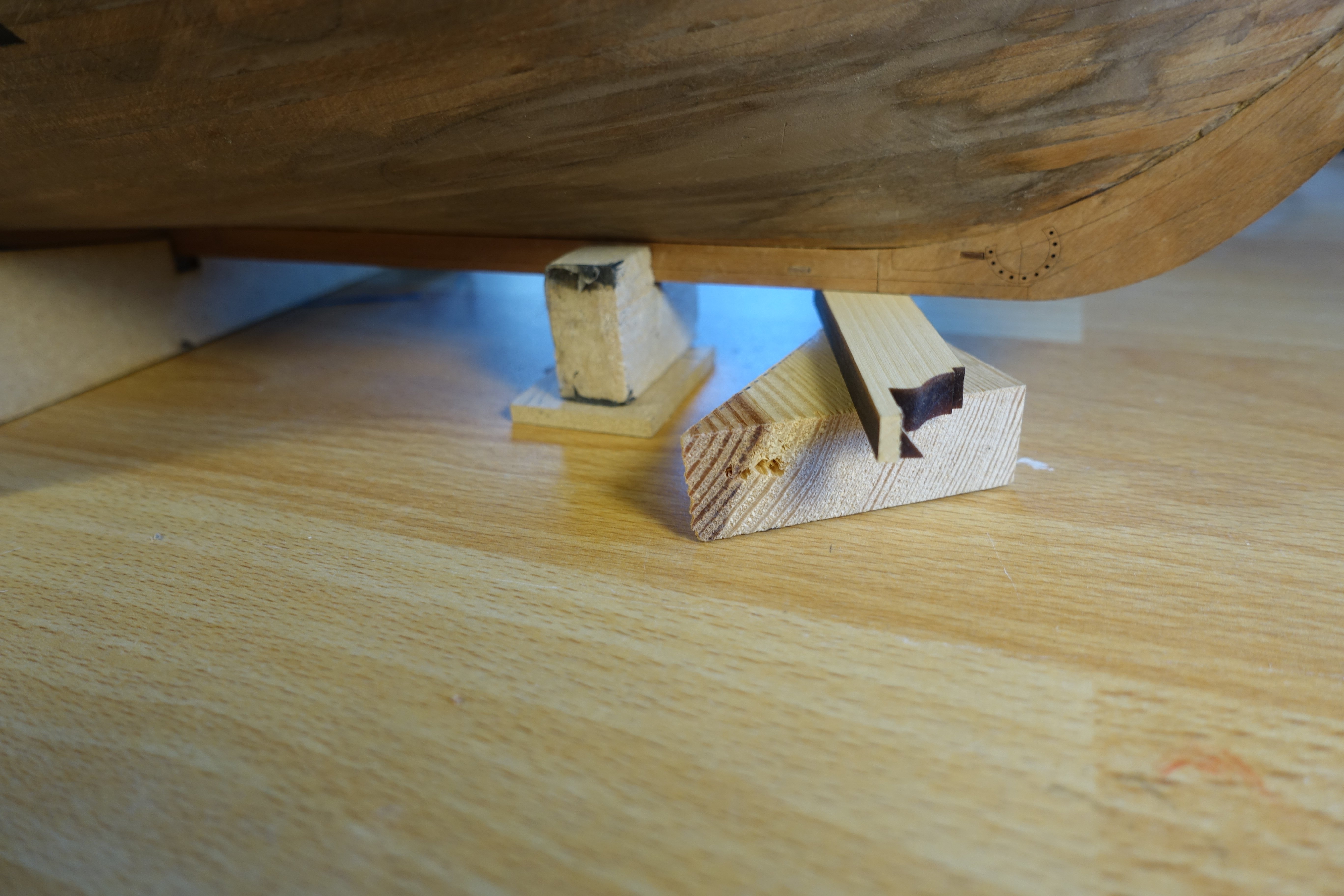
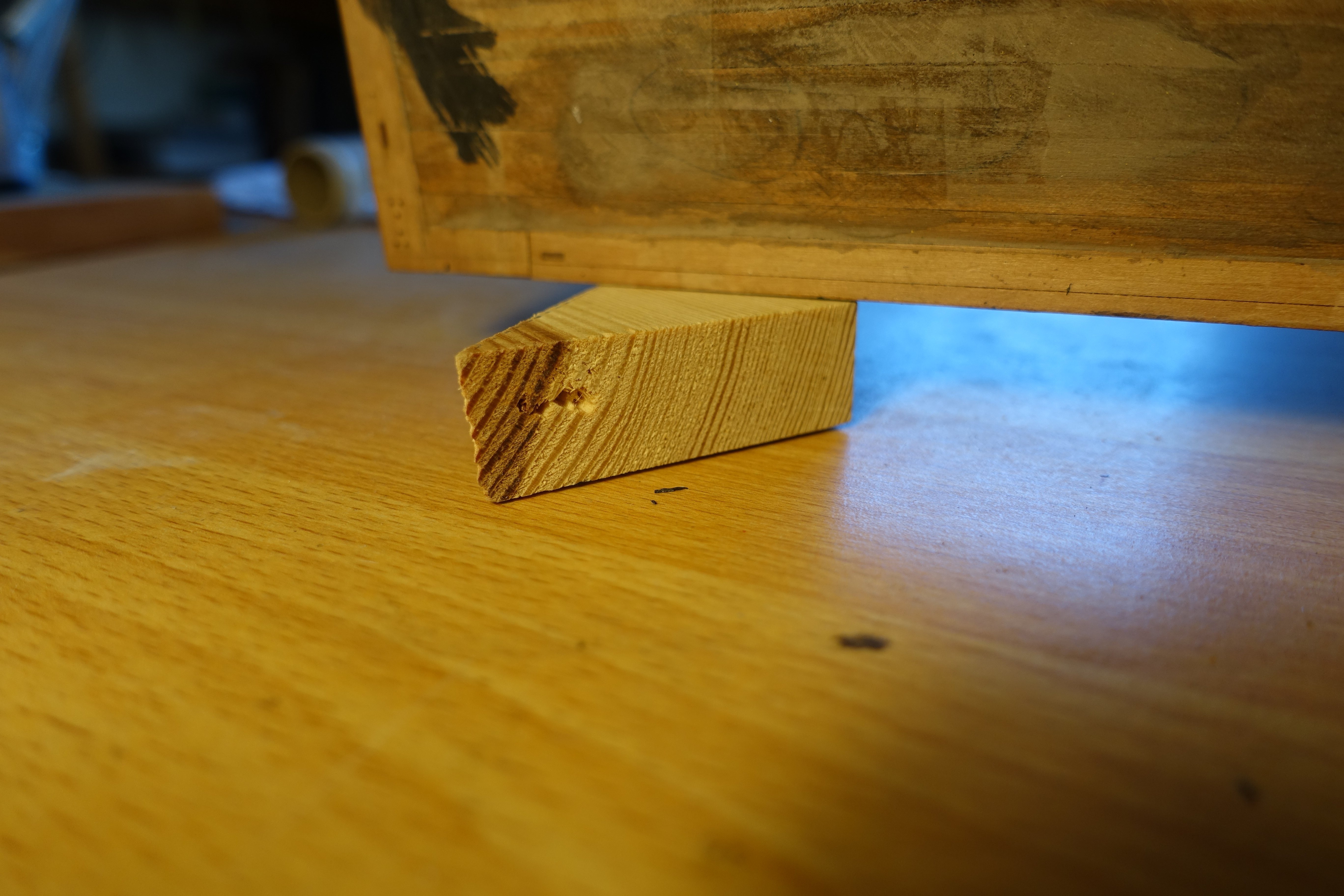
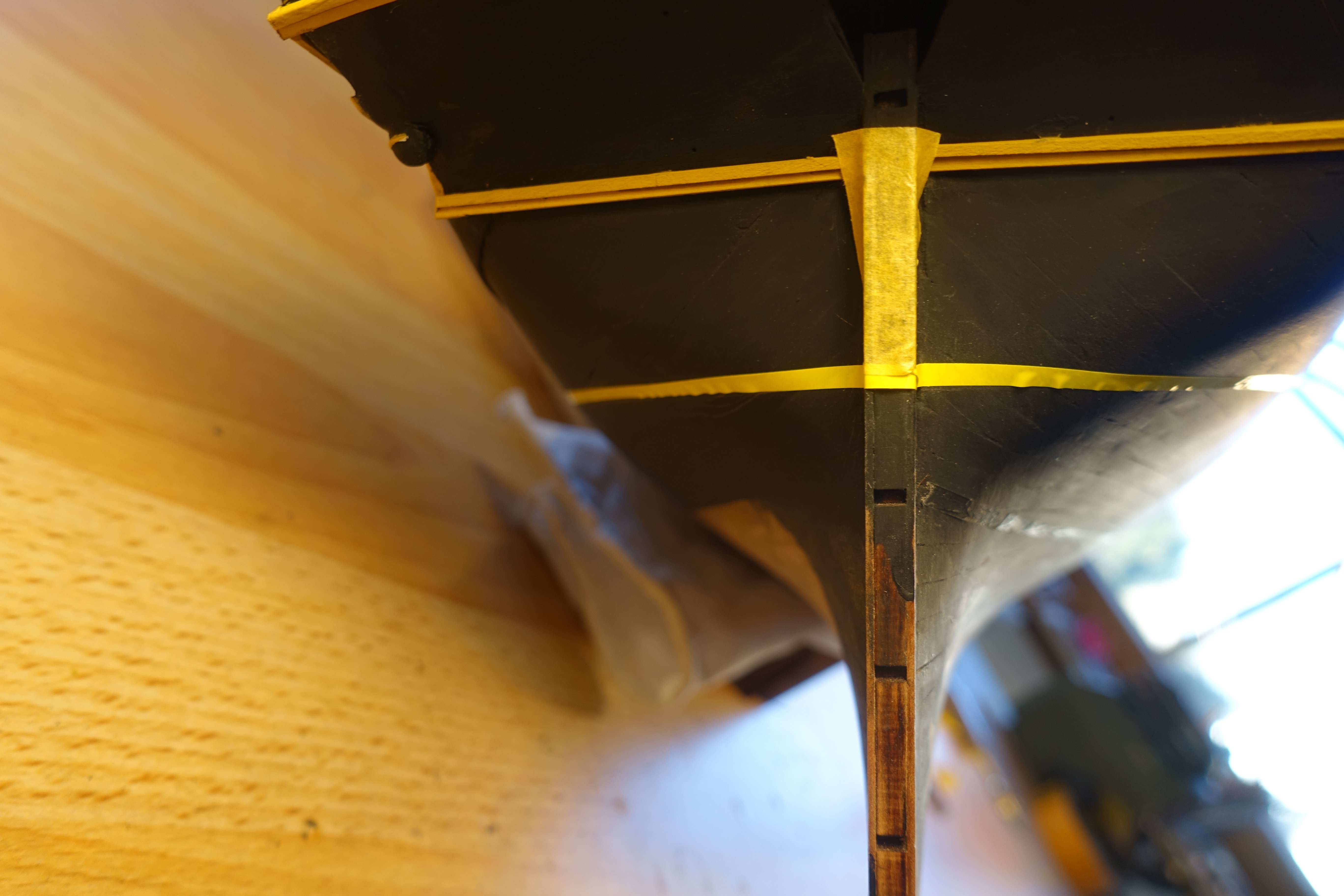
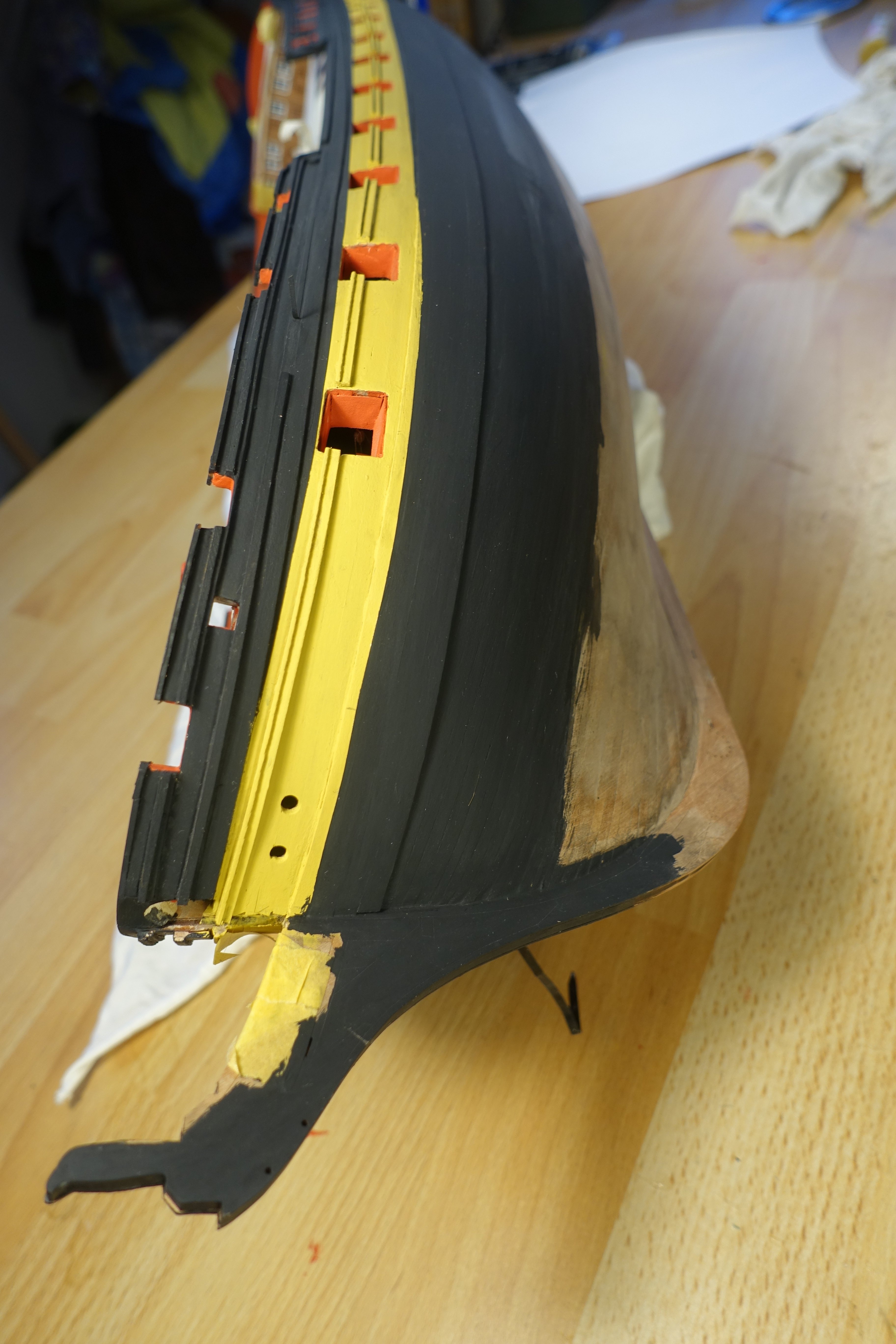
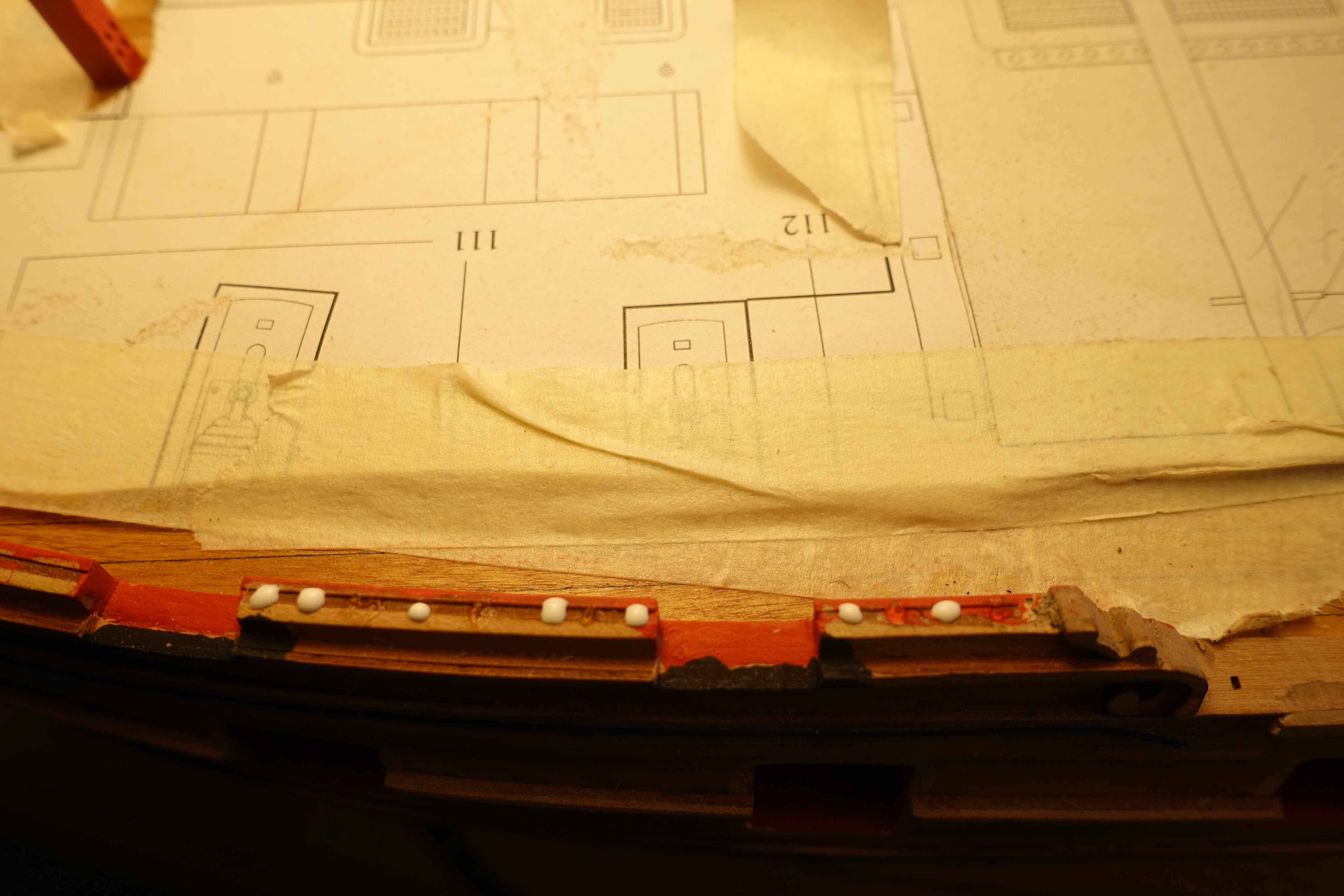
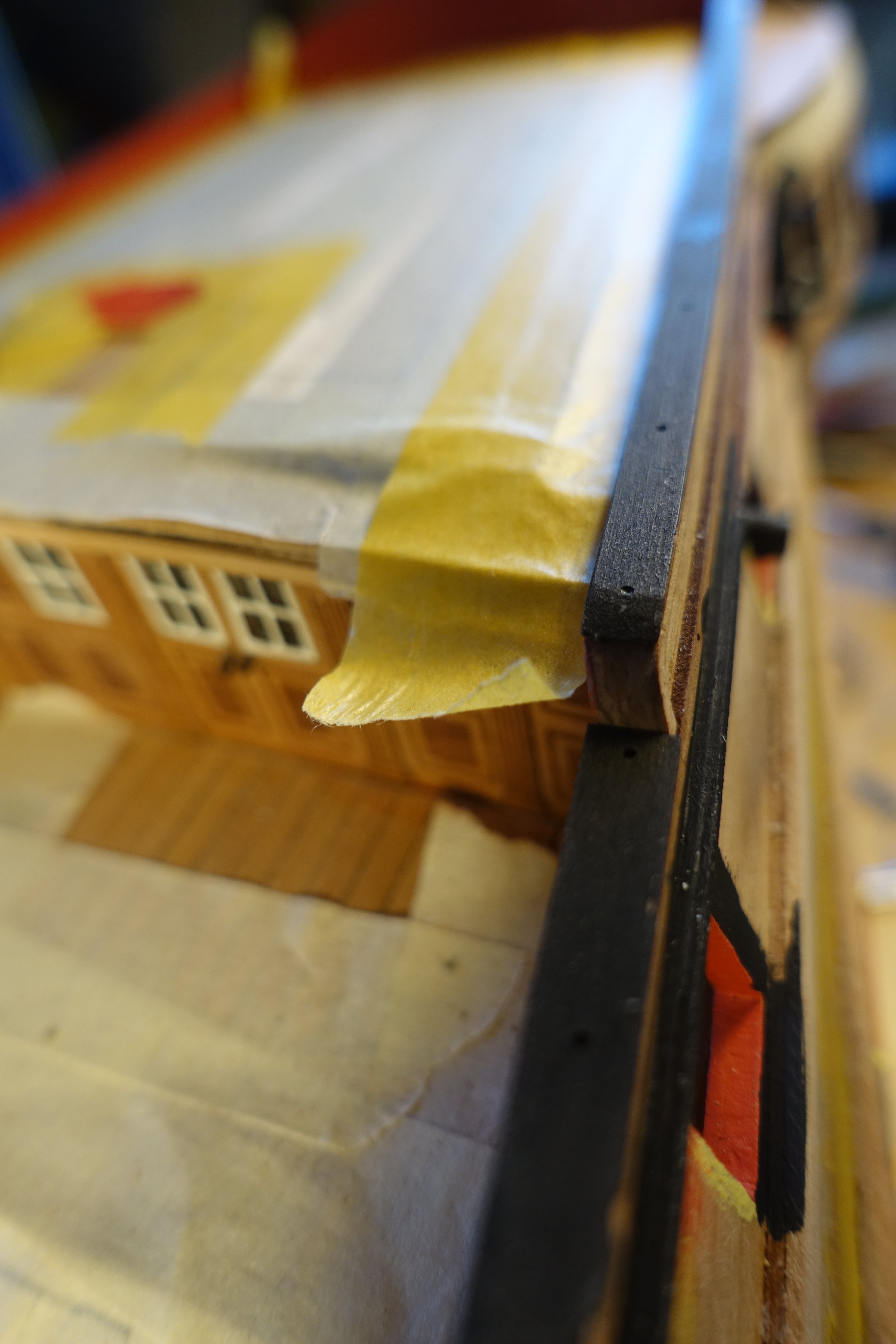
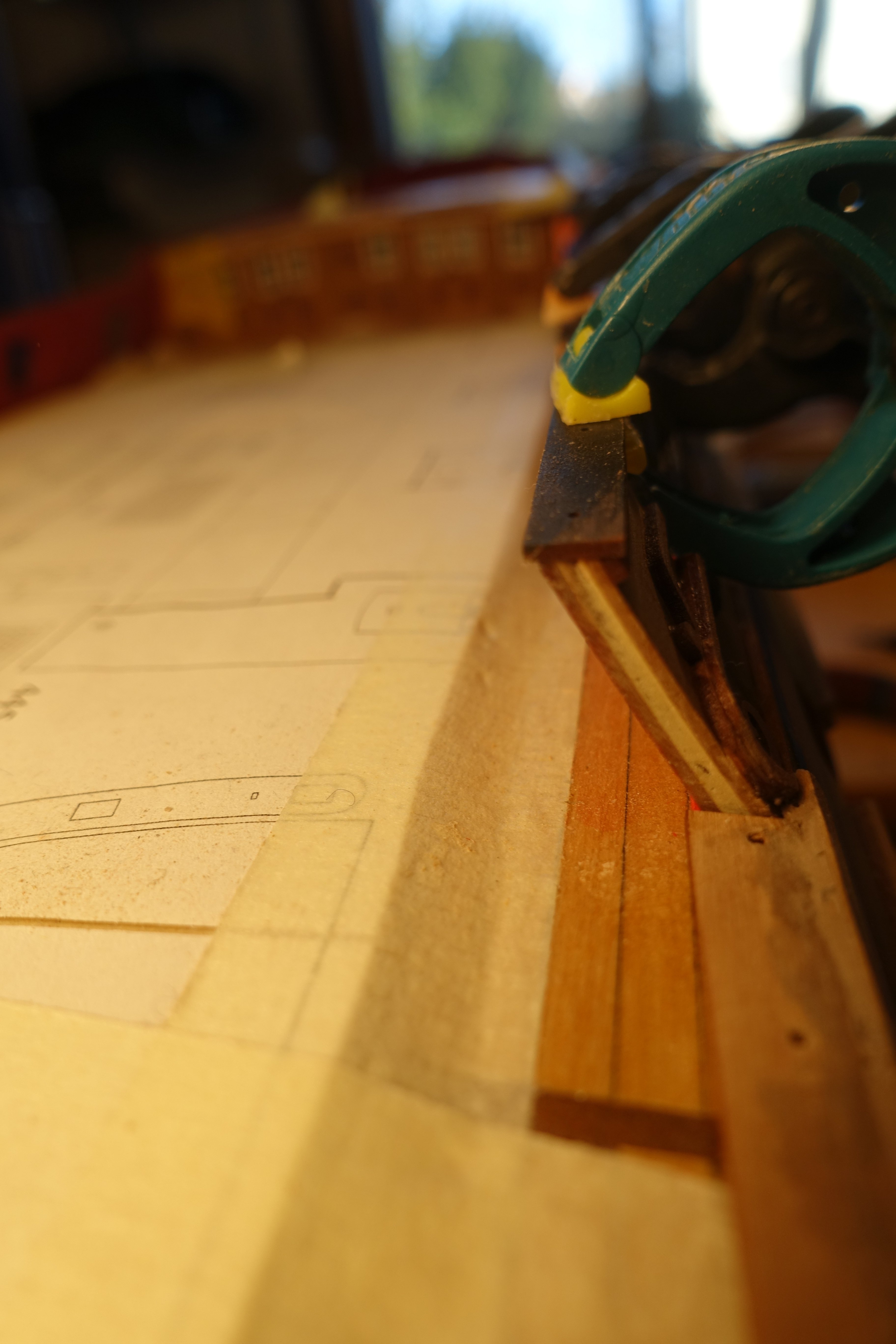
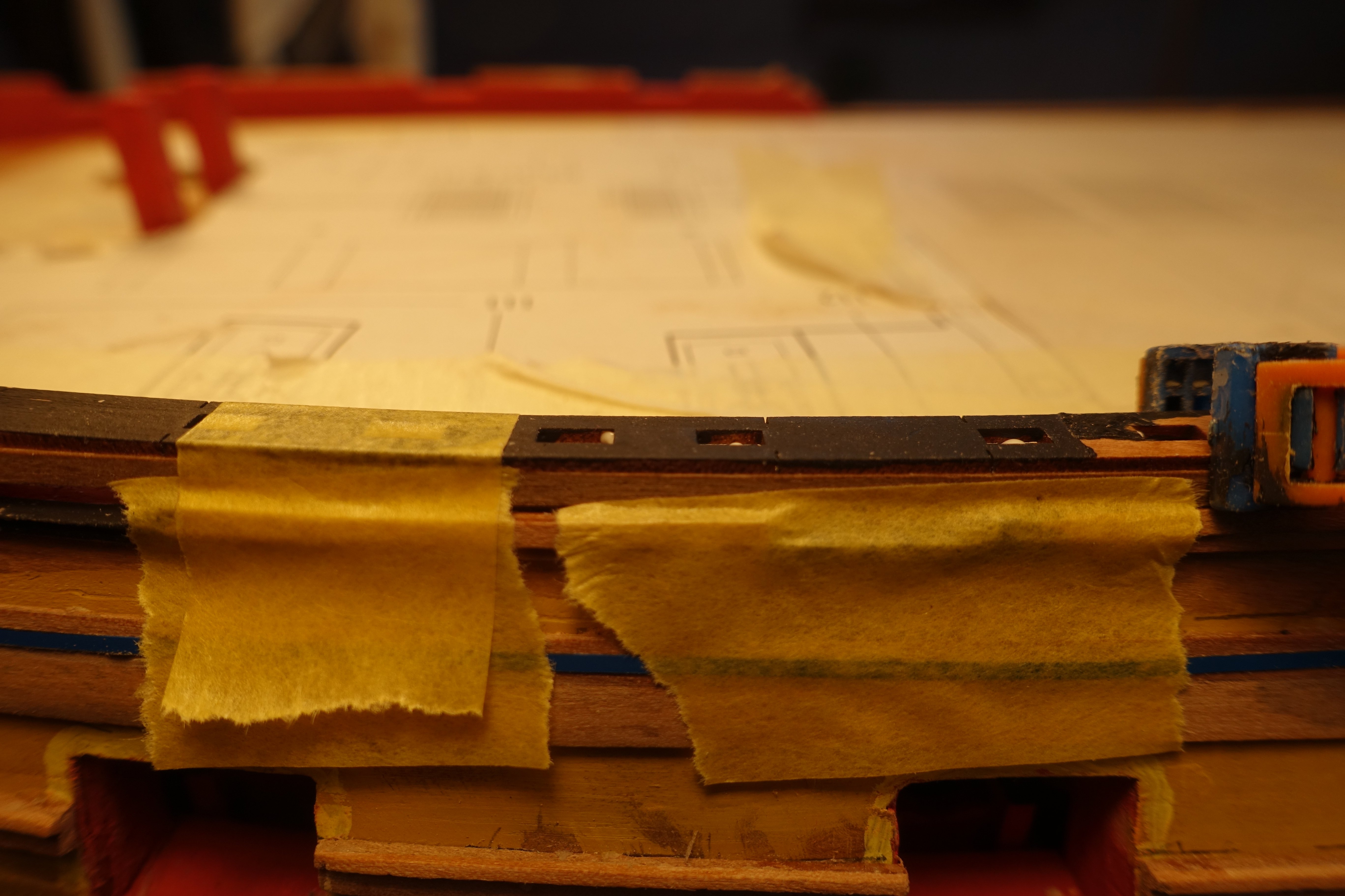
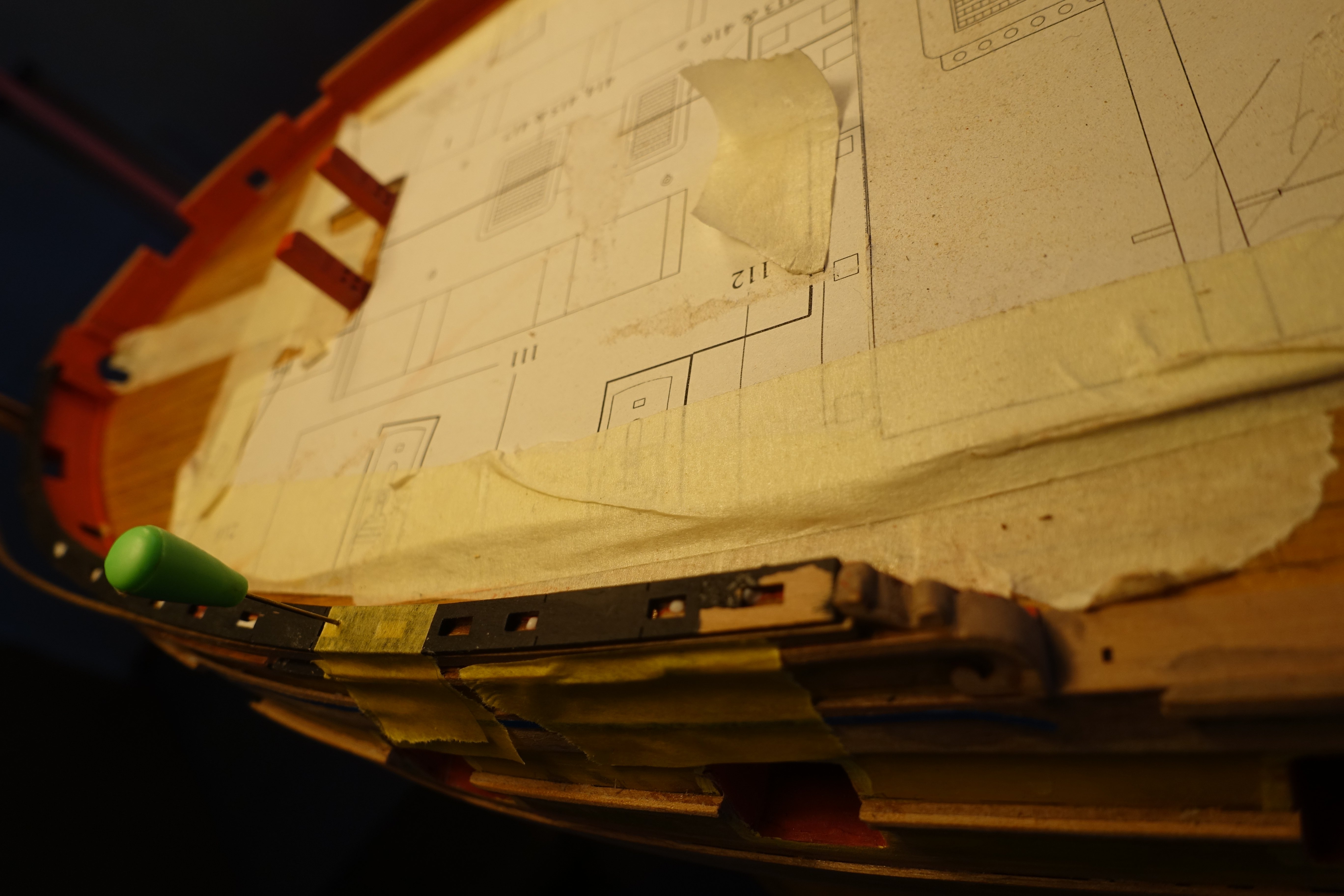
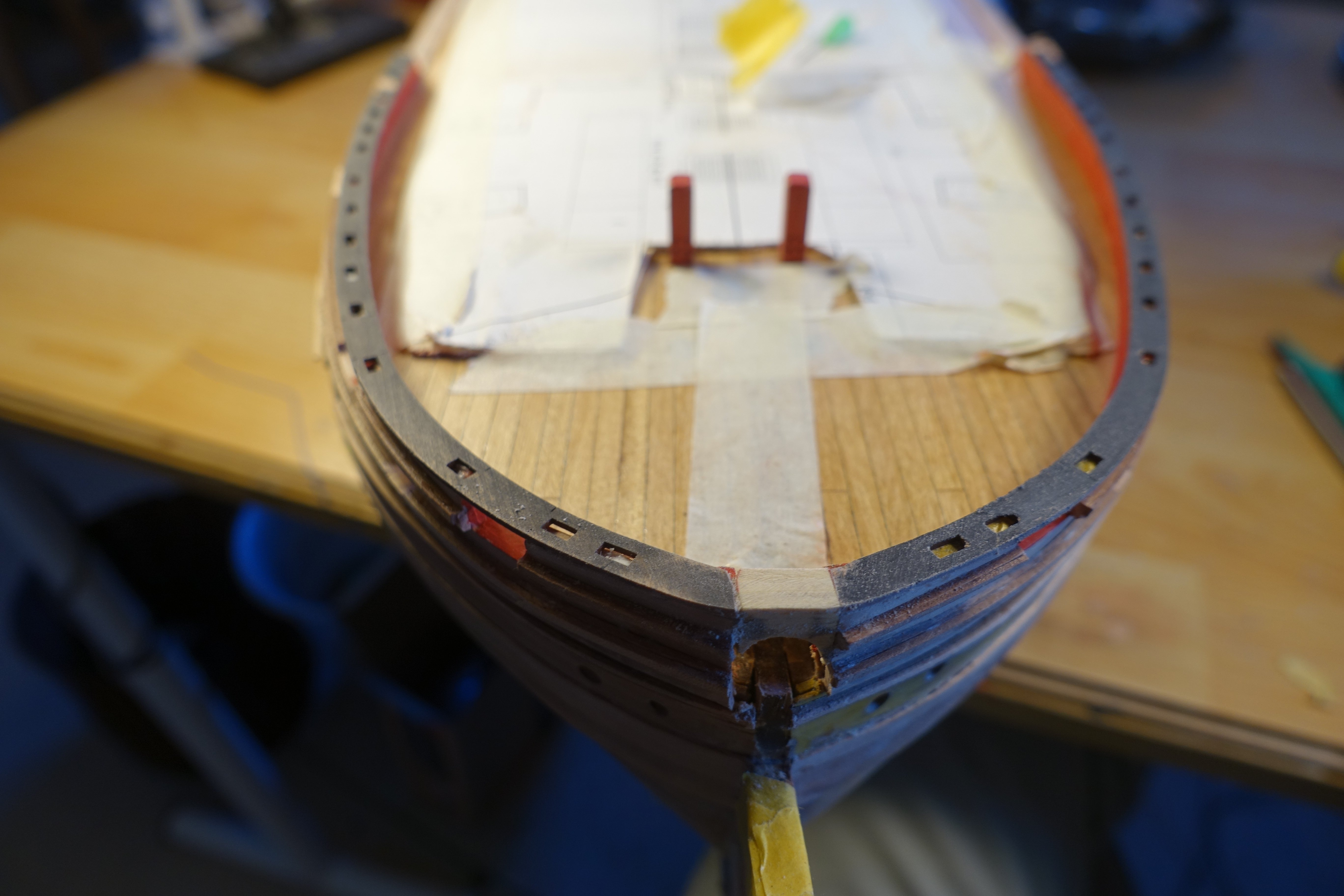
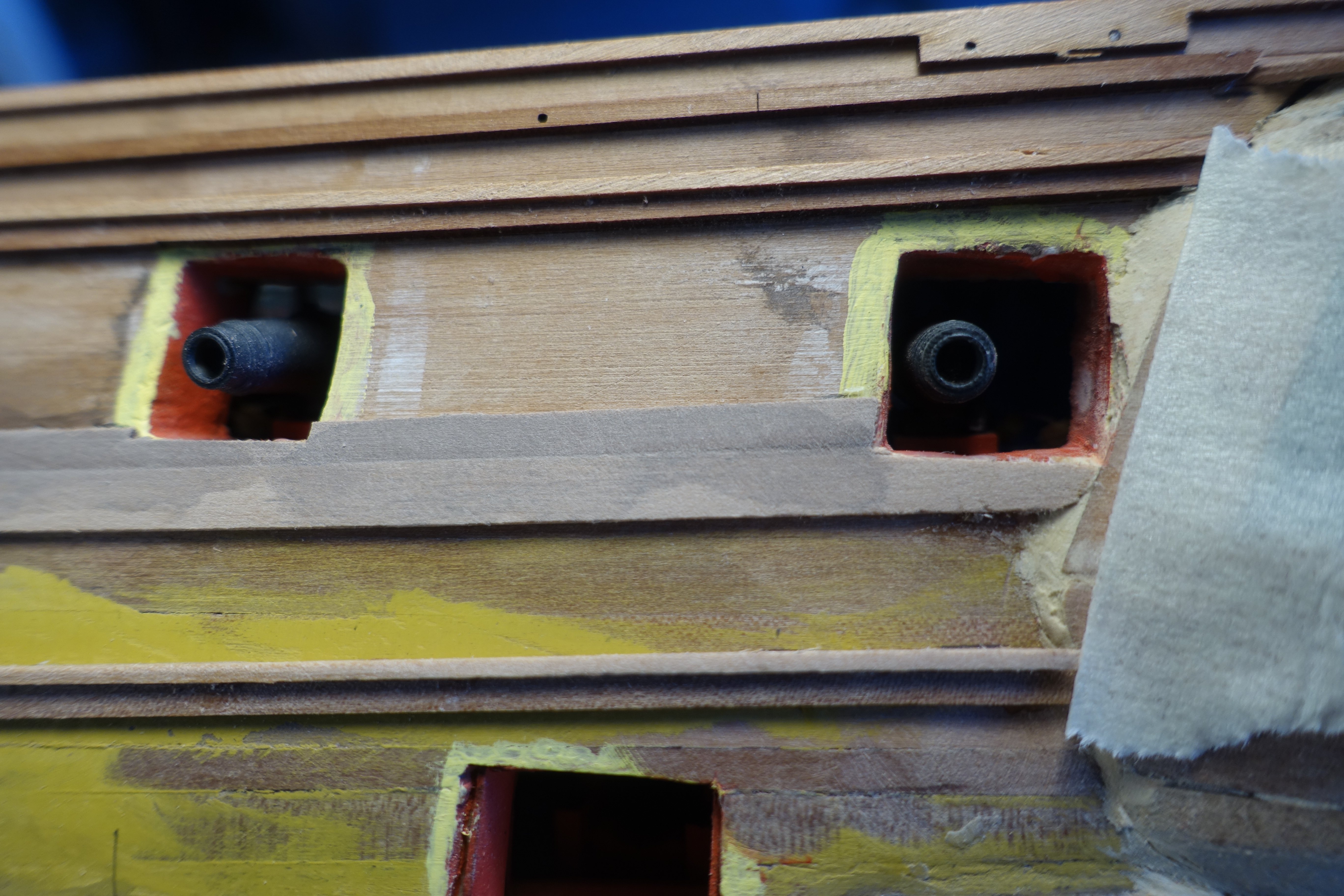
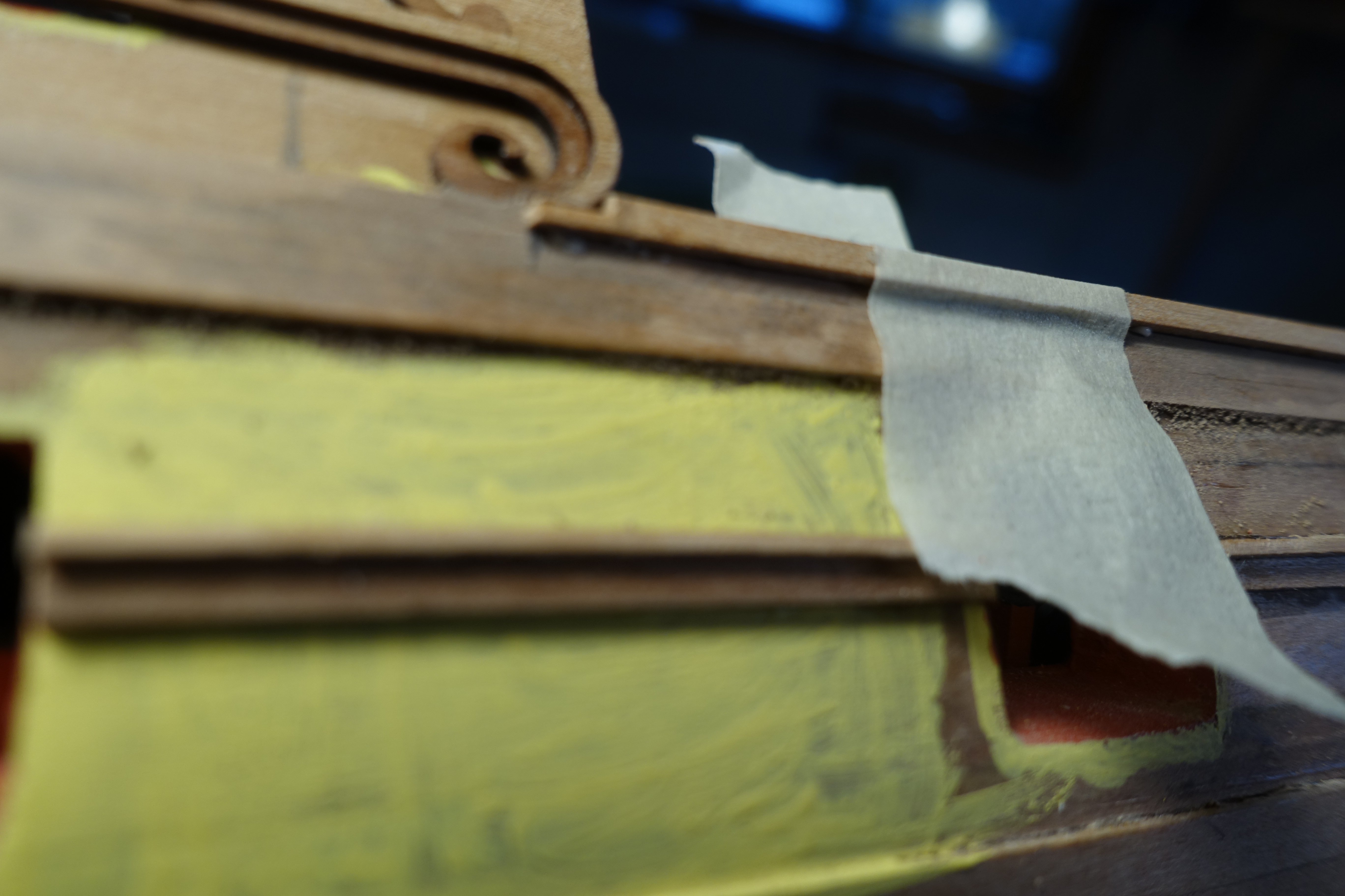
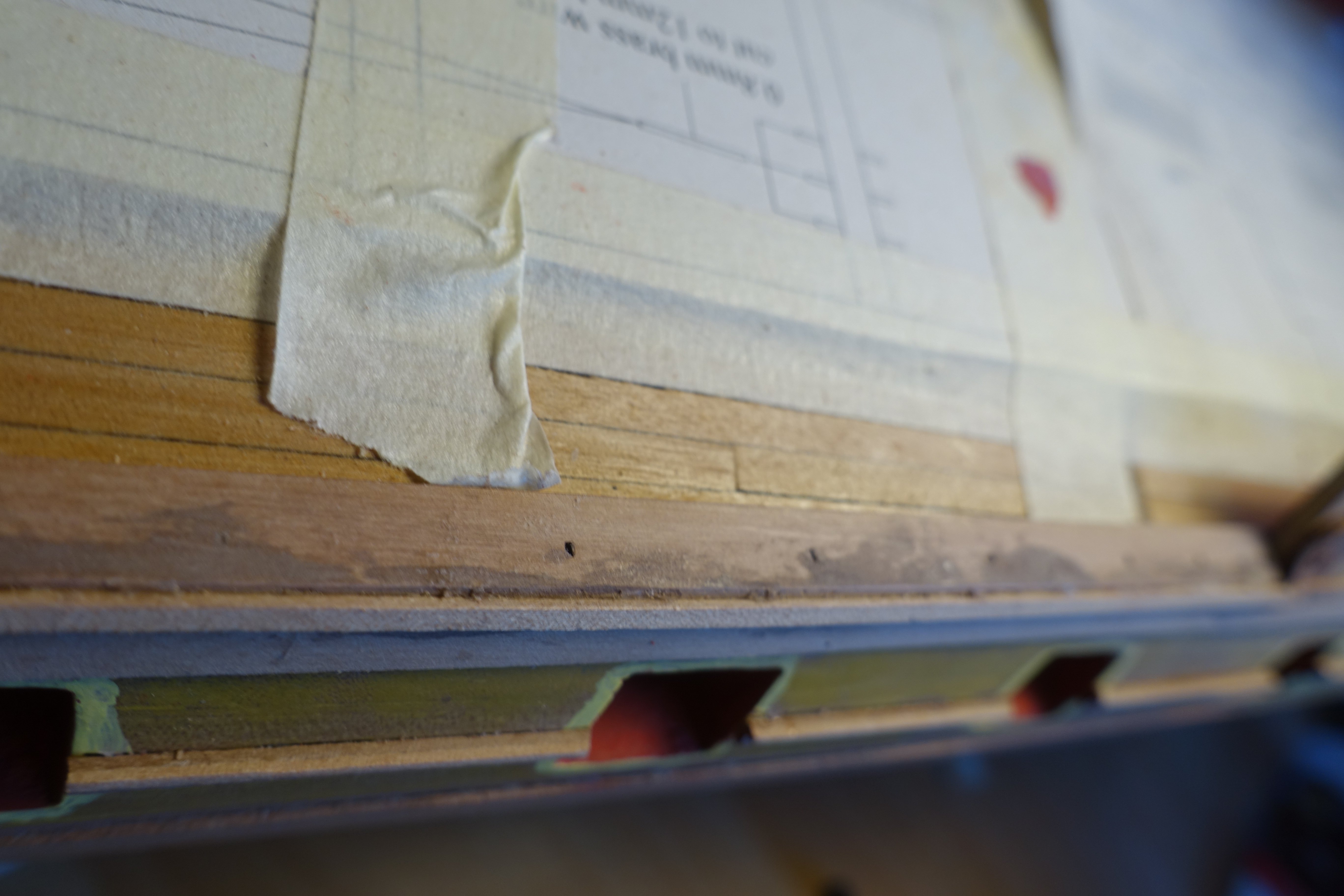
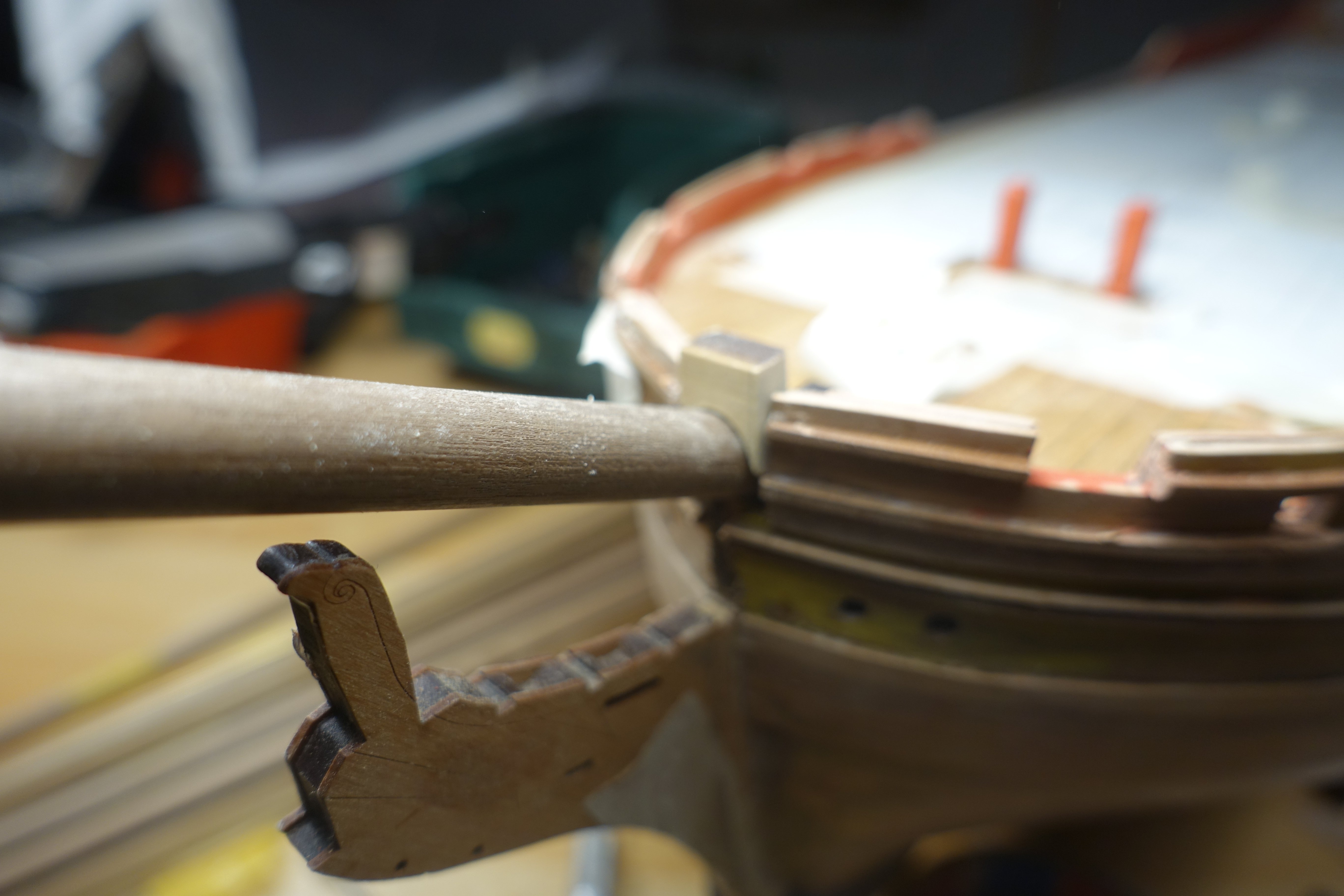
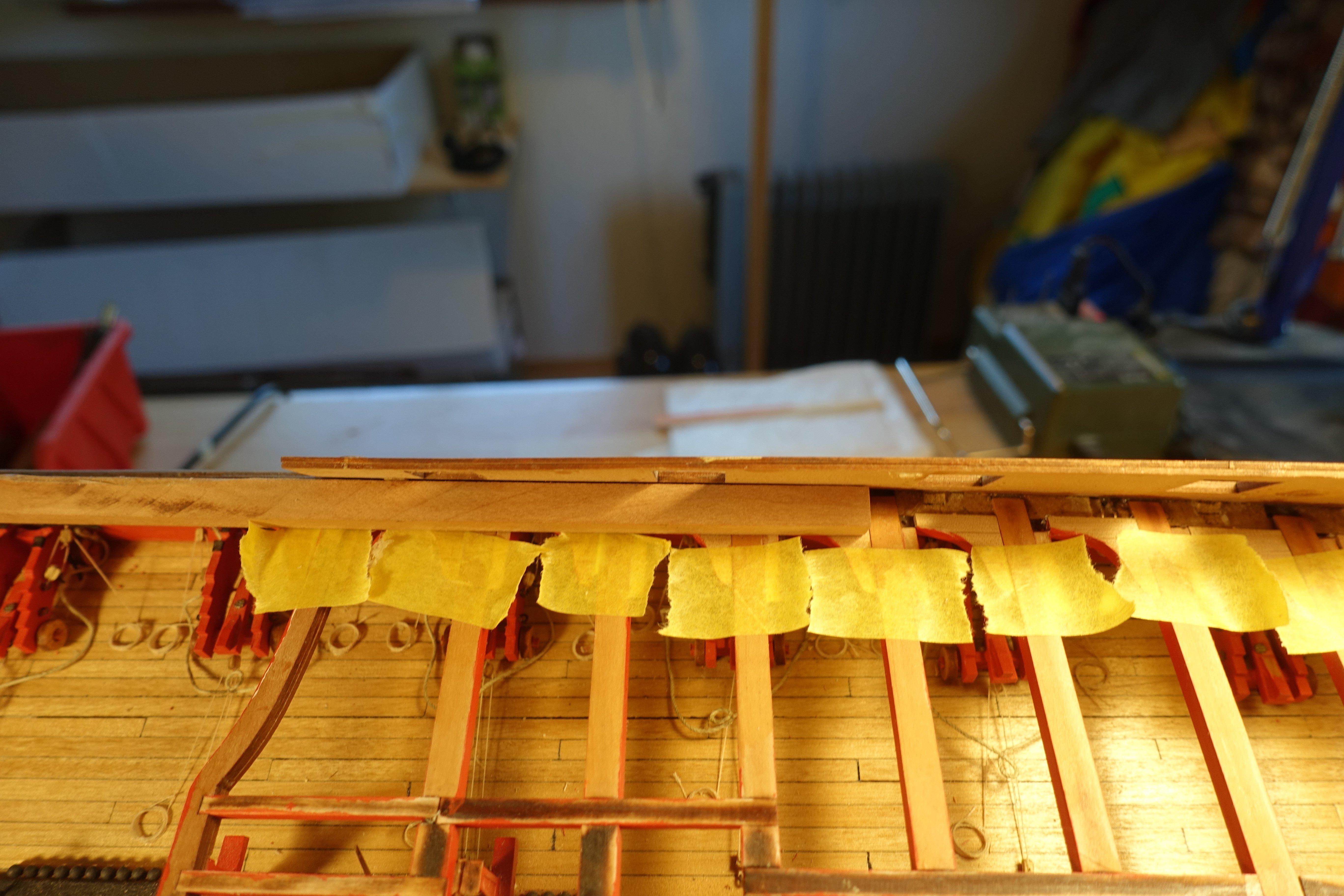
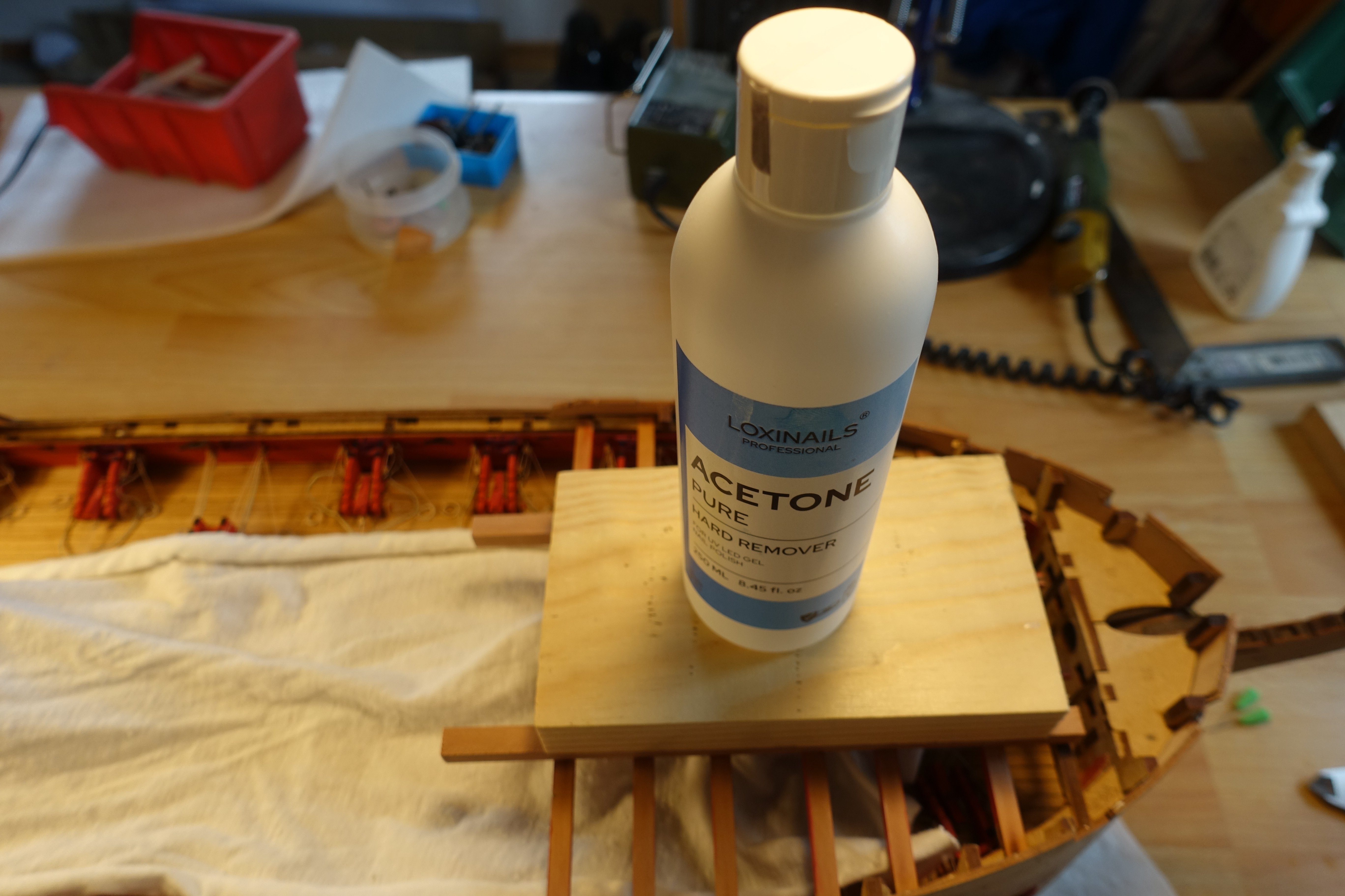
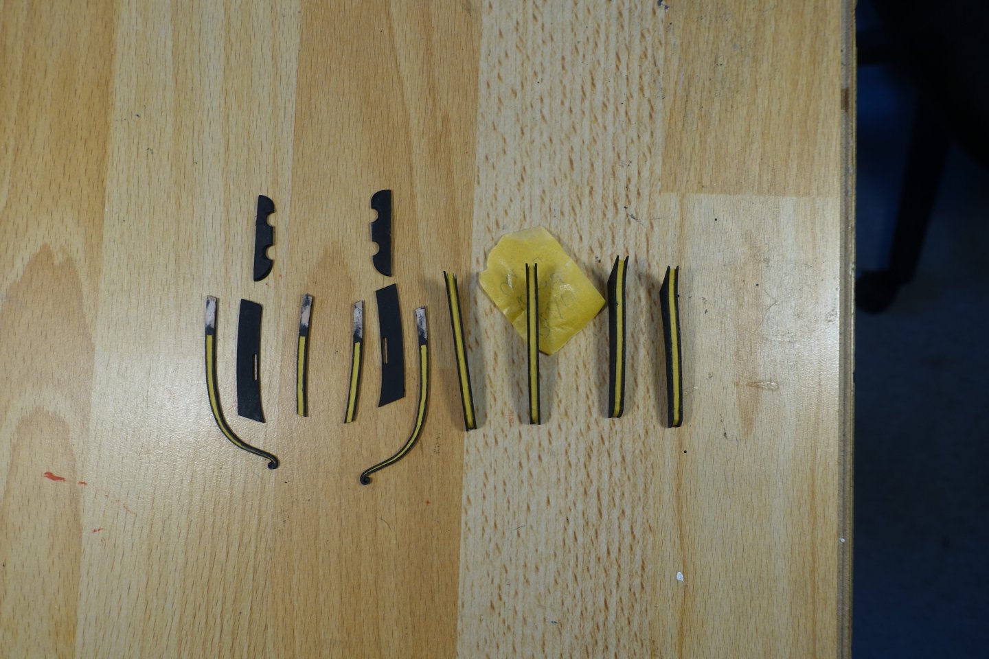
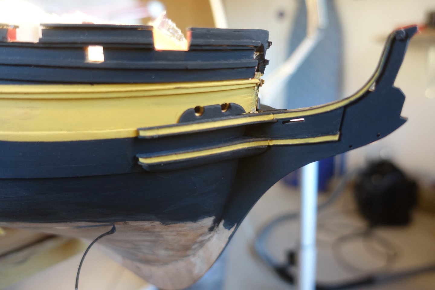
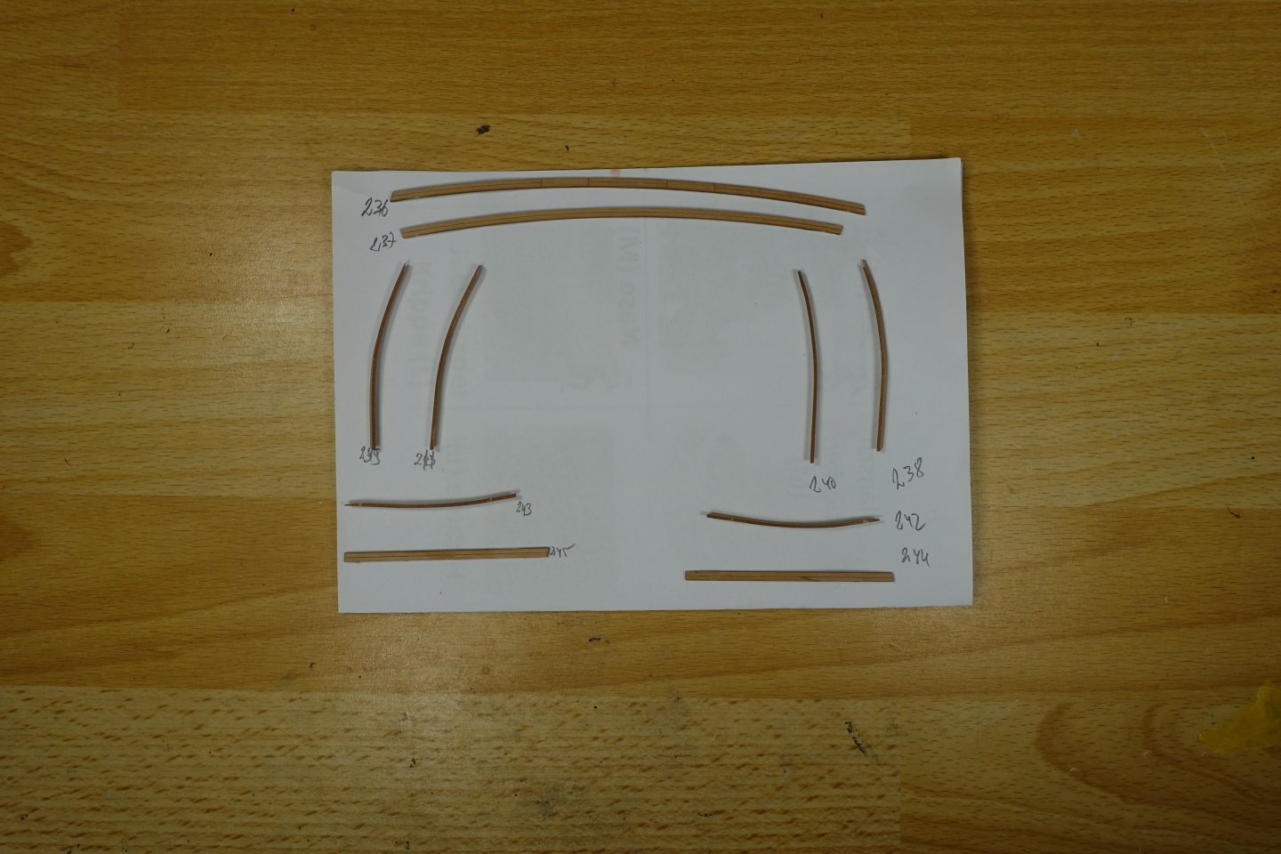
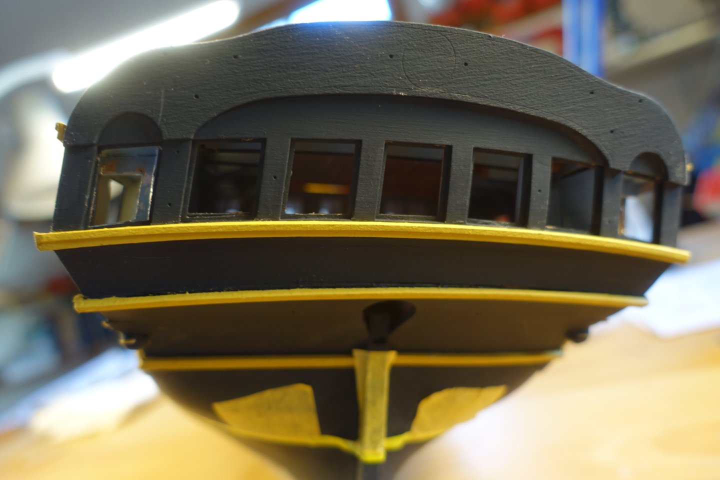
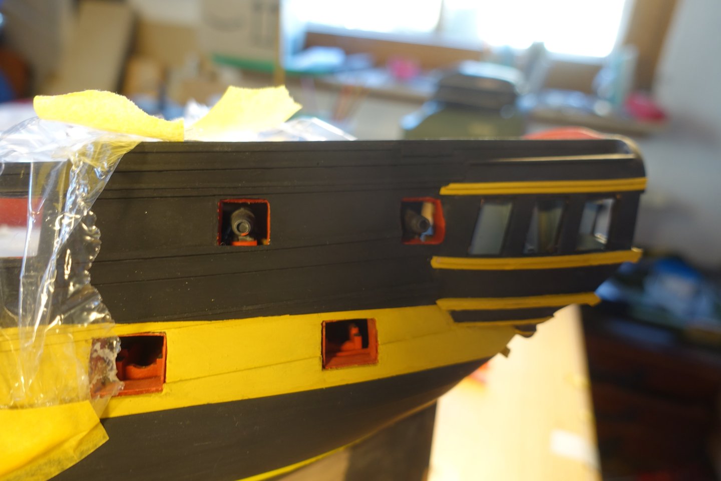
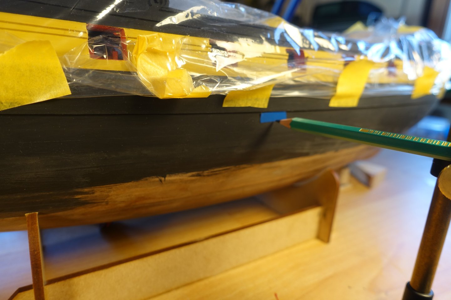
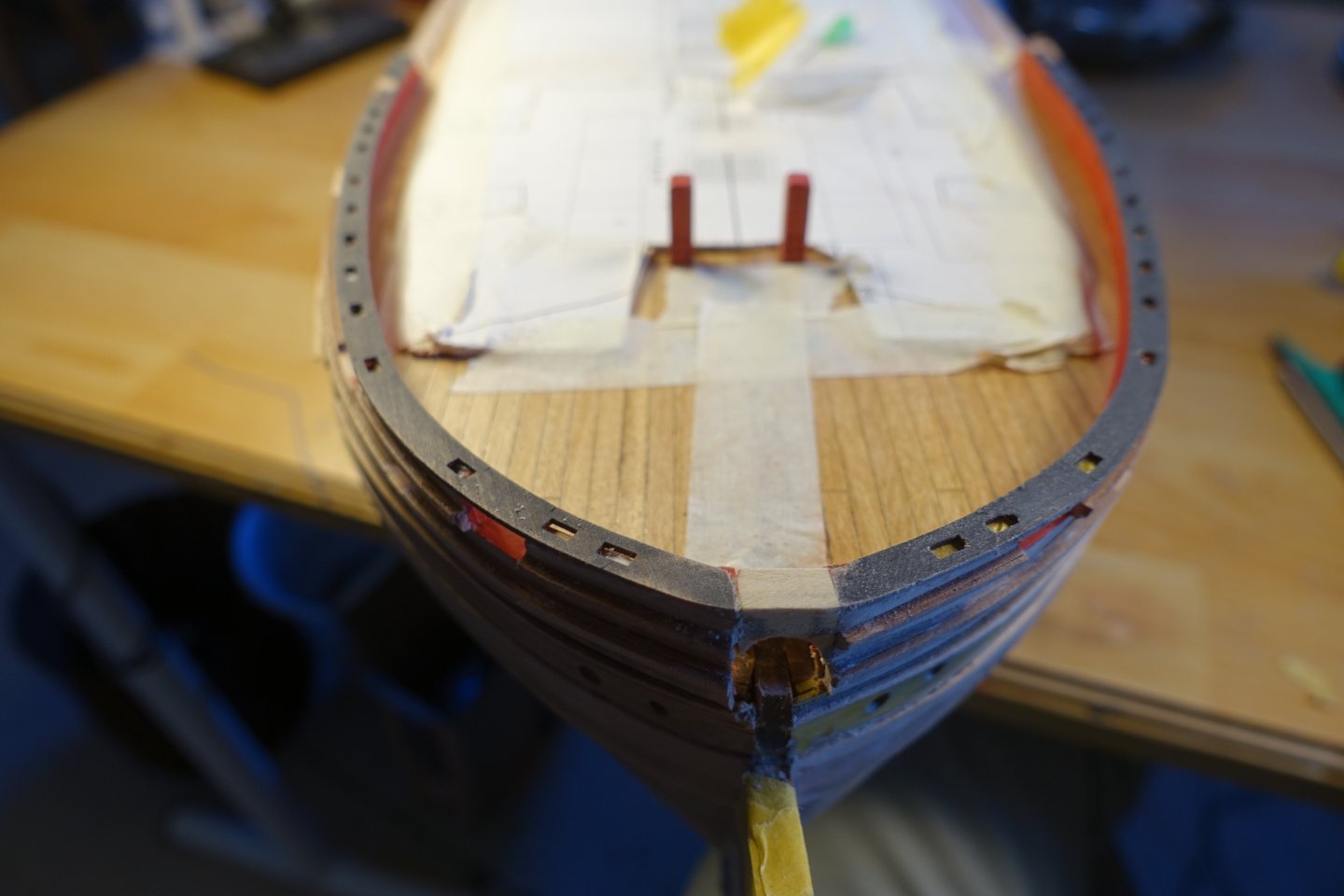
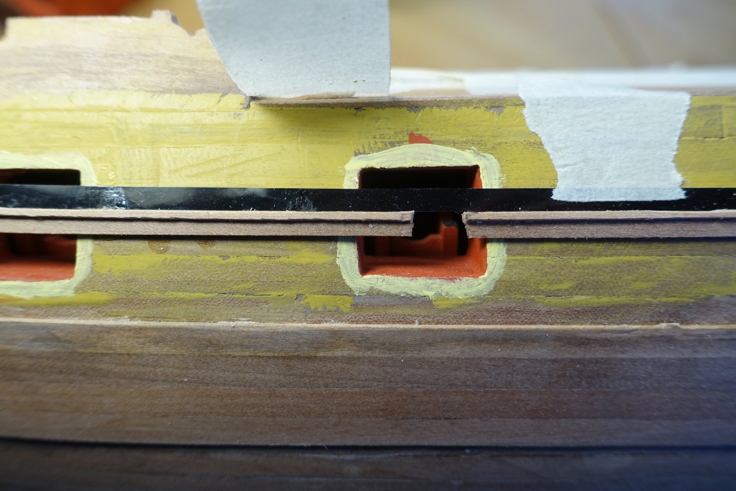
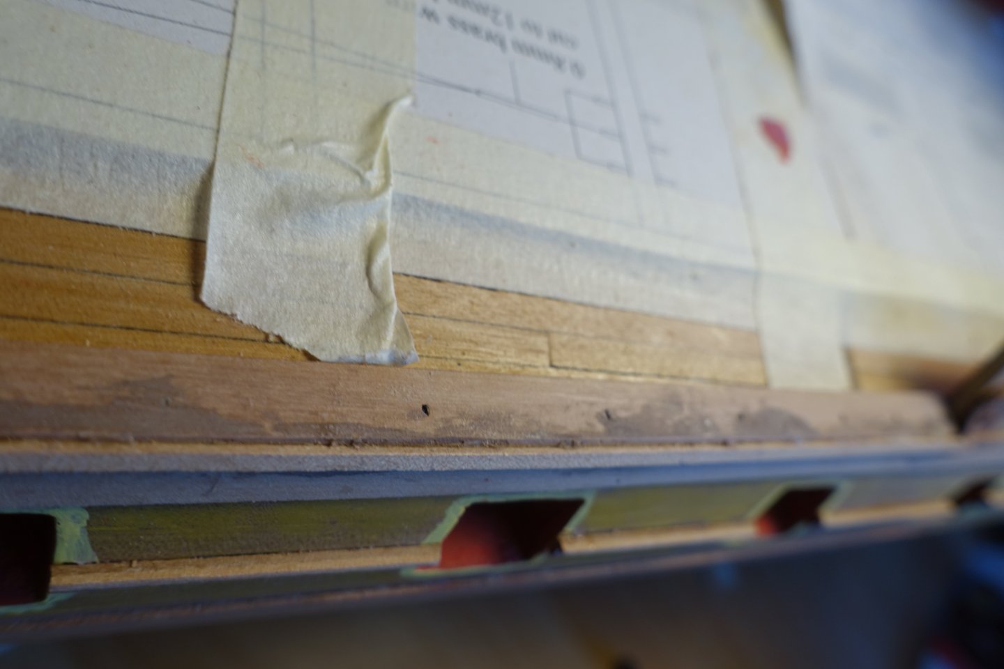
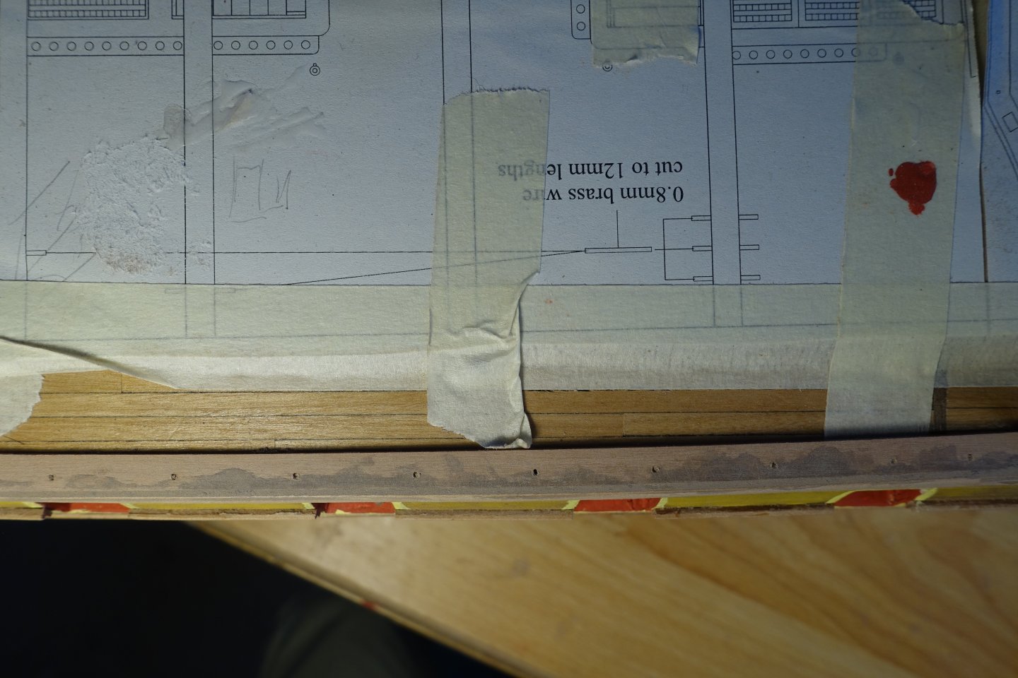
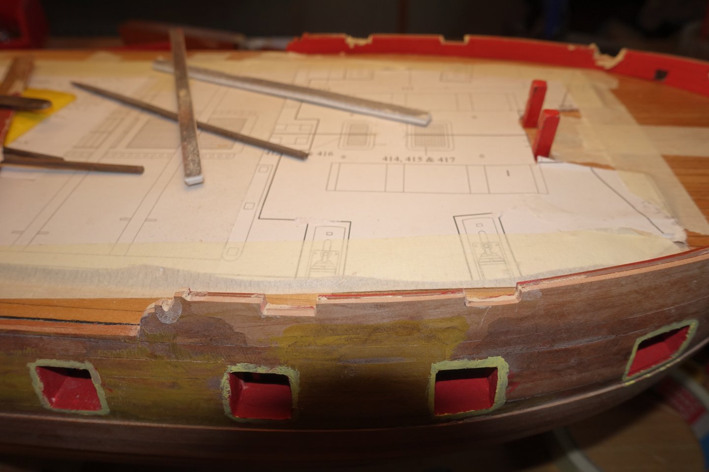
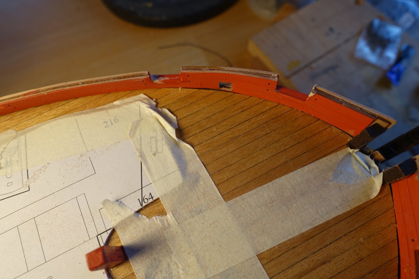
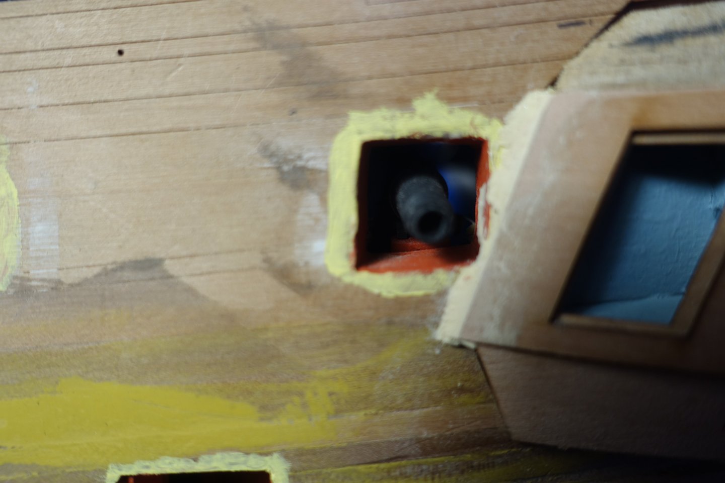
Decorativ strips / wash edge at the bow The strips on the bow only had to be adjusted slightly. After fitting, these were painted, attached to the bow and then covered with cling film. Decorative strips at the stern The decorative strips at the stern were adapted. Among other things, the strips directly above and below the windows of the side gallery were bent with heat. After fitting, these were painted and glued on. Waterline According to the plan, the waterline at the bow is 90 mm from the keel base and 96 mm at the stern. Accordingly, I raised the bow by 6 mm and checked the difference with a remaining piece of 6 mm. Bow: Stern In the centre of the hull, the distance between the waterline and the wale was measured on the plan and transferred to the ship. The waterline was then first marked with a pencil and then re-marked with tape. I am currently trying out the best way to glue the copper plates . I'm not going to use the adhesive copper tape from the kit. I have realised that the copper doesn't adhere so well to CA. Clark


-
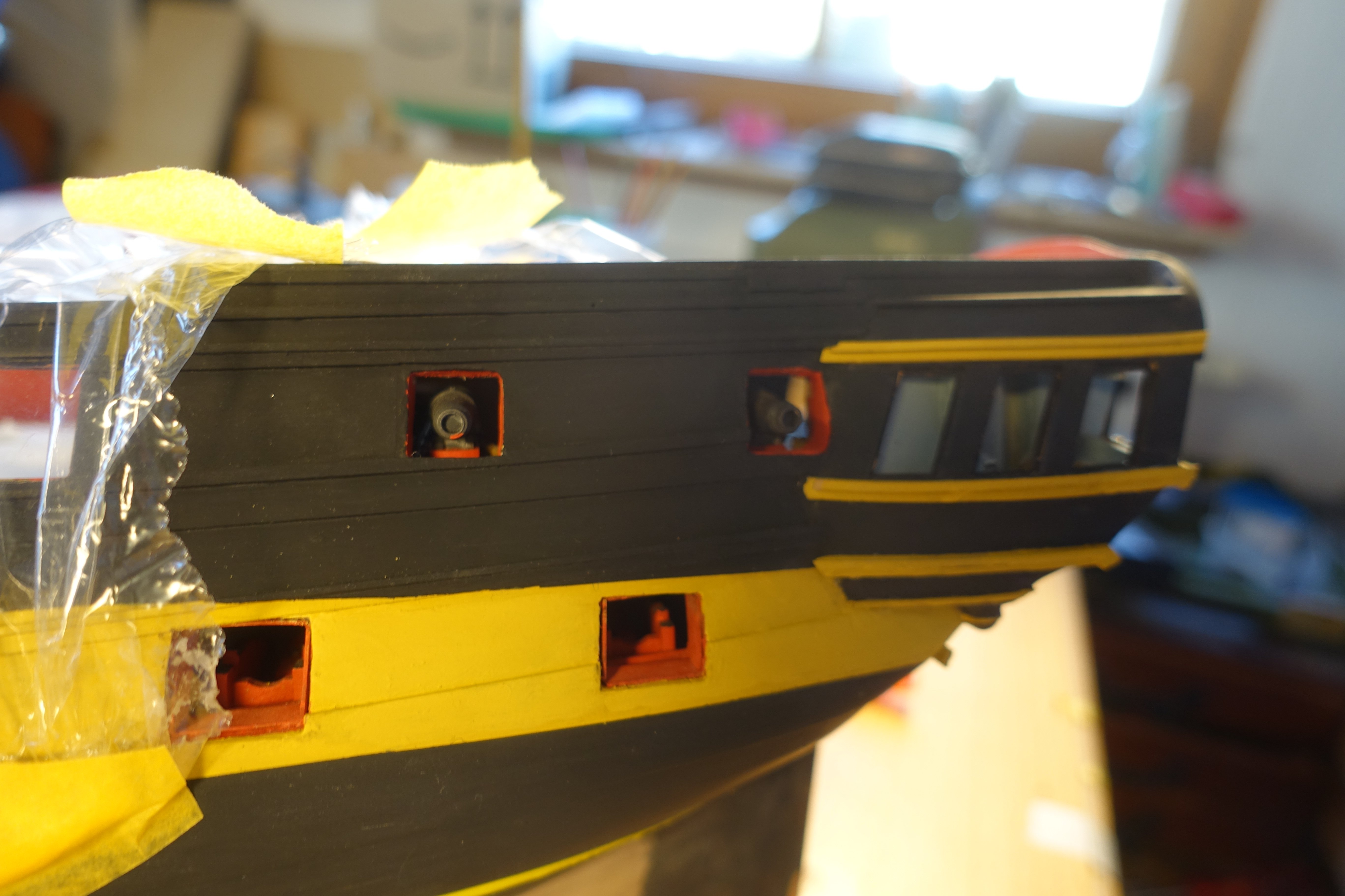
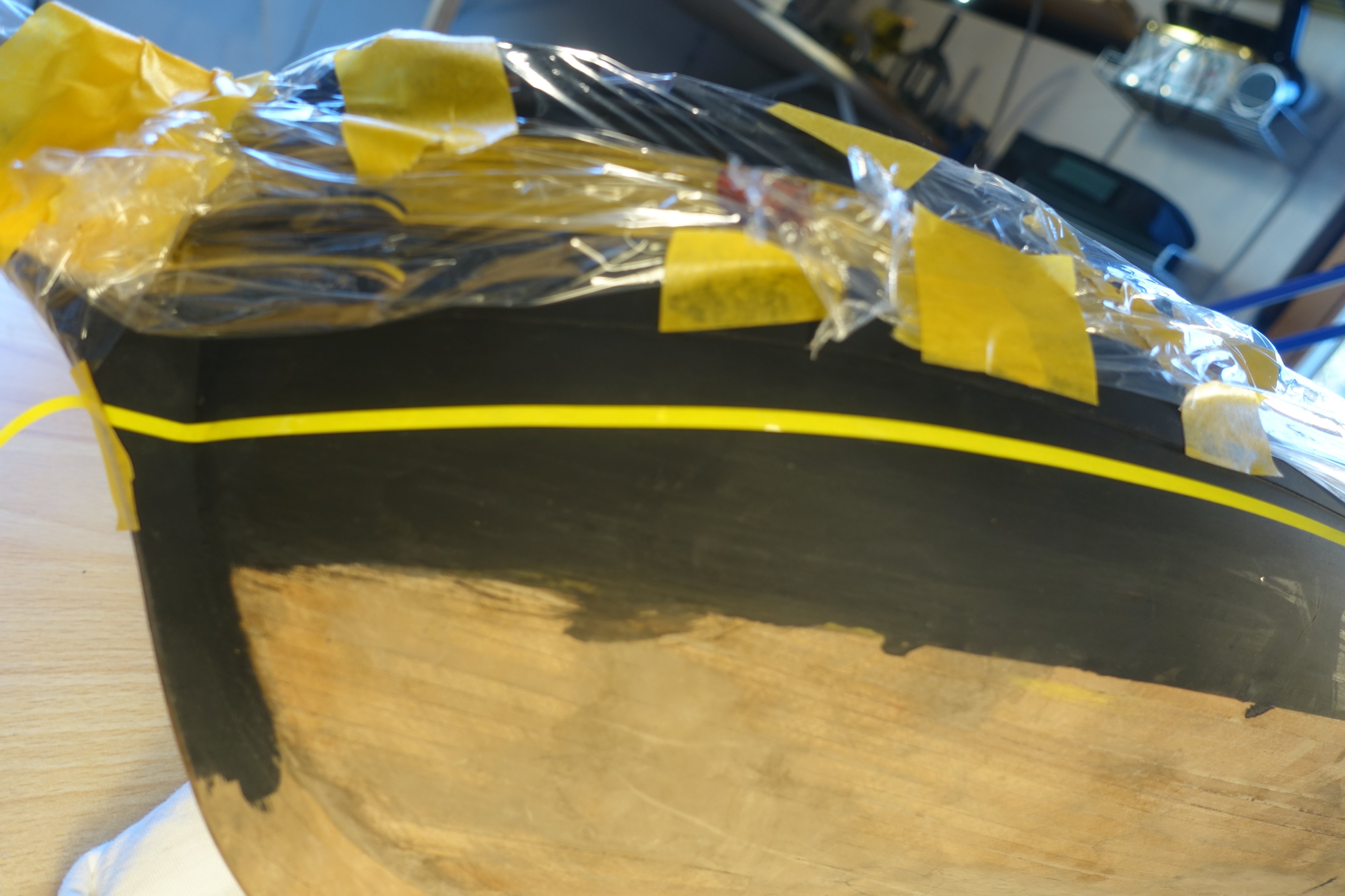
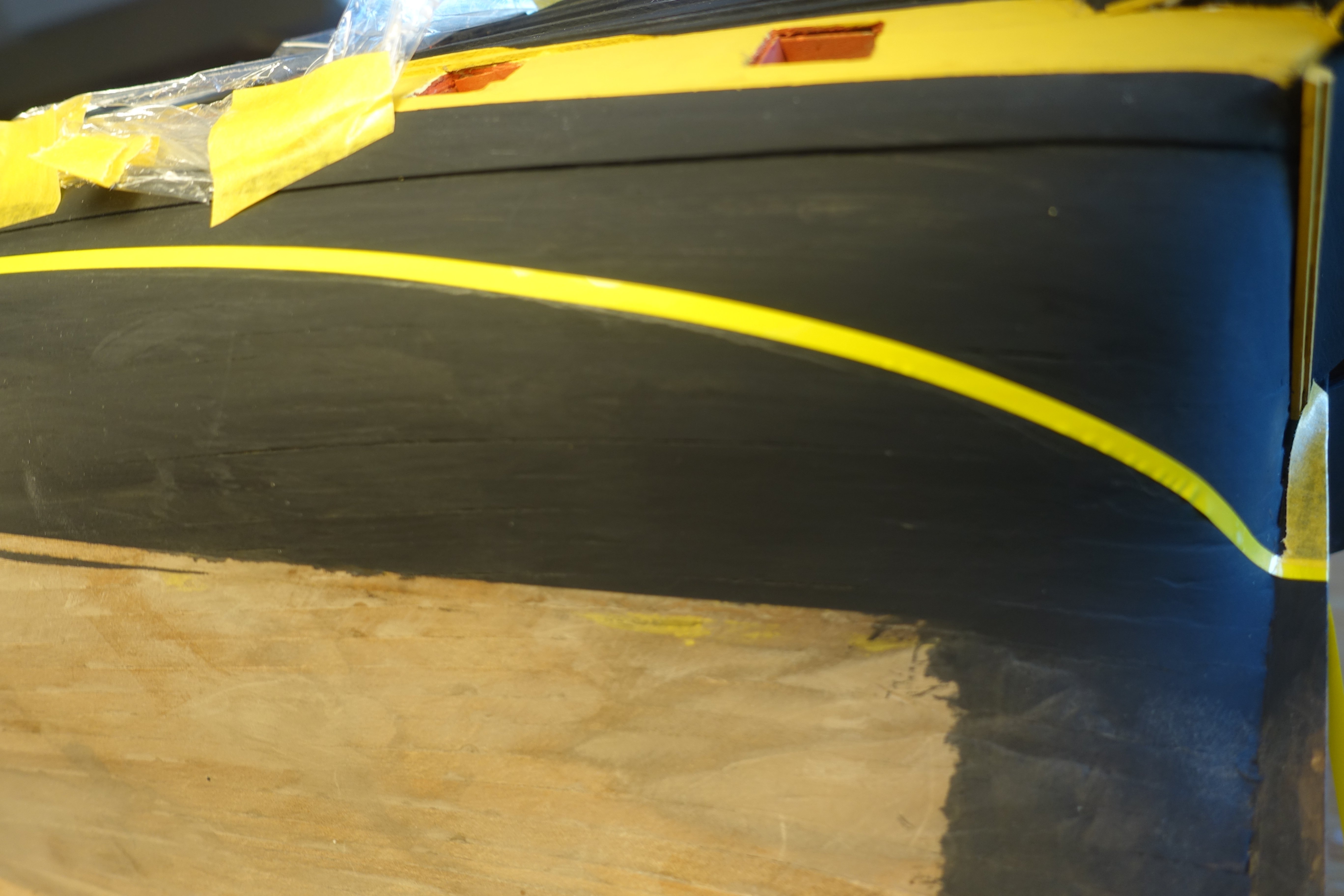
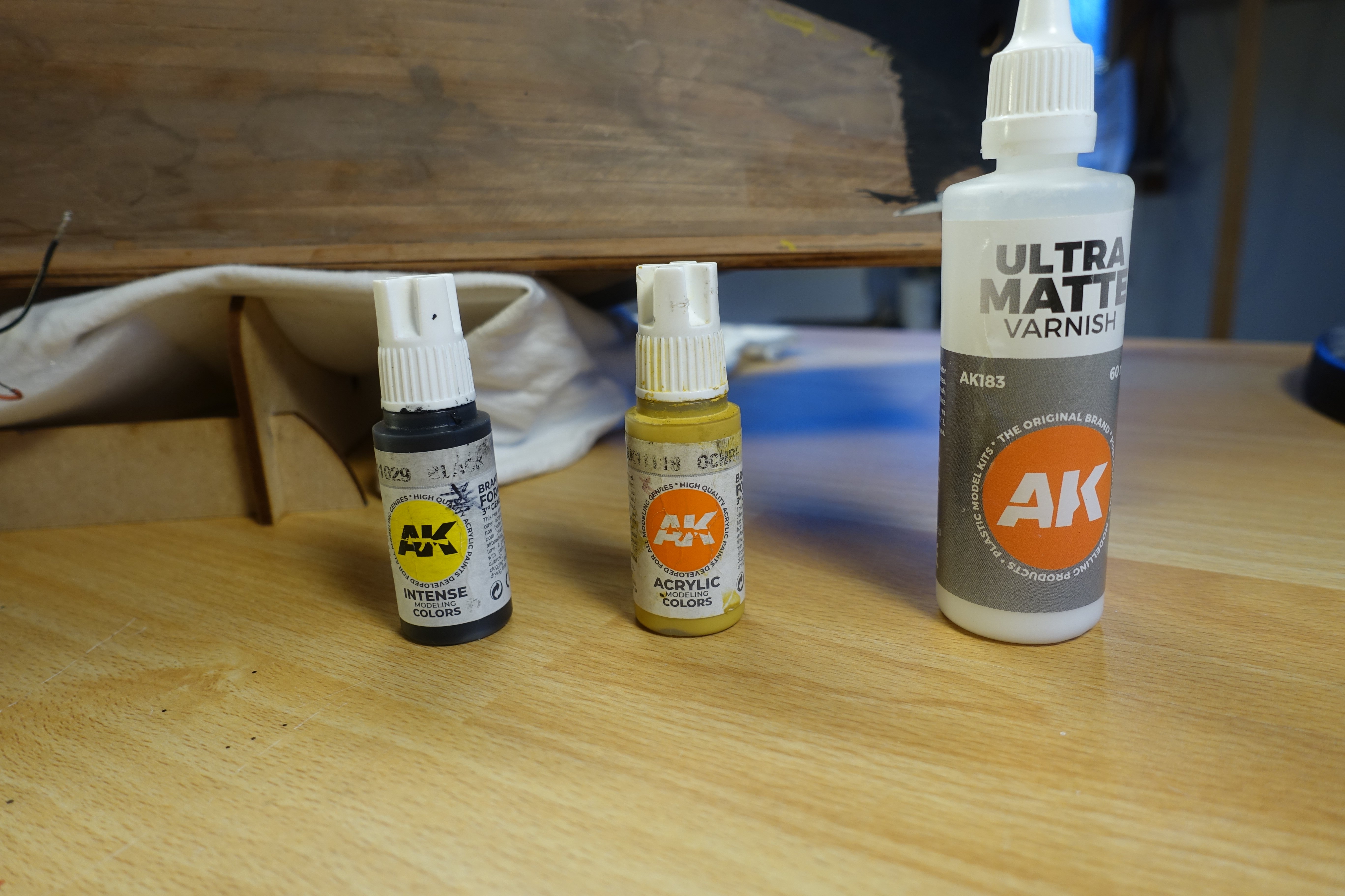
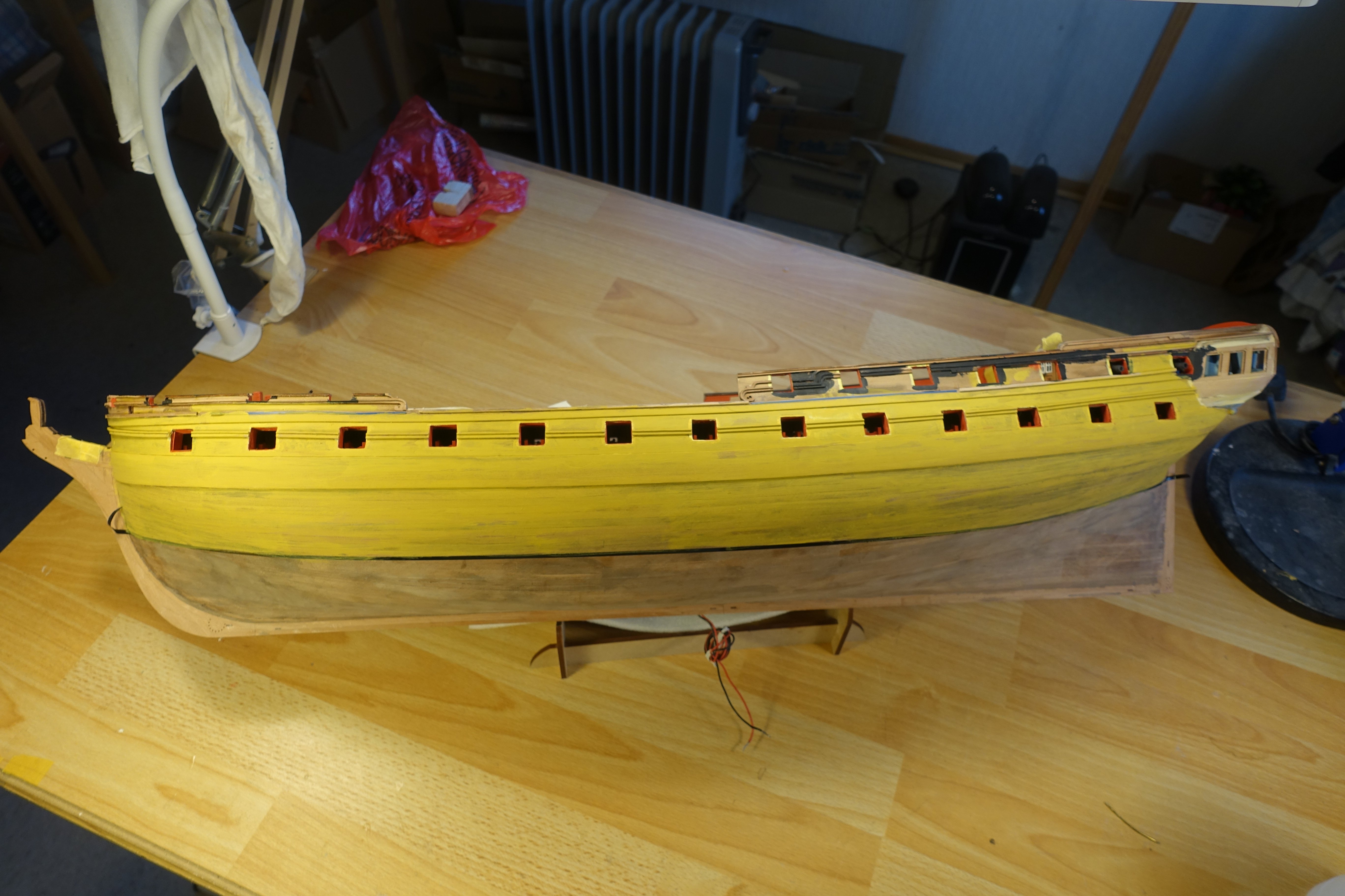
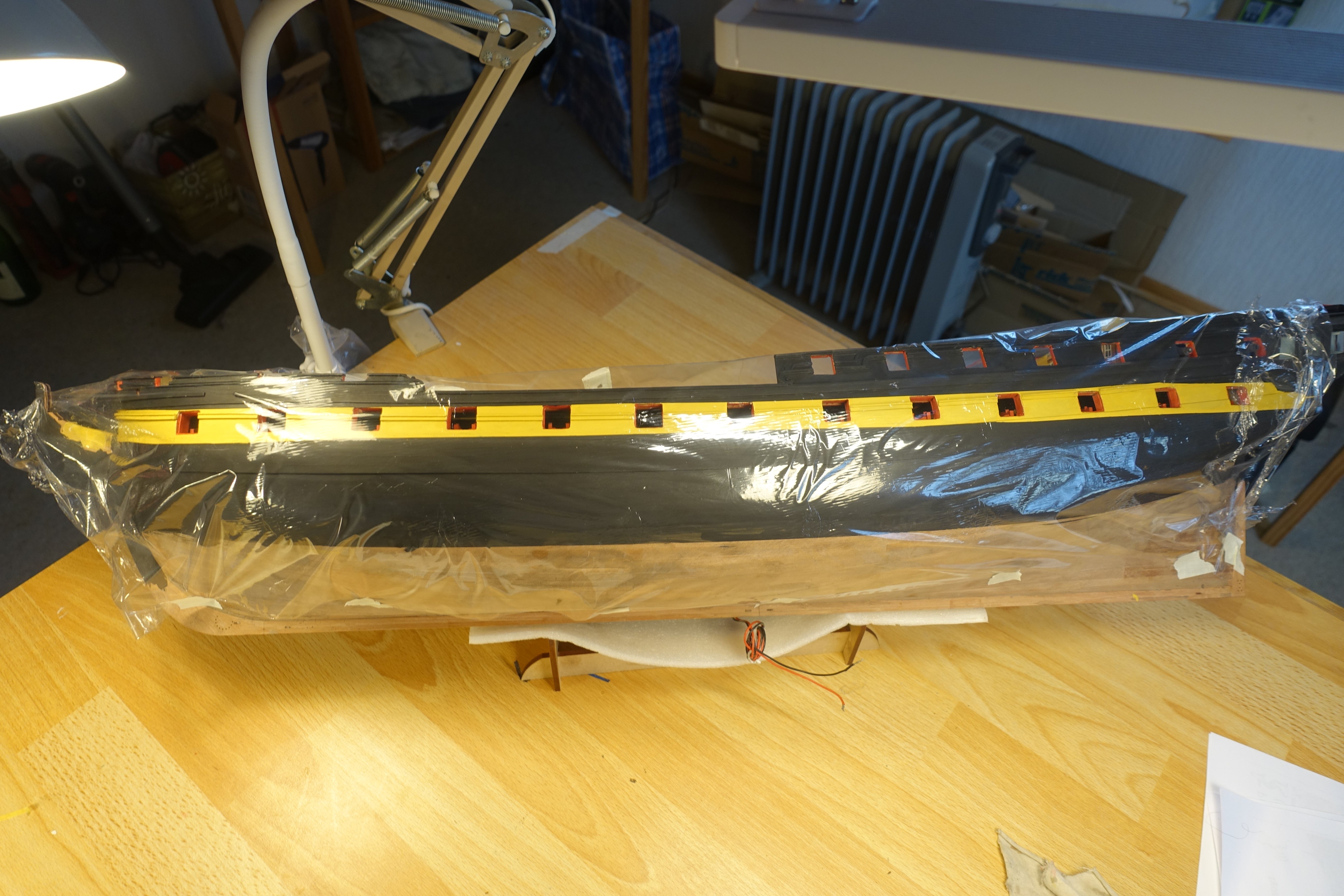
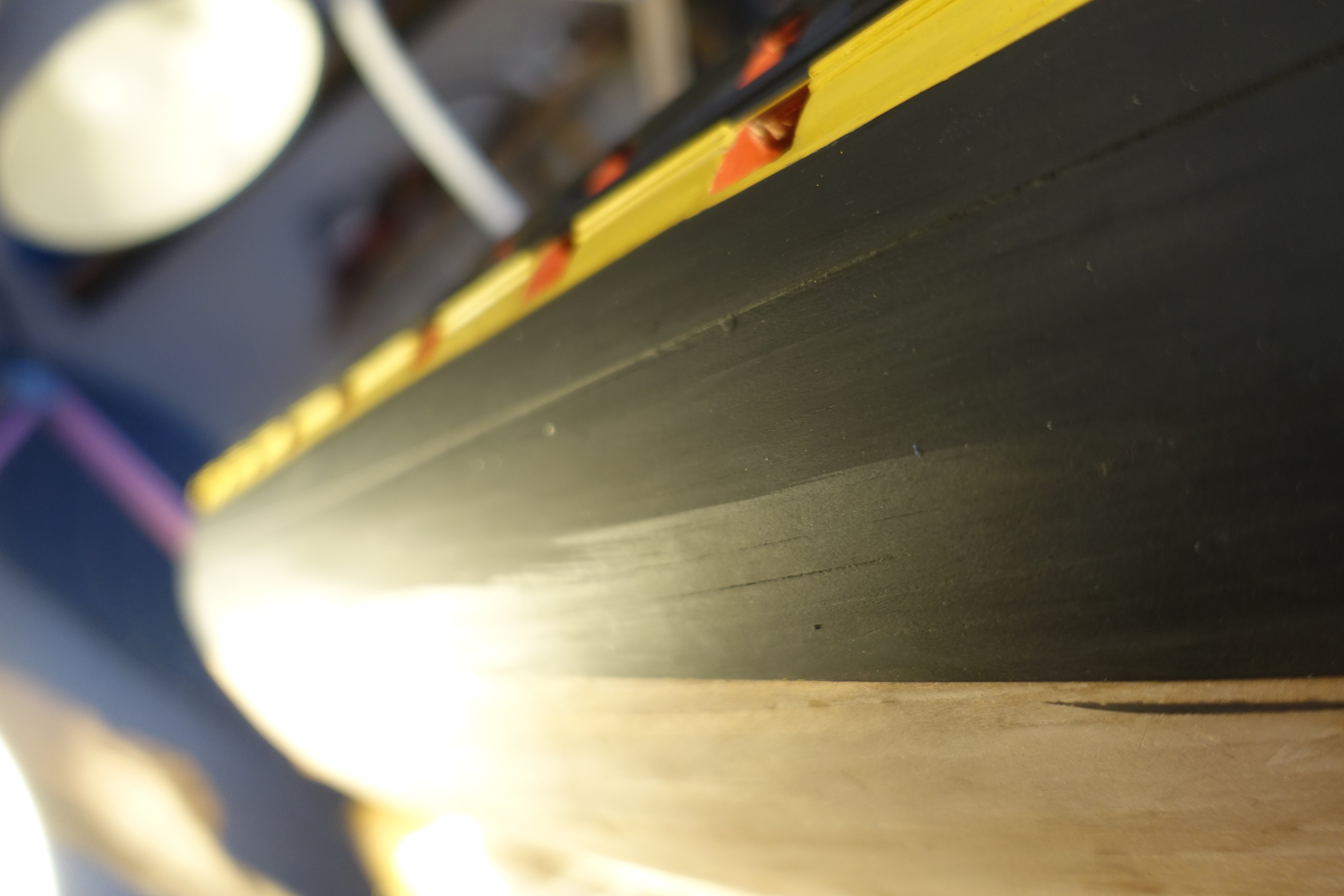
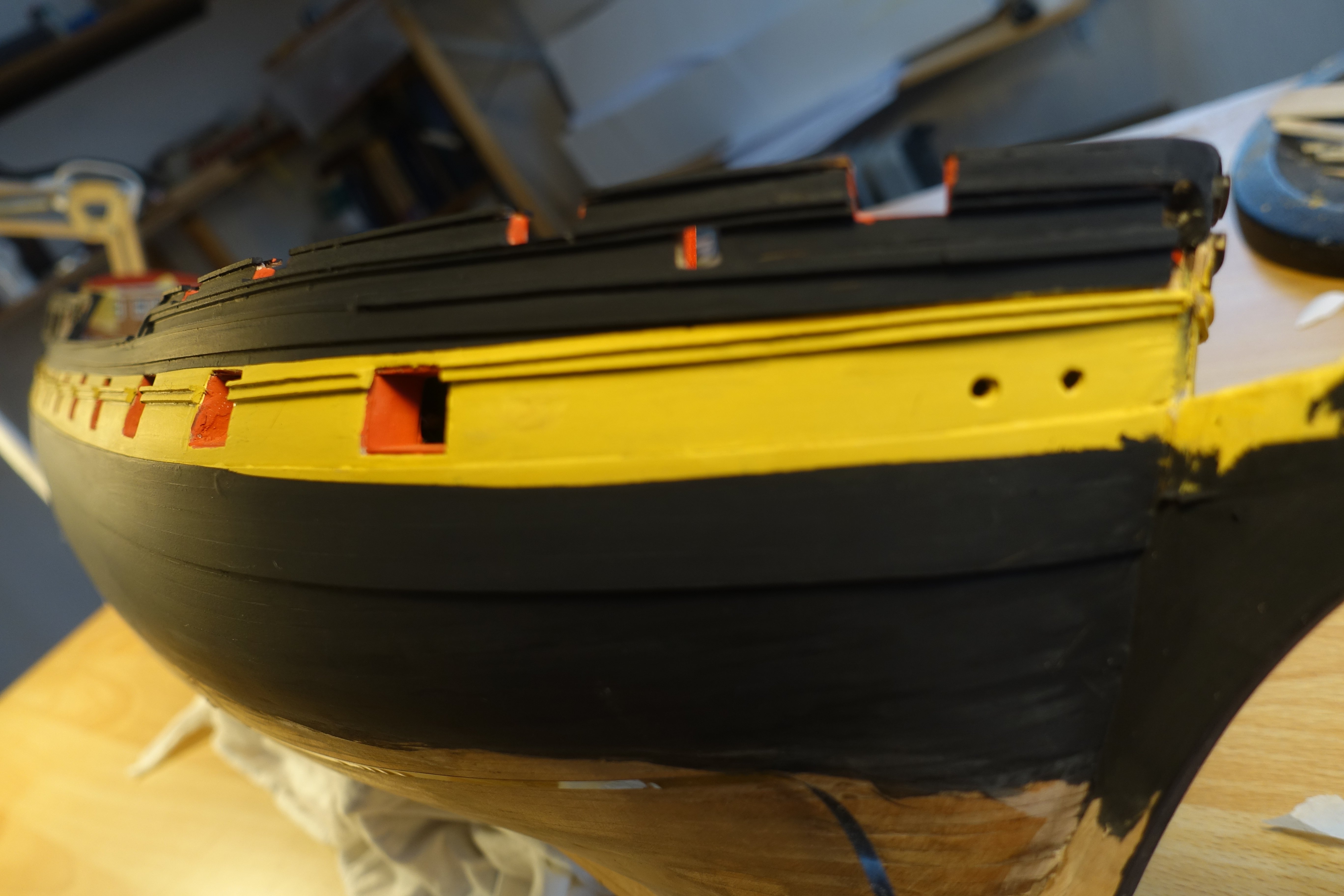
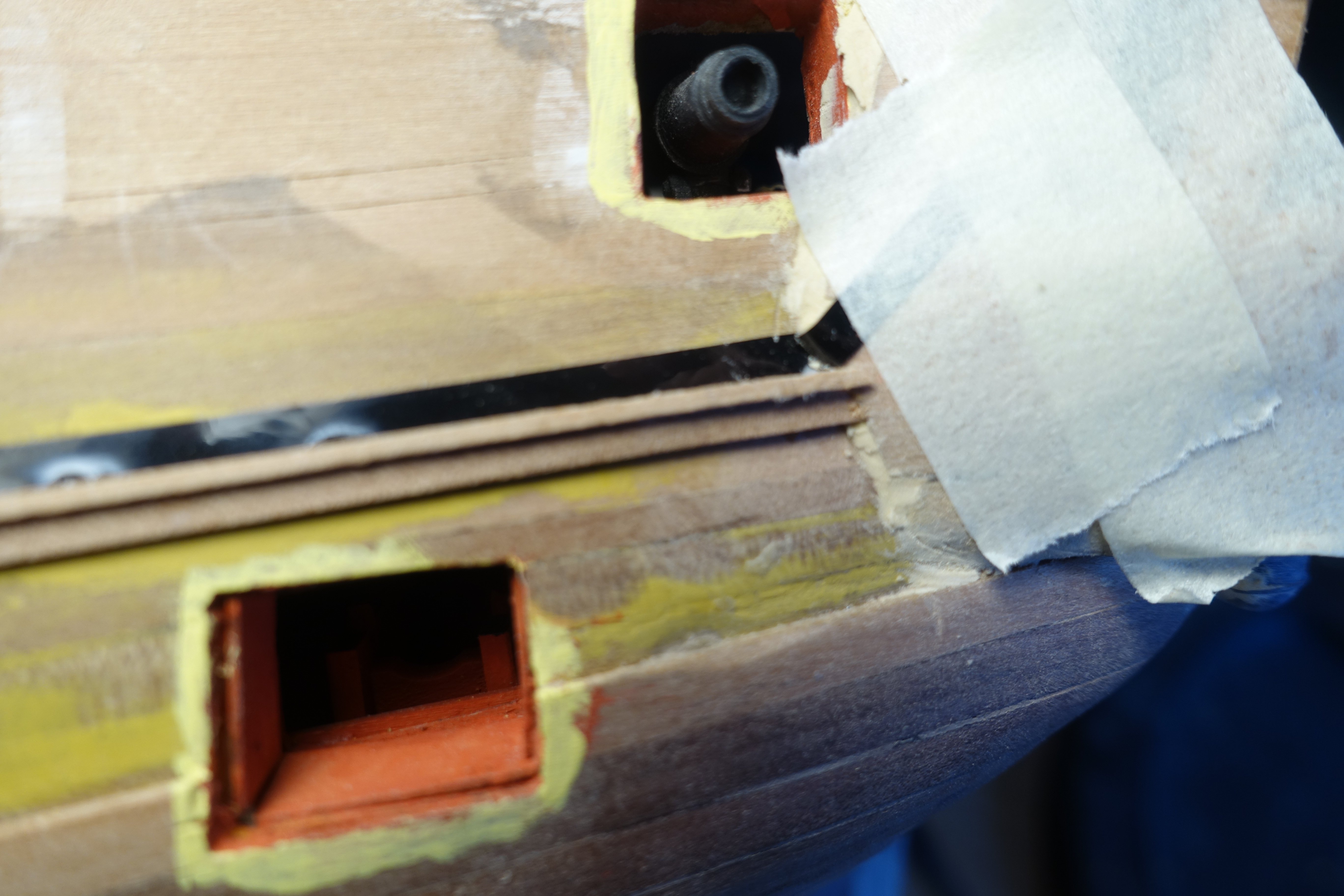
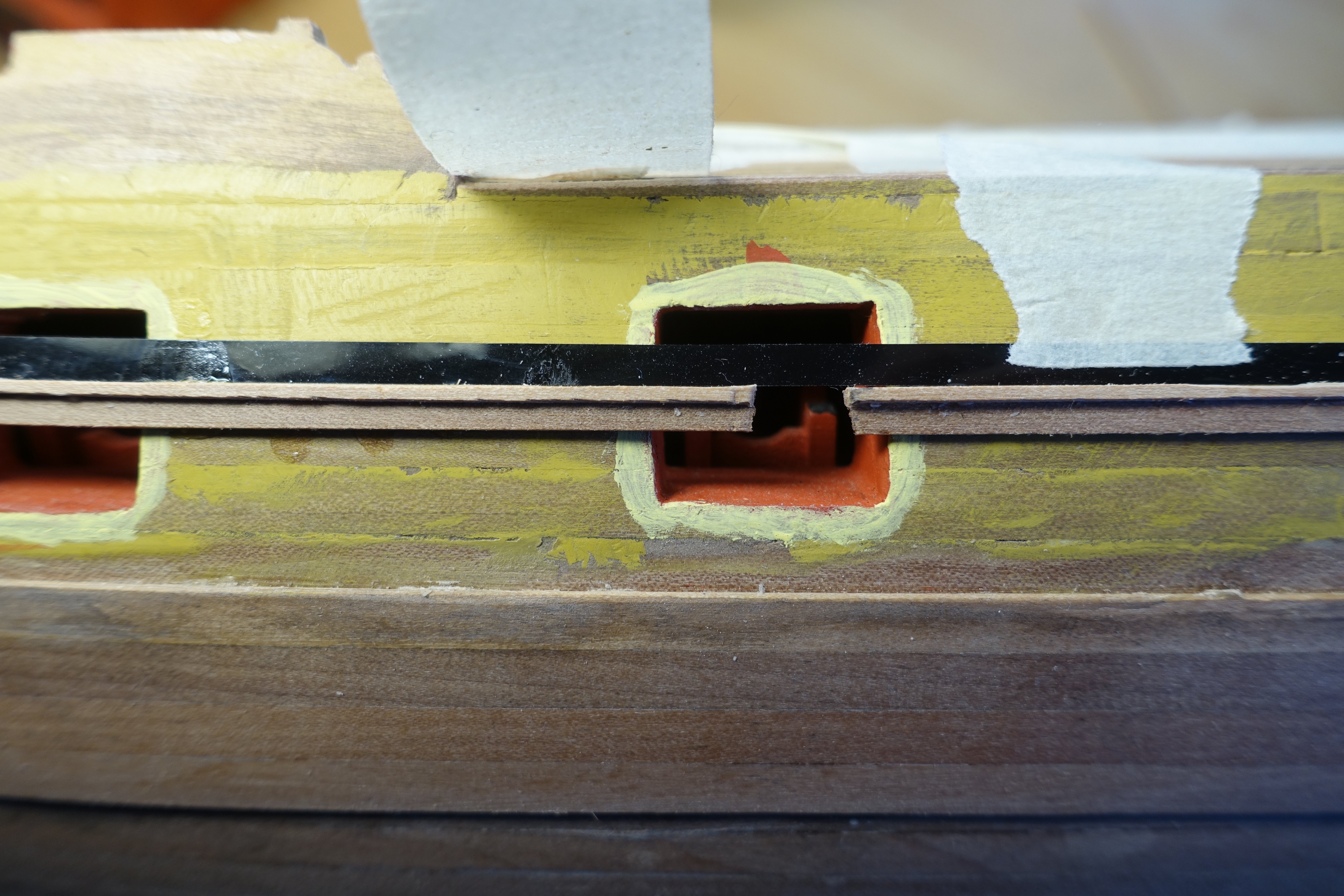
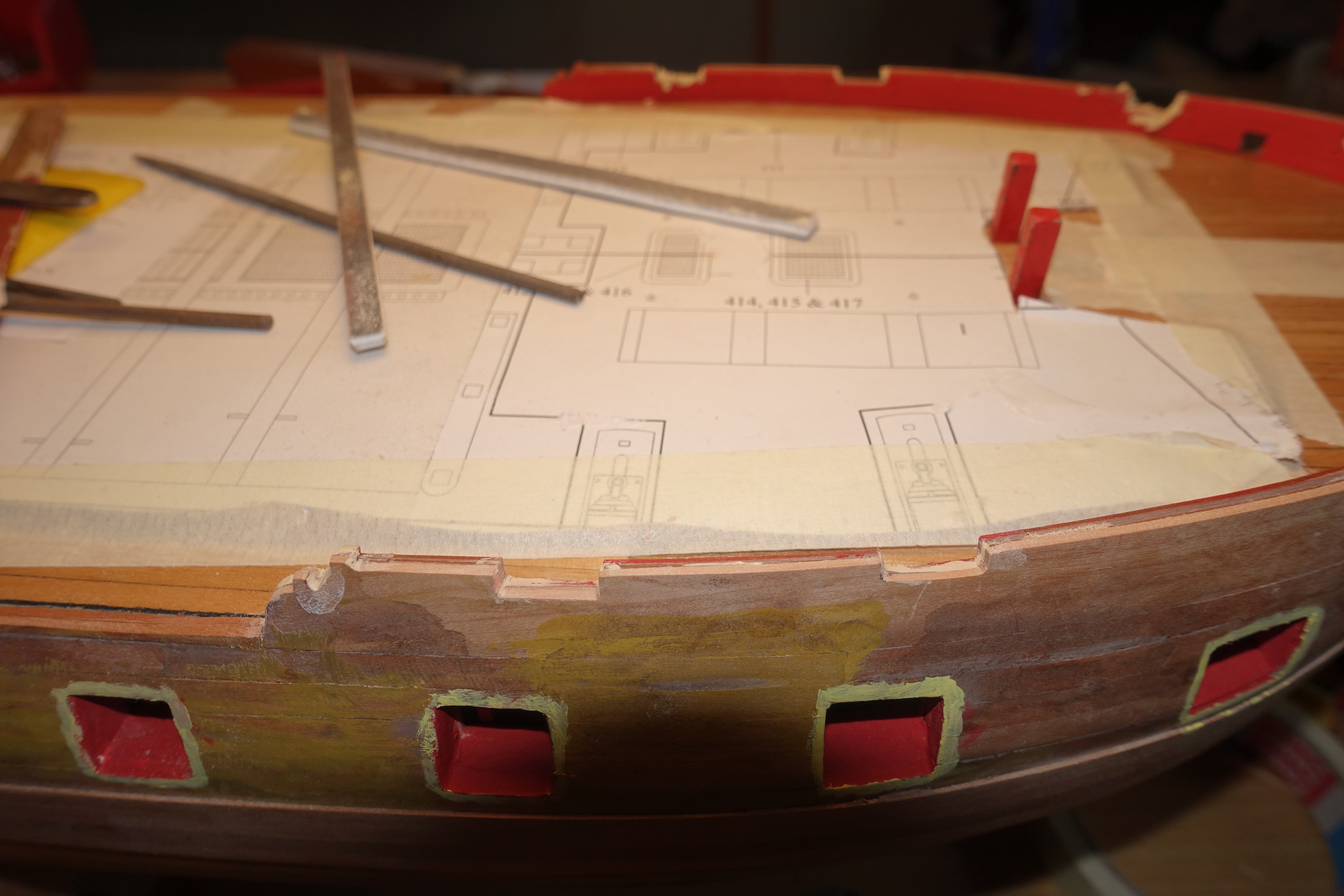
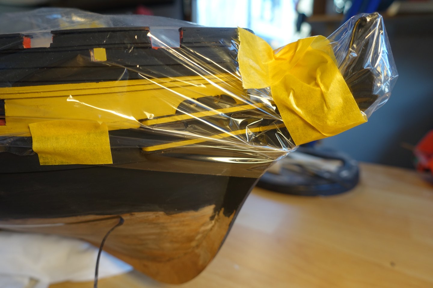
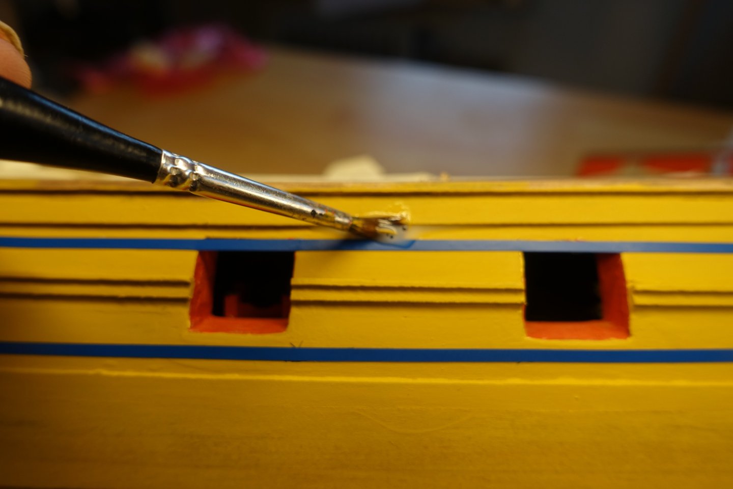
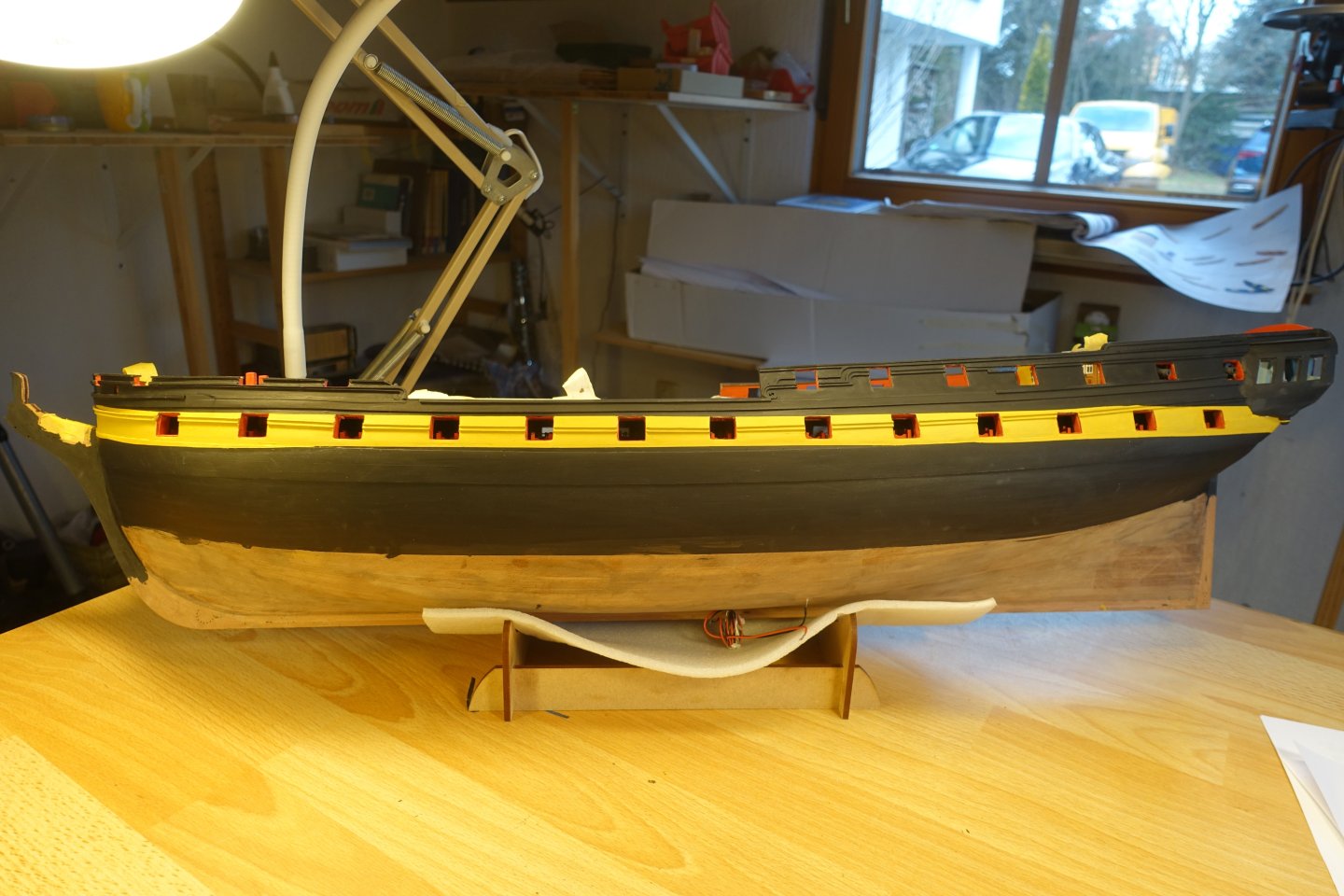
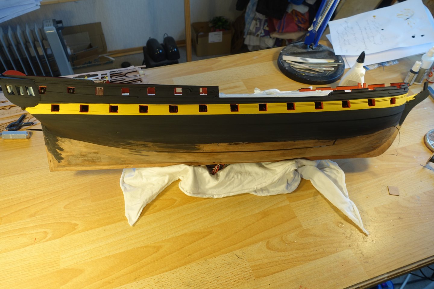
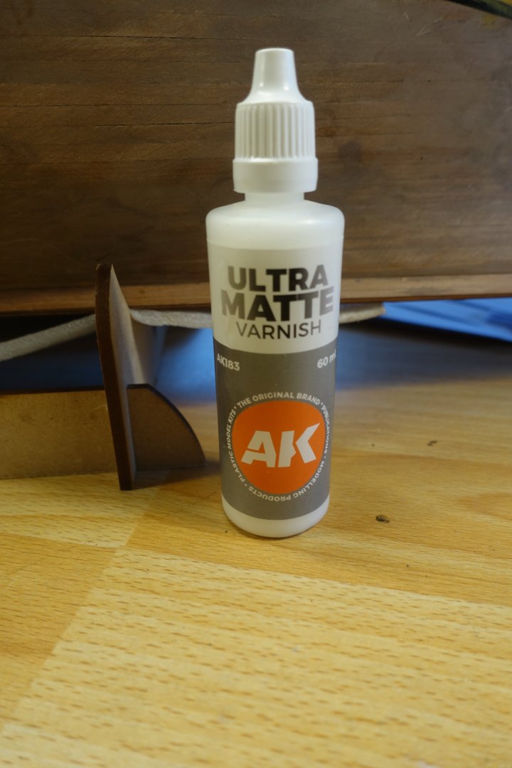
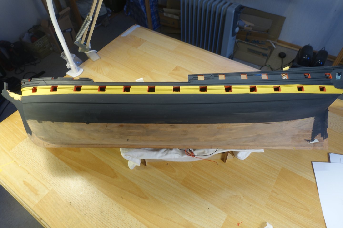
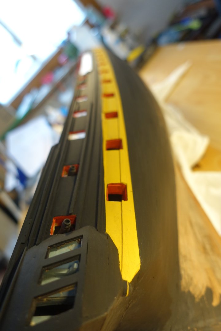
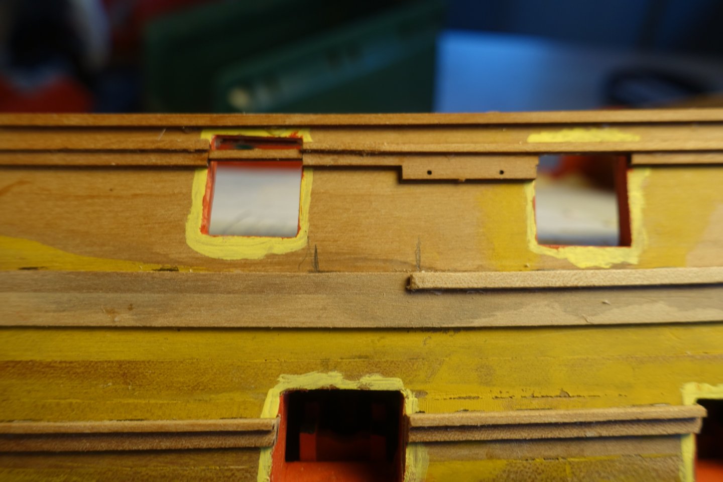
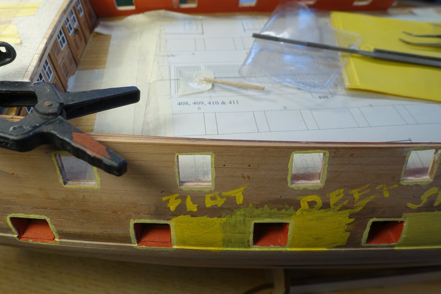
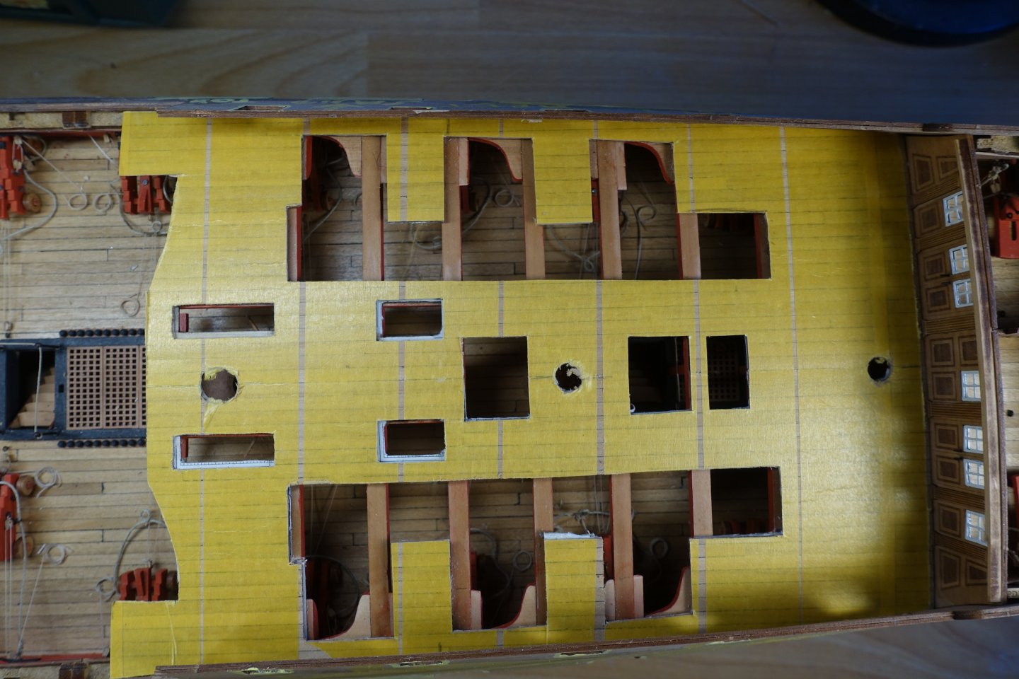
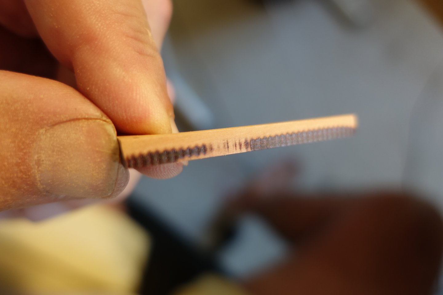
Painting the hull I tried out several shades of yellow and involved my grandchildren in the decision-making process. In the end, we opted for a simple yellow ochre. The paints were diluted heavily with water (approx. 30% water) and then applied in a total of three coats. I don't have an airbrush. First, the ochre yellow was applied and then the (overpainted) red in the gun ports was touched up. To apply the black paint, the yellow areas were masked off according to the plans and the transitions were sealed with matt clear varnish. The large amount in the picture was still being spread. First, the port side was painted black. After applying the black paint, the gun ports were touched up again. Then the side was covered with cling film. 6385 The starboard side was painted. I had the impression that the paint was still too shiny, so I coated the entire paint job with ultra-matt clear varnish. You can see the difference in the photograph against the light. The upper part is coated with ultra-matt clear varnish. The lower third towards the keel is only painted with black paint. The ship after completion of the painting. 6388 Next, the decorative strips have to be attached to the stern and the stem post.


-
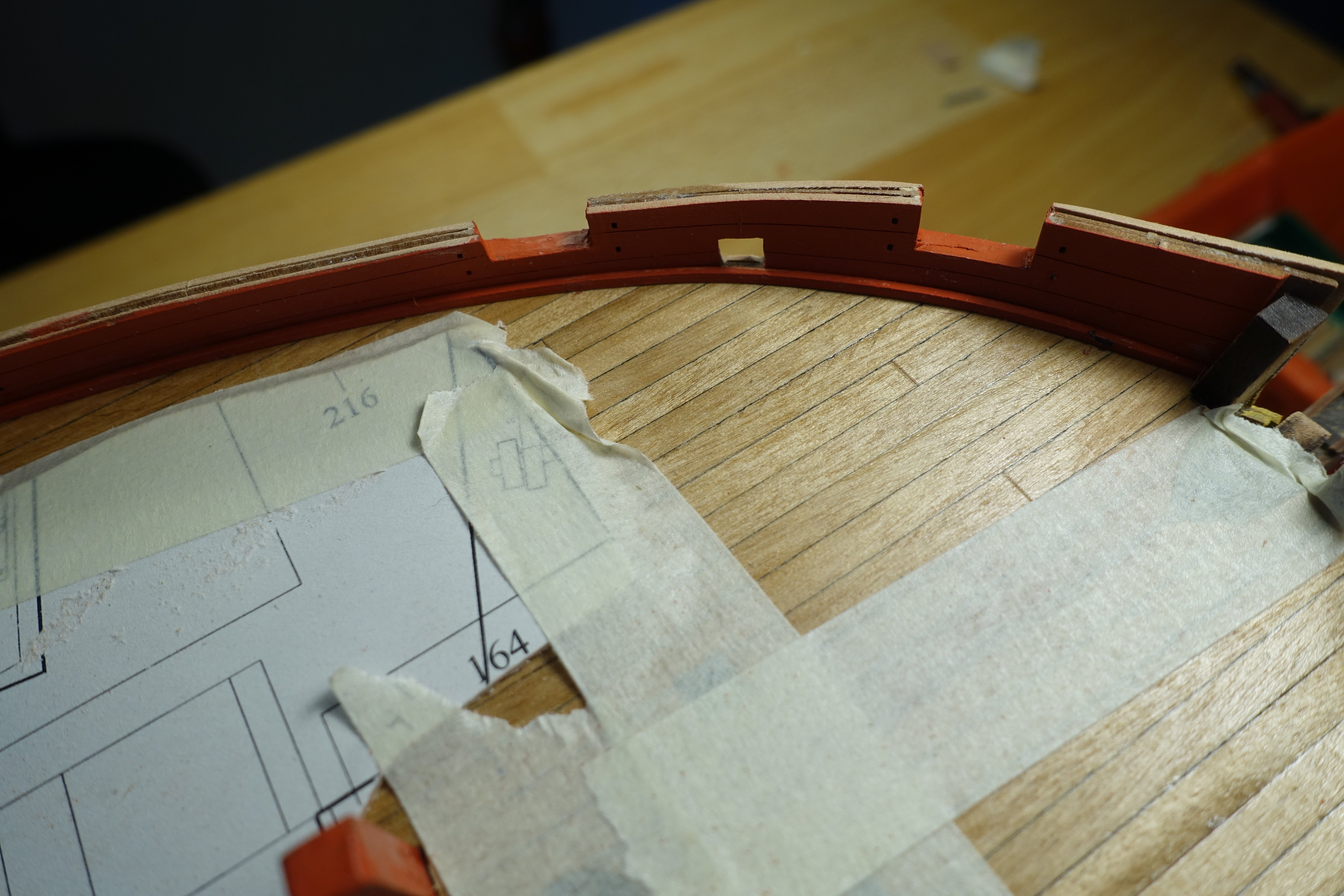
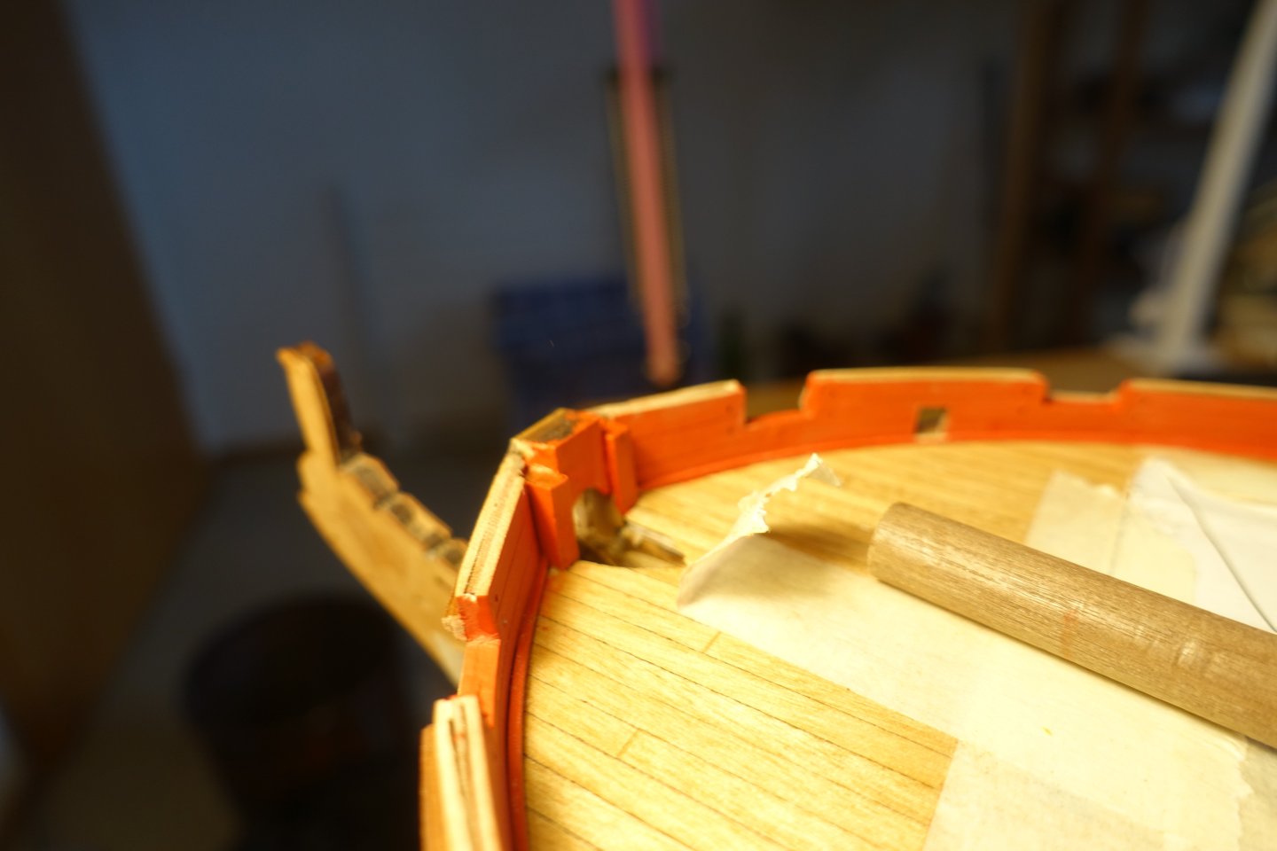
Gunwales To attach the gunwales, I applied PVA and CA alternately. The gunwales of the poop deck were applied flush with the inside. The bow end was slightly bevelled to create the transition to the bulwark. The gunwales of the quarterdeck were applied with the same overhang on the inside and outside (overhang estimated by eye). There is no adjacent upper decorative strip on the forecastle, so the overhang is correspondingly larger. For adjusting the forecastle gunwales, I used a strip approximately 2.4 mm wide and 1 mm thick to standardise the overhang. These were applied to the outside and then the gunwales were glued flush with them. At the bow end, the gunwales were adjusted to fit the inserted filler piece. Next, the planking on the hull must be checked again before painting and copper plating can begin.


-
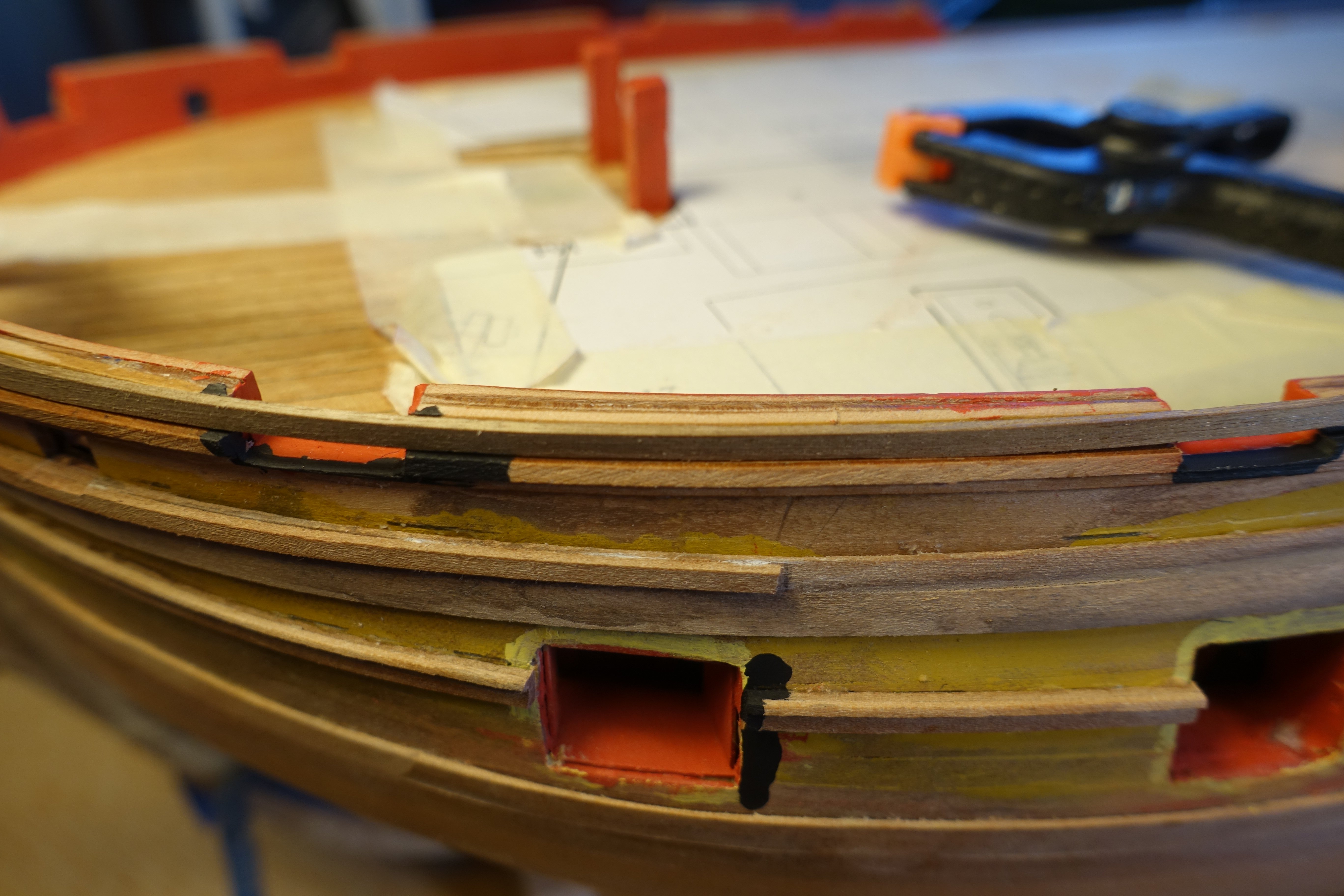
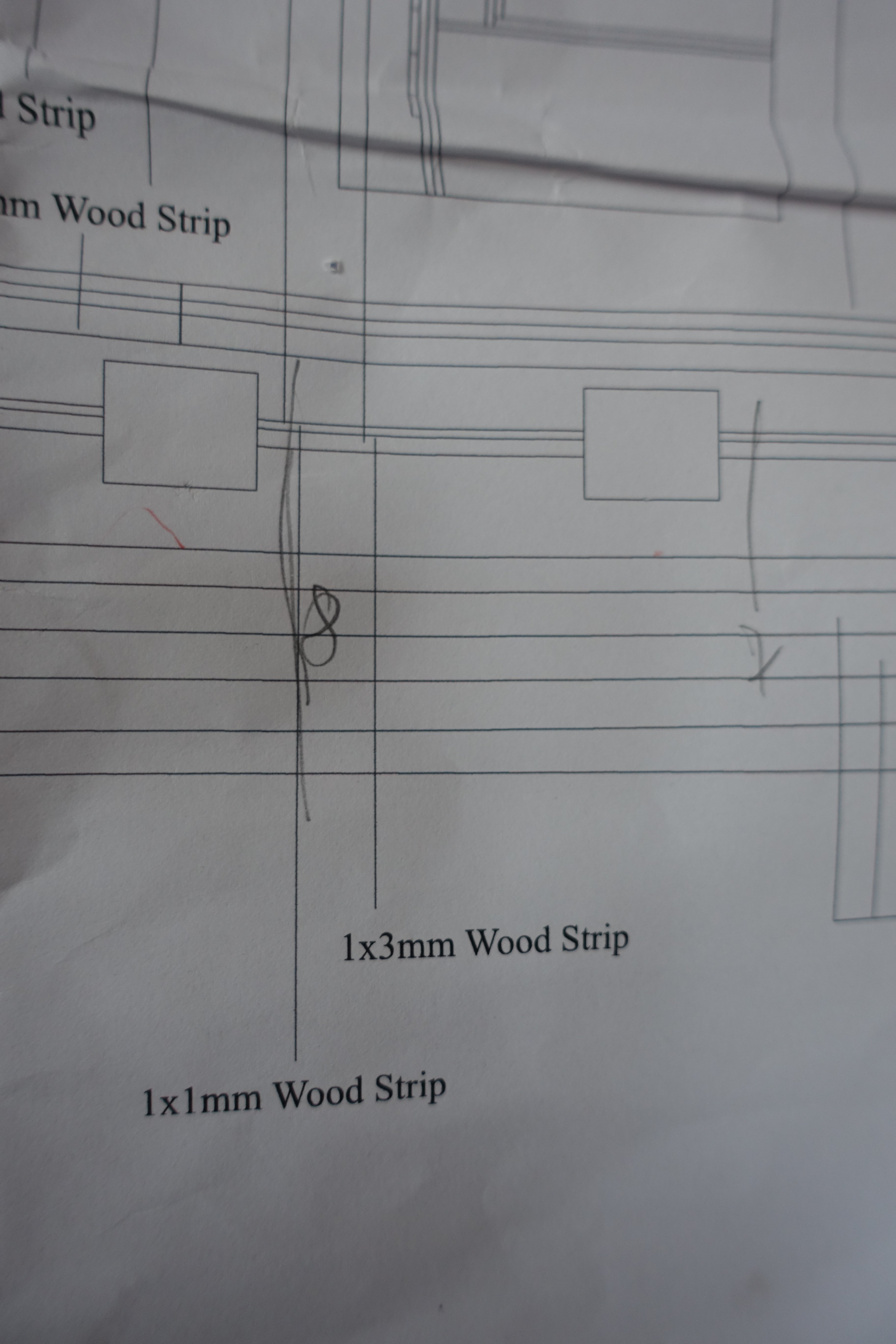
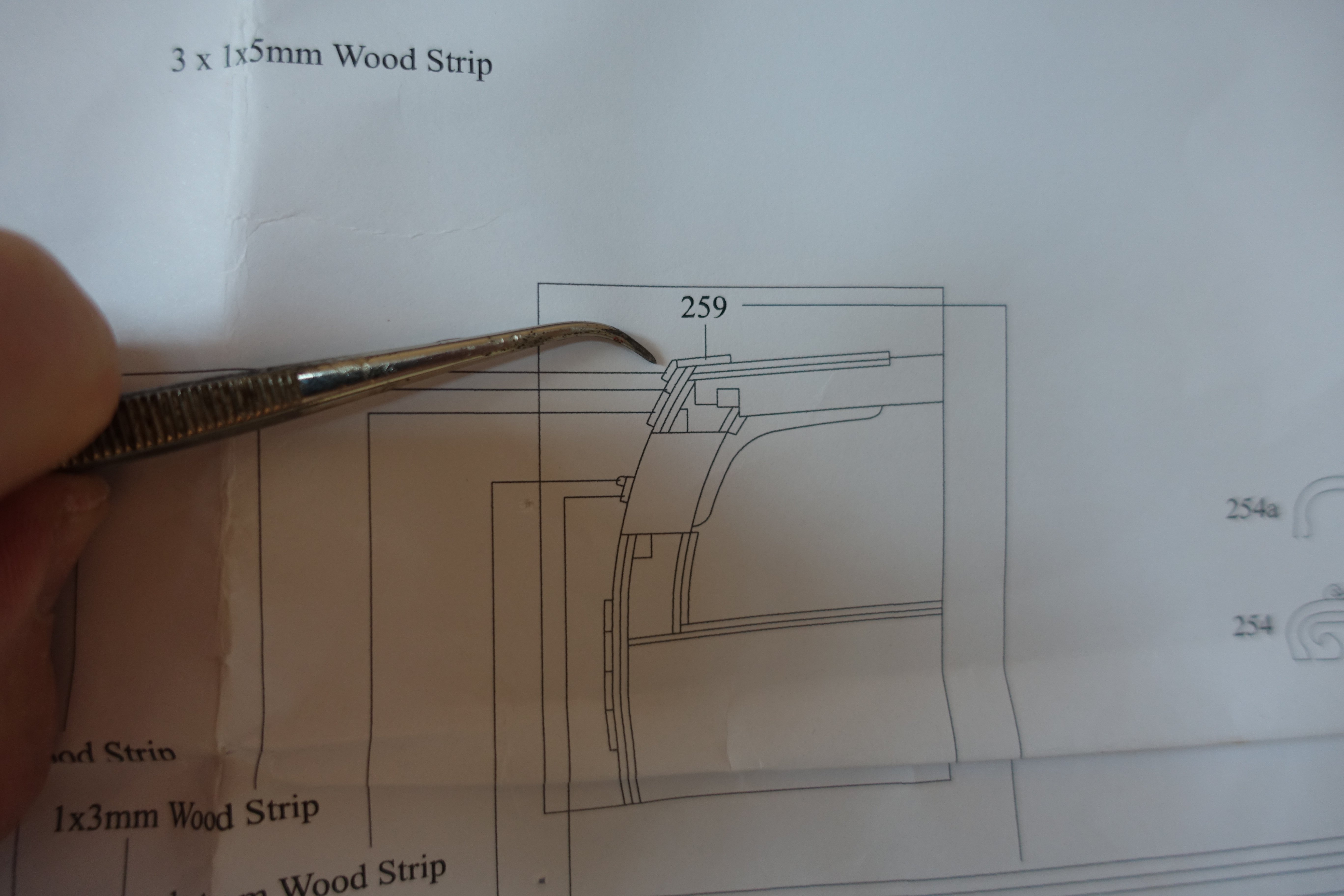
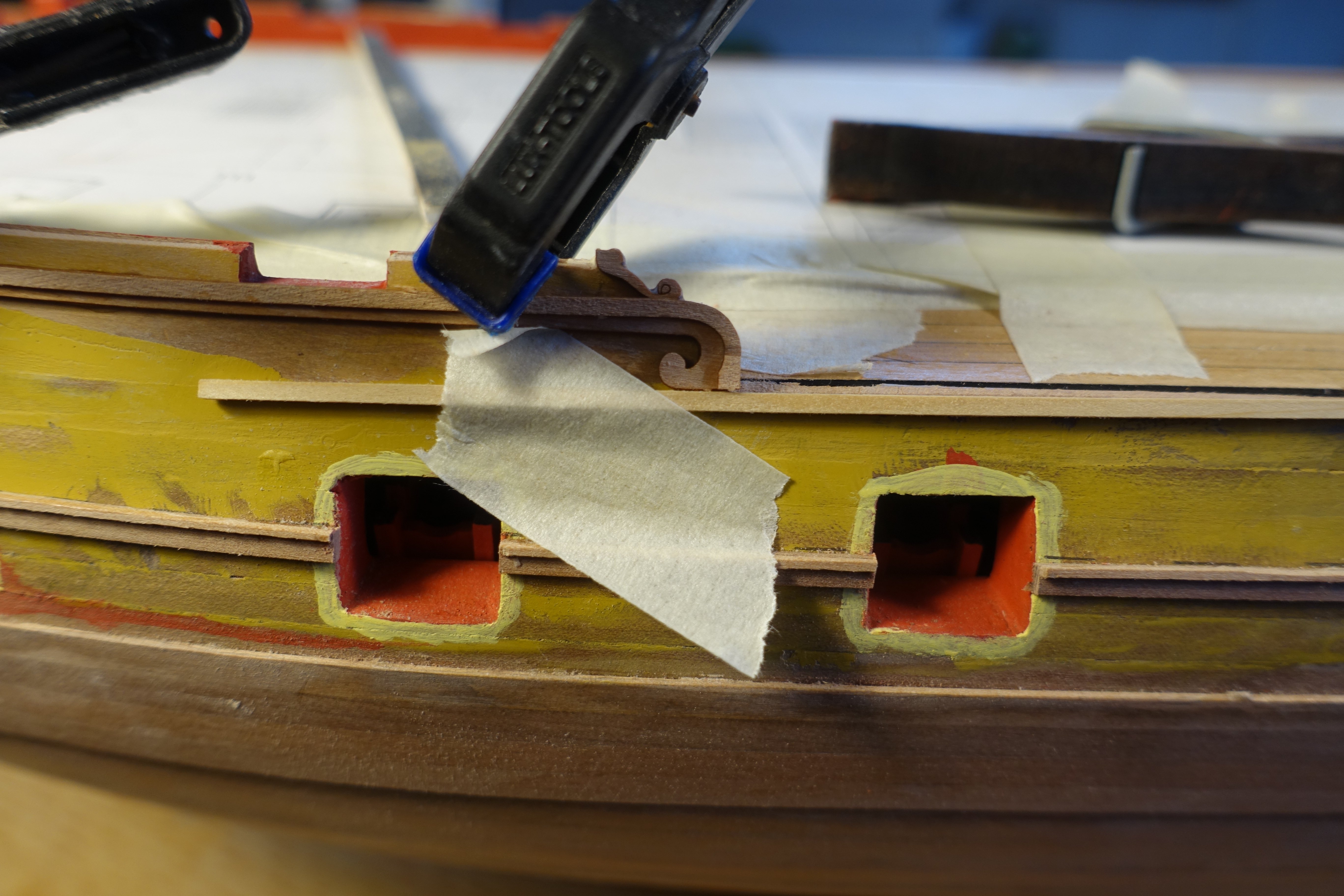
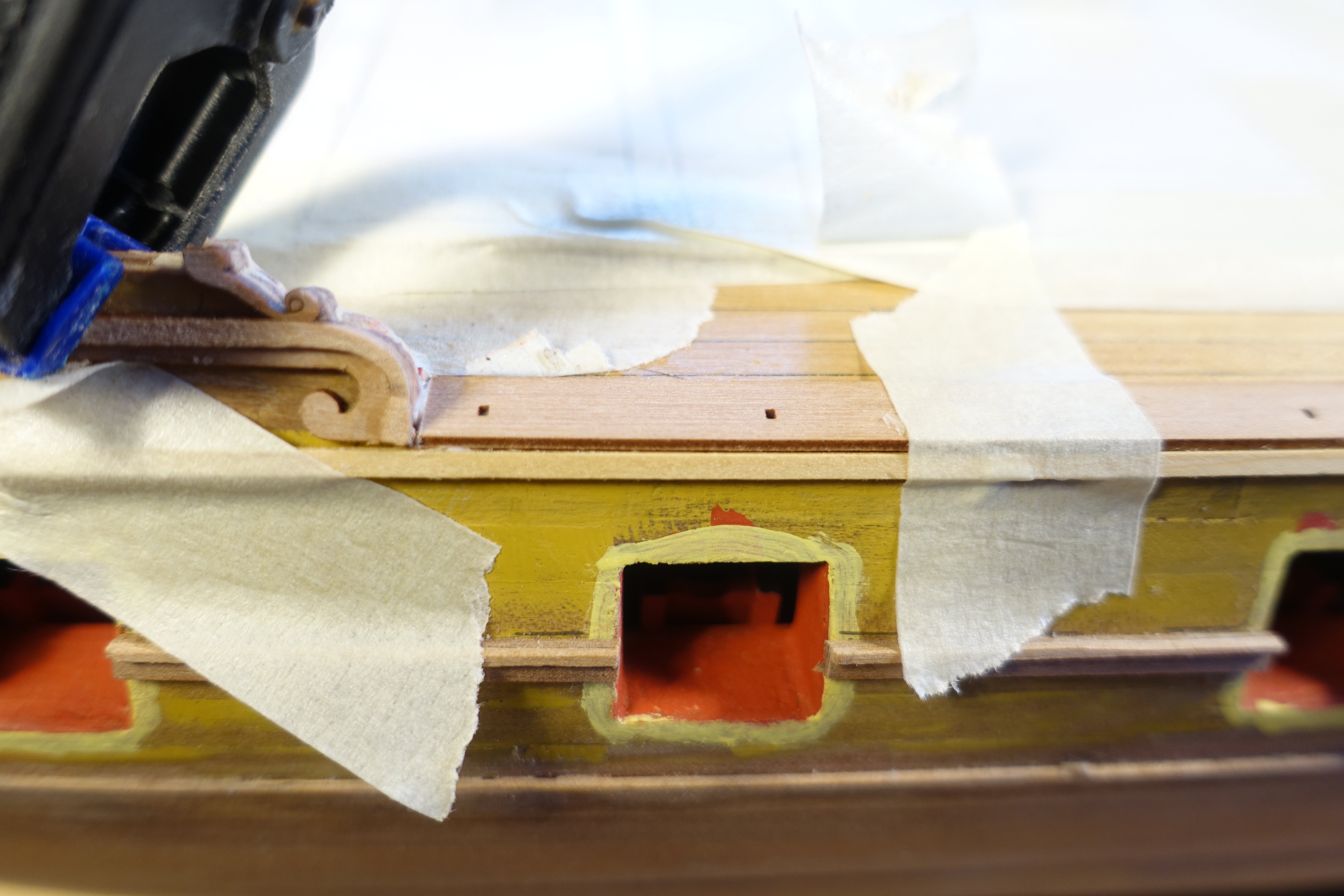
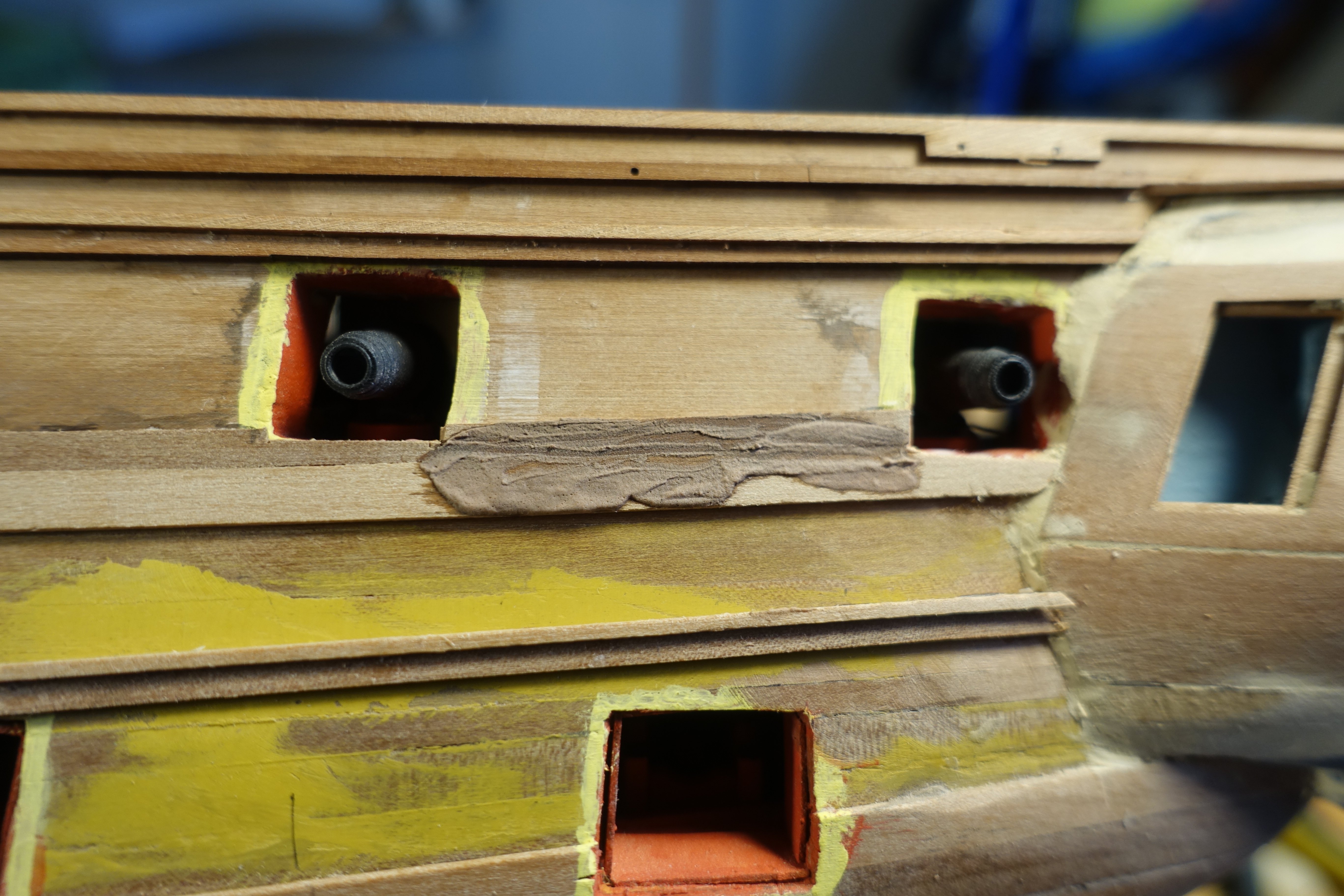
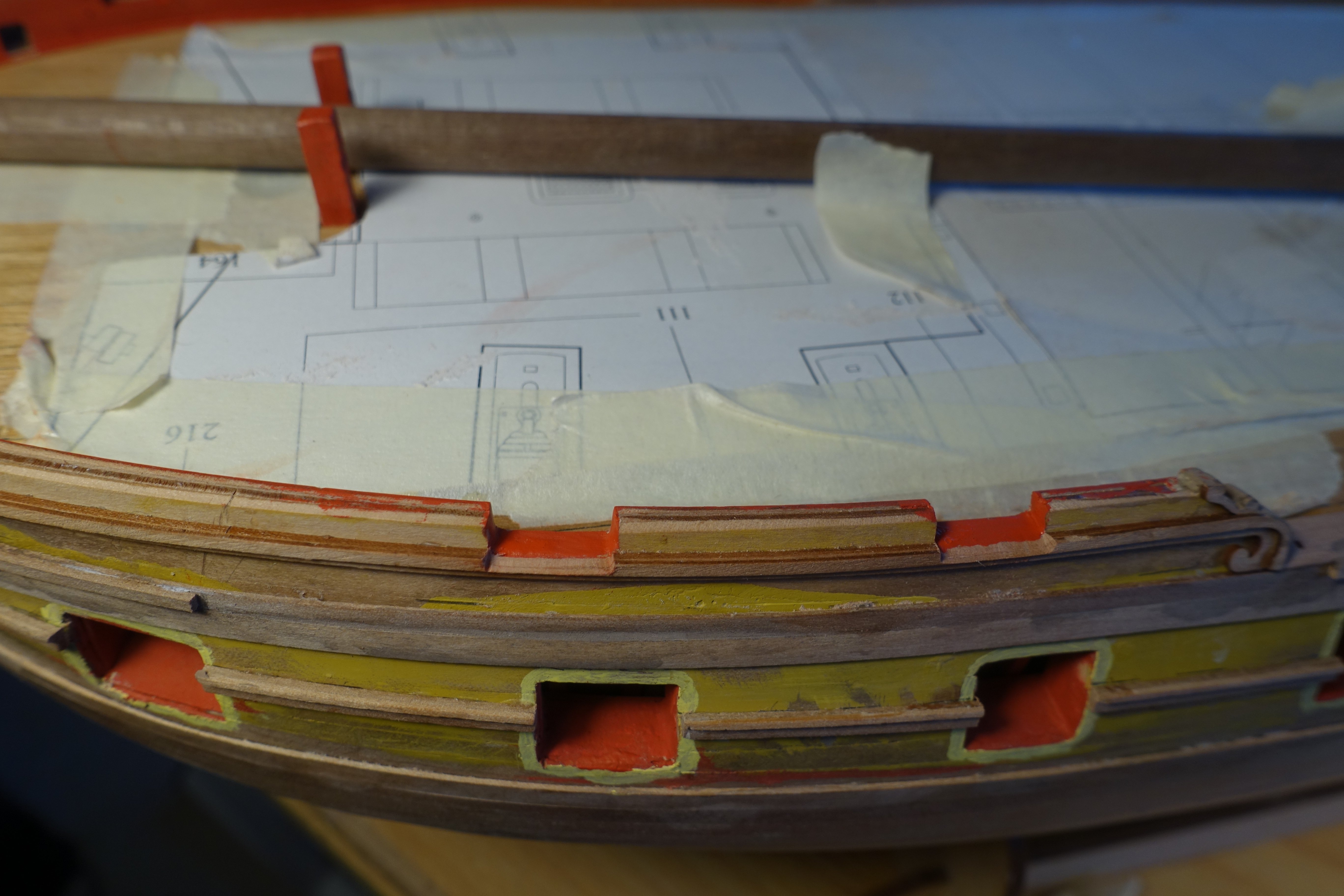
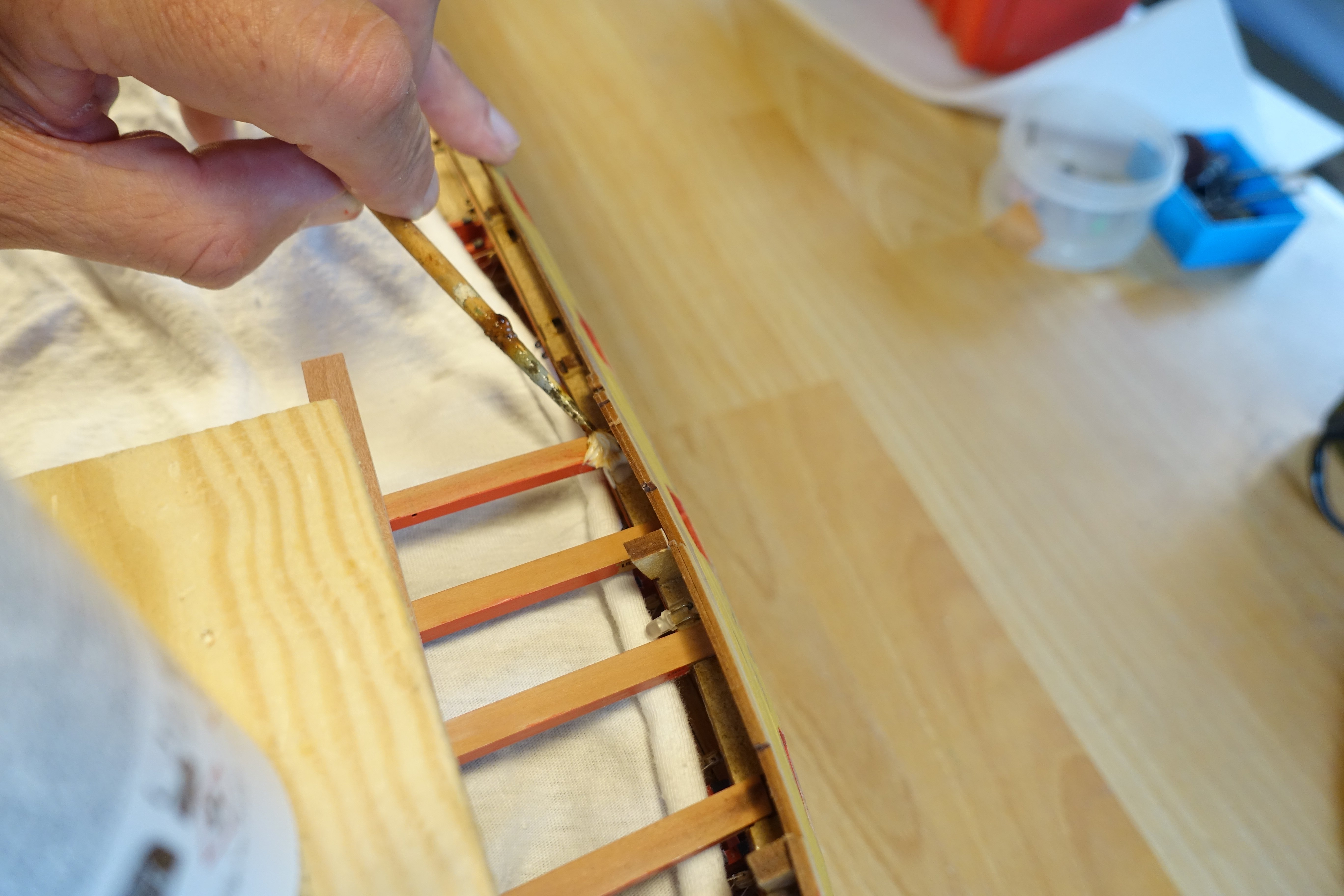
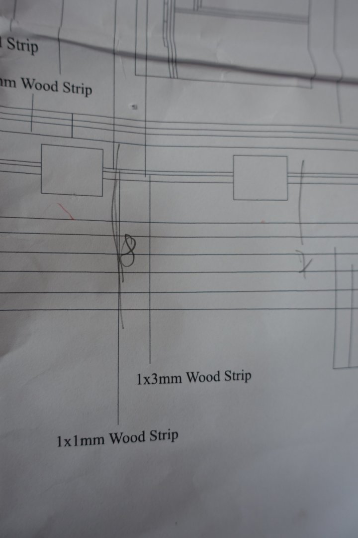
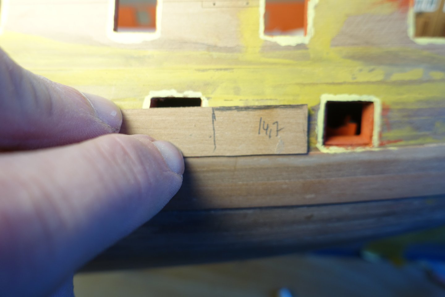
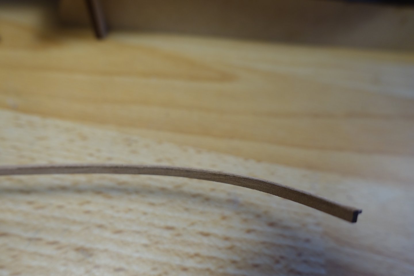
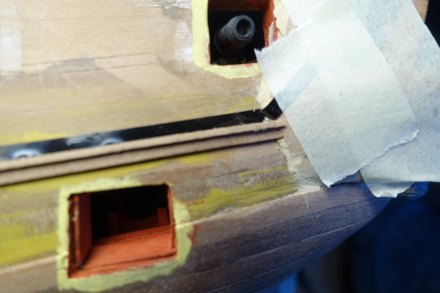
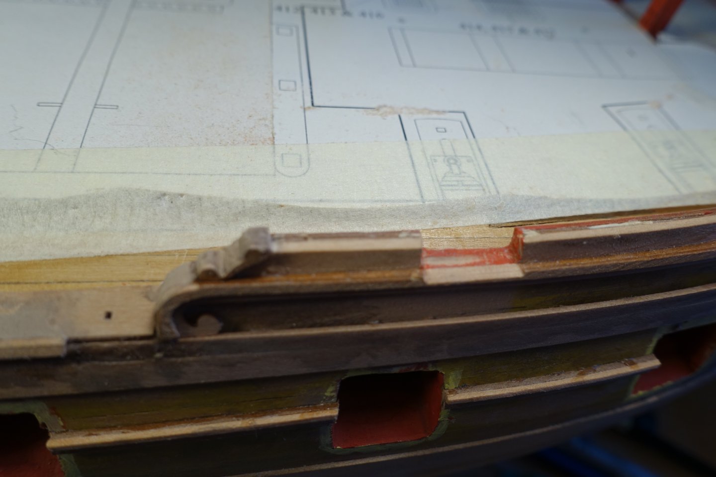
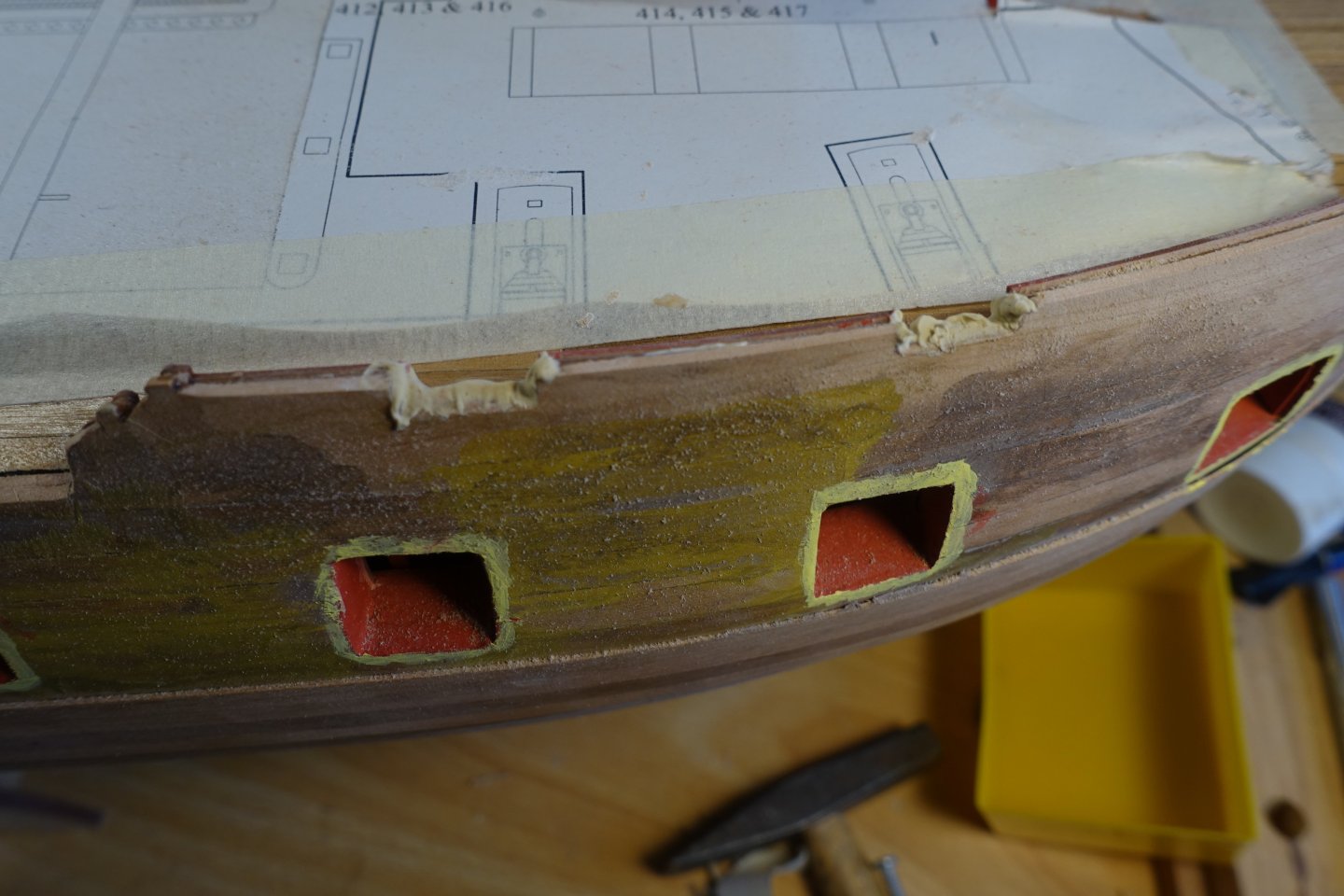
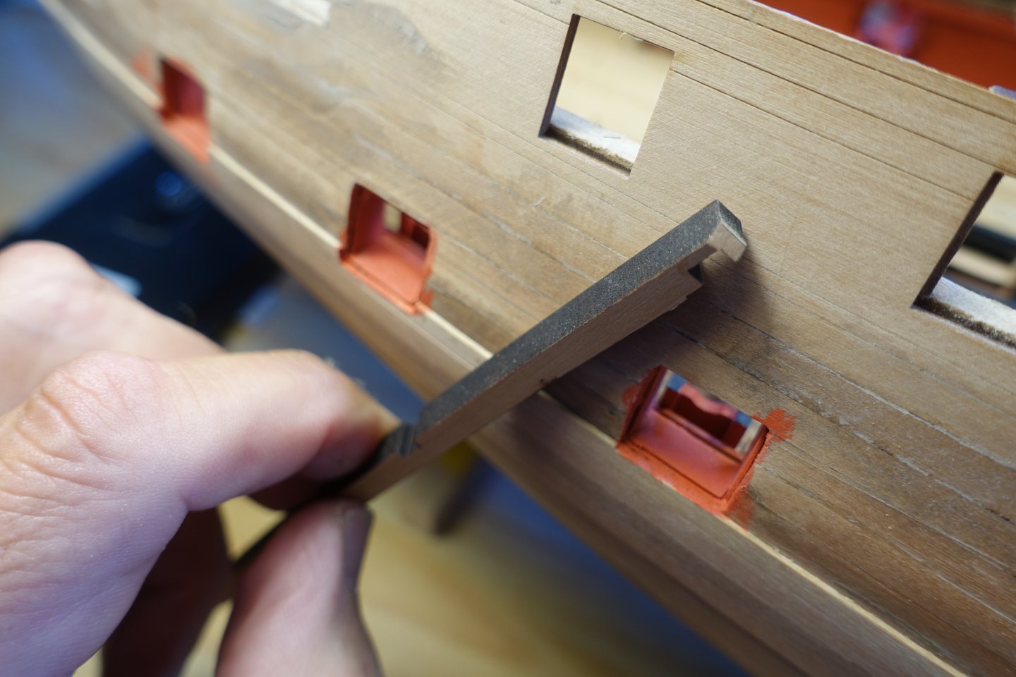
Decorative strips. I started with the strip directly above the wale, which runs partly over the gun ports. At first, I was a little confused because the manual describes that it is composed of a 3x2 mm and a 2x1 mm strip. Logically, these would then have to be bent over the short side. In the plan, this is corrected to 3x1 mm and 1x1 mm, which fits better. To standardise the distance to the wale, I first adjusted a 14.7 mm wide strip and marked the distances. I then glued the two strips together and shaped the bow area with heat. I then divided the entire strip into two parts so that I could adjust it to the bow and stern. I then joined the bow and stern sections together over a gun port. The other strips were attached according to the plans. To glue them in place, I applied small drops of PVA and CA glues alternately at intervals of approx. 10 mm. In order to align the gunwale correctly in the gangway area, I first applied a 2x1 mm thick strip directly to the roll-ups of the decorative strips. The plan shows that both the gunwales and the strip on top are slightly bevelled at the edge, creating a mitre. I wanted to attach the strip without a mitre. It seemed easier to me to fill the small gap with filler afterwards. The gunwales were glued flush with the orientation strip. Then the 3x1 mm strip was glued on. A 4x1 mm strip is glued under the 3x1 mm strip. I didn't do a very neat job in the stern area. A small gap appeared. The gap was filled with filler and sanded down. A 2x1mm strip is then glued onto the upper 3x1mm strip, which runs between the channels. This must be stepped down for a length of approx. 5mm before the gangway area, as it then covers the outer edge of the gunwale of the gangway and is therefore higher in this section. The small gap between the gunwales and this 2x1 strip was filled with filler and sanded down. In the area of the channels, the 2x1 mm strip was attached with an approx. 1 mm overhang. Once the channels are finally attached, it can still be reworked. The decorative strips in the areas of the gun ports were filed down. The gun ports were then painted. As already presented by Blue Ensign, the gap in the bow area was filled with a piece of wood, which was also painted. Otherwise, the cut lines are visible. The part would then have to be integrated into the gunwales later. All in all, attaching the decorative strips was a little more complicated than I had first thought. Next, the gunwales will be attached.


-
Thanks and also thanks for stopping by. Clark
-
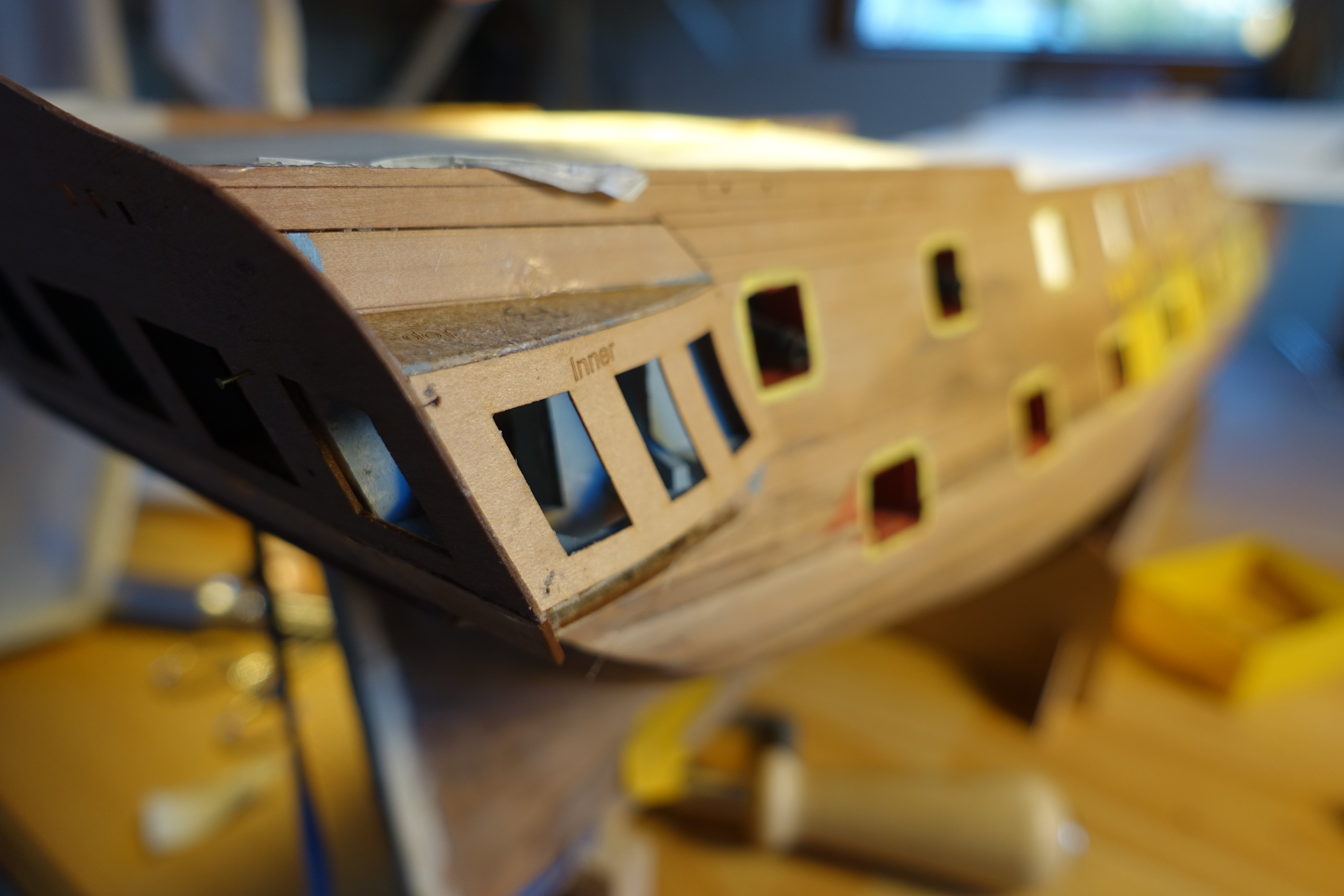
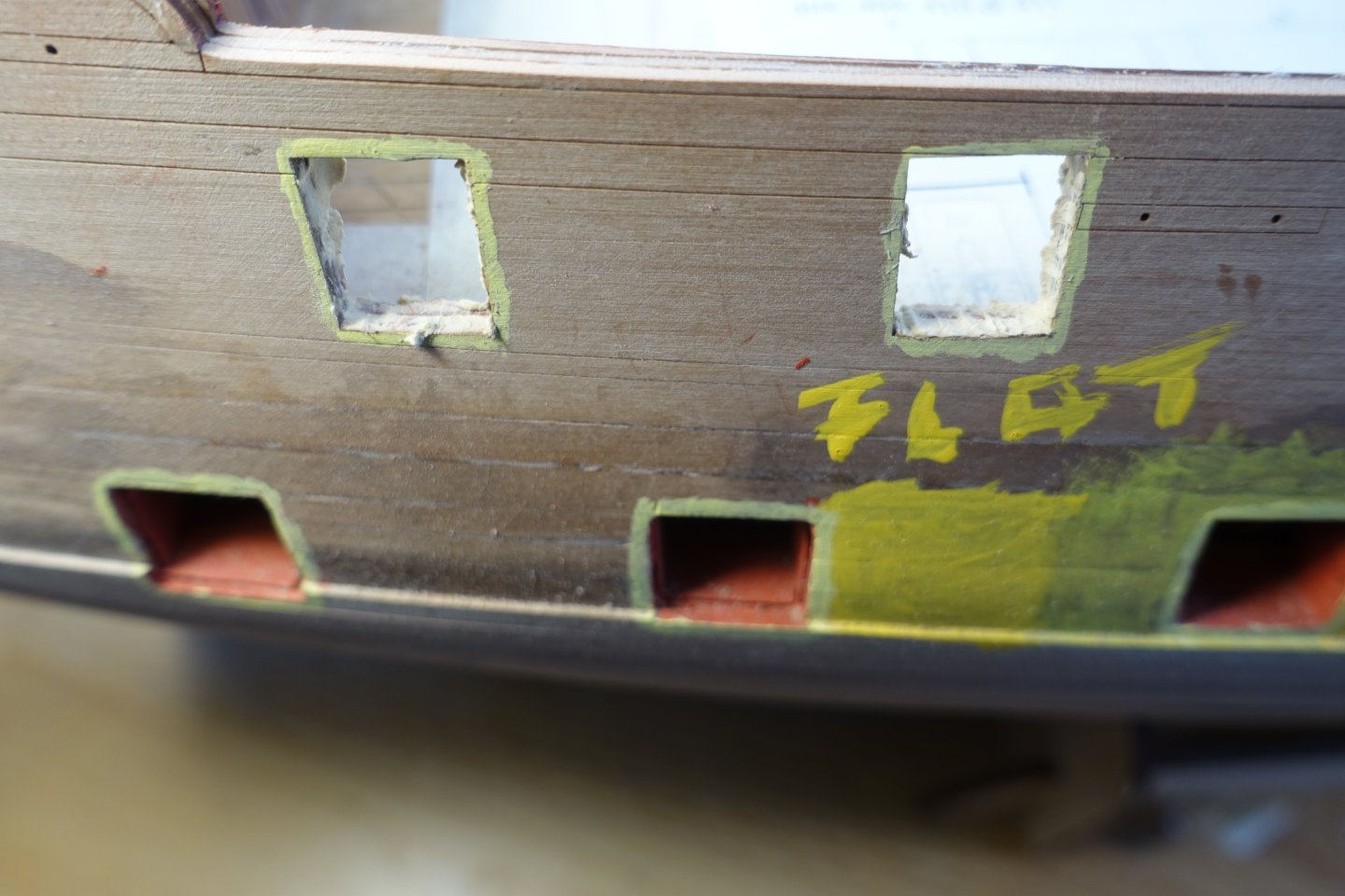
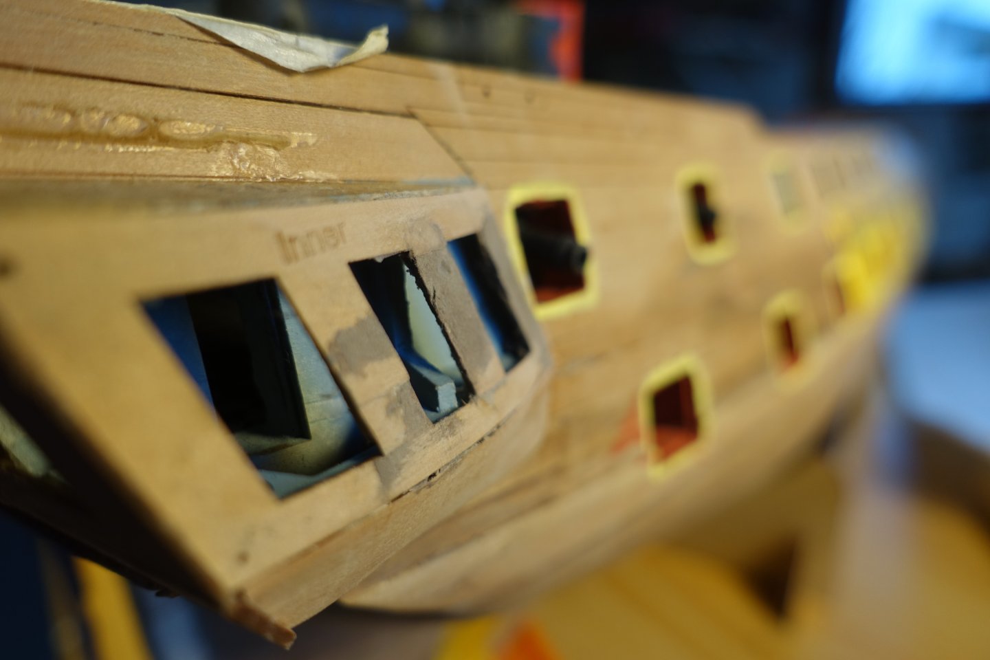
Brief update. Inner bulwark. The patterns for the inner bulwark were relatively easy to fit. The gun ports were lightly filled. 6305 Openings were sanded . After painting the gun ports, it became apparent that there was a gap between bulwark at the port side and the deck in the bow area. 6312 The gap was covered with a 1 mm x 1 mm strip. Subsequently, a strip was also added to the starboard side and the quarterdeck. Next, the outer decorative strips will be attached.

-
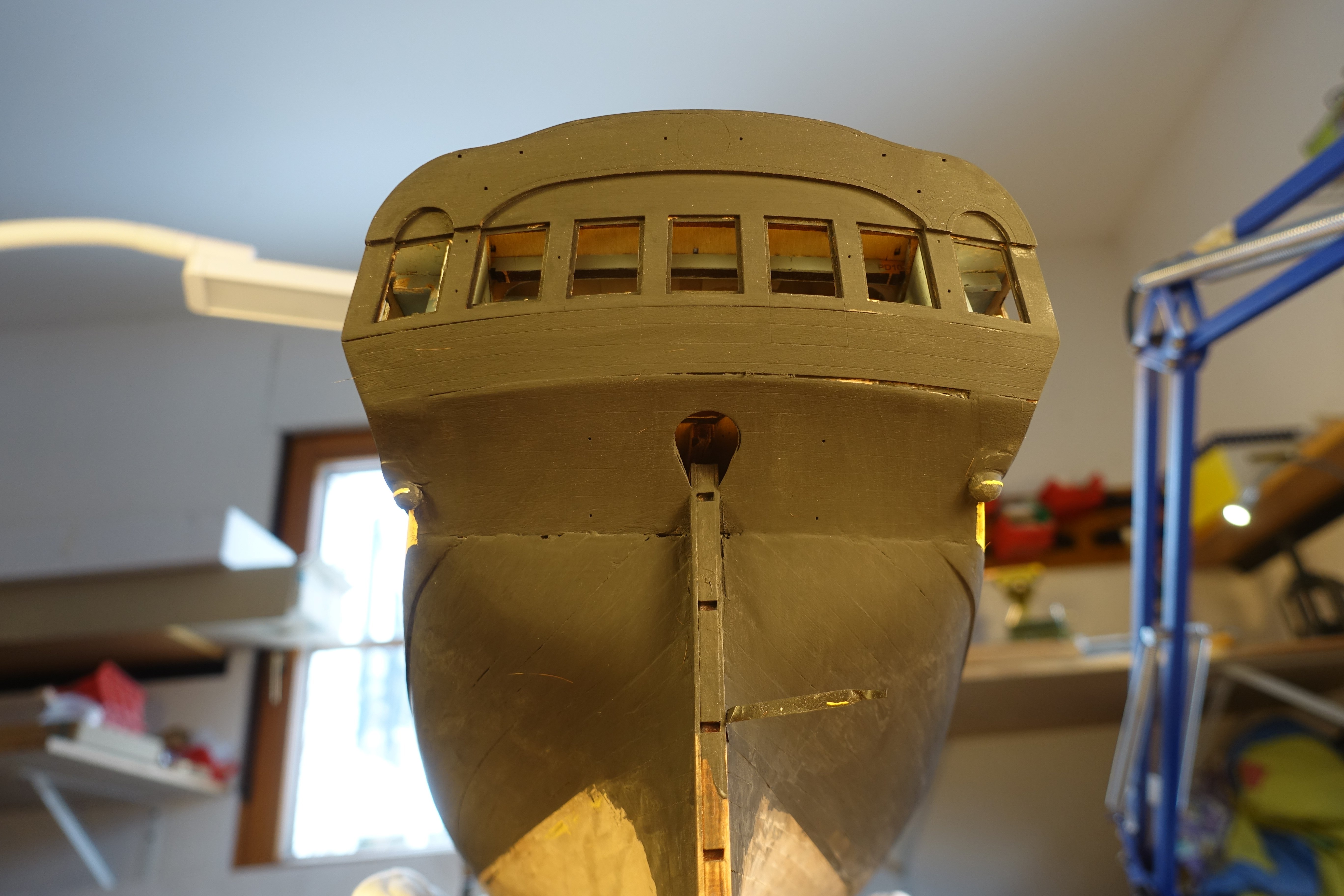
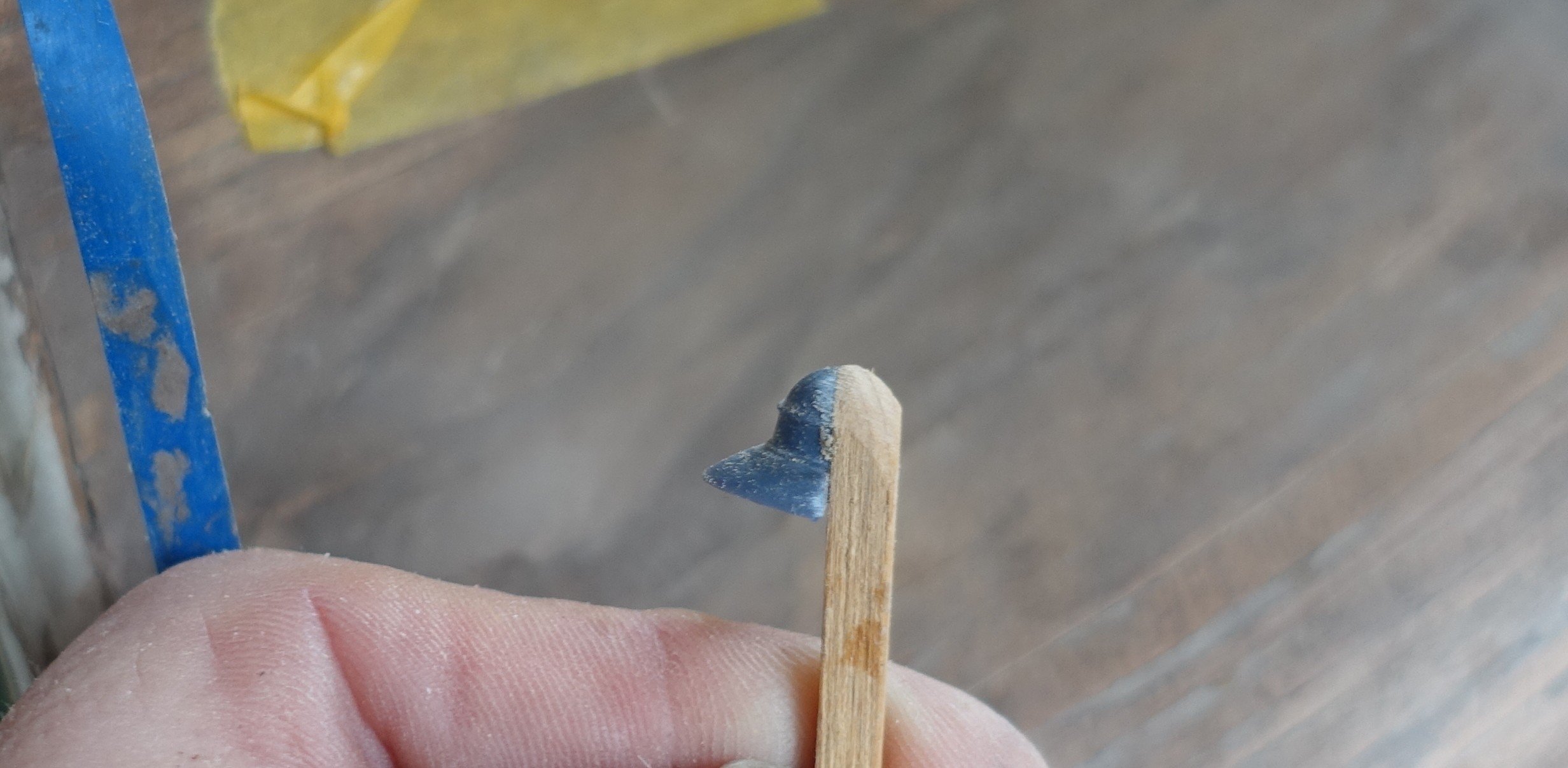
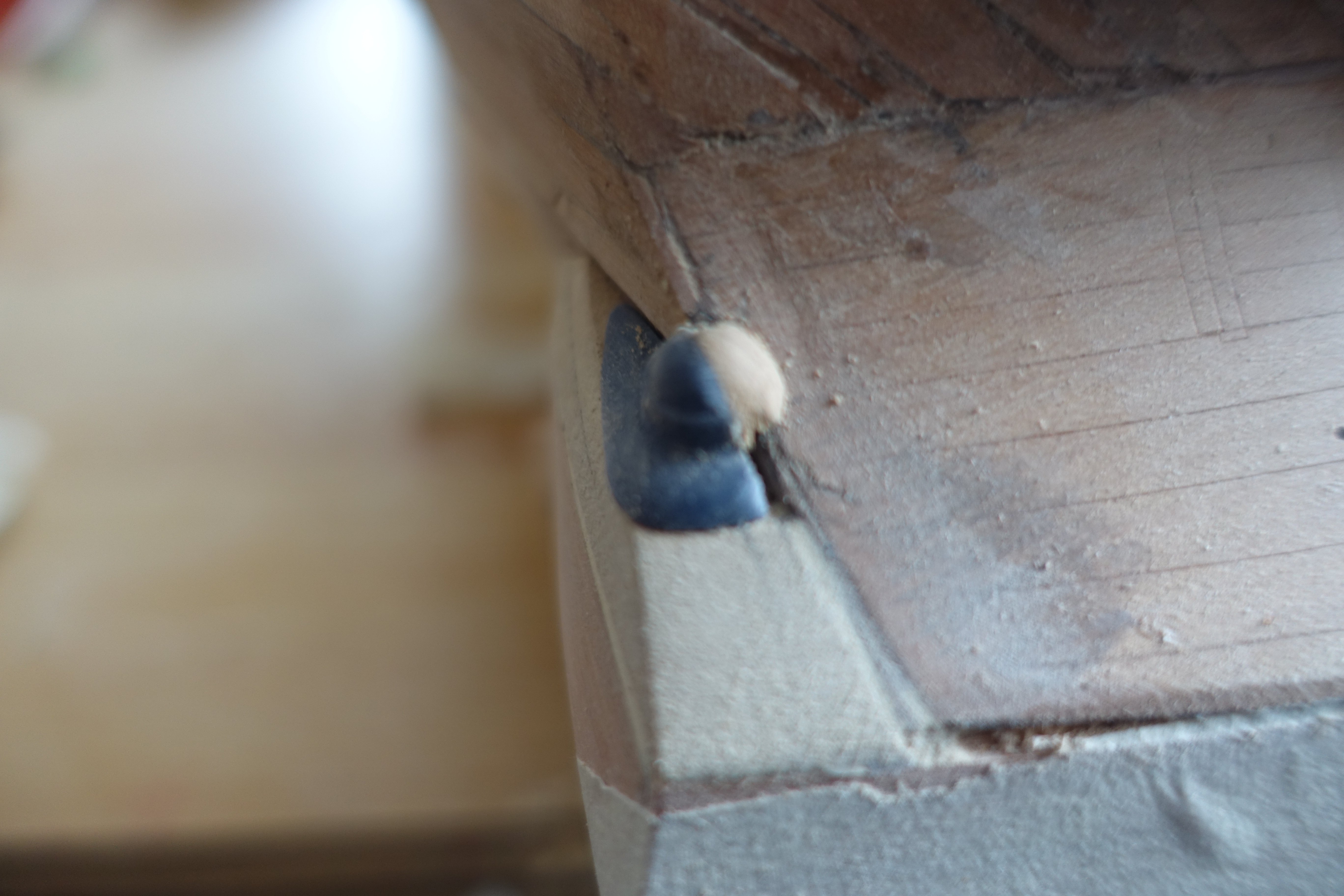
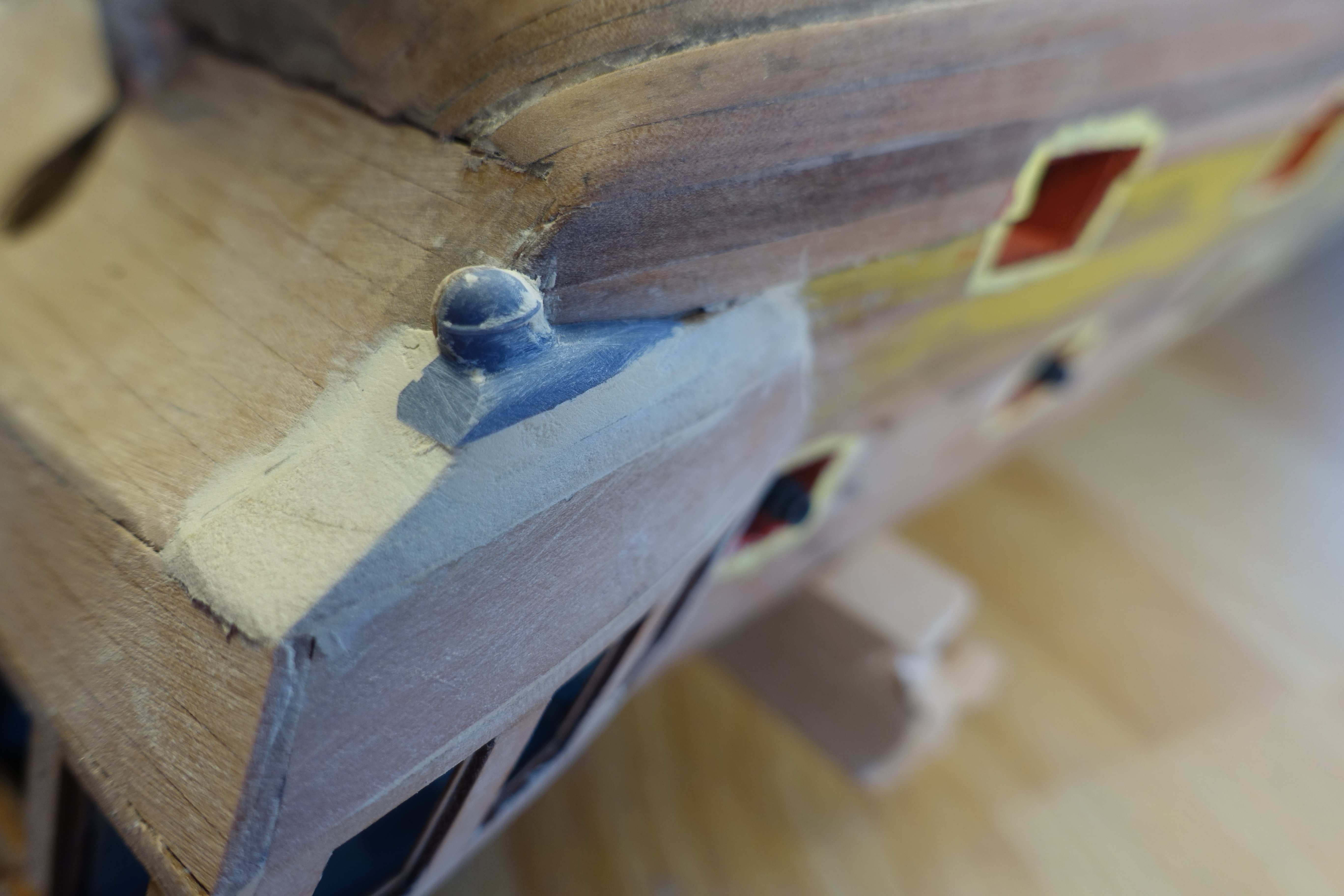
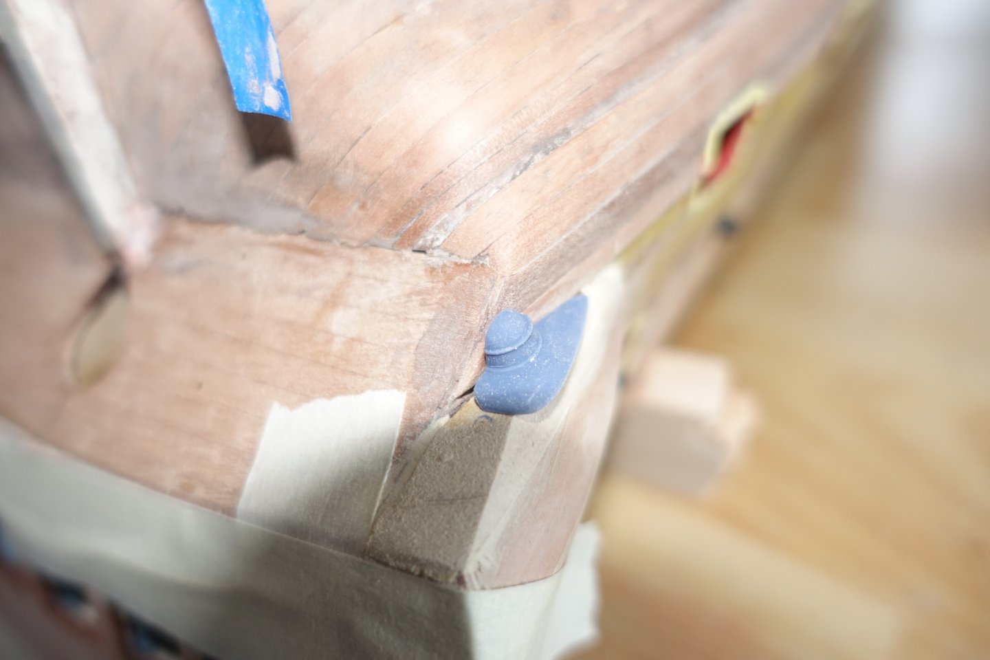
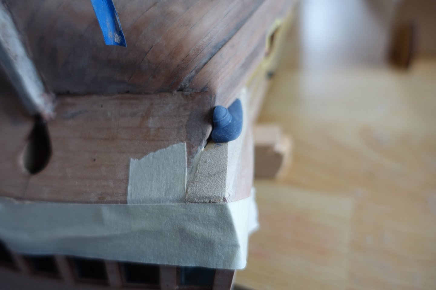
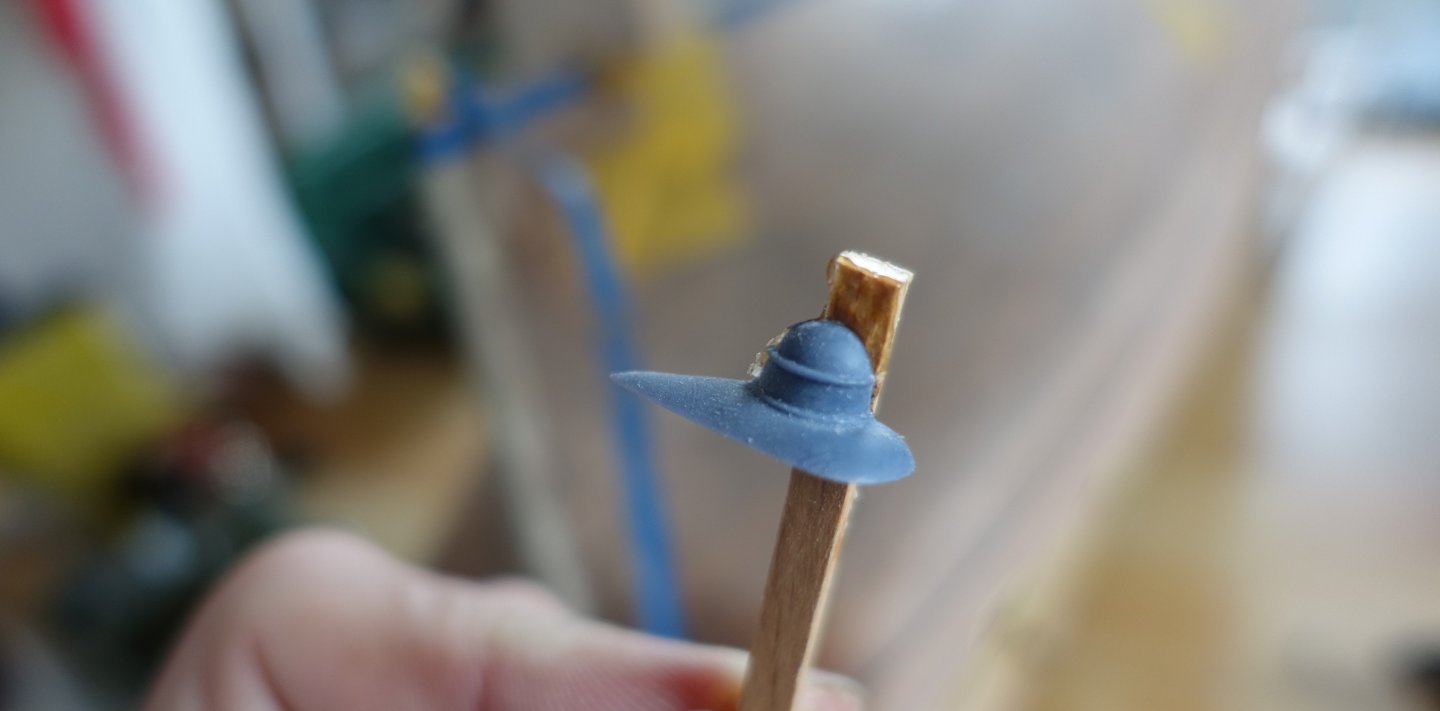
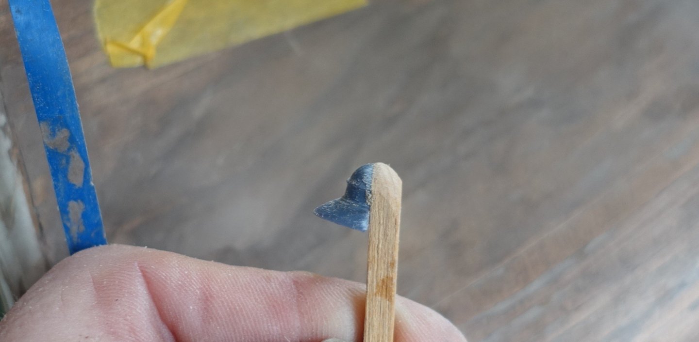
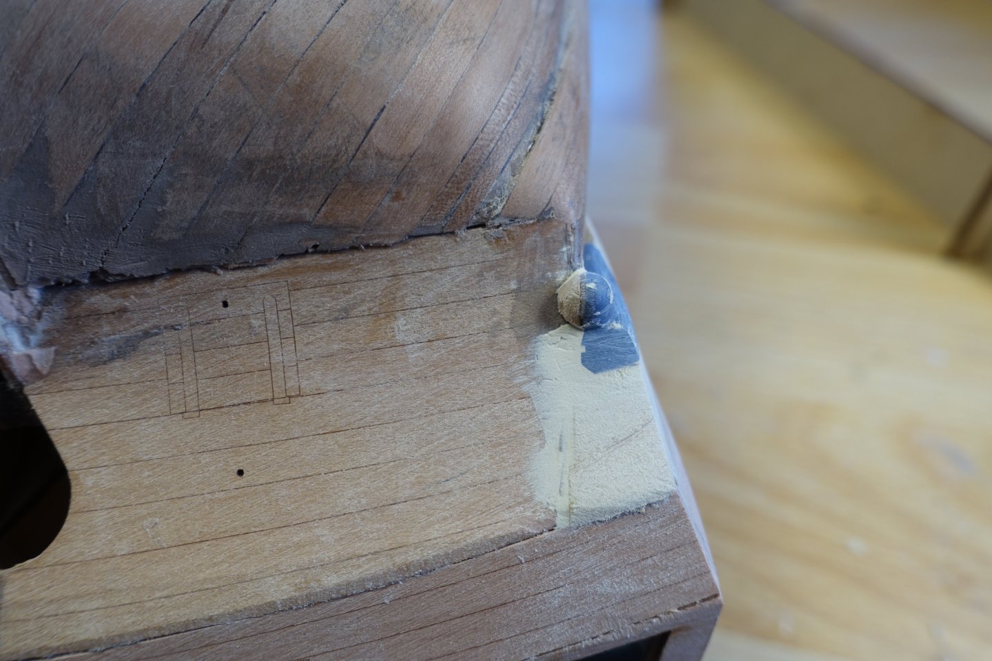
Gallery As already described in the other blogs, the gallery is not that easy. I had my first surprise after installing the inner panel. The window supports were bent, perhaps because I had wiped off the excess glue with a damp brush. The wood is very sensitive to moisture. The indentation was levelled out with filler. The outer panel was slightly bent with heat. However, I had problems making the transition from the outer panel to the hull smooth. At least in my build, the panel was too short to be sufficiently bevelled. Here, too, I used filler to create the transition. As suggested by Blue Ensign, I bent the lower panels also slightly with heat. A simple hairdryer was sufficient. The kit includes resin drops. However, if you adjust these according to the plans, they protrude quite a bit. These need to be set back to fit reasonably well. The kit also includes MDF drop moulds. However, I wasn't entirely happy with these either. I therefore decided to set the drops back, which meant that they protruded above the counter. To continue the protrusion, I first glued the MDF drops to the resin drops. However, when I continued sanding, the MDF-drops fell apart, so I glued on a 4x4mm wood strip. This was then sanded down further. After cutting to size, the drop was glued on. The gap is caused by the drop meeting the wale in the upper section. The gaps were filled with filler. Next, I will adjust the inner bulwarks. I think this is a little less complicated than the gallery.


-
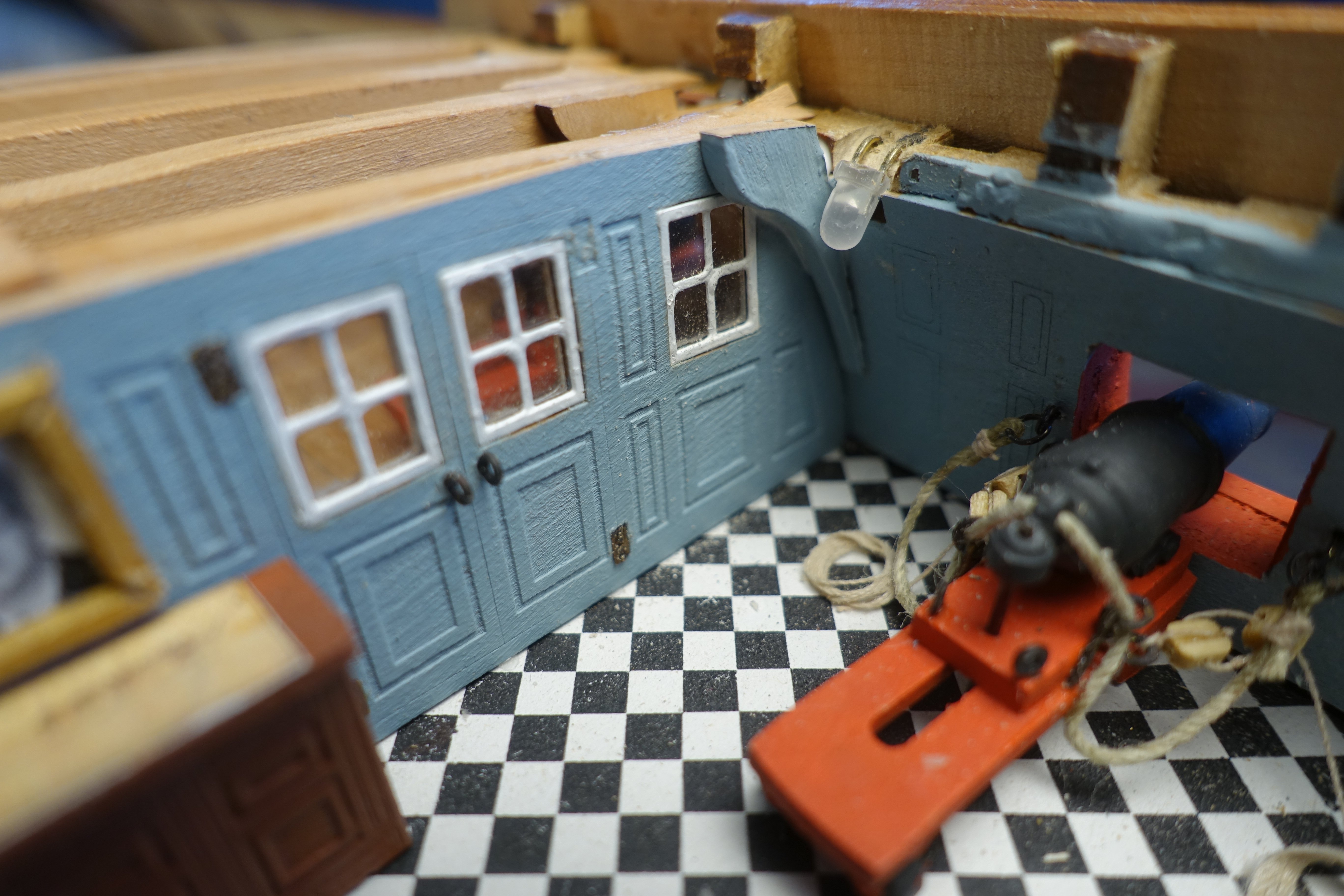
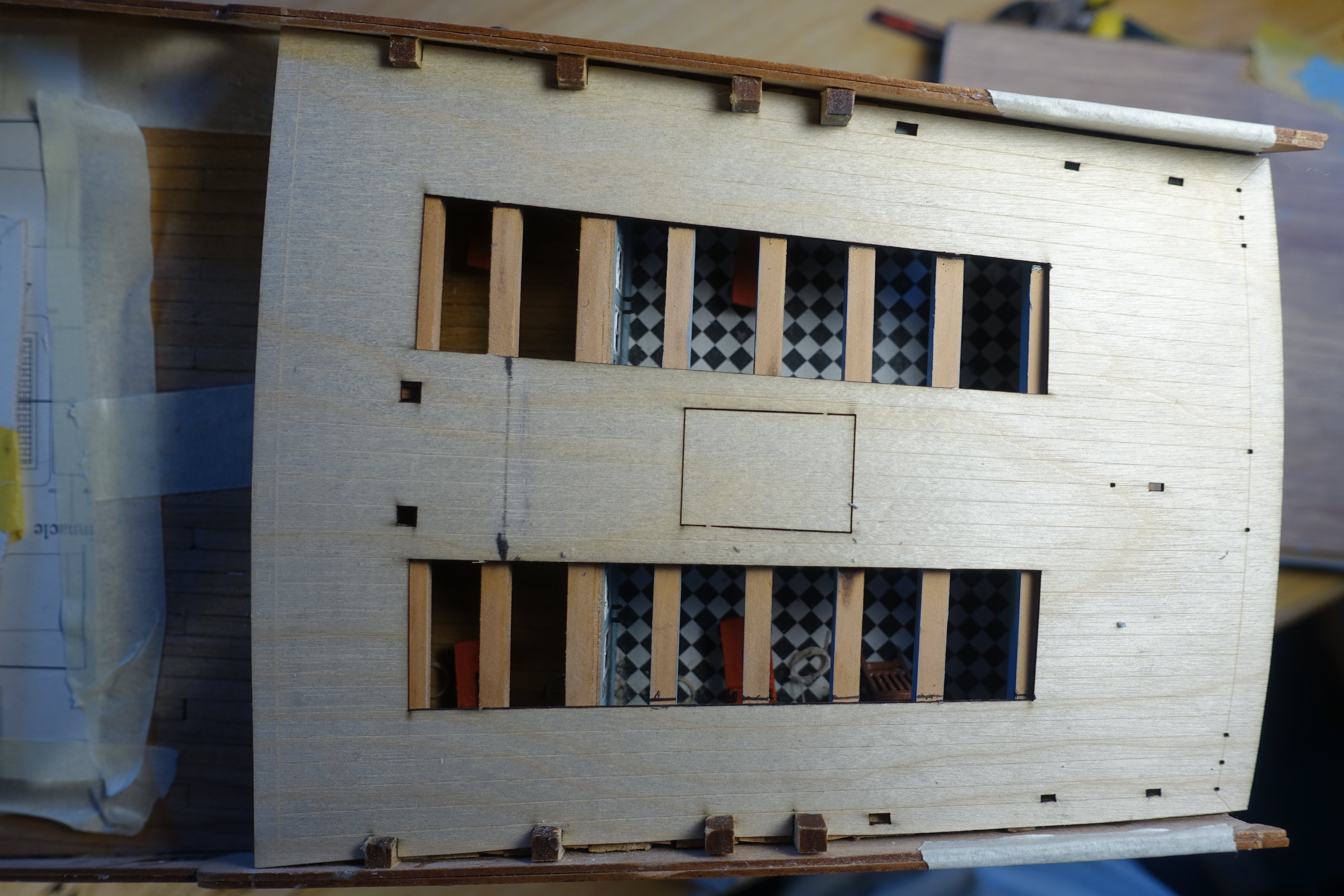
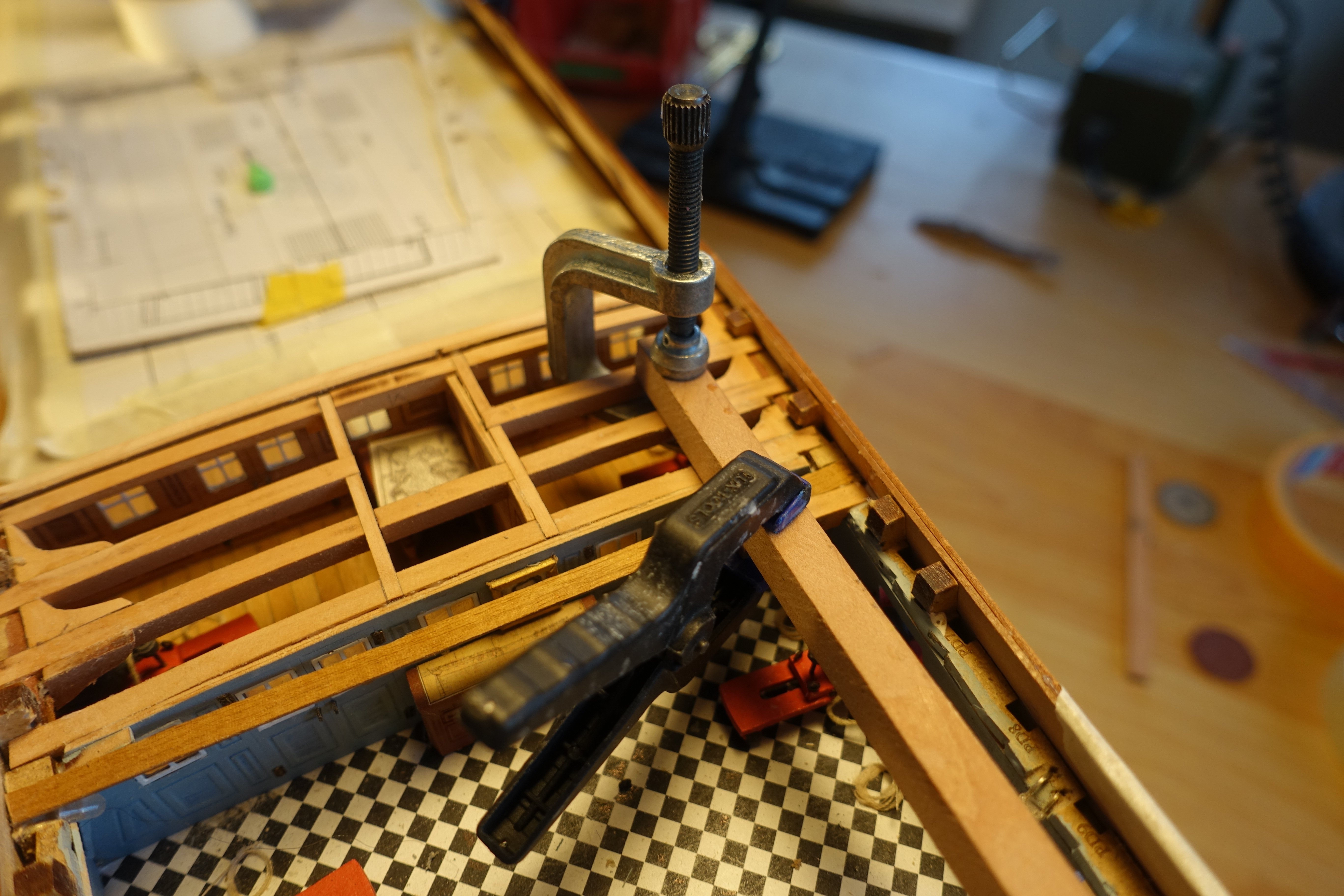
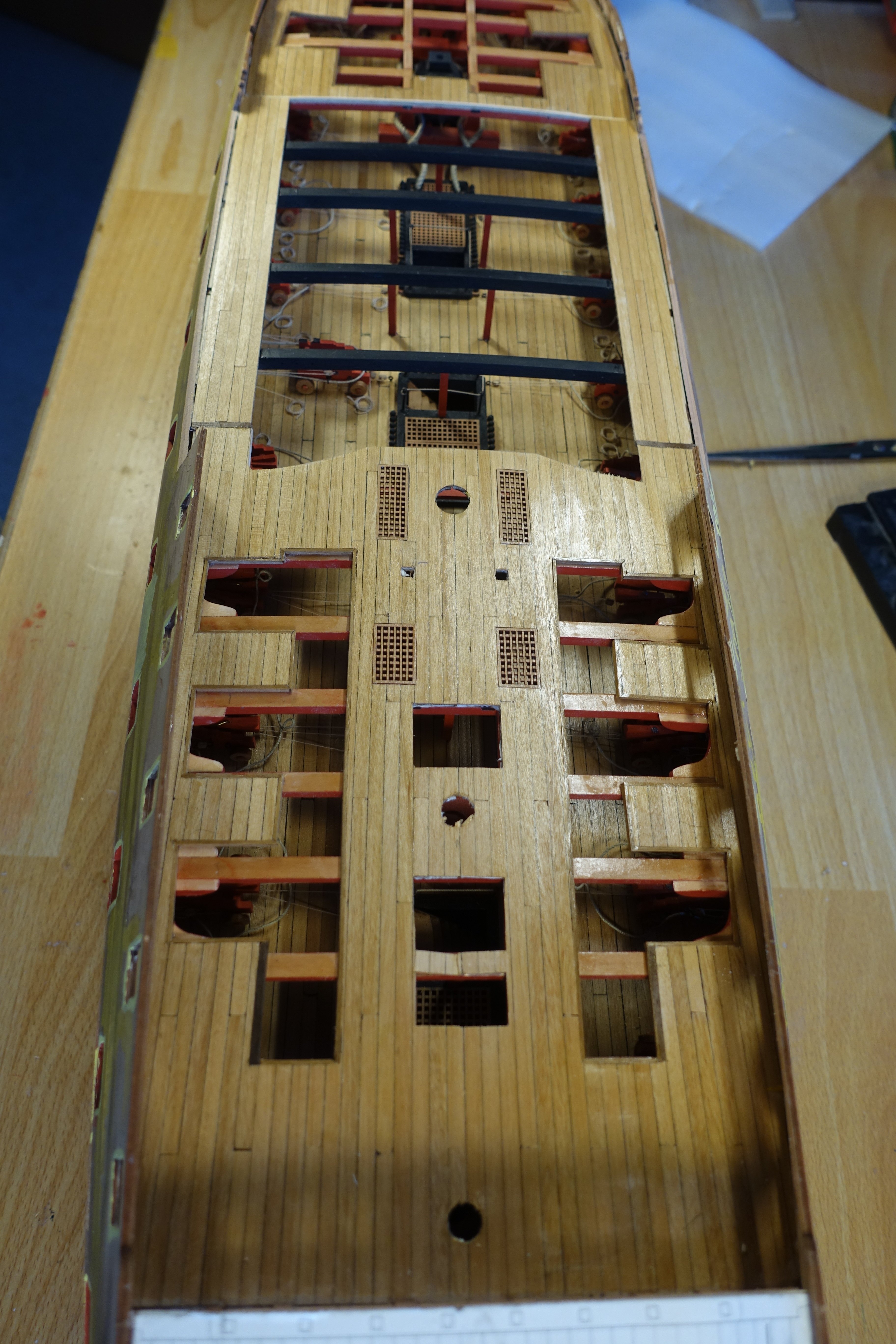
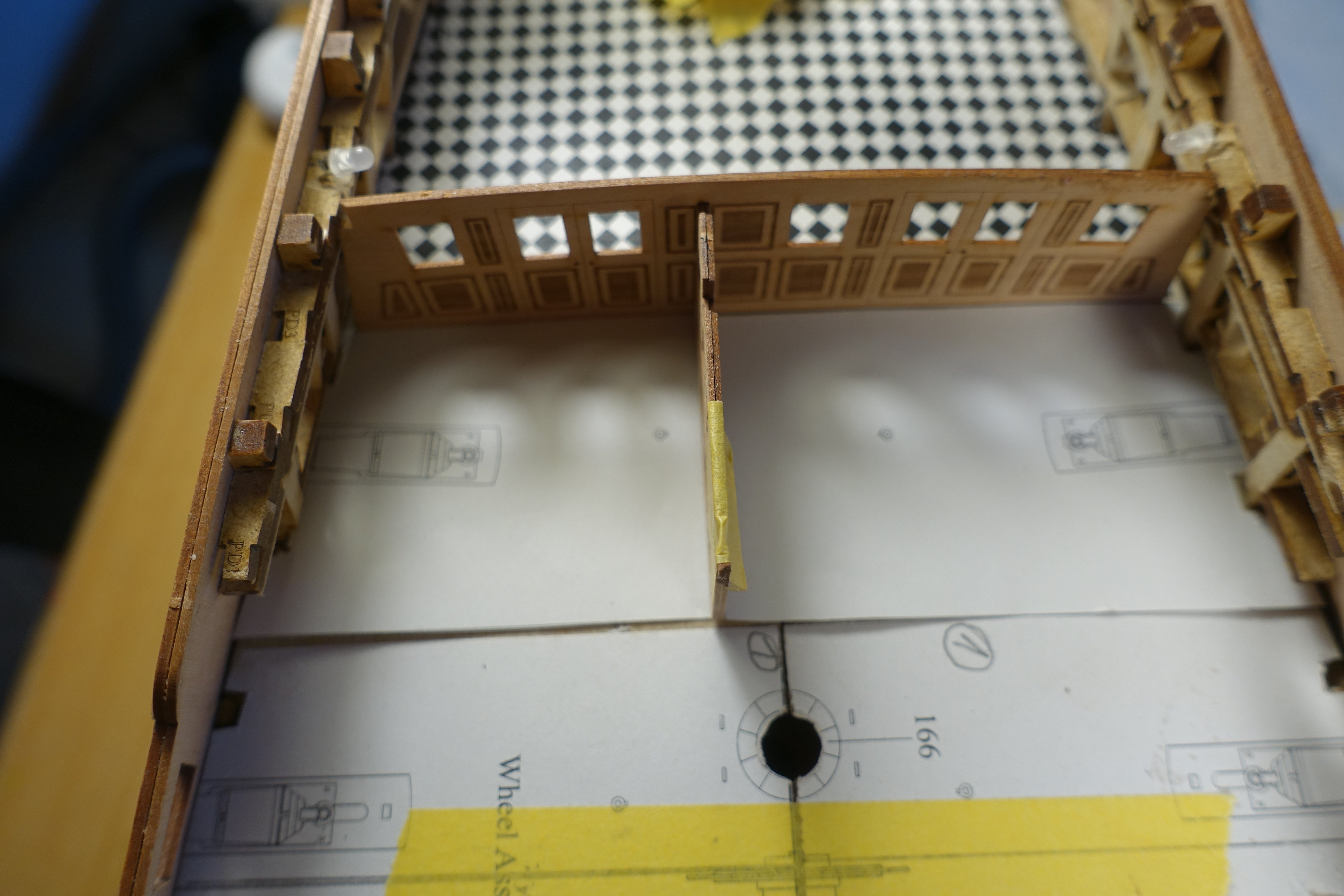
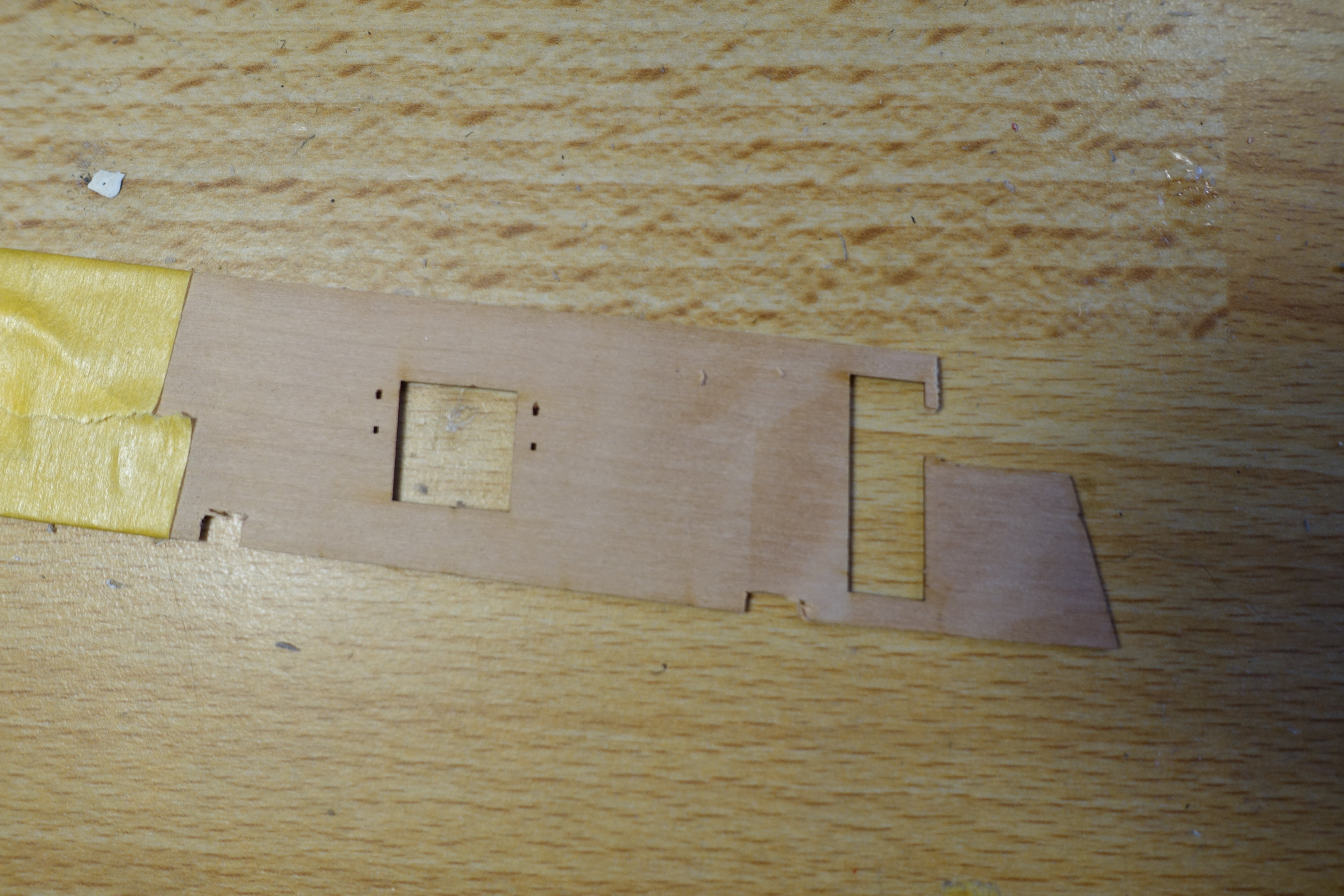
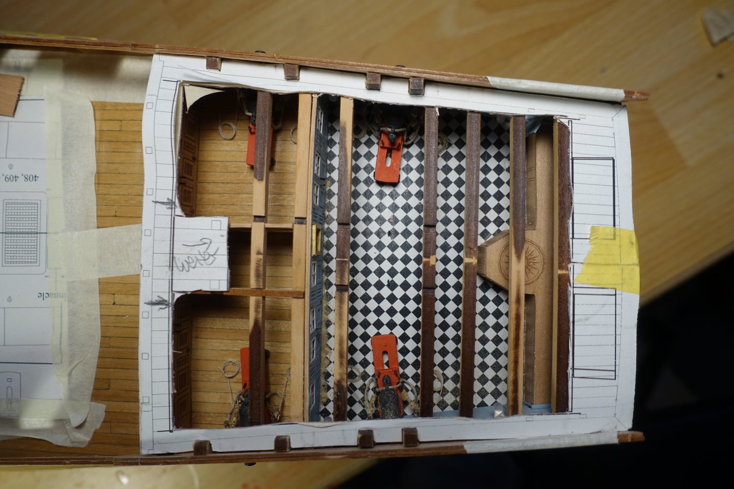
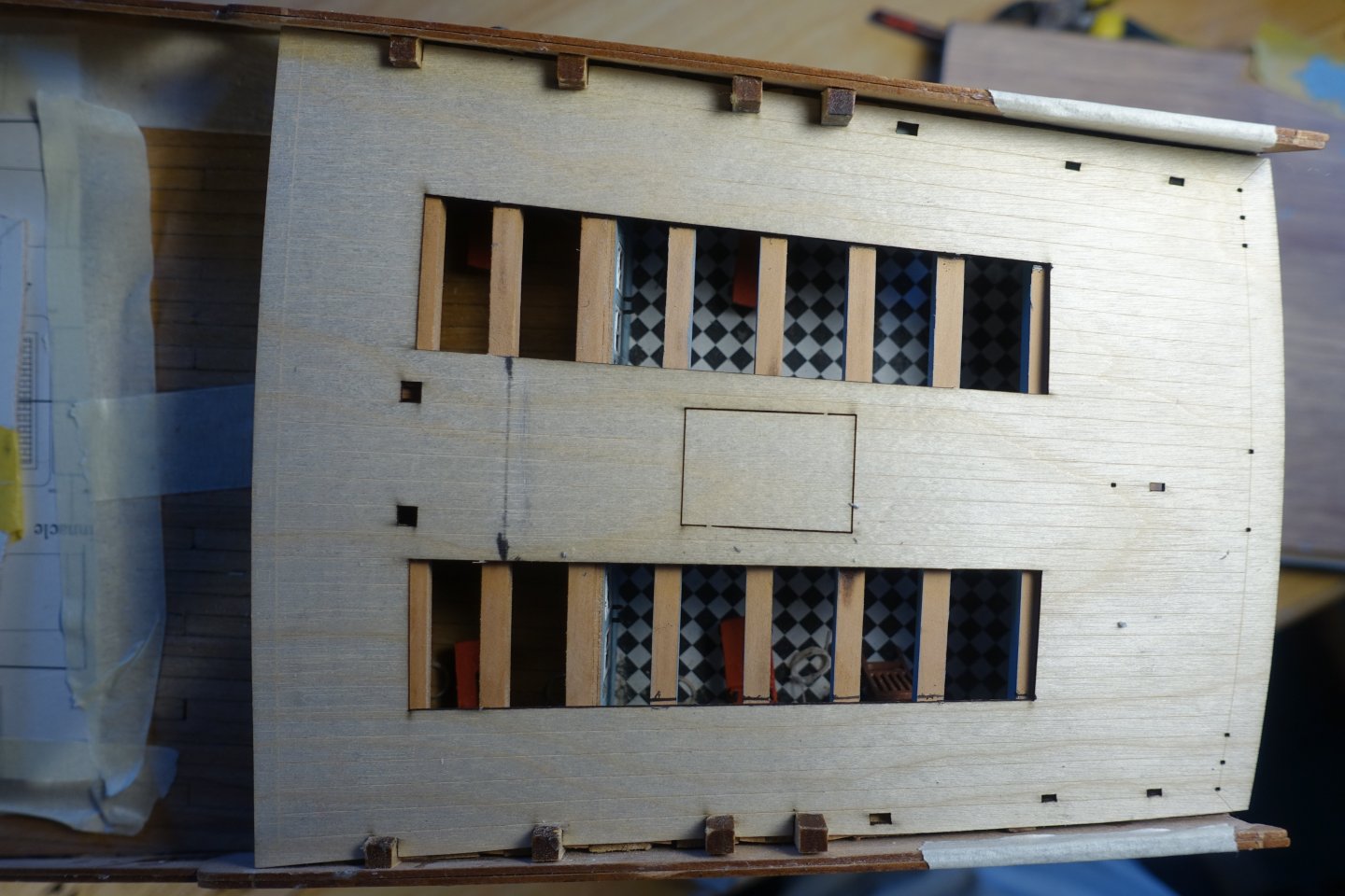
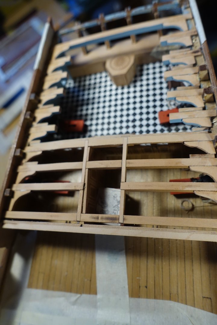
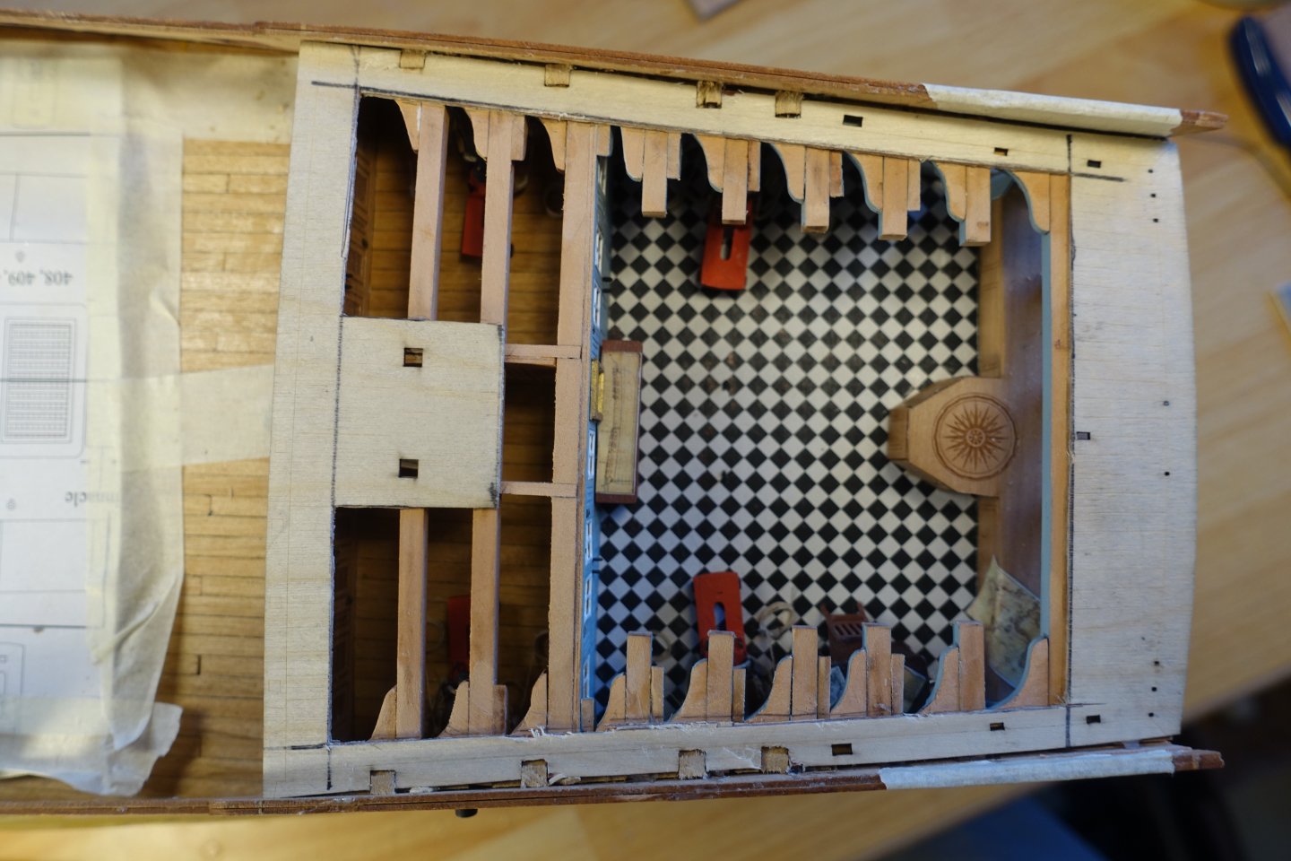
Poop Deck I wanted to make the poop deck as open as possible and also shorten the deck beams to ensure a clear view into the captain's cabin. First, I designed a template for the deck and put it on the untreated deck beams: The knees were prepared, whereby the knee on the bulkhead had to be reduced in size to ensure an unobstructed view of the windows. A door hinge came loose and will be replaced later. The untreated subdeck was fitted. The existing cut-outs were used to mark the shortening of the deck beams (see pencil marks). To position the shortened deck beams, a 10x10mm piece of wood was placed over the intact deck beams and locked in place. The deck beams were shortened at the markings and glued in place with the help of the 10x10 mm piece of wood. The knees were then attached. The subdeck was cut to size and attached. The subdeck was planked and, as with the other decks, the cut-out was bordered with 1x2 mm strips. The cabin will later be furnished with additional furniture, accessories and people.


-
Hope the impression will even be enhanced by the LED.
-
Thanks for the compliments und also Thanks for stopping by. Clark
-
Thank you very much. I am currently adjusting the cut-outs for the poop deck. This should be almost completely open.
-
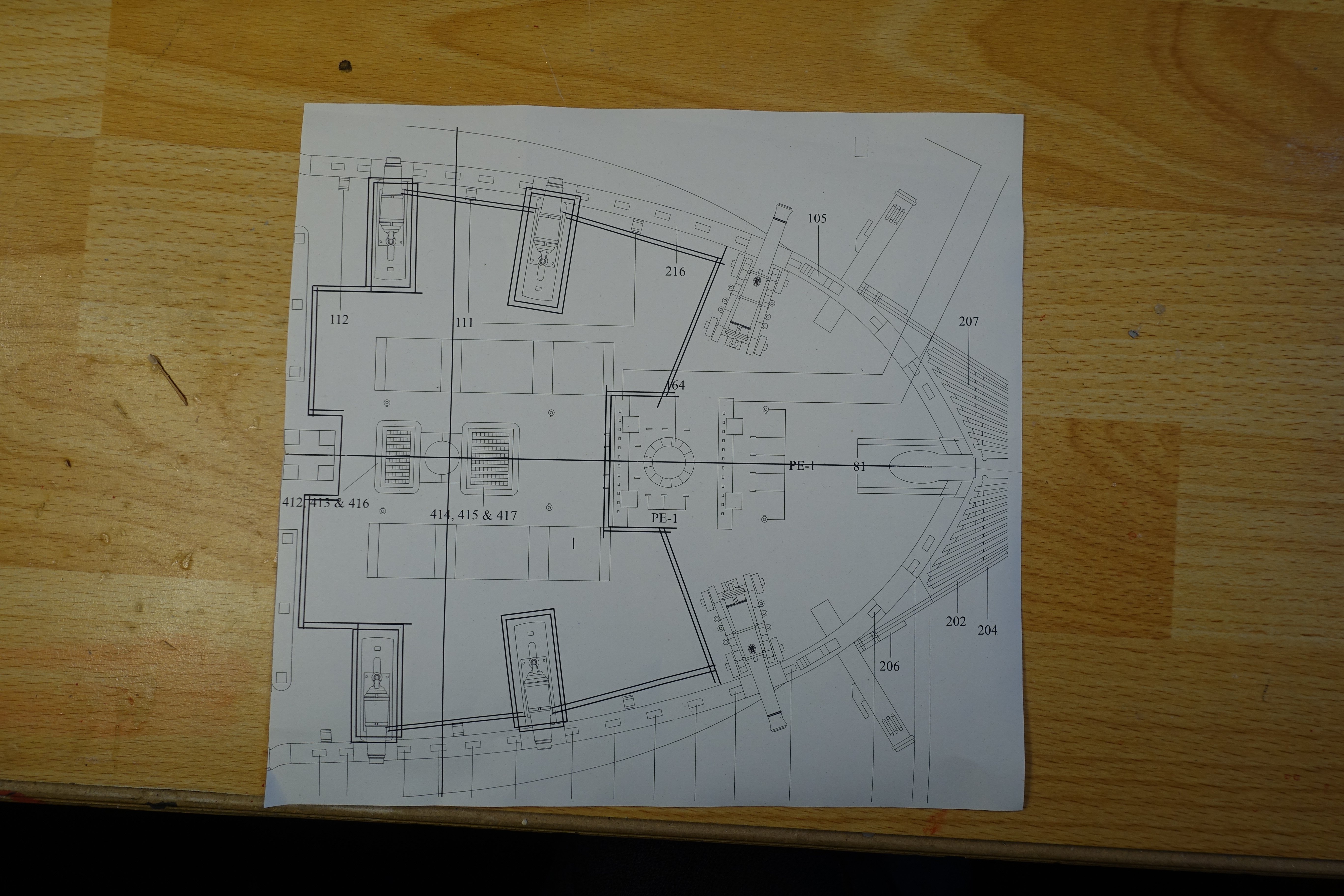
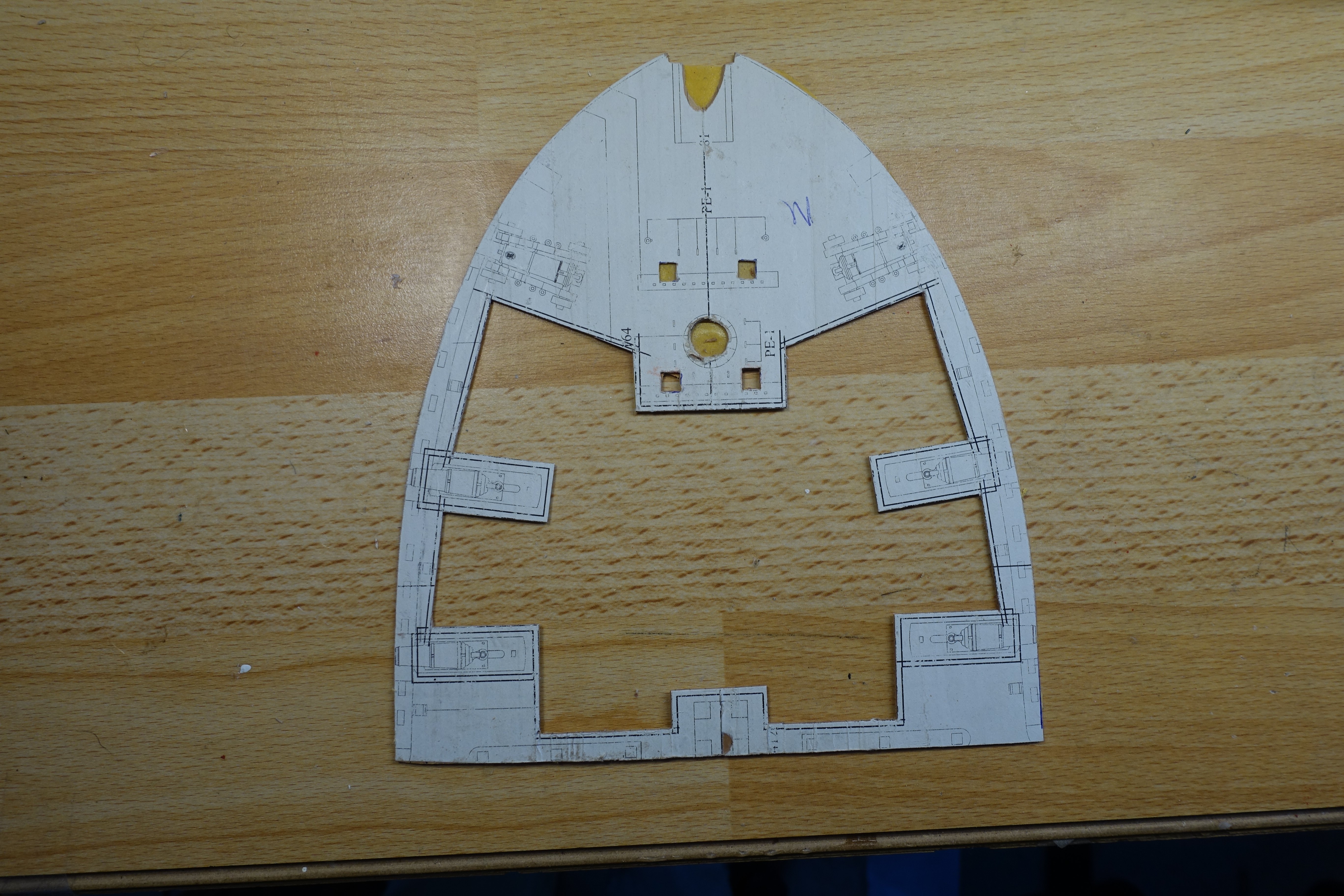
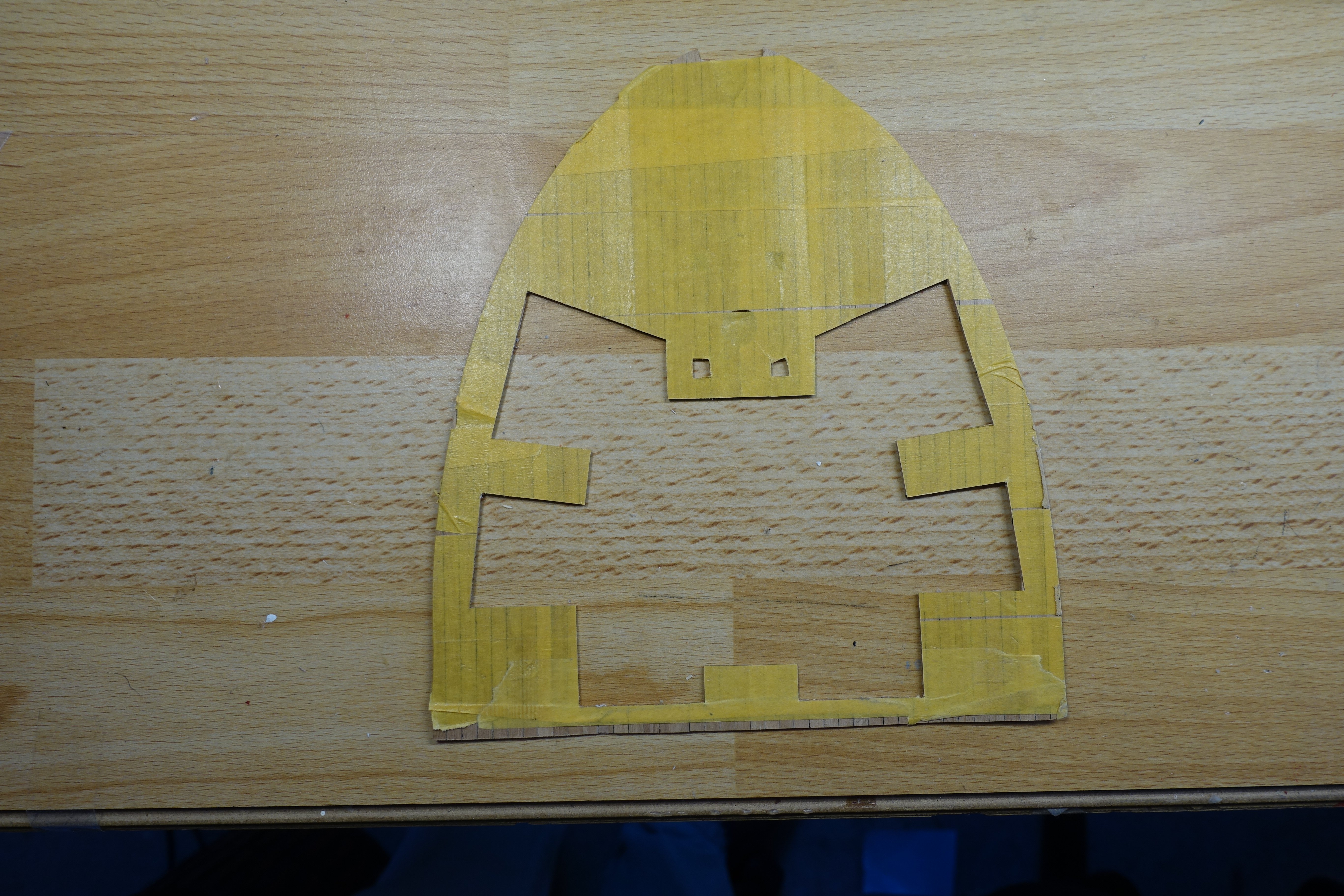
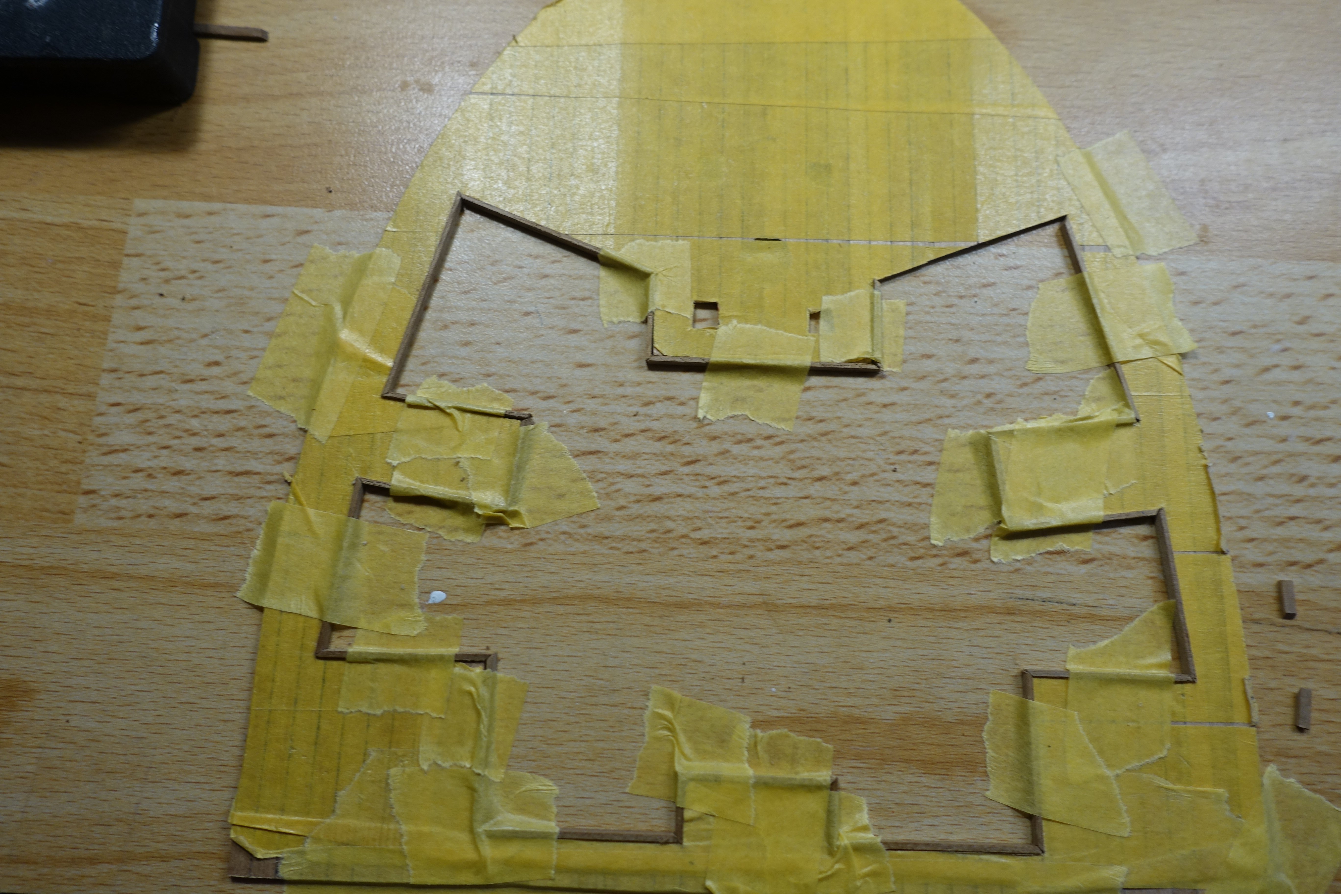
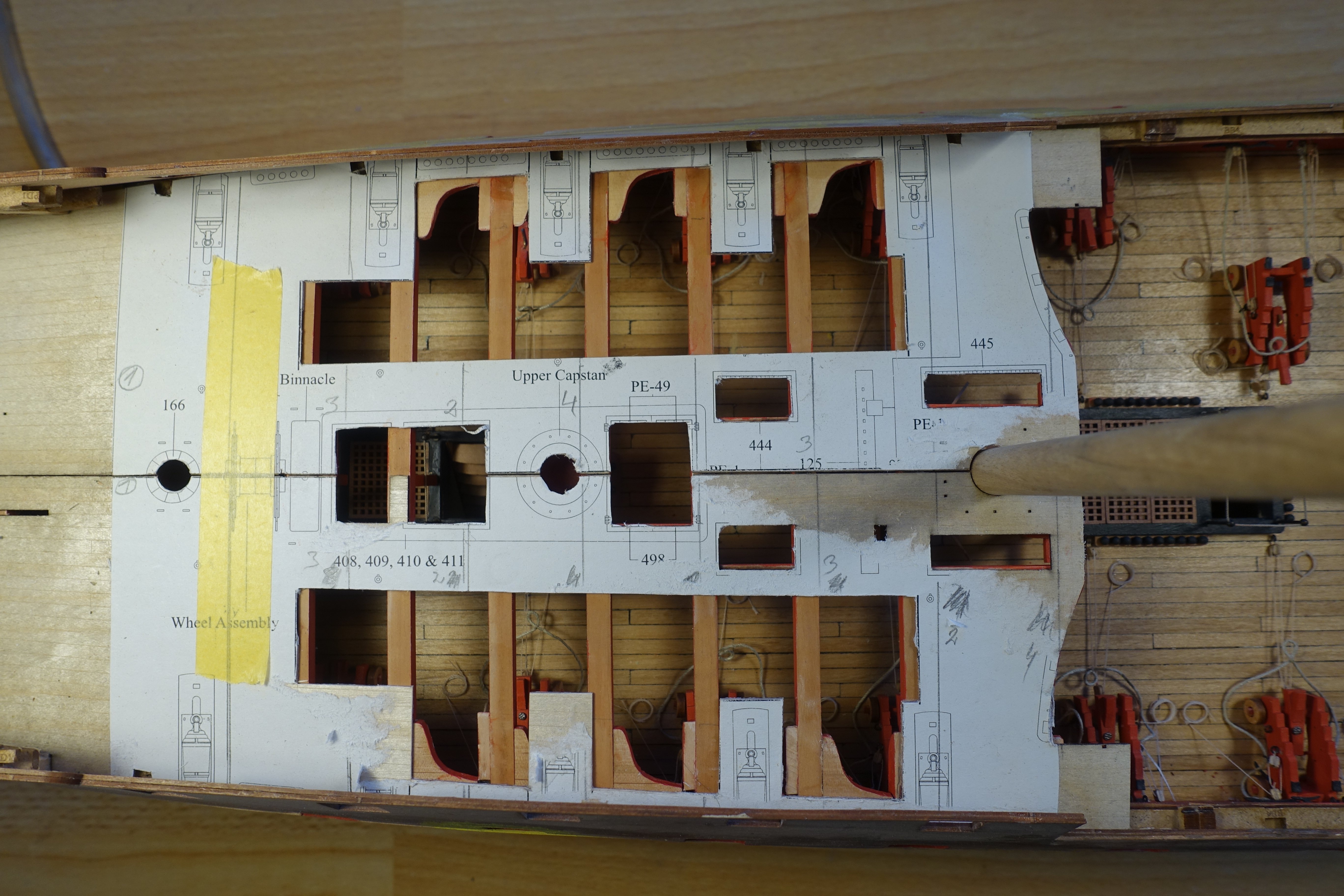
Planking of forecastle, gangway and aft deck. For the forecastle, I transferred the cut-outs onto paper again, indenting the lines by 1 mm compared to those for the subdeck. After the planks had been glued on, they were cut or punched out along the specified lines. The cut-outs were to be masked later with a 1x2 mm strip. The length and mitre of the strips were adjusted outside the ship. The deck was fitted and the prefabricated boundary strips were glued in place. The procedure for the aft deck was the same as for the forecastle. I wanted to fit the gangway now and glue the knees in place first. However, one of the knees conflicts with a cleat. In the end, I decided not to glue any knees in place. The planking of the three sections is now complete.


-
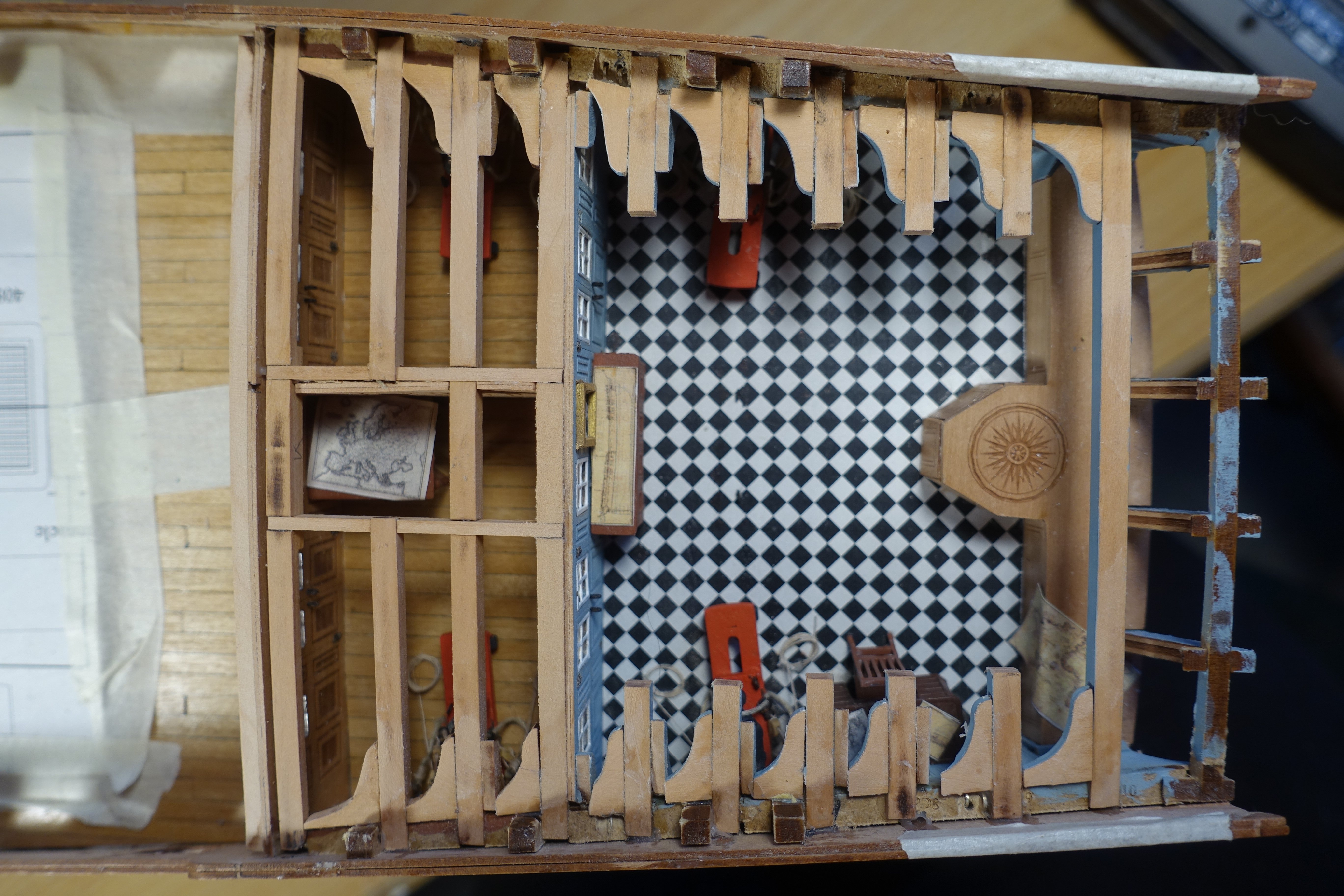
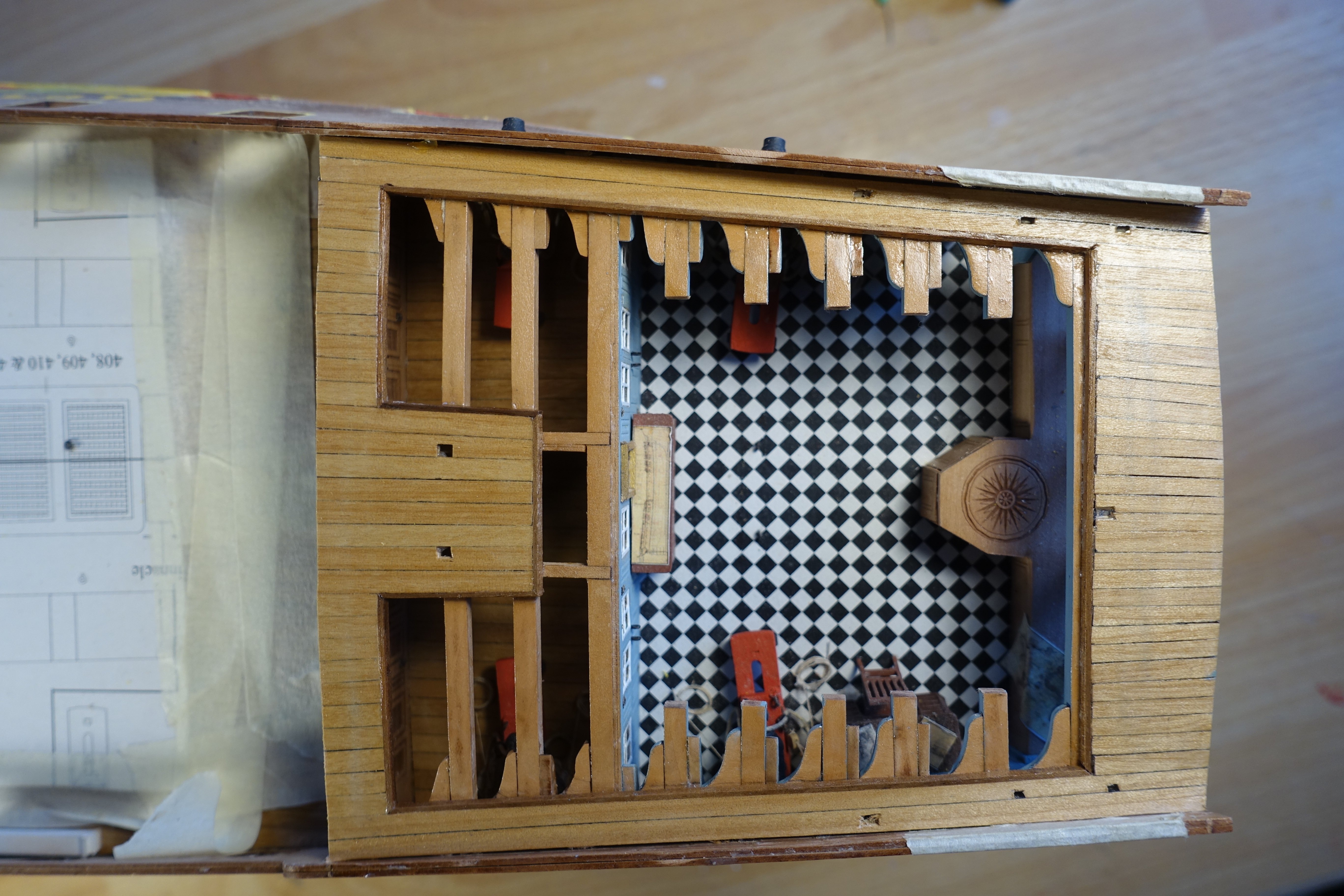
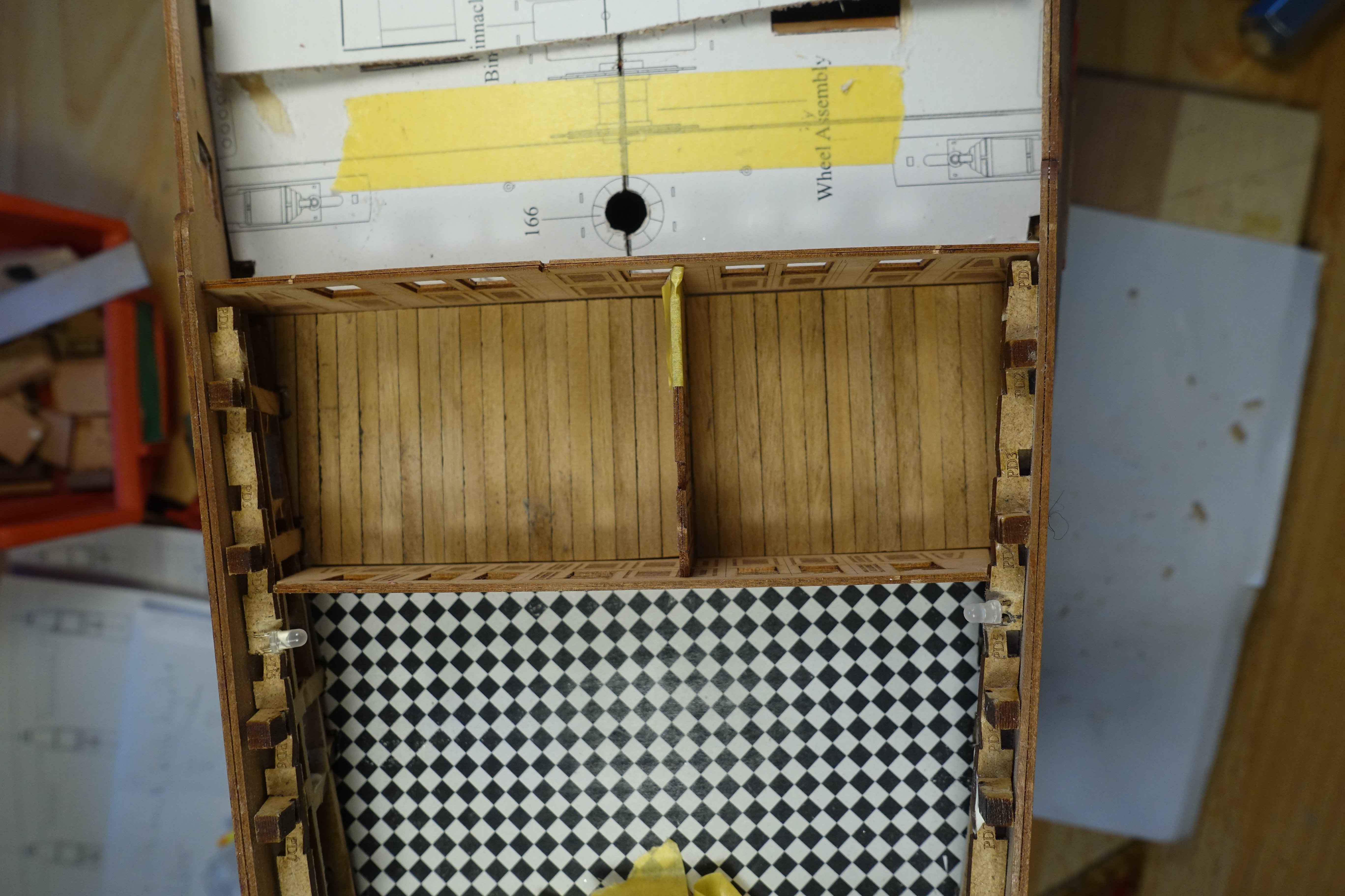
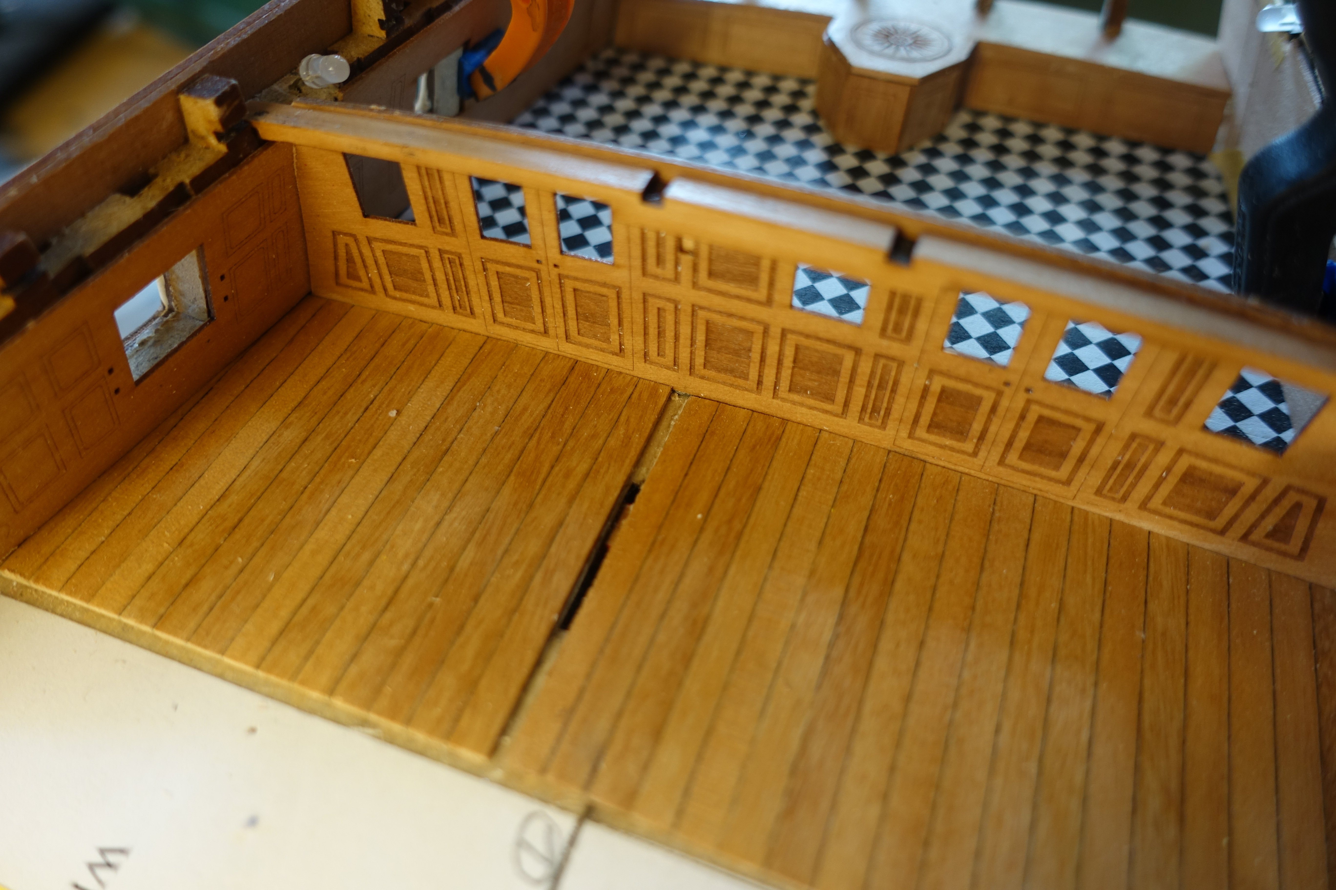
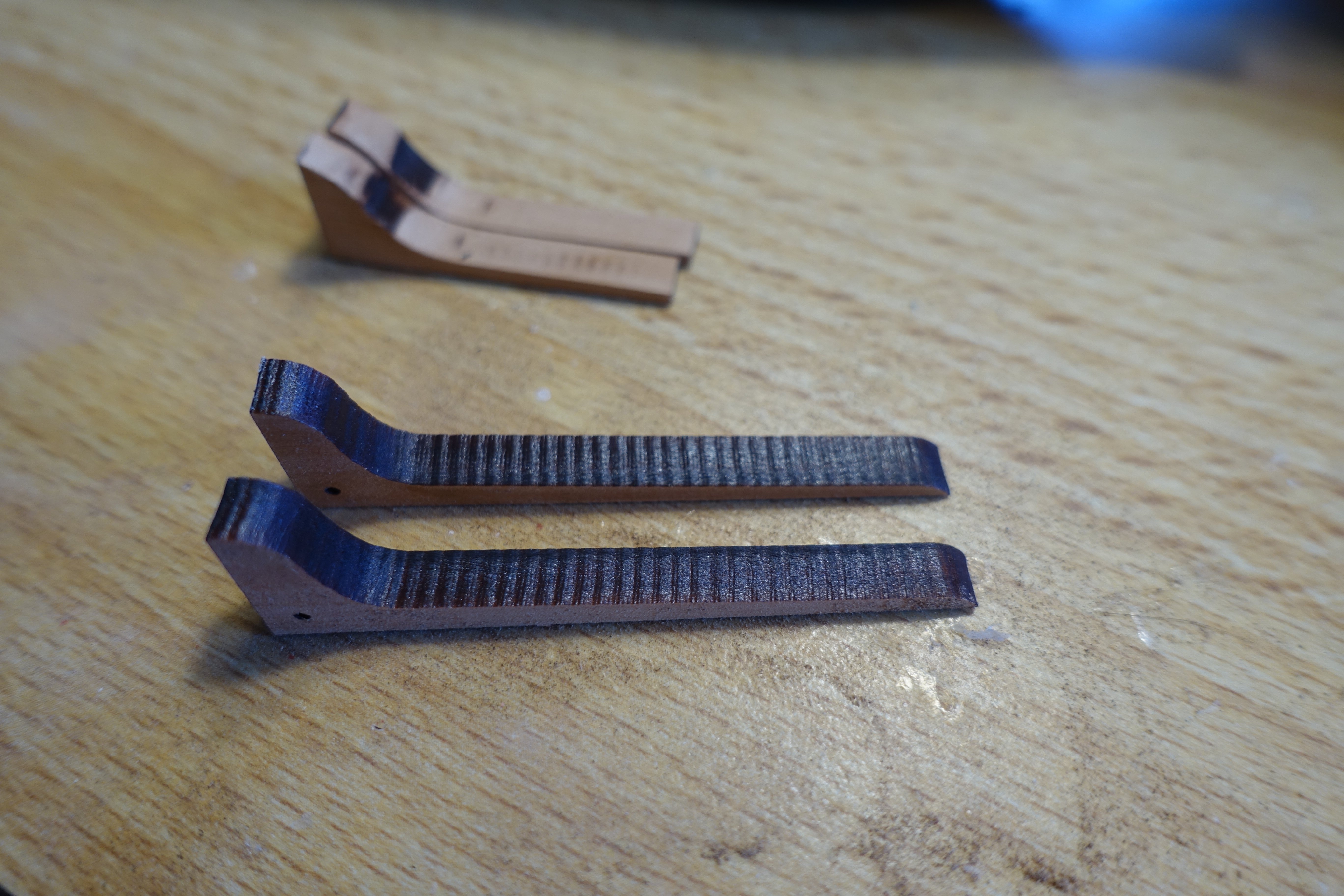
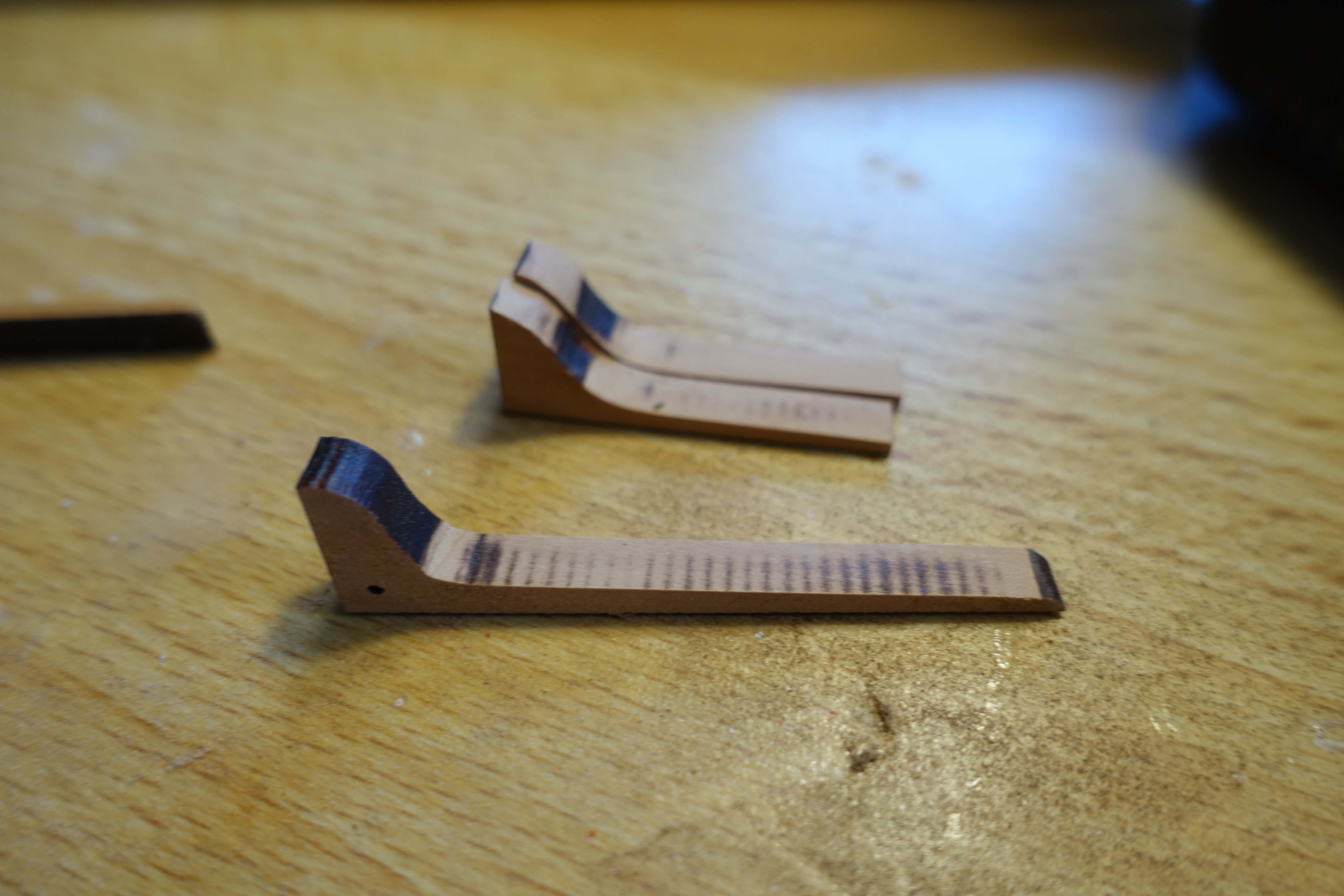
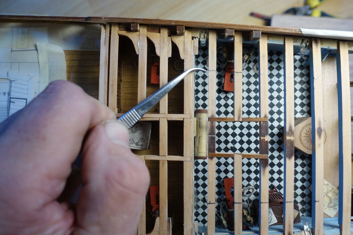
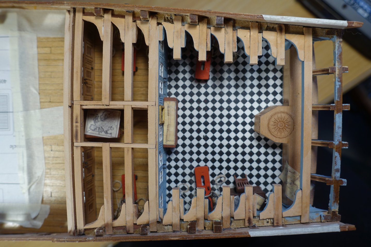
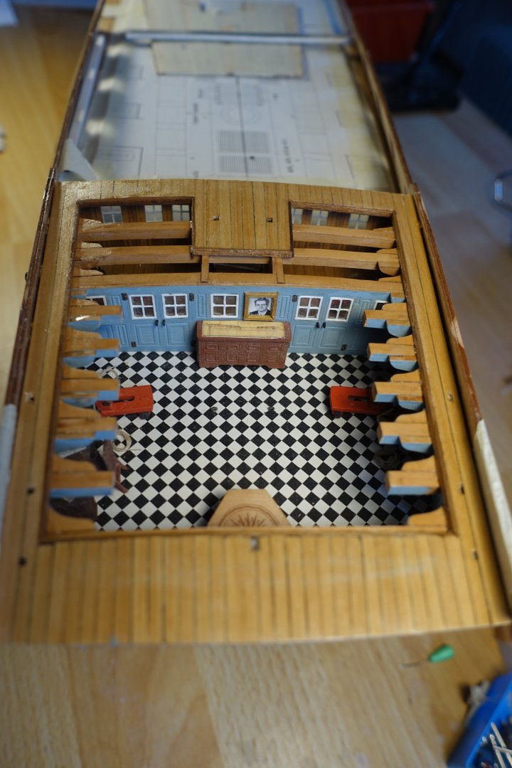
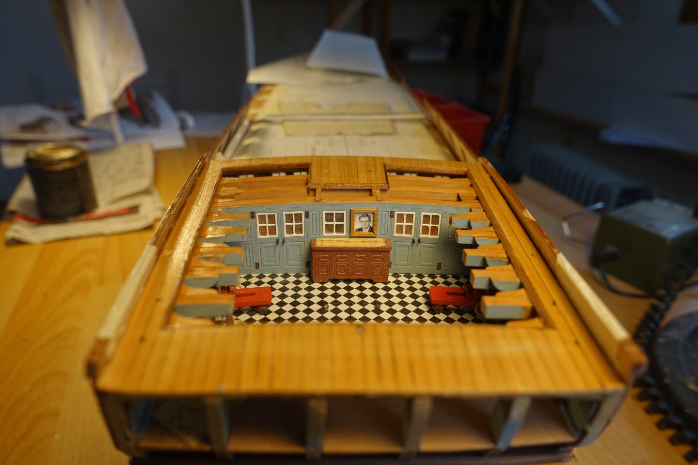
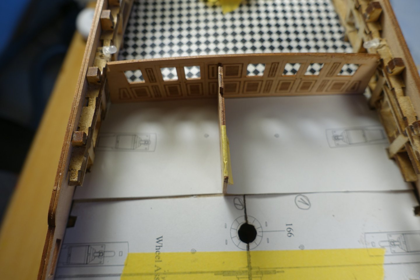
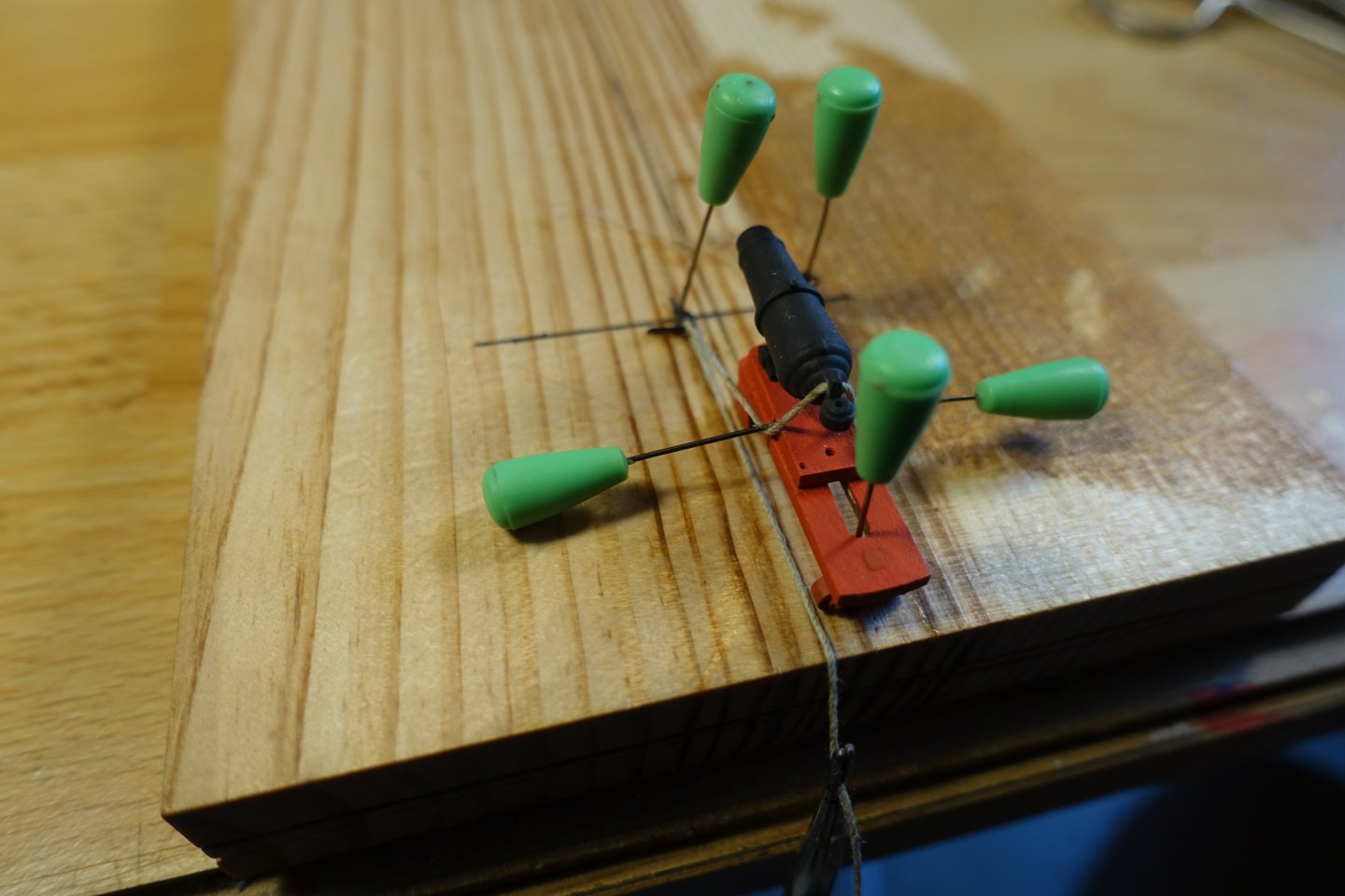
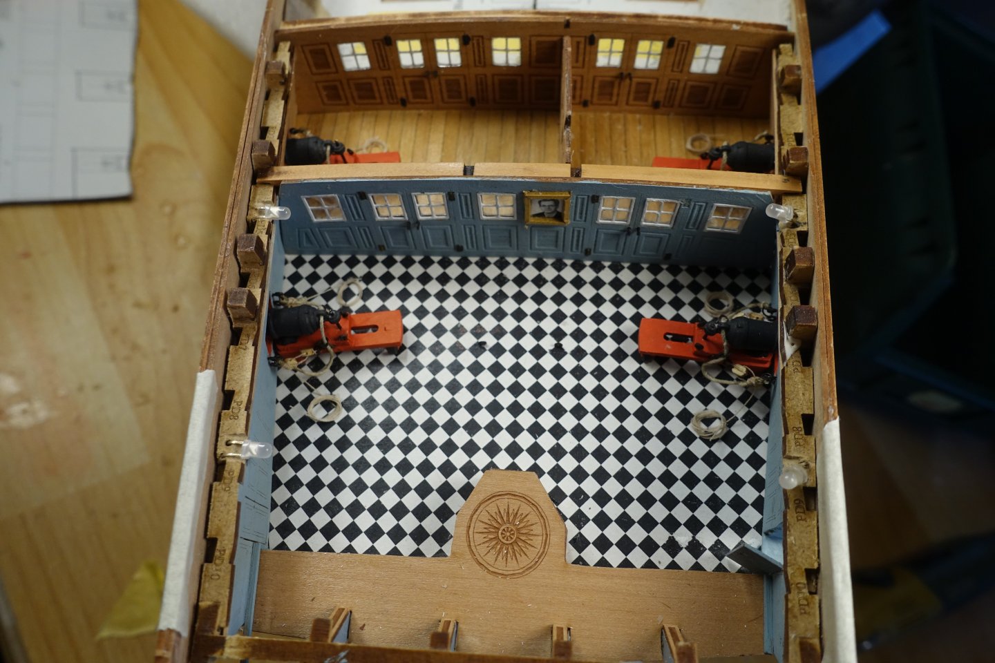
Captain's cabin The bulkheads were adjusted and had to be sanded down slightly. To create the planking between the two bulkheads, I first cut paper to the appropriate size and then glued strips onto this paper. The two groups of strips were then adjusted again. A strip had broken off on one of the side panels. I later covered this (and the other side) with a 1x1mm strip. I wanted to tackle the carronades and first measured the length of the breech rope. Due to the tackle, the slides had to be firmly attached and fixed in place at this stage. In his instructions, Chris recommends making them sliding at first. The captain's cabin is now finished for the time being. As I want to design the poop deck completely open, I will add the furniture later. I am also undecided as to whether I want to add Pellew and officers (doll's house).


-
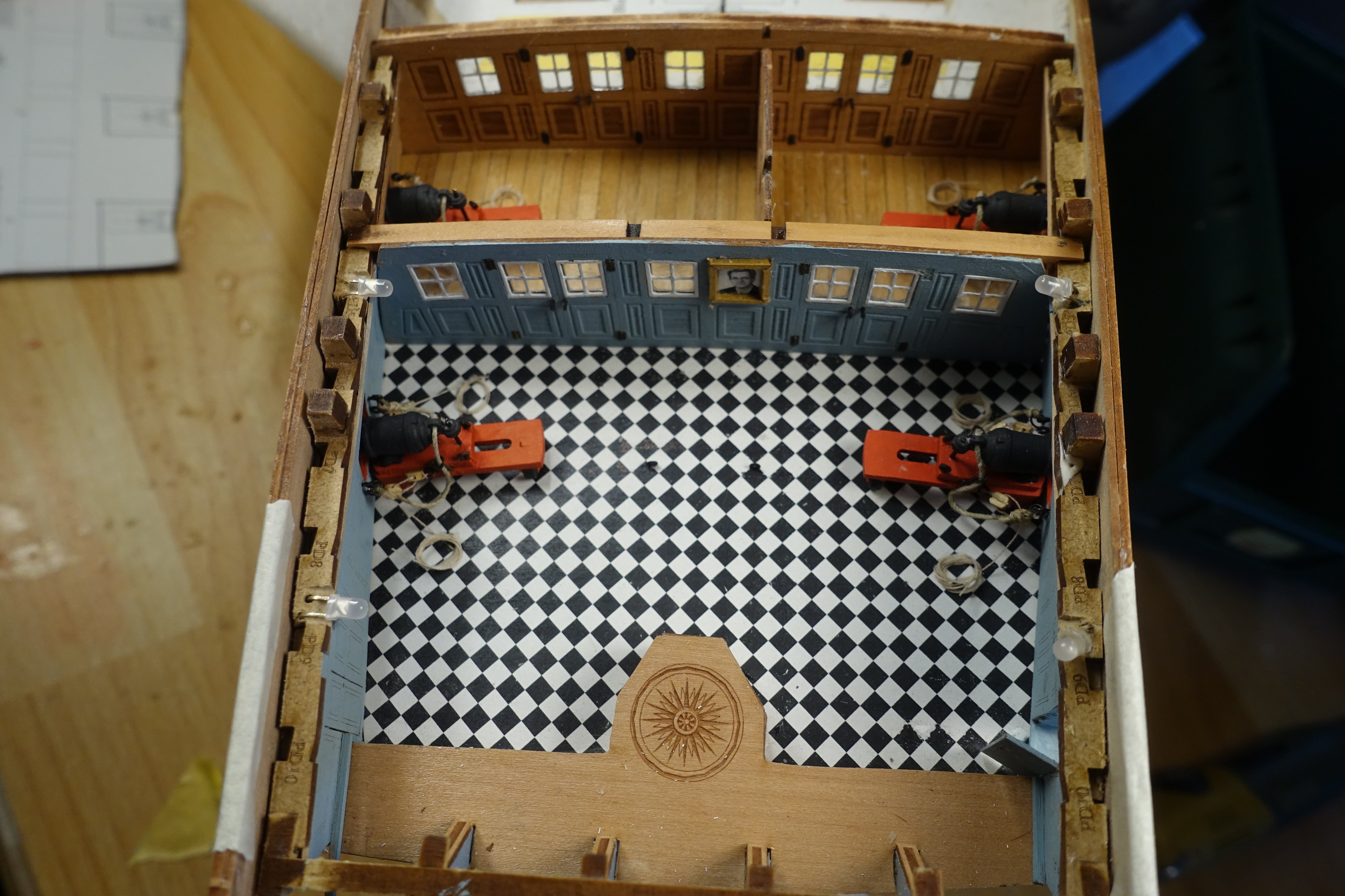
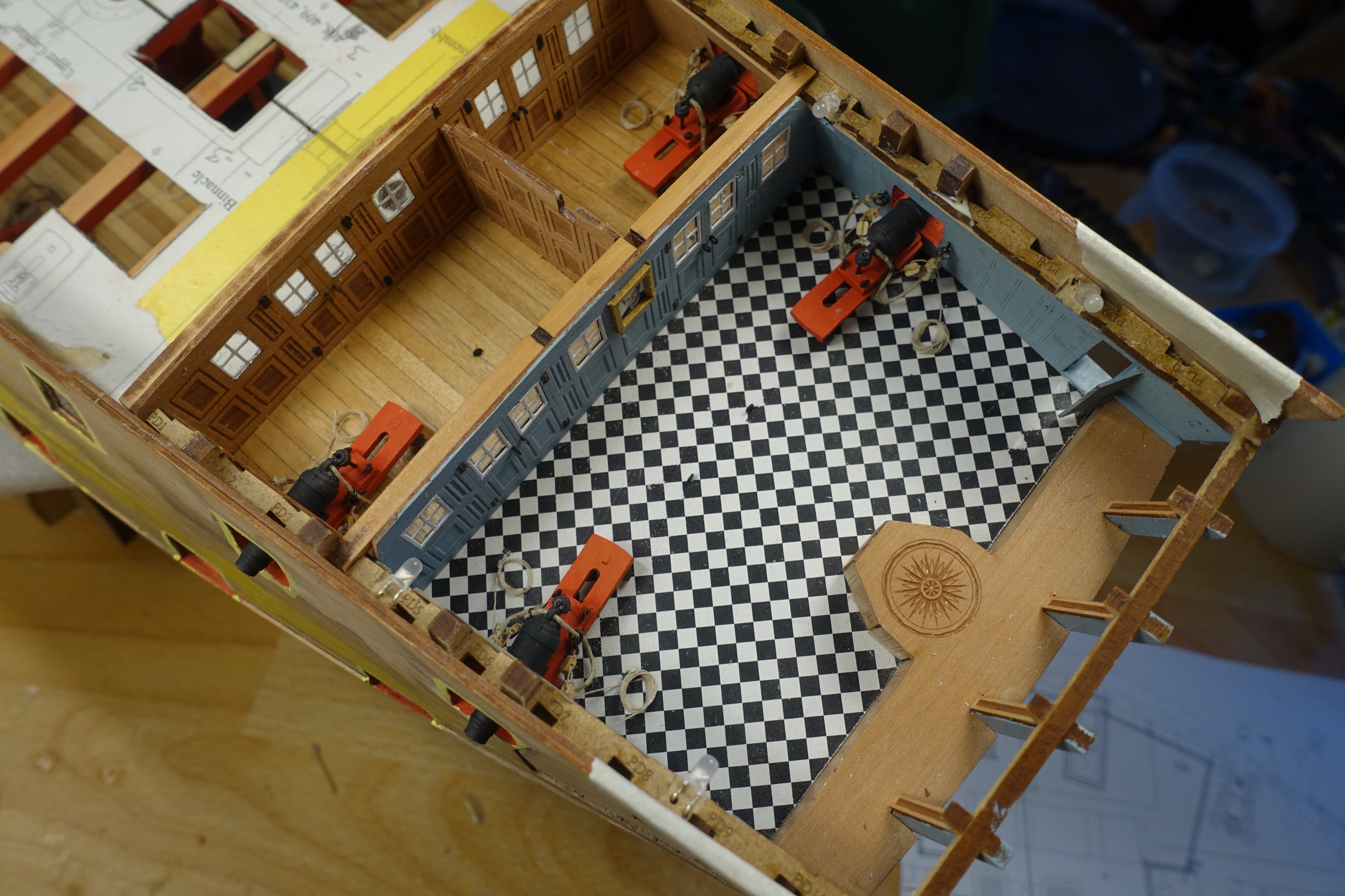
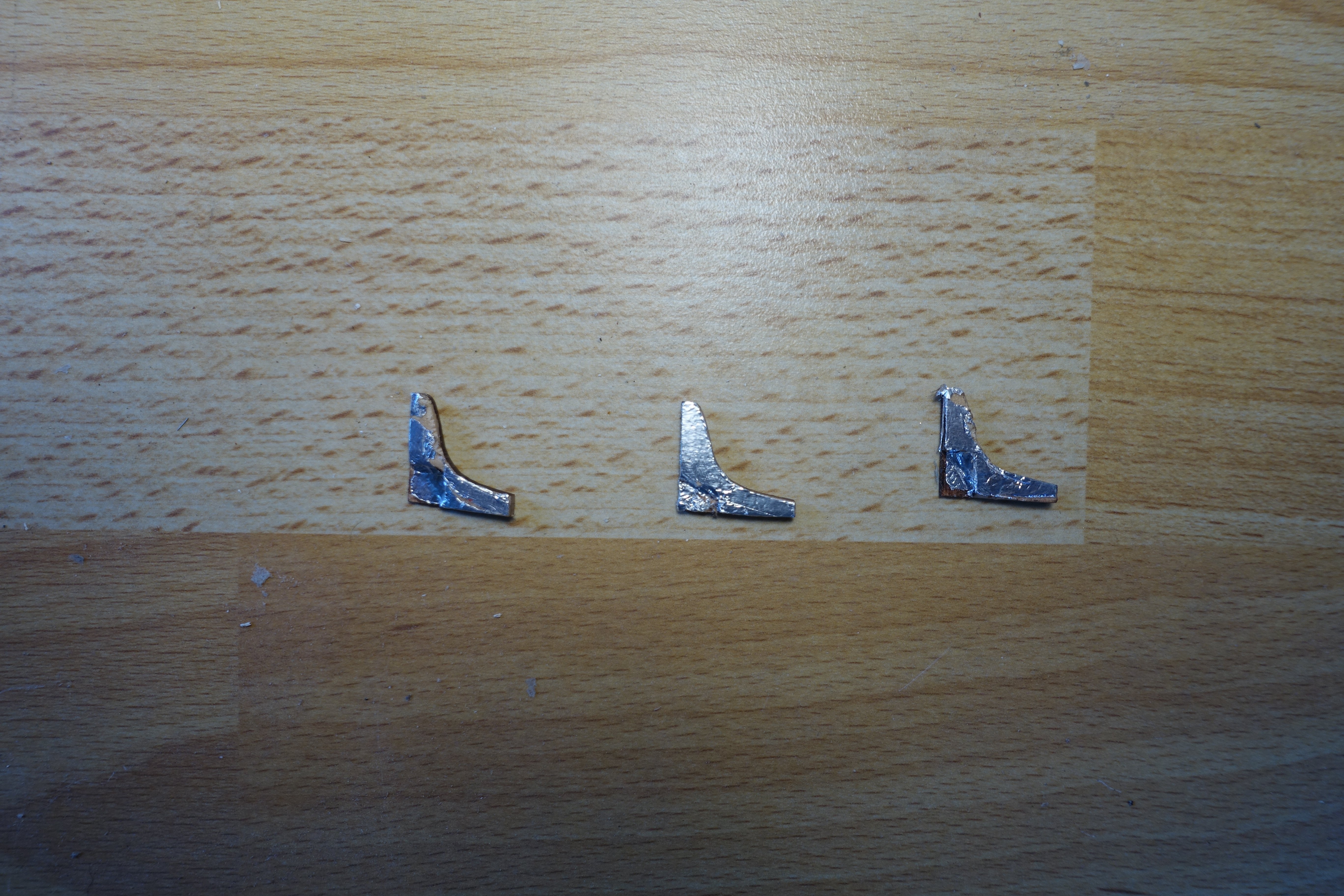
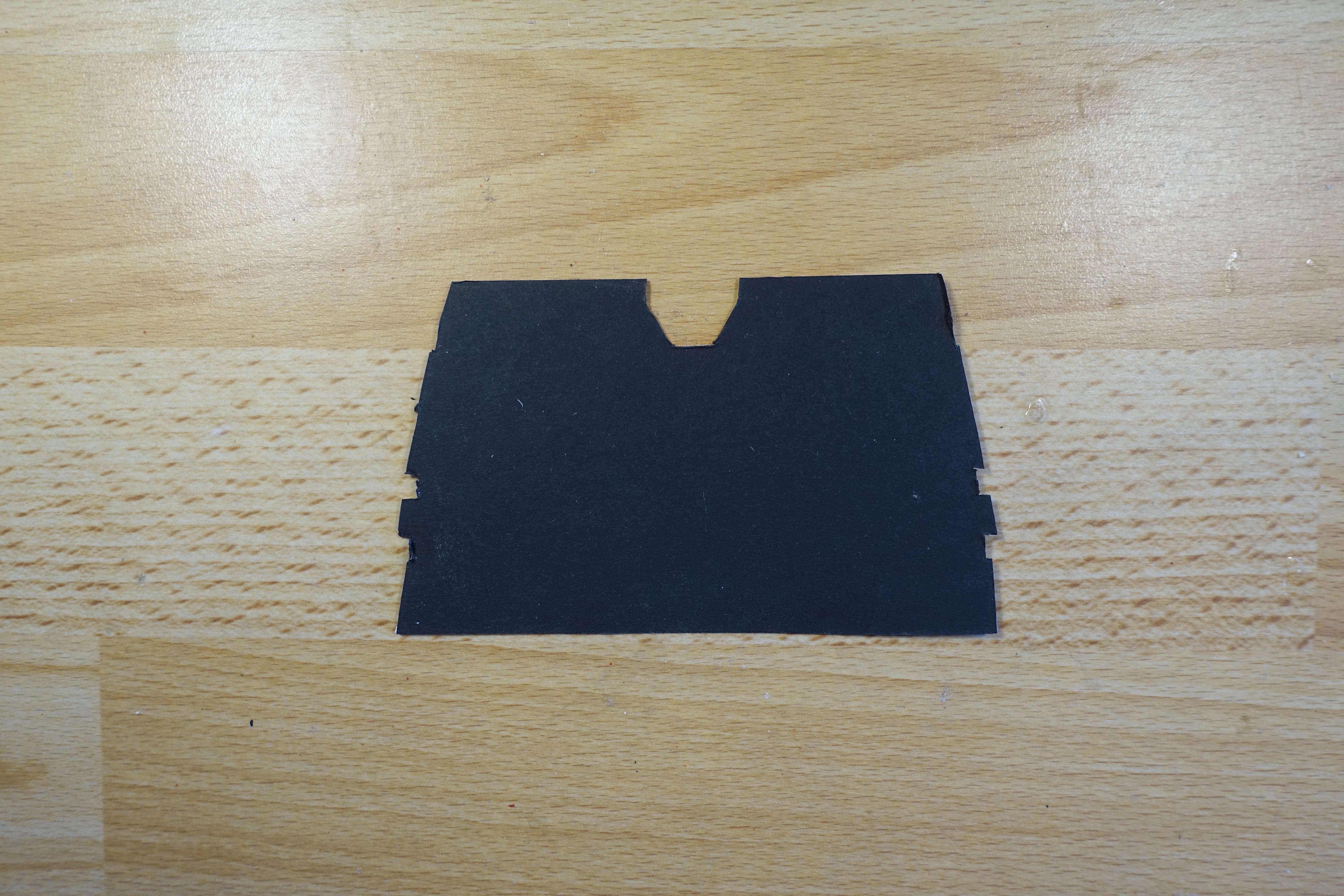
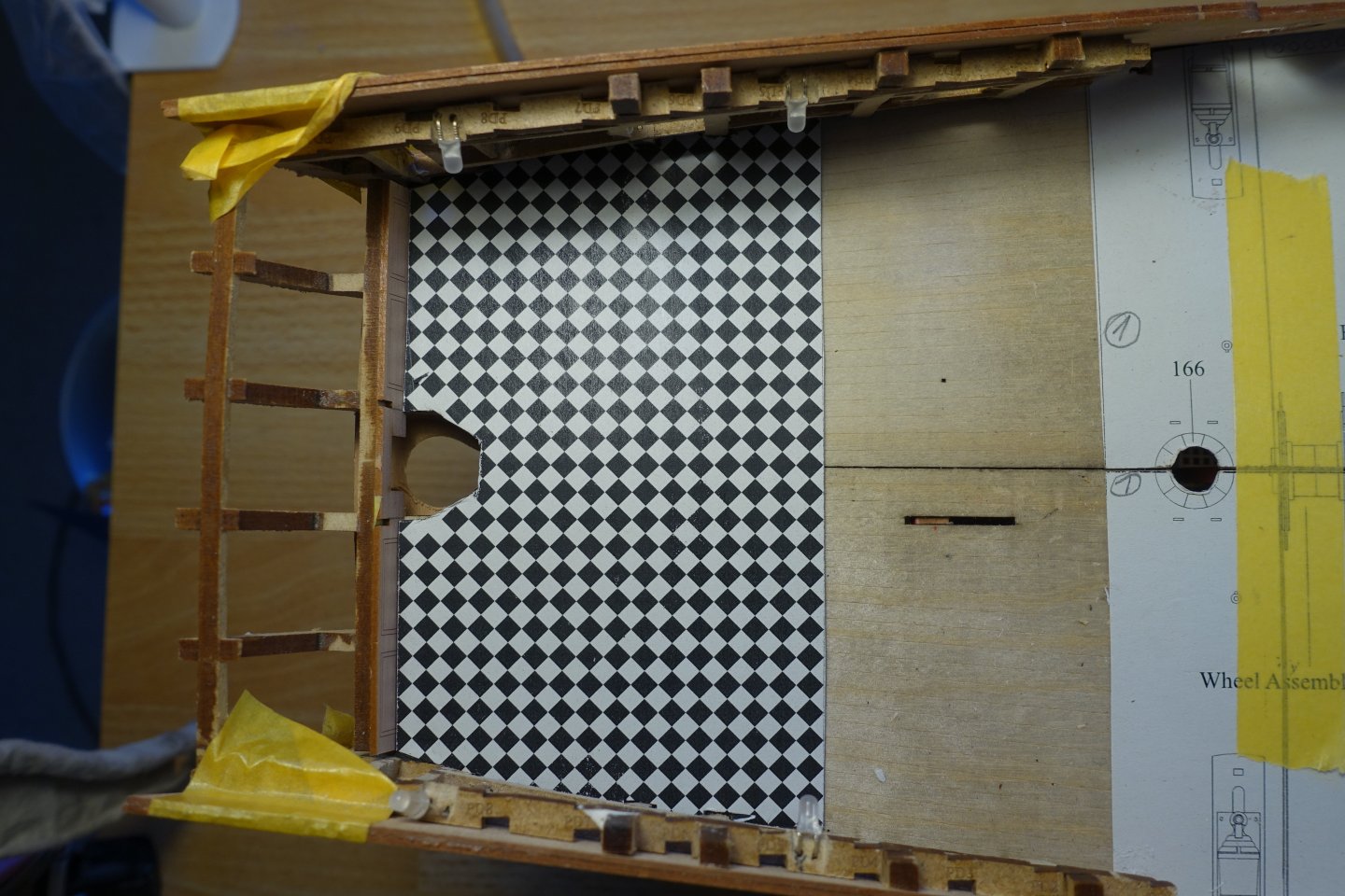
Knees and floor of the captain's cabin The hanging knees required a greater degree of adjustment. Some of the lodging knees still had to be milled out for the LEDs. In addition, the knees above the LEDs were covered with aluminium foil so that they would reflect the light. I used painter's tape to fix the lodging knees in place while gluing them. In some cases, I fitted the knees a little carelessly, but these are areas that are not or hardly visible. The sub-decks of the forecastle and quarterdeck were glued in place. The floor for the captain's cabin was installed. I used black cardboard for levelling and fixing.


-
Thank you very much, even if it probably looks a bit too cosy for a warship. Clark
-
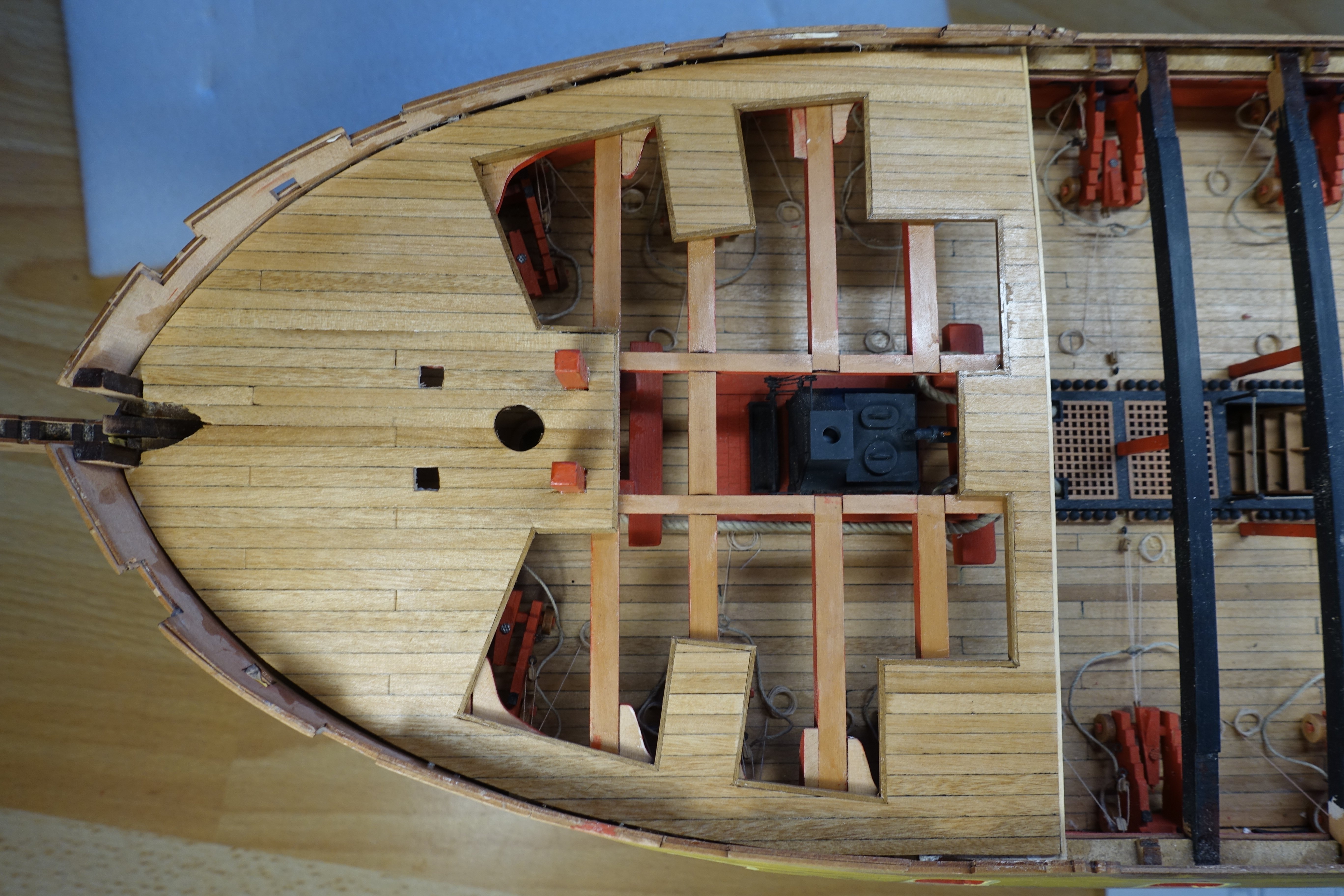
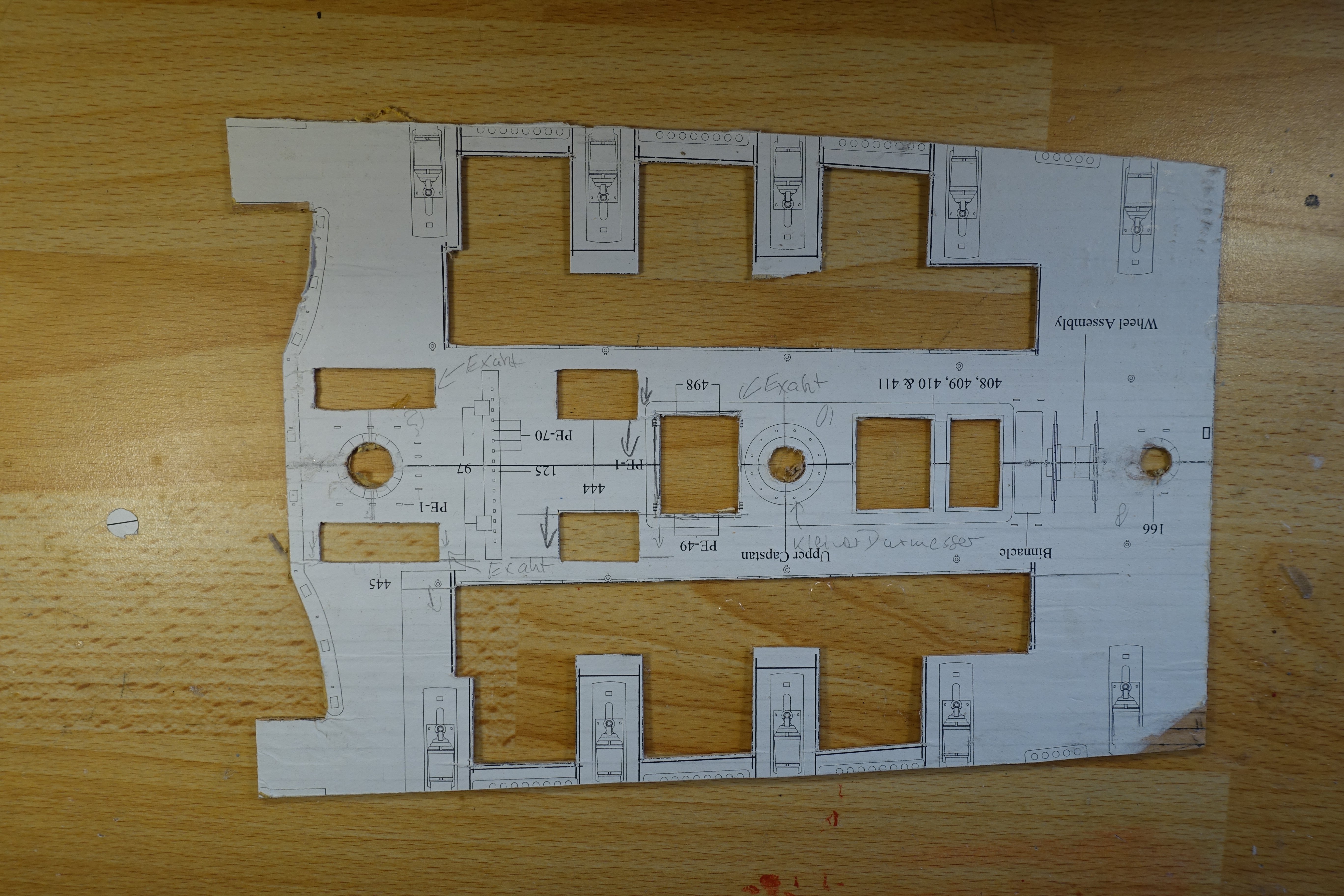
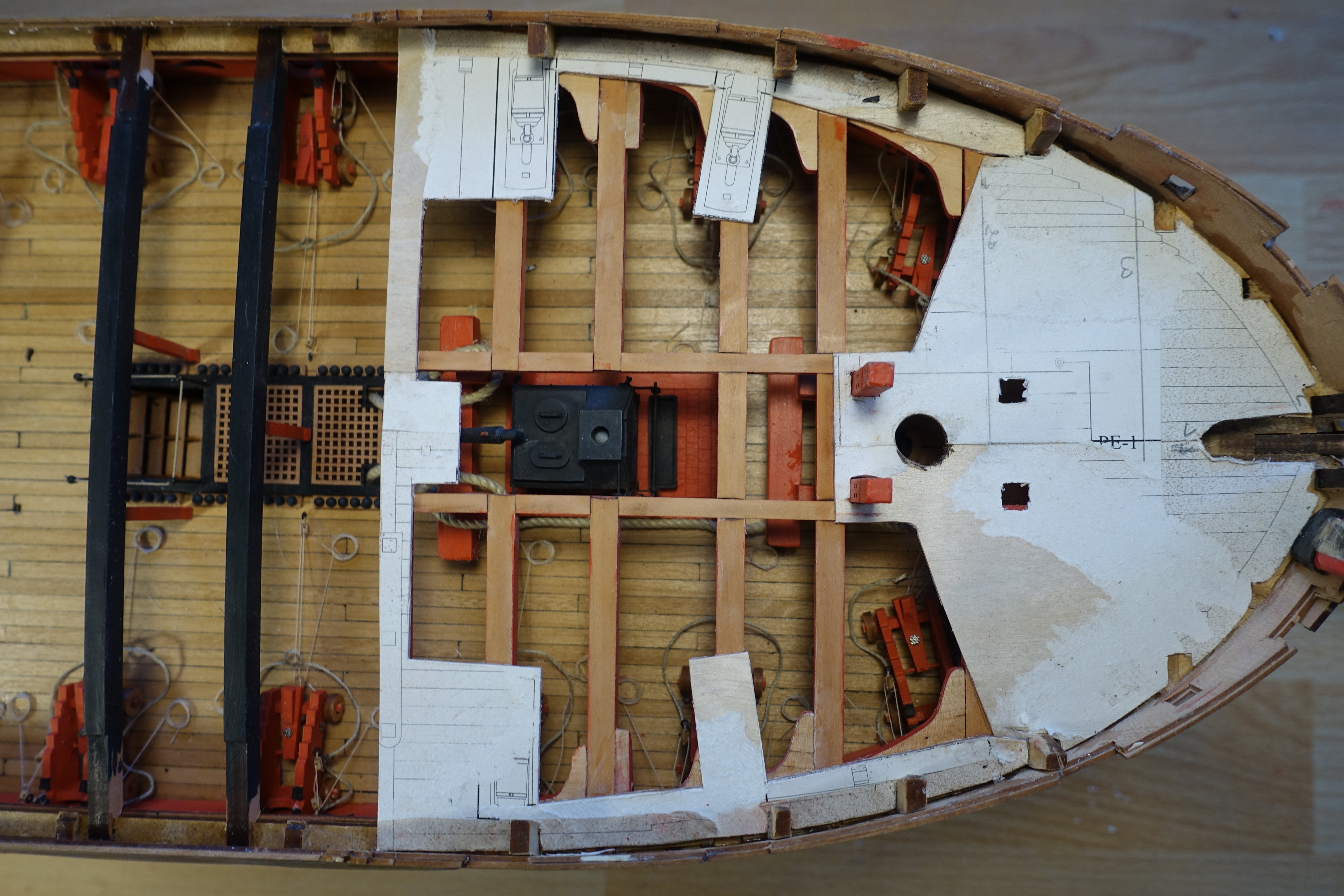
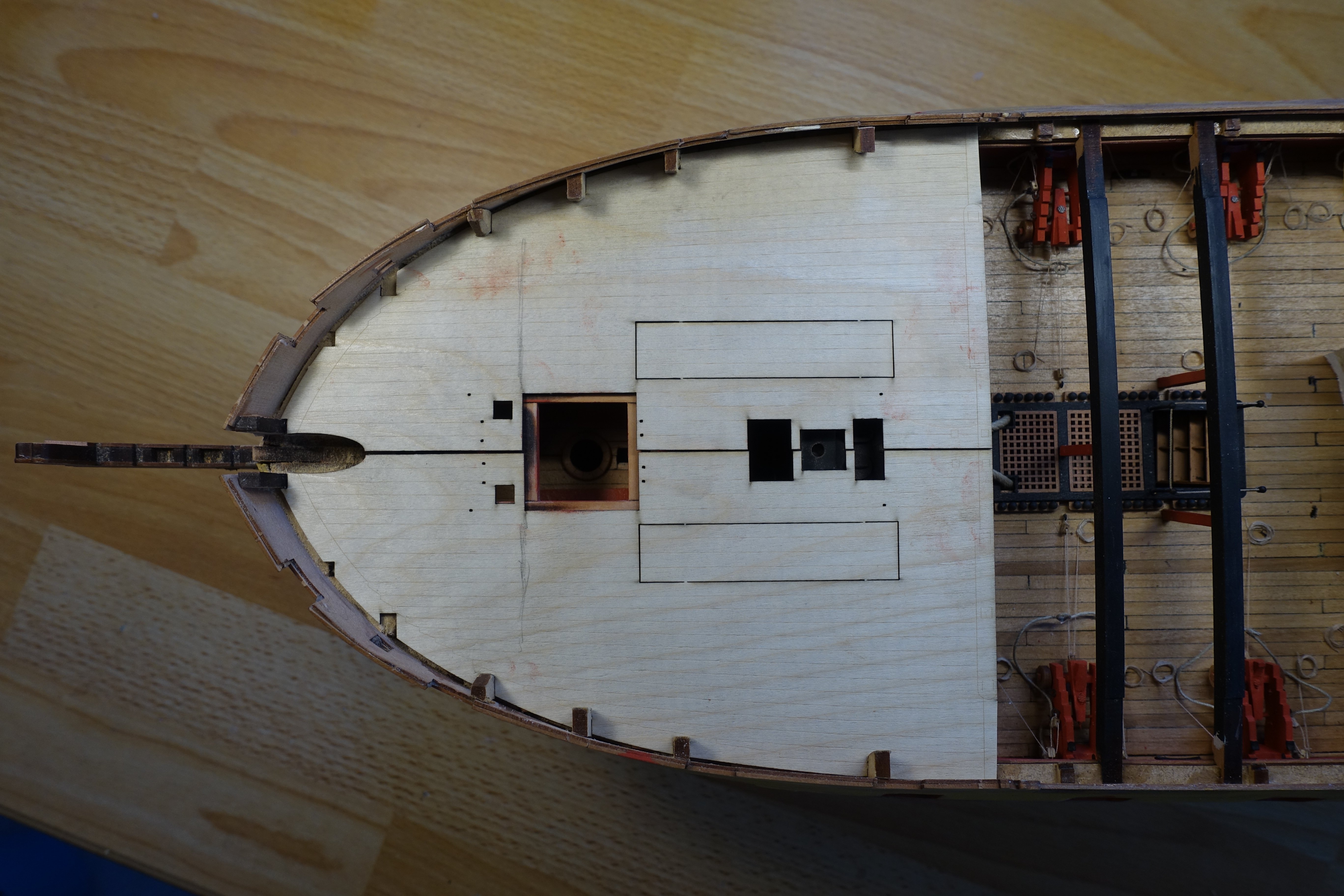
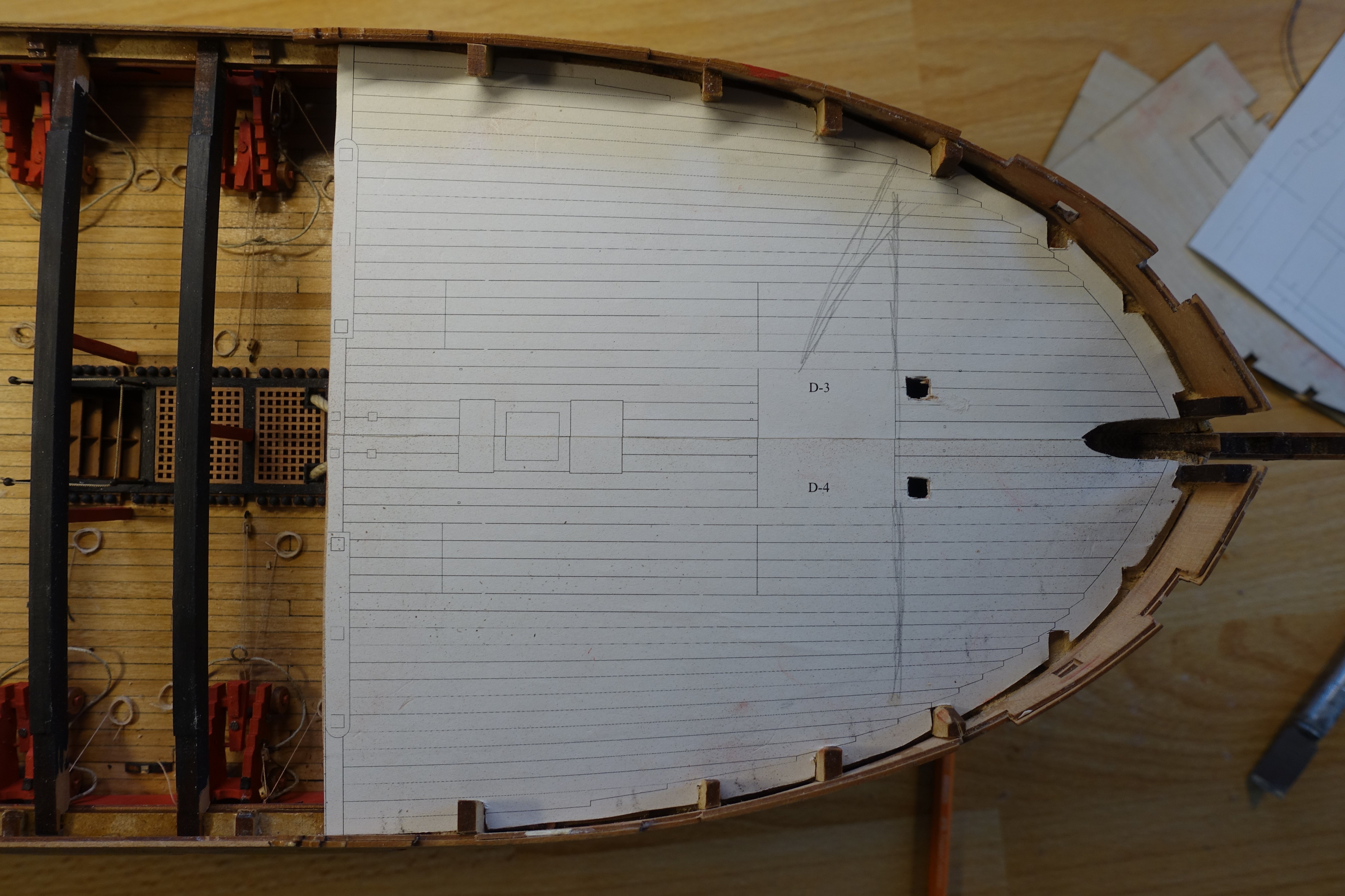
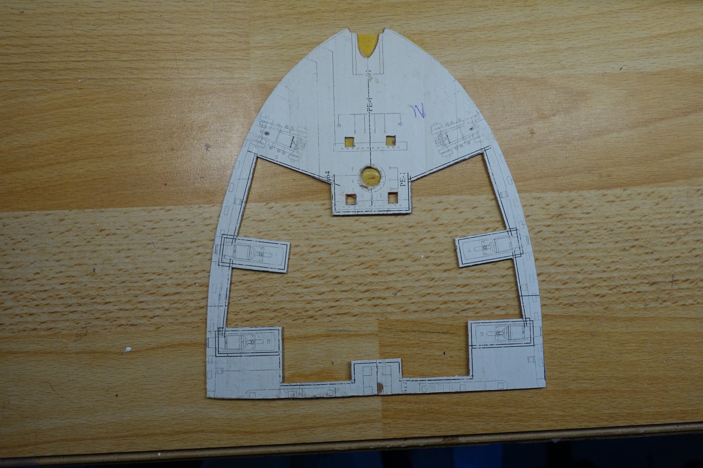
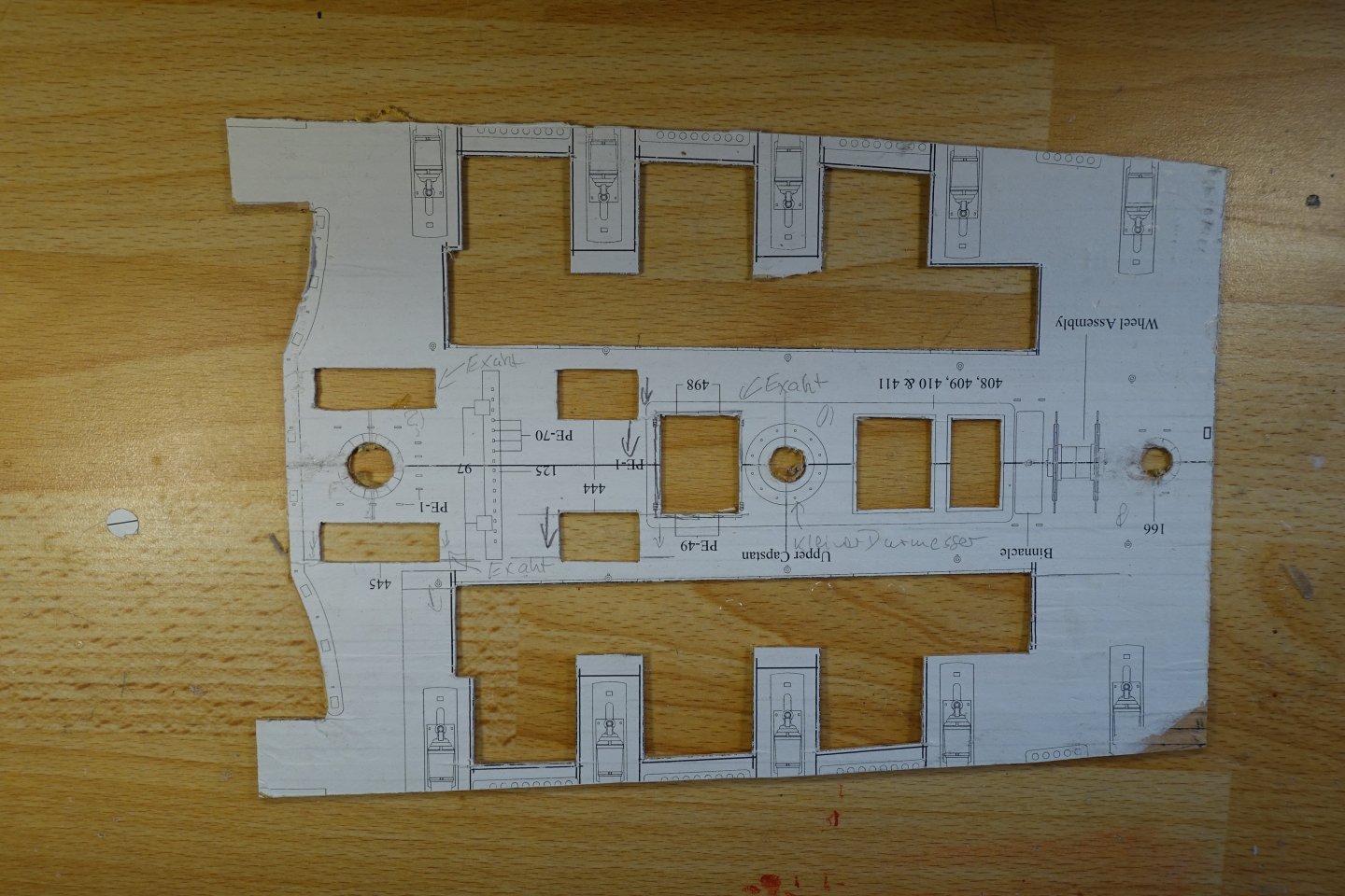
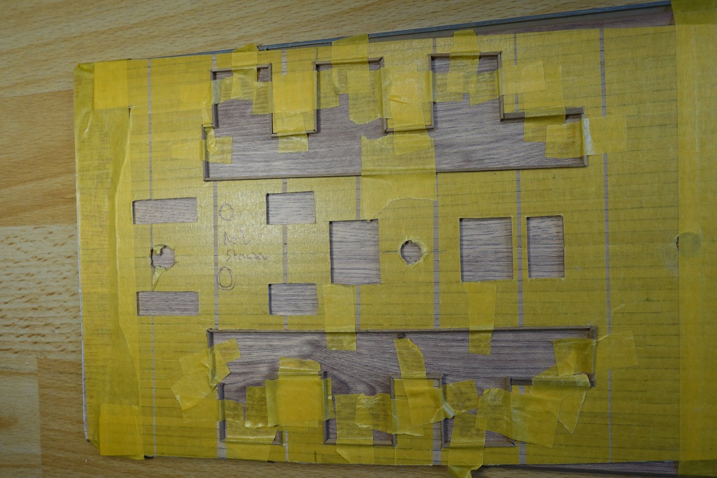
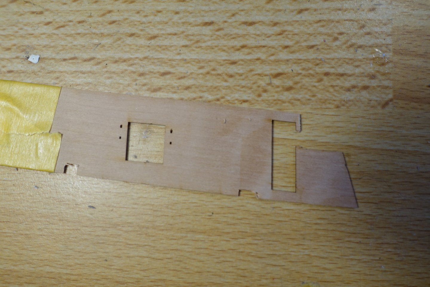
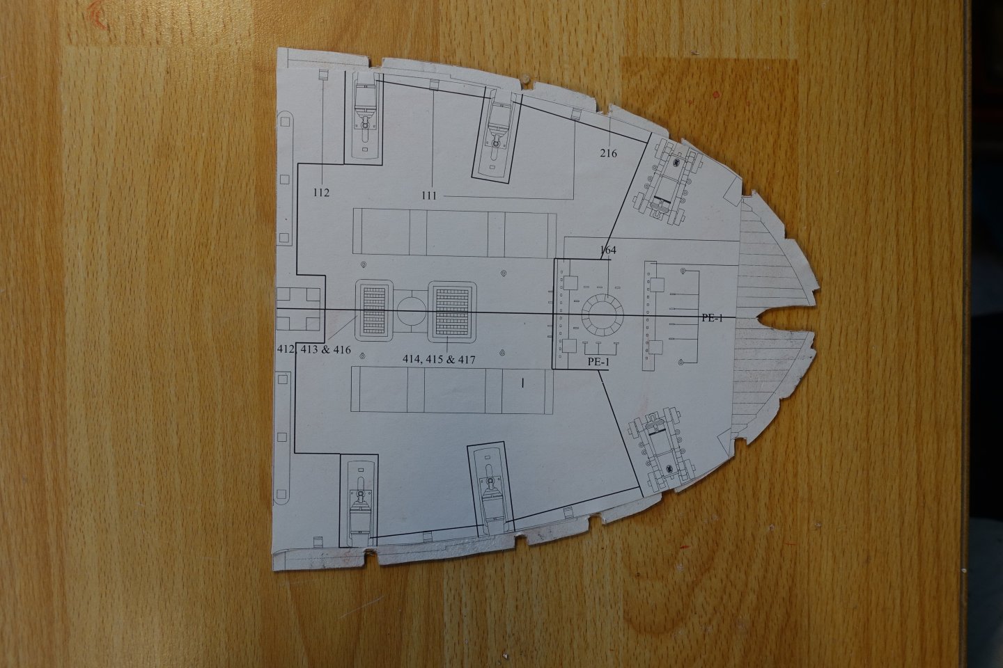
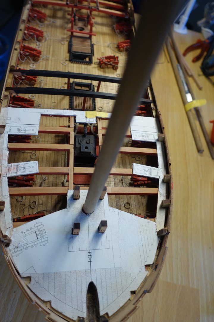
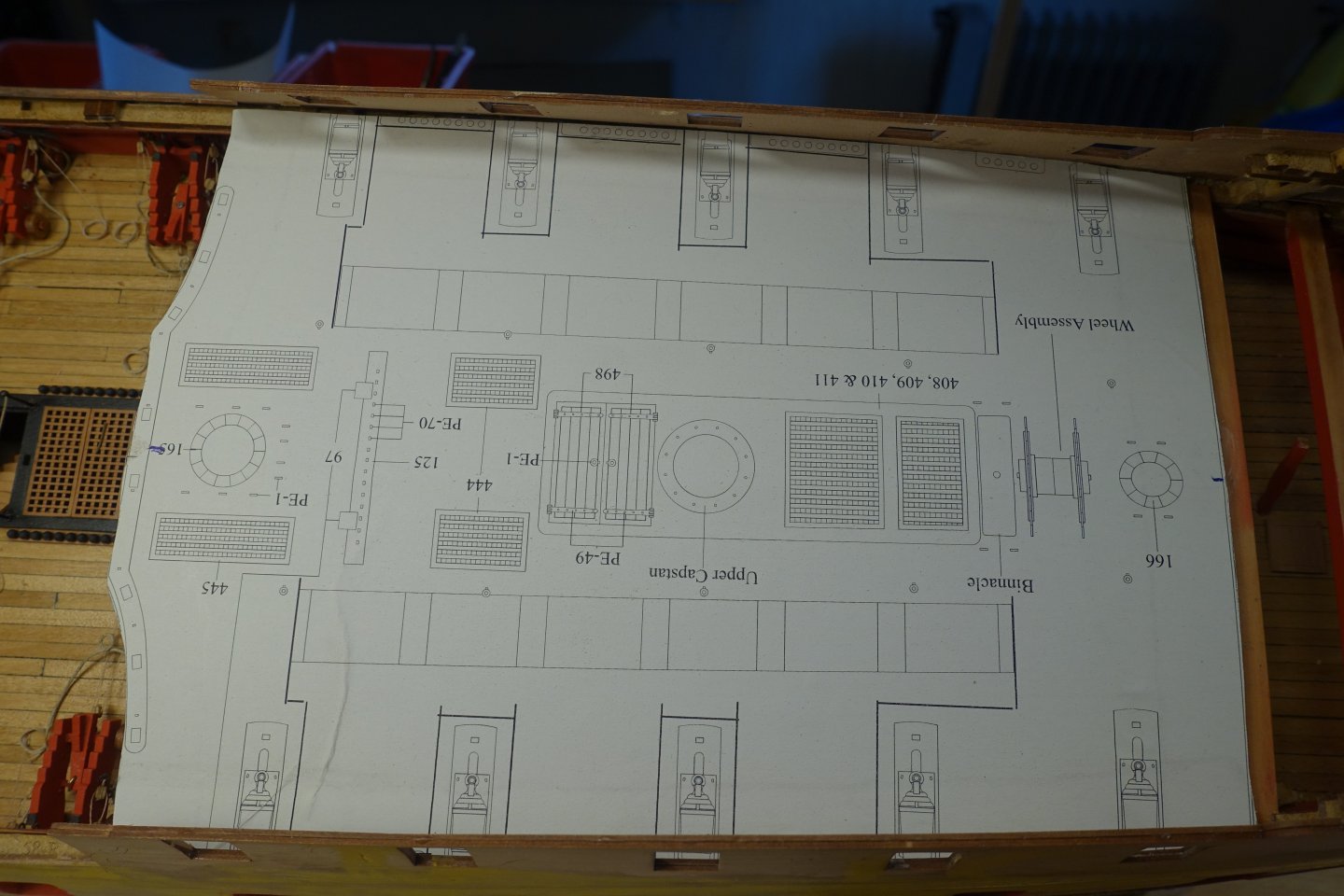
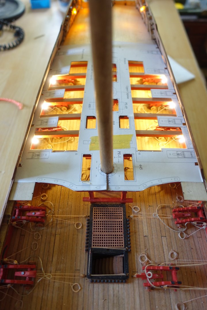
Before attaching the knees for the deck beams, I wanted to adjust the quarterdeck and forecastle deck These should be cut out relatively wide to reveal the gun deck below. For the forecastle, I first checked the fit of the supplied plywood deck. The frame ears had to be notched a little further for this. I then made a template out of 0.8 mm plywood. I then transferred the planned cut-outs onto this template. The template deck was cut out and fitted. It was important to me that the bases for the carronades were centred in front of the gun ports. Although minor corrections habe to be made, I will then use this for the planking. I proceeded in the same way with the quarterdeck. On closer inspection, however, the plywood bridge at the board side seemed too narrow to me. So I moved the cutting lines towards the centre of the deck. The cut-outs were made on the supplied deck halves, with the quarterdeck being separated beforehand. The angle of view is somewhat misleading here, but here too, the bases for the carronades are located centrally in front of the gun ports. Finally, I checked how the LED would look. 6048


-
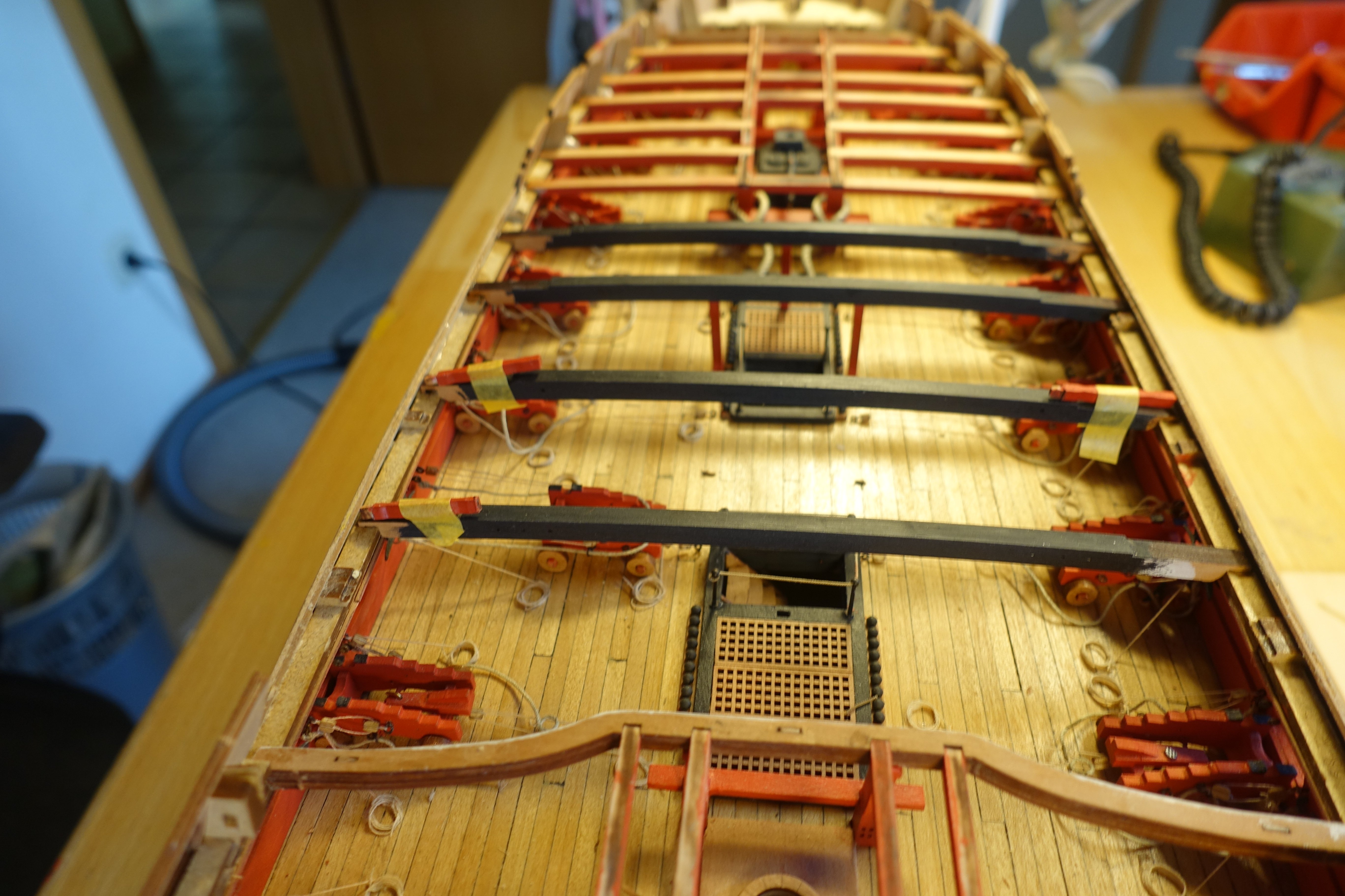
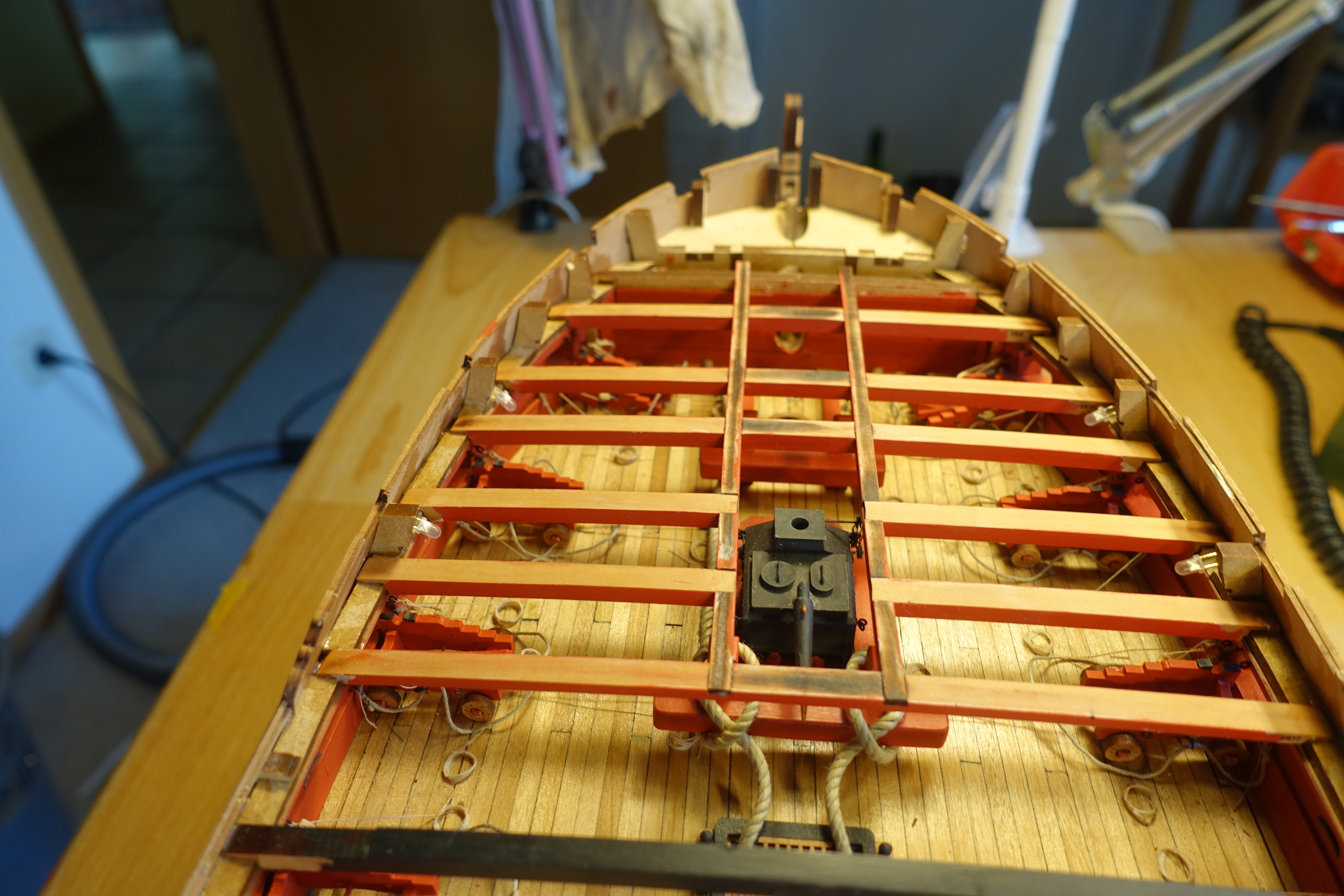
The beams were painted and coated with clear varnish and then glued in place. Several beams were inserted and the levelling was tested using two 10x10mm pieces of wood and then diluted PVA was applied to the joints on the MDF. In this way, the levelling was easily maintained. The anchor rope was laid The first beam at the bow has been panelled. I want to open the forecastle deck relatively wide and the panelling should cover the MDF behind it. The opening for the bowsprit was tested with a 10 mm dowel. The deck beams are largely in place. The two stern boat beams and their supports are not yet attached, as I still want to attach the gun crew and need space for this. The end beam of the quarterdeck has not yet been attached or painted. To level it, I had to deepen the cut-outs for the bitts by about 0.3 mm.


-
You're right. I just wasn't sure if I had done something wrong. Thanks for stopping by.
-
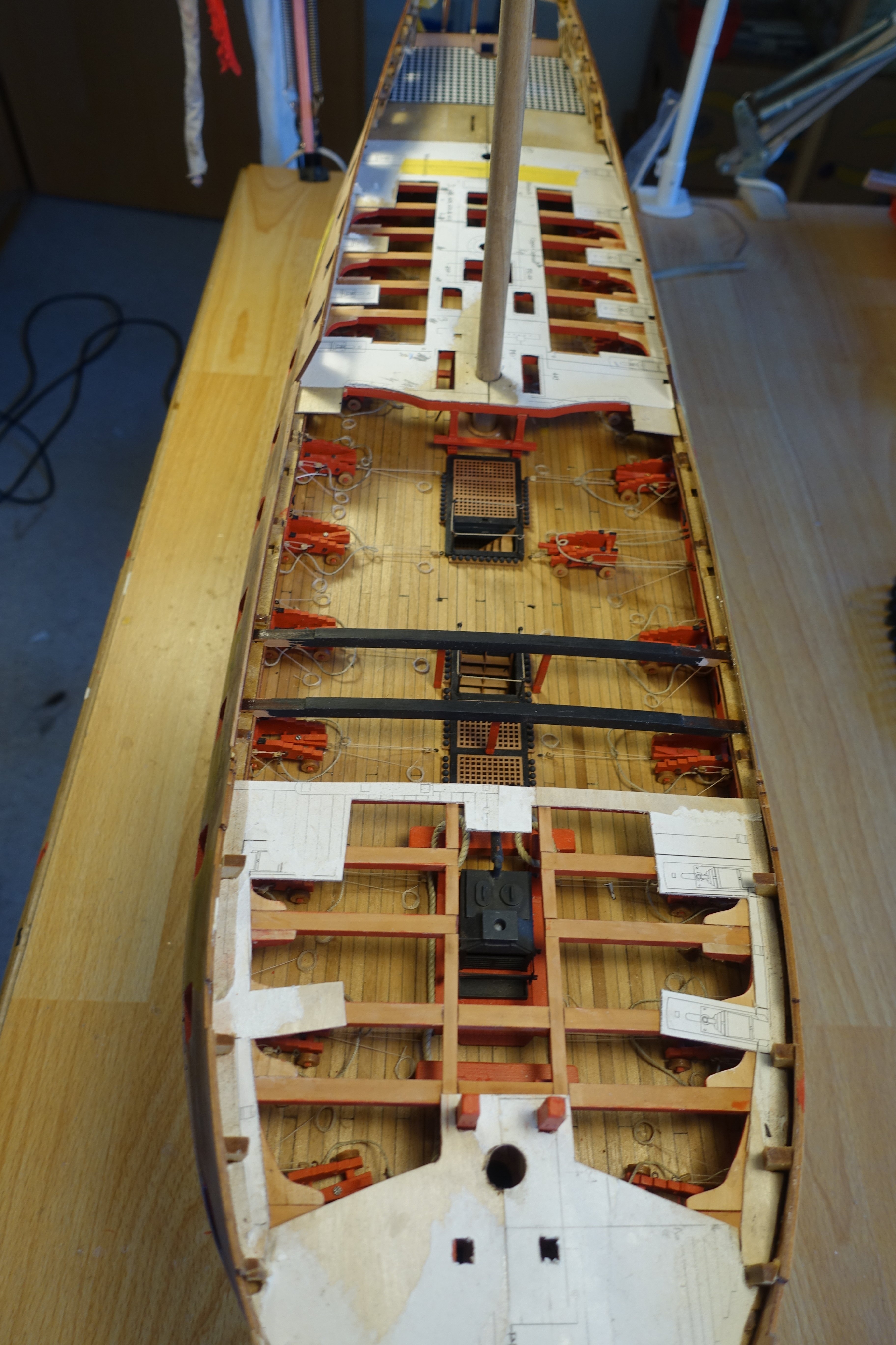
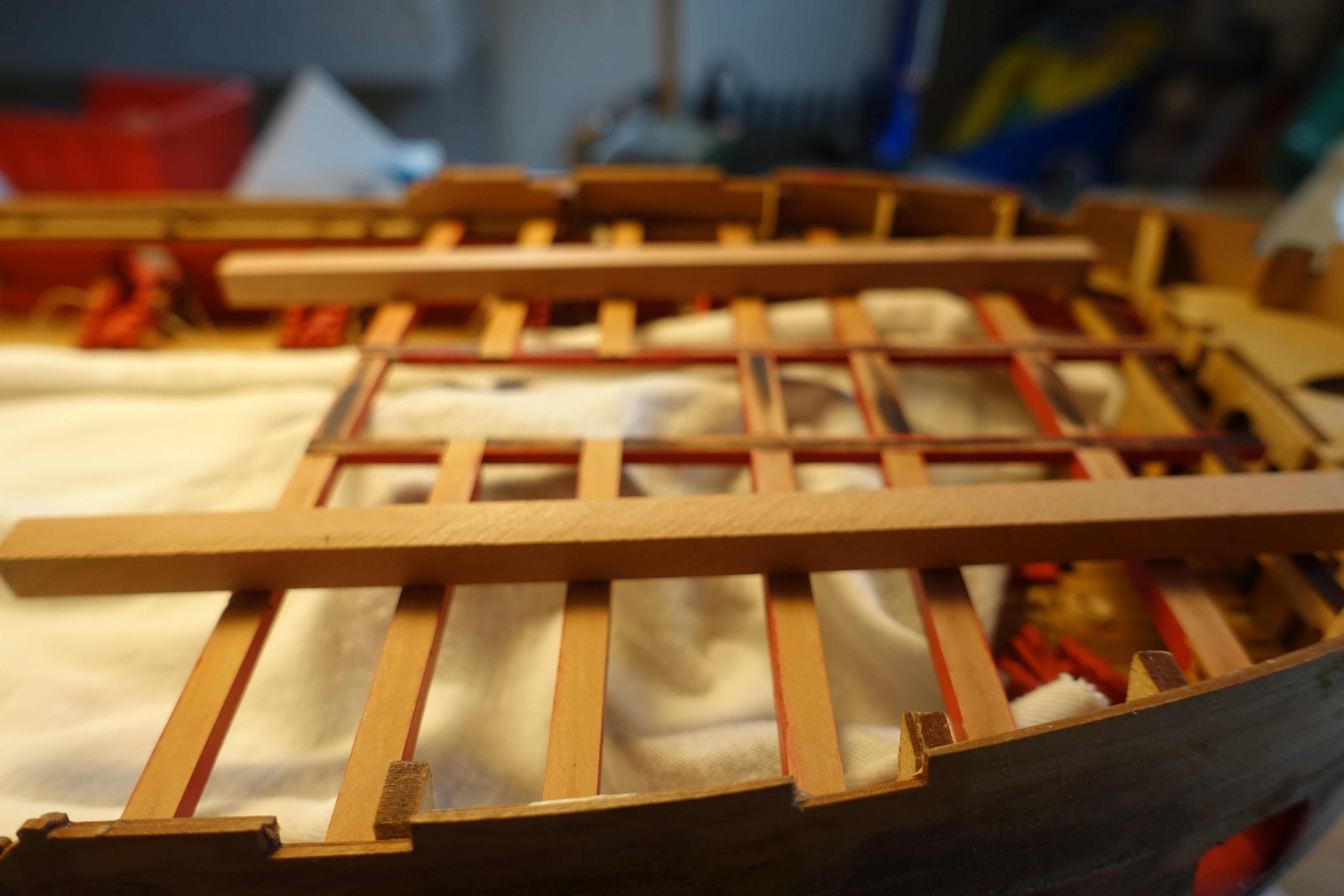
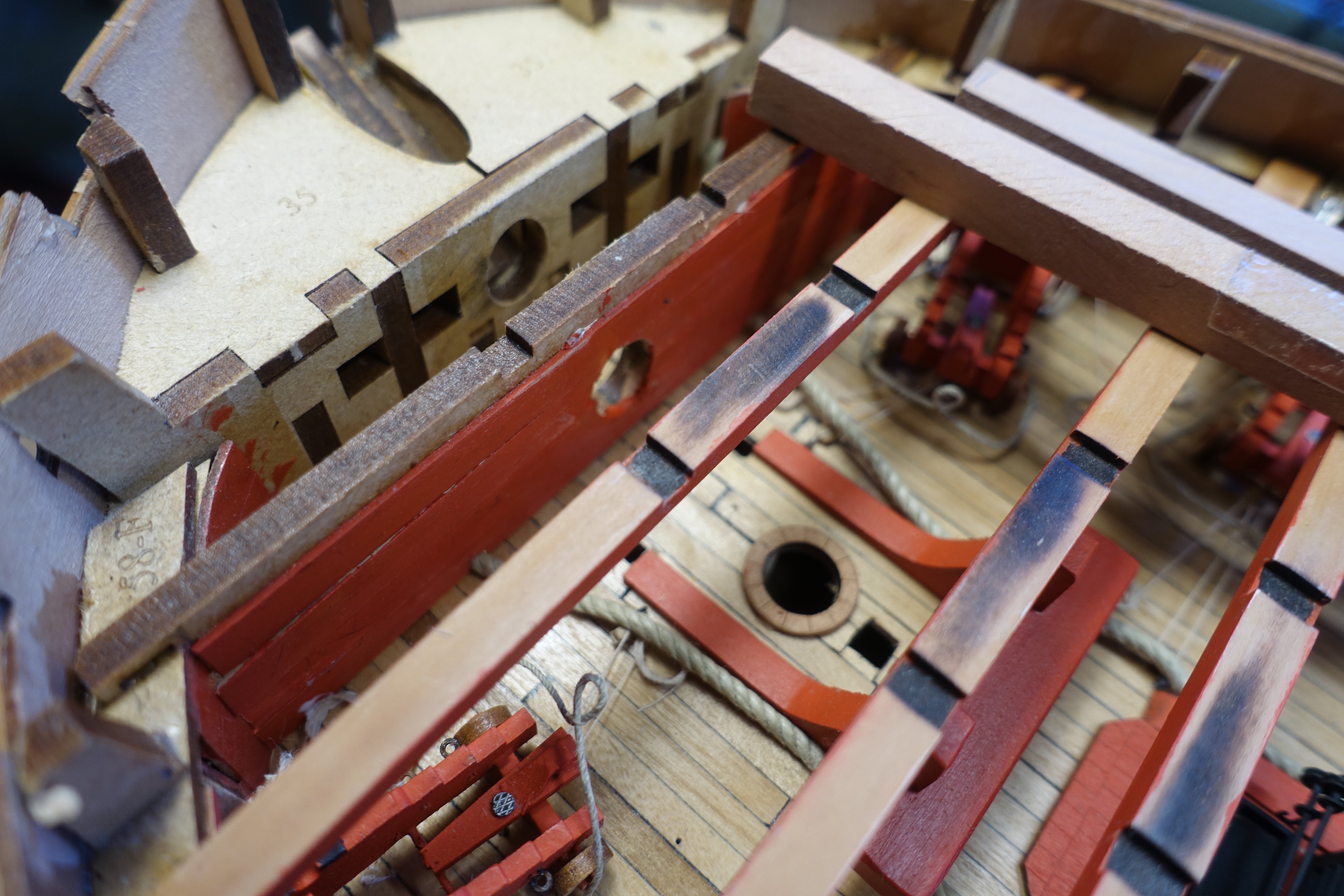
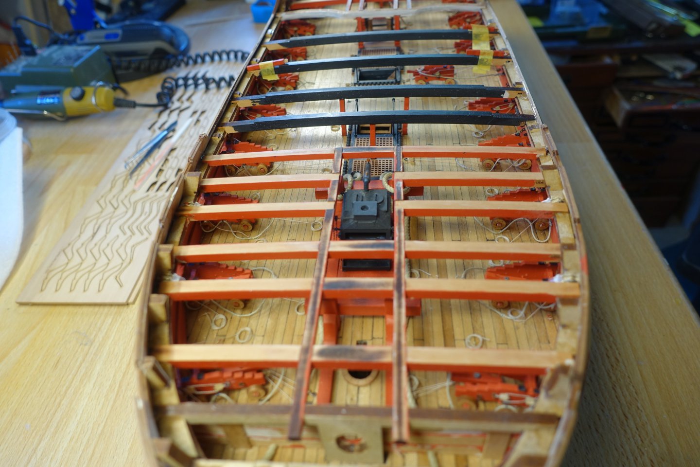
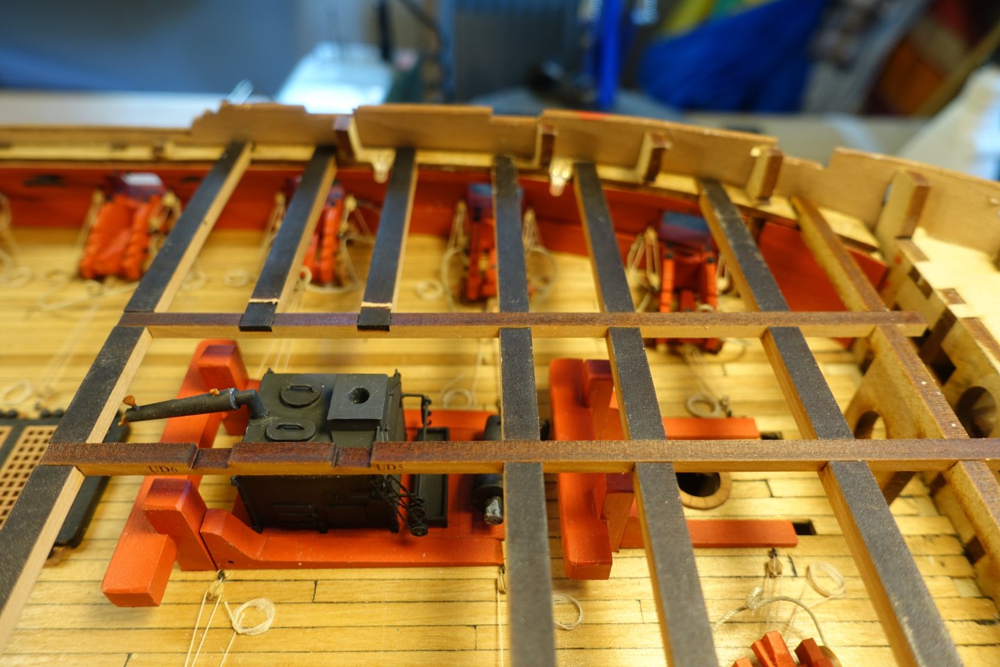
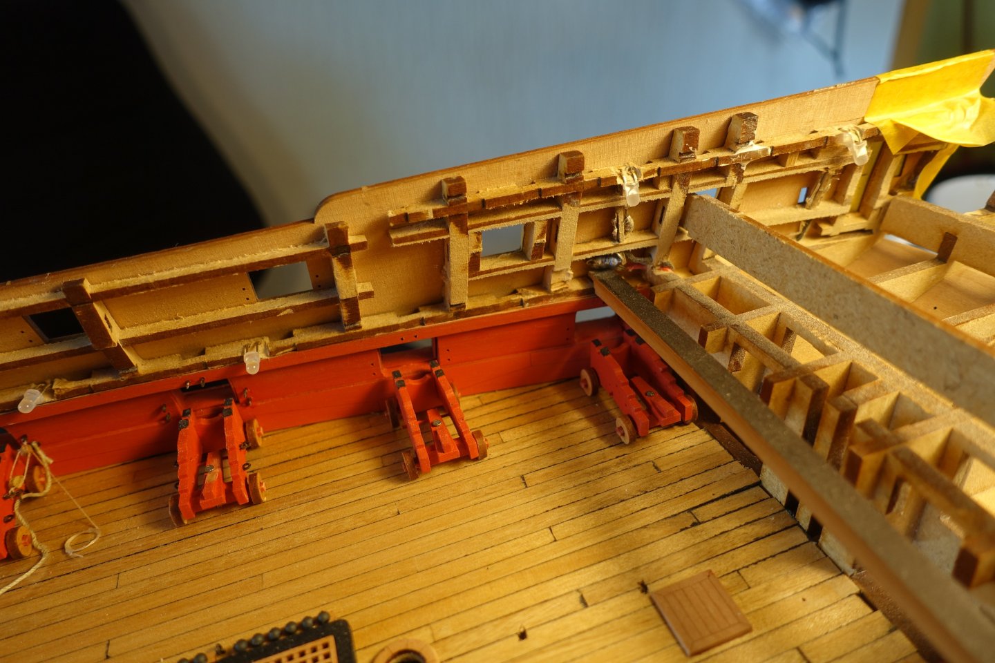
-------------- Deck beams Attaching the deck beams proved to be somewhat more difficult. A lot had to be filed down or removed. For the beams for the forecastle deck, simple bevelling was sufficient. The levelling was checked both in the centre and on the side. Fitting the deck beams of the quarterdeck was more difficult. On the one hand, a relatively large amount had to be sanded off the beams themselves. However, this was still not enough. In order to fit them, I had to remove a relatively large amount of the vertical MDF structures, partly restricted by the wiring for the MDF lighting. I filed alternately on the starboard and port sides to create additional space for inserting the beams. For the second deck beam (QD9), I had to file down the bitts a little, otherwise it would have been too high in the centre. The bitts will later be sanded smooth and painted over. The levelling of the quarterdeck beams was also checked in the centre and on the ship's side. One deck beam (QD 14) is missing in the picture. This can only be fitted once the longitudinal beams have been attached. There is a small note about this on the plan and also in the Blue Ensign description. When attaching the longitudinal beams, I noticed that they are not parallel. 793 790 791 However, the lack of parallelism corresponds to the plan.


-
Just a short update The metal parts for the stove have been etched so that the primer and paint will adhere later. The stove was made, painted and glued in place. Ladders, cannonballs and pumps are also attached.


-
Thank you for the compliment, but I was just following Chris and James' suggestions. Clark
-
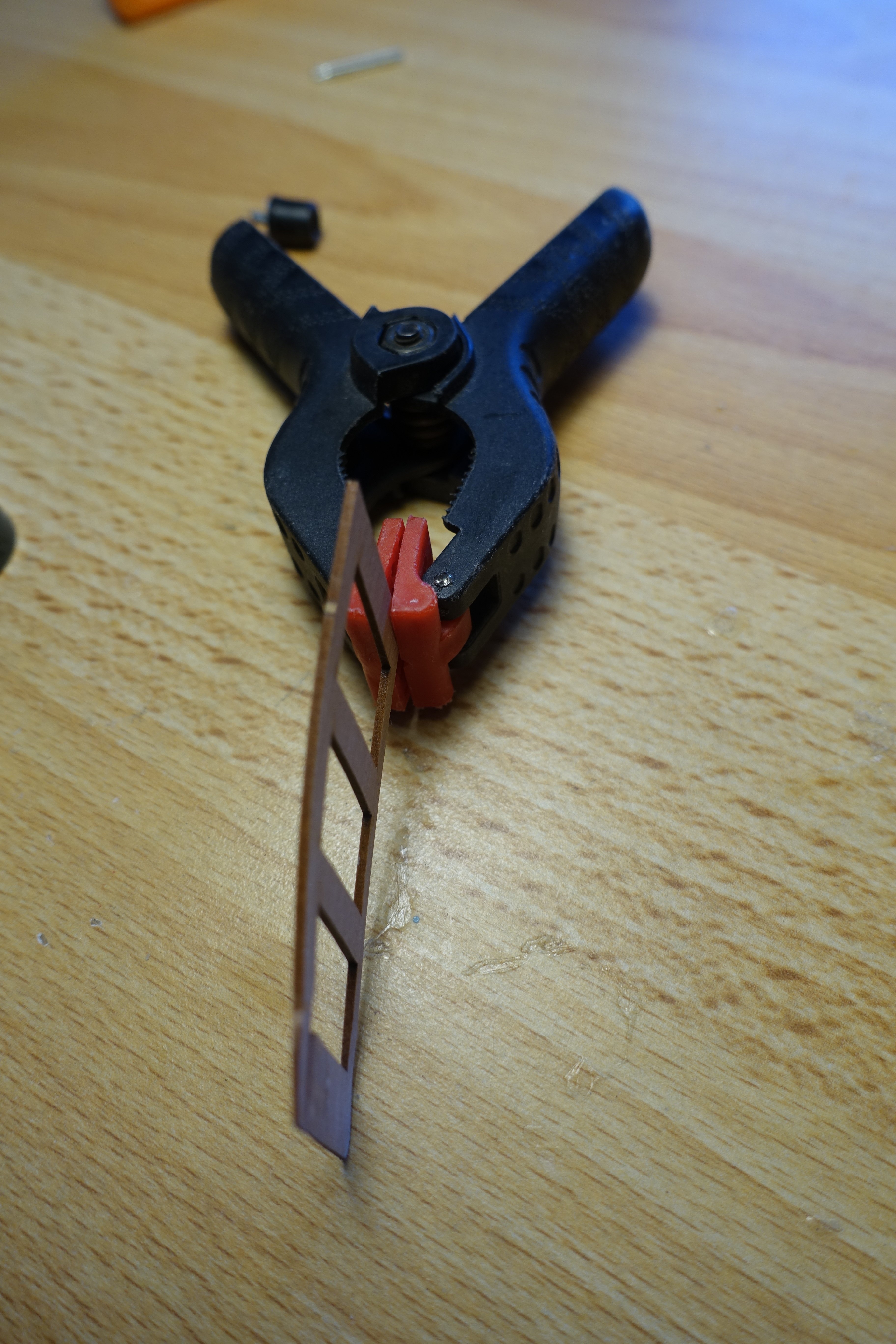
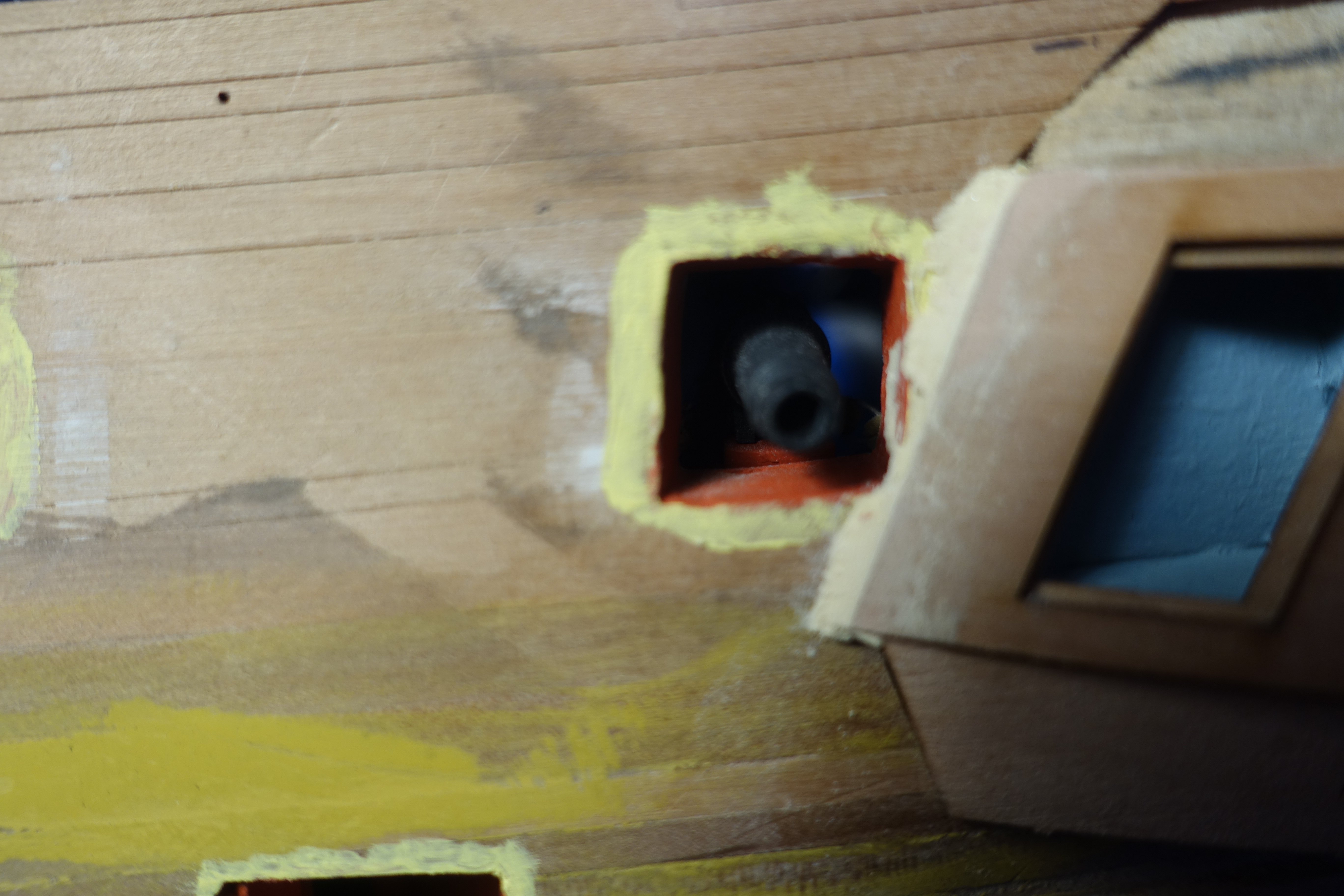
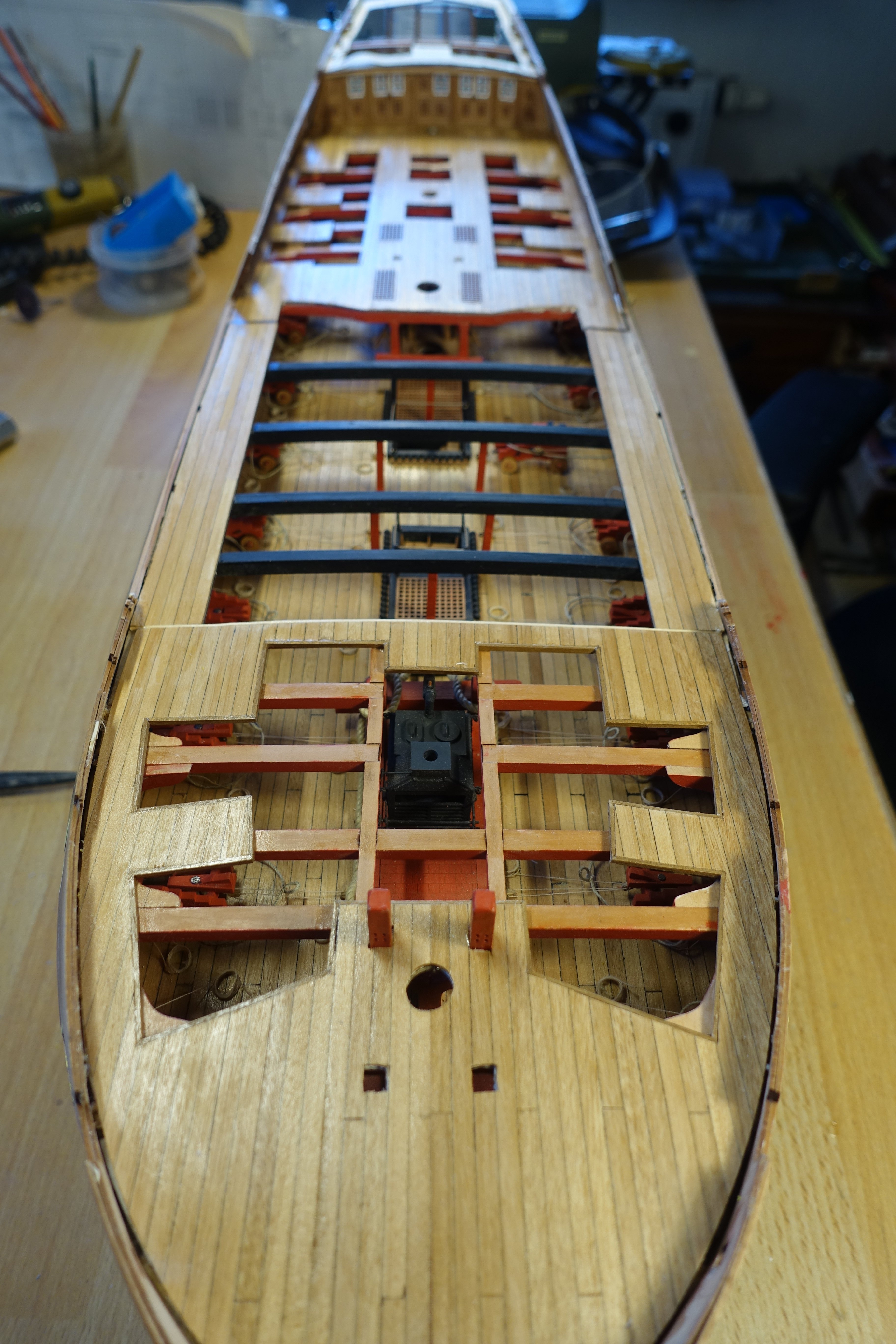
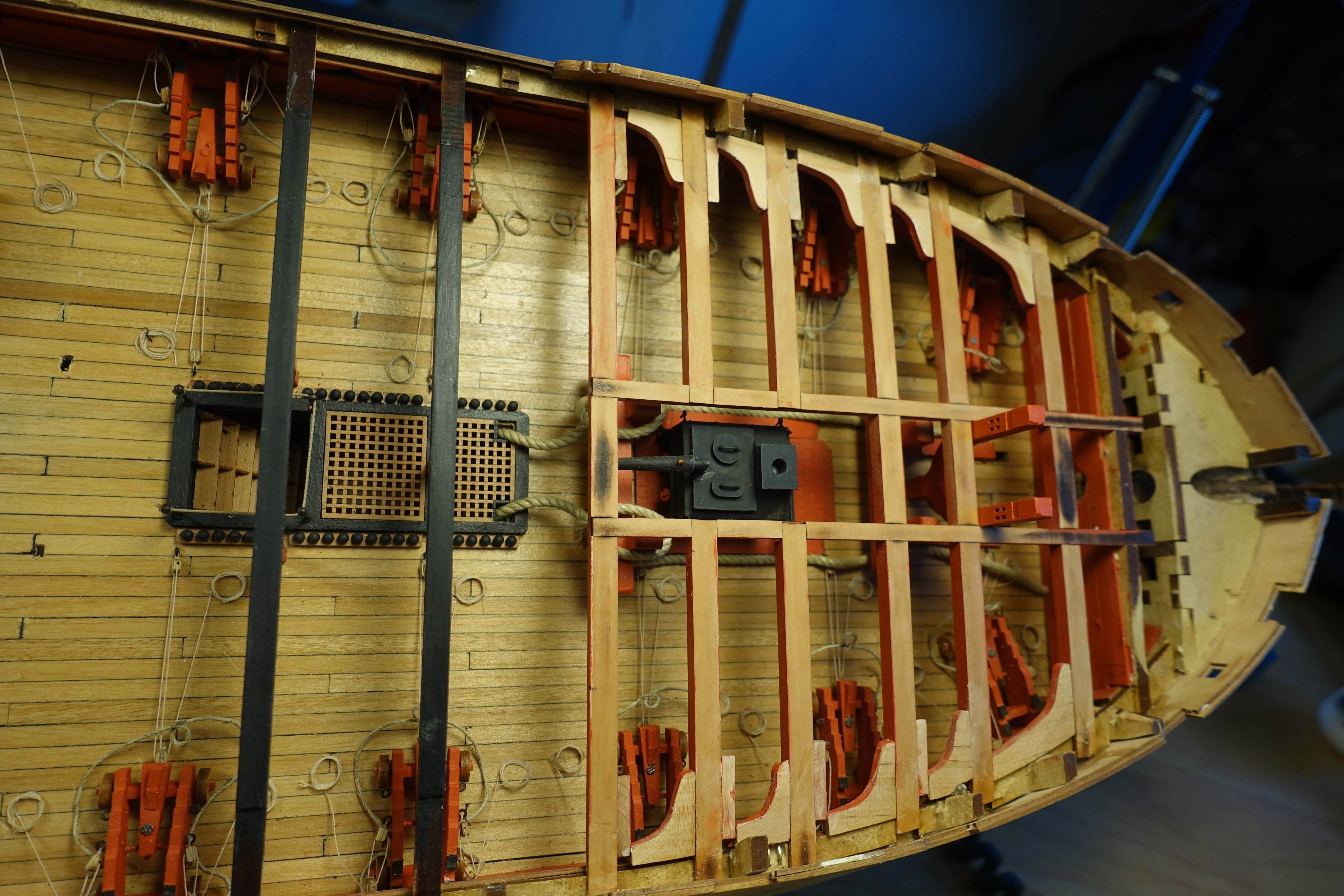
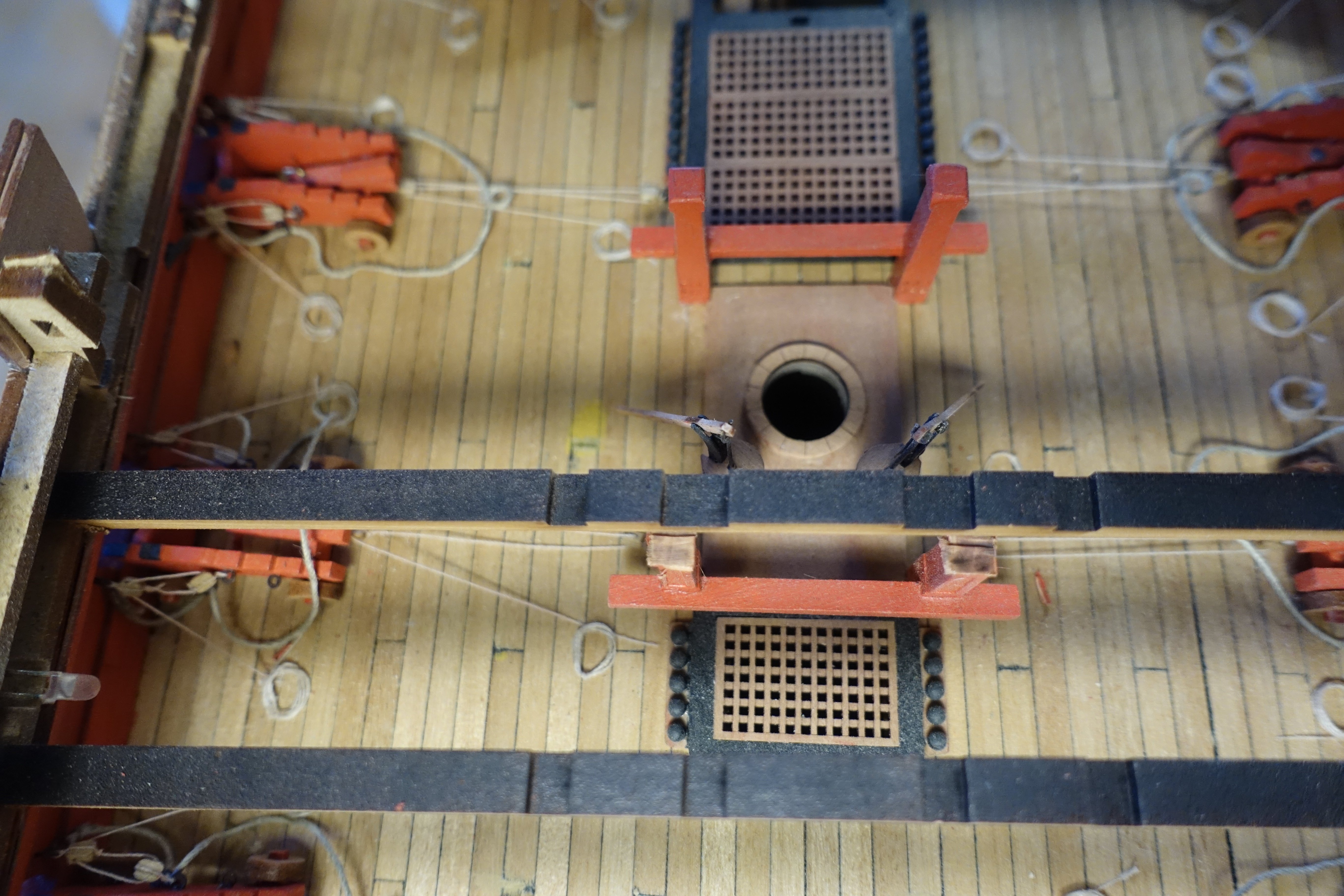
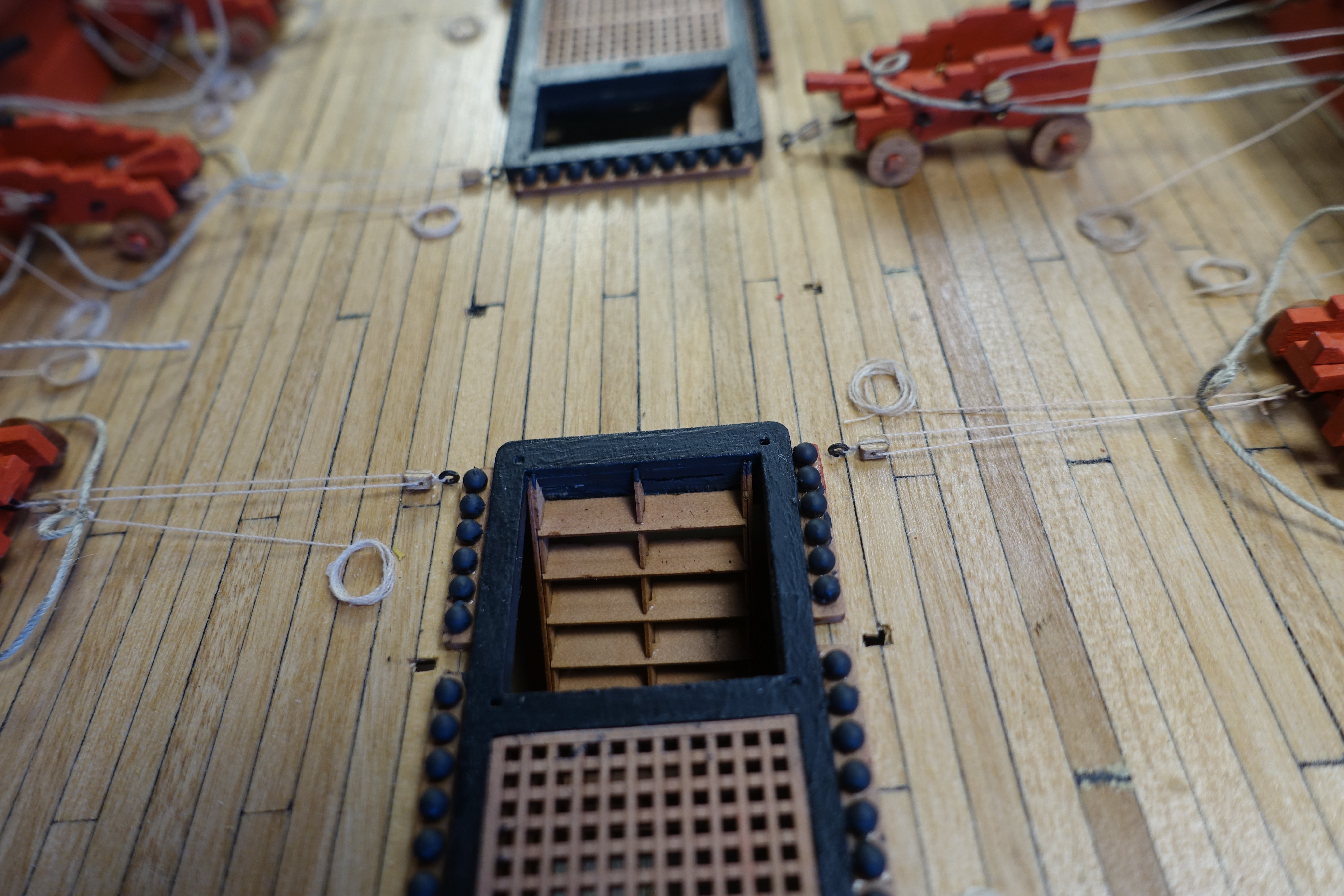
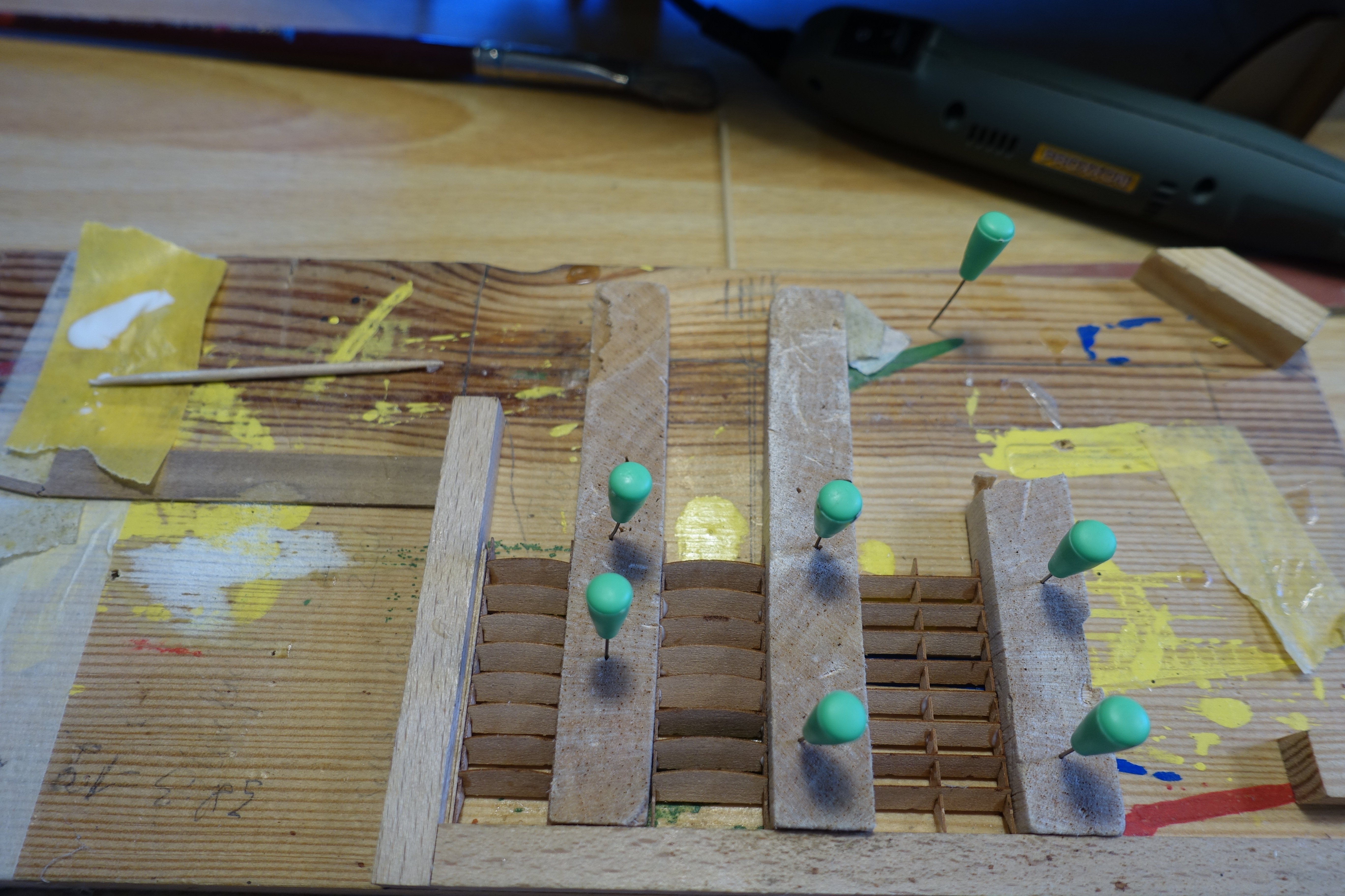
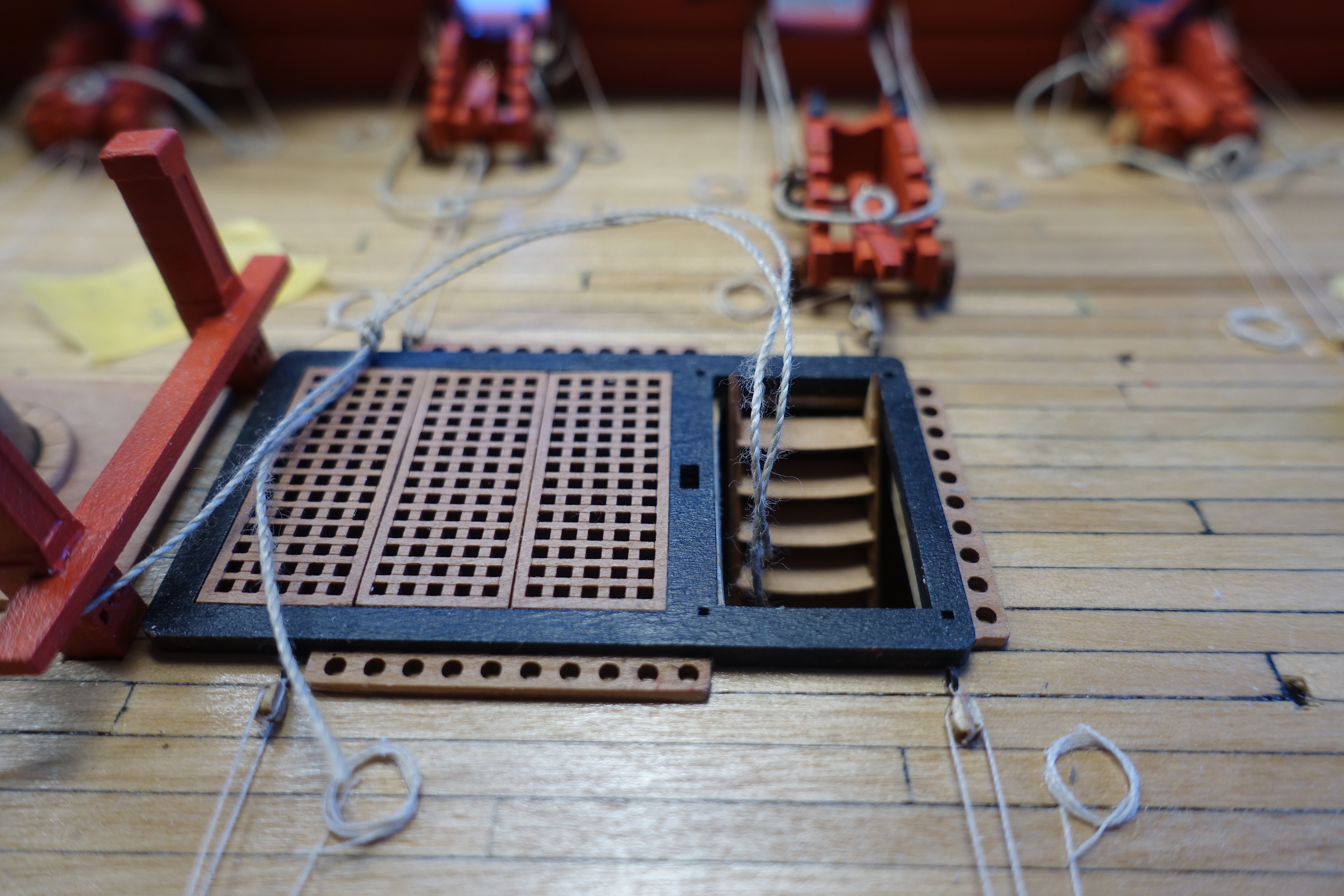
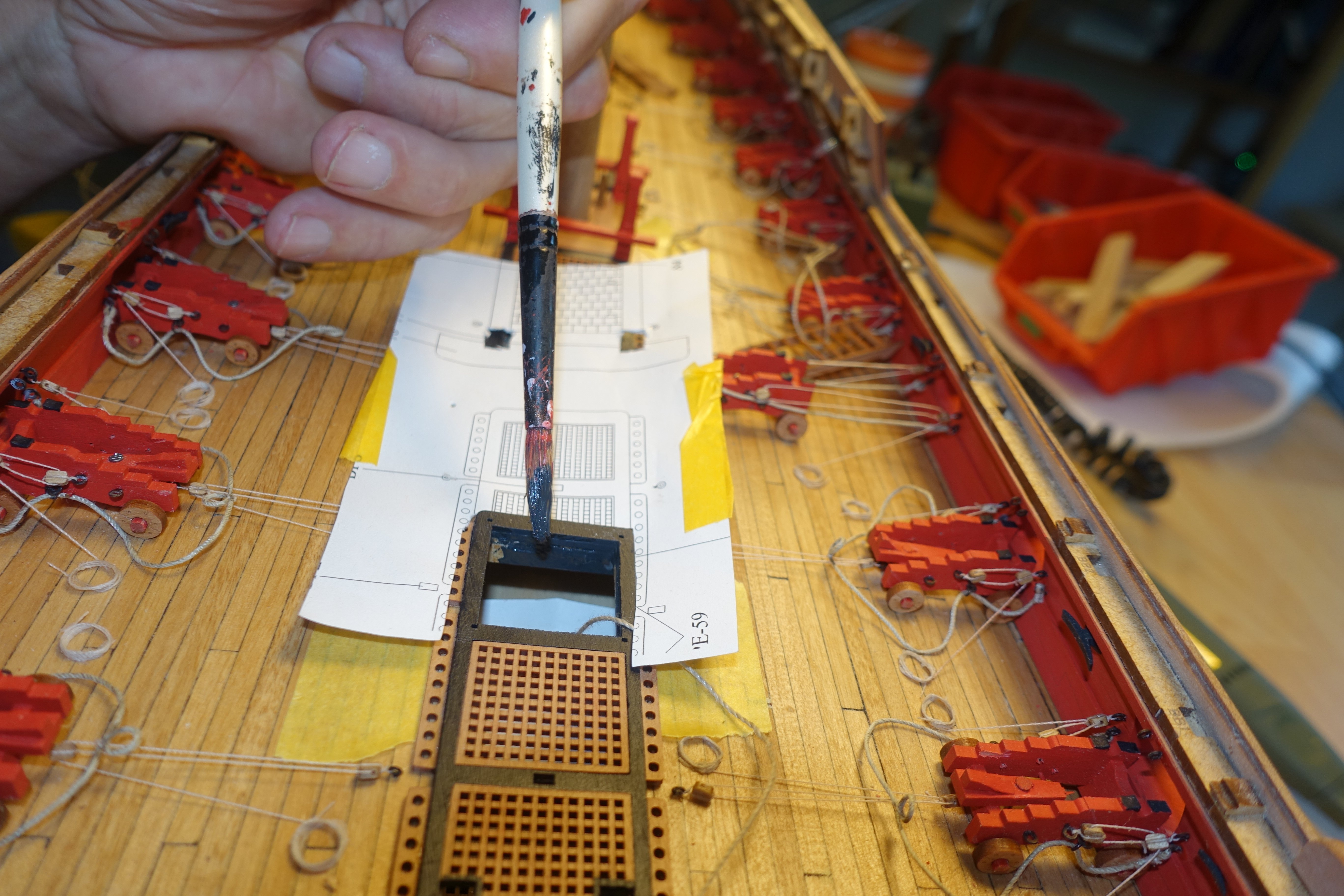
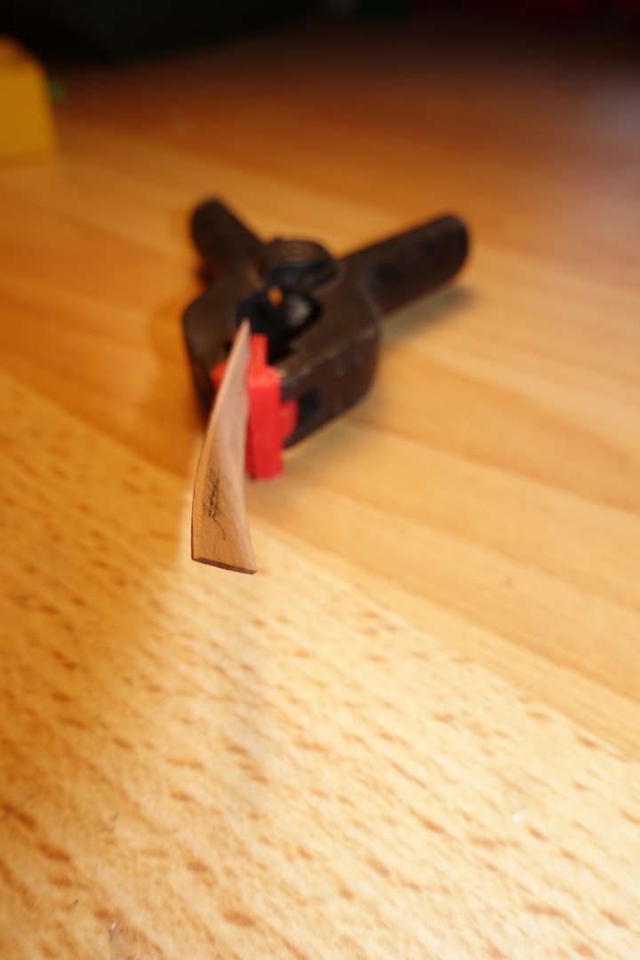
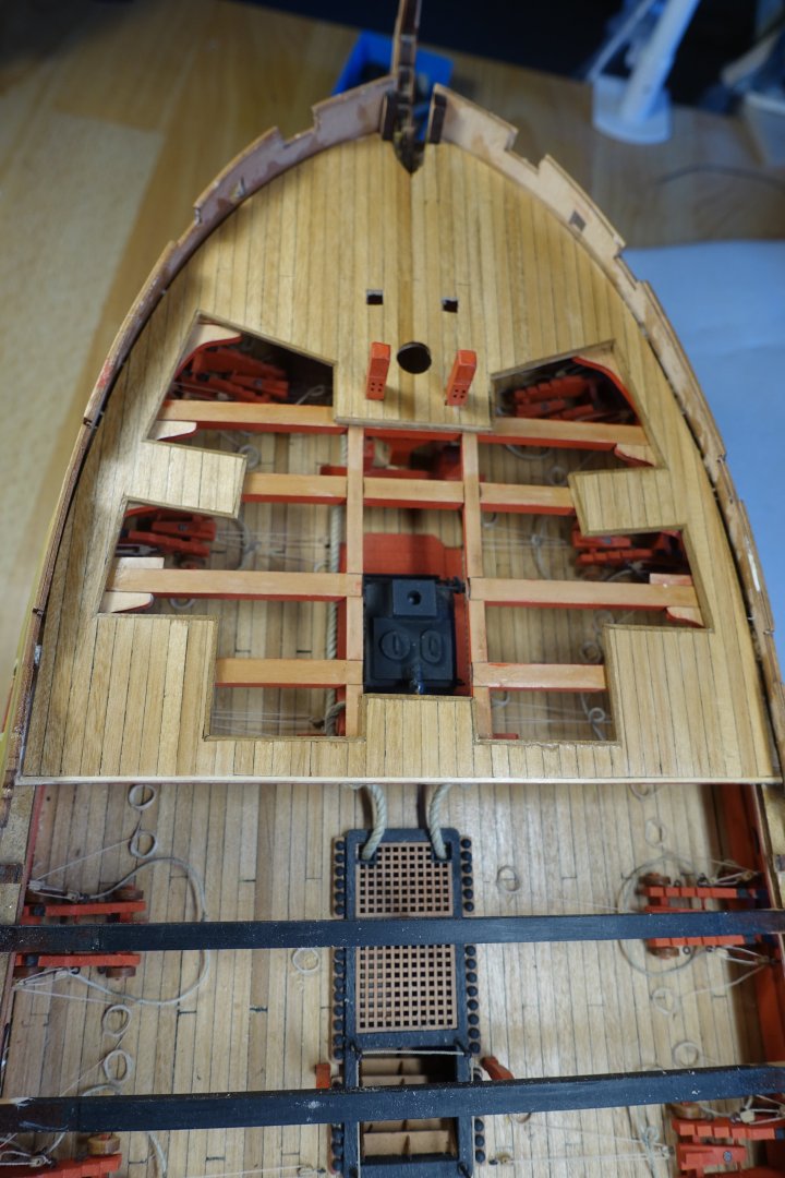
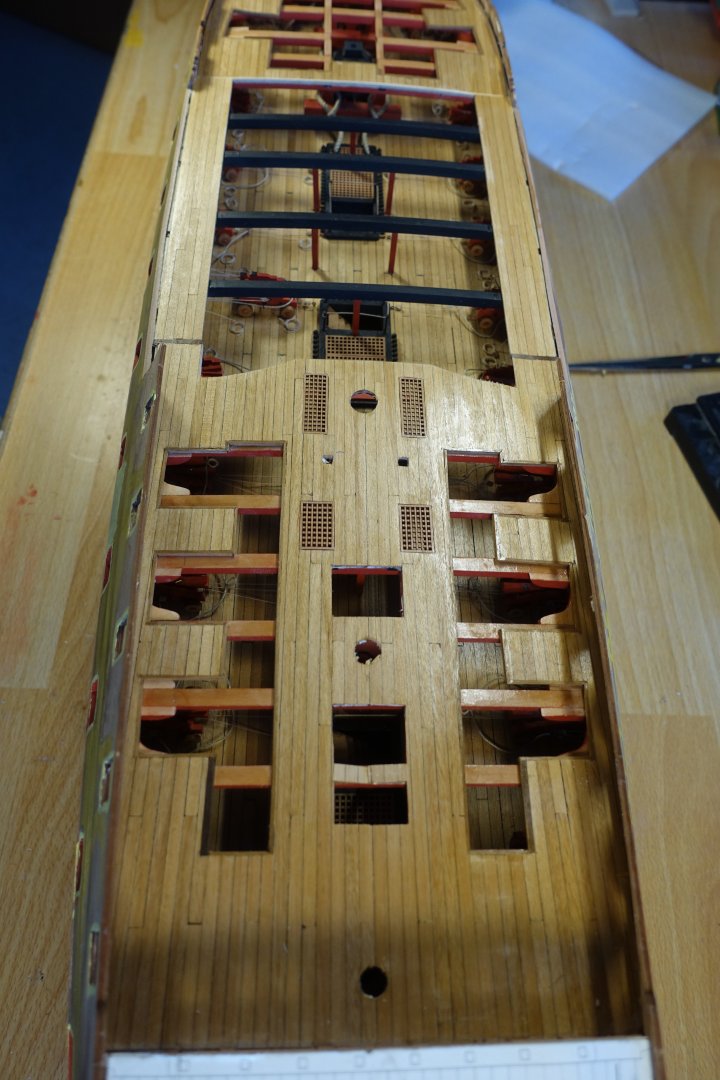
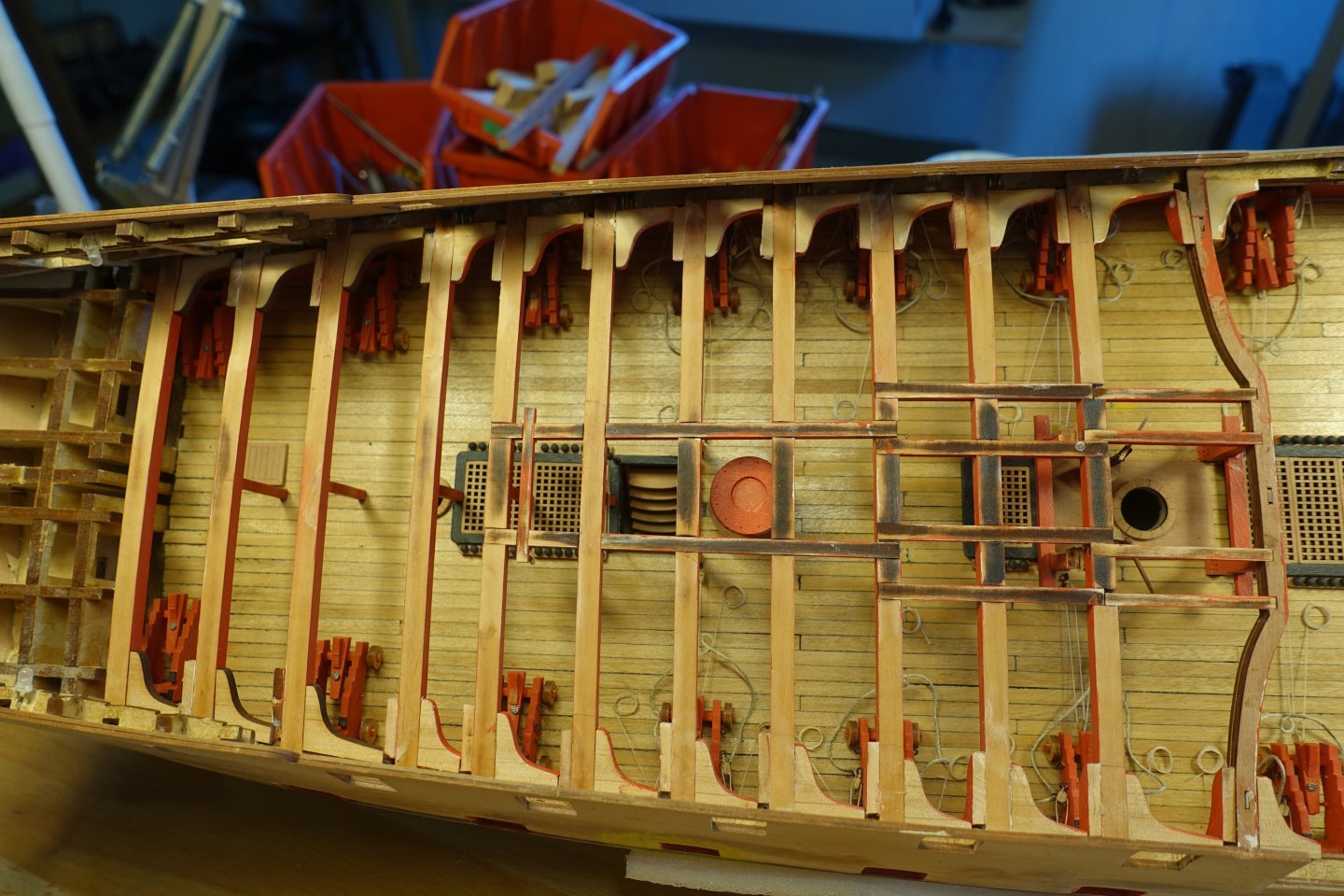
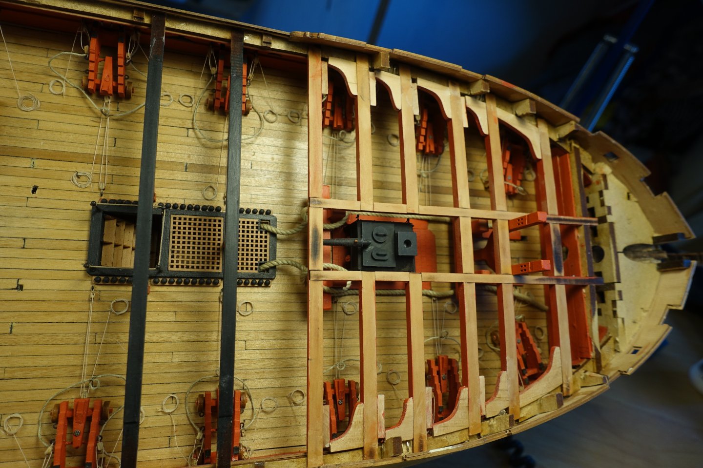
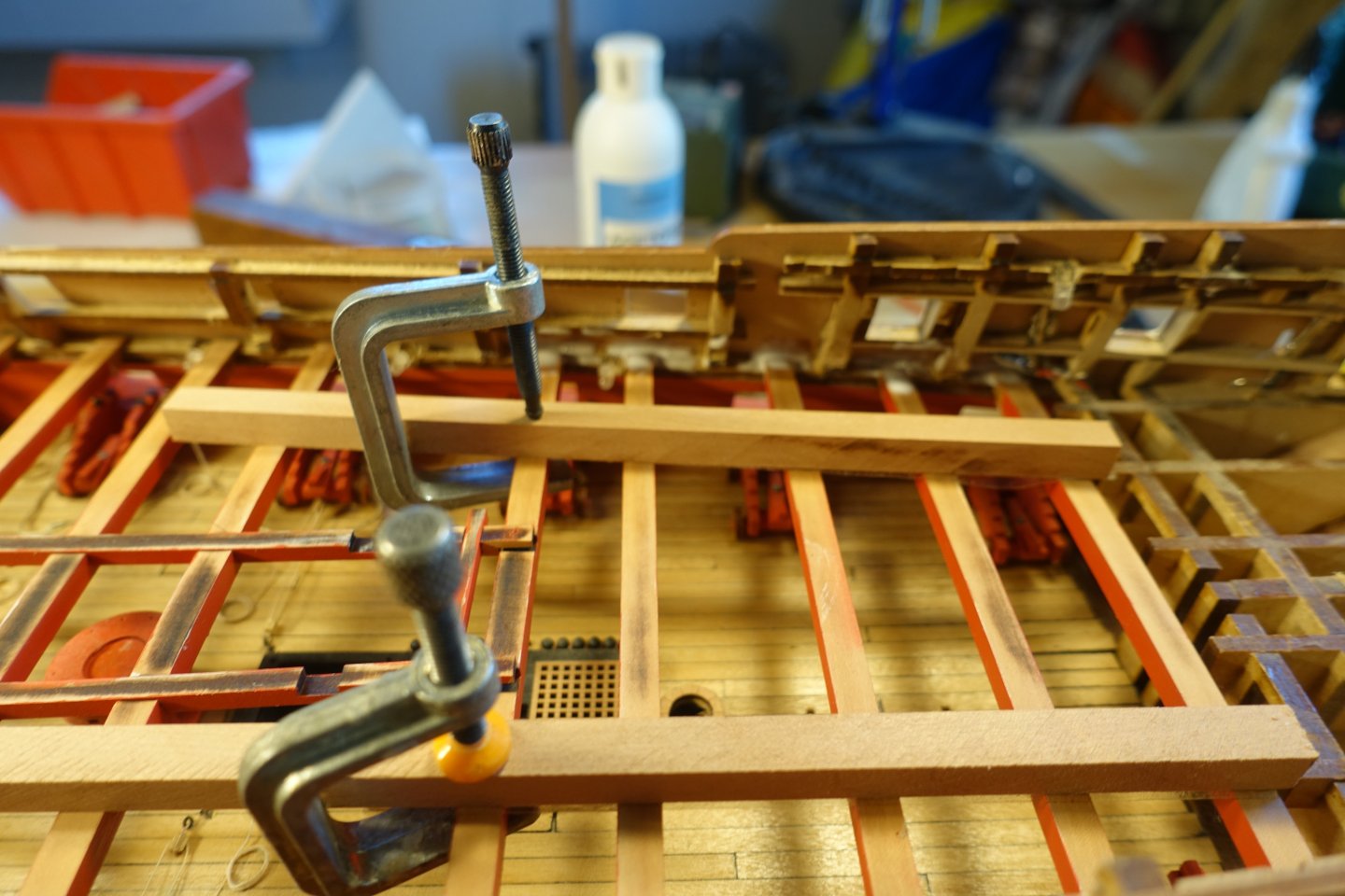
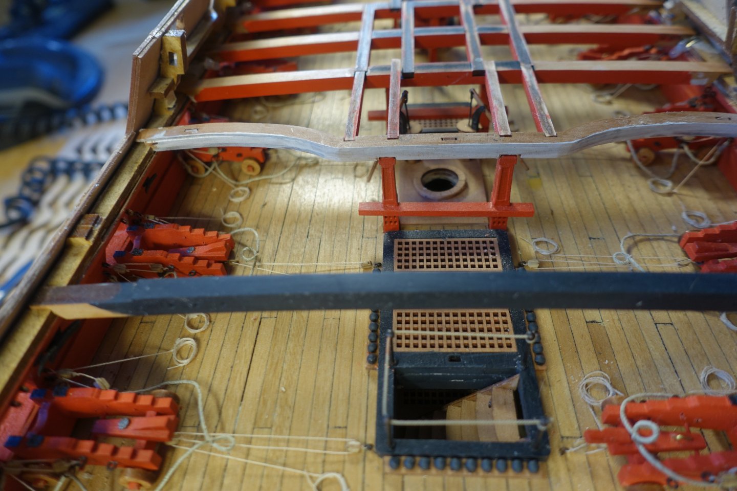
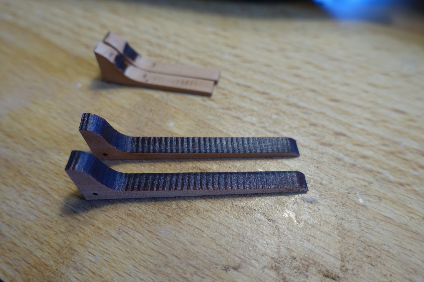
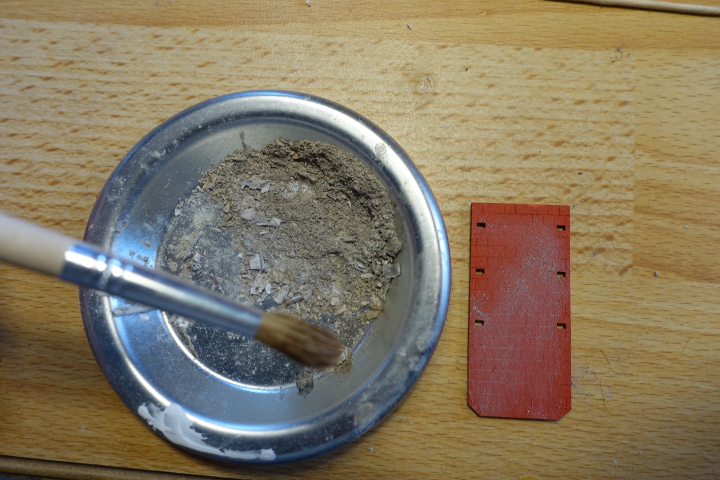
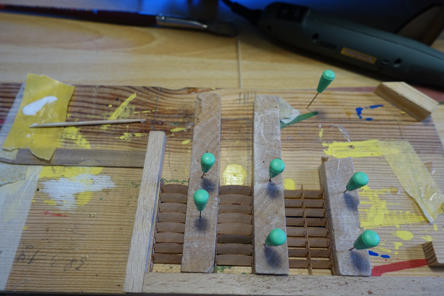
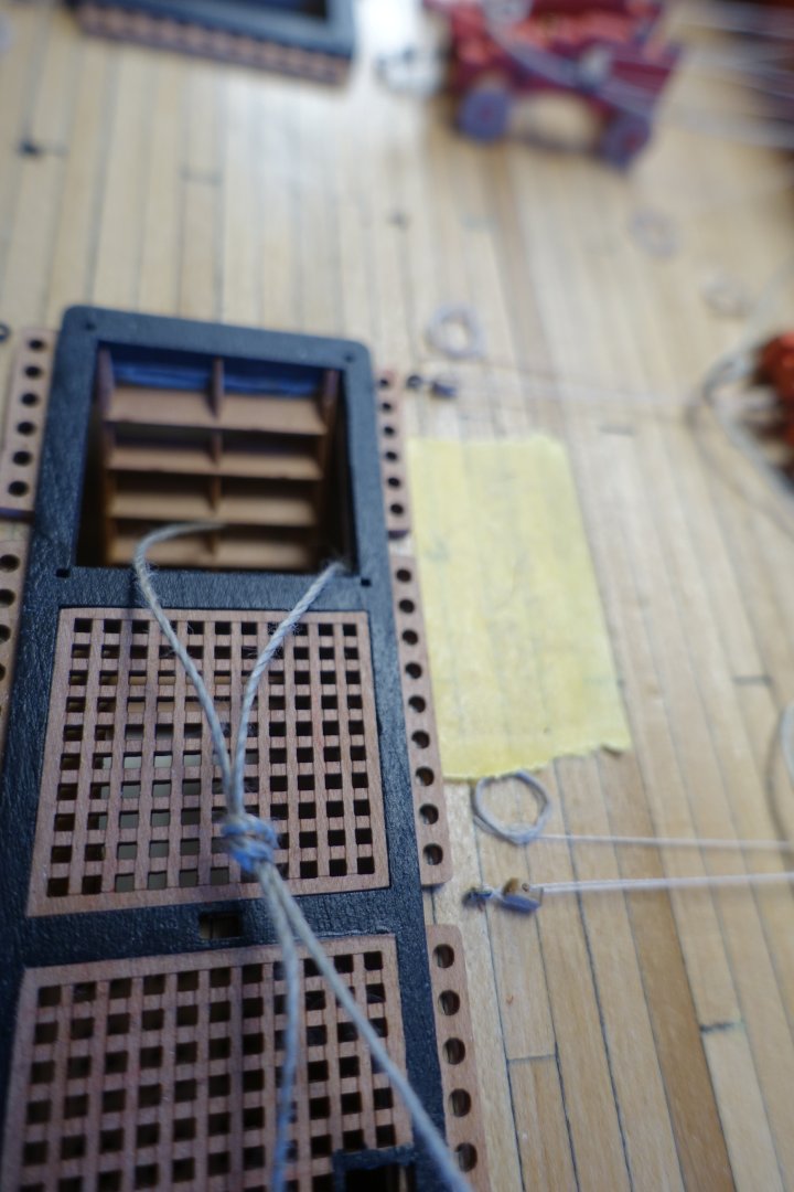
Superstructures Gun deck The laser apparently had some problems with the knees for the bitts; the laser-cut upper surface was quite wavy. However, this was easy to sand smooth. 5734 The knees were then adjusted to fit the deck and bitts. After painting, the hatches and gratings were coated with varnish. I then decided to hide the anchor ropes in the fore gratings. It seemed illogical to me to have them run further across the deck, as they would then conflict with the subsequent superstructures. A corresponding opening was cut into the fore gratings and the edges were painted. After painting, the brick floor for the stove was coated with finely ground real ash and then with varnish. The superstructures were attached. My wooden right angle was used again to glue the ladders together. The ladders were adjusted on a trial basis. The thread on the ladders helps to retrieve them when they disappear into the lower deck. The openings of the companionways were painted black. I was bothered by the fact that the substructure was visible. Here, the thread leads to a piece of paper that I placed on the lower deck. The stove, the pumps and the ladders still need to be added. I will attach the railing supports for the companionways later. I'm afraid they will bend.


-
Hi B.E., Thank you for your reply. So I will run the anchor rope further towards the stern and then lead it down through the gratings. I'm not sure about the messenger cables yet, whether I should show them, as they are only attached when anchoring, at least I assume so. Thanks again for the tip. Clark
-
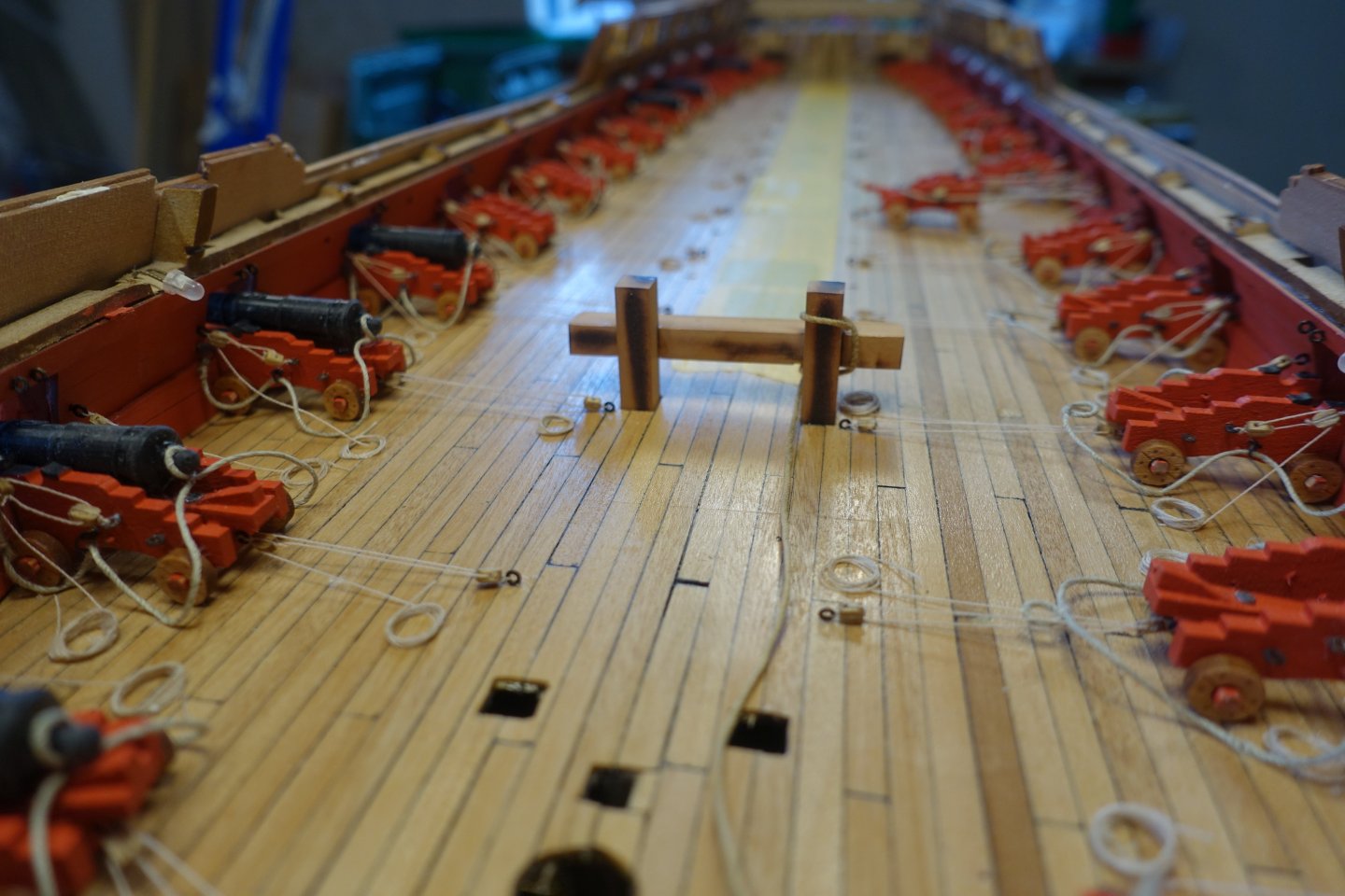
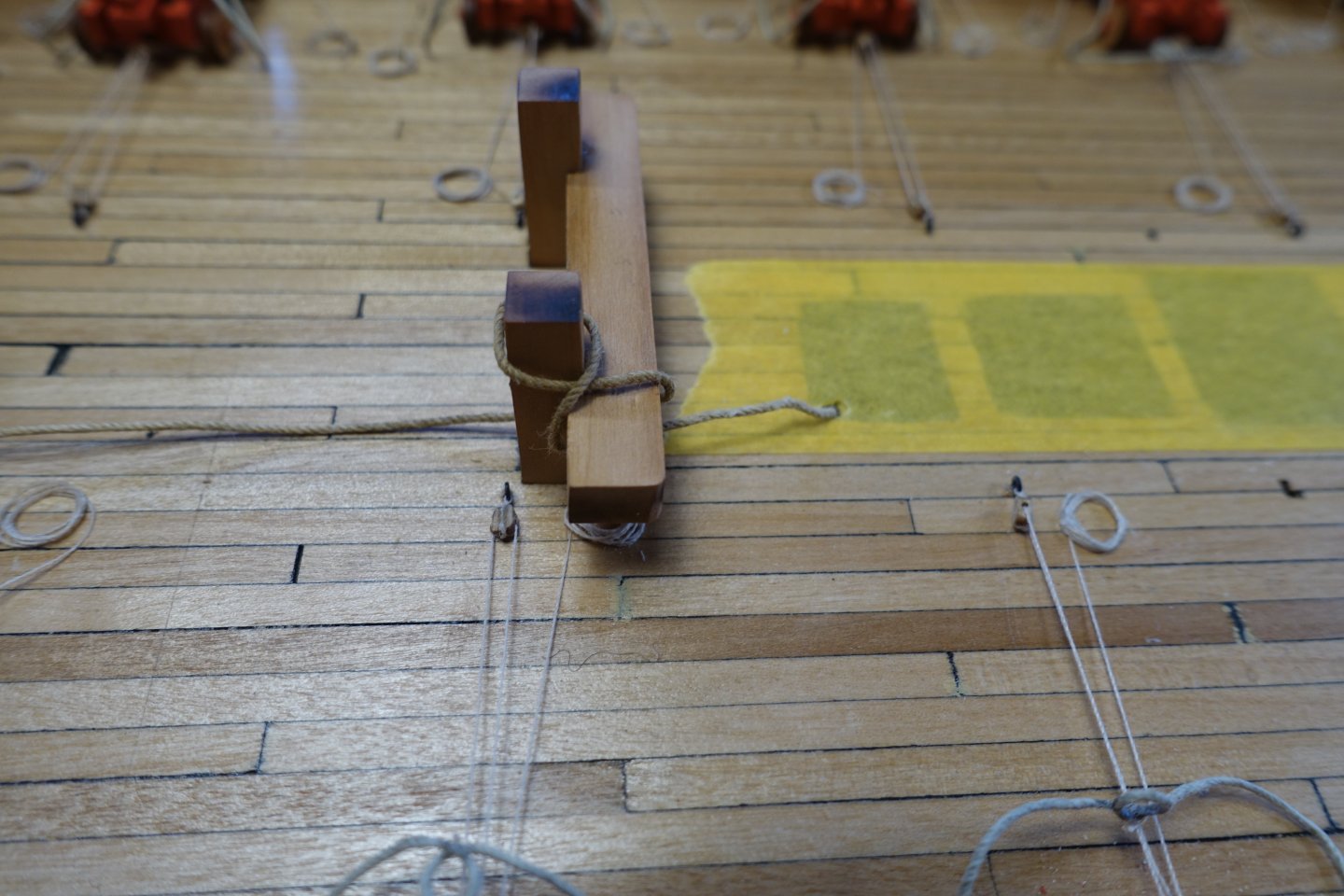
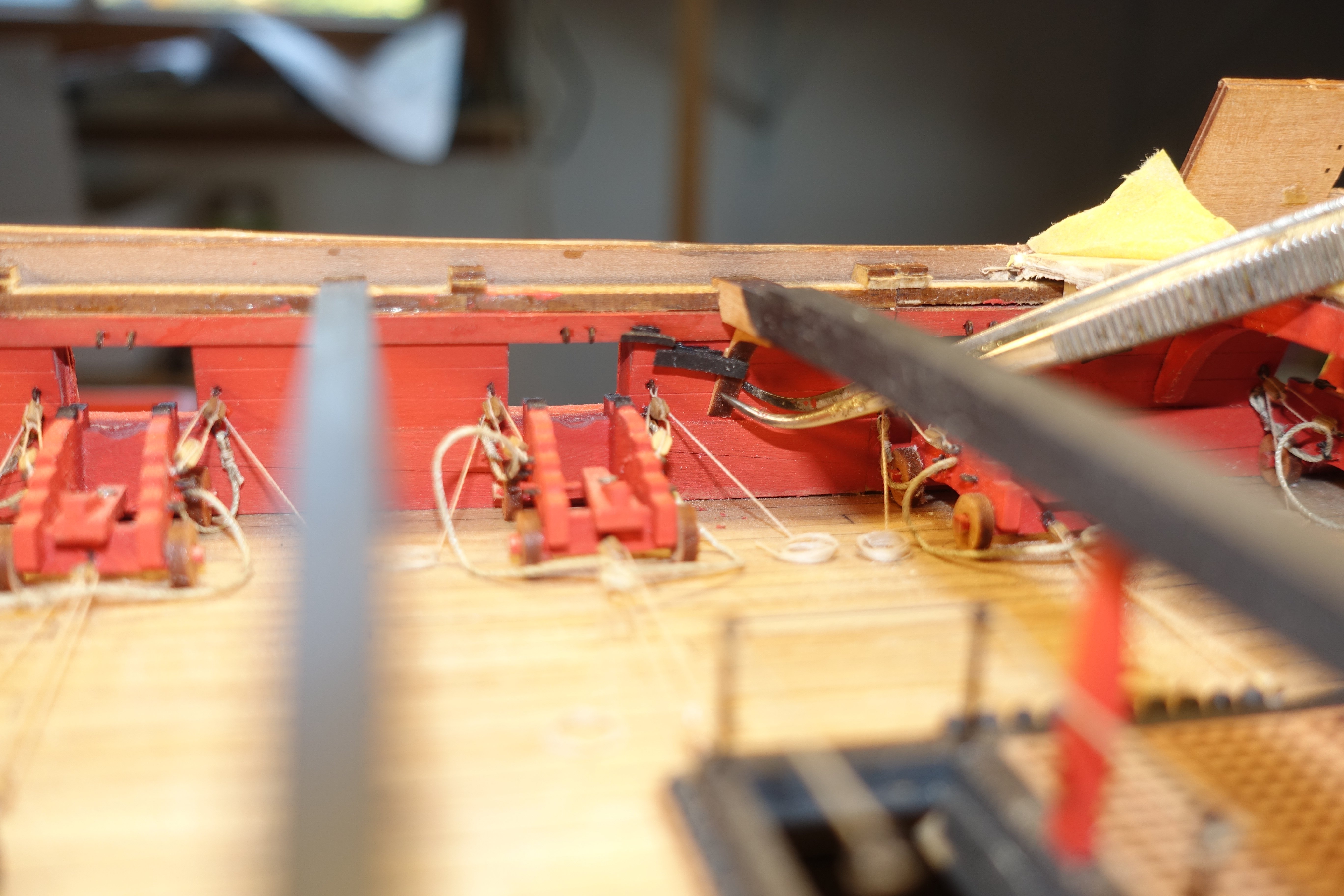
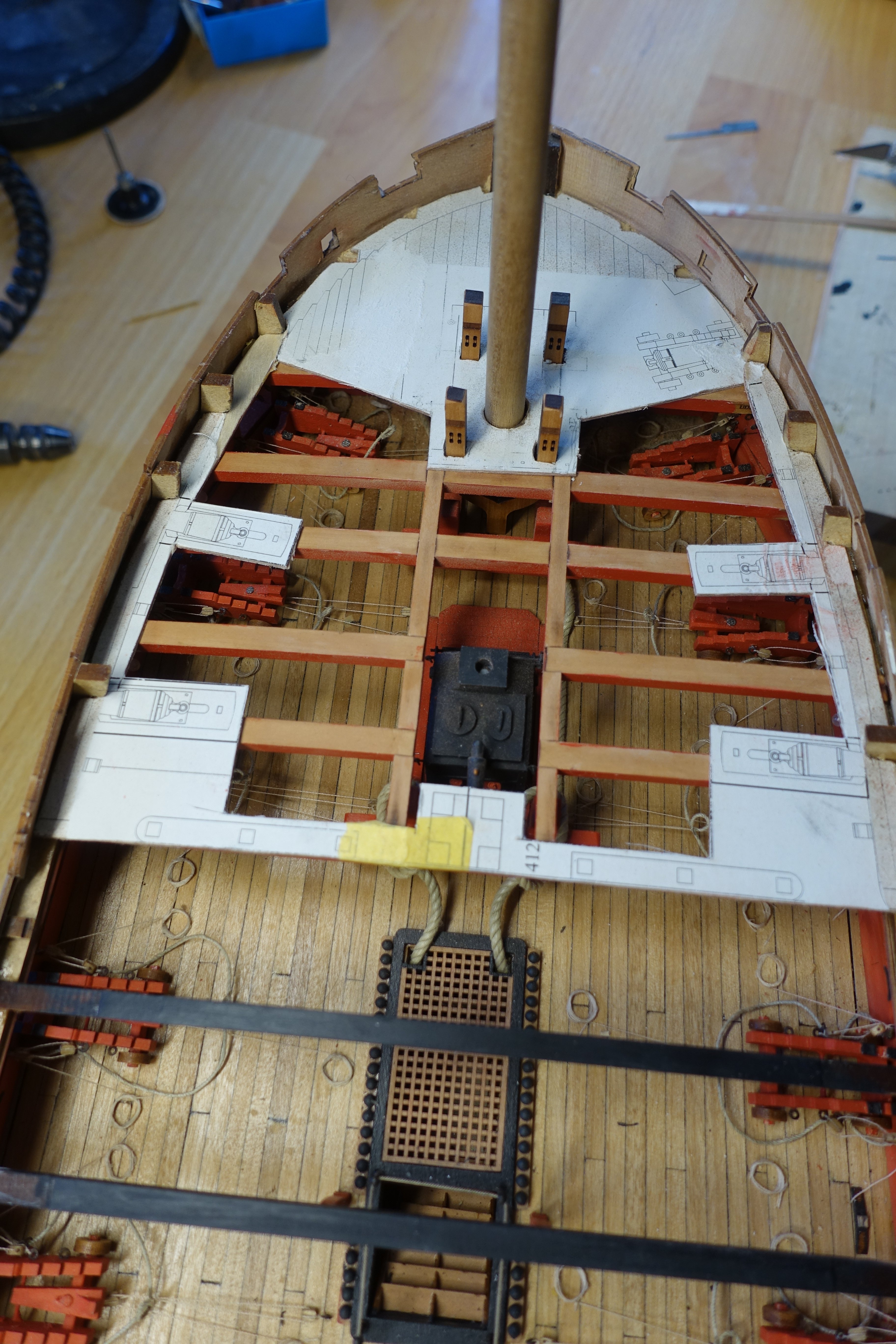
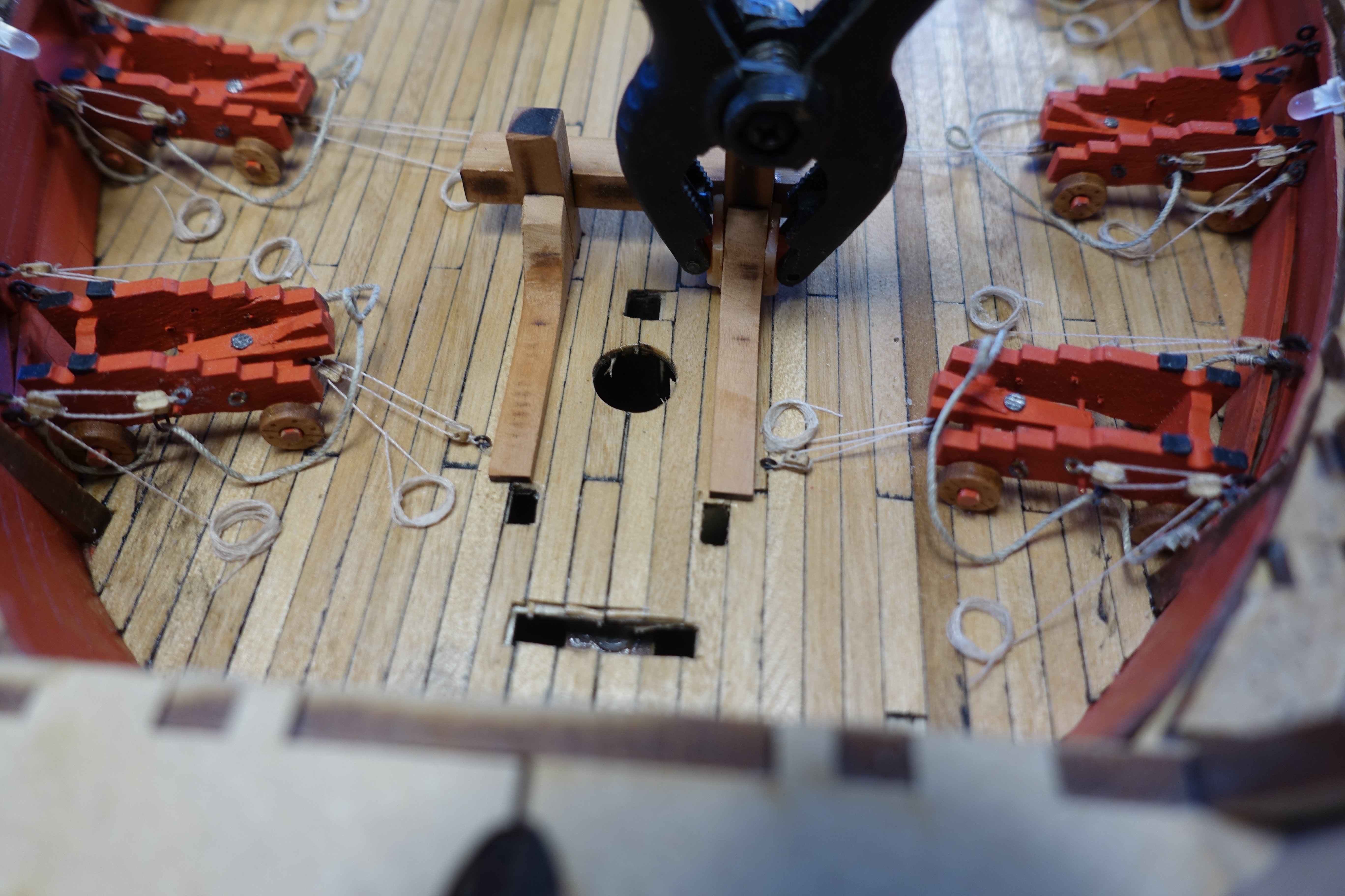
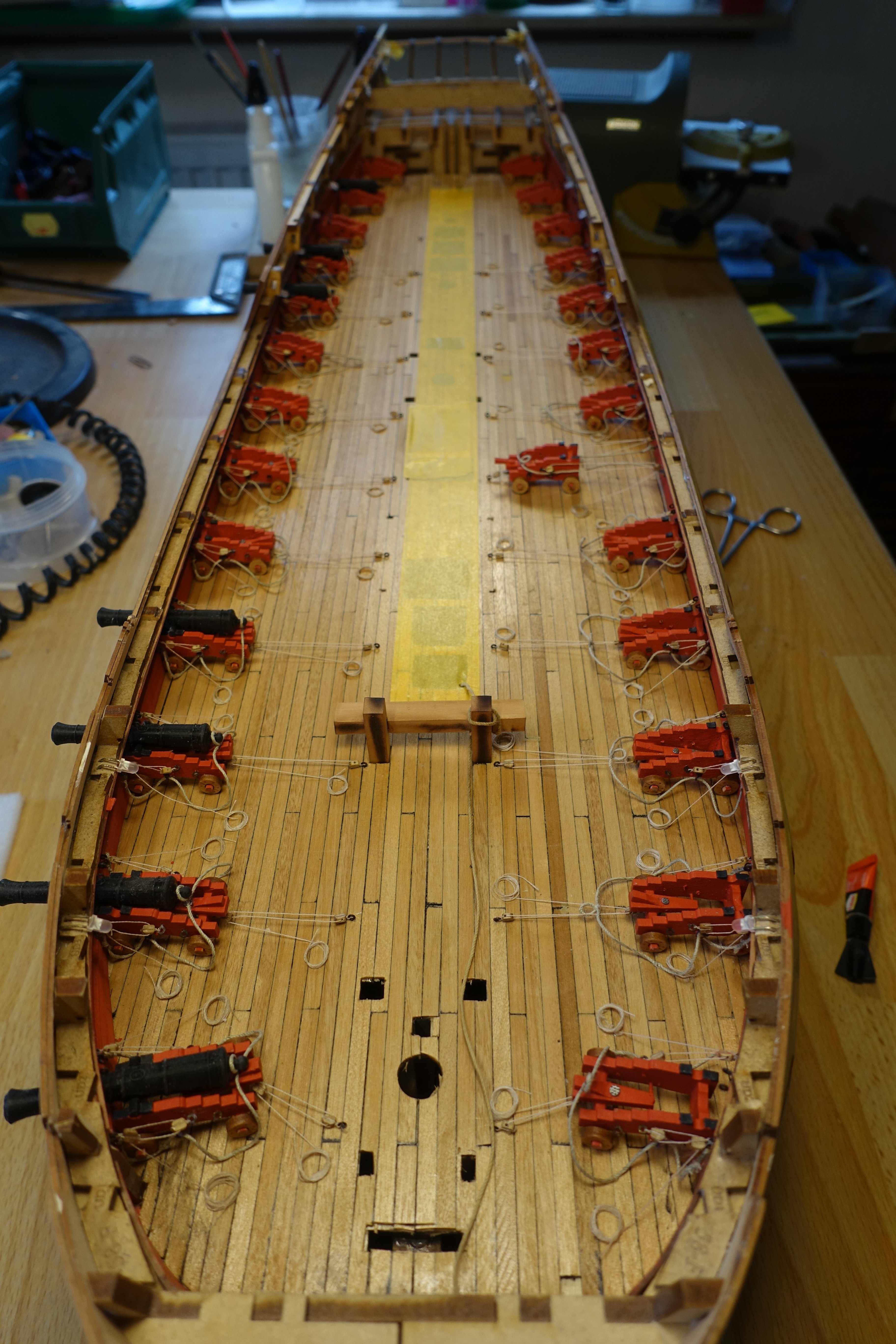
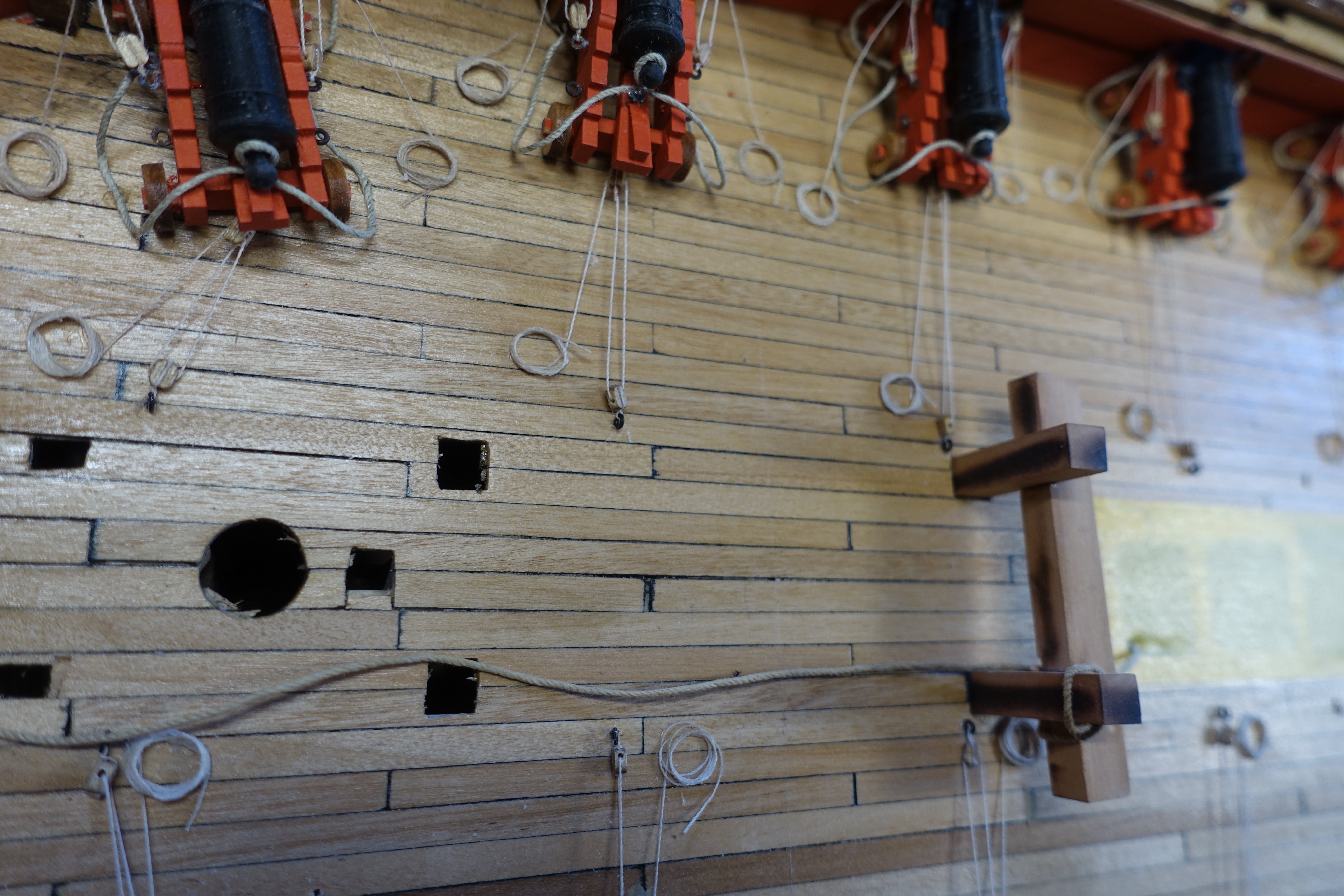
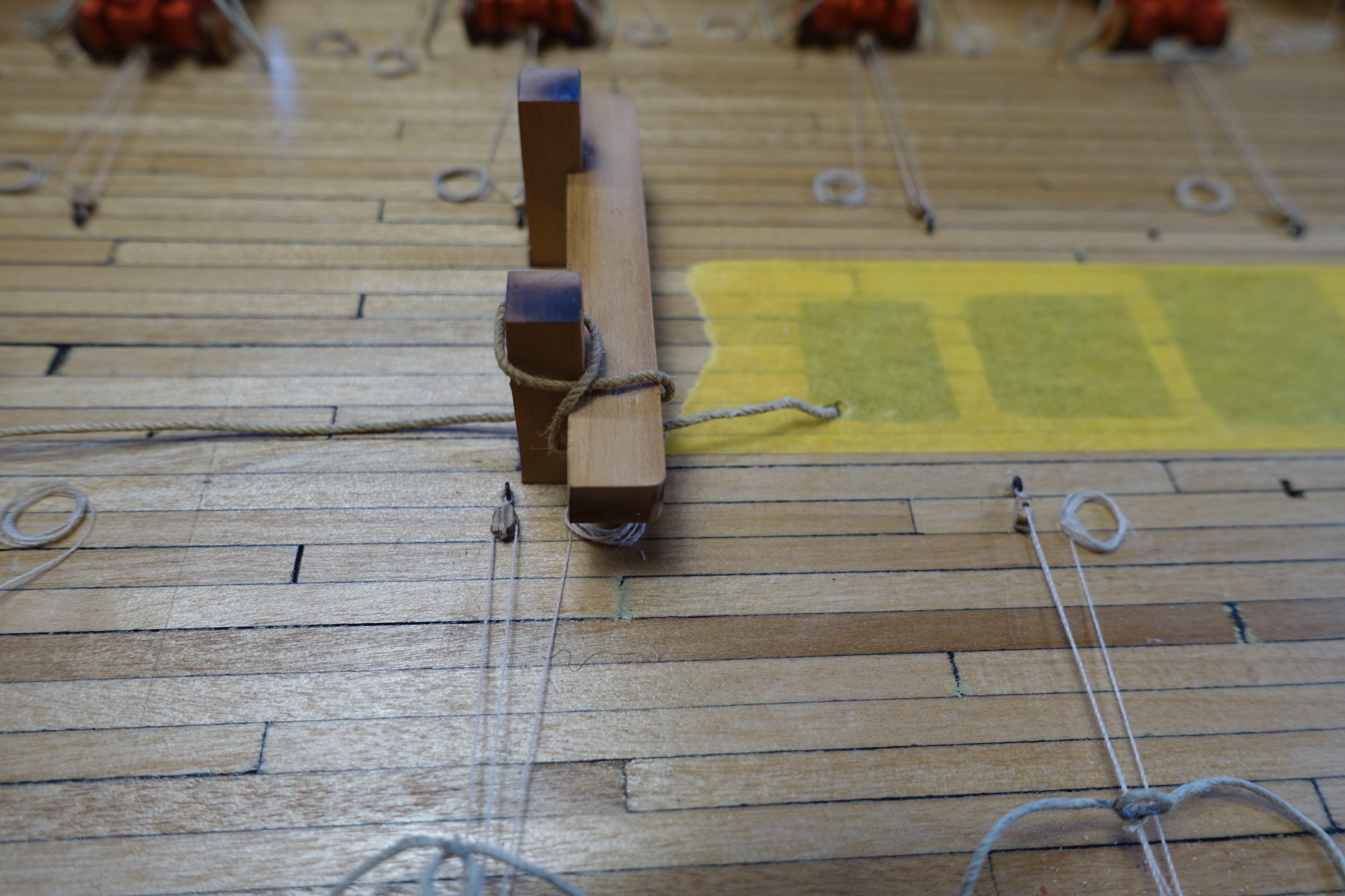
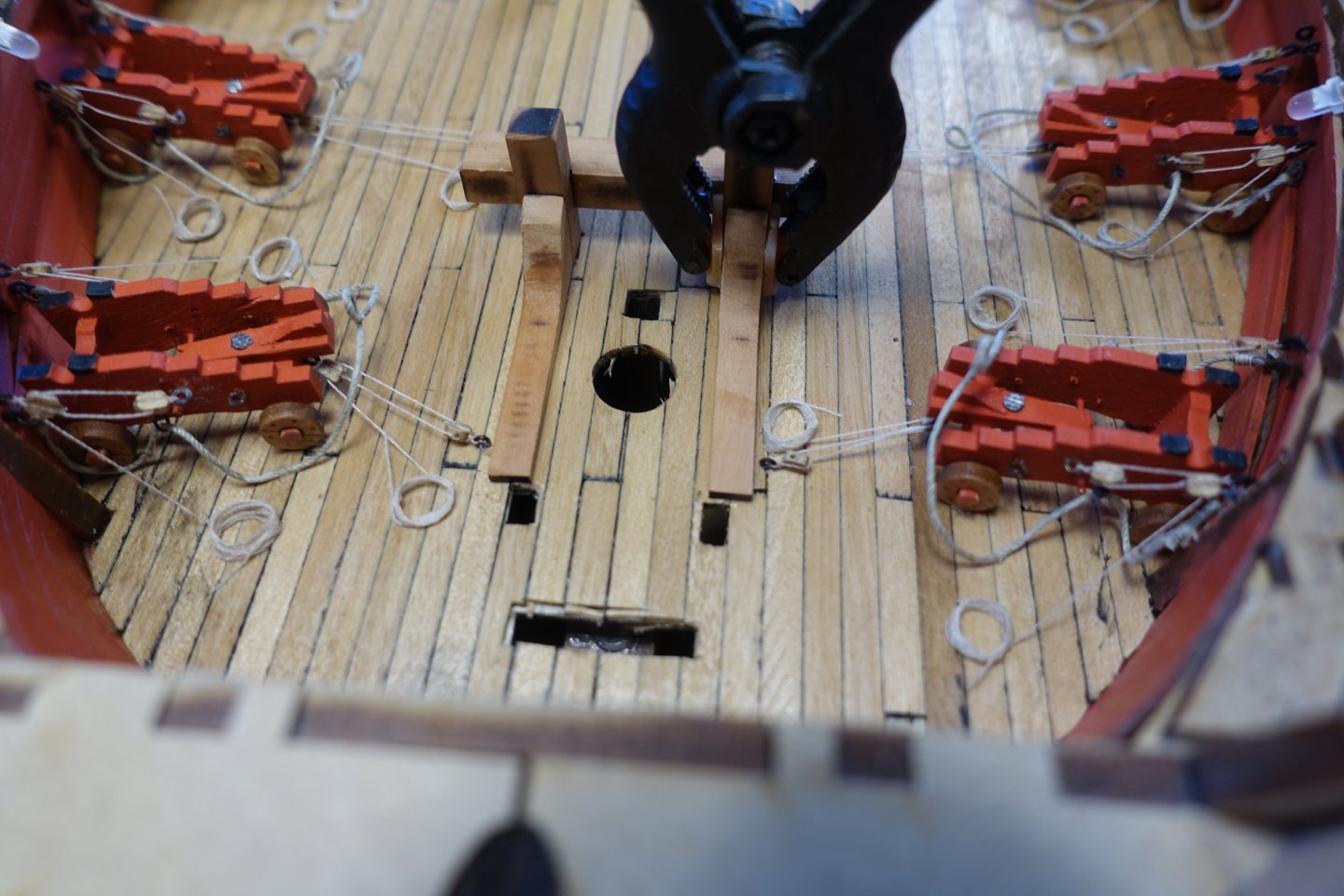
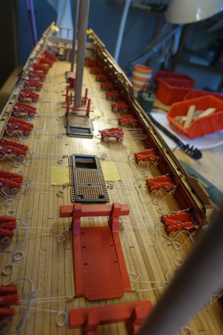
A quick update and a question The cannons are now all rigged except for the last three at the stern, as these will hardly be visible. However, I have been thinking about the course of the anchor ropen. I couldn't find anything about this in the plans or the other reports. I don't think it was stored directly in the bow, so I have come up with a route. Can anyone comment on whether this is plausible? The final anchor rope will be thicker.