Clark
-
Posts
310 -
Joined
-
Last visited
Content Type
Profiles
Forums
Gallery
Events
Everything posted by Clark
-
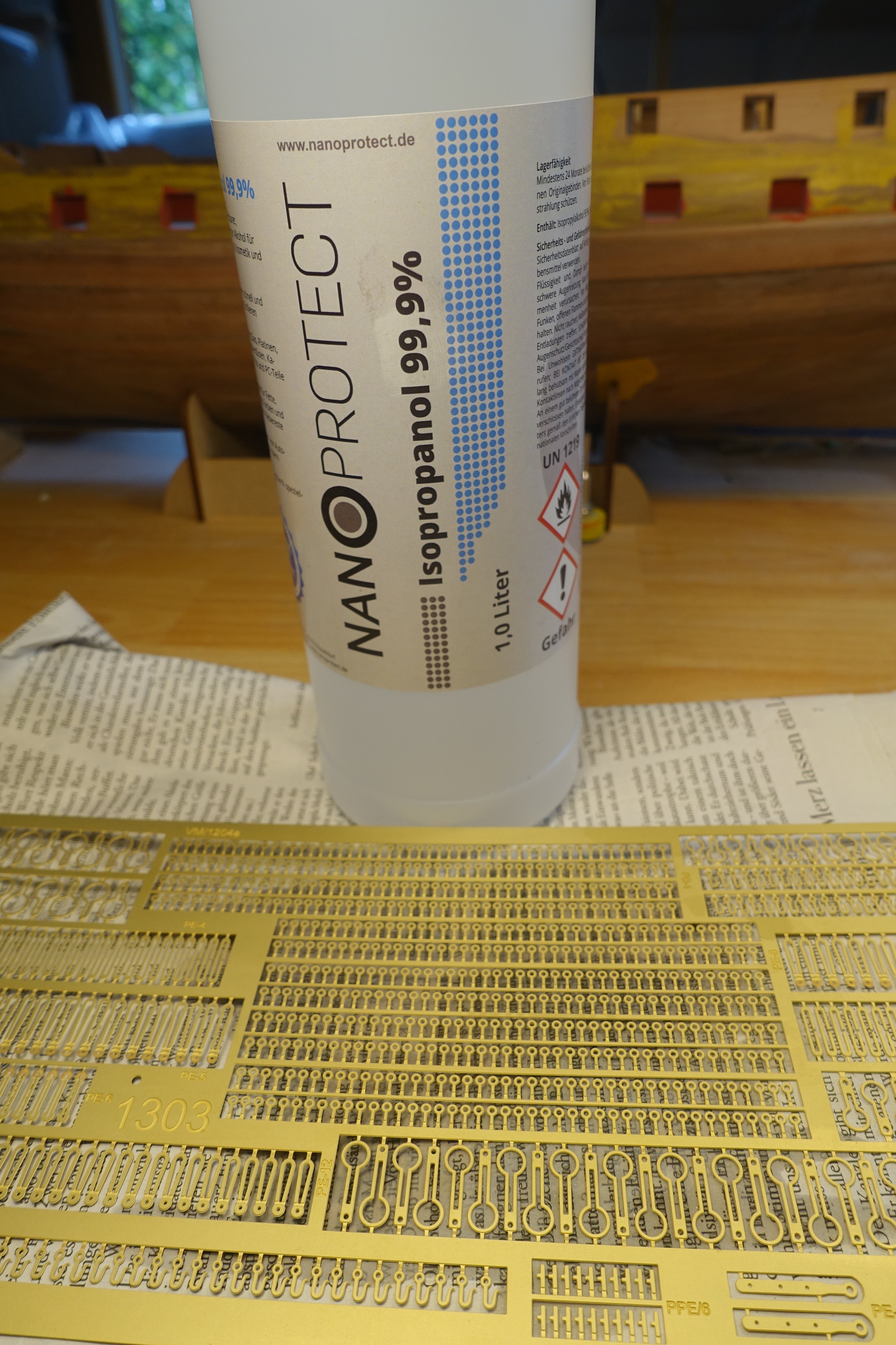
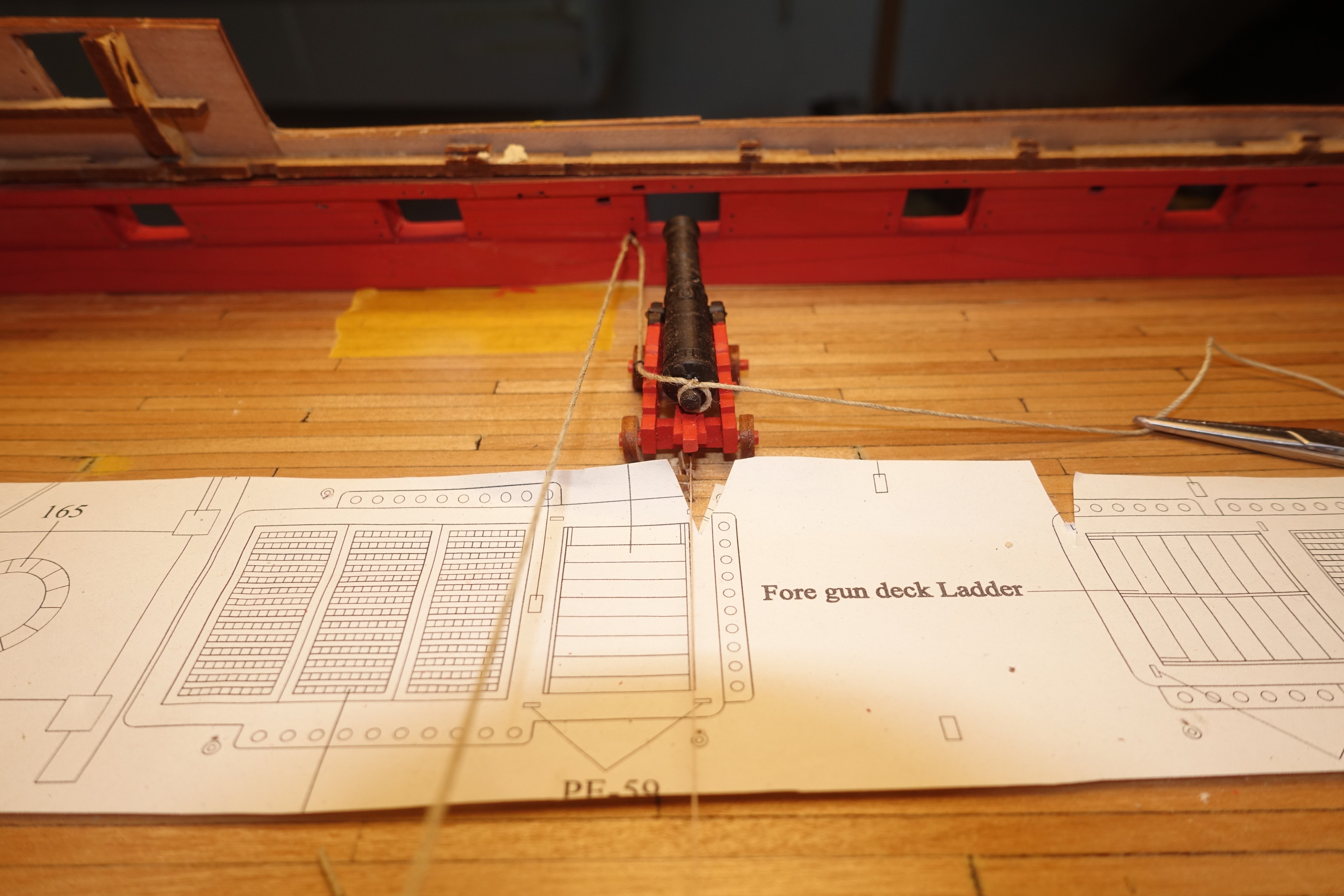
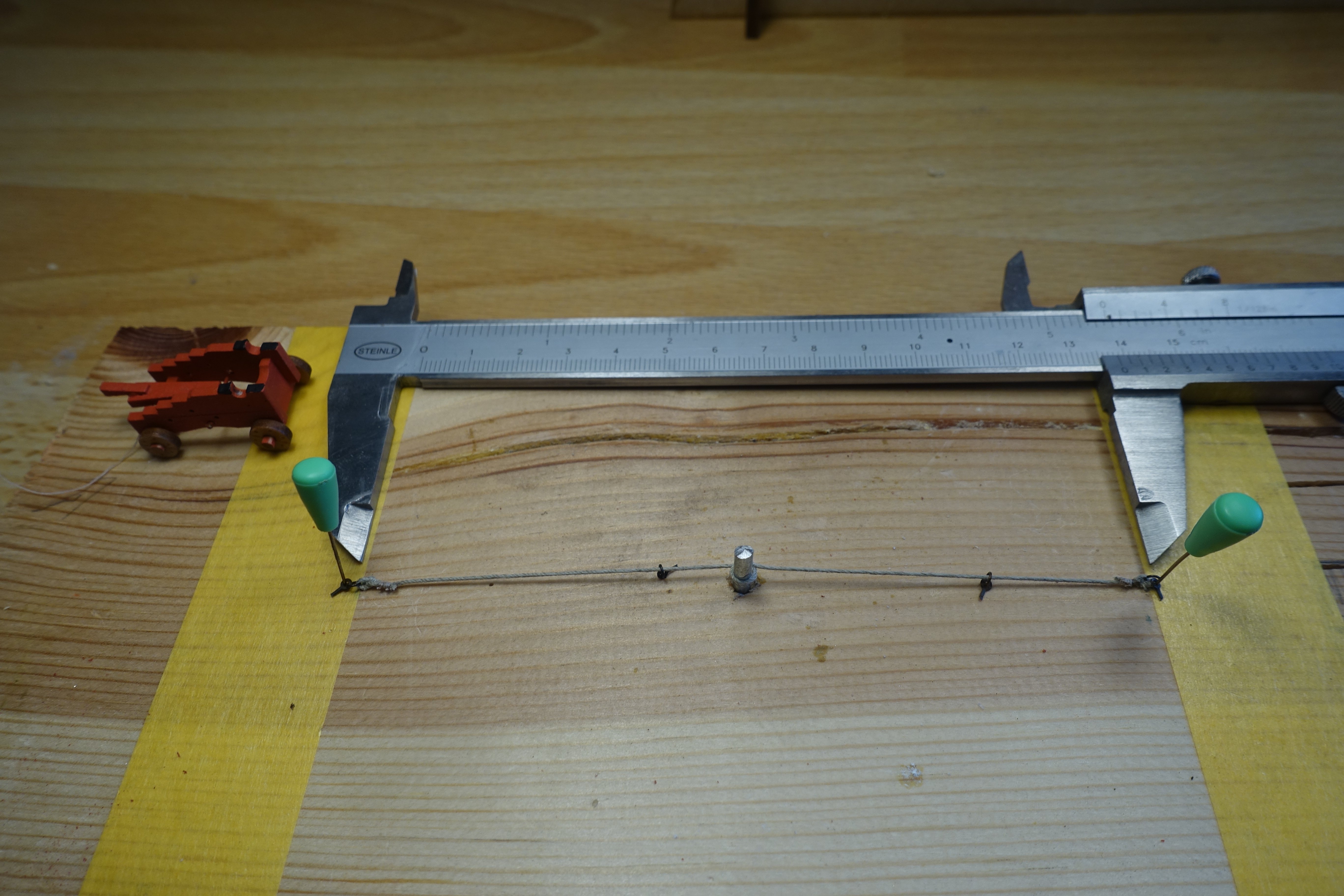
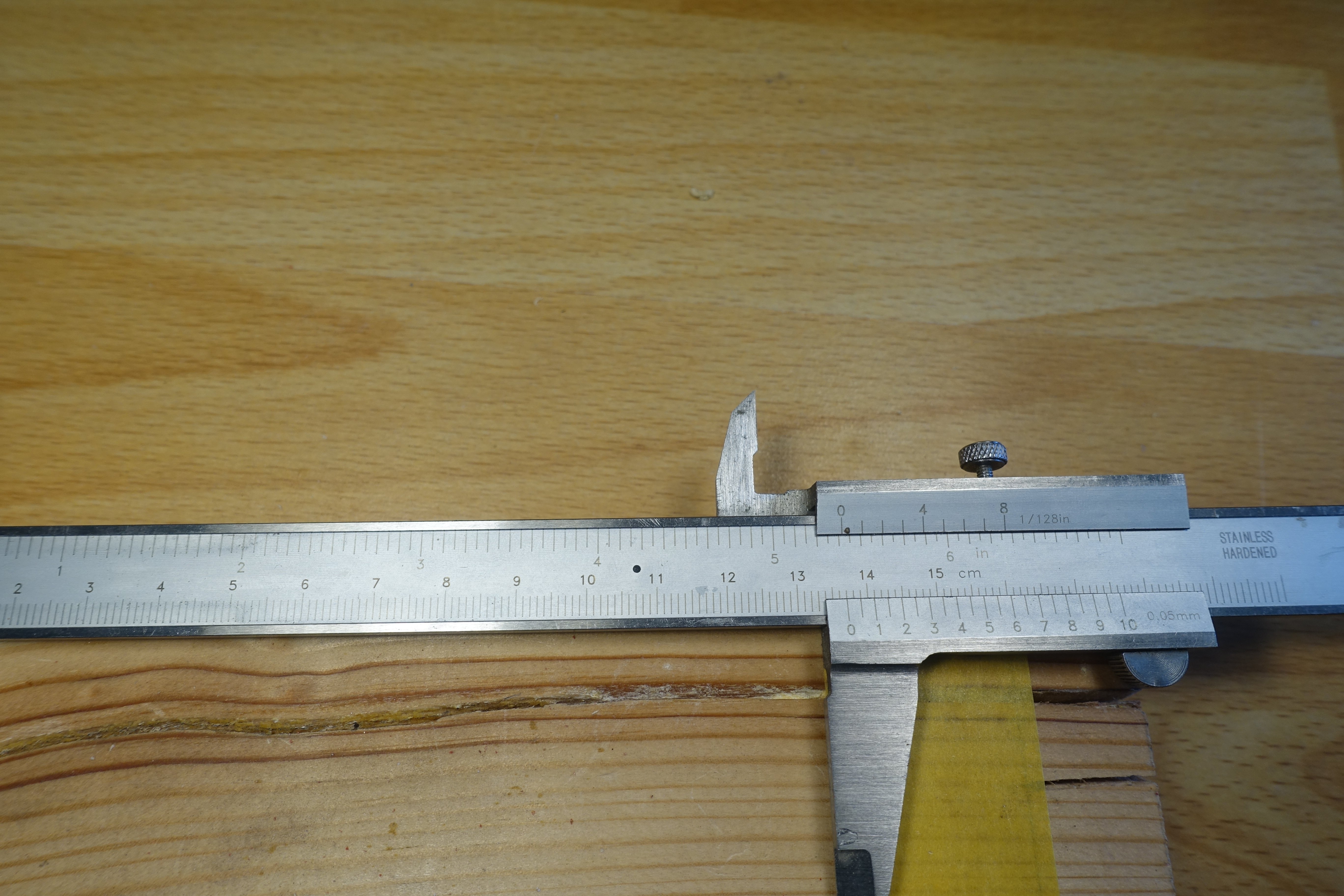
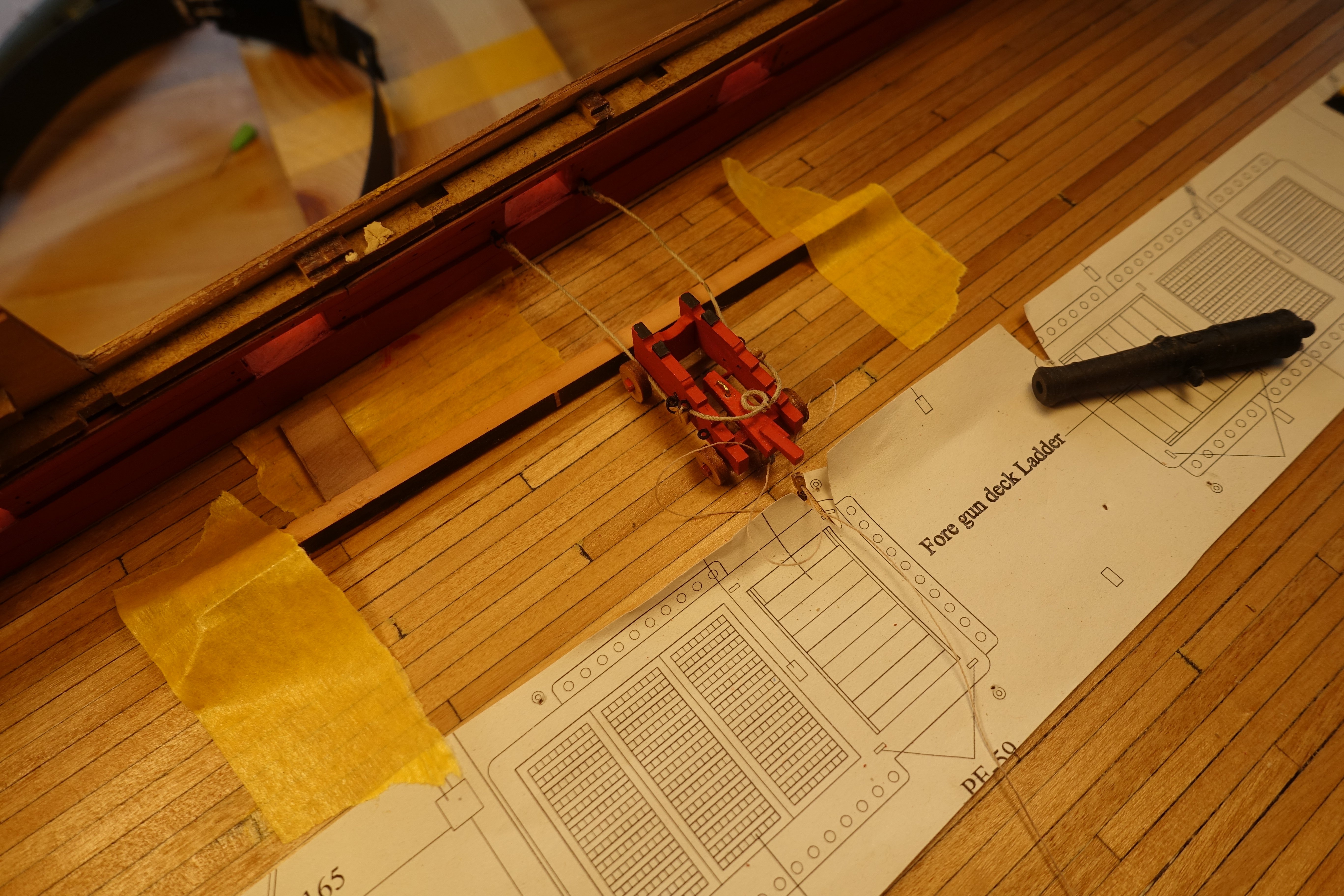
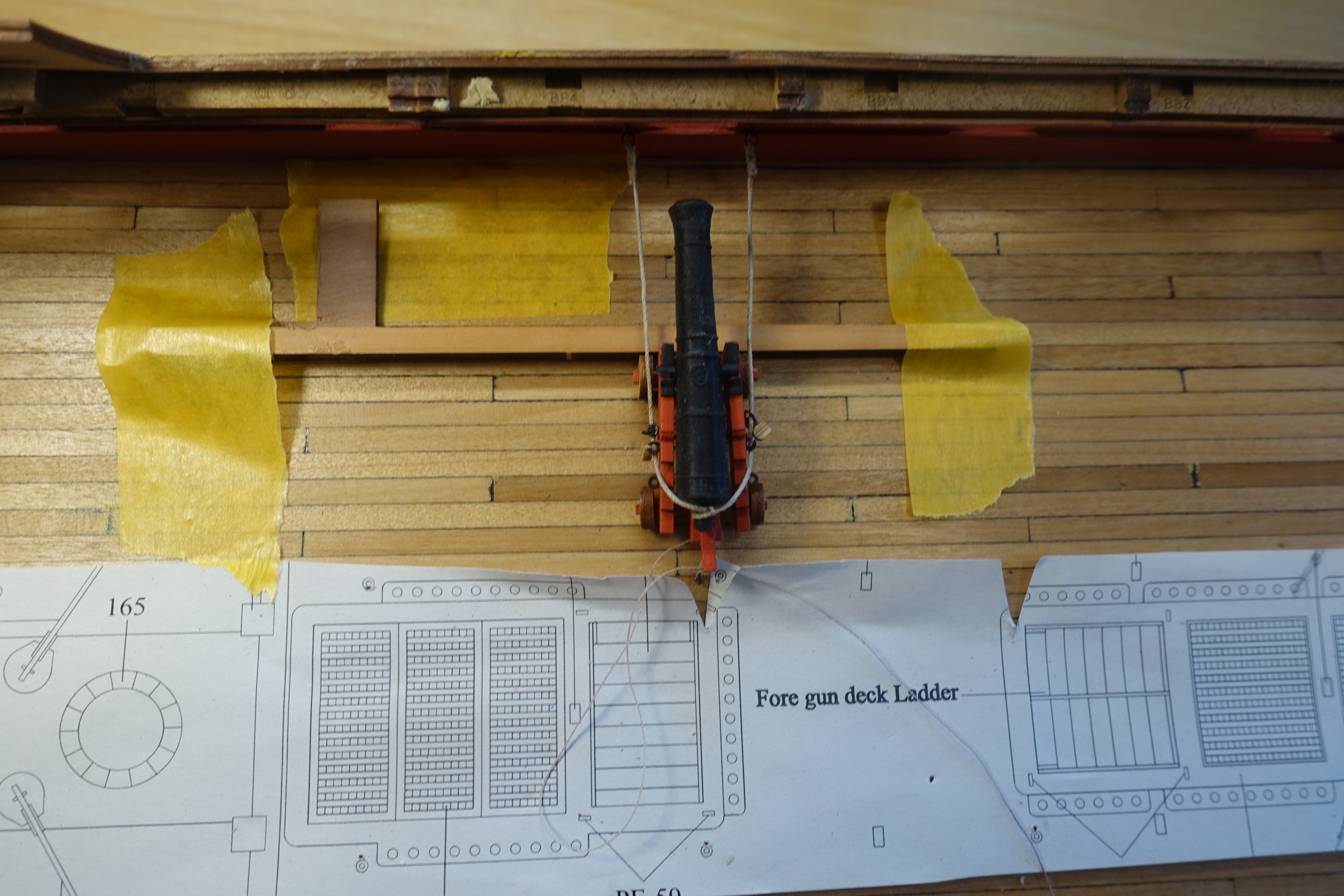
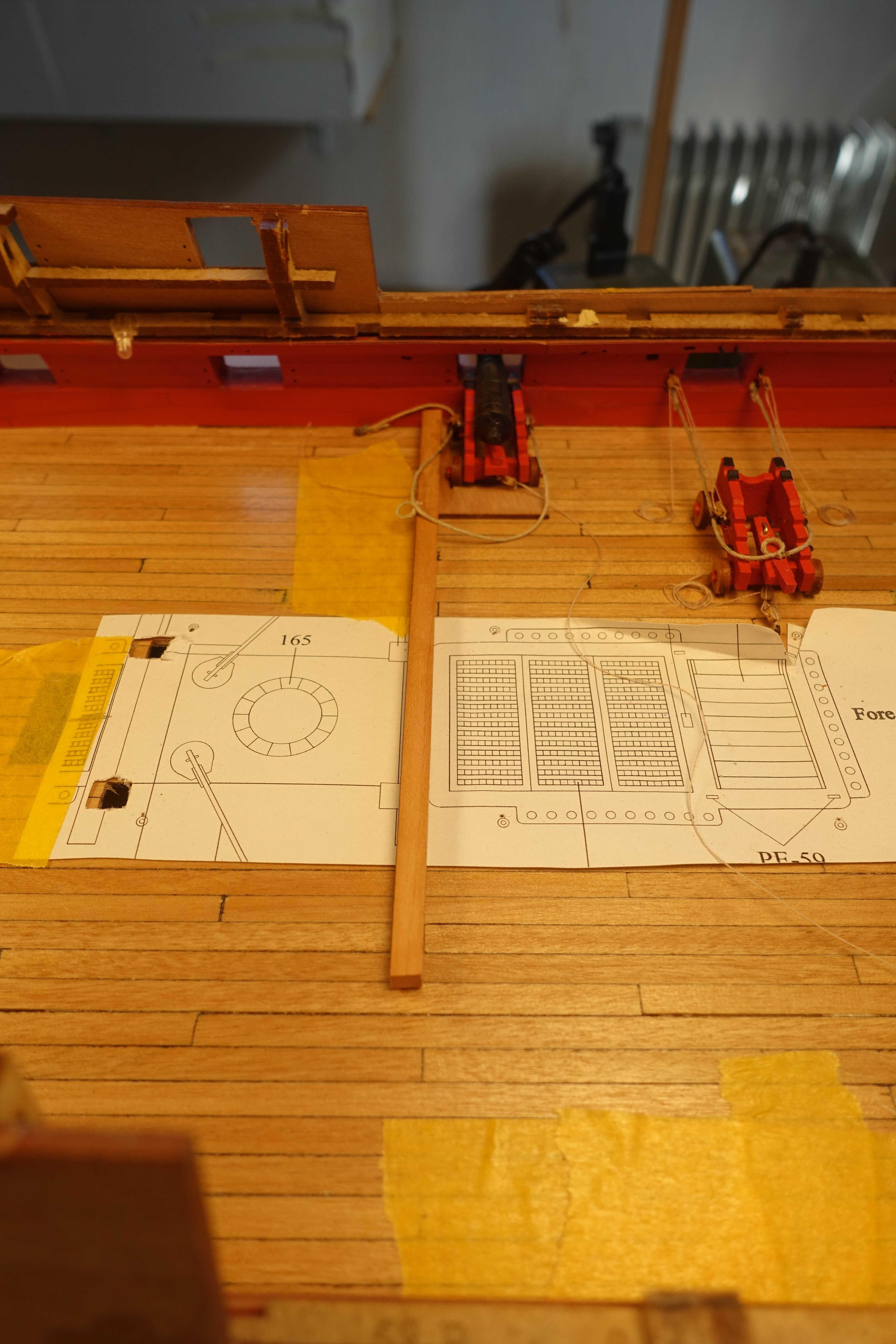
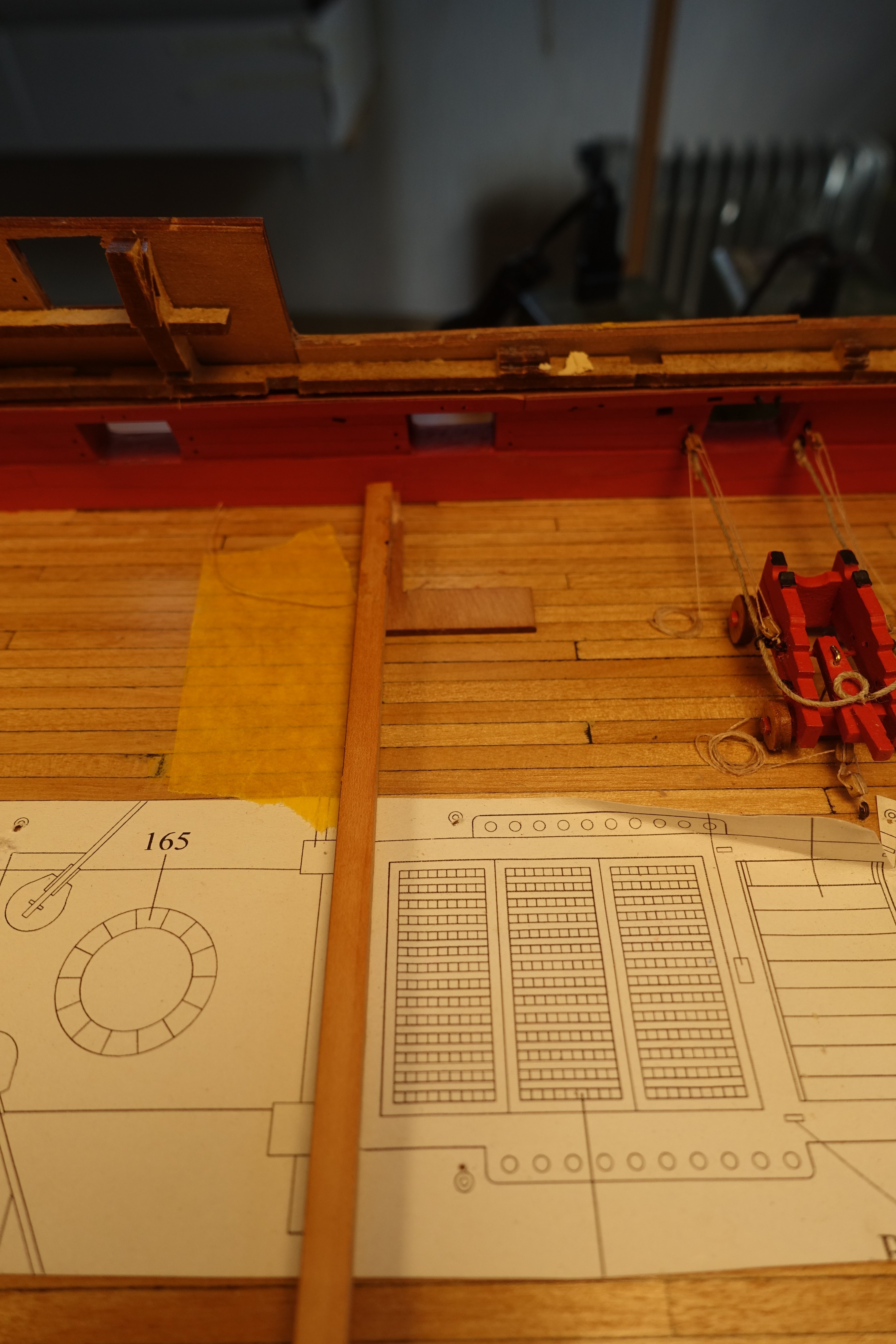
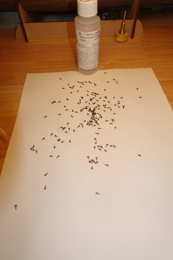
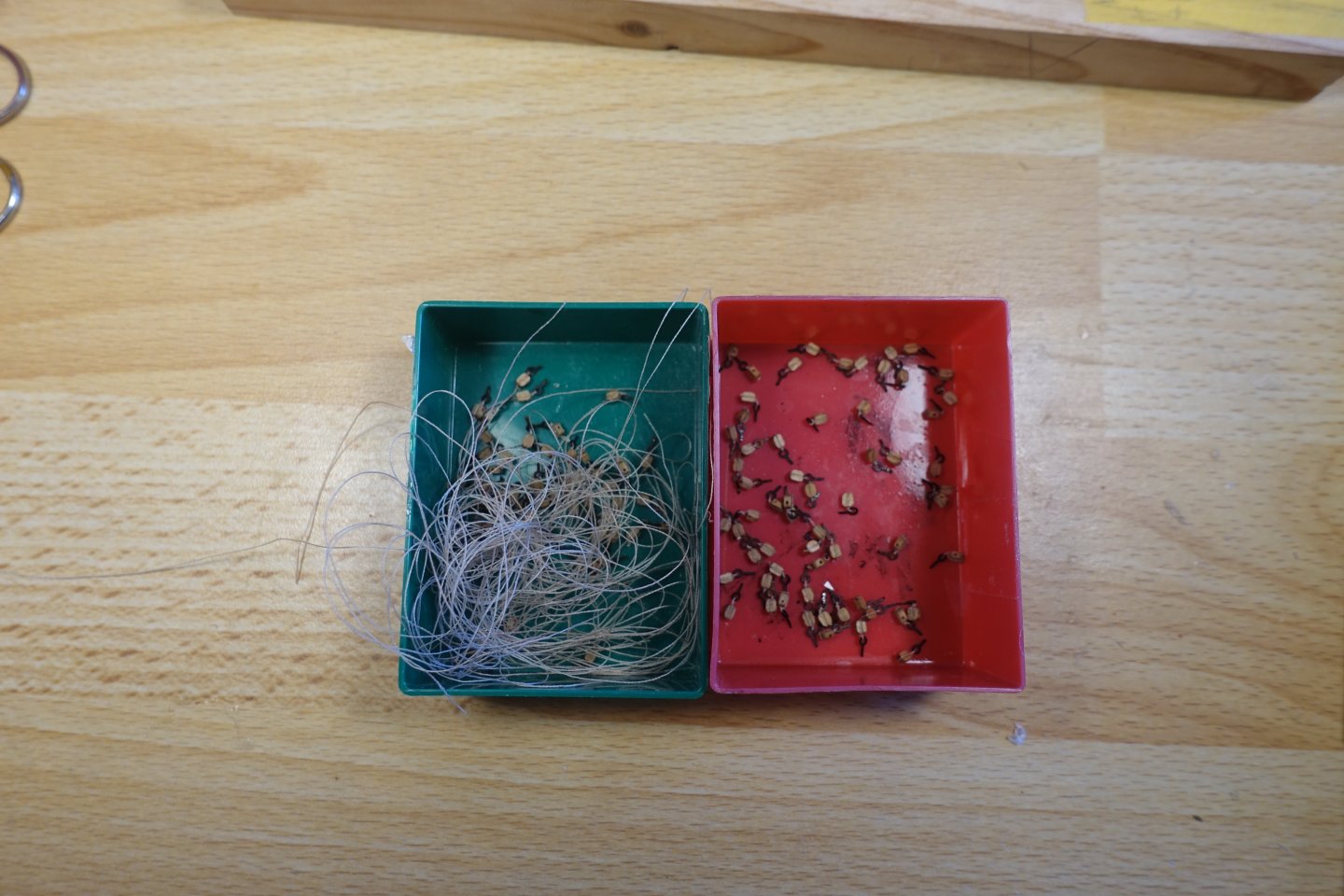
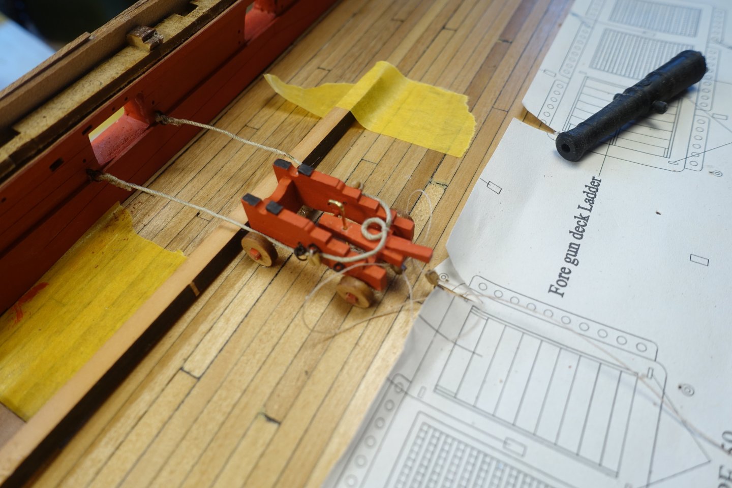
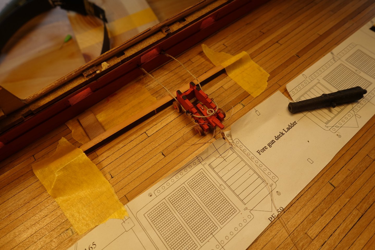
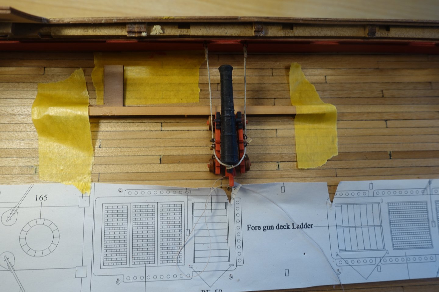
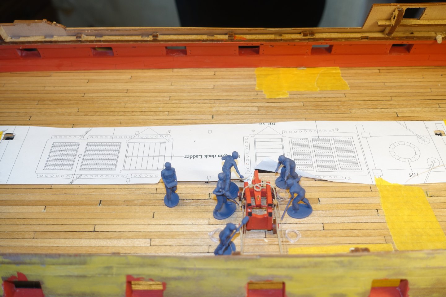
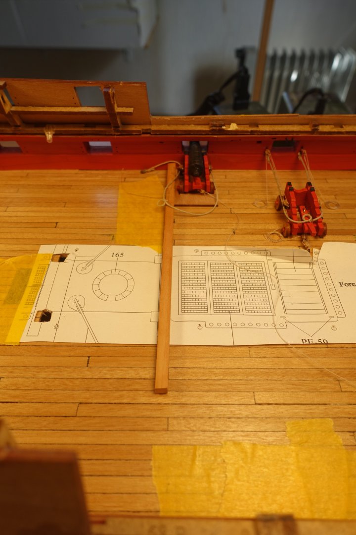
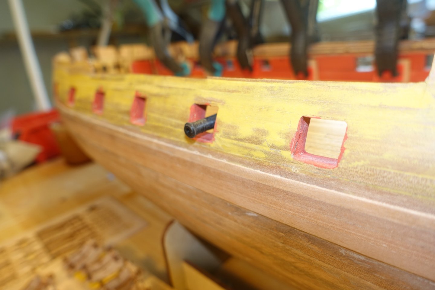
Cannons: Rigging and installation Since I want to open up the quarterdeck and the forecastle quite a bit, 10 of the 13 cannons on each side will be visible on deck. So I will rig 20 cannons including breech ropes. The eyebolts were degreased with isopropanol and then blackened. I then fitted 60 bolts/blocks (2mm) with rigging lines (0.1 mm) and attached 60 blocks to eyelets only. This is a task that allows a lot of time for contemplation. I want to display one of the cannons in a back position for loading with a gun crew in place. I used this cannon to determine the length of the breech ropes. There is always a risk of underestimating the length here. To make the breech ropes, including the ring bolts, I made a small auxiliary construction. The distance between the two ring bolts at the bulwark is 13.7 mm. I only made ring bolts for the breech ropes. As for the rigging, they would take up too much space and, in my opinion, thus make the model look unrealistic. The carriage in the back position was glued in place with cyanoacrylate. The carriage was then secured to the deck with 0.7mm brass wire. I have also tried out the positioning of the gun crew (also from Chris/Vanguard). I built a small aid to help positioning the other cannons. The remaining cannons will be completed and installed in the near future.


-
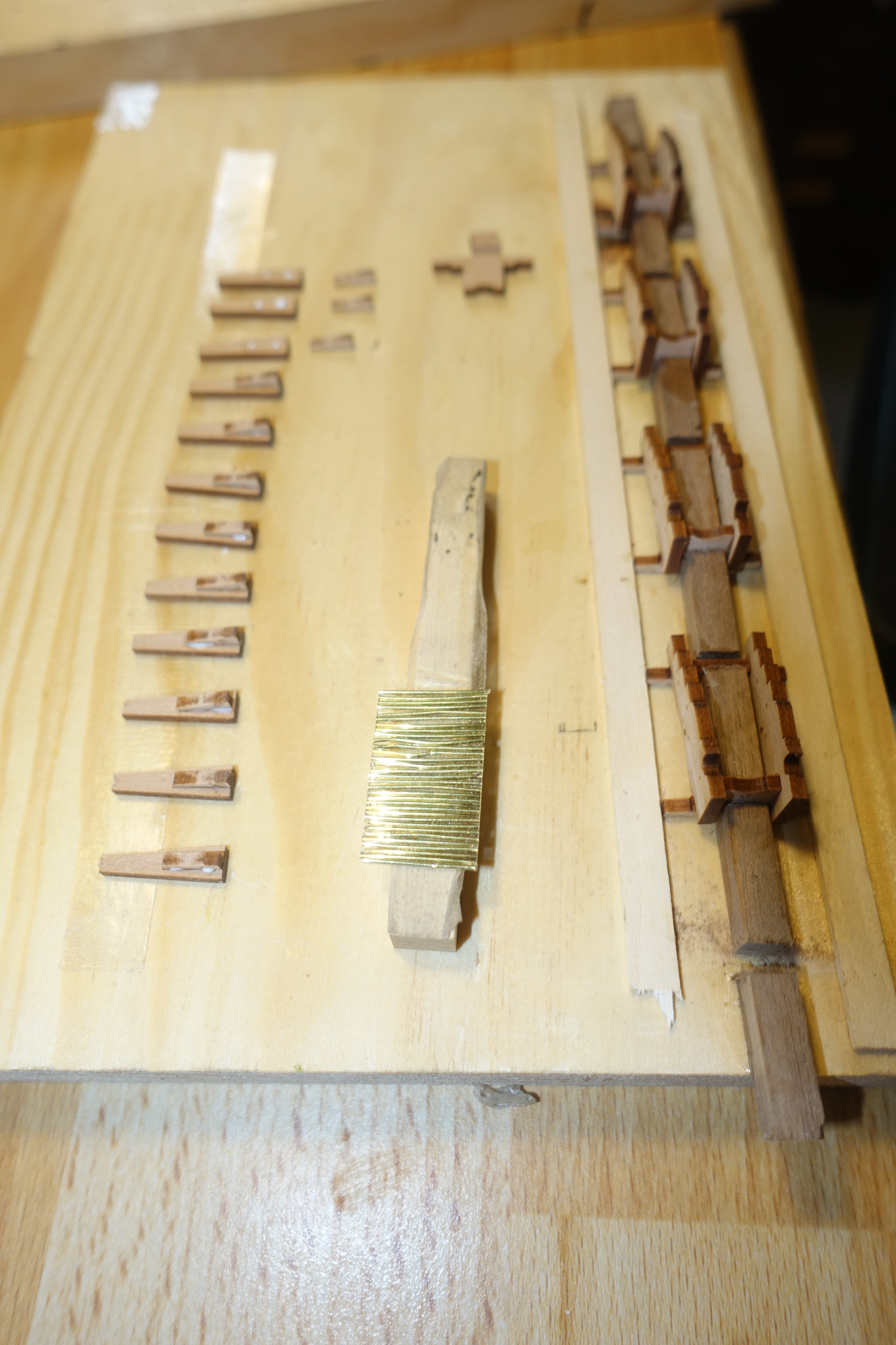
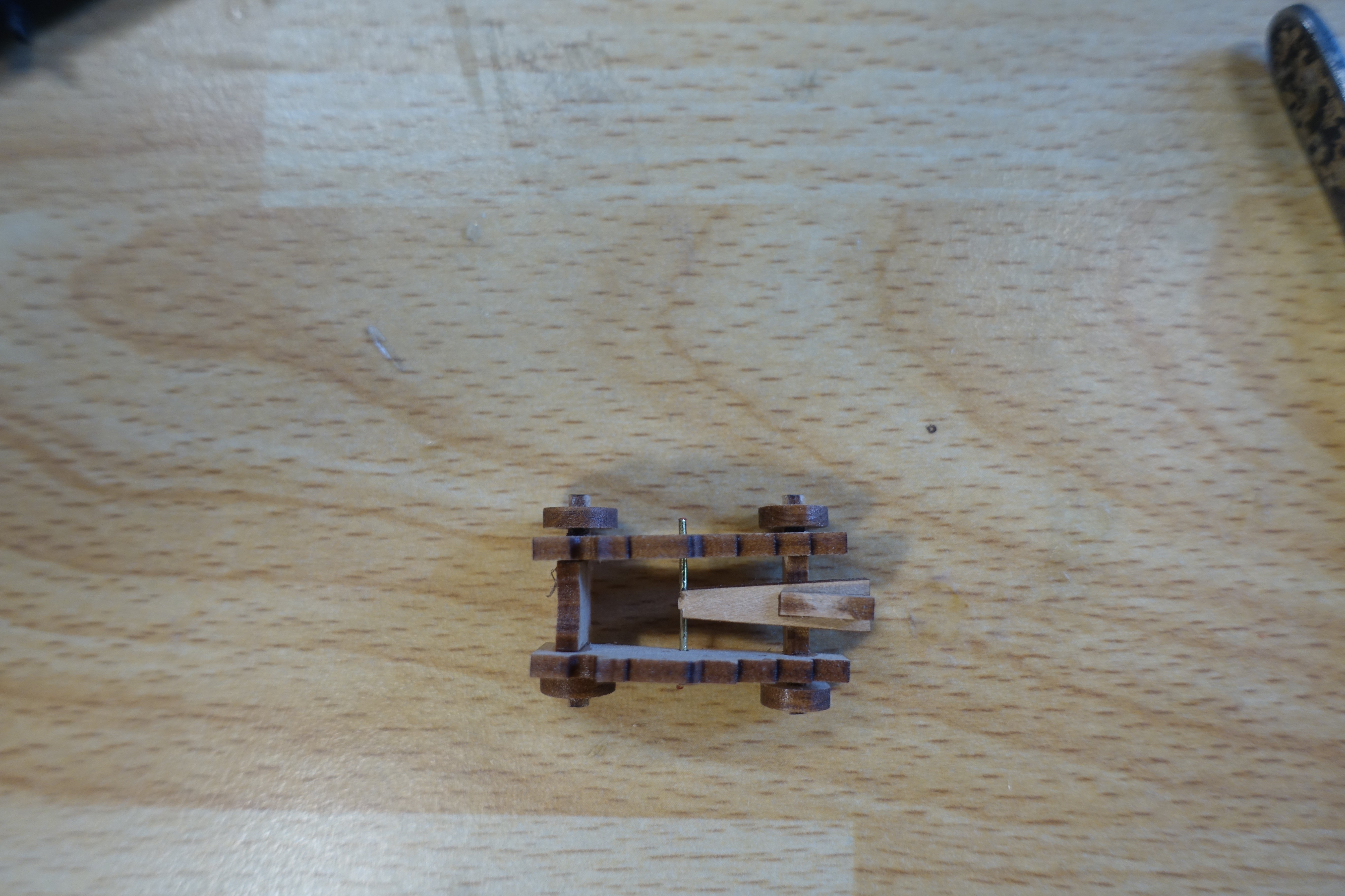
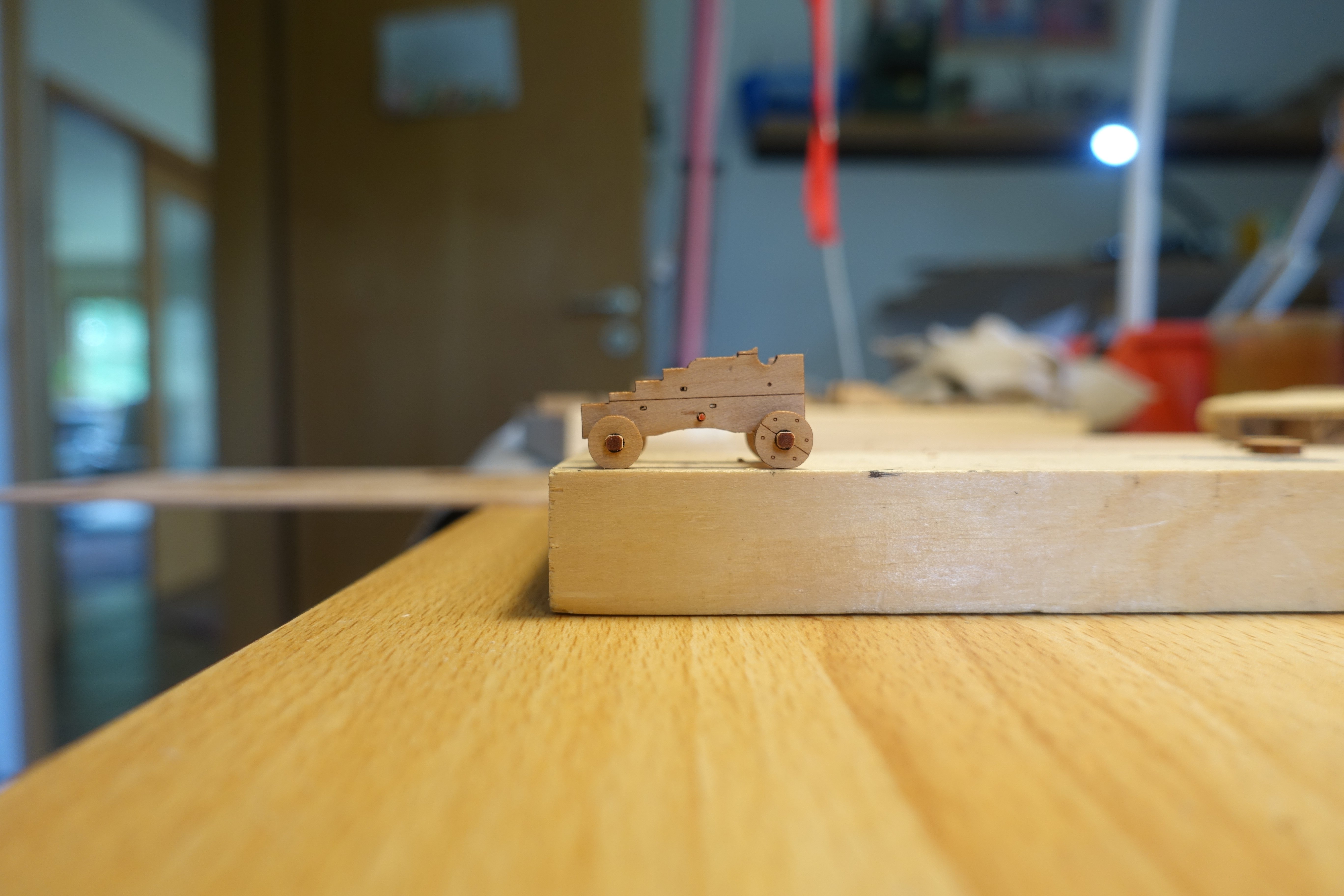
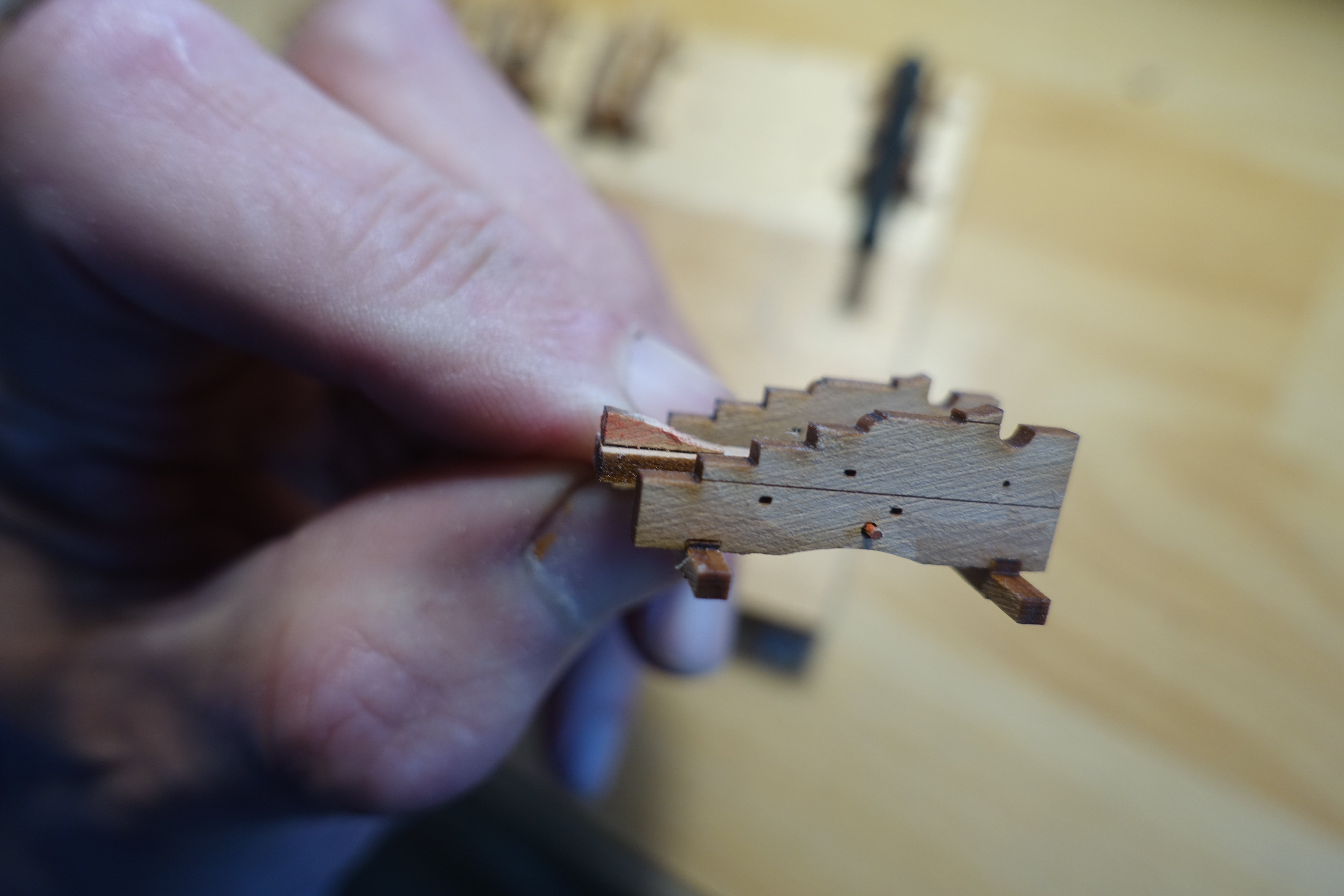
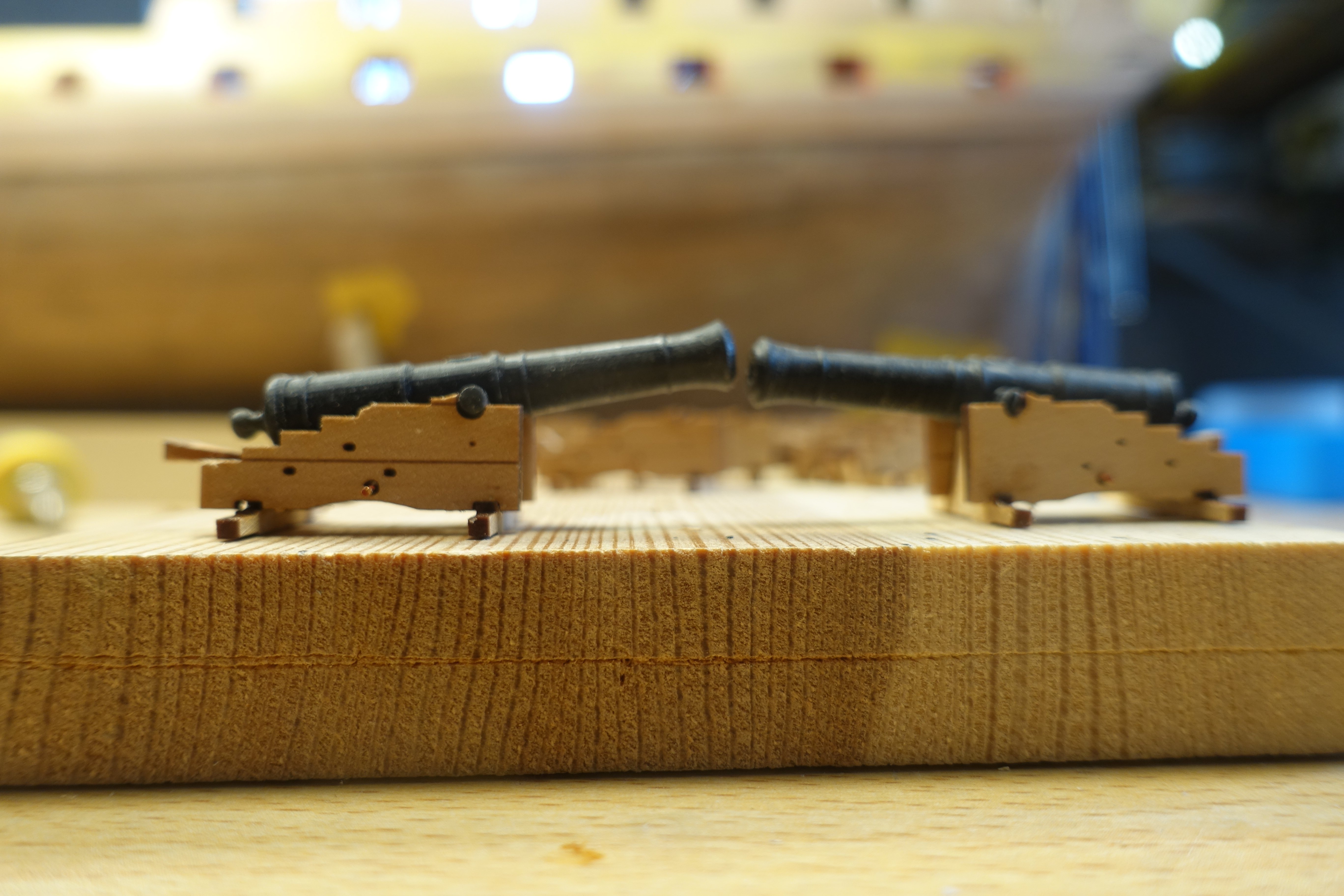
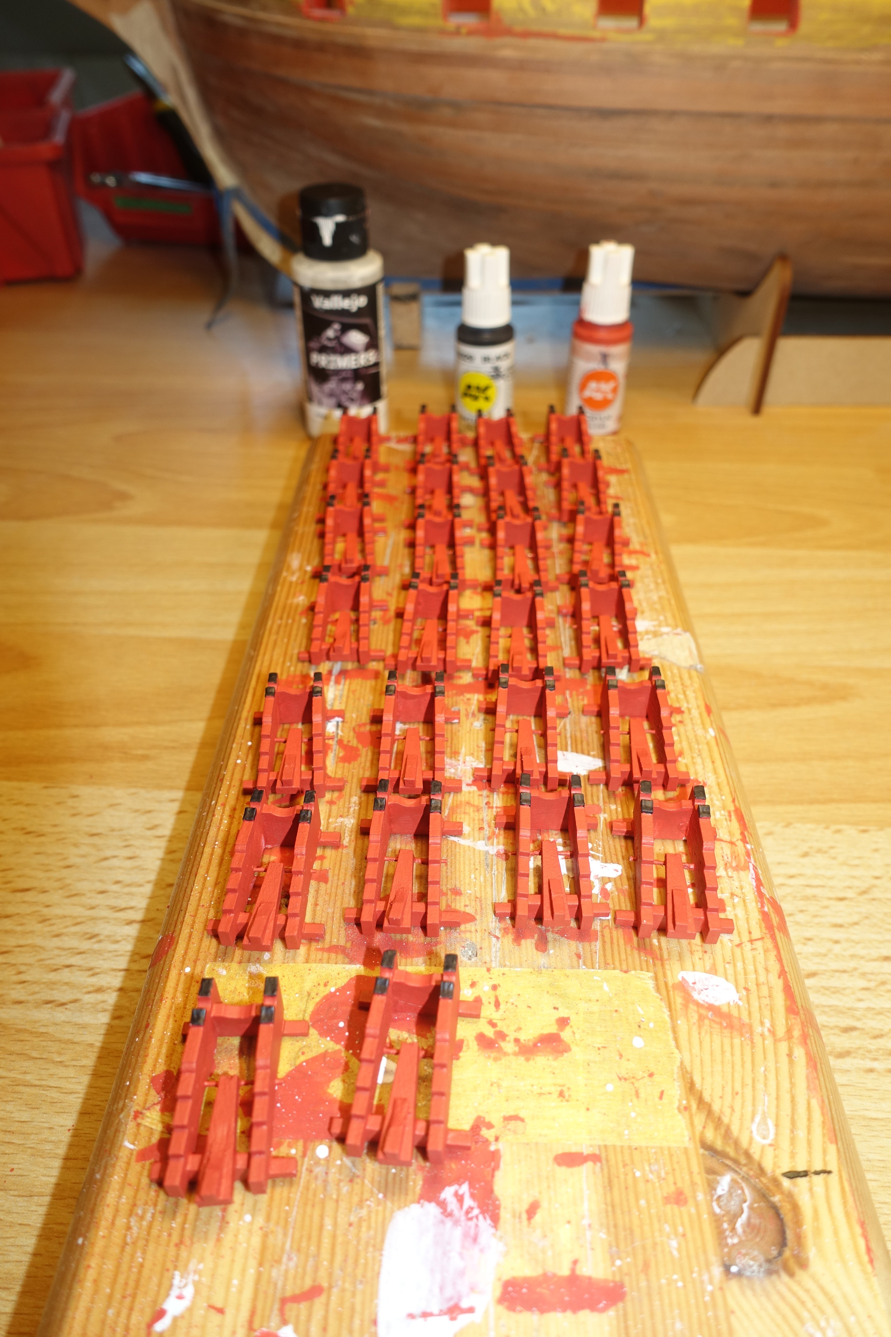
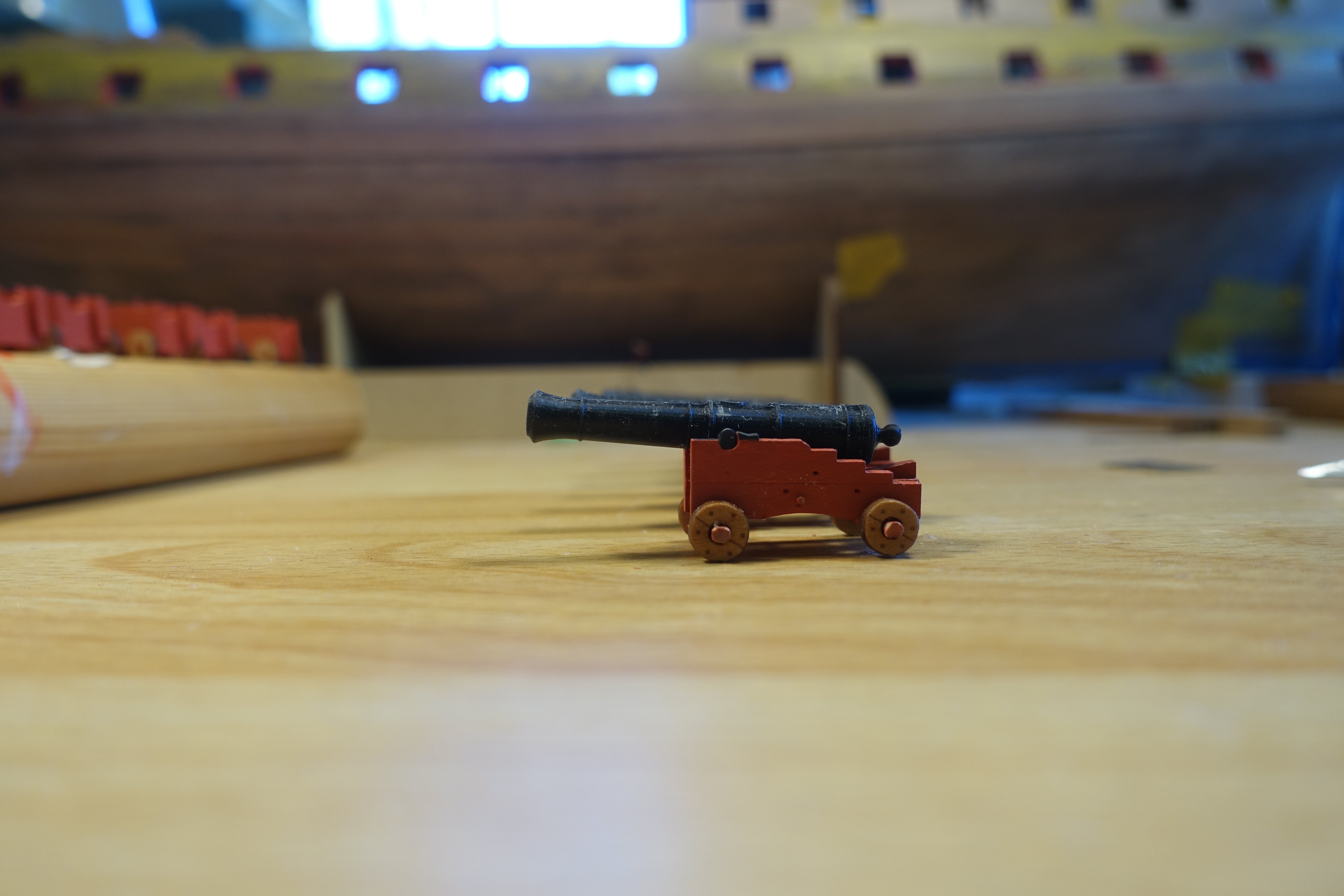
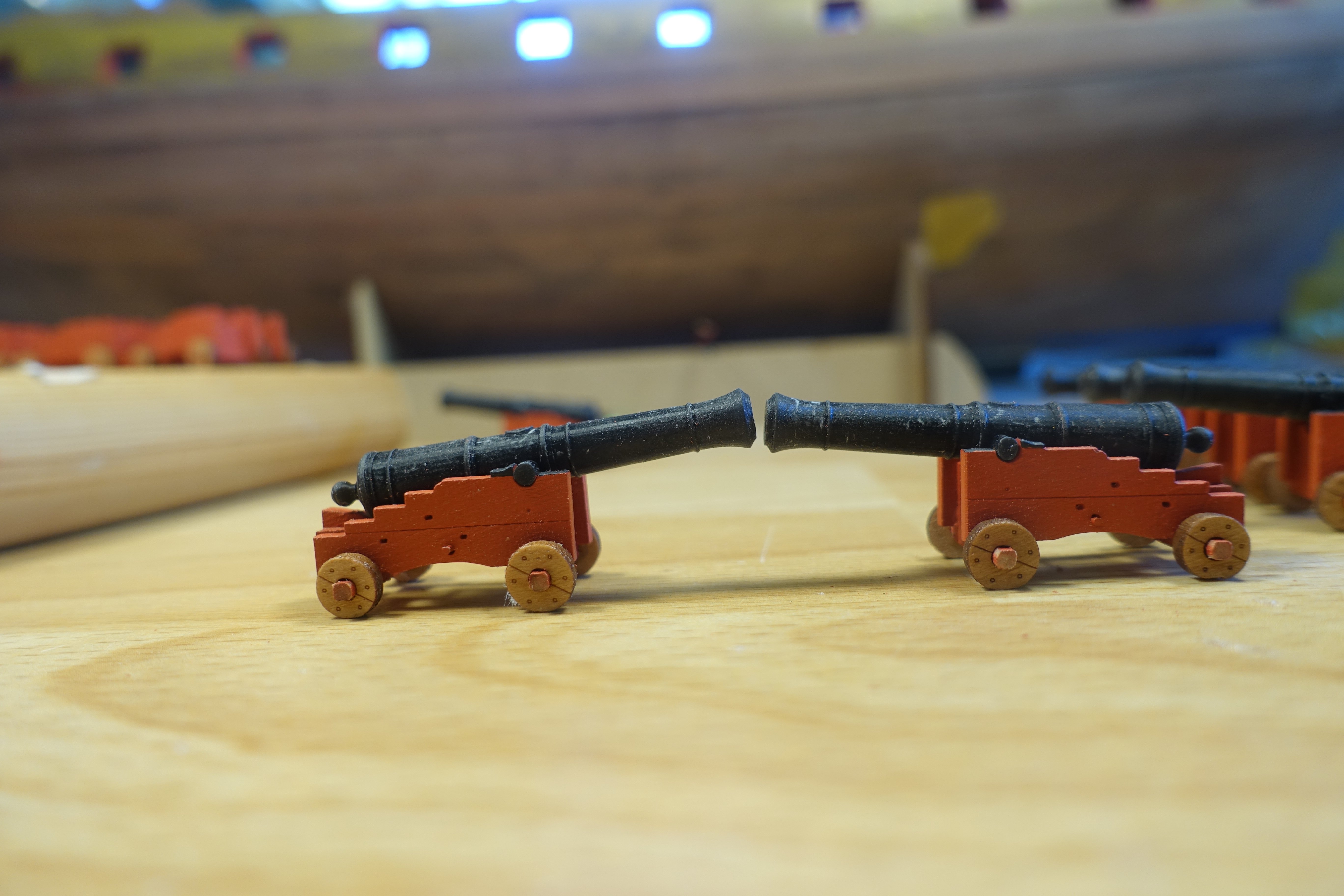
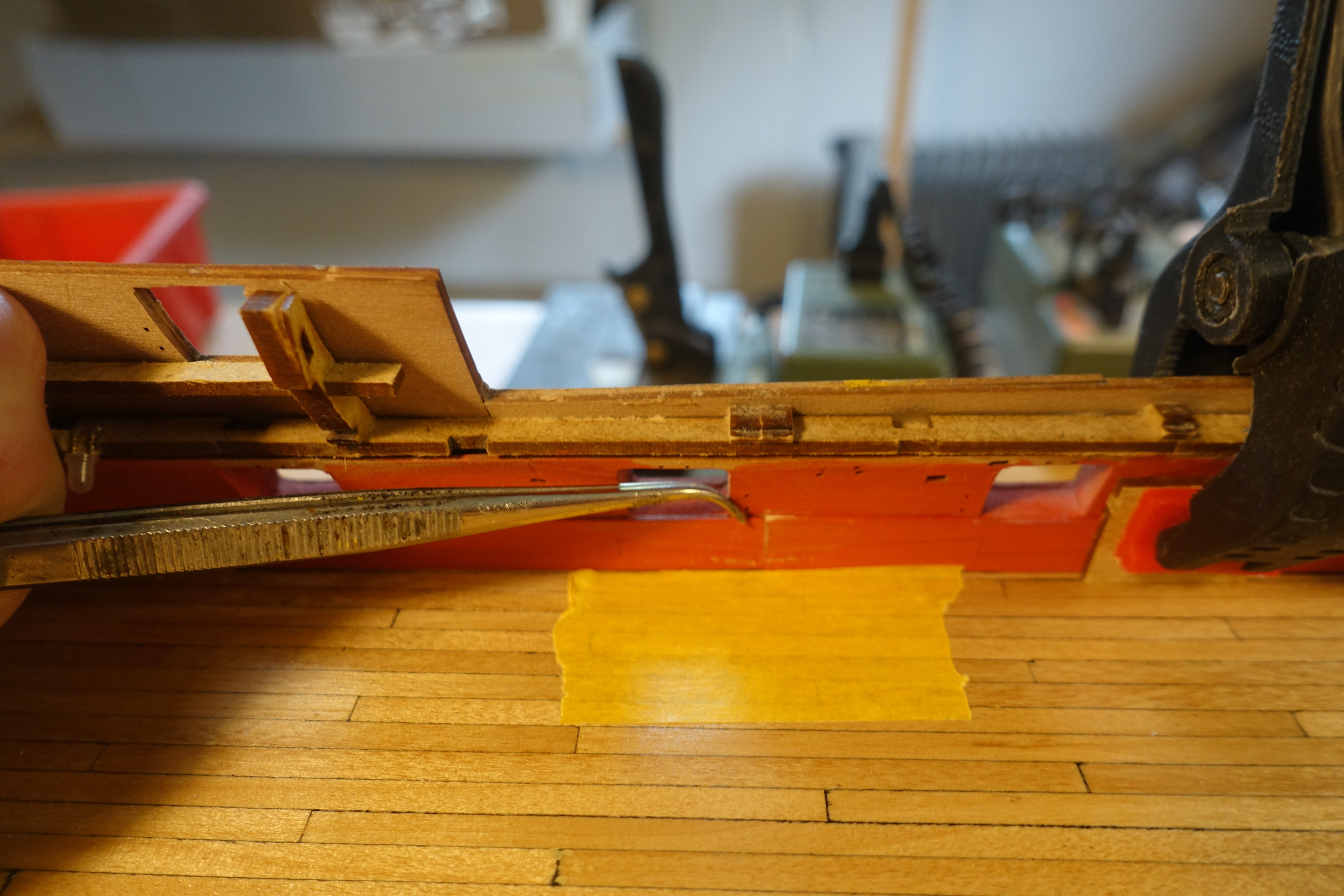
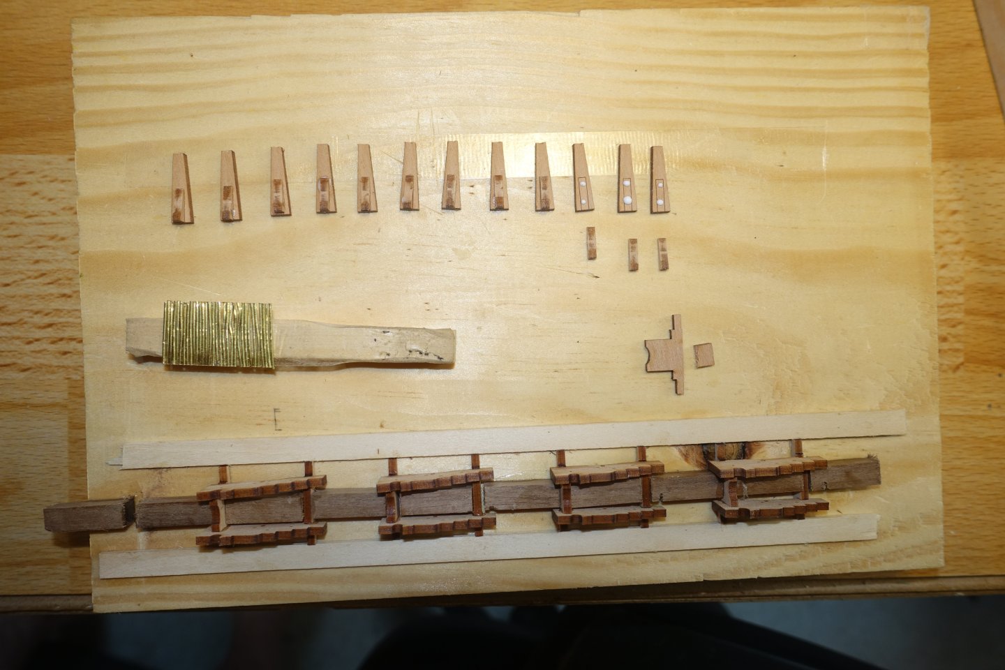
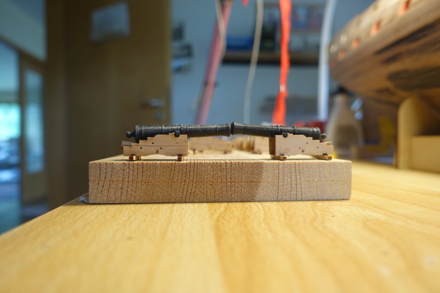
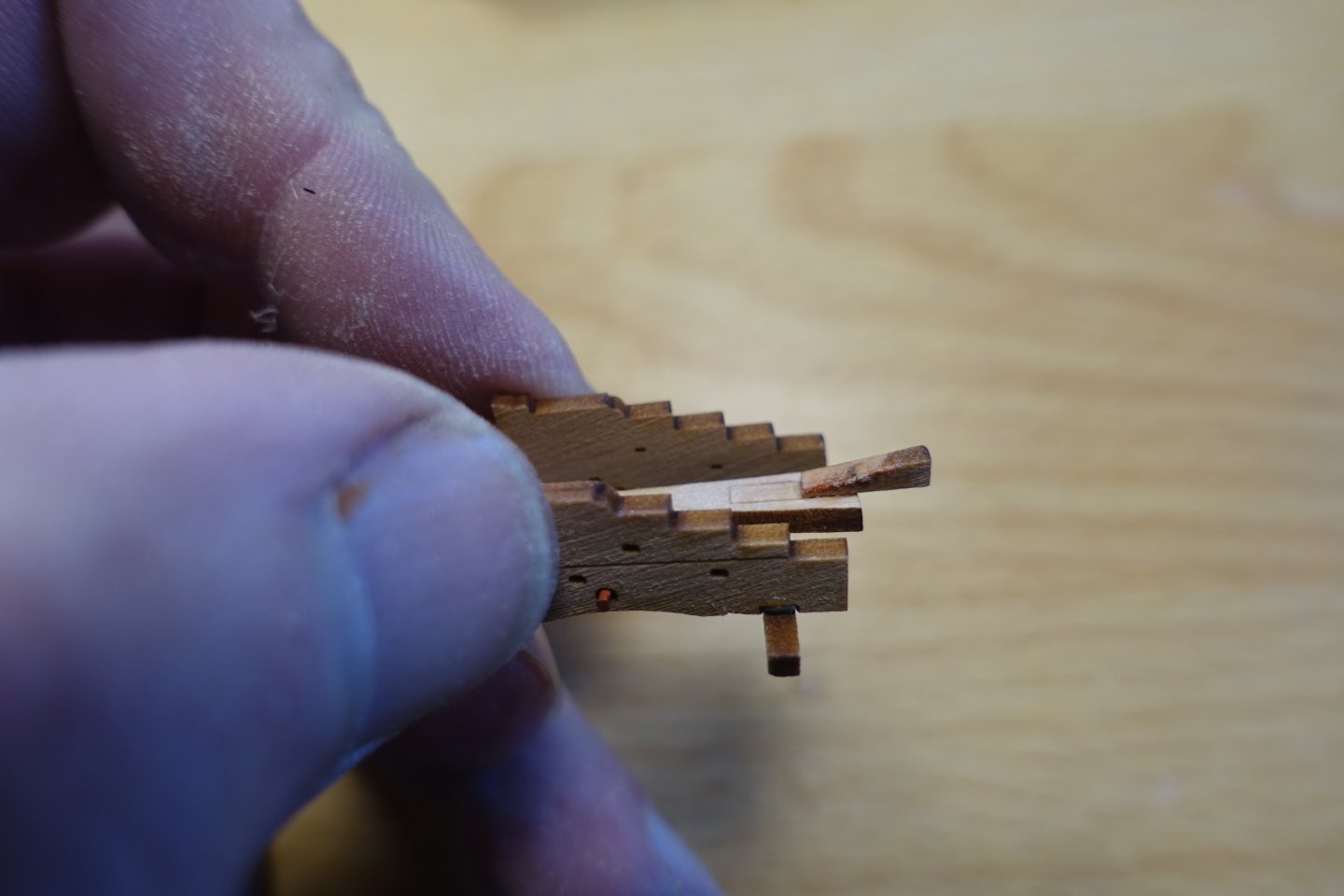
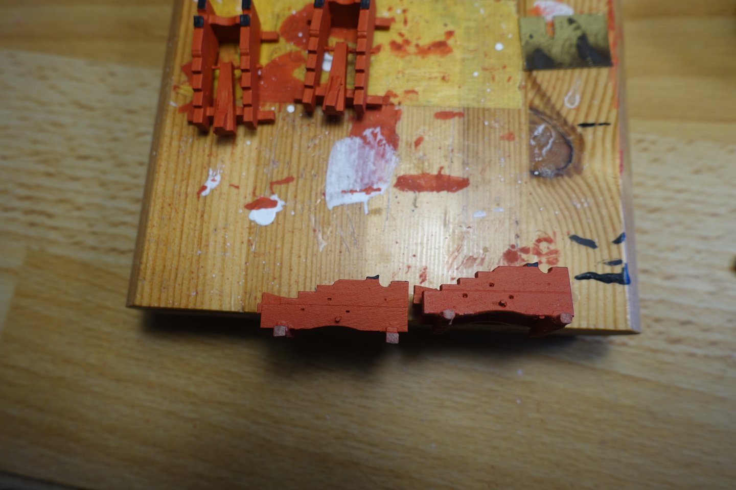
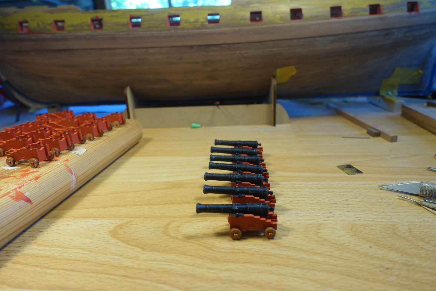
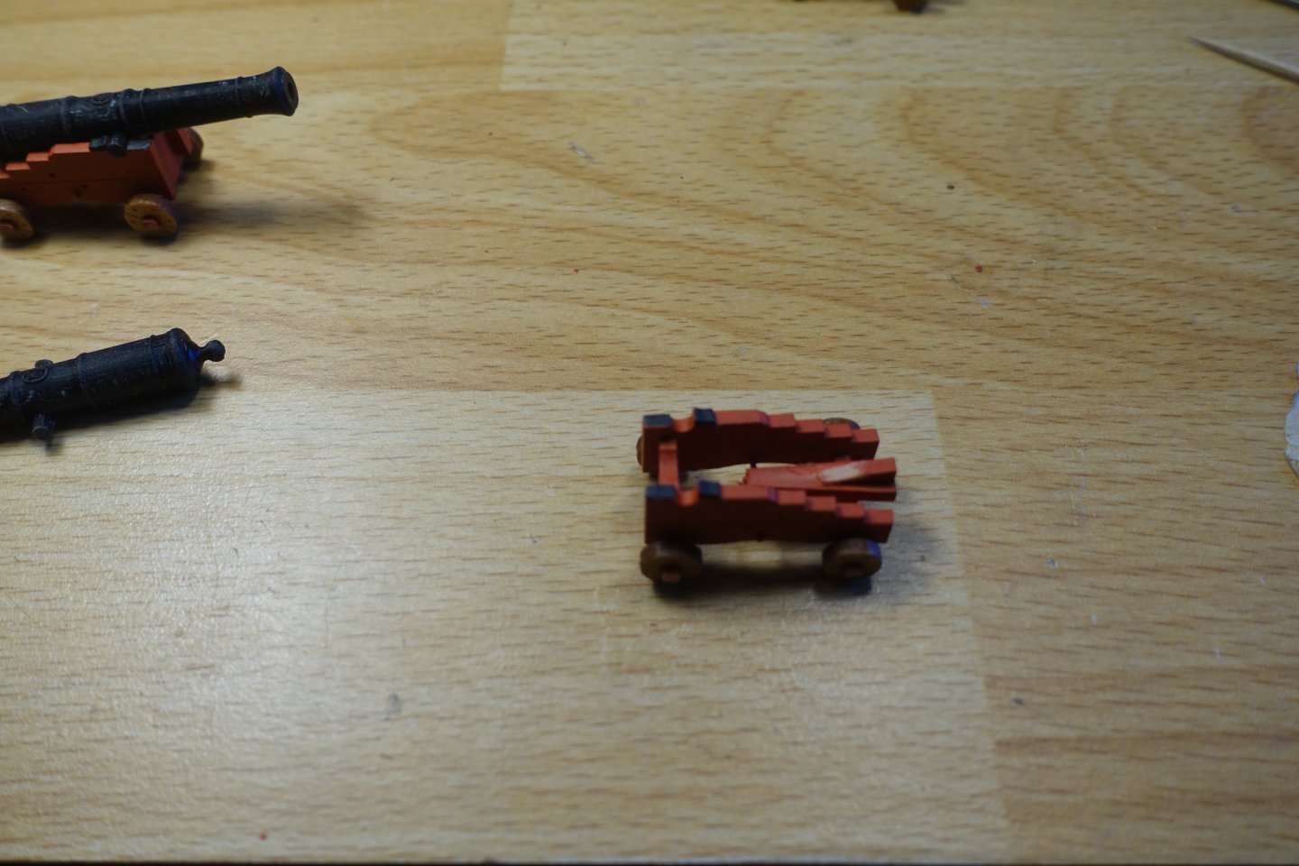
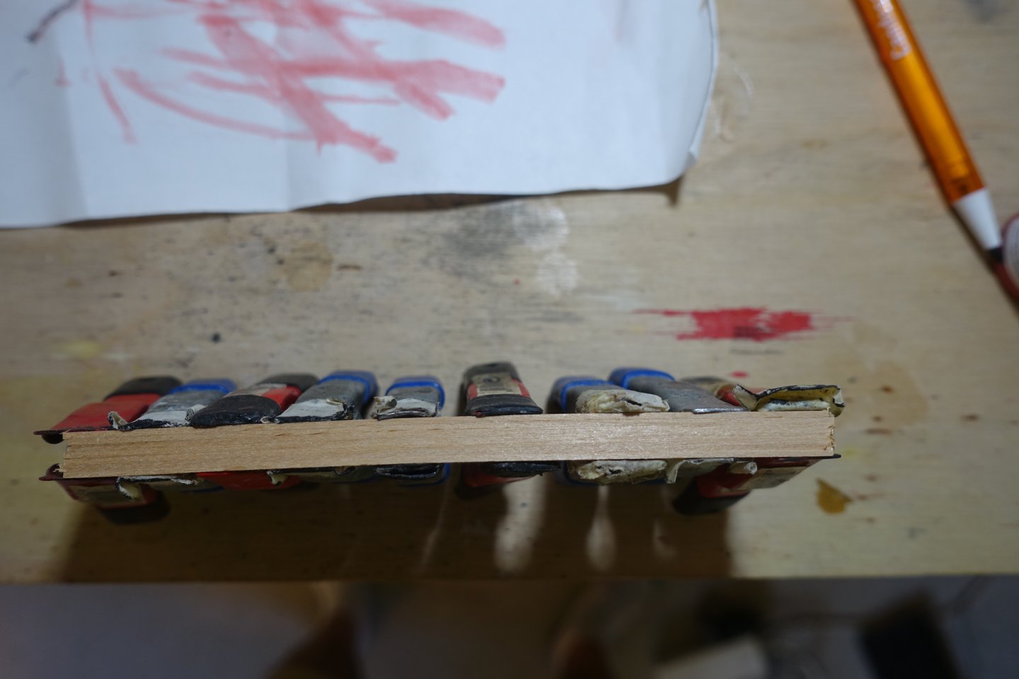
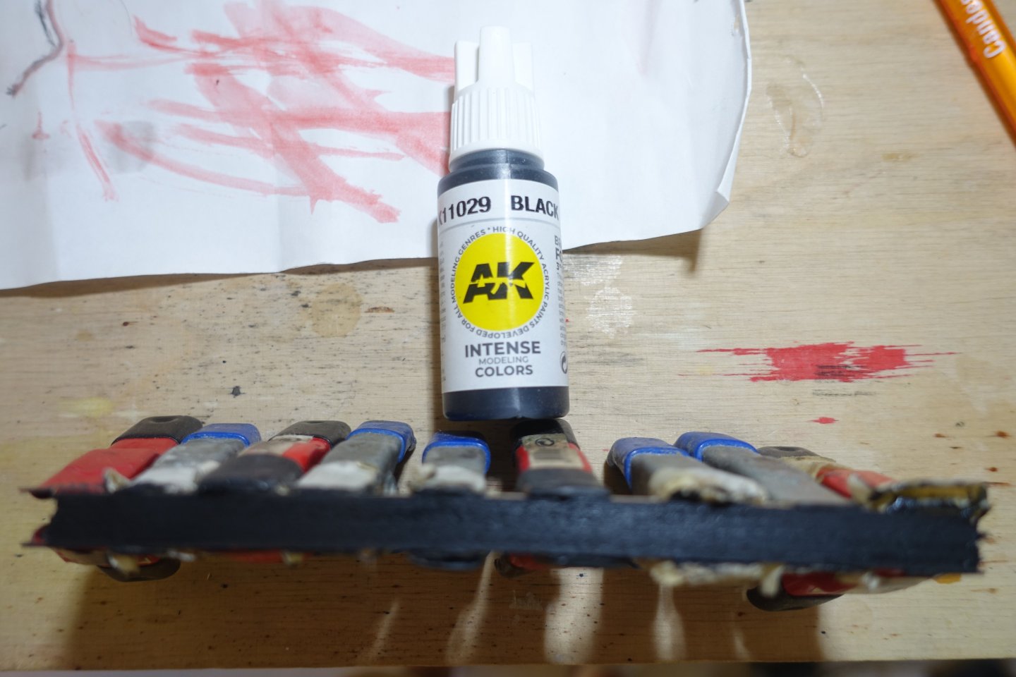
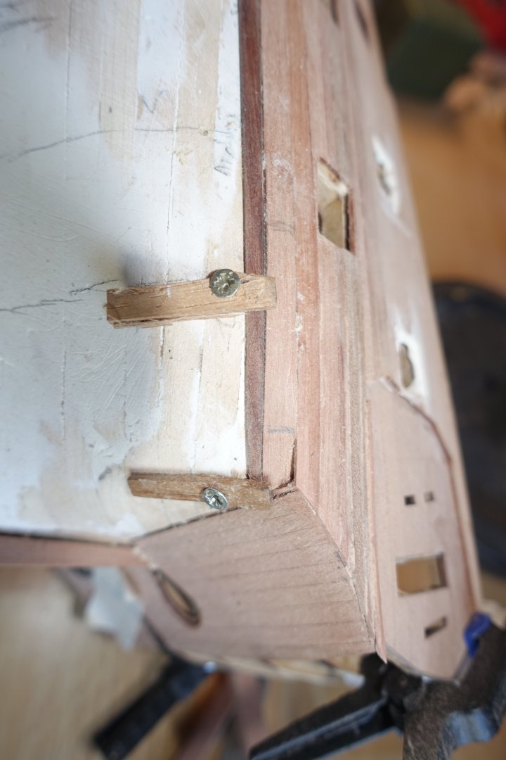
Cannons: Assembly I have now started on the cannons (before attaching the various deck structures), as there is still space on the deck and I want to rig the cannons and also show one cannon in a loading state, with a gun crew. Once the other structures are in place, it will be more difficult to handle the cannons. Several building reports describe a holding device for the carriage parts. I built something similar and used it to glue the carriages together. Chris has provided a tab on the front of the carriages that fits into recesses in the deck. Since I planked over the recesses, I cut off the tab. I have never found the alignment of the guns to be a problem in my previous builds. I will secure the carriages with a brass pin. The support rods for the quion are glued on with double-sided adhesive tape and cut/sanded to the same length. The support boards for the quions are also fixed with double-sided adhesive tape. This makes it easier (at least for me) to glue the quions in place. The support boards were glued so that the barrels only marginally rest on the quions. To check the levelling of the carriages with the gun barrel, I equipped one with wheels. To do this, the axles had to be sanded down slightly. Complete round grinding would cause the wheels to wobble. The mounting of the barrels on the quions was tested and the alignment in the ship was checked and adjusted. The adjusted carriage was used to align the other carriages by comparing the height of the gun barrels. The picture shows that the left barrel is slightly lower. To adjust this, the quion was slightly sanded down. And so the gun barrels were brought to (almost) the same height. This was done for all carriages. I want to show the loading process for one cannon. To do this, the cannons were usually raised slightly so that the powder bag and projectile did not fall out again. For this one cannon, the quion was then moved backwards so that the barrel of this cannon was slightly higher than the others. The carriages were coated with diluted primer before painting. Otherwise, the paint would not adhere well, especially to the areas charred by the laser (which were difficult to sand down). As I do not have an airbrush, the paint was applied with a brush. As with the test carriage, the axles were slightly bevelled for attaching the wheels so that the wheels could be easily attached but still sat firmly. Left carriage without bevelling. Right carriage with bevelling. After attaching the wheels, the heights of the gun barrels were compared again. No differences were noticeable on most of them. A row of 7 guns. On two carriages, the barrel was too deep. Here, the quion was resanded. Next, I will prepare everything for rigging and securing the guns on deck.


-
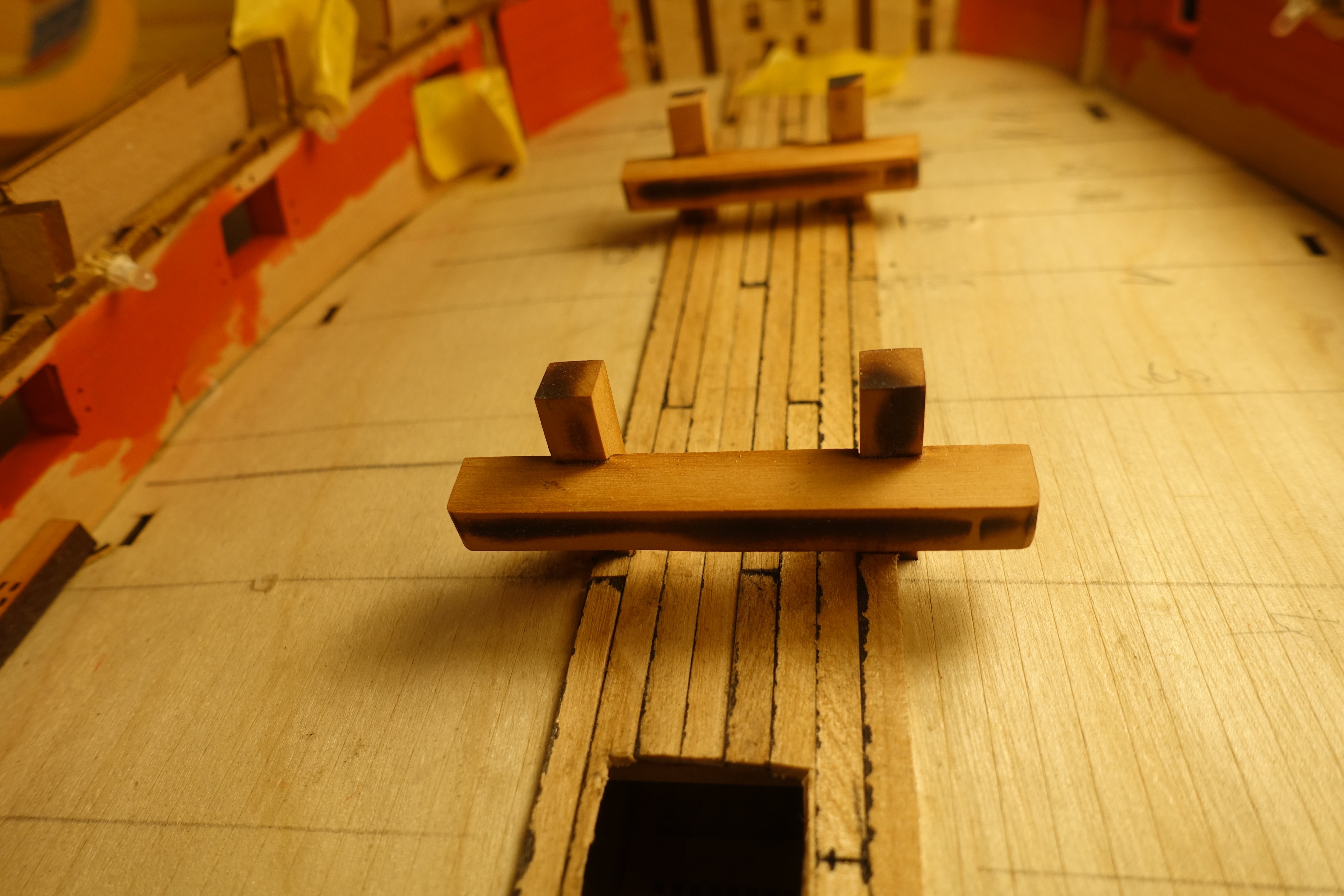
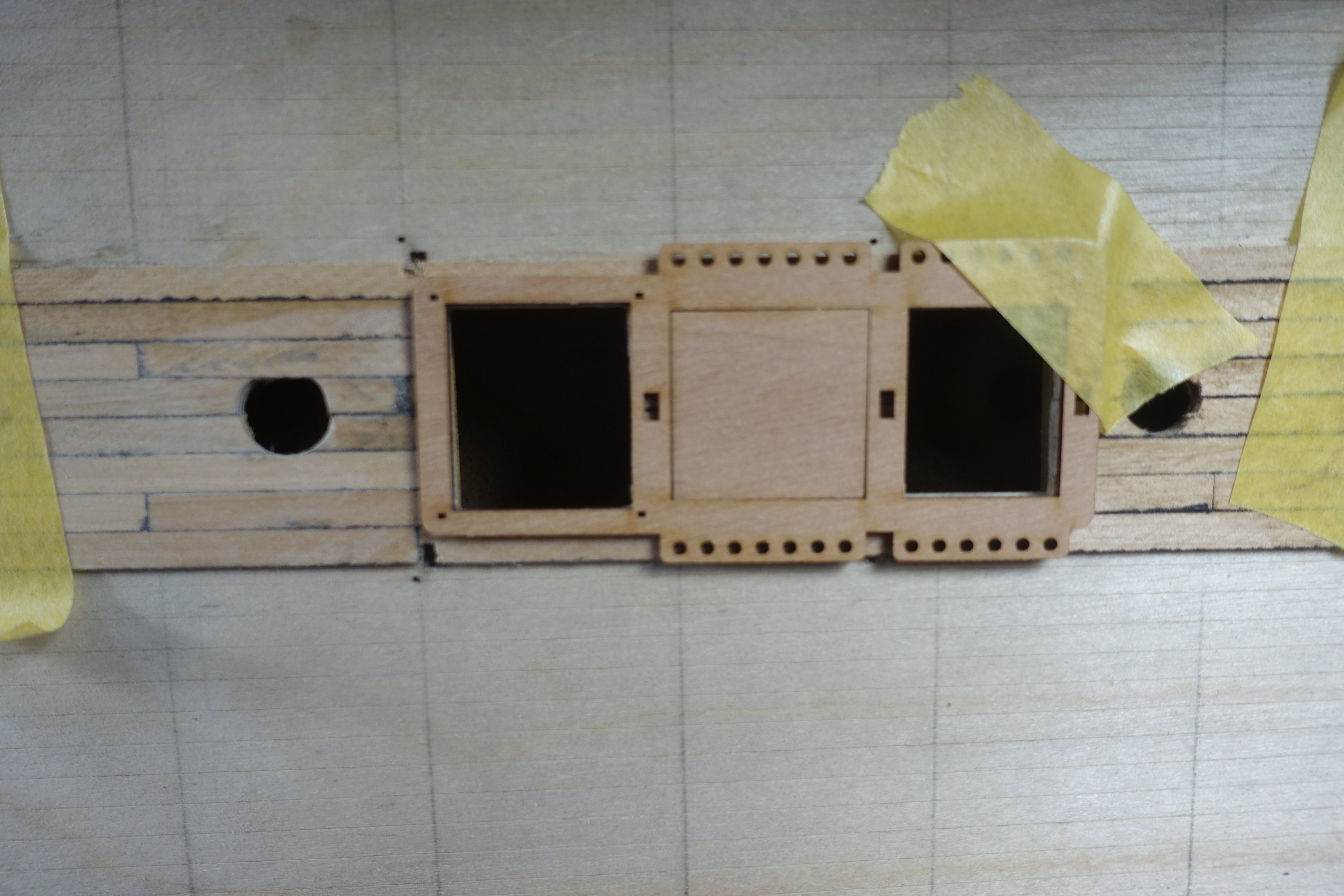
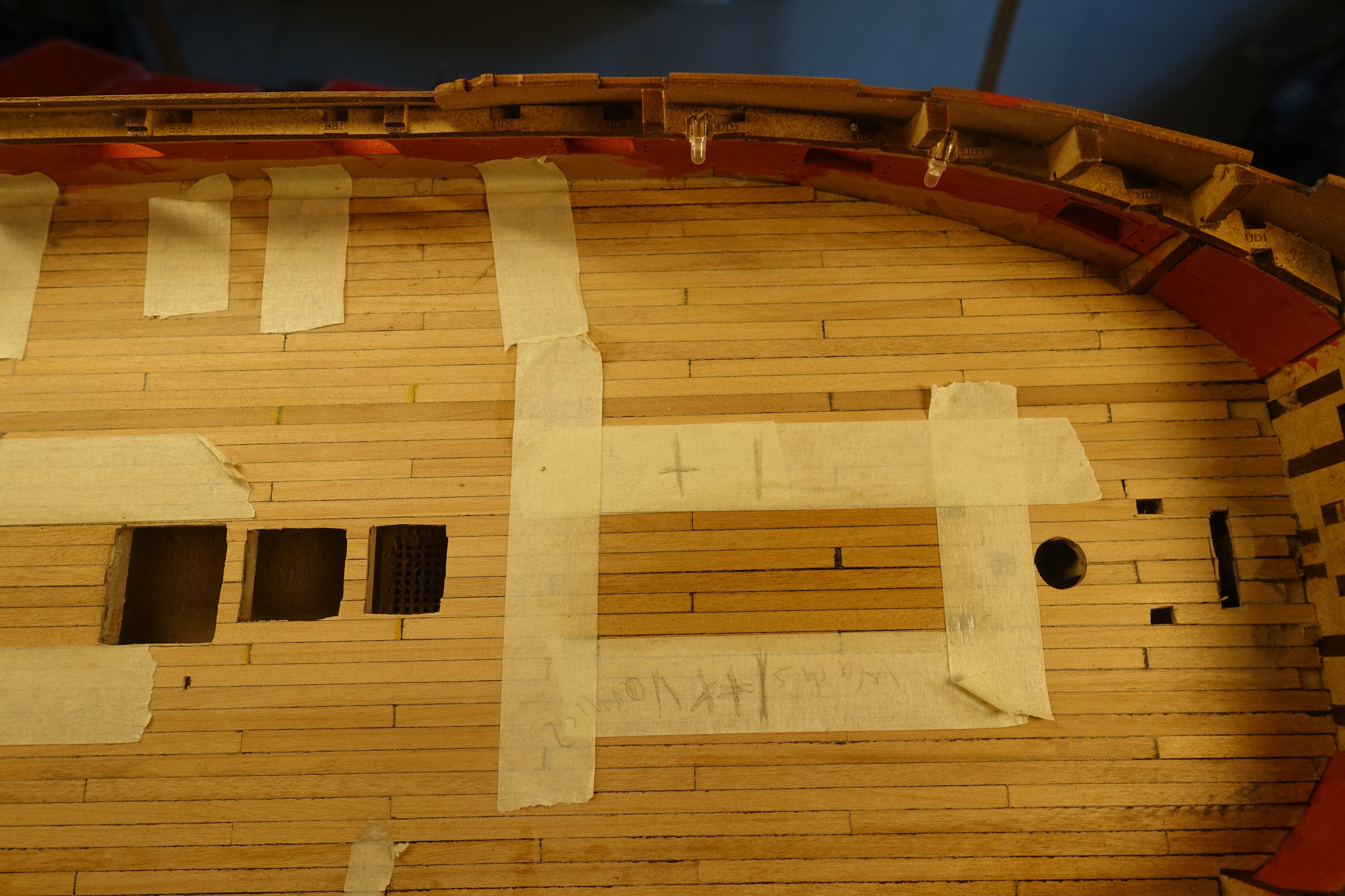
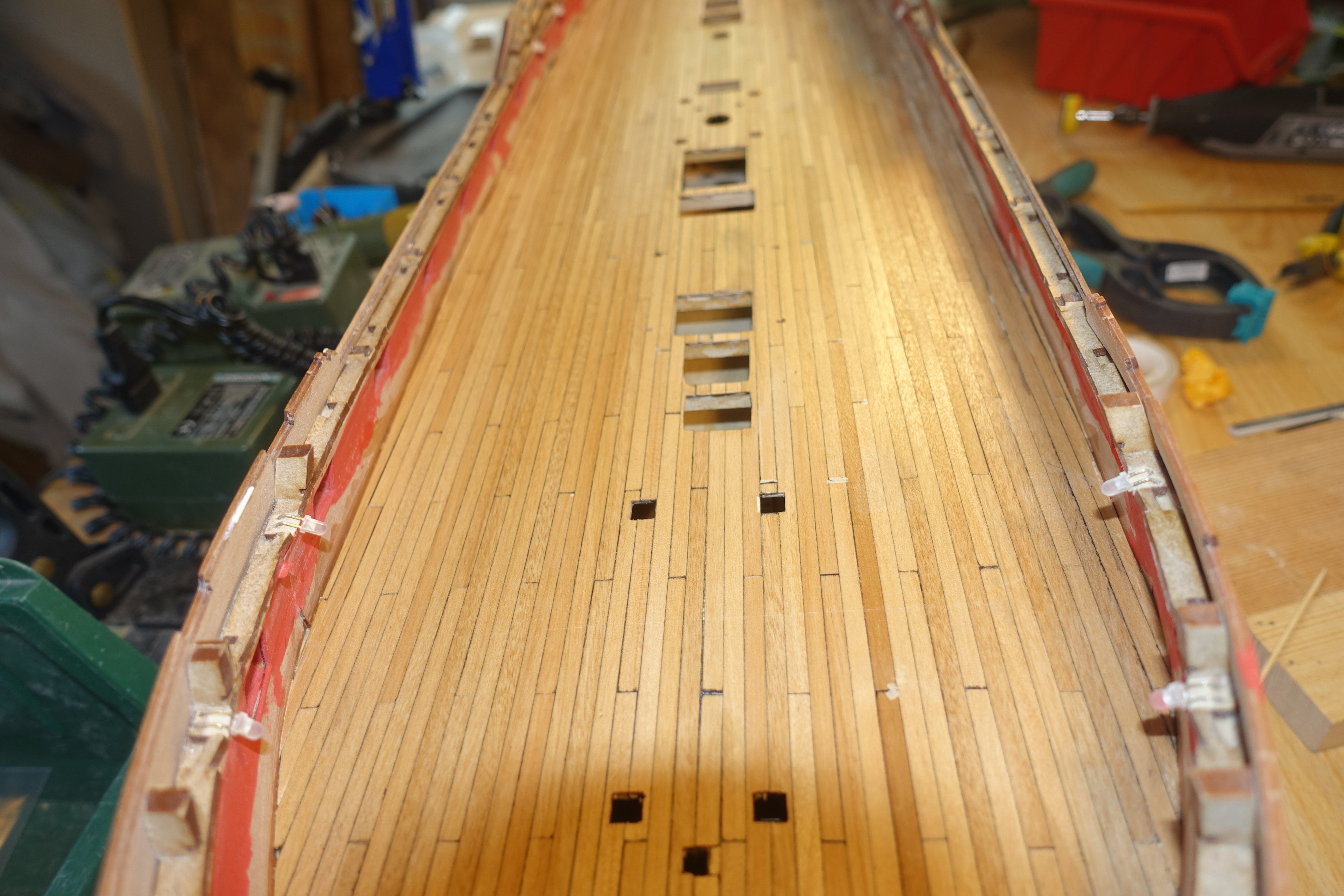
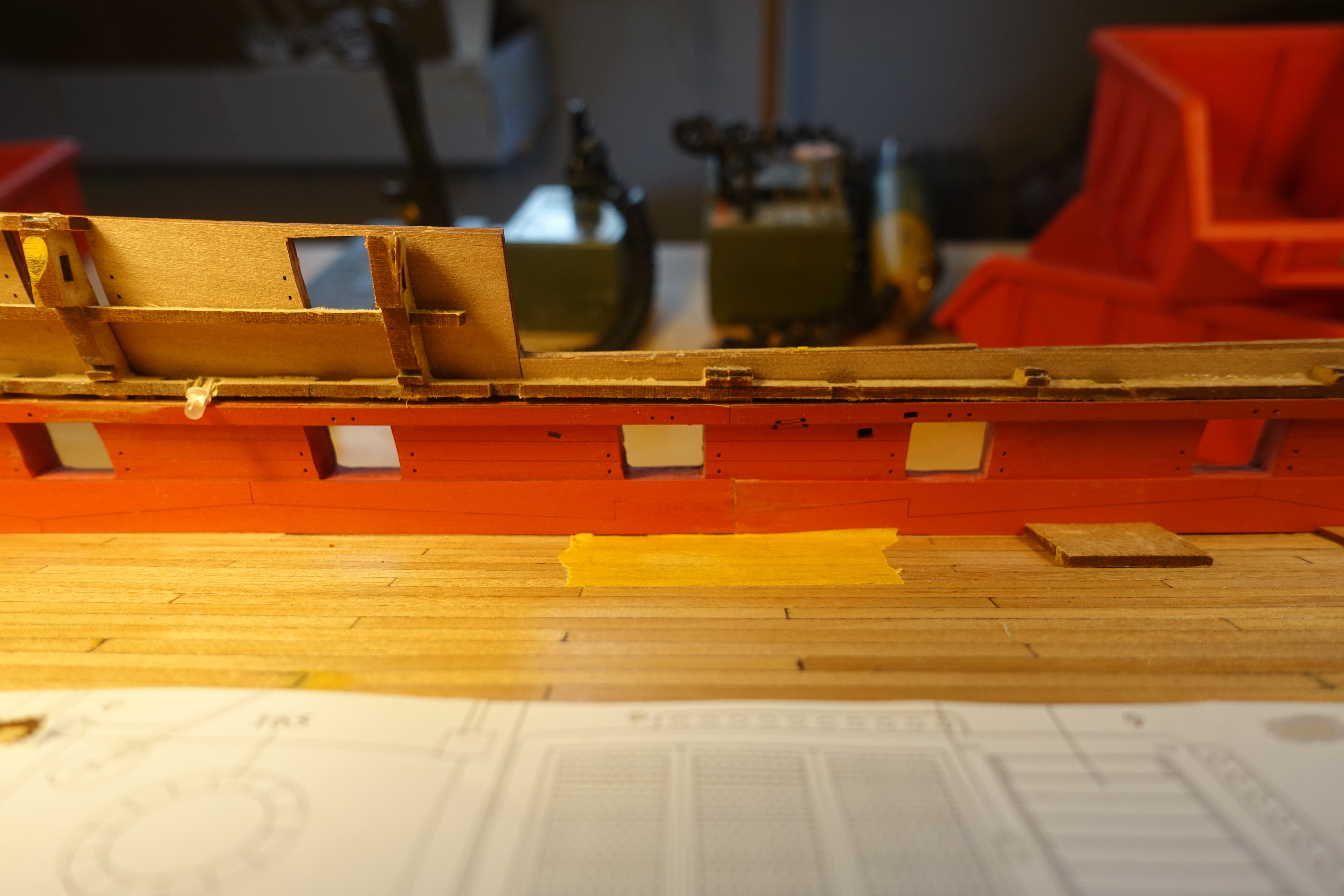
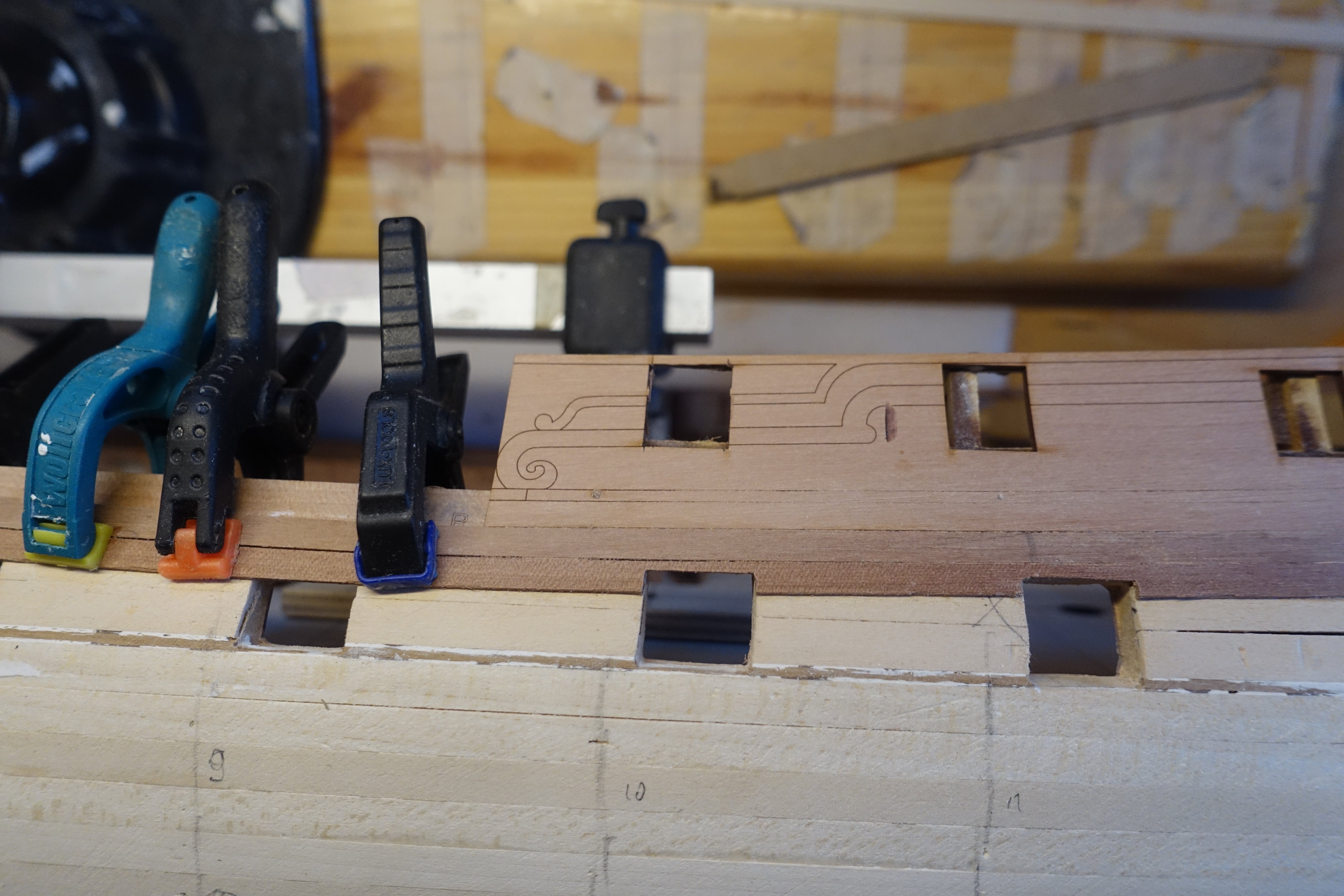
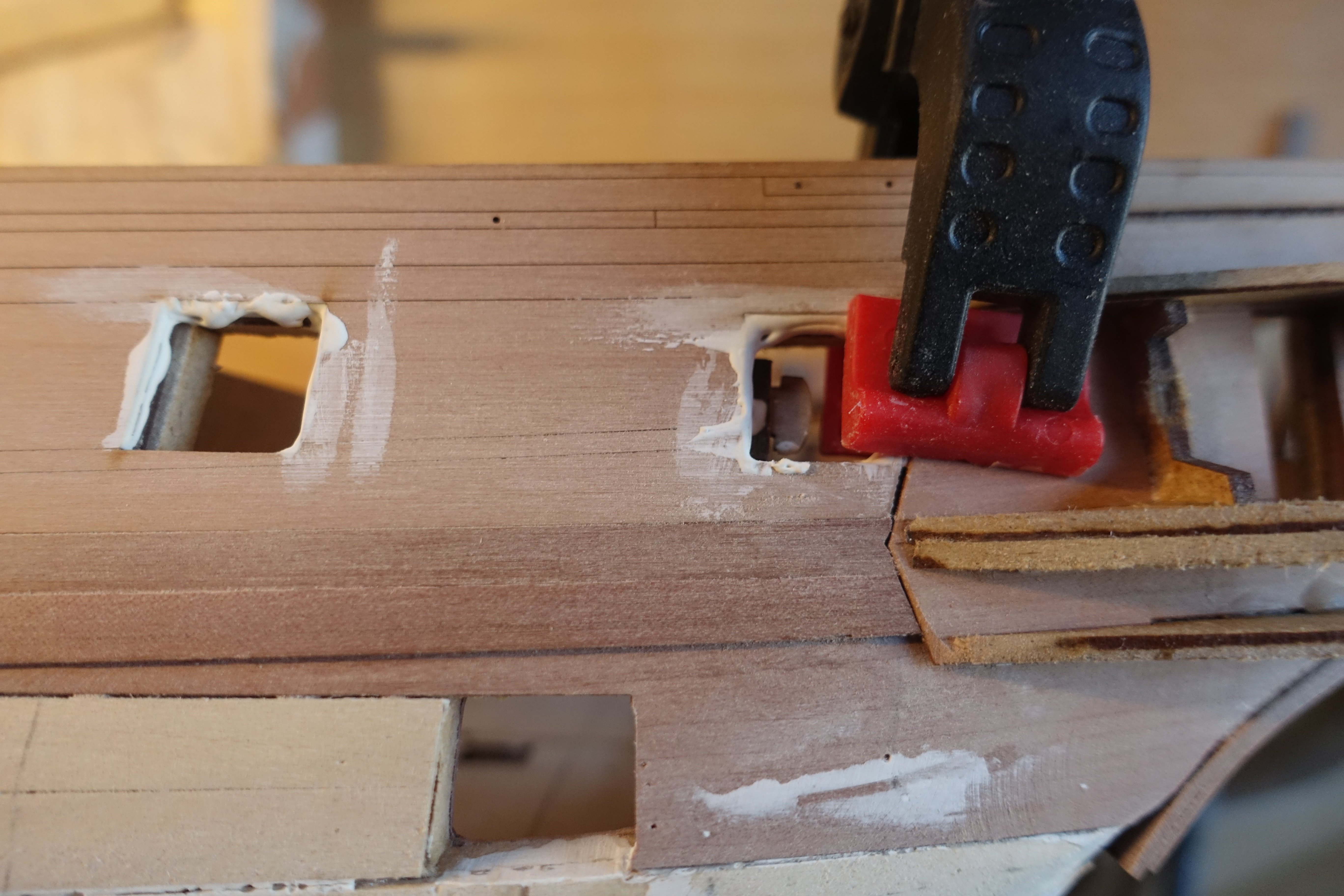
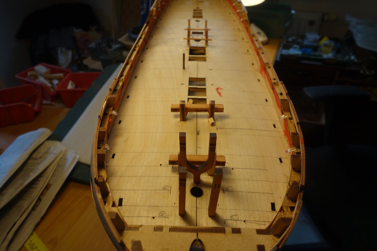
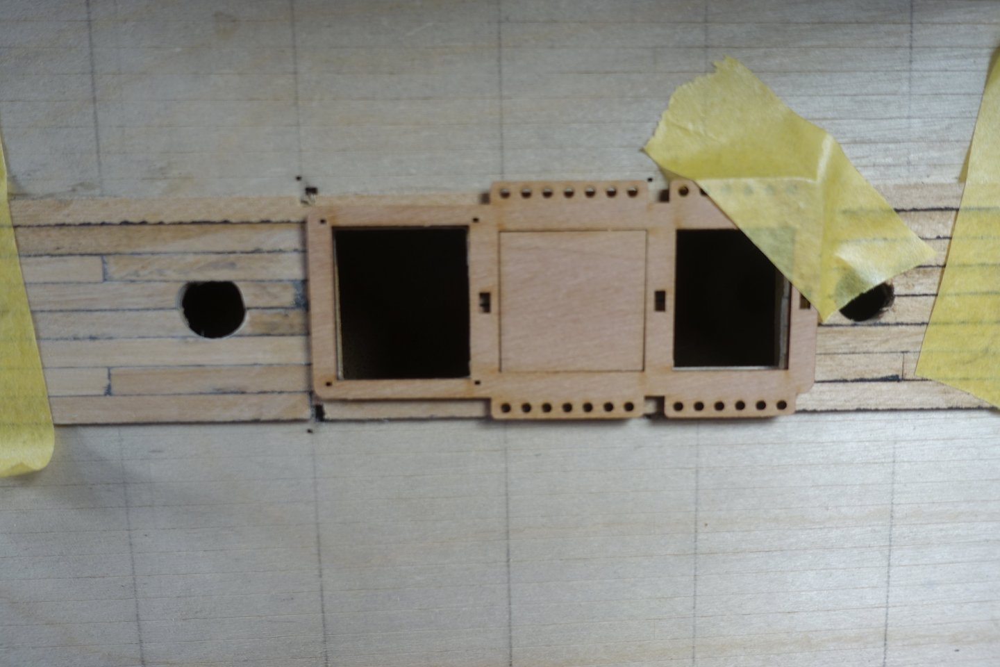
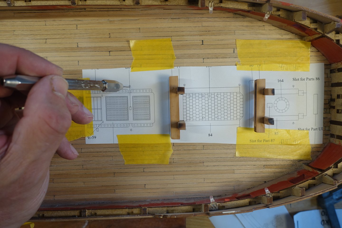
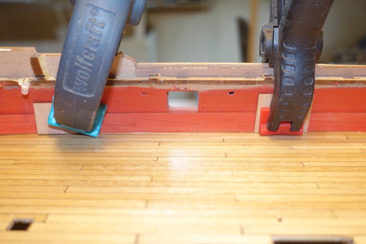
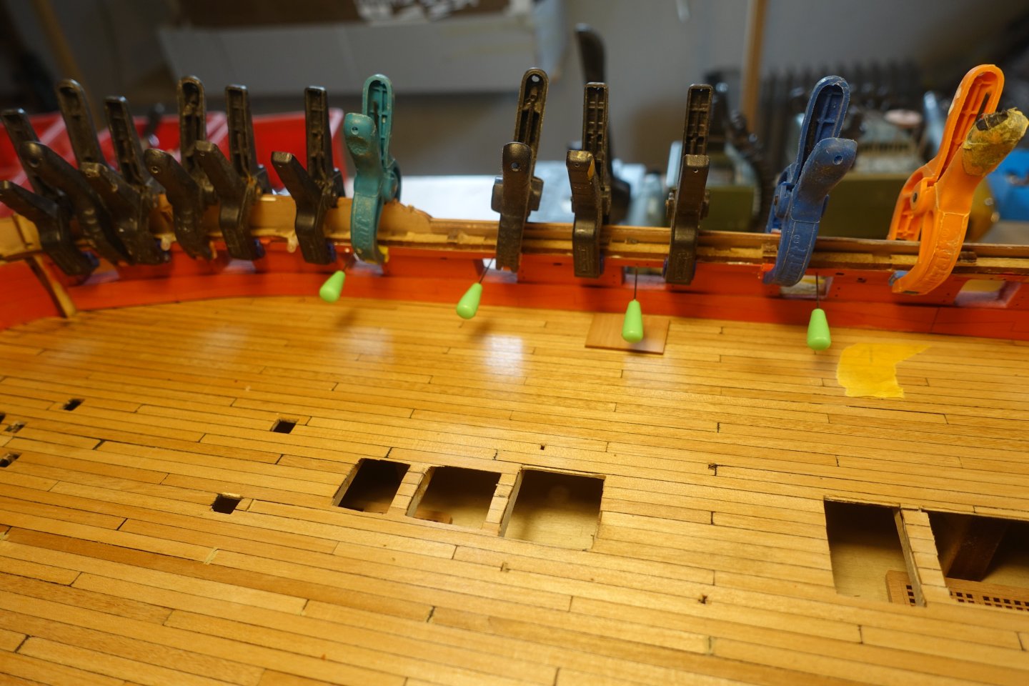
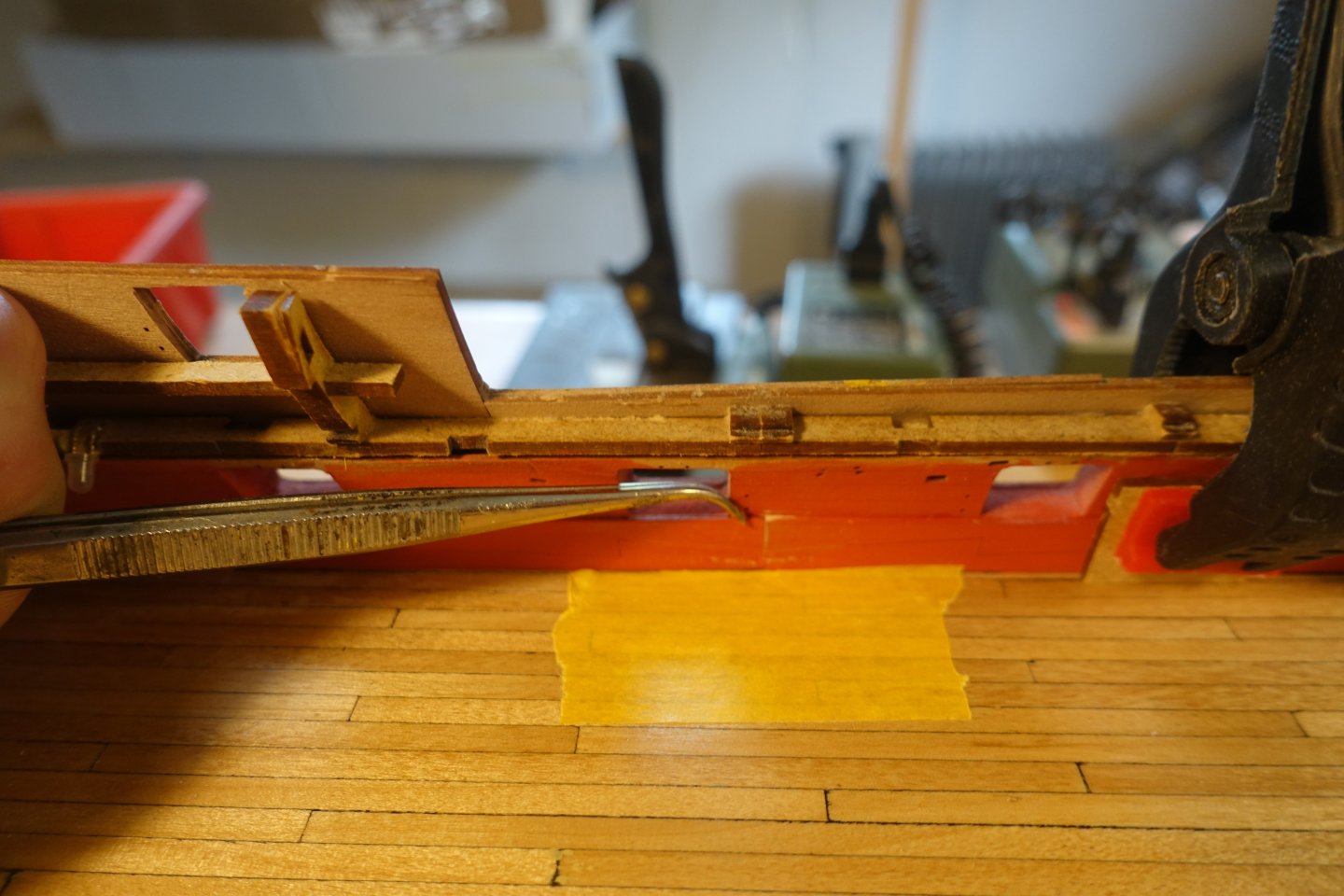
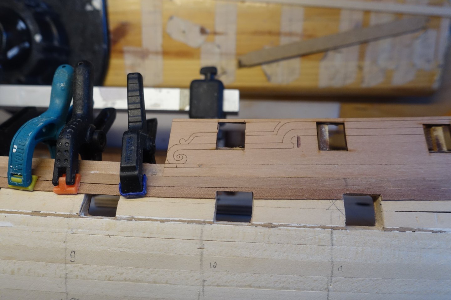
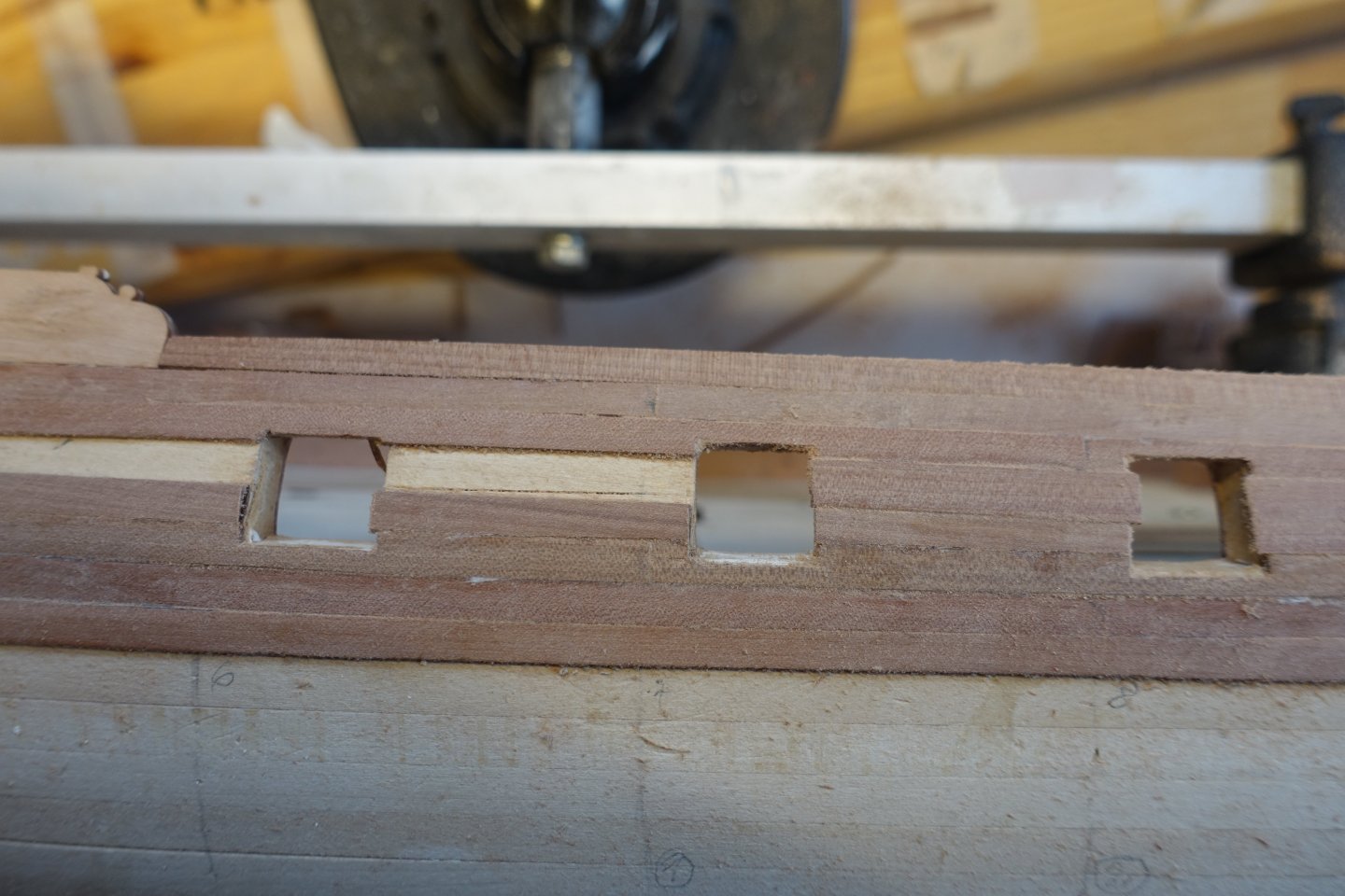
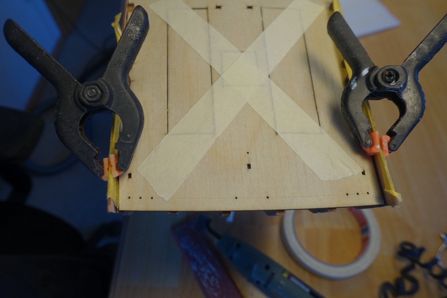
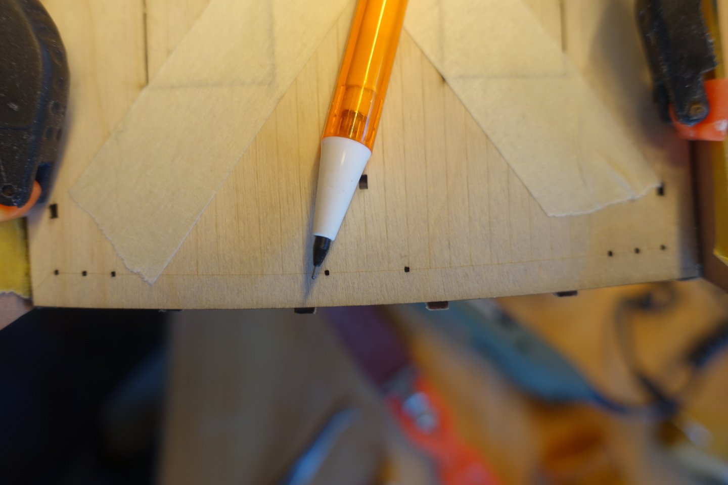
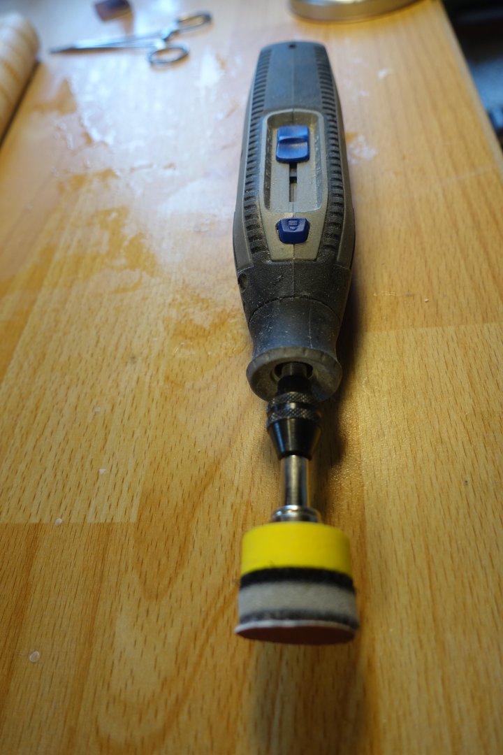
Planking the gun deck Before planking, the transitions between the two parts of the inner bulwark were filled and sanded. The caulking of the deck planks was simulated with paint. To do this, 7 deck planks, each 12 cm long, were clamped together. The spirketting and upper strip were painted five times with heavily diluted paint so that the engraved lines were still visible. The inner bulwark was also painted with diluted paint and the openings for the deck fittings were tested. No regrinding necessary. Some gaps approx. 0.2 mm. These will be bridged by the planking. Then I went on with the planking. In the middle area, where the base for the oven will be positioned later, i.e. an area that will not be visible, I sanded with 120 grit sandpaper and tried out the coating. I will first apply wood wax and then cover it with matt varnish. In the picture, you can also see that there is a larger gap between two strips. Thankfully, this is the only one and is not a problem, as the base of the oven will go here. The holes for the eyebolts of the cannon rigging were drilled using a template. The deck was sanded manually (120, 180, 240 grade) and with a Dremel (320 grade) then treated three times with wood wax and then coated with diluted matt clear varnish. I was afraid that the spirketting would not be flush with the gun ports, but it was flush without me having to modify the strip. For the alignment of the upper strip, push pins were inserted through the holes for the eyelet bolts. The alignment of the holes in the strip matches the arrangement of the holes in the bulwark below. The small gap between the two parts of the spirketting was filled with diluted filler, sanded down and then painted over. Next, I will turn my attention to the cannons.


-
Would also be interested in 1:64 scale
-
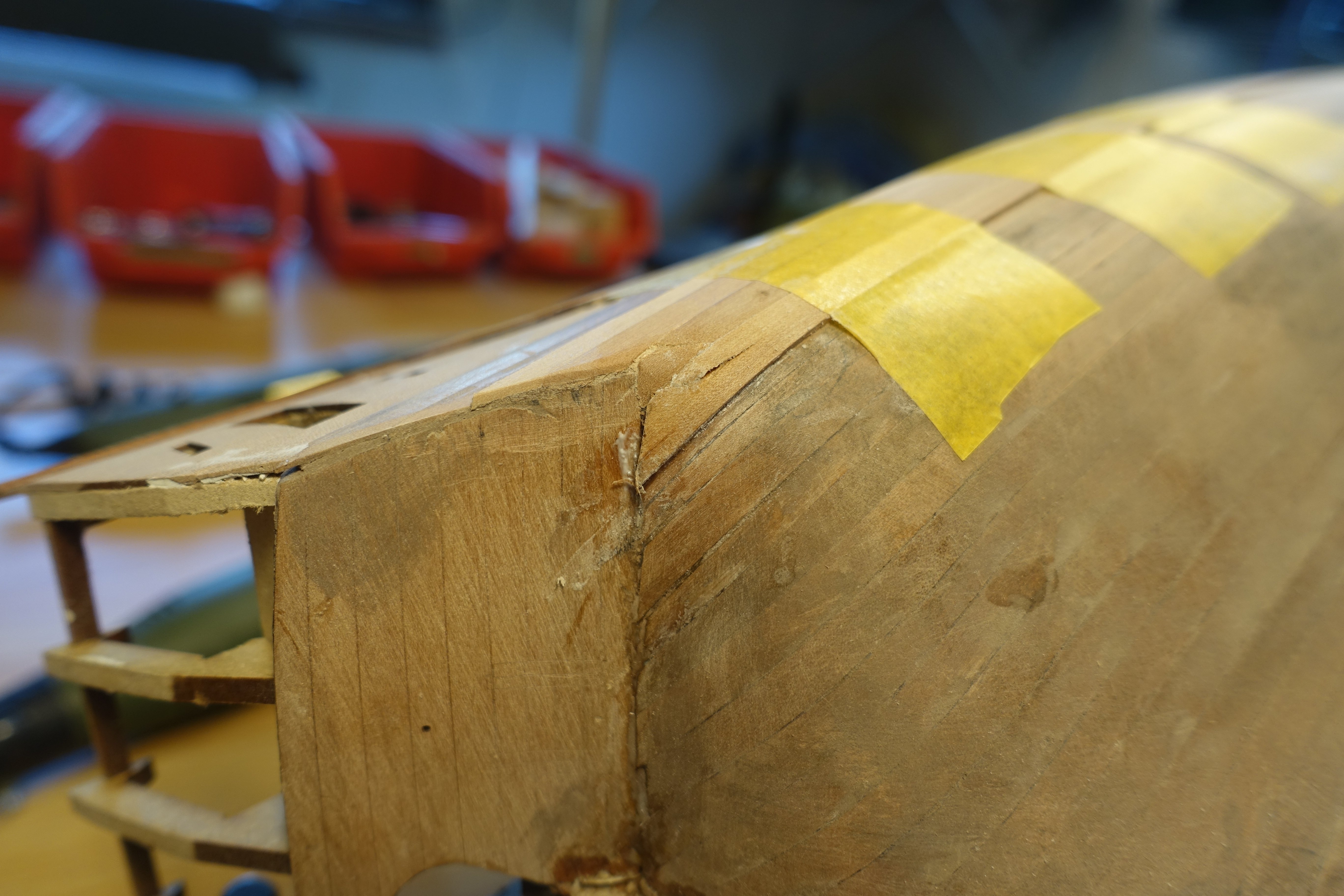
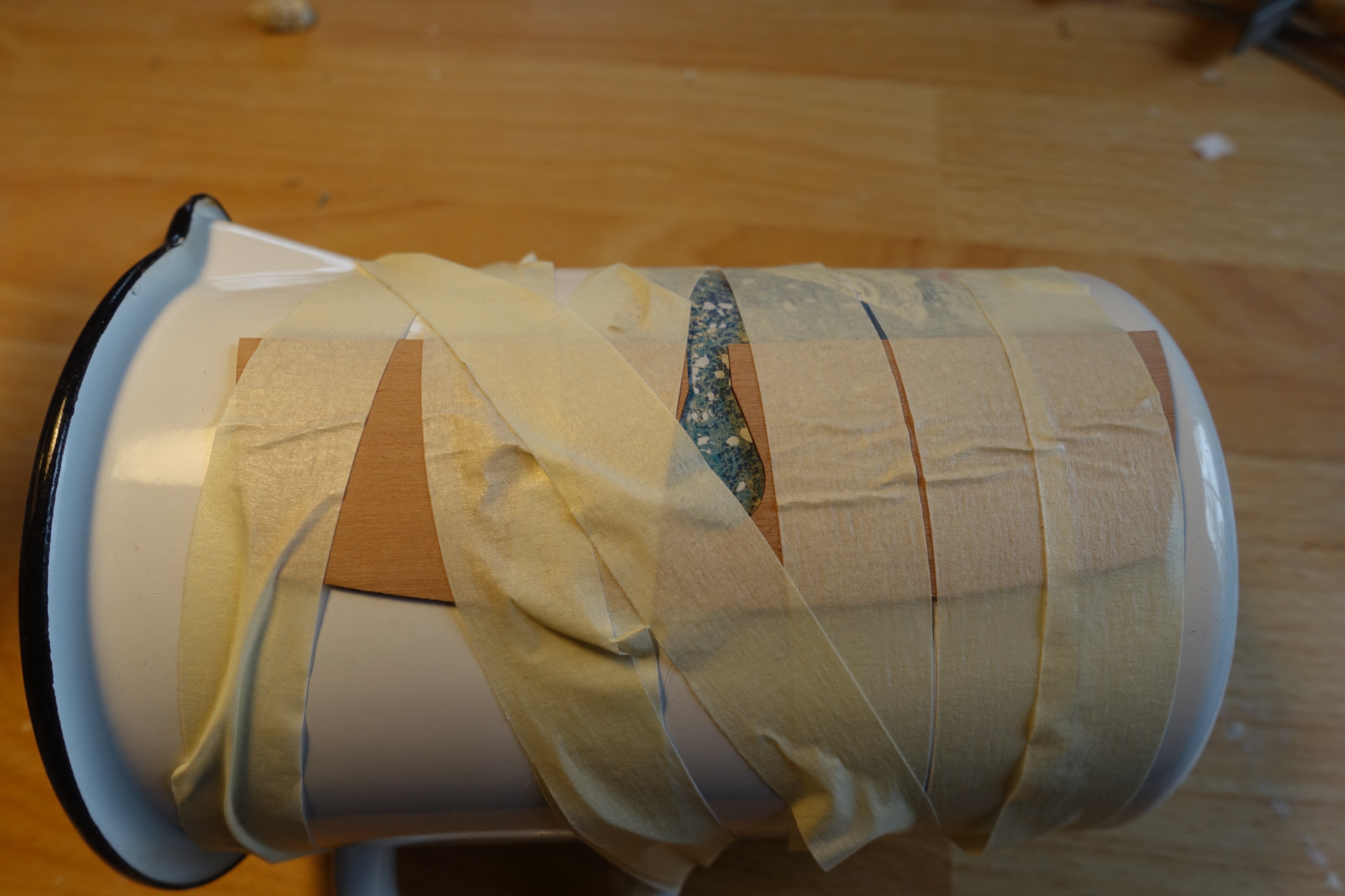
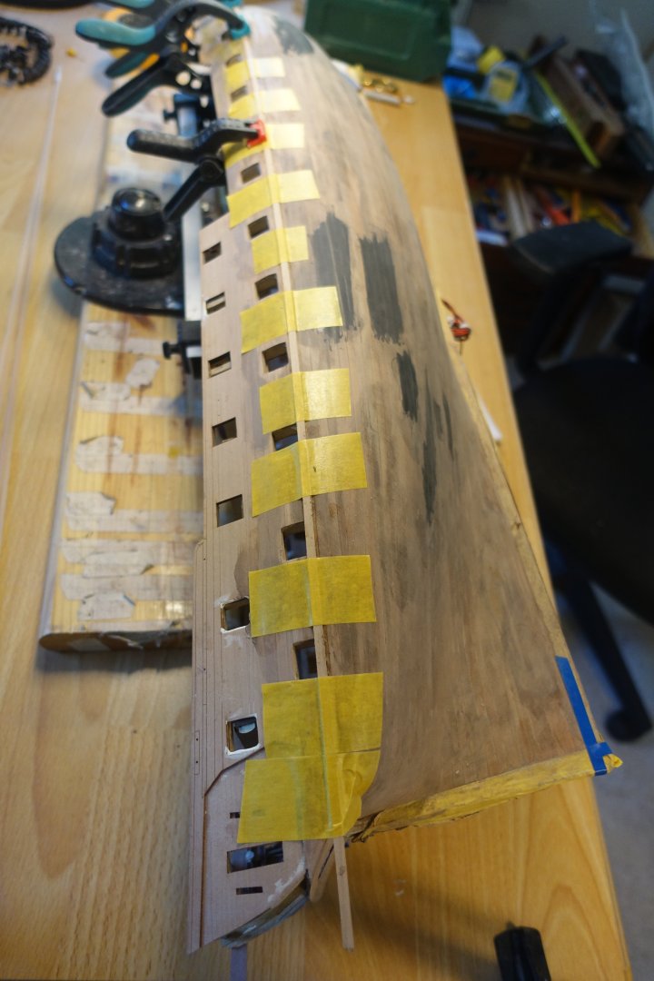
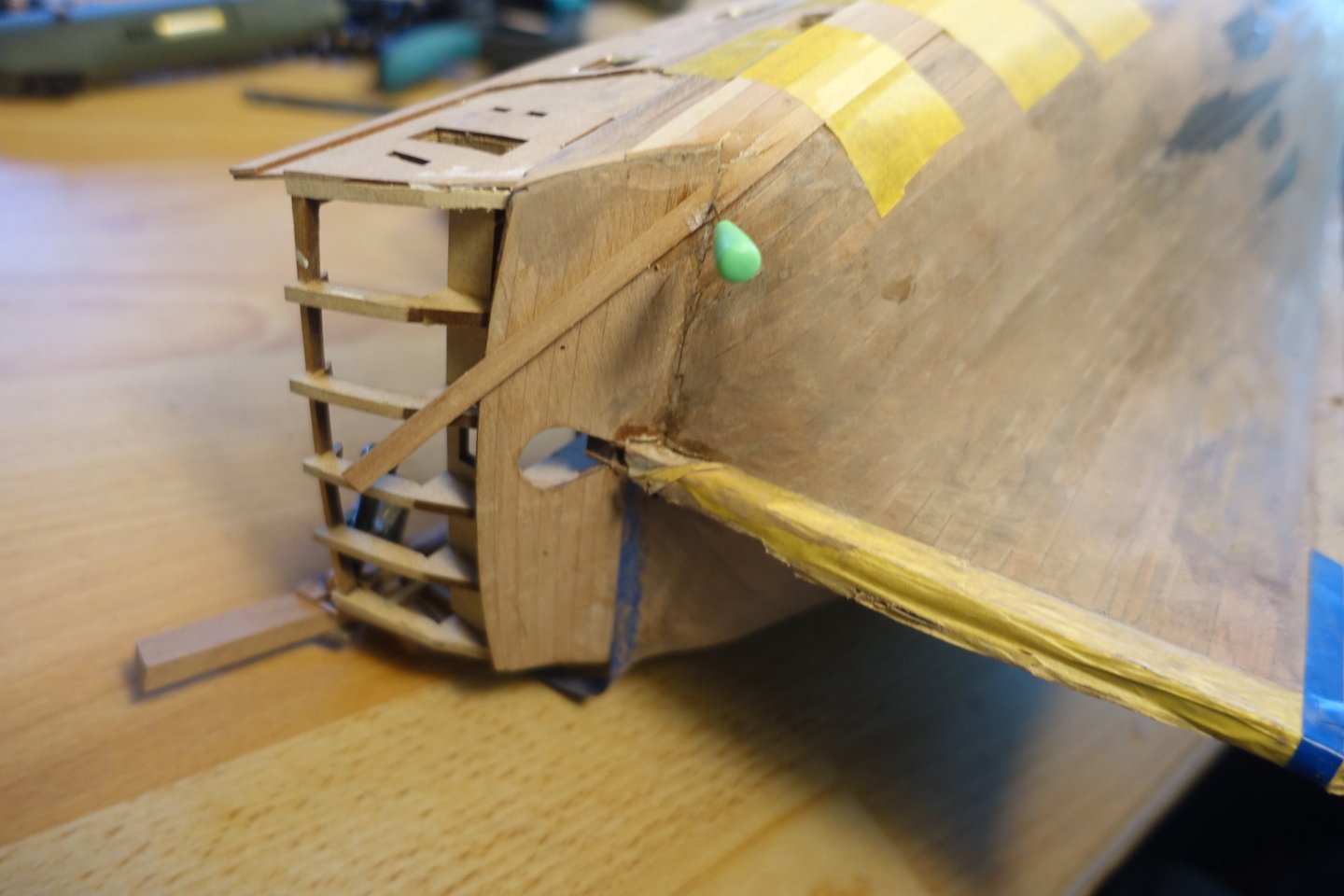
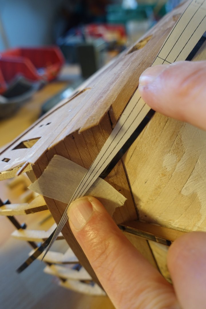
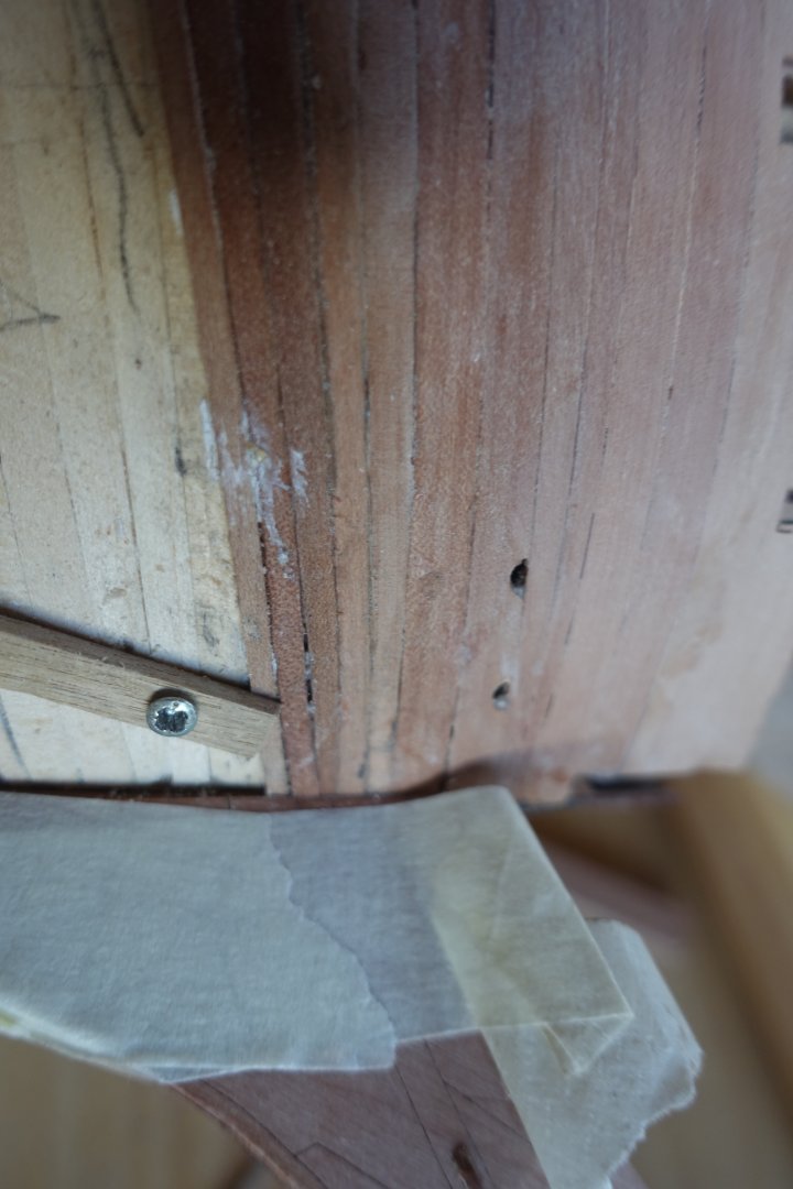
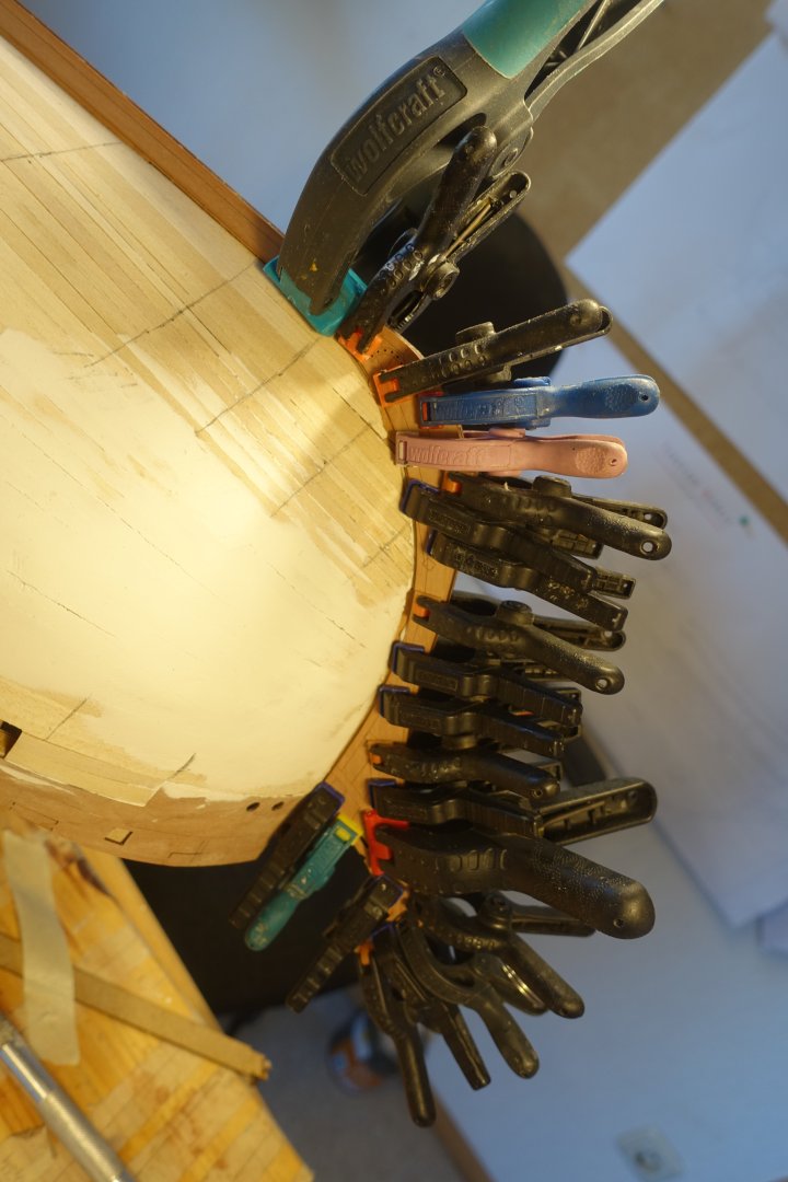
Attaching the wales The first 4 mm wide strip for the wale is very flexible and can be easily fixed with masking tape. I followed the guide strip of the second planking that I had attached earlier. When attaching the other strips, I was initially unsure how they should run in the stern area. In the end, I adjusted them to the curves of the second planking and then taped them towards the counter. The counter was slightly damaged in the process. I will probably fill this in before painting. Otherwise, the strips are very close together, so I won't be filling them, and I don't think it would be a problem if the planking is slightly visible. The wale was sanded with 180, 320 and 500 grit sandpaper.

-
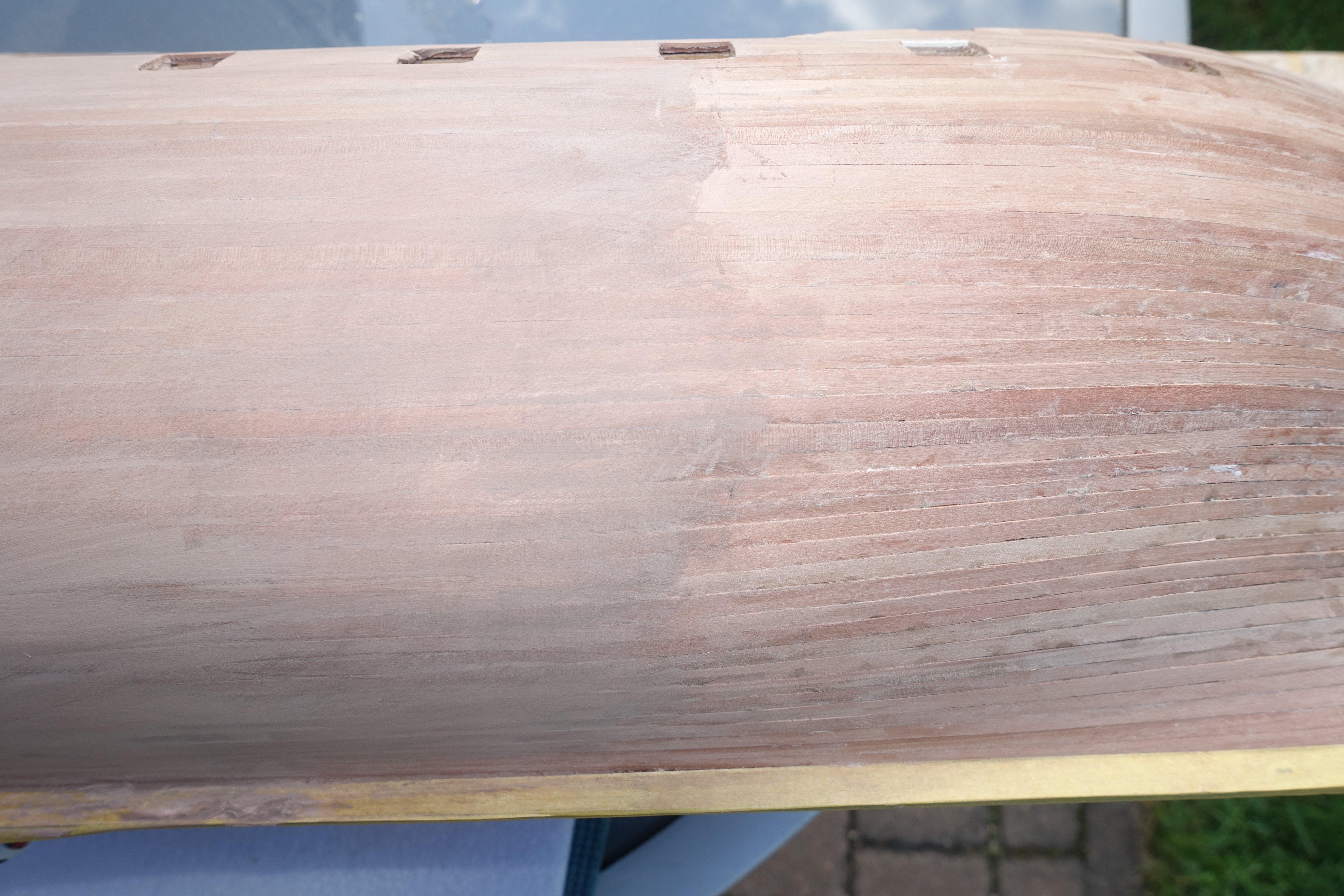
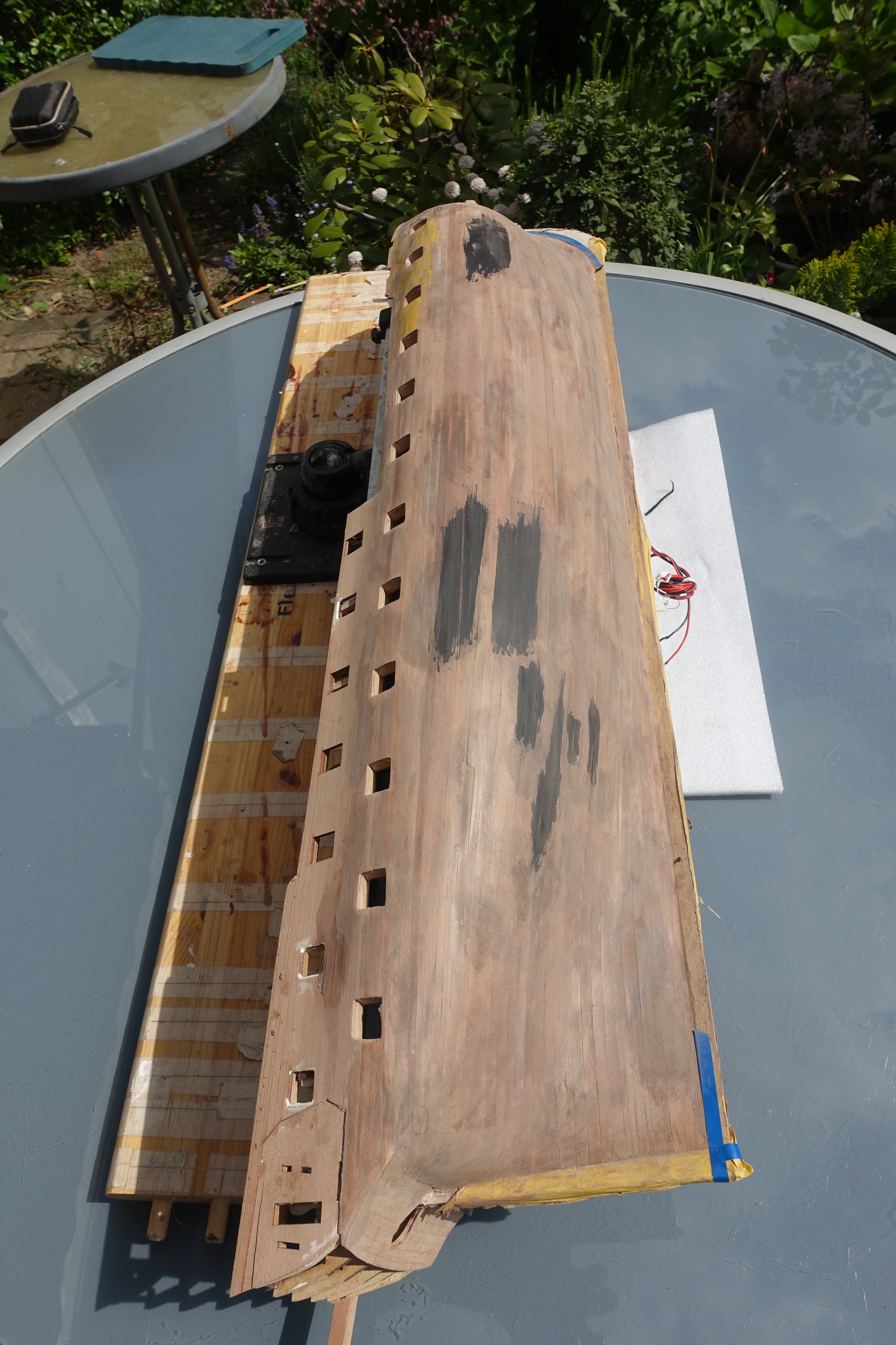
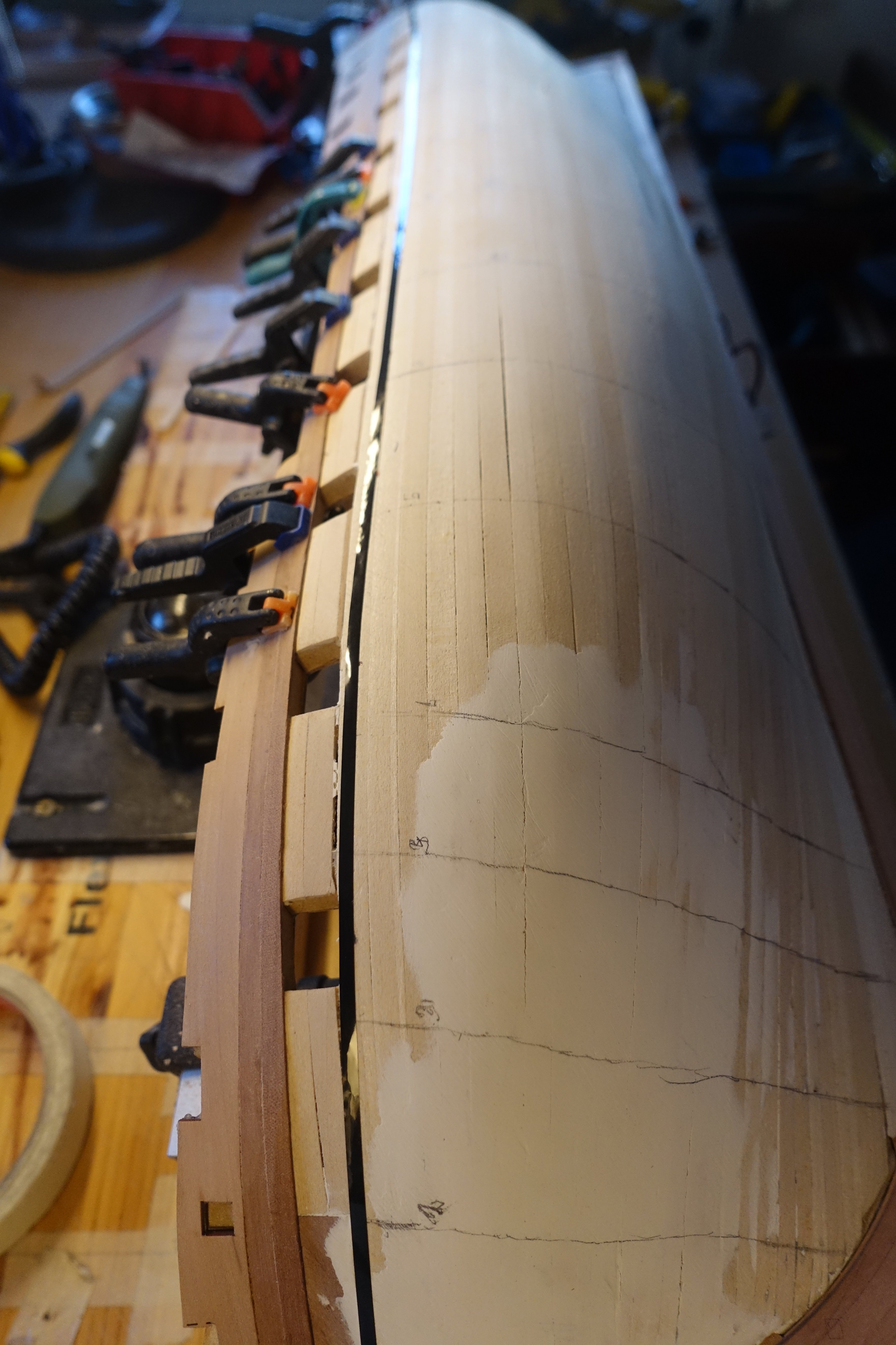
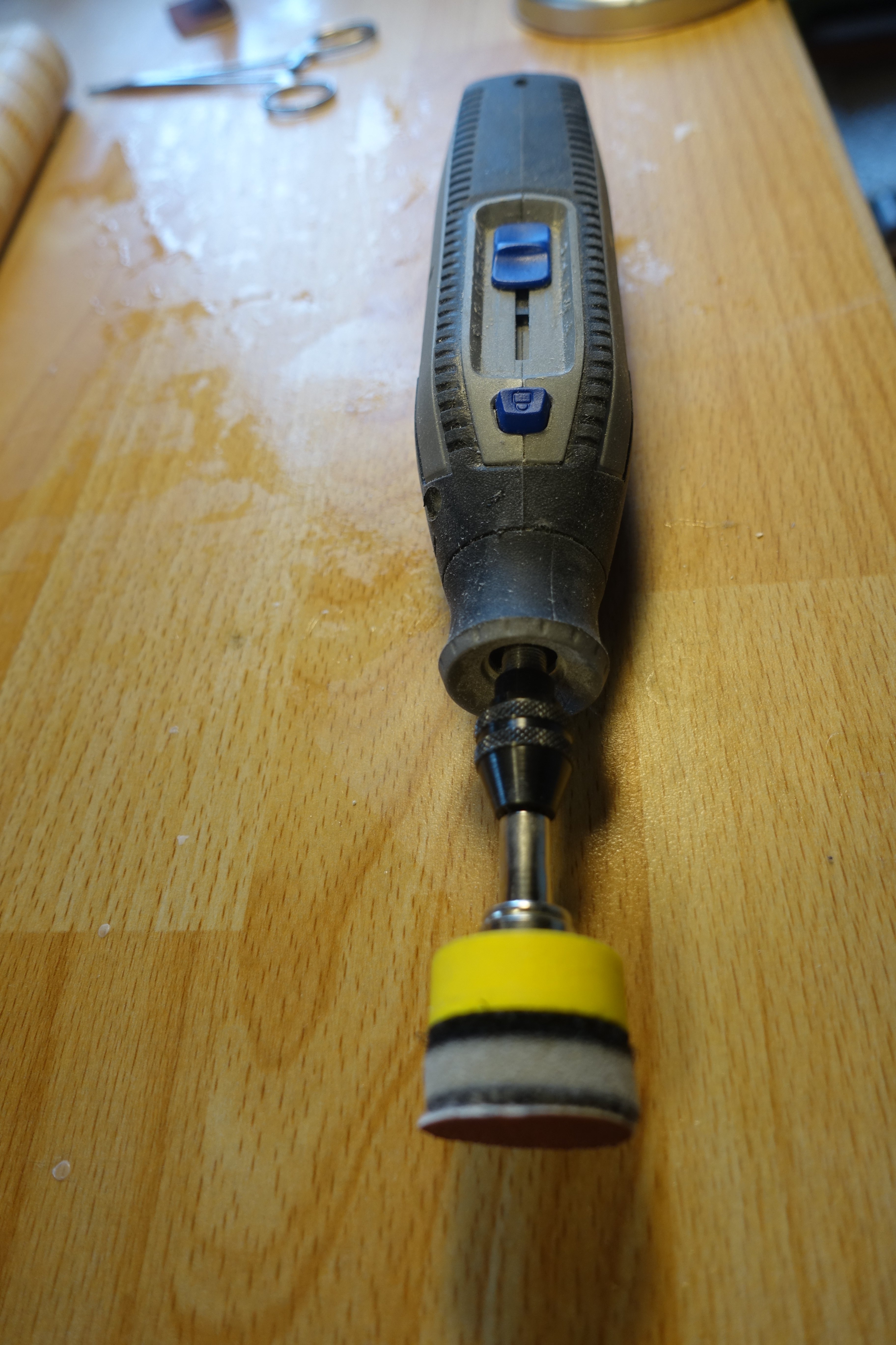
Sanding the hull First, the hull was sanded with 120 grit. Left in the picture: sanded. Right: unsanded. The hull was then filled and sanded again with 120 grit. Left in the picture: filled and sanded. Right: sanded. Filling and sanding was repeated several times. After sanding with 120 grit, I sanded with 240 and 320 grit. I also applied a thin coat of paint in some places to check how the plank transitions would look. Clark

-
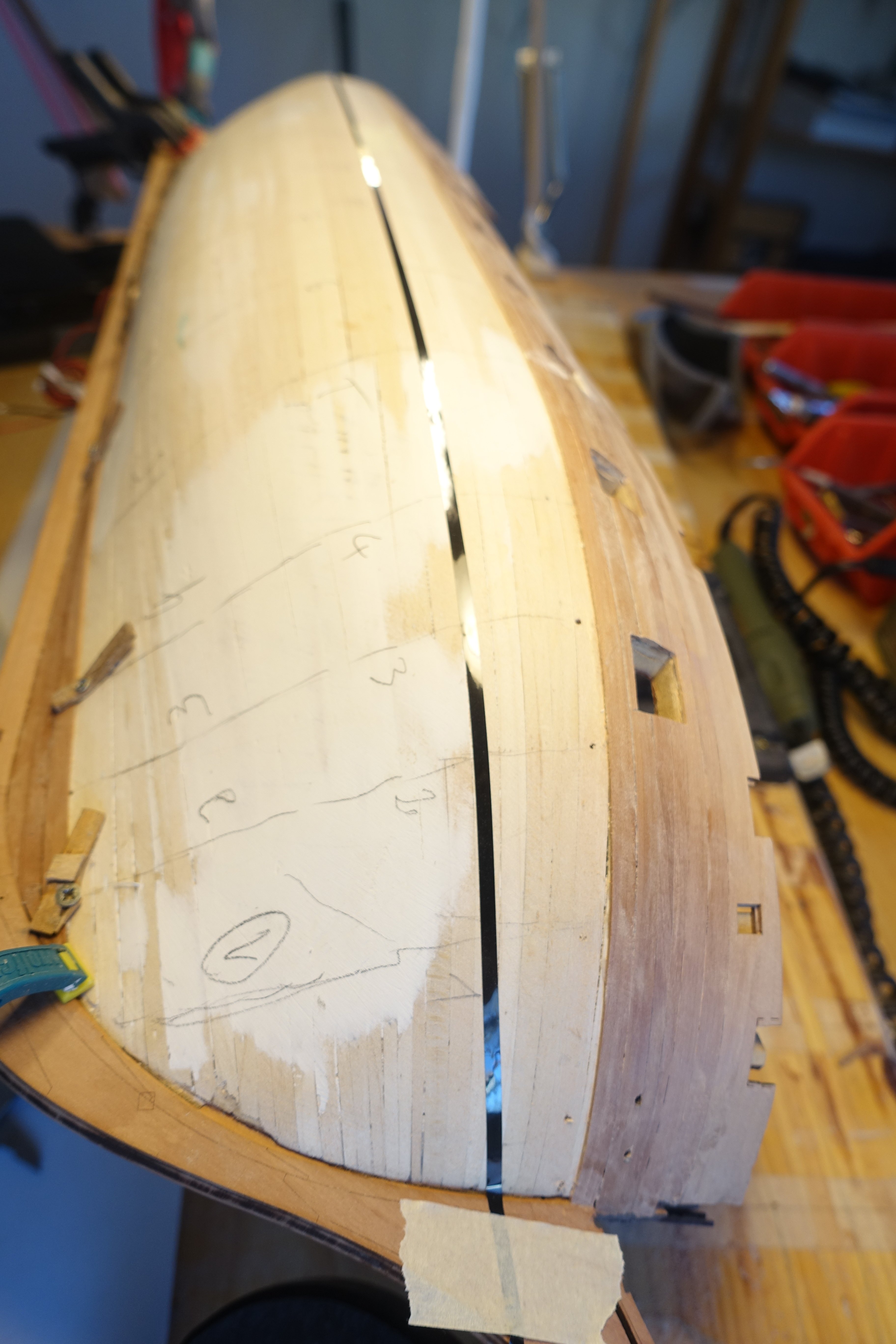
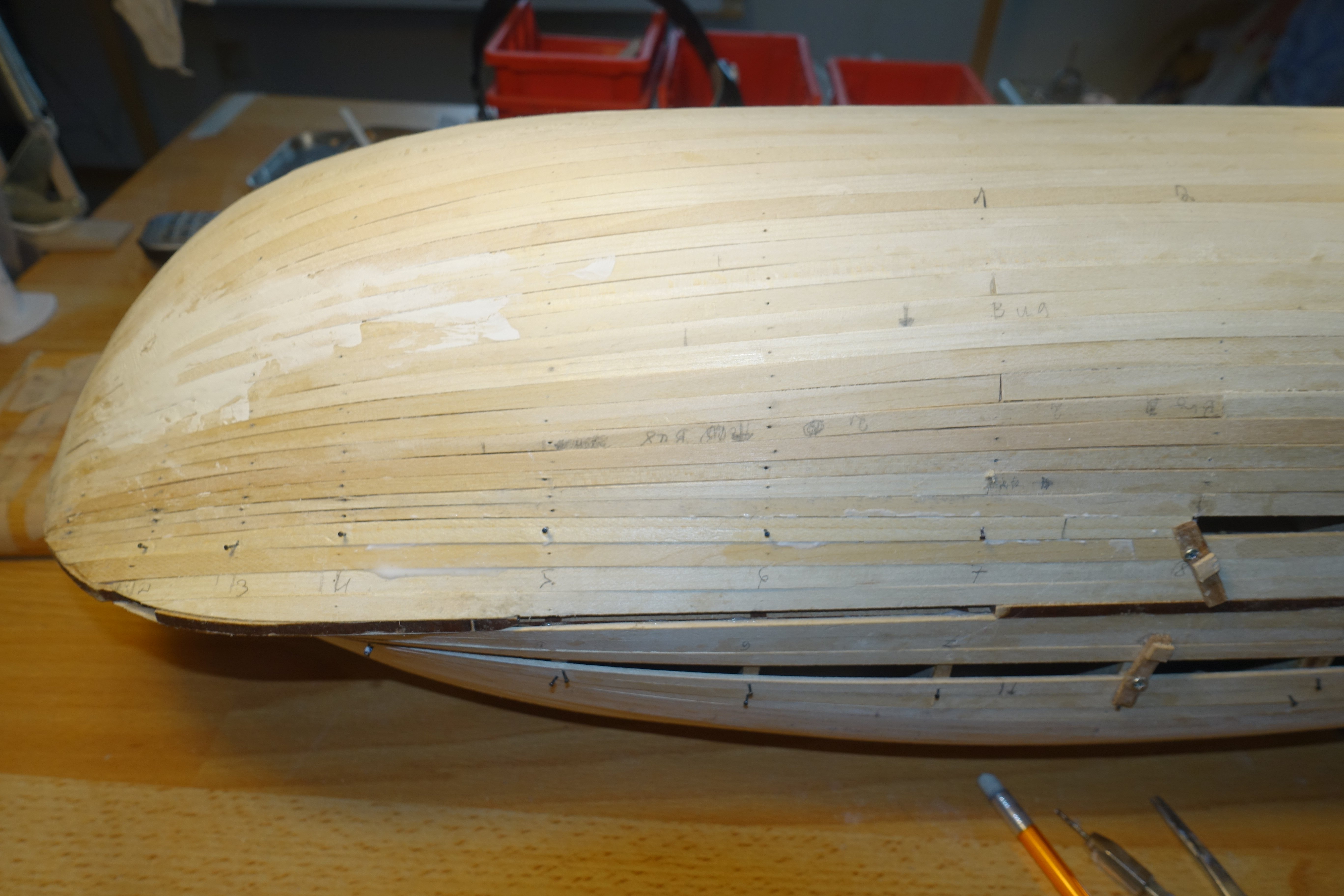
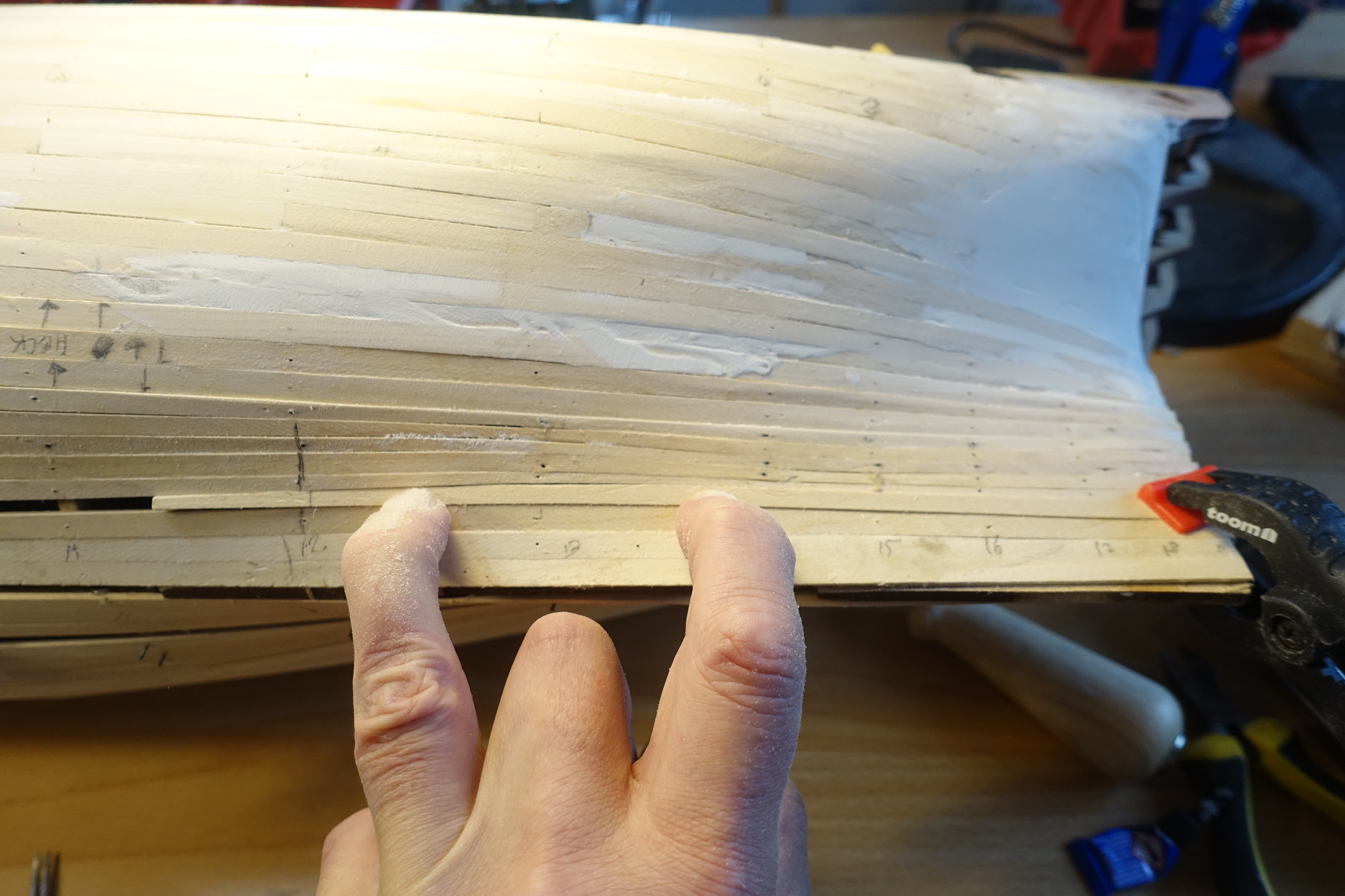
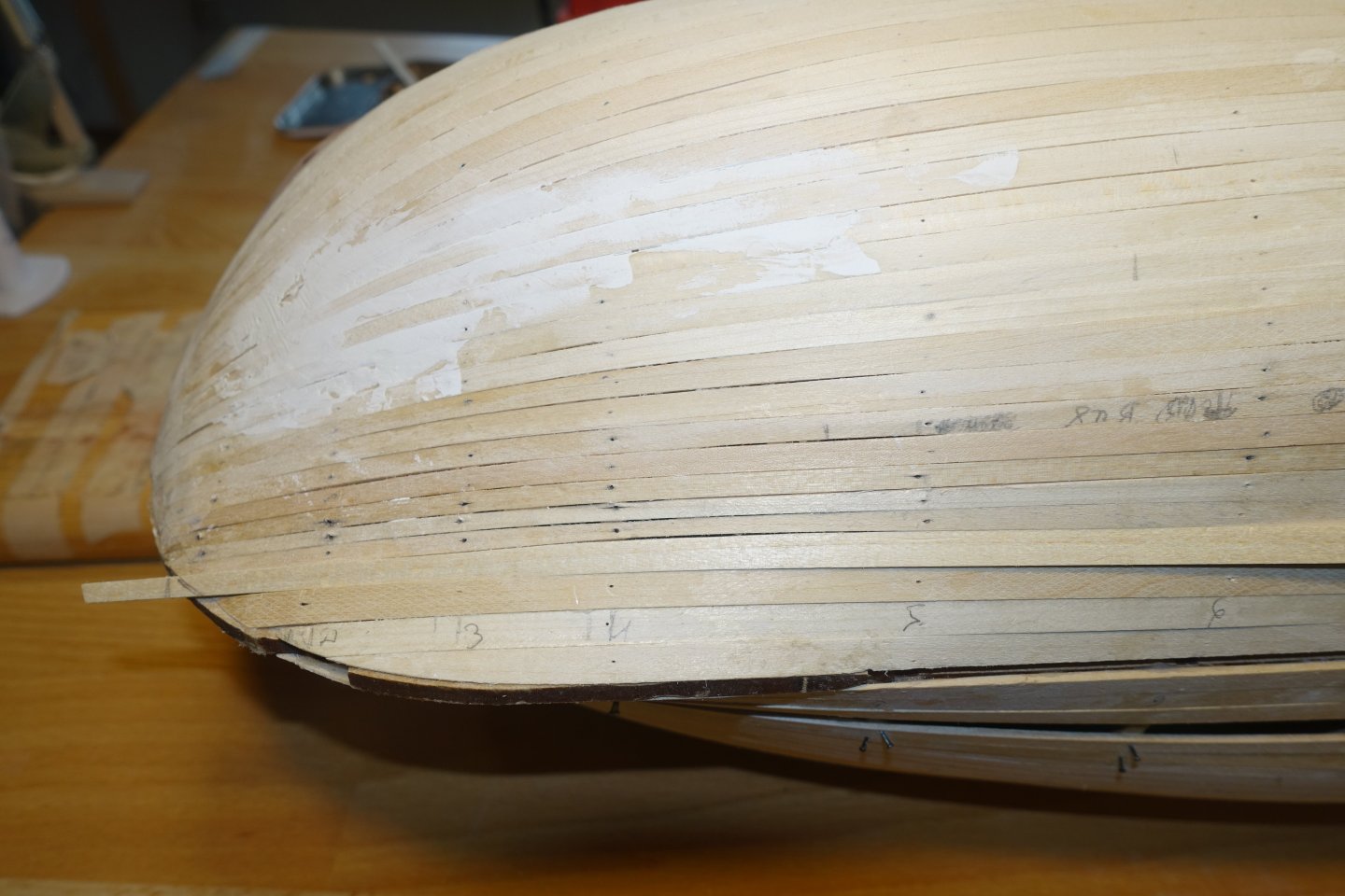
Finishing the 2nd planking It took some time to finish the second planking. The next 5 planks were fitted with small stealers at the stern. The distances between the garboard plank and the last plank laid were measured again. It is clear that a taper towards the stern is necessary from about the 12th/13th frame. However, I initially added a few more planks without tapering. After further planks were added without tapering, the next planks in the stern area were tapered further. The last plank can simply be fitted in the bow area. You can see that the distance to the garboard plank widens in the area of the 12th frame. I will compensate for this with the last plank. The critical area points downwards and will not be visible later. Critical area after adding one more plank I have levelled out the gaps in the stern area with three plank sections. All in all, the hull still looks pretty scruffy. But I think that the imperfections will disappear when sanding.


-
I made the stunsail booms for the fore channel and also built the fastenings on the channel. However, the spars then protruded quite a bit into the room and also hindered the placement of the anchors. I don't know how people solved that problem back then. Inboard? Dismantled the spars again.
-
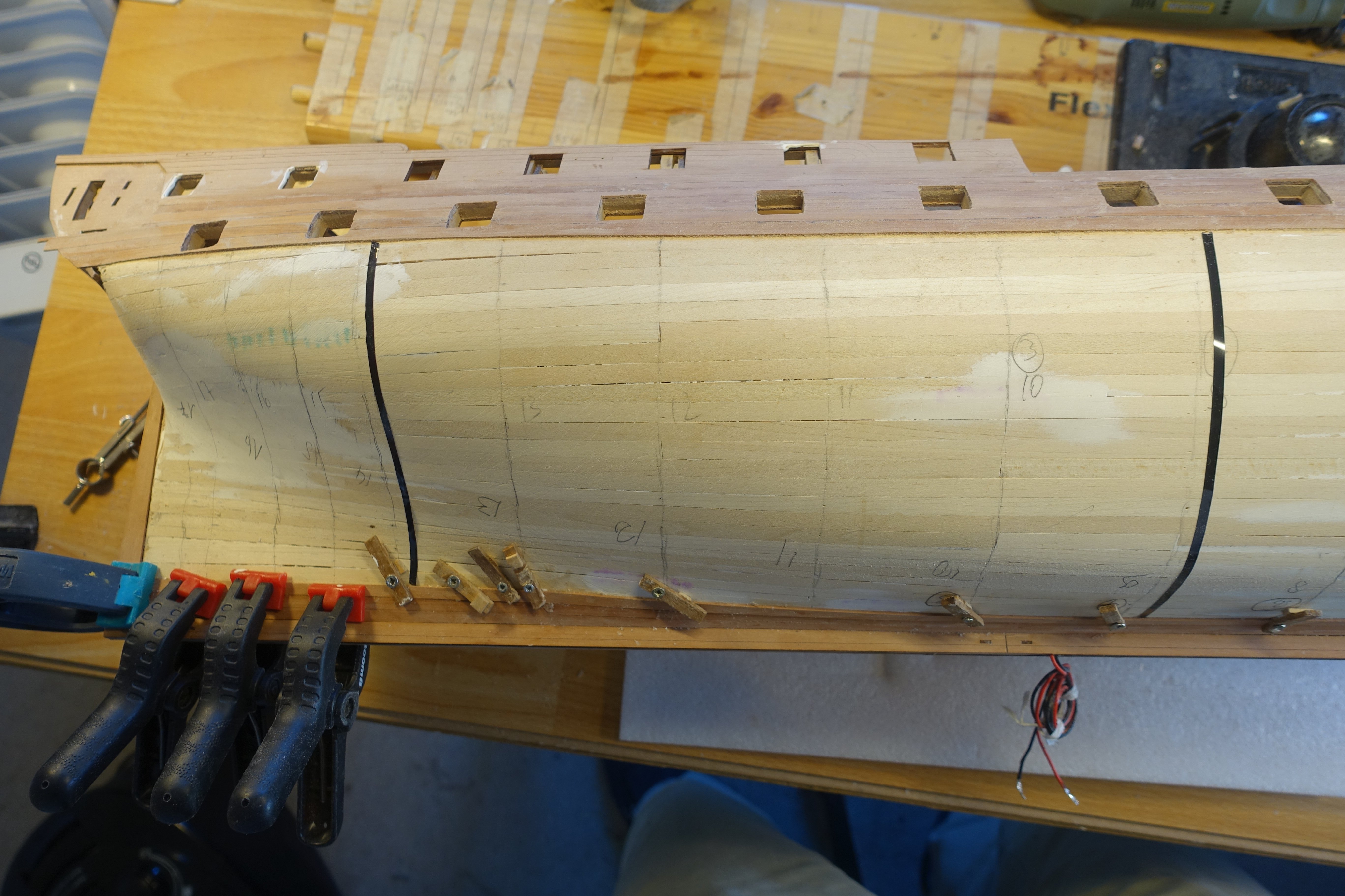
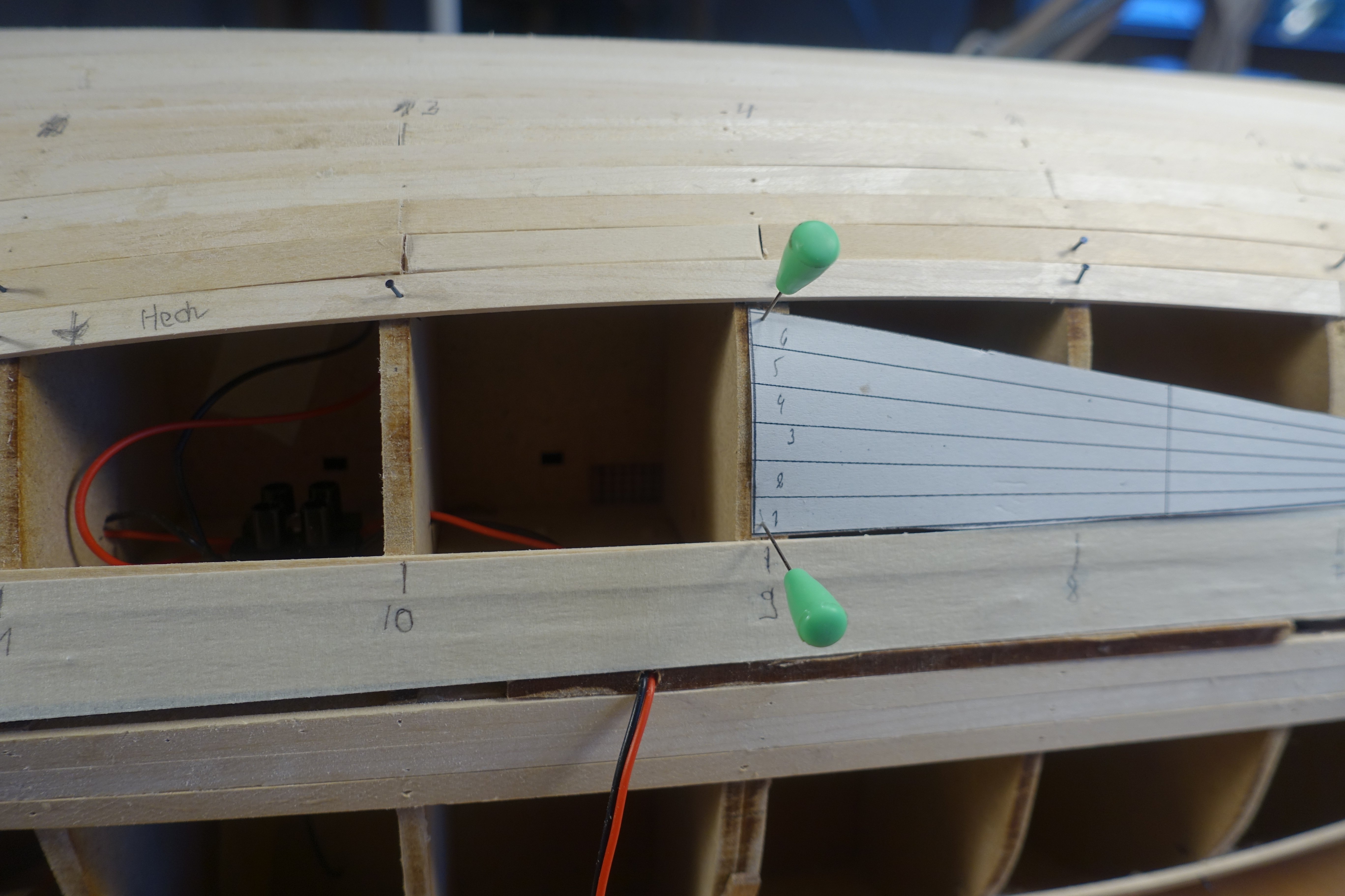
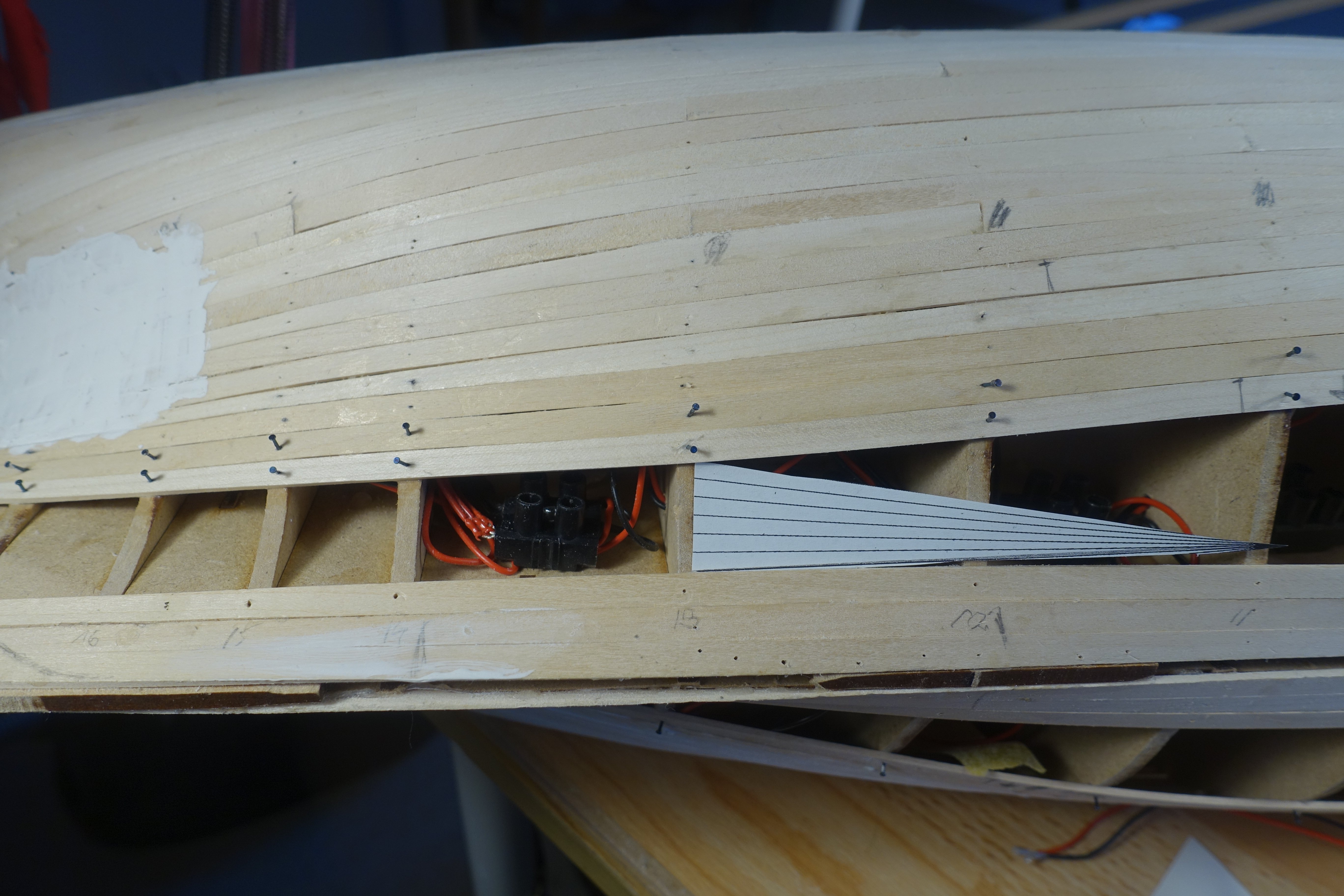
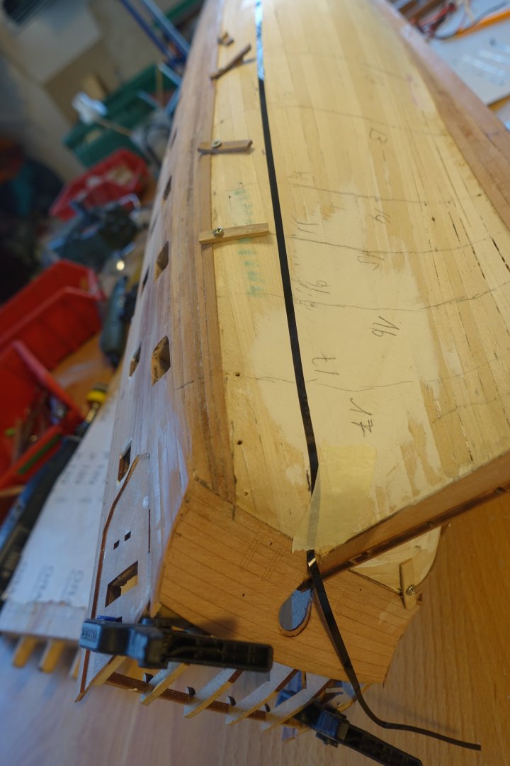
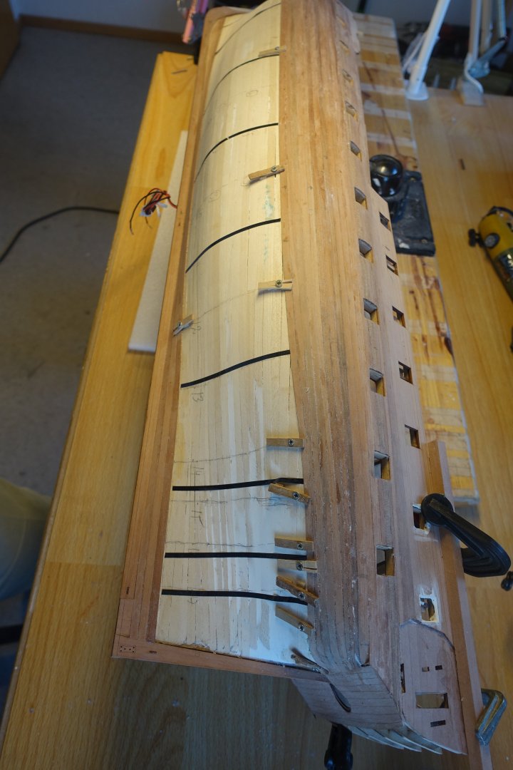
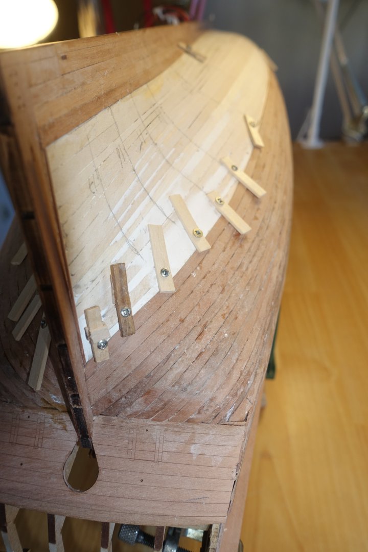
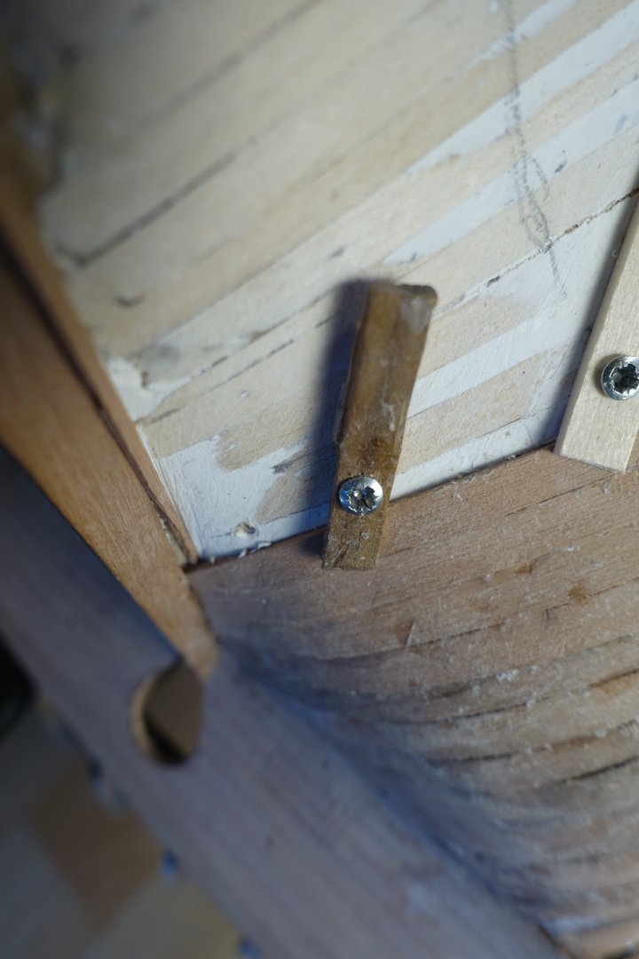
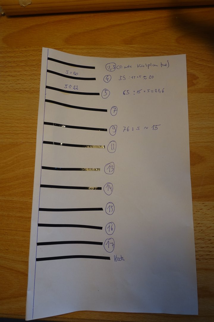
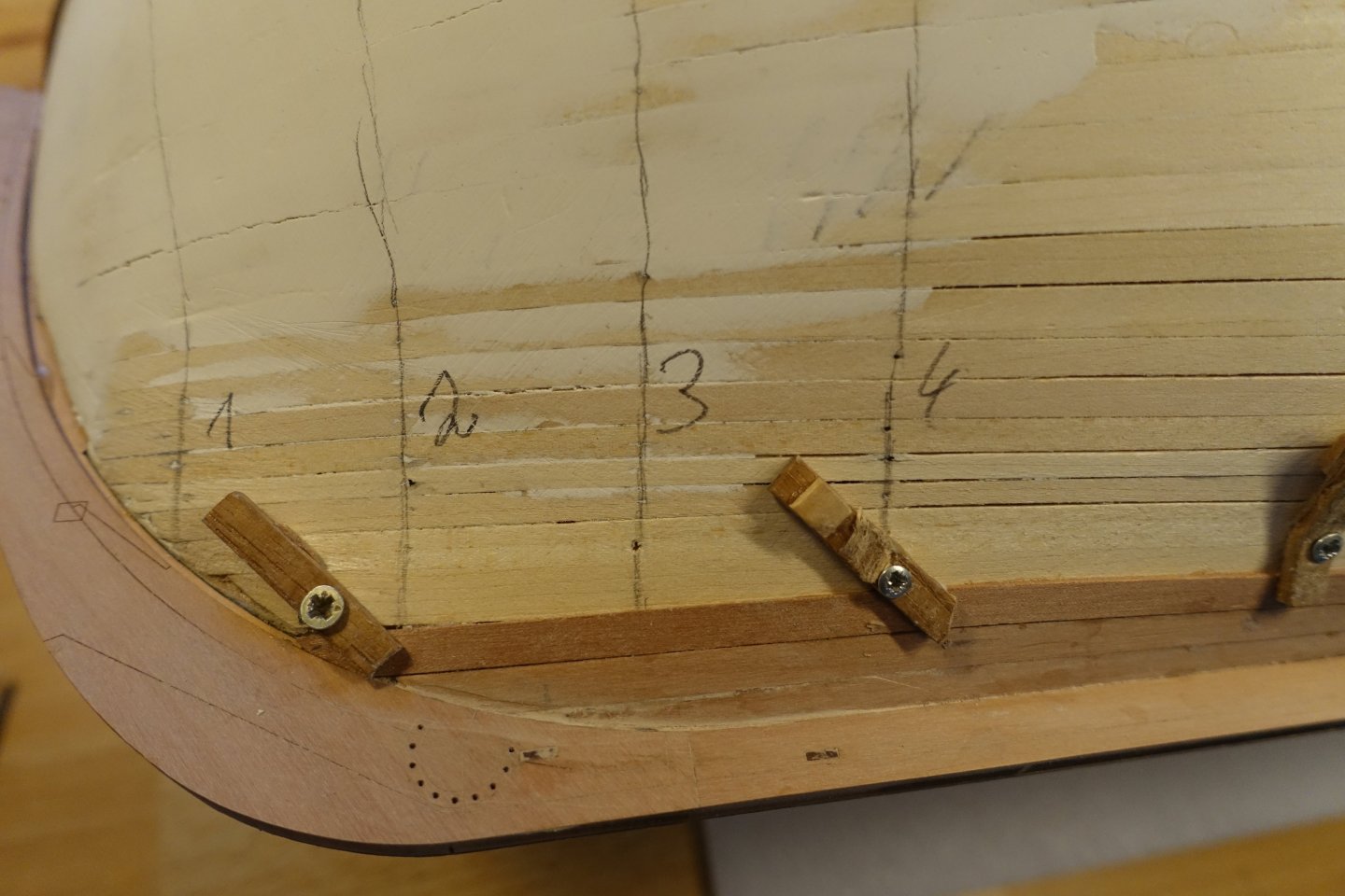
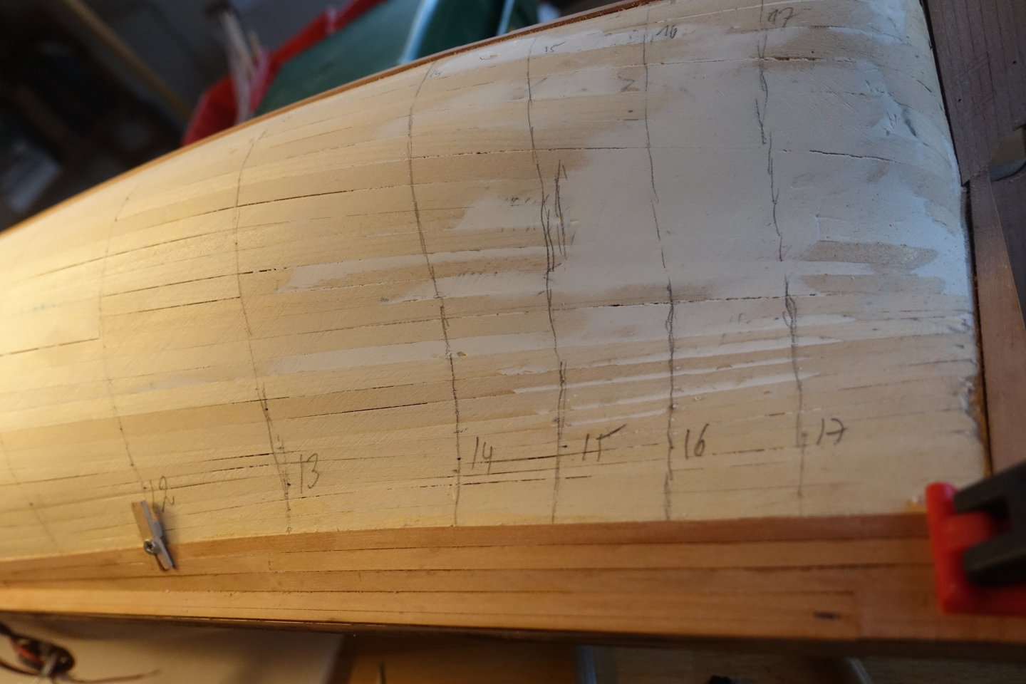
Just a short update: the second planking takes time. For the next five planks, the distances were measured at several bulkheads and, as described above, these distances were converted to five planks and corresponding marks were made for laying the marking tape. 5 planks are laid and for the next 5 planks the distances between the garboard plank and the last plank laid were measured again using marking tape and then recalculated. I will not be tapering the stern area, only the bow area. The distances converted for 5 planks were marked on the hull at the level of the 3rd, 5th and 9th bulkheads, and a marking tape was placed along these marks to record the taper up to the stem post. 5 more plank layers are applied in this way. At the rudder post, the rabbet was about 0.3 mm too large (too much of the first planking was sanded off). I then underlaid the planks at the rudder post with a thin strip. For the next five plank layers, I then again measured the distances between the last laid plank and the garboard plank at various bulkheads. Now the distance could also be measured at the rudder post. It can be seen that stealers may be necessary at the stern. I will wait and see how the planking develops. At the bow, I no longer use marking tape to determine the curve, but instead I use Chuck's planking fan to ‘calculate’ and mark the necessary tapers. To taper the planks correctly, I measured the bulkhead spacing again using painter's tape.


-
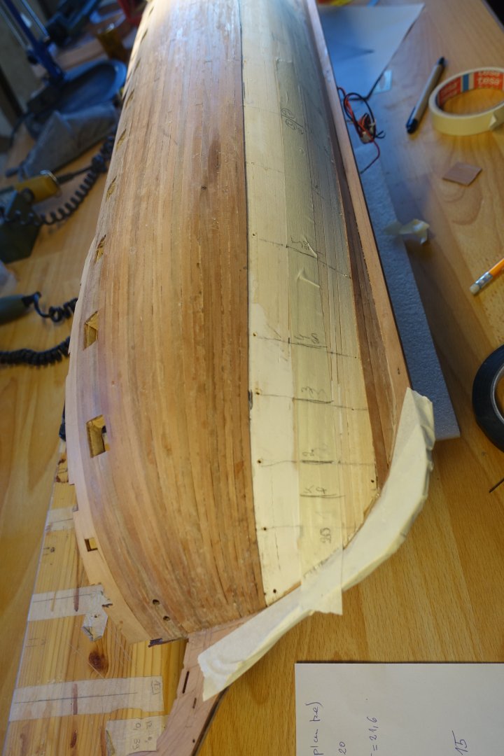
Planking the bulwark on the starboard side, planking the hull The bulwark on the starboard side was planked in the same way as the port side. It also took longer than I thought. To plank the hull further, the distances to the garboard plank were measured at bulkhead 9 and at bulkhead 14. During the first planking, it was found that the distance at bulkhead 14 was reduced. I will measure the plank tapers for every 5 planks. Therefore, the reduced distance at bulkhead 14 was calculated down to 5 planks (23.7 mm) and a corresponding mark was made on the hull. The only fixed points were marks at 25 mm for bulkheads 7 to 11 and the mark of 23.7 mm for bulkhead 14. Otherwise, the marking tape was laid by eye. As often discussed here, there are many ways to determine the plank tapers. I'm quite happy with mine. With Chuck's Planking Fan, the first two planks were only tapered at the bow. At the stern, one plank should still be in full contact with the counter and another full plank should form the transition from the counter to the hull. To form the transition from the counter to the hull, a plank was watered, adjusted and allowed to dry. The adjustment at the stern was also carried out wet for the other planks, and the planks were glued after 24 hours of drying. Certainly a bit elaborate, but I still find the adjustment in the wet state to be the method of choice for the somewhat difficult stern shape. For the three remaining planks, a taper was also made at the stern. I will replace missing planks at the stern with stealers later. Here, too, an adjustment was made in the wet state. All five planks of the first 5-pack are now in place, the first two of which are not tapered at the stern, while the remaining three are tapered. All five planks are tapered at the bow.


-
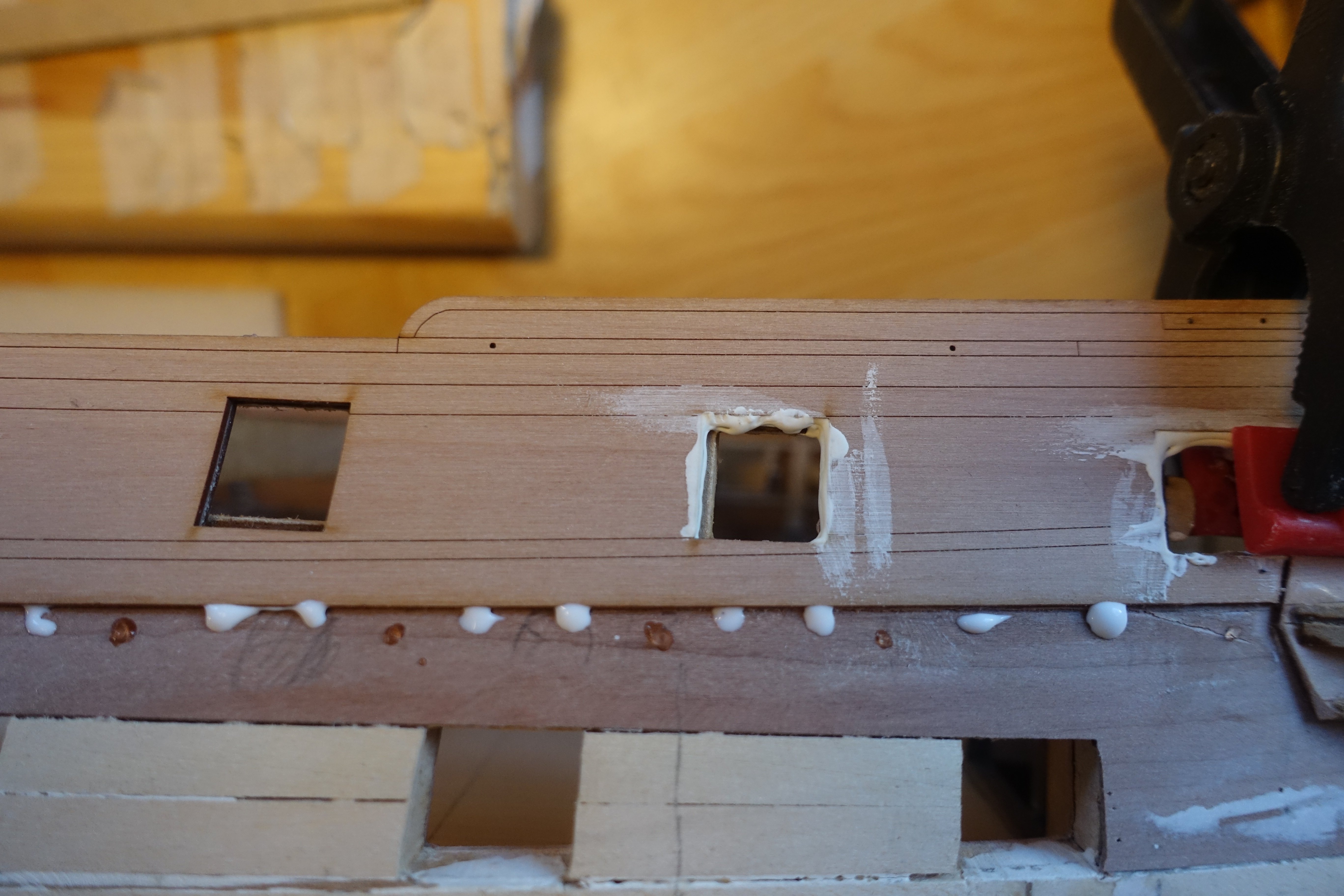
Planking the remaining bulwark / garboard strake on the port side When planking, I largely followed the building instructions. First, a strip was glued under the pattern of the outer bulwark. For this and the other strips, I alternated between cyano gel and PVA, using PVA mainly to create contact with the previously glued strip or pattern. A second strip was glued underneath and the openings for the gun ports were cut out/sanded. For the guiding strip of the wale, the distances between the lower edge of the gun ports and the upper edge of the wale were first measured at the individual gun ports and a marking tape was drawn along the points. Glue was applied accordingly and the strip was glued in place. Likewise, three strips were glued for the garboard strake. To plank the remaining bulwark, four planks were needed at the widest point. Accordingly, the strips were tapered at the stern and bow and then glued. The strips were attached in such a way that the space between the gun ports was left for the last strip, which made the adjustment much easier. The gun ports were then sanded free. It took longer than I thought. Now it's the turn of the starboard side.


-
First and last shroud is mostly sufficient. Clark
-
Chris has since provided the boats in 3D print/cast form, but I still like the original version better. If you take the necessary care, it's also a lot of fun to make them. Plus, as Schooner also found, with time you get more skilled at it. Have fun with it too. Clark
- 22 replies
-
- 2
-

-
- 24 ft Launch
- Vanguard Models
- (and 1 more)
-
Maybe you can glue small pieces of wood strip on the corners and under the rail of the Quarter Gallery, to simulate a transition to the rail of the transom. I think removing everything again will end in disaster. Clark
-
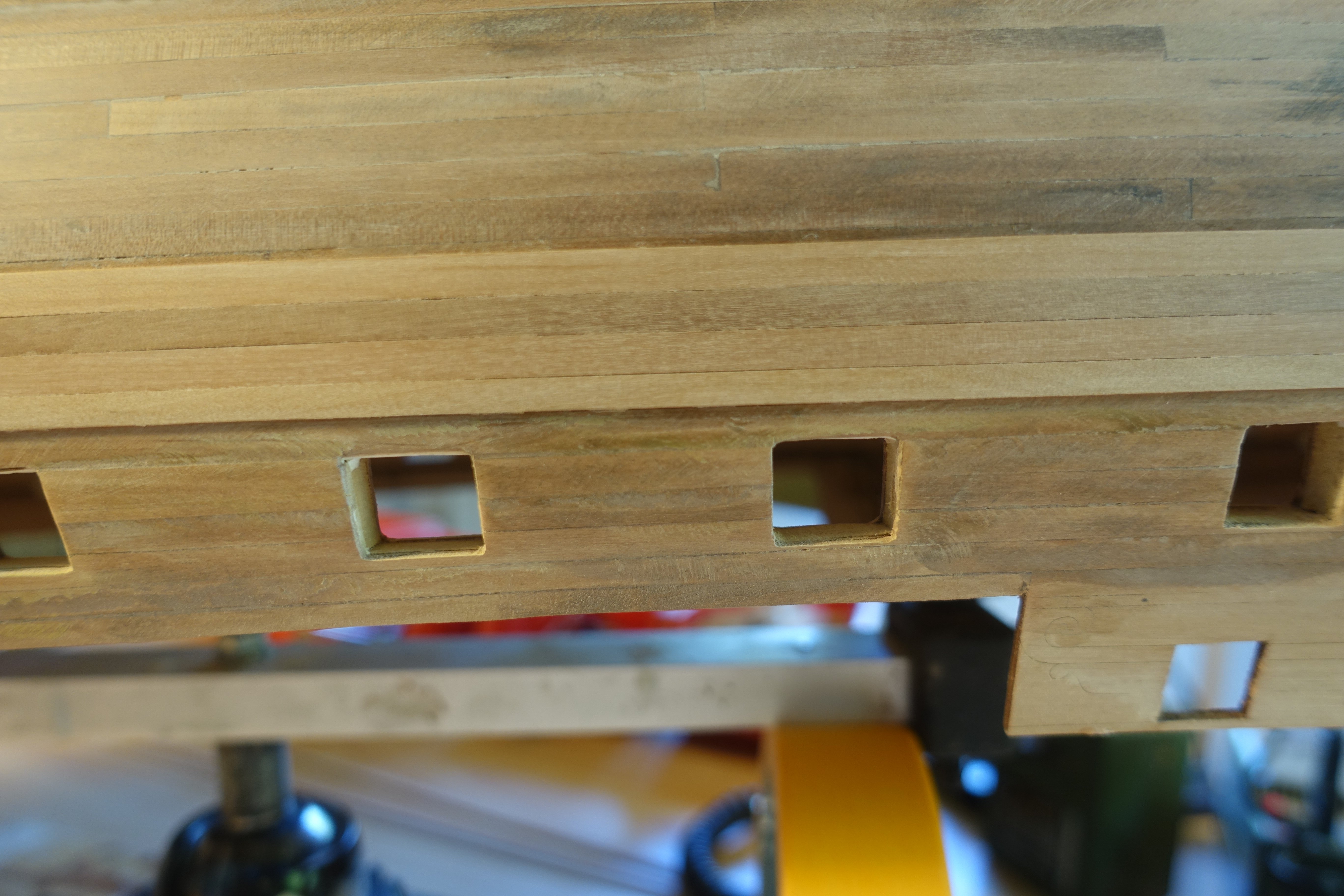
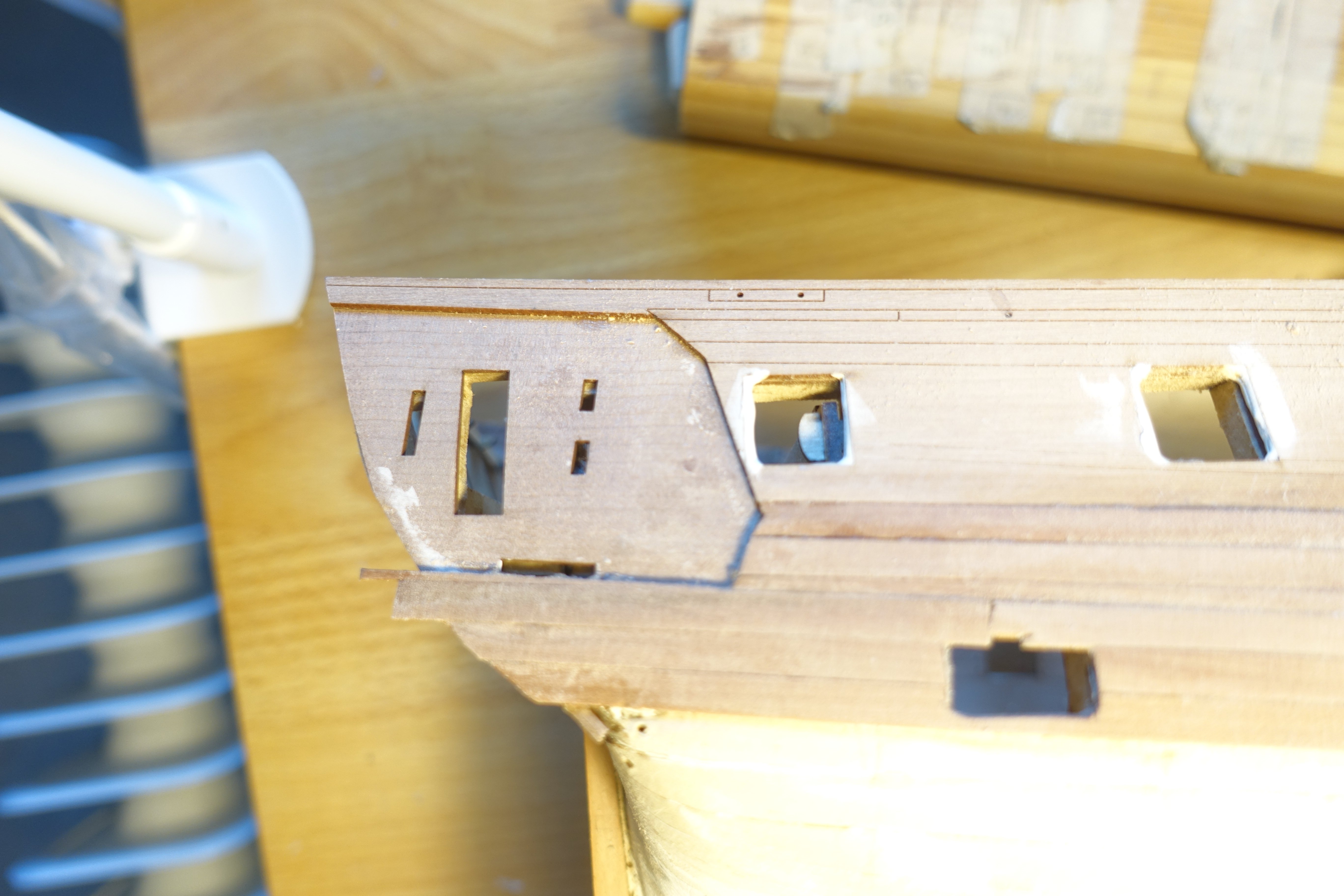
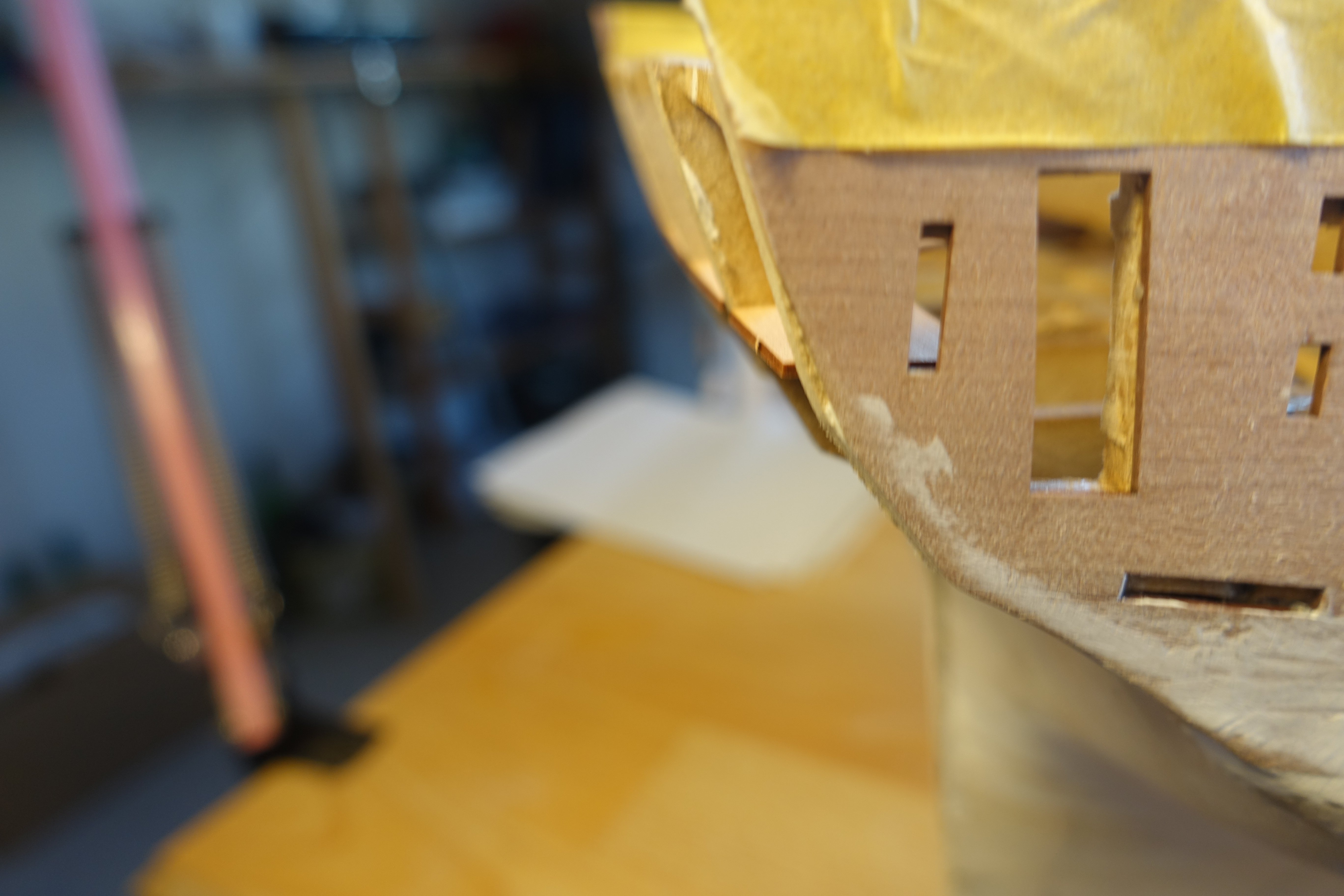
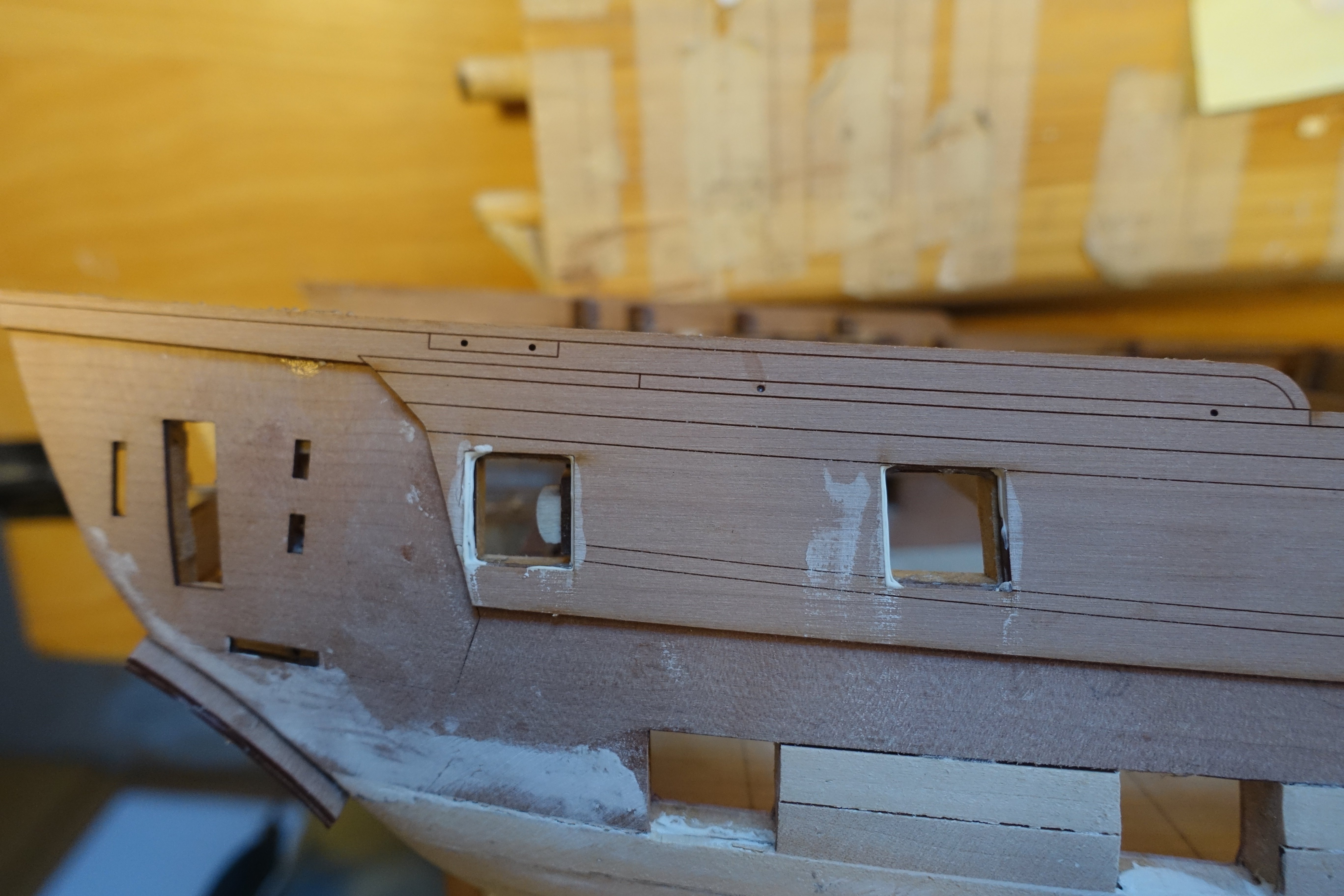
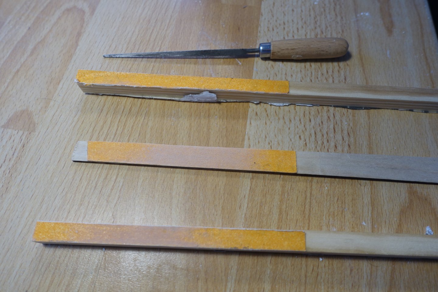
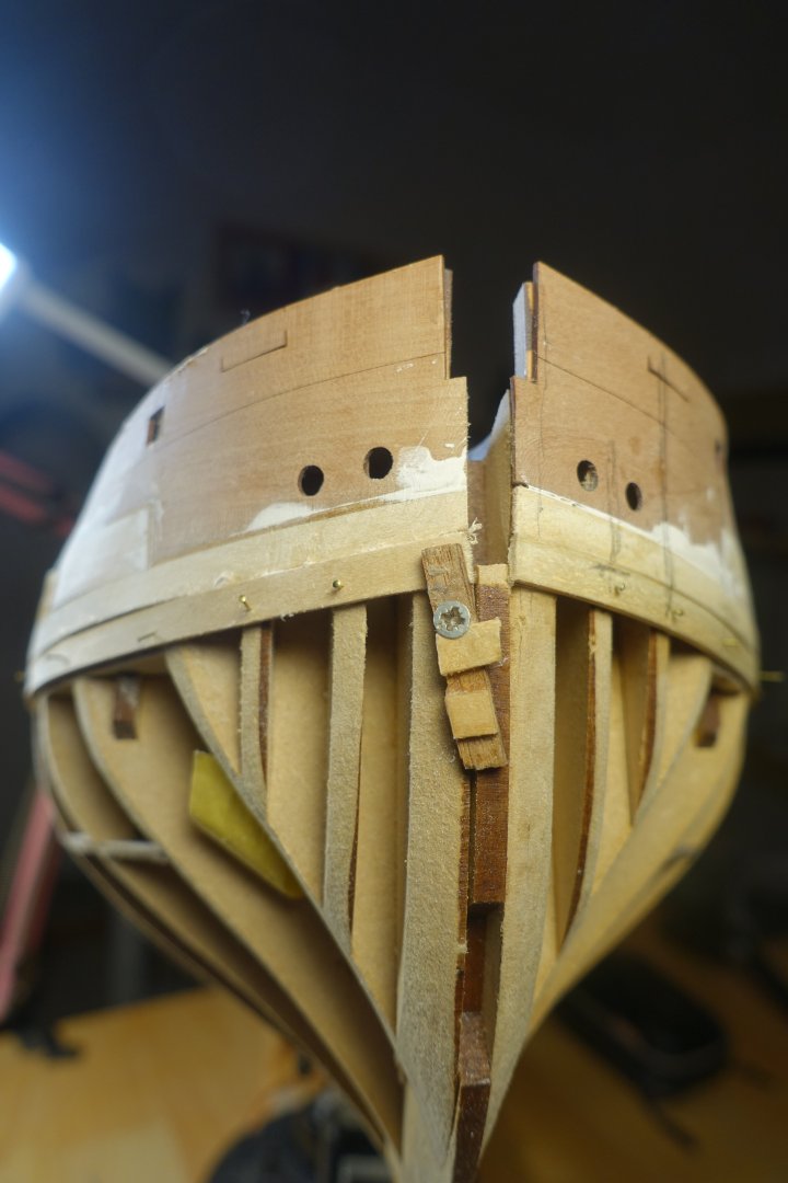
Preparing the second planking First, the gun ports were sanded flat. In the photo, you can see the sanding sticks and the file I used for it The rear side of the poop deck was adjusted. However, no sanding work was necessary on the deck. However, the rear supports protruded a little. The protrusions were sanded flat. The protrusions were sanded flat. The supports for the captain's cabin bench had to be lightly sanded. The bench protruded slightly and was then adjusted. The transom and upper counter were adjusted. The edge was lightly bevelled so that the edge of the counter would match the transom. The lower counter was watered and bent. The upper edge of the lower counter did not quite fit the upper counter. The counter was lightly sanded in the centre to make it fit. The lower counter was dry fitted, the lower line marked and the first planking removed accordingly. The lower counter was glued in. The cores of the stem post, keel and rudder post were glued in. The casings of the stem post, keel and rudder post were applied. These also form a rabbet for the second planking. The outer bulwarks in the stern and bow areas were glued on. However, the cut-outs of the outer bulwark for the last two gun ports were about 0.3 mm larger than the cut-outs in the underlying bulwarks. The gaps were filled. With the other gun ports, everything fit exactly. It may be because I watered the inner bulwark and not the outer one. However, I let it dry for more than 24 hours.


-
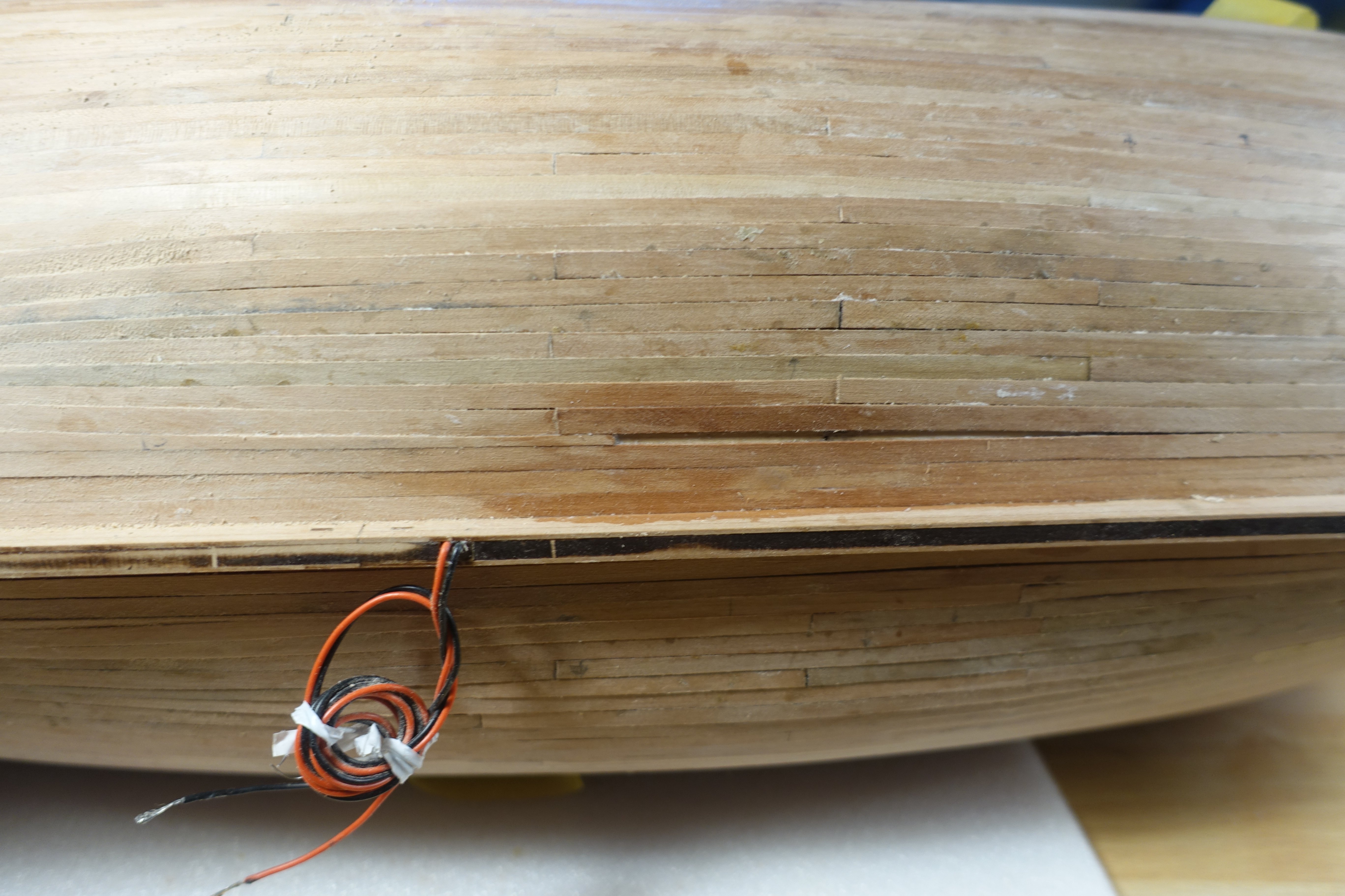
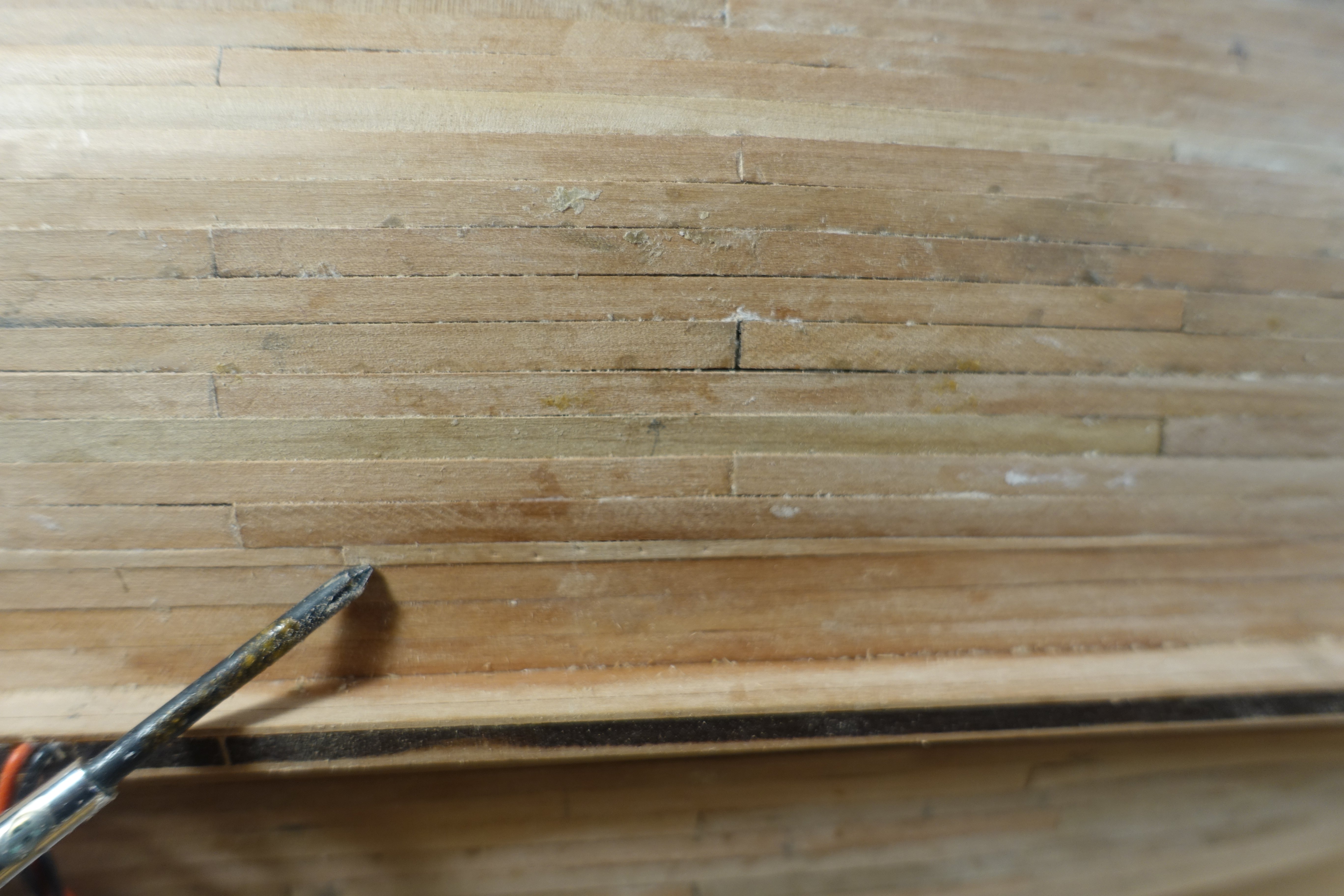
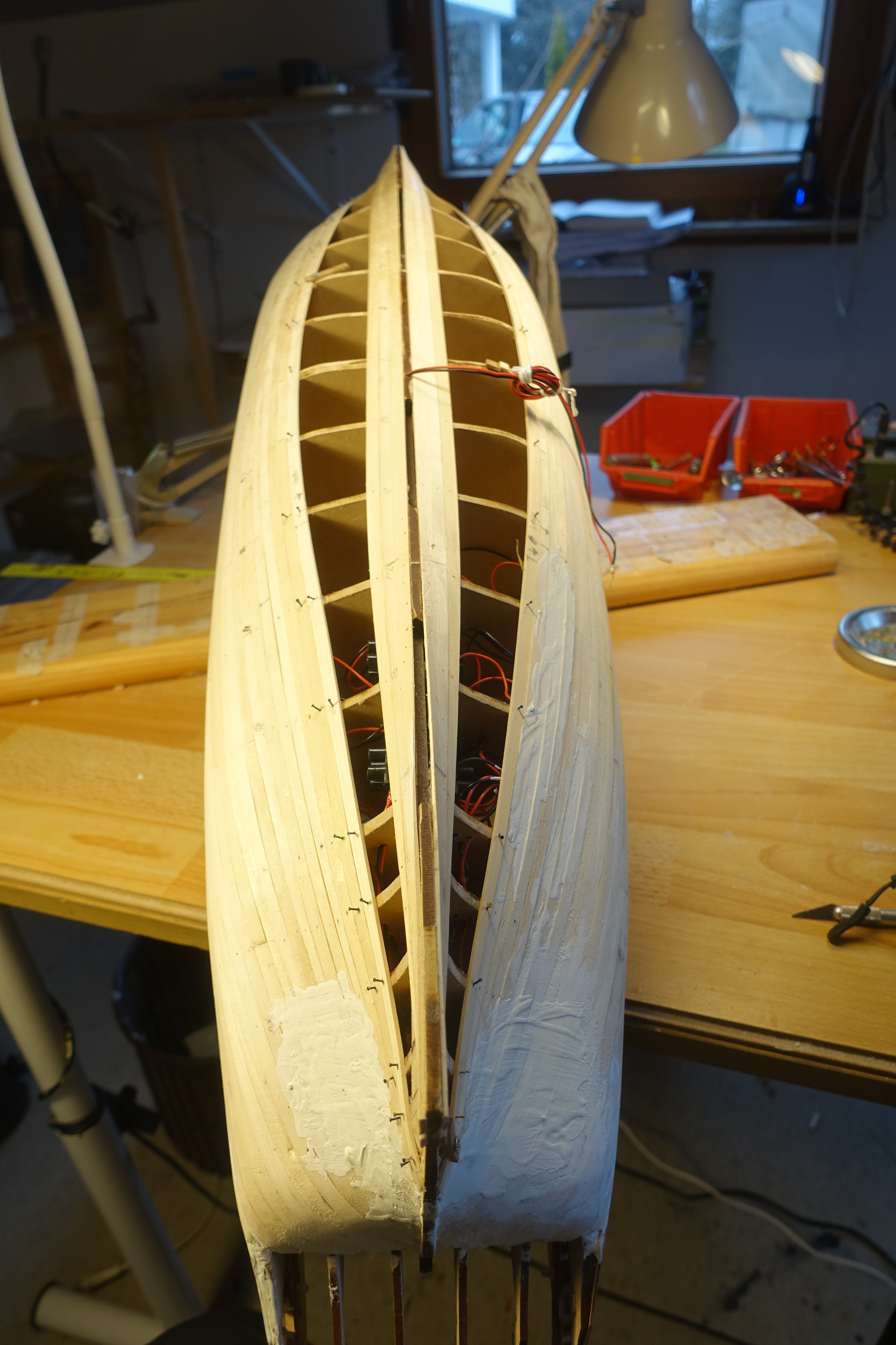
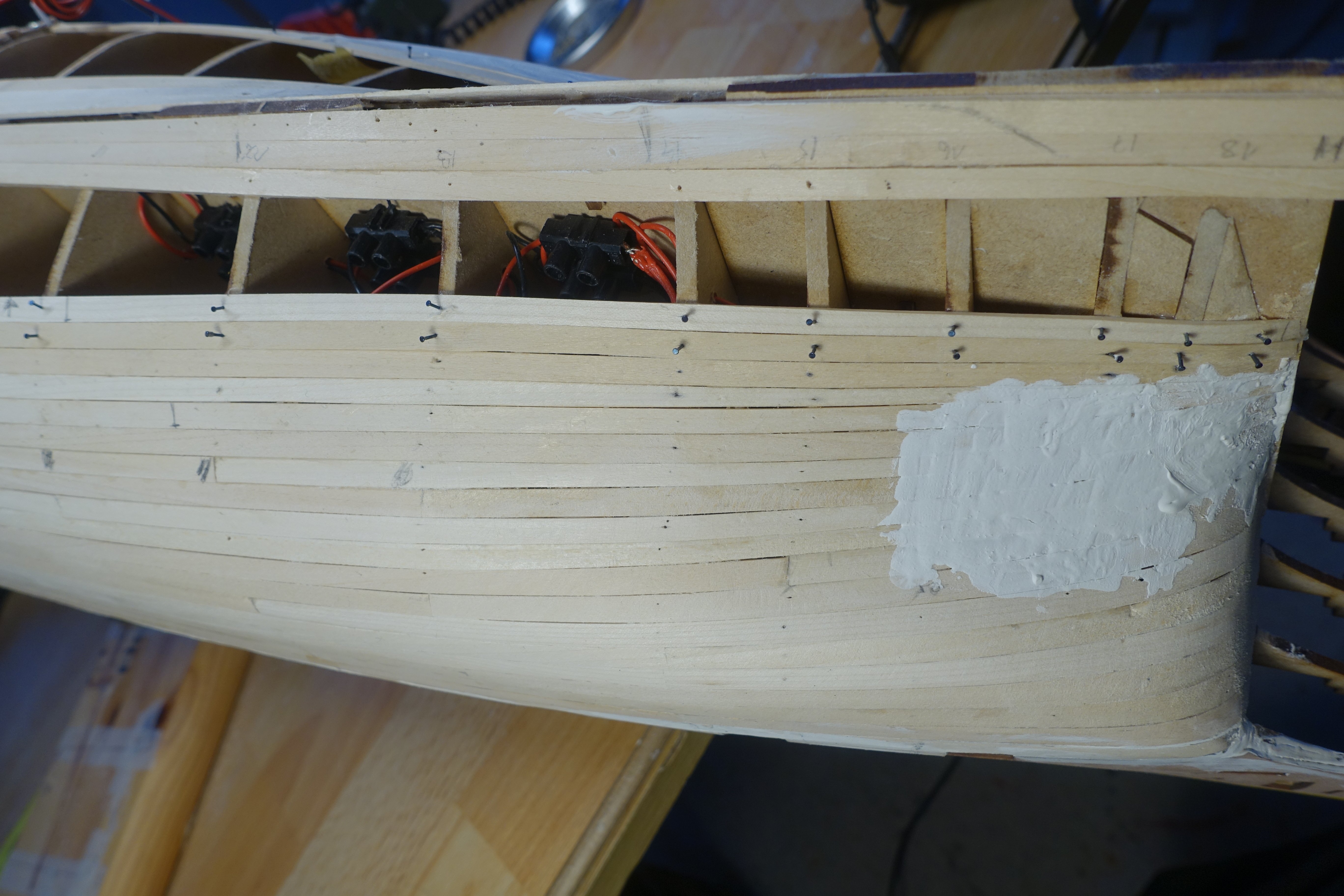
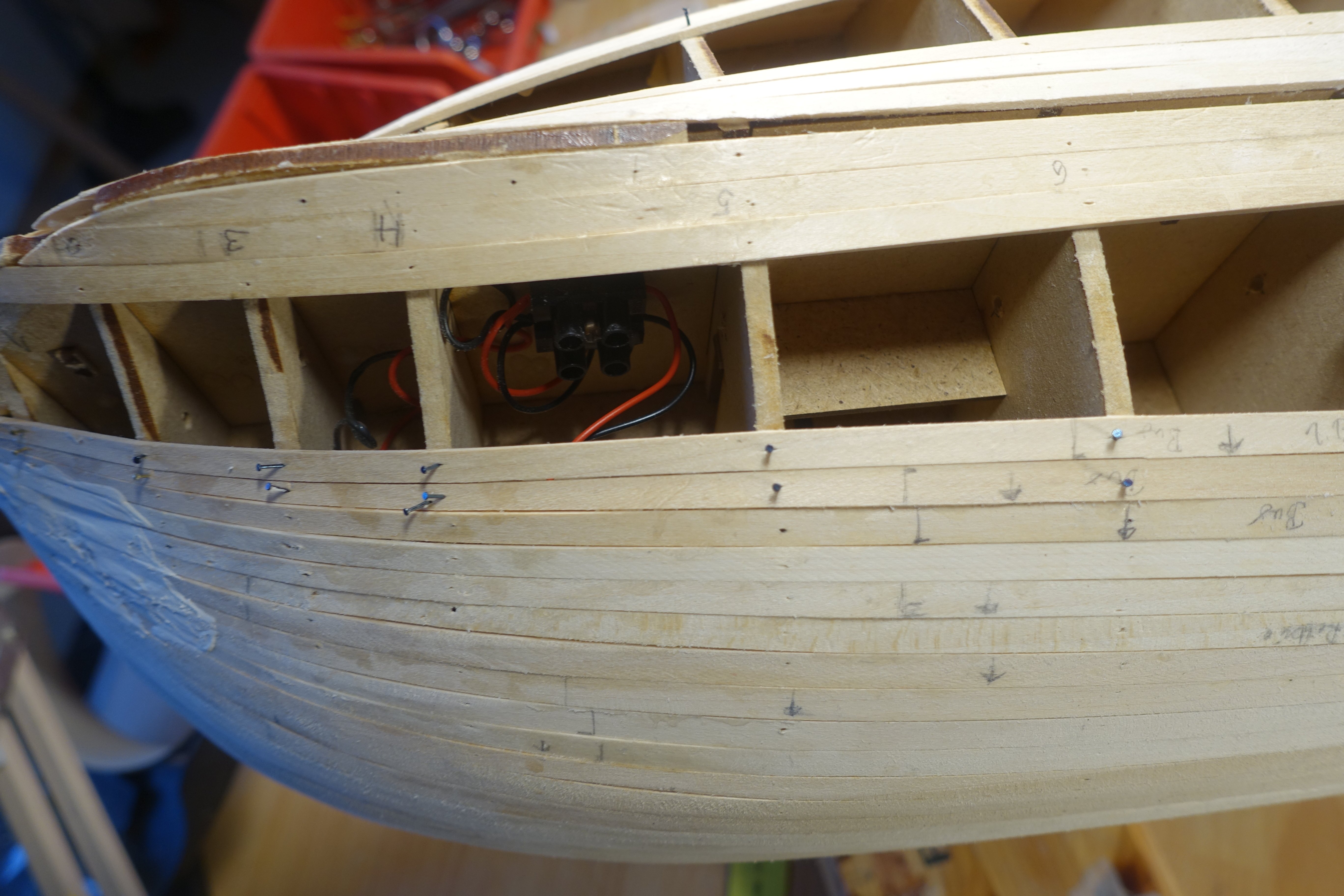
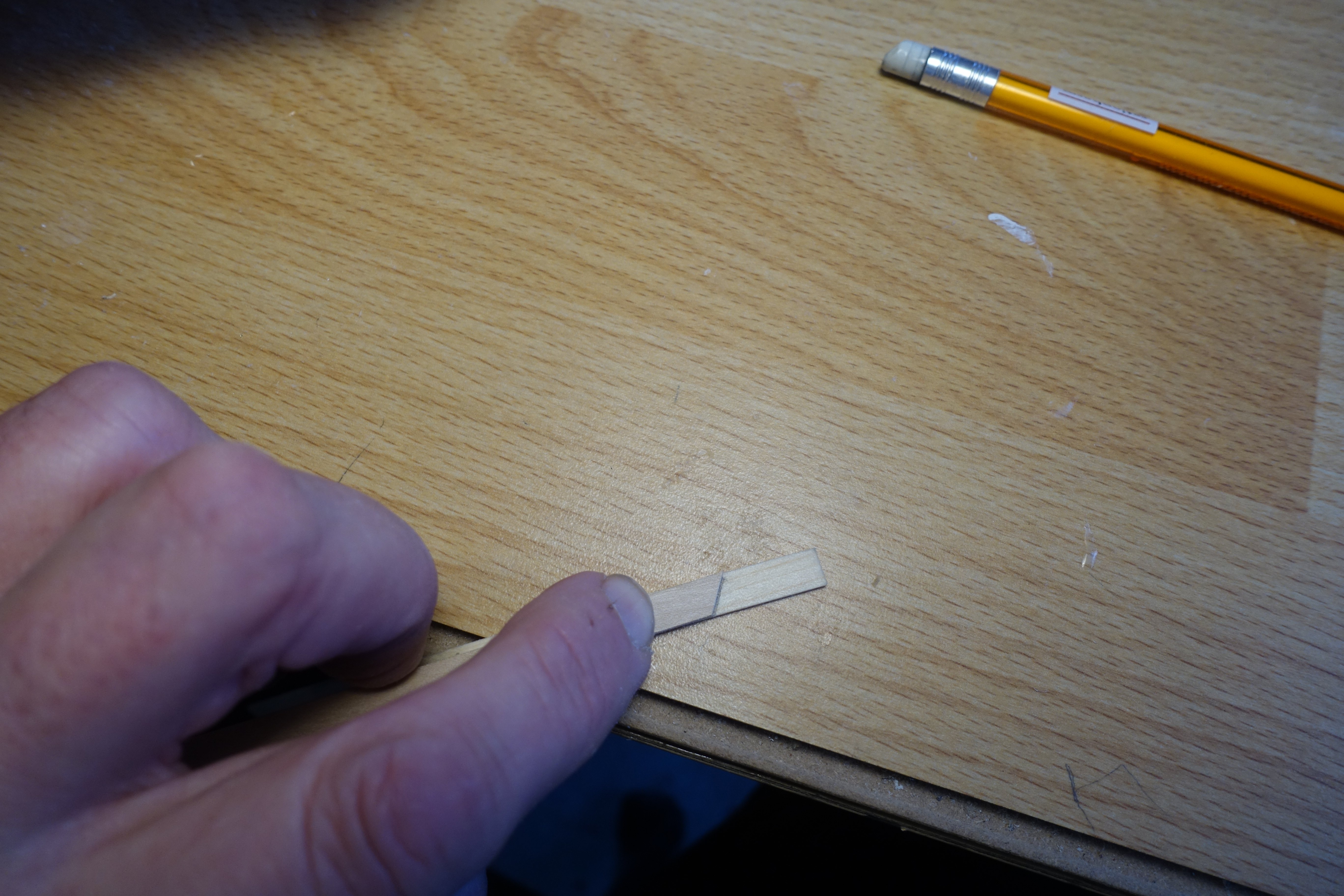
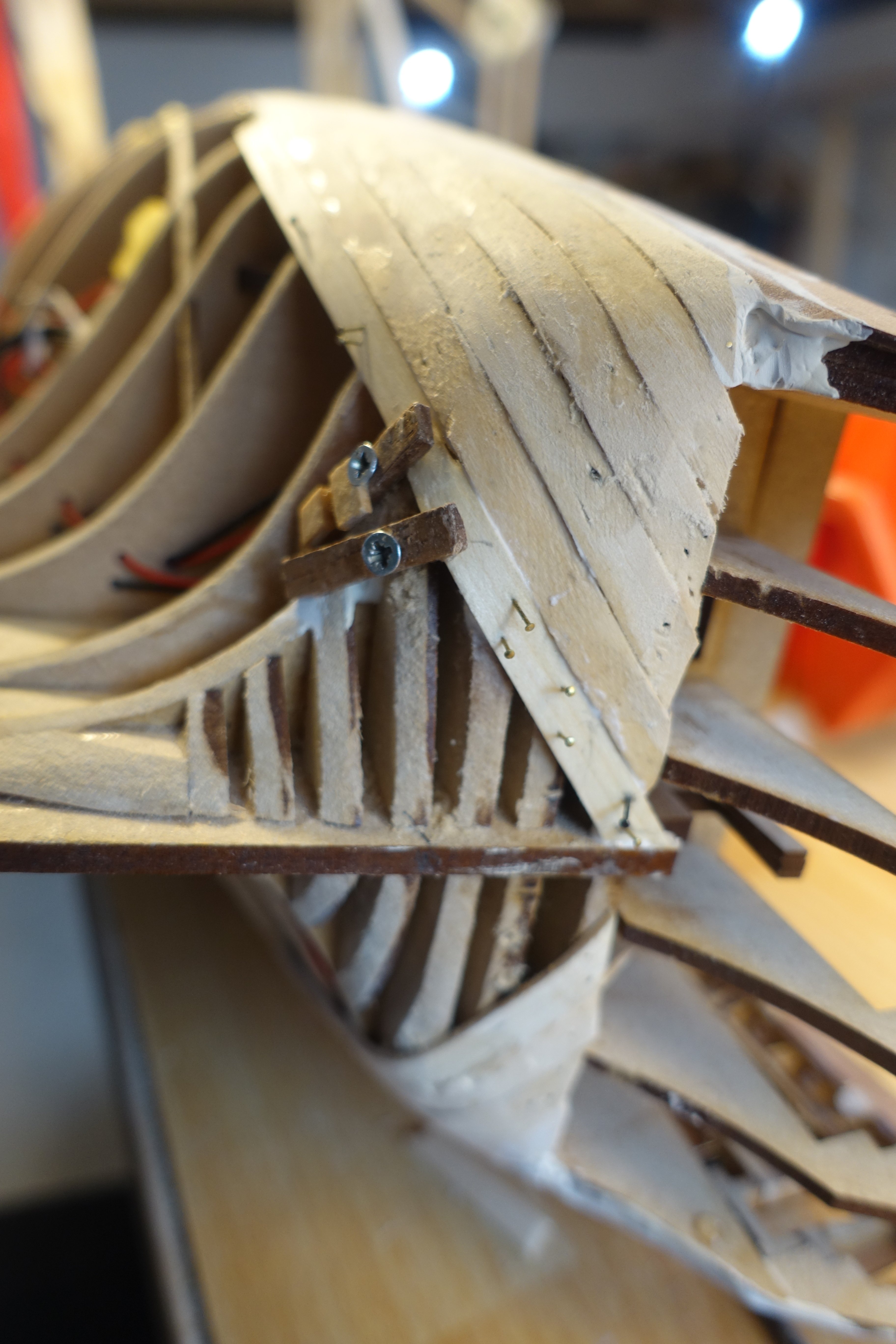
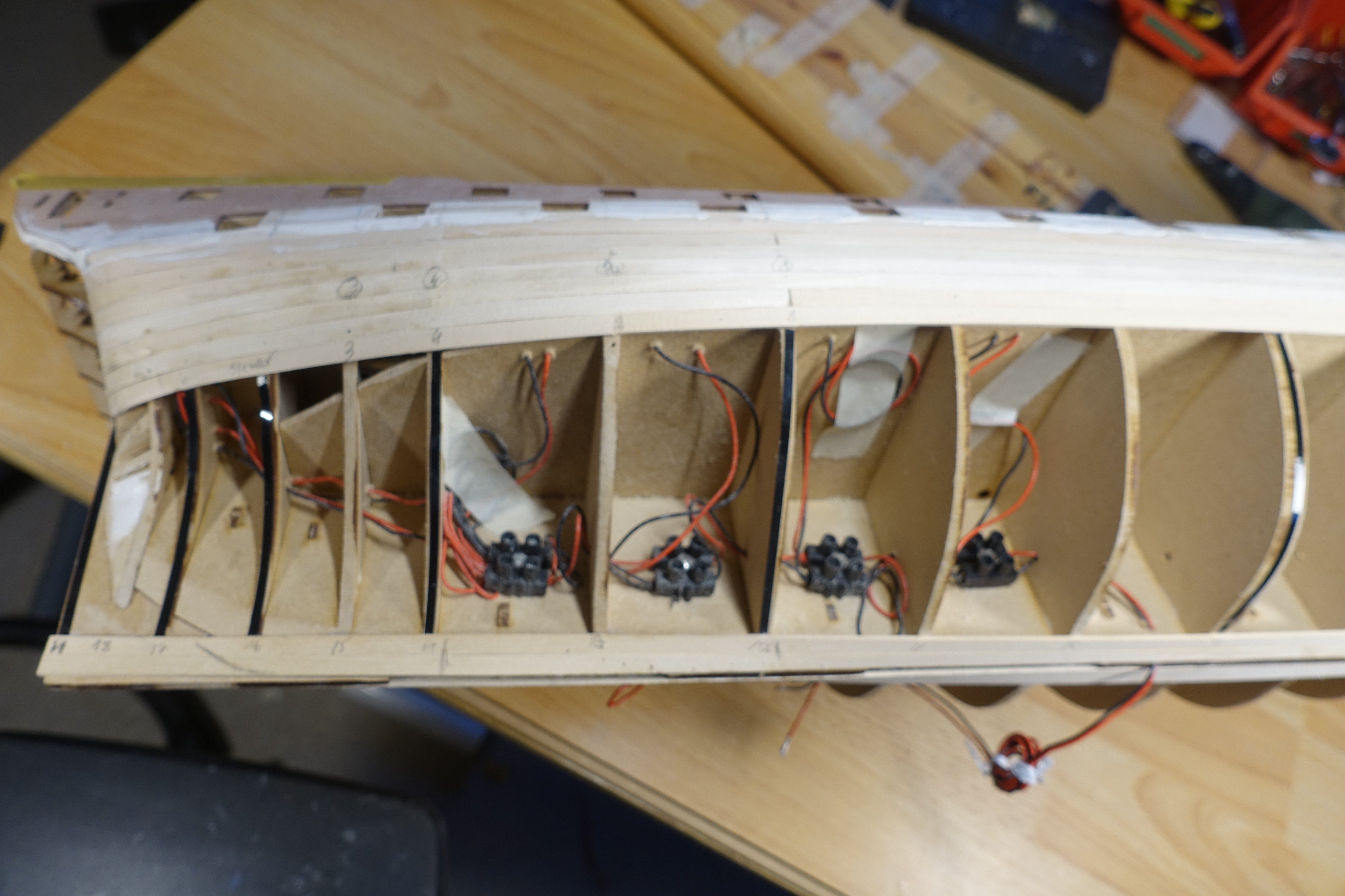
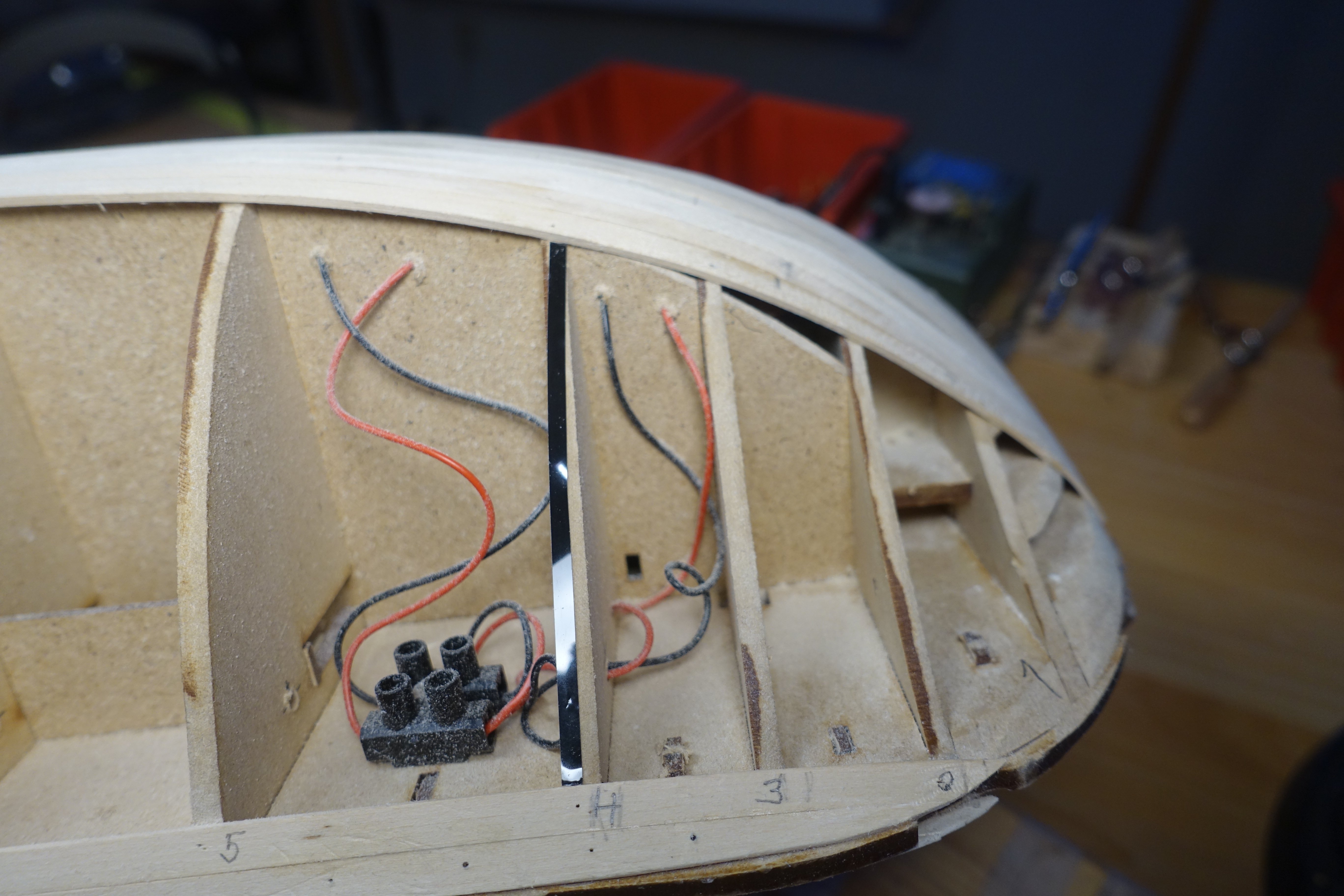
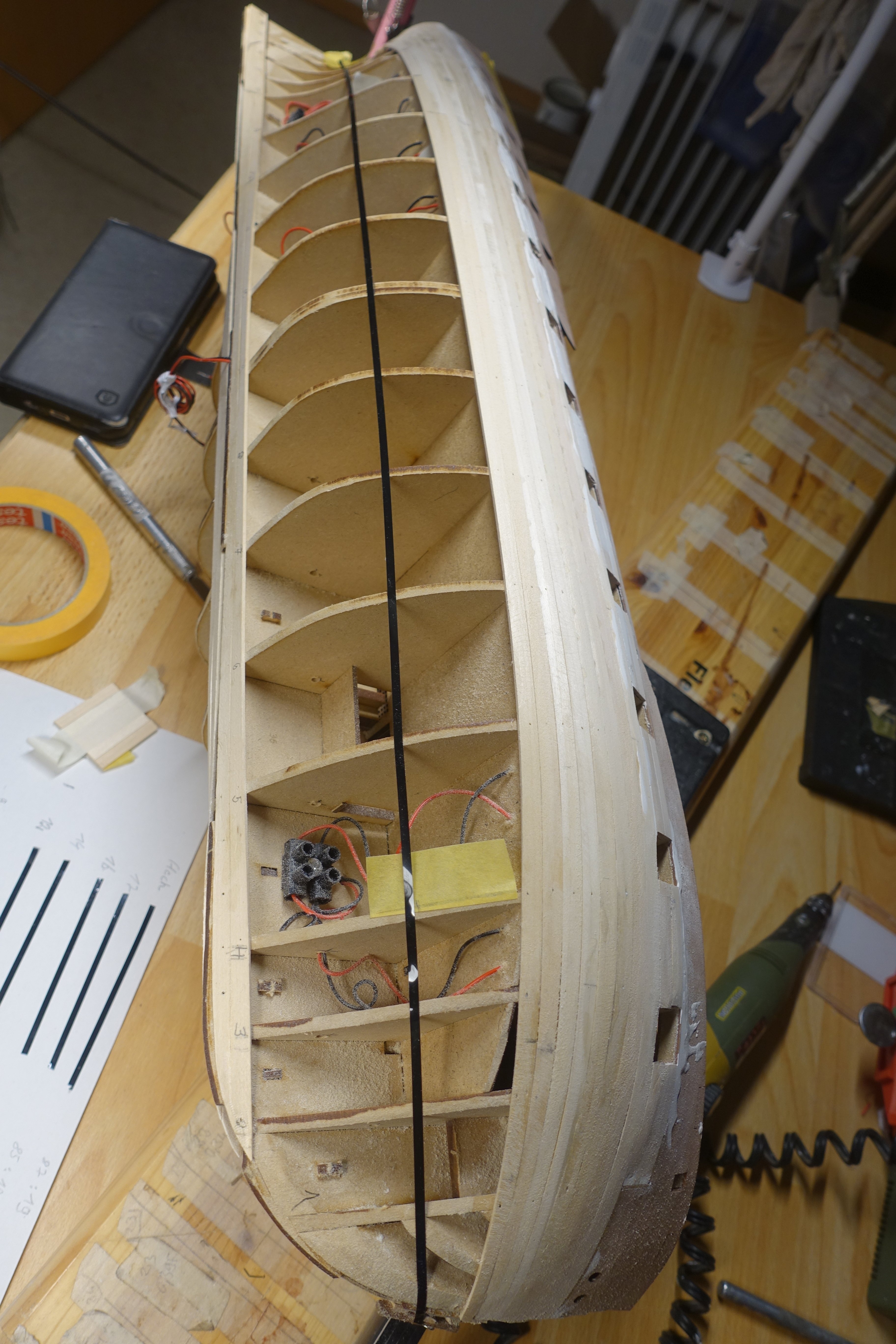
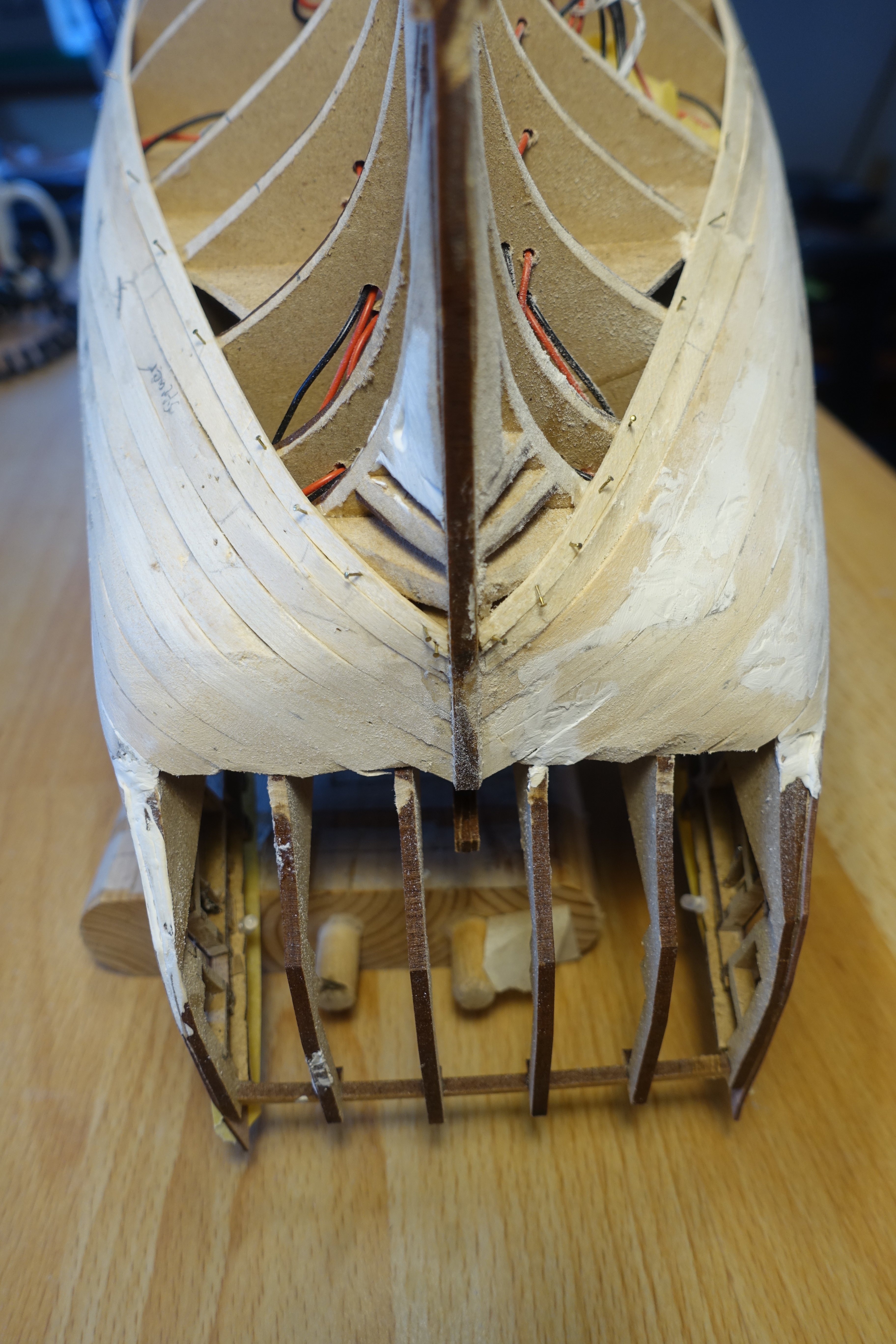
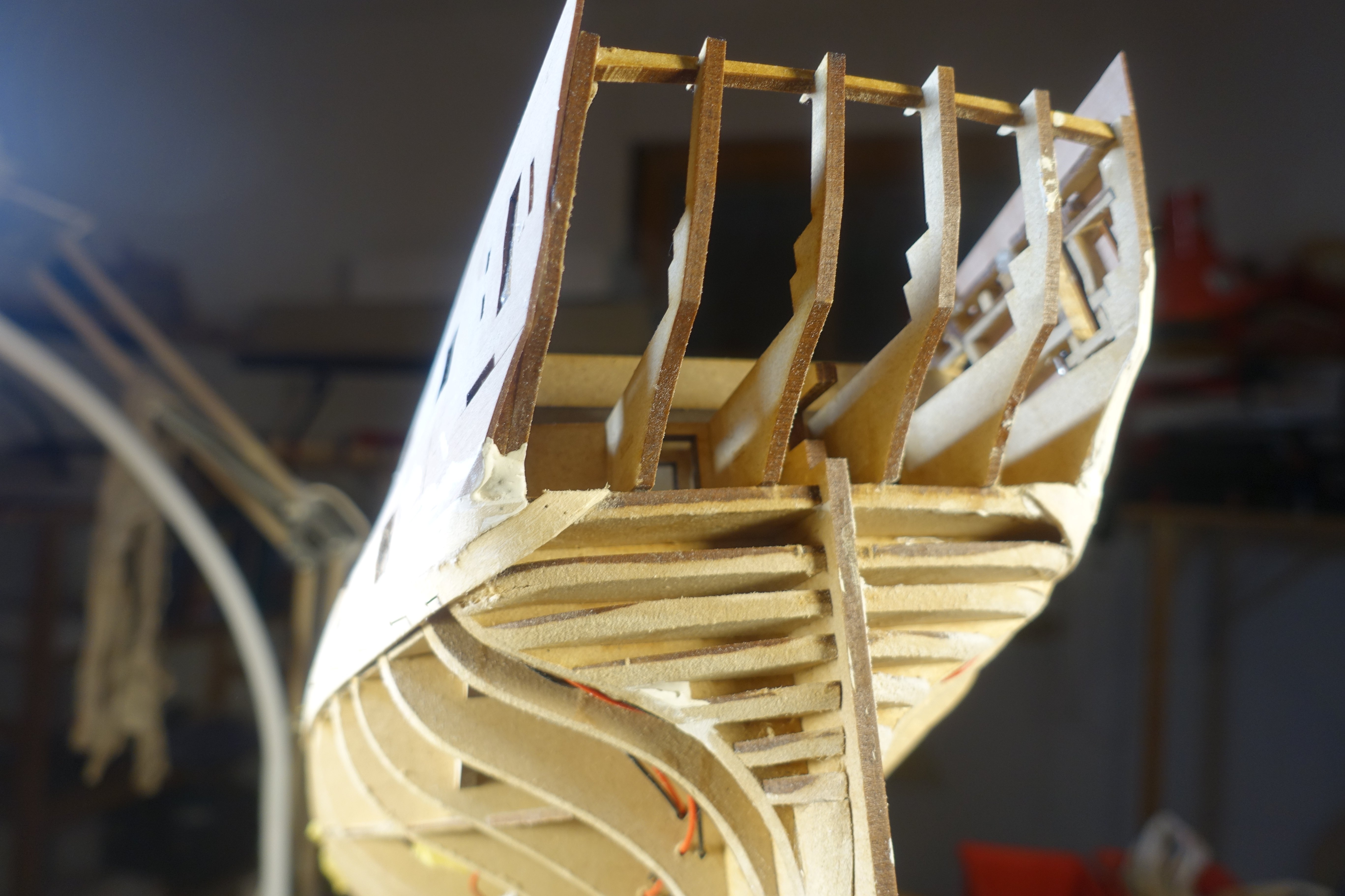
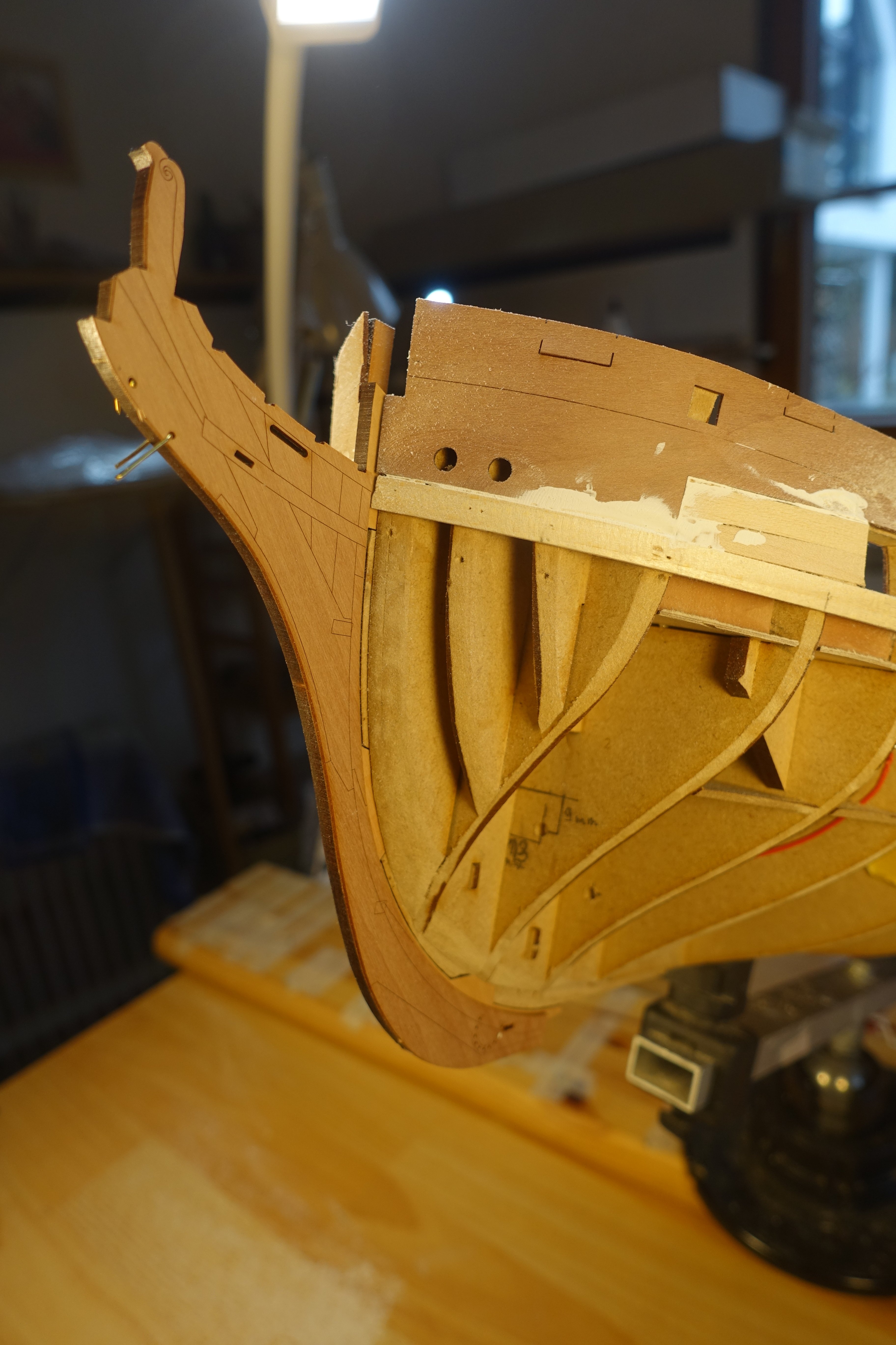
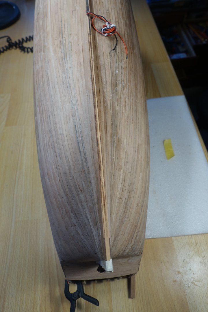
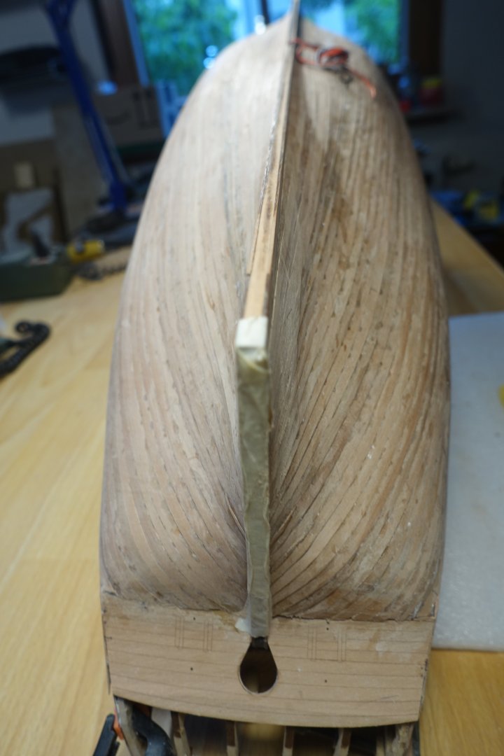
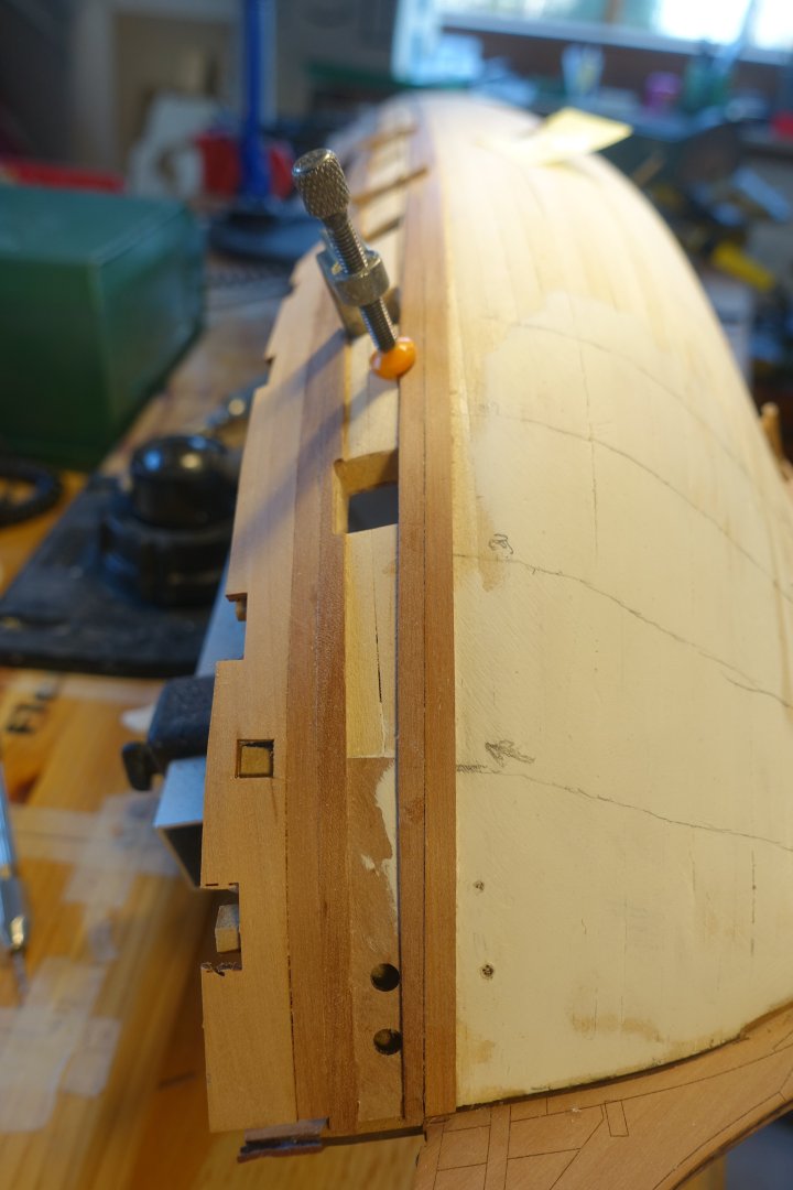
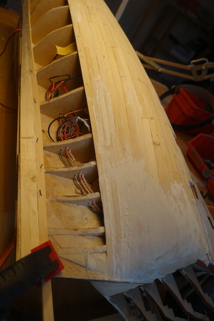
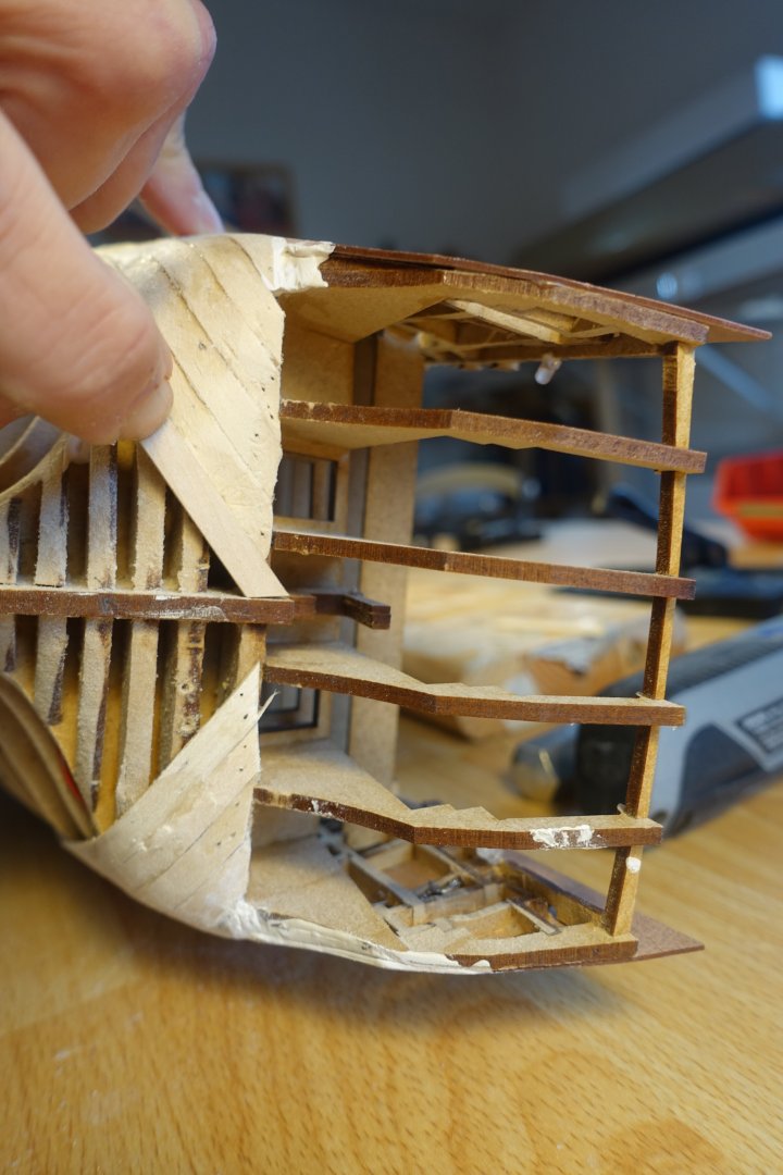
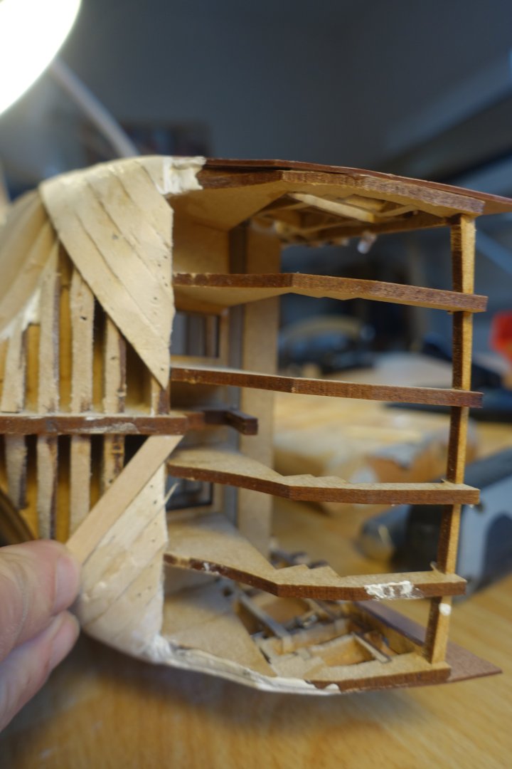
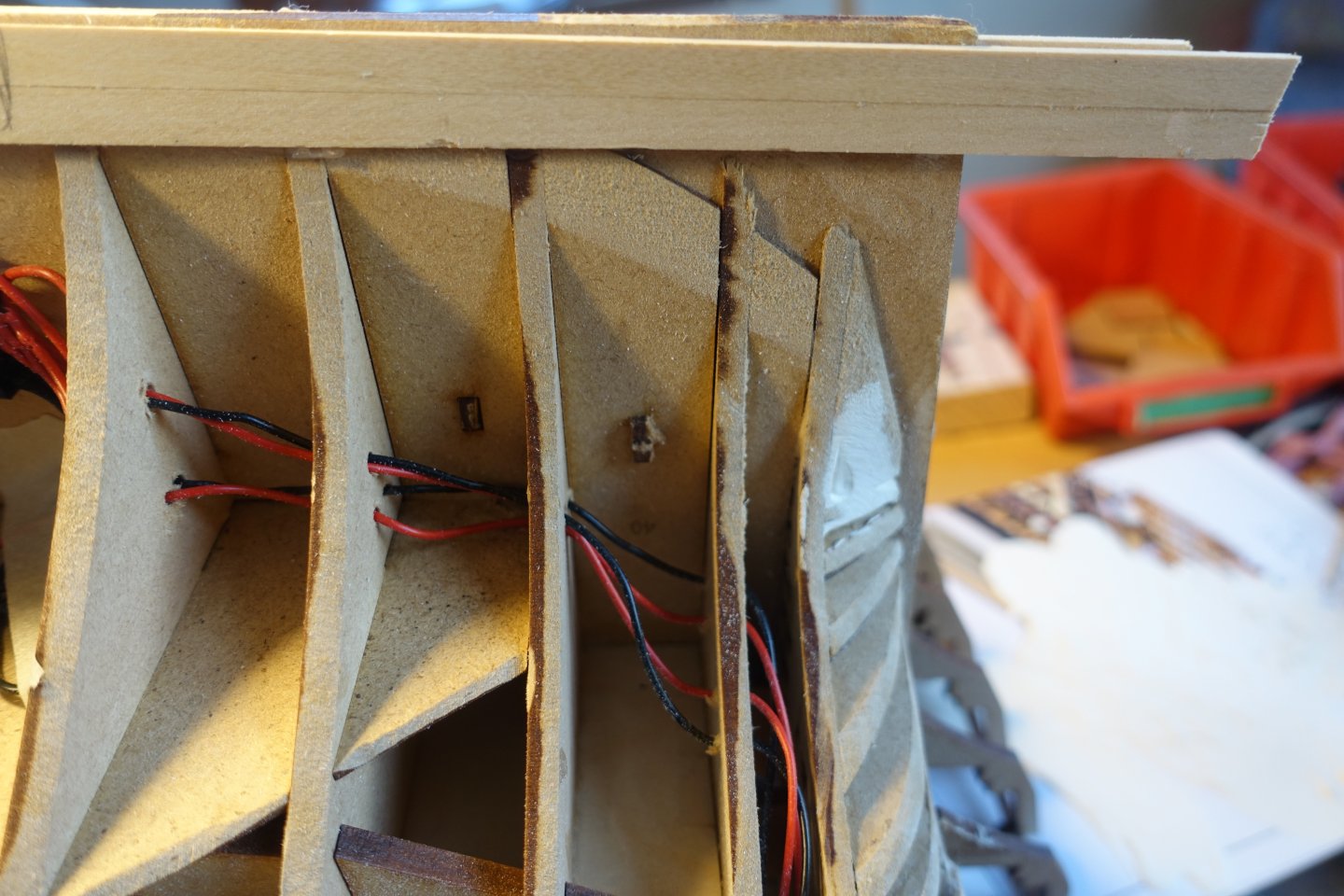
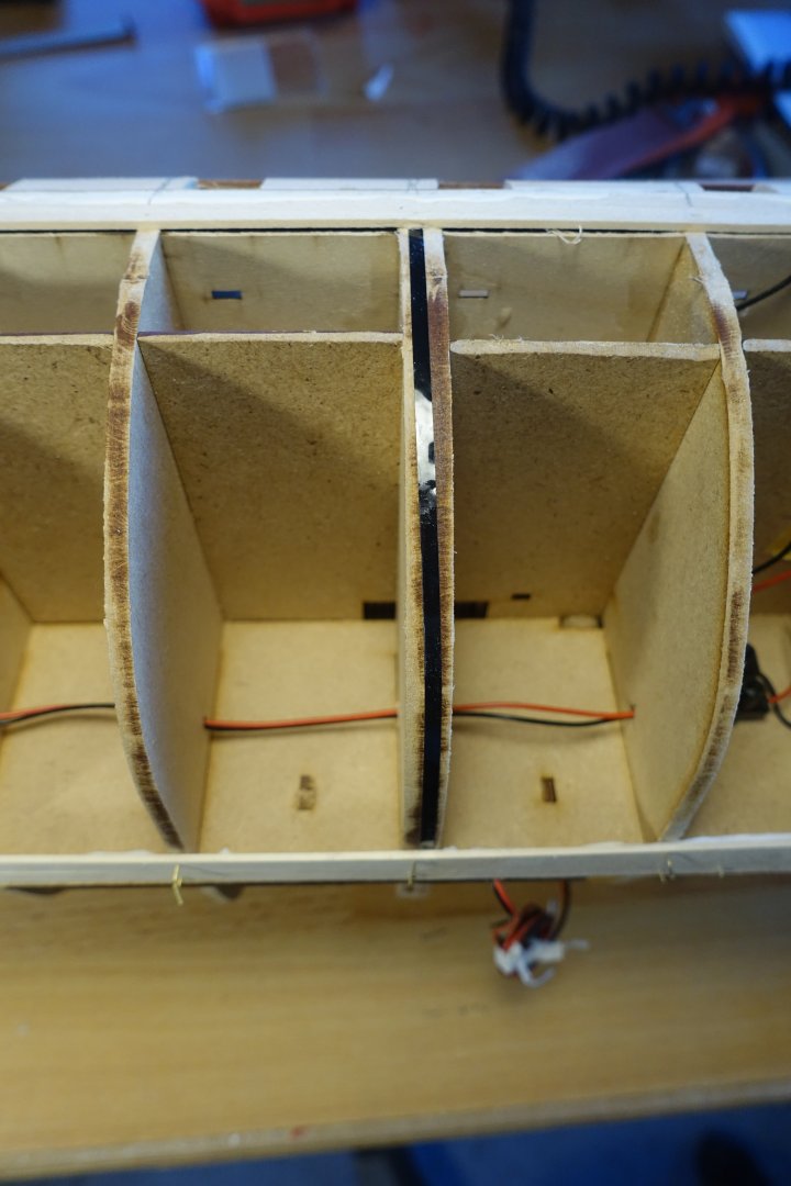
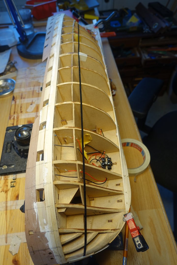
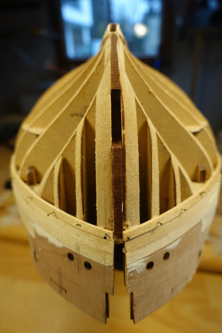
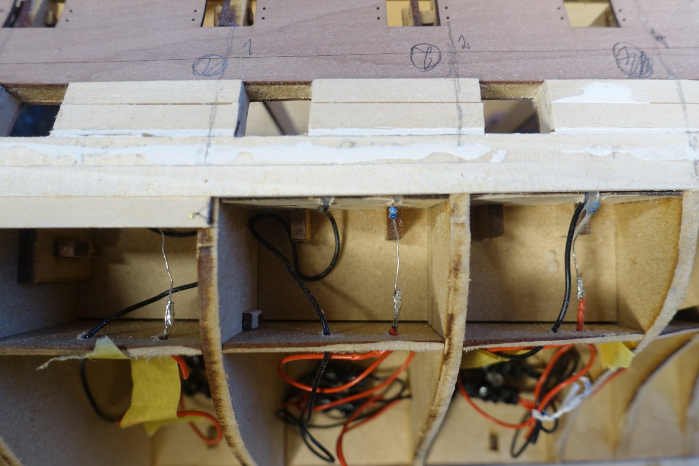
Sanding first planking First of all, I used the Dremel to smooth out the transitions and protrusions between the strips. All further sanding was then done by hand with 60 and 120 grit sandpaper. Then, with the help of the dry-fitted casings of the stem, keel and rudder post, I checked whether there was enough space to be able to carry out the second planking with the one-millimetre strips later. The casings form a rabbet against which the strips of the second planking will later rest. As can be seen in the picture, the strip does not make close contact in all areas at the bow. This is especially the case where the inner core of the stem post is fitted. Nevertheless, I will not make any corrections yet because I want to see how the planking will turn out in the end. In the area of the keel, the template for the garboard strake fits perfectly. A small slot had to be filed in the inner keel for the LED cables to exit There was not a well formed rabbet in the area of the rudder post. This is mainly becauseI filled some areas with filler. Excess material was sanded. I hope everything is prepared for the second planking.


-
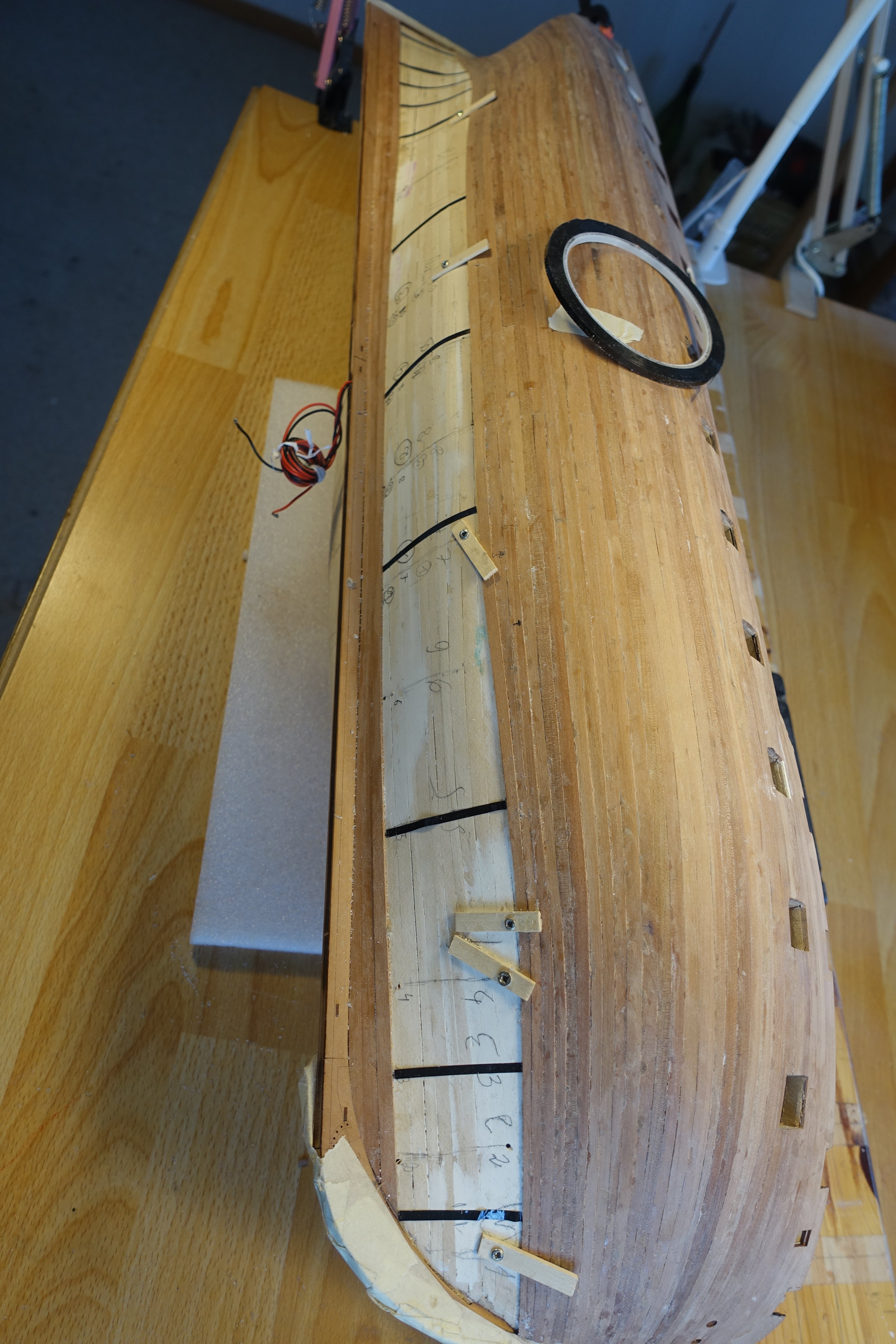
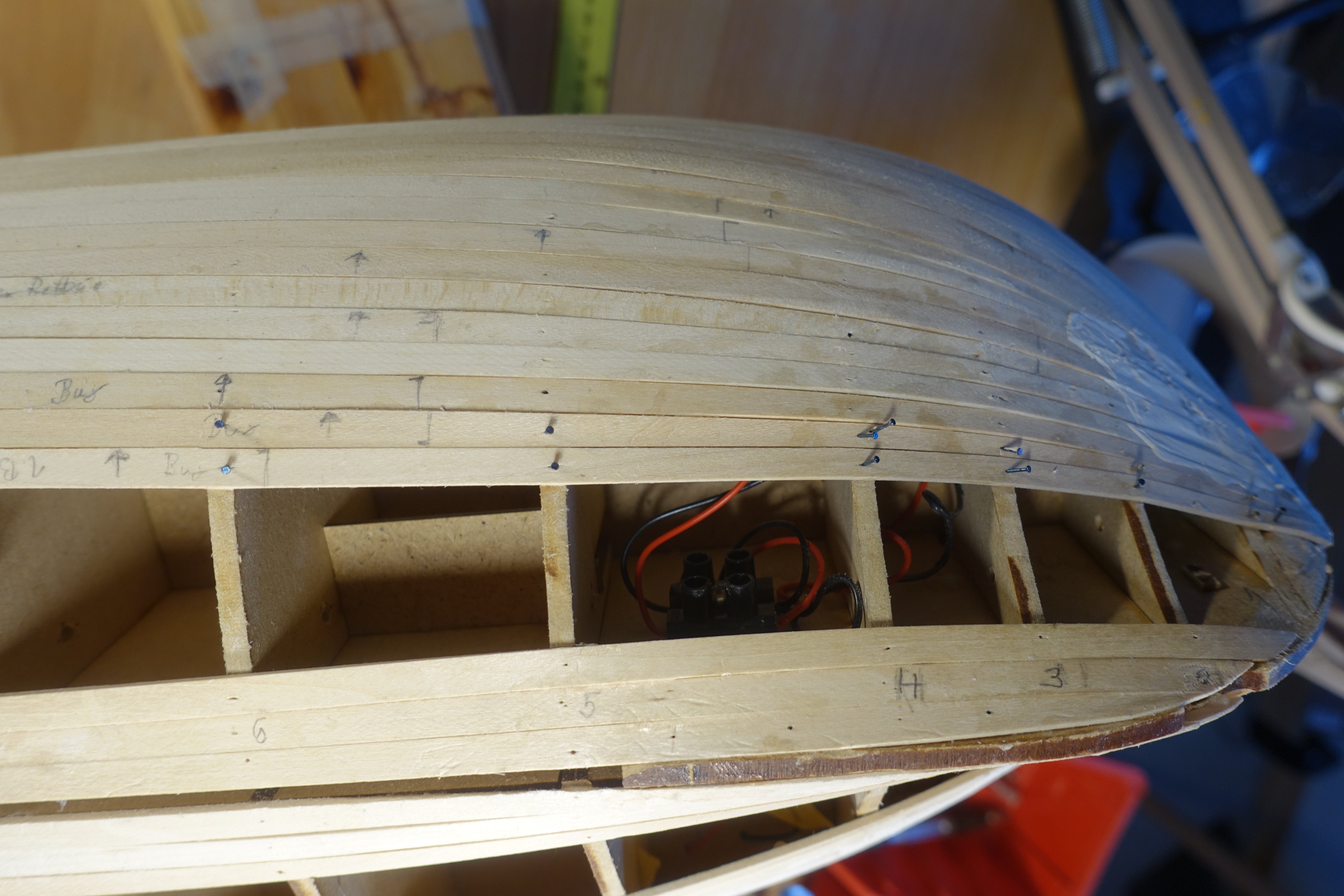
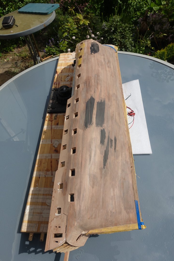
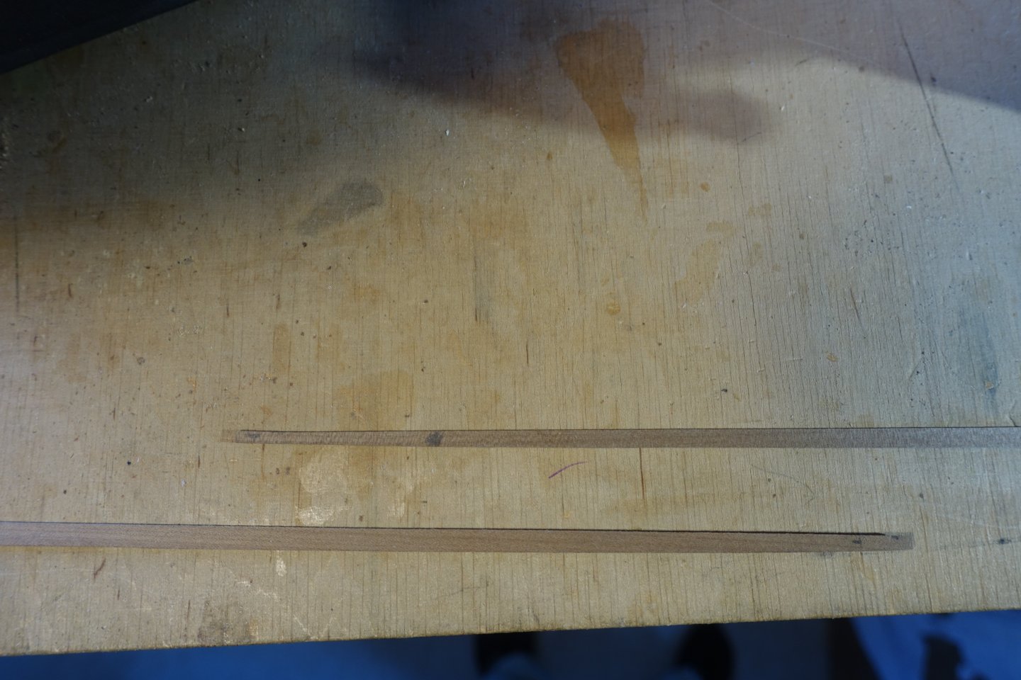
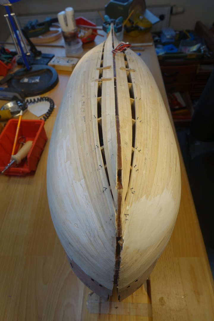
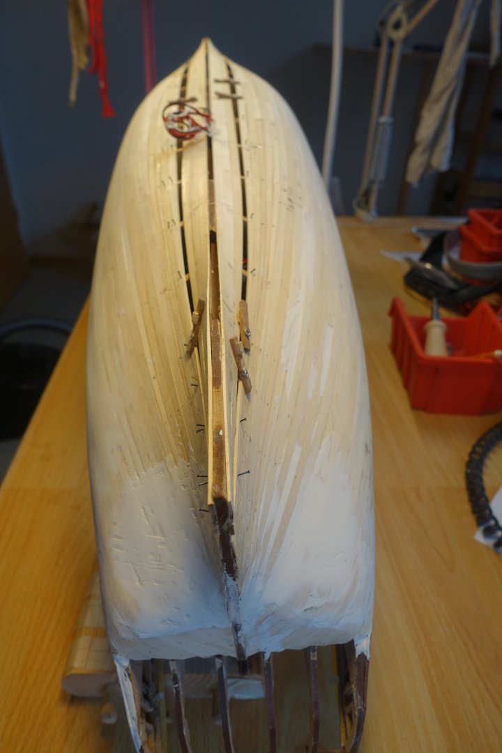
After 6 planks per side had been attached, the width of (this time) 5 planks was measured at frame 9 and the distances at the other frames measured with the help of the marking tape and Chuck's planking fan, An additional plank was fitted above the garboard strake, as I find it more comfortable to fit the last plank at this height. Further progress on planking There are only a few planks left now. I have already applied some filler in some places to close gaps. At frame 9 it becomes clear that a little more than 6 planks have to be fitted. Nevertheless, I have calculated with 6 planks. Towards the stern, the narrow point is at frames 13 and 14. I decided not to use stealers, but to taper the planks accordingly. Plank section starting at the stern (starting point (stern) left), fully tapered Plank section starting at the bow (right), fully tapered. In this way, 5 planks were laid until only one plank layer was missing. Here you can see the strong tapering of the planks in the area of frames 13/14. The last plank was divided into 3 sections. The plank starting at the bow reached to frame 8. It was fitted by eye, i.e. holding it, roughly marking and cutting it, and then filing it. Fitting the stern strip and centre strip Centre and stern strips attached. As you can see, I did the planking differently from the James instructions up to the area of the rudder post. I think it's easier to get a smooth transition this way when sanding. Now, sanding is next. As can be seen in the pictures, I have already partially started with it. But it is far from being finished. Given the size of the hull, it will probably take some time.


-
Thanks. Looks fine.
-
Patina sounds good. But by copper patina I mean a green colouring. Can you post a few pictures so that we can see this? Does the patina intensify over time? Which sealer do you use? Clark
- 20 replies
-
- 1
-
-
- Indefatigable
- copper plates
- (and 1 more)
-
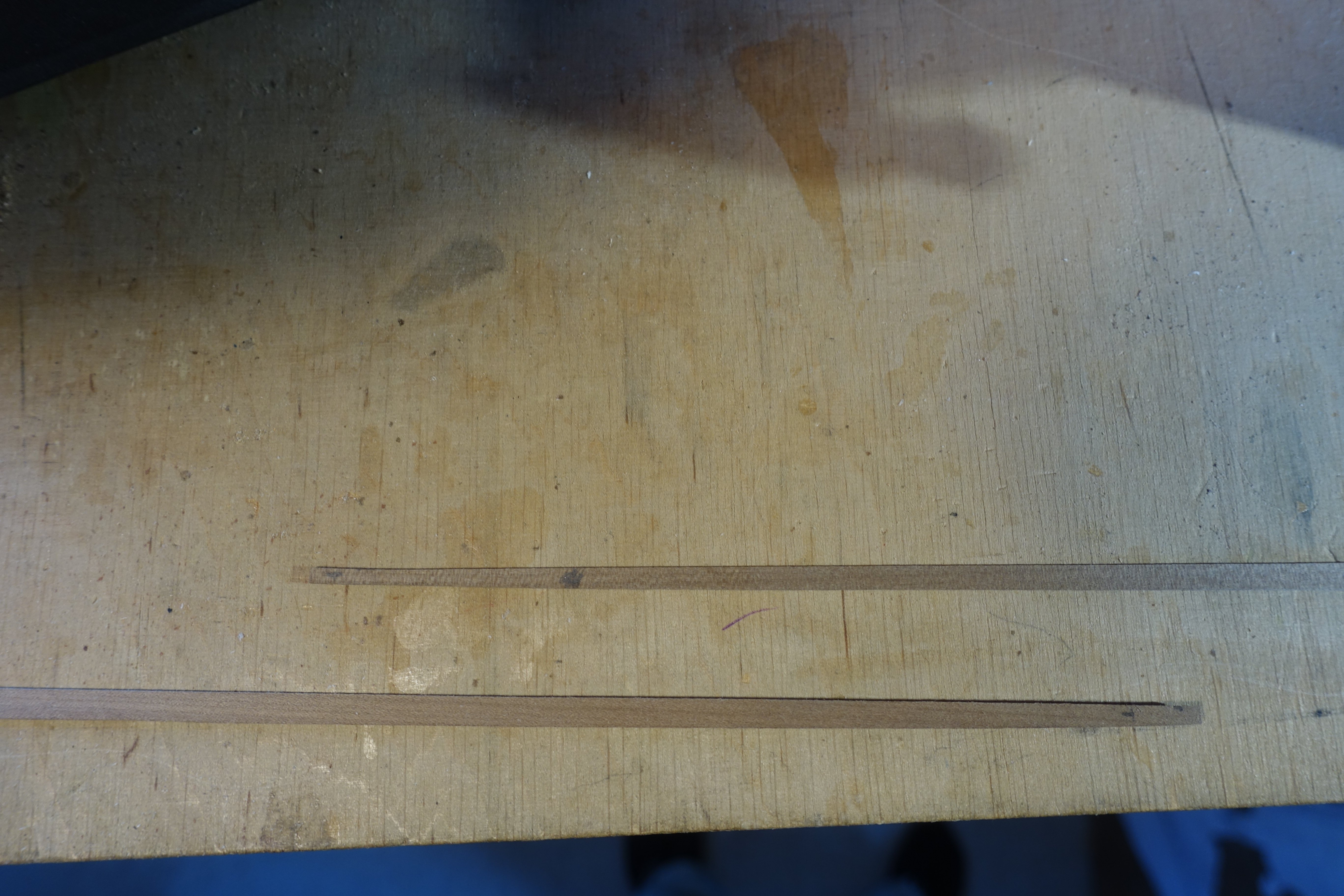
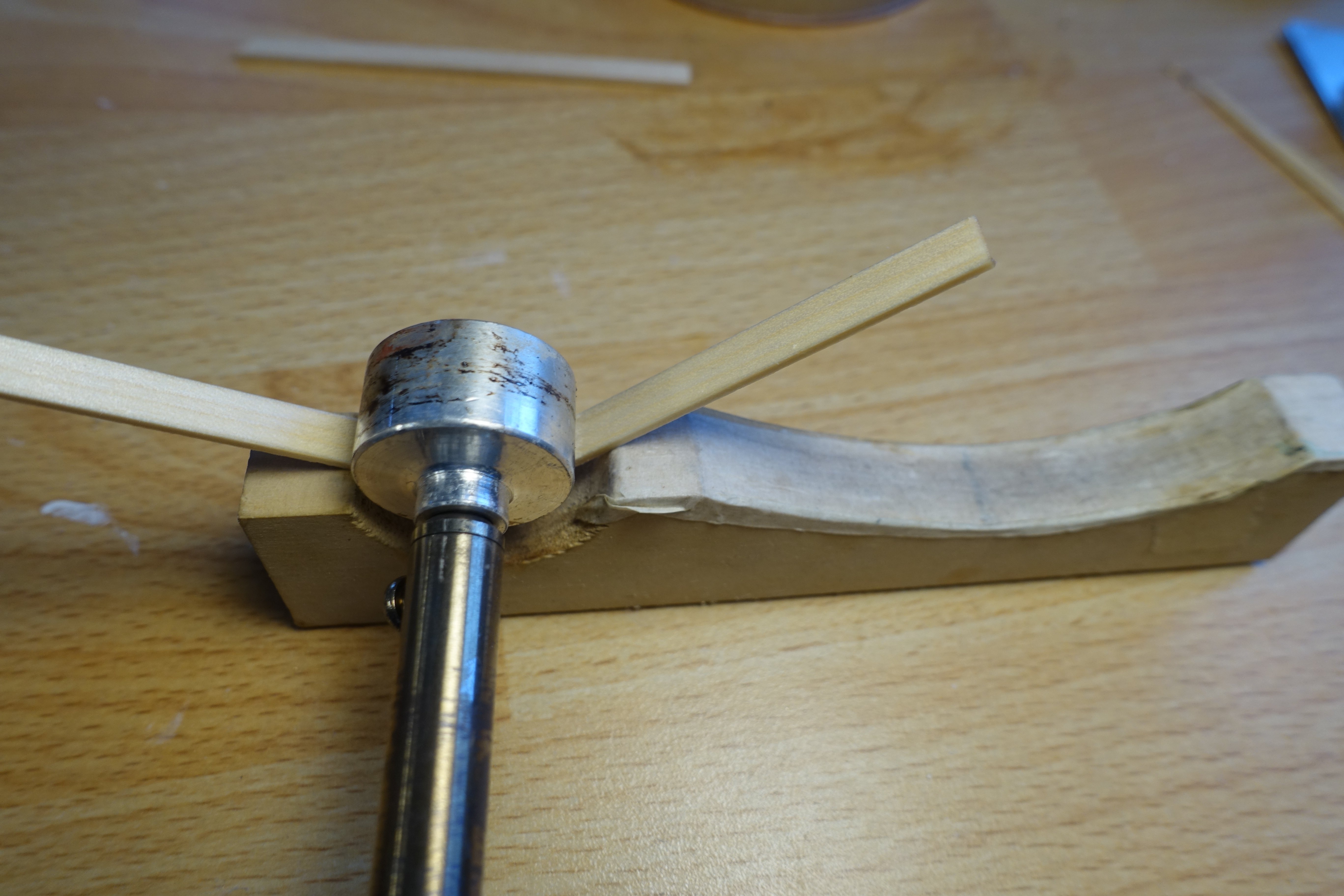
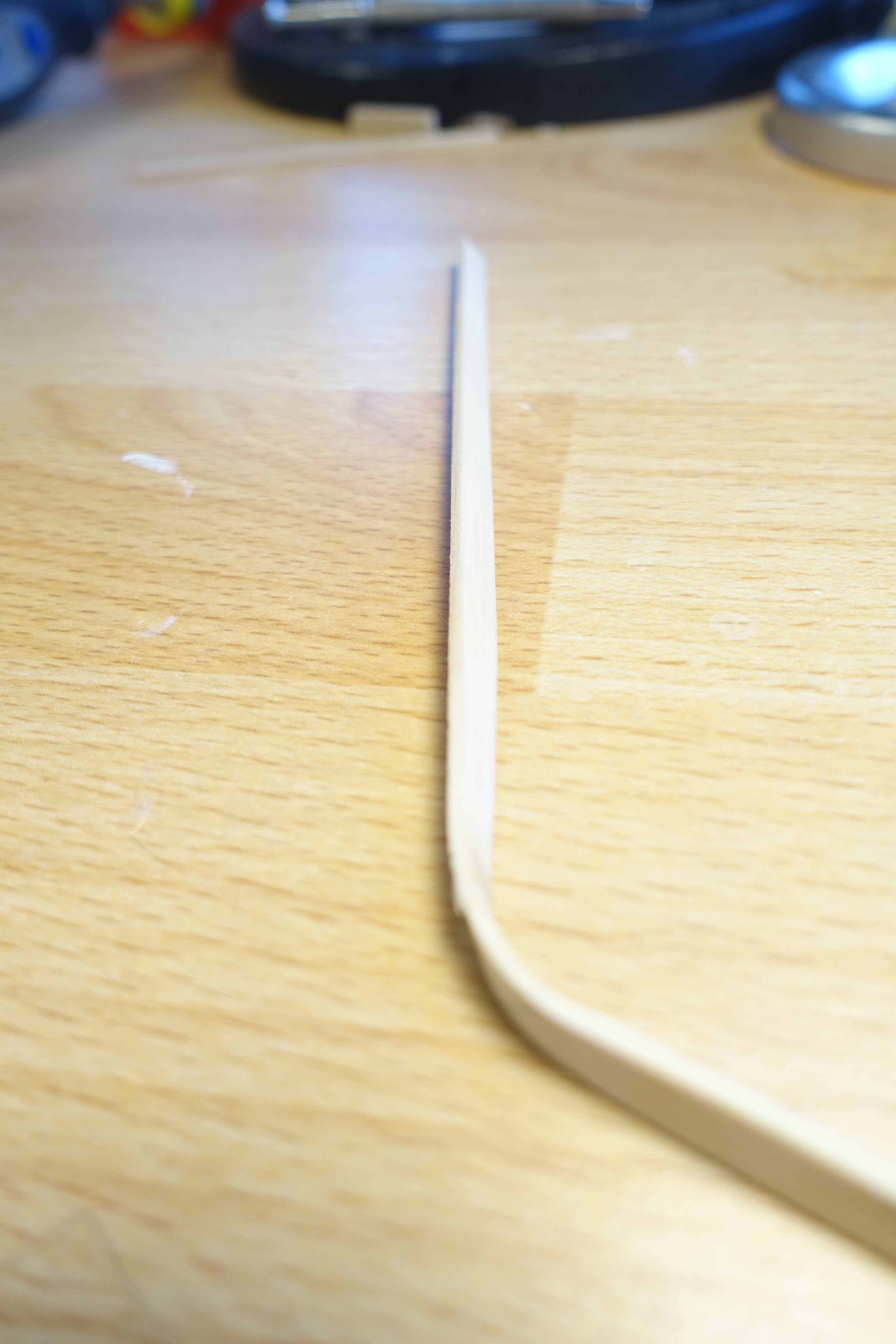
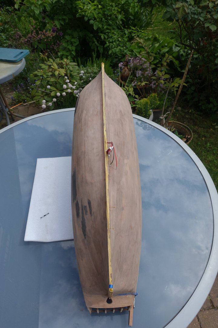
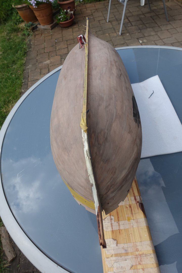
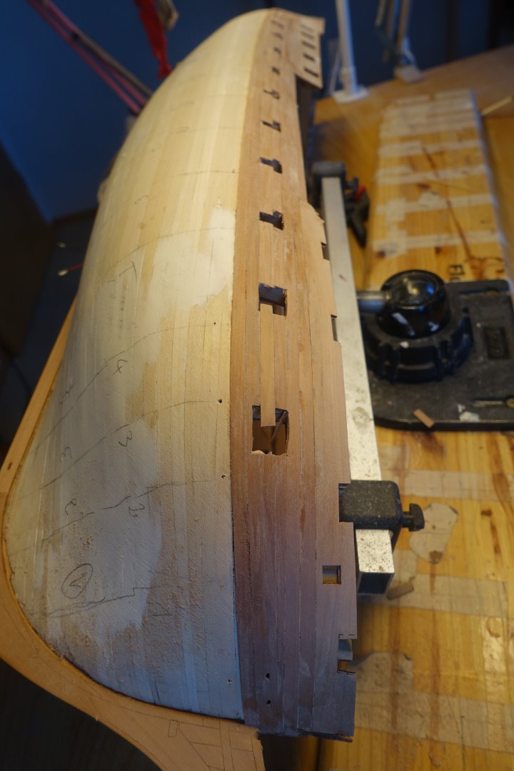
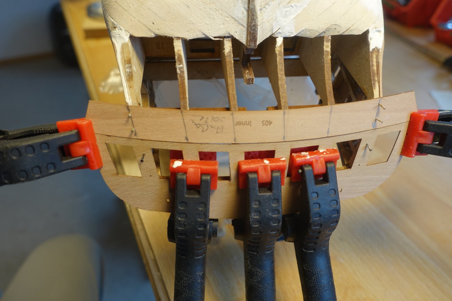
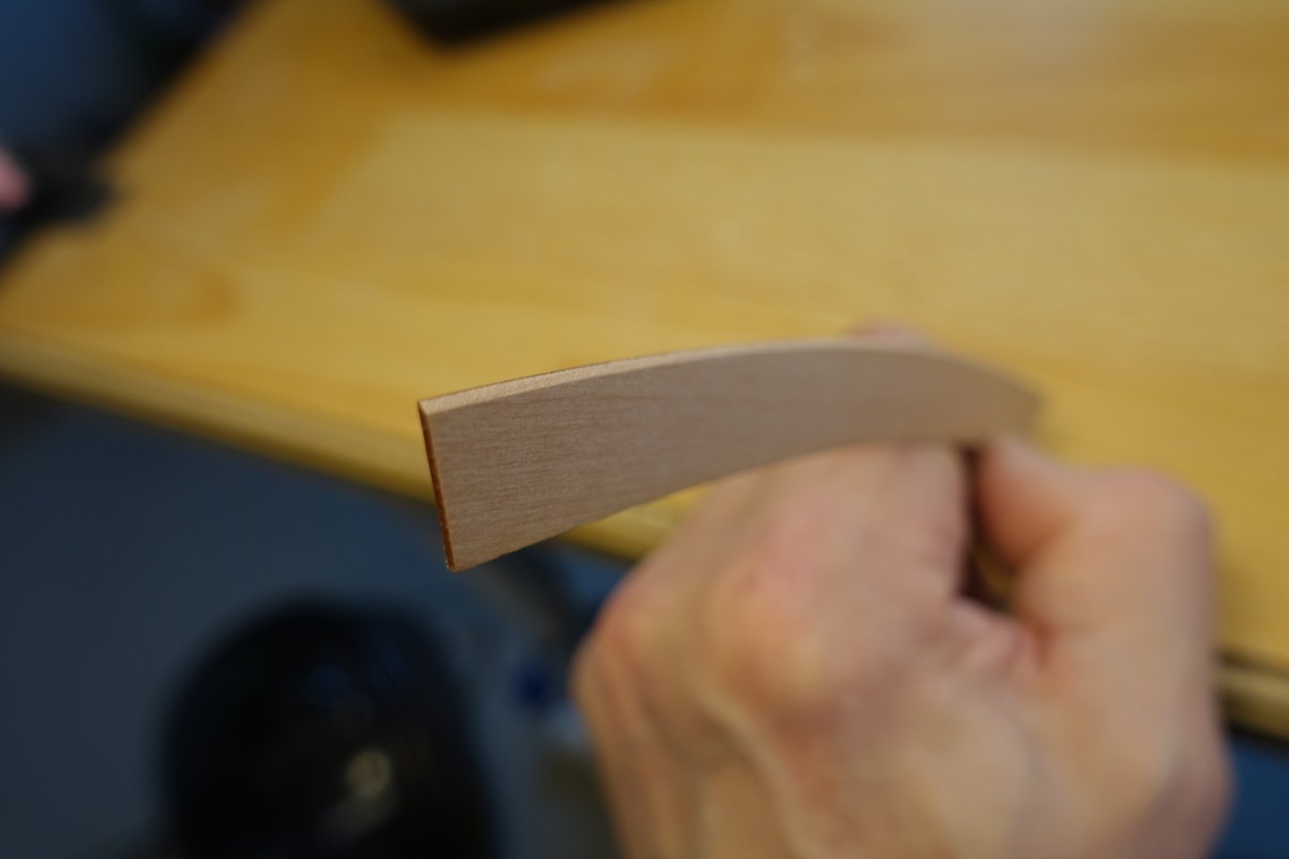
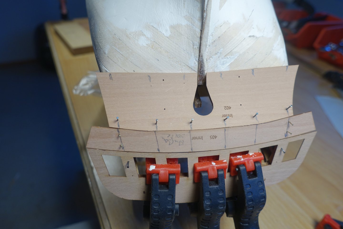
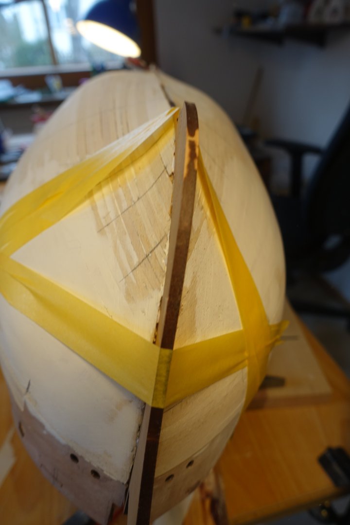
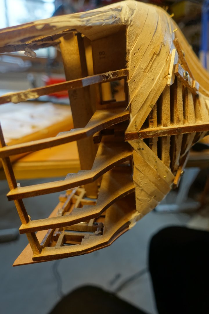
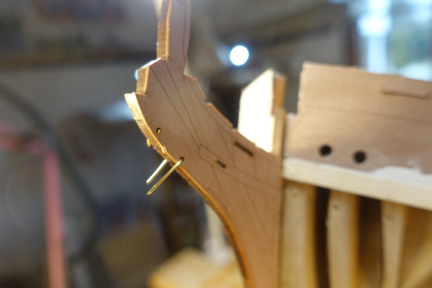
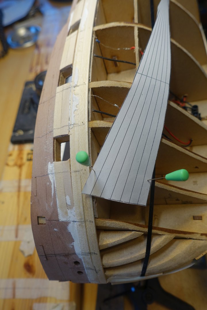
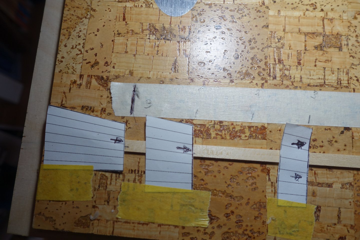
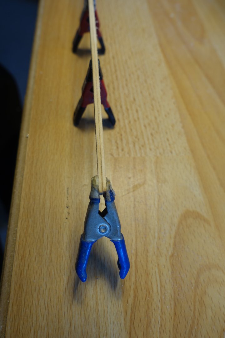
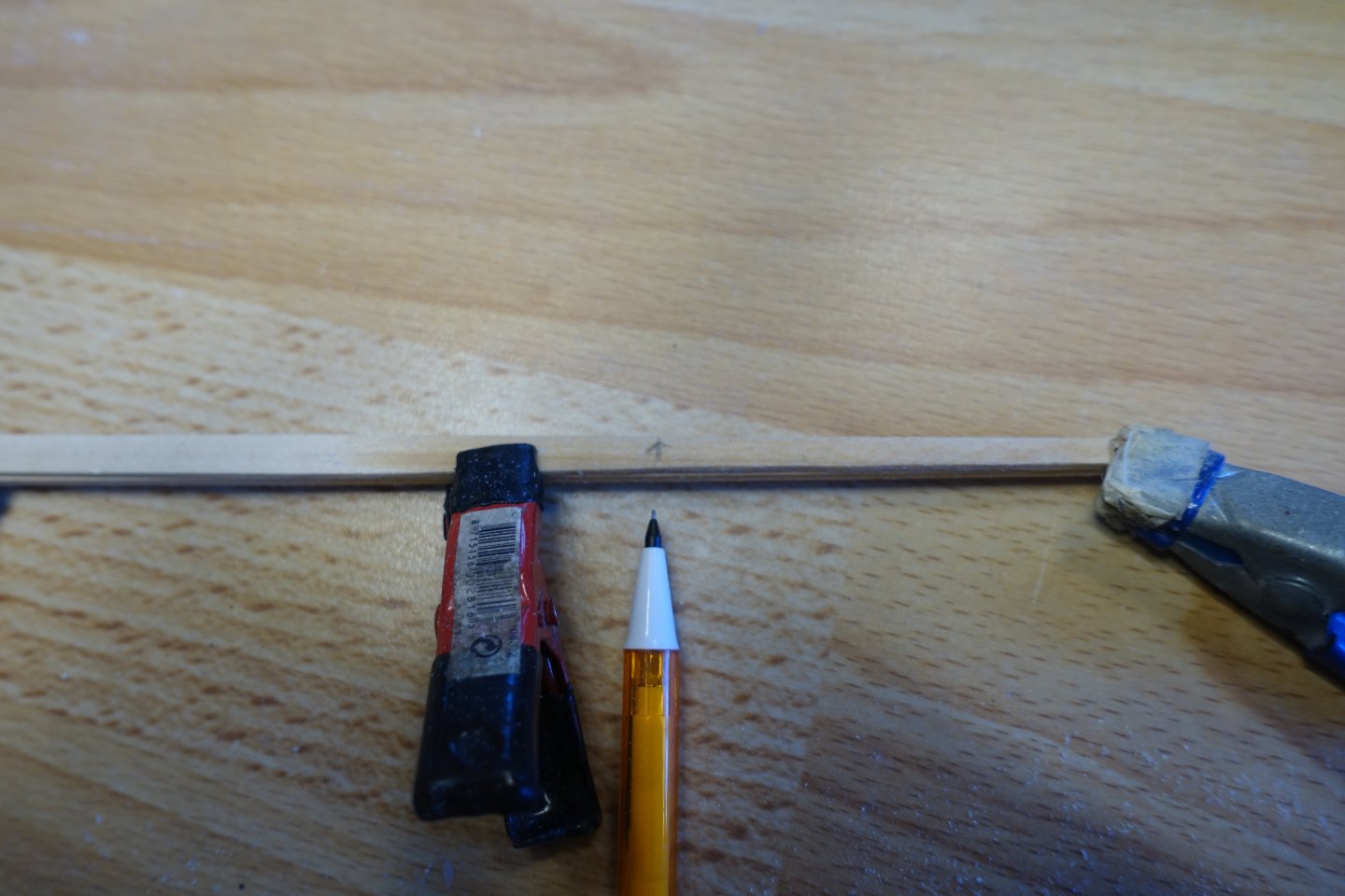
In my opinion, the most difficult part is adjusting the planks at the stern. First, I created a template to capture the bevelling at the stern post. A plank was held up and marked where the bend begins (see thin pencil lines) The plank was then hot bent The bend in the longitudinal direction was made with the fingers 4289 Subsequently, the bevelling at the stern post was transferred and the strip was then attached. In the beginning I wanted to lay 7 strips in this way, but then I interrupted after 6 strips and measured the remaining distance to the garboard strake. It was already clear that the stern area would also need to be slightly tapered. For the next section, I calculated with 6 planks and used the marking tape to show the course. Here, too, it can be seen that the bow area needs to be tapered more. As before: measuring the distances between the frames using painter's tape. Gluing the tape onto a board and calculating the plank width using Chuck's planking fan. Two planks of the new section are laid, also tapered at the stern.


-
Hi Tim. Thanks for the encouraging words. Opinions are divided on the planking and everyone has their own method. It always makes me feel good when every strip fits. Clark
-
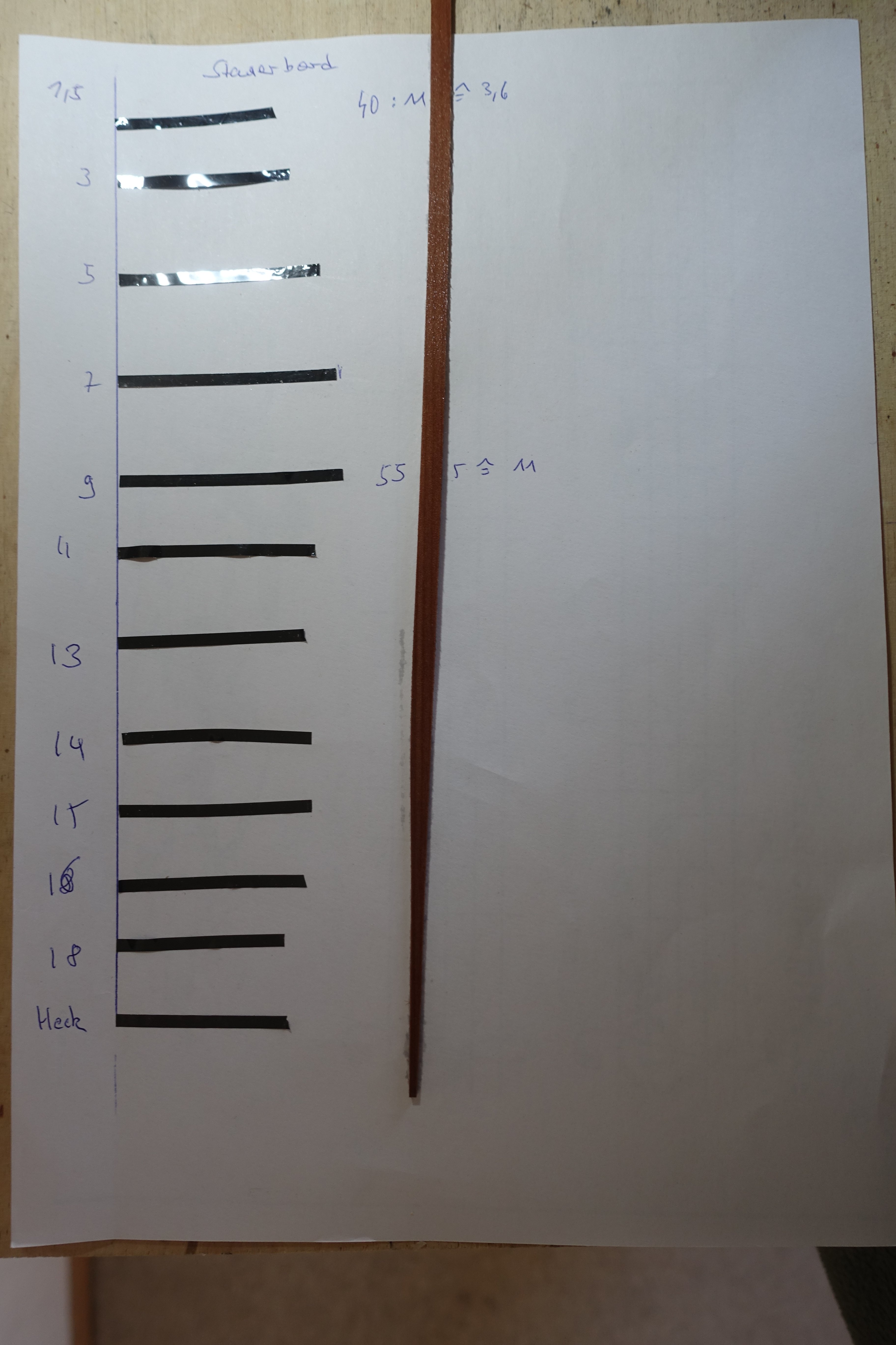
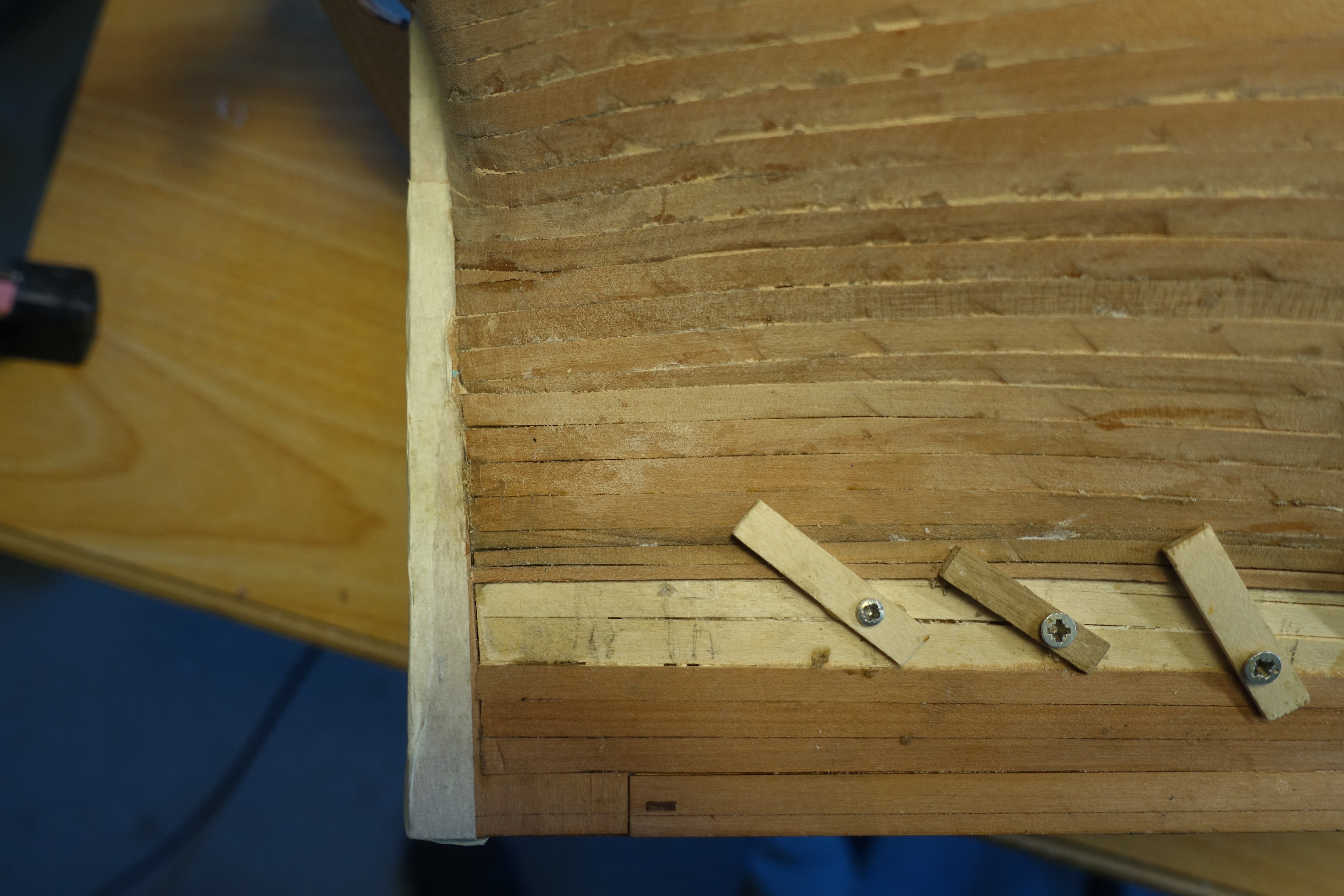
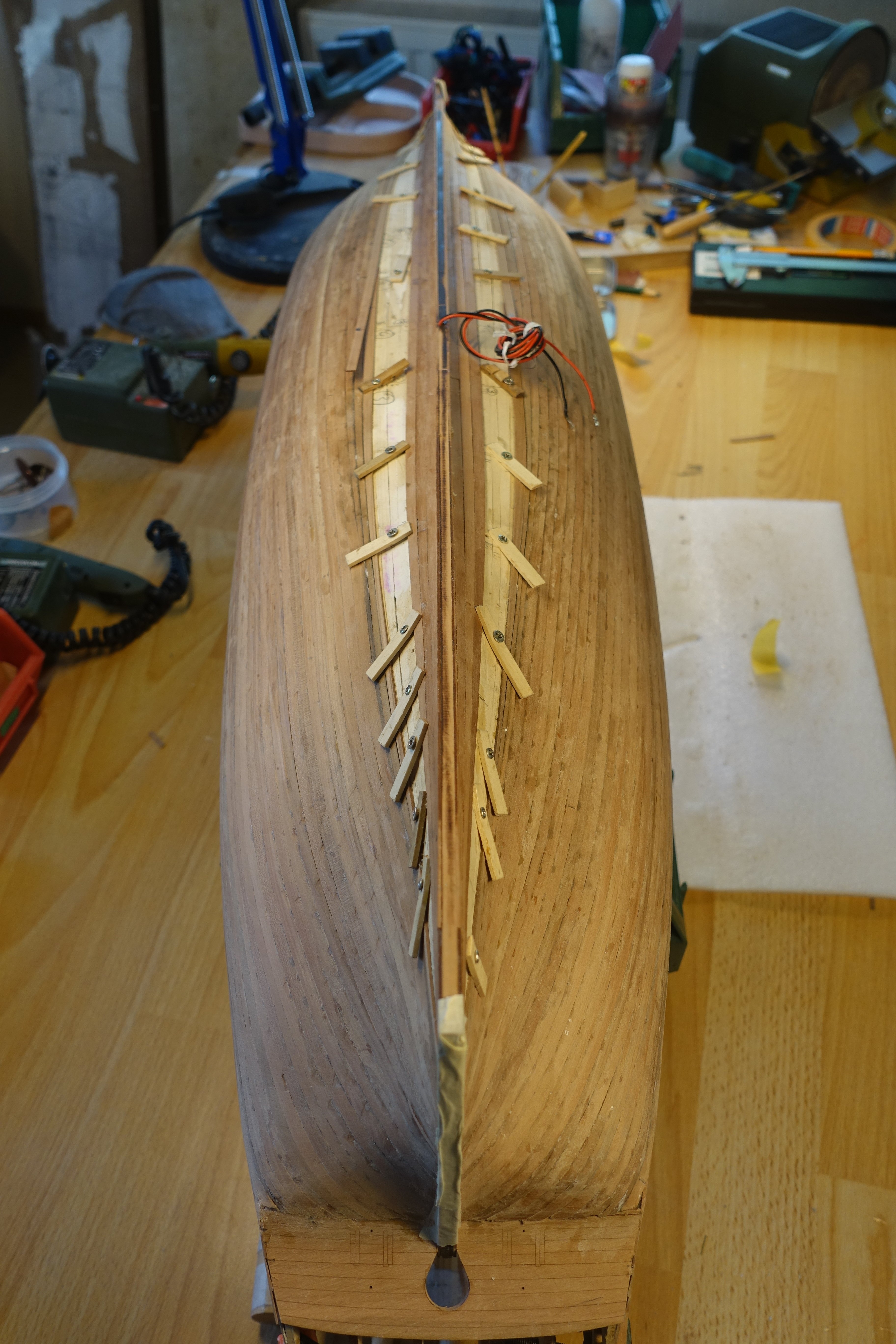
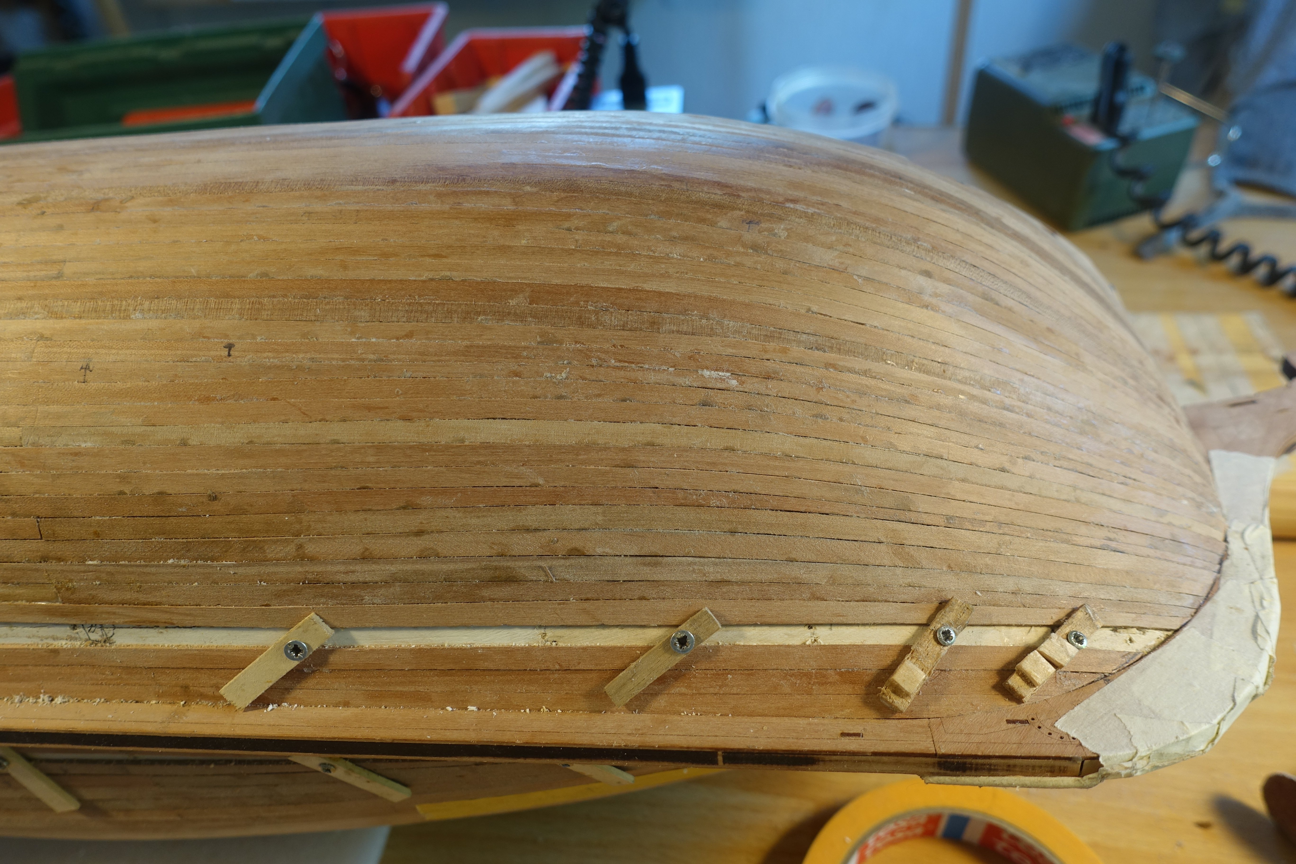
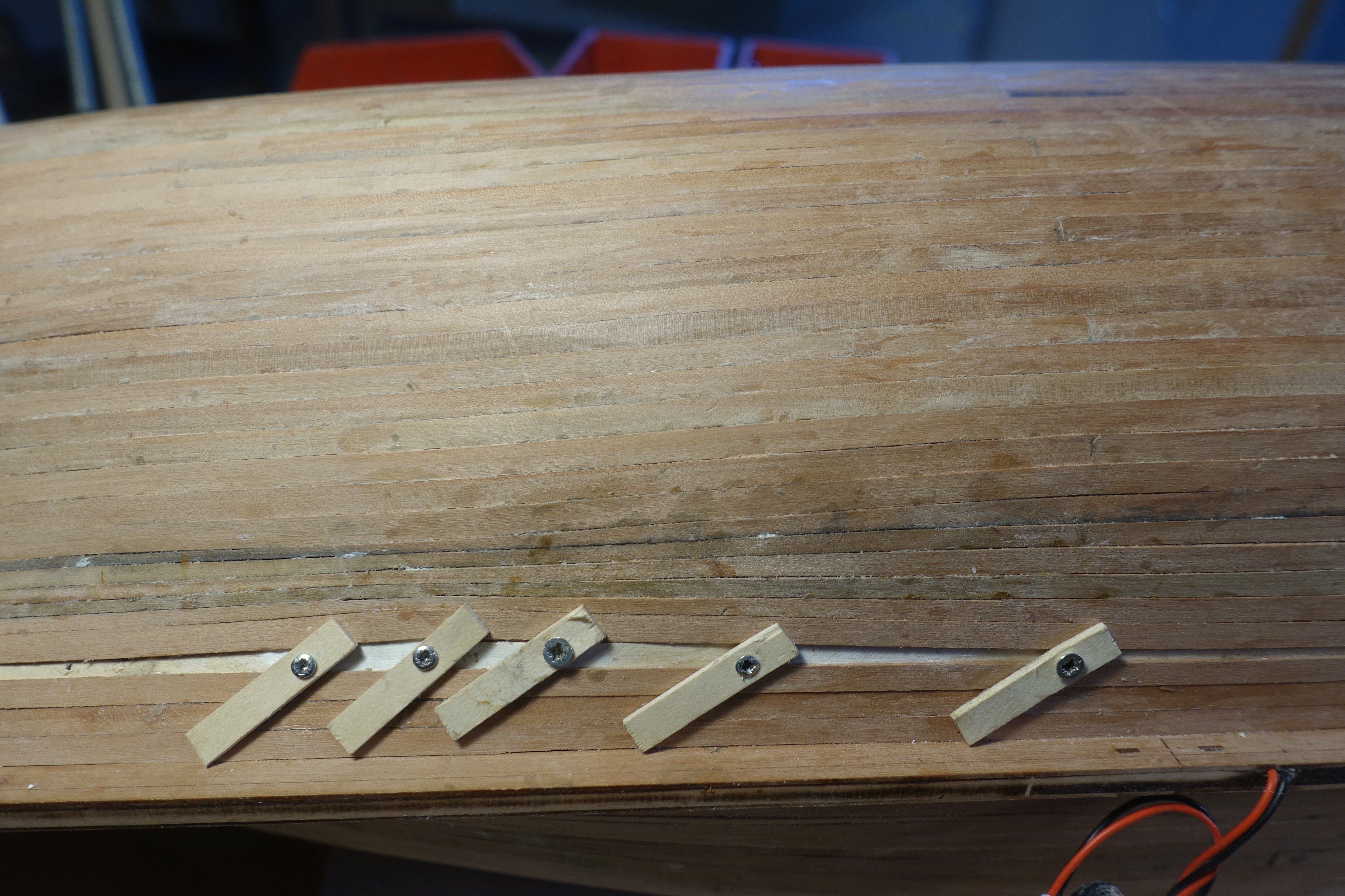
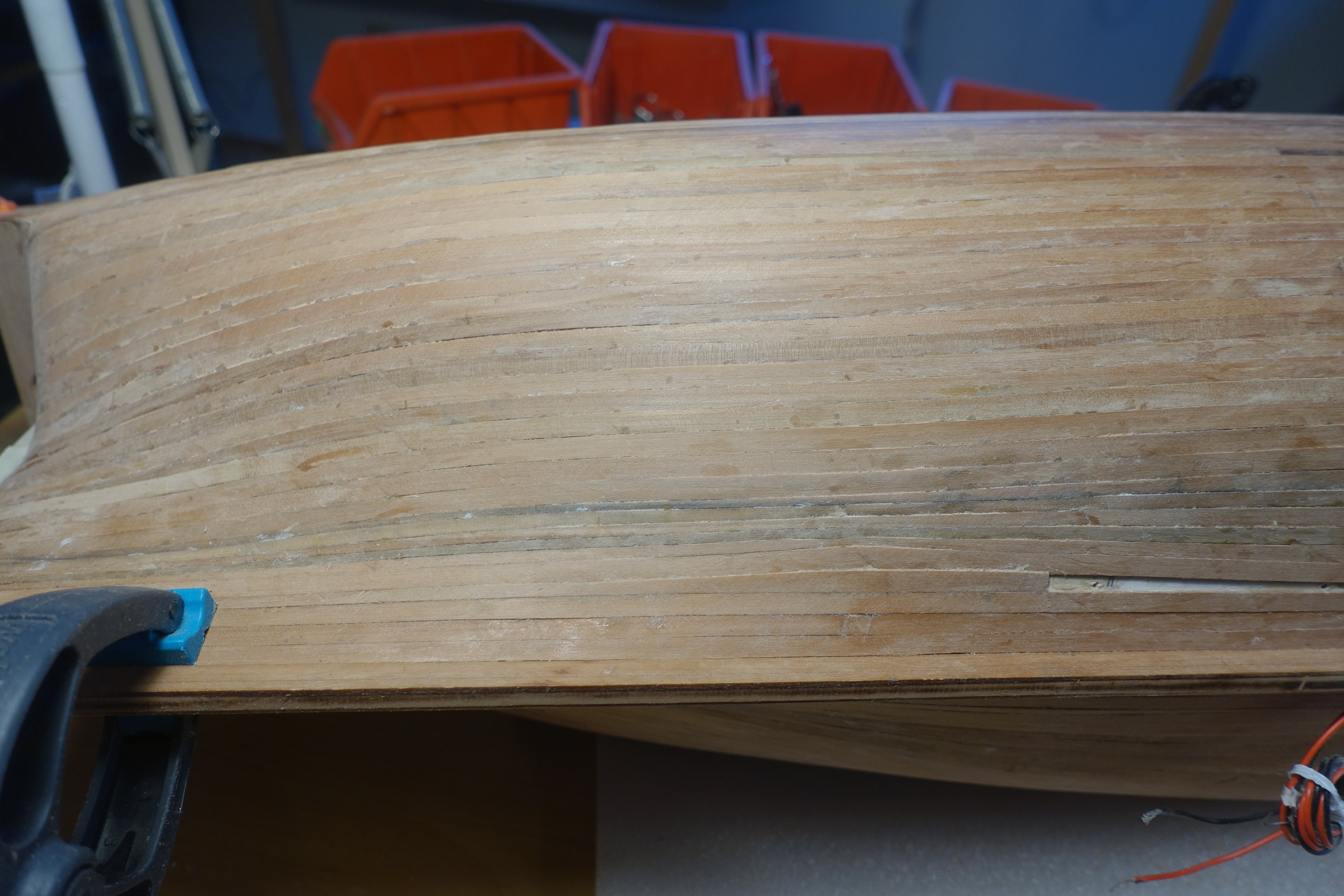
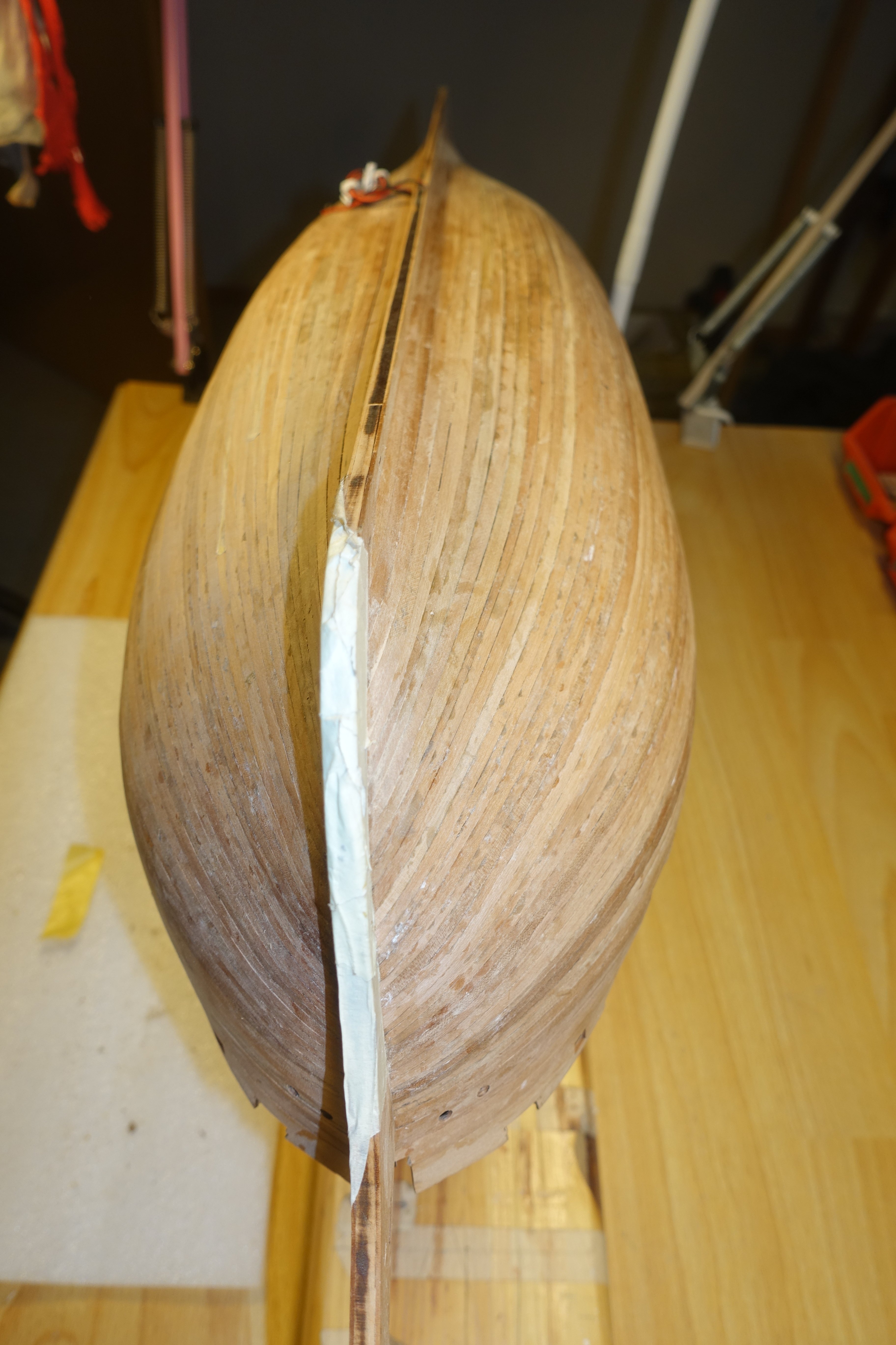
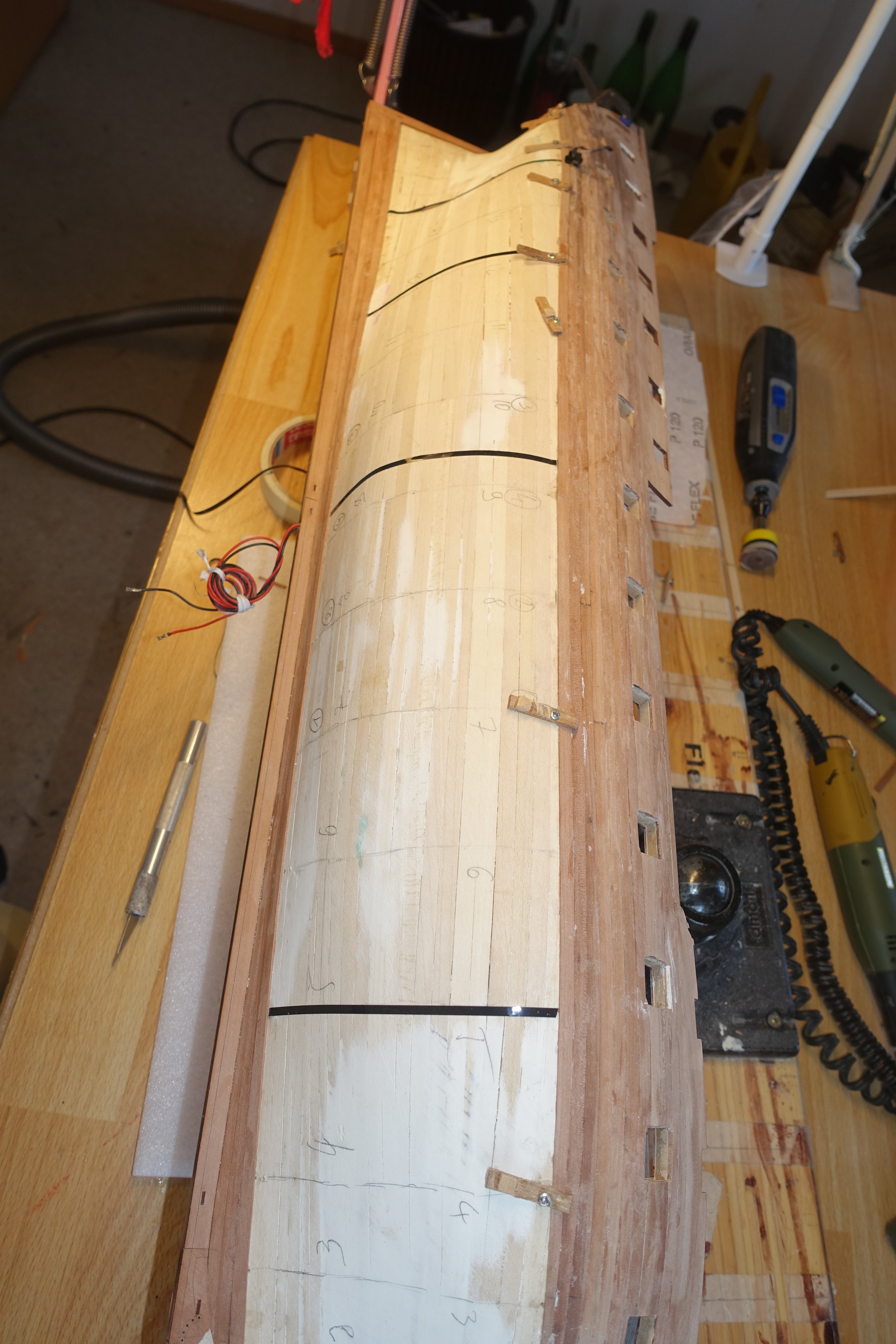
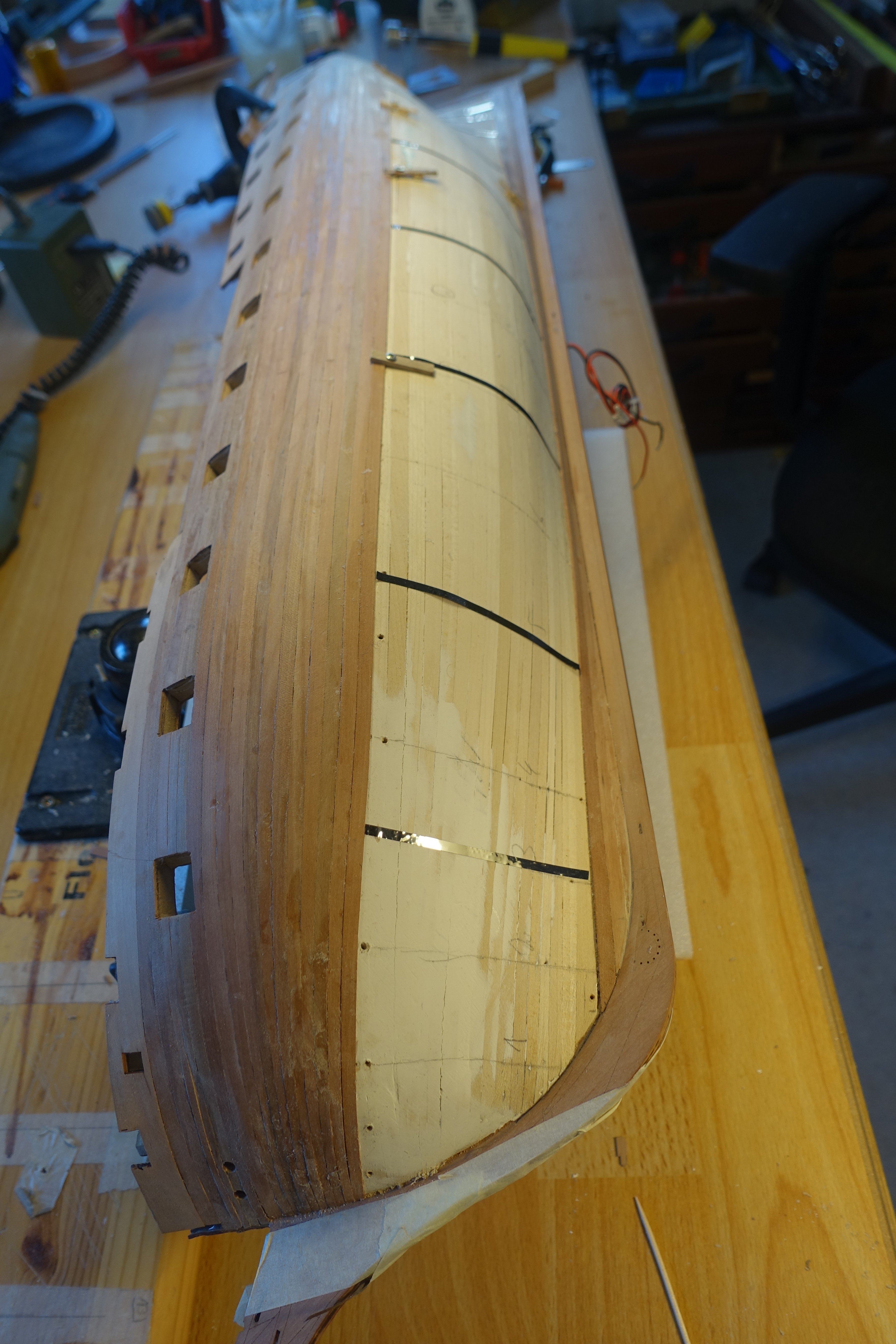
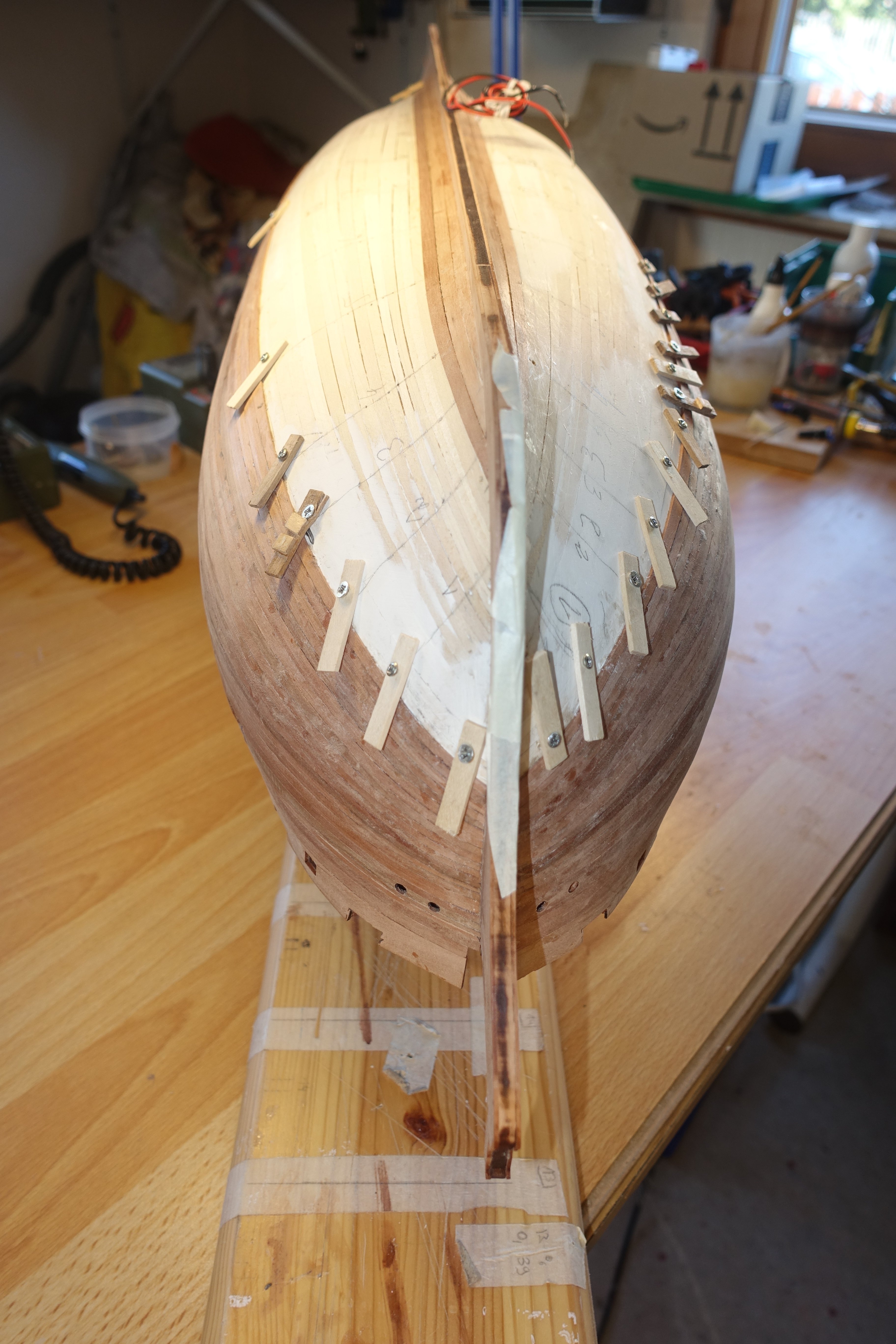
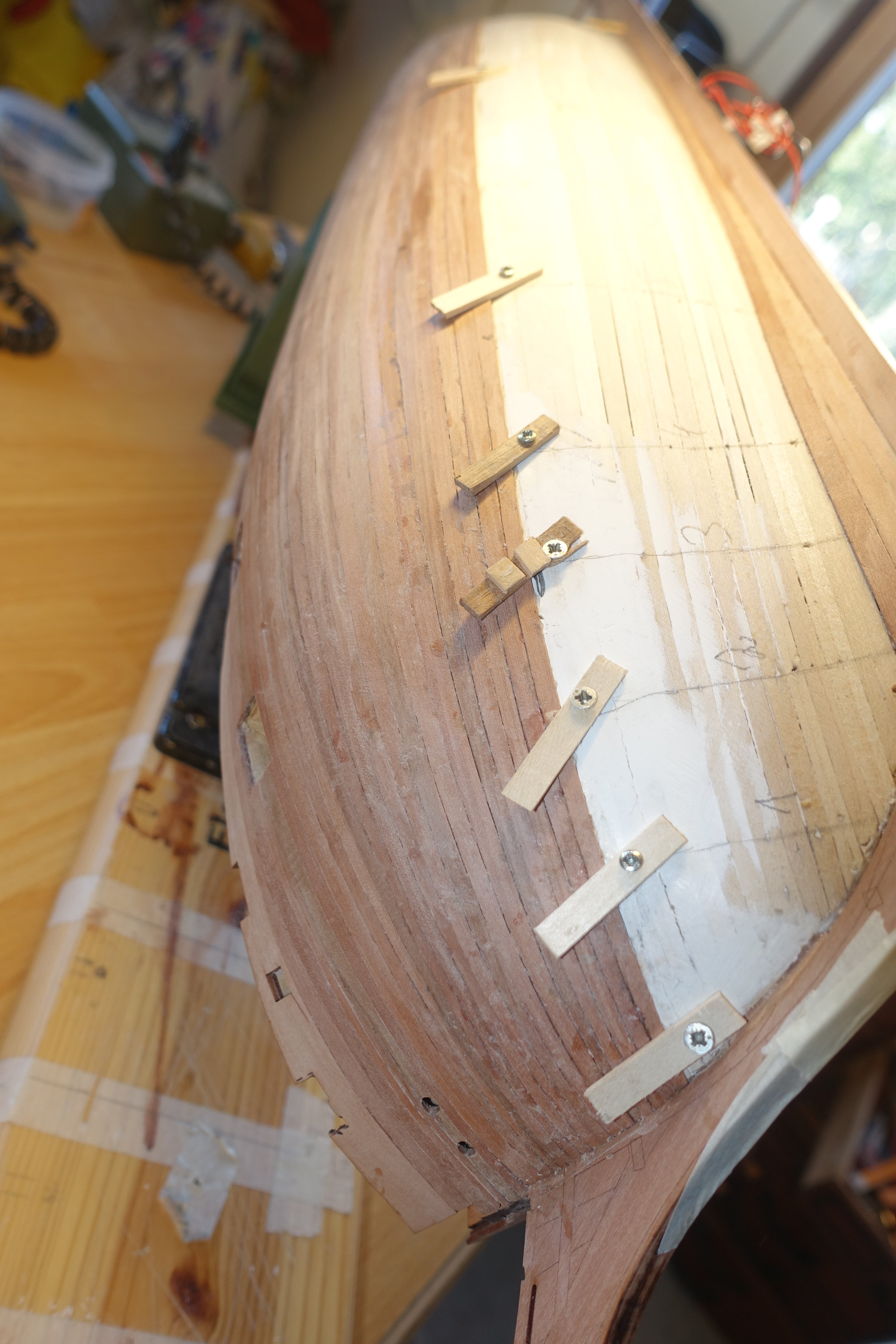
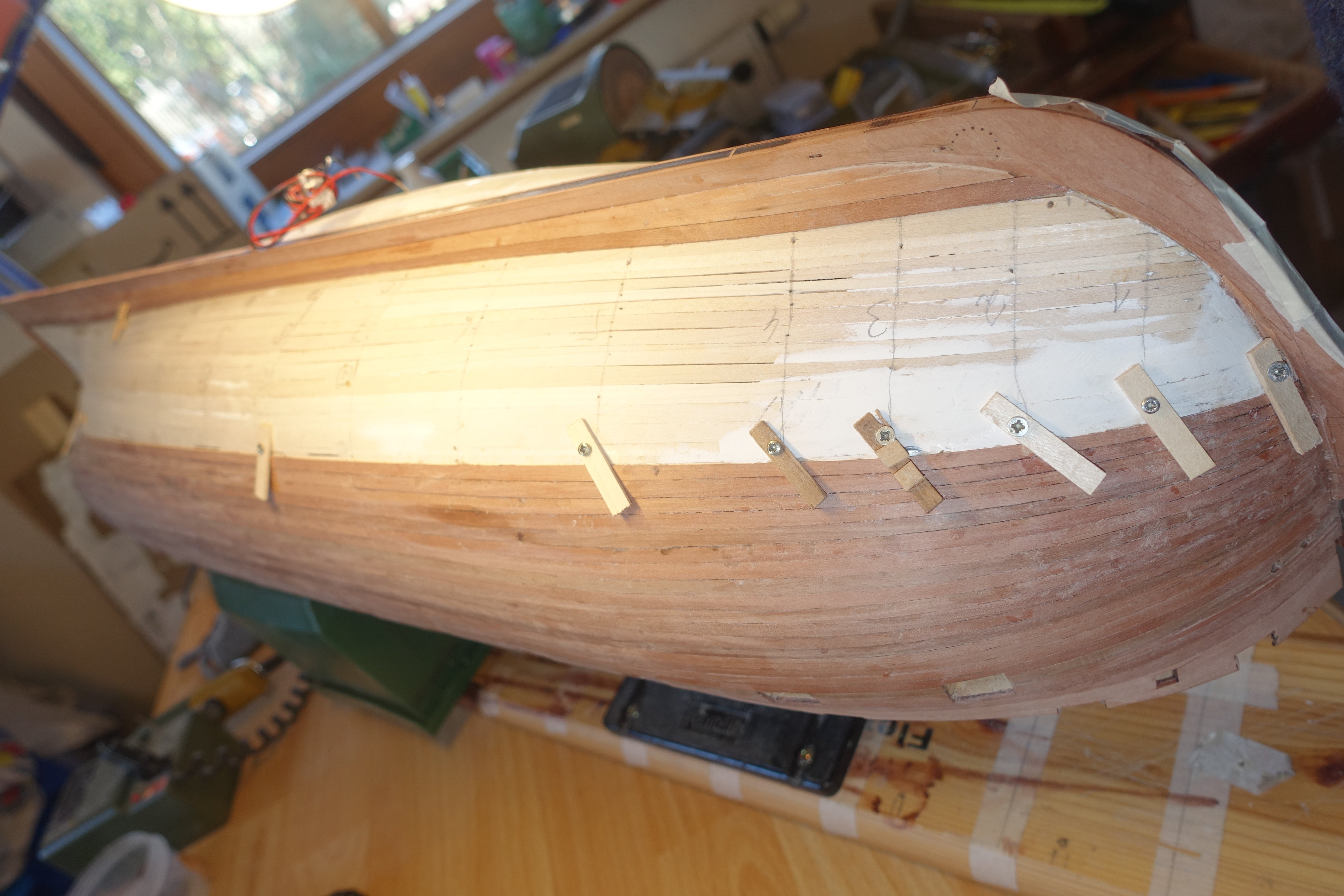
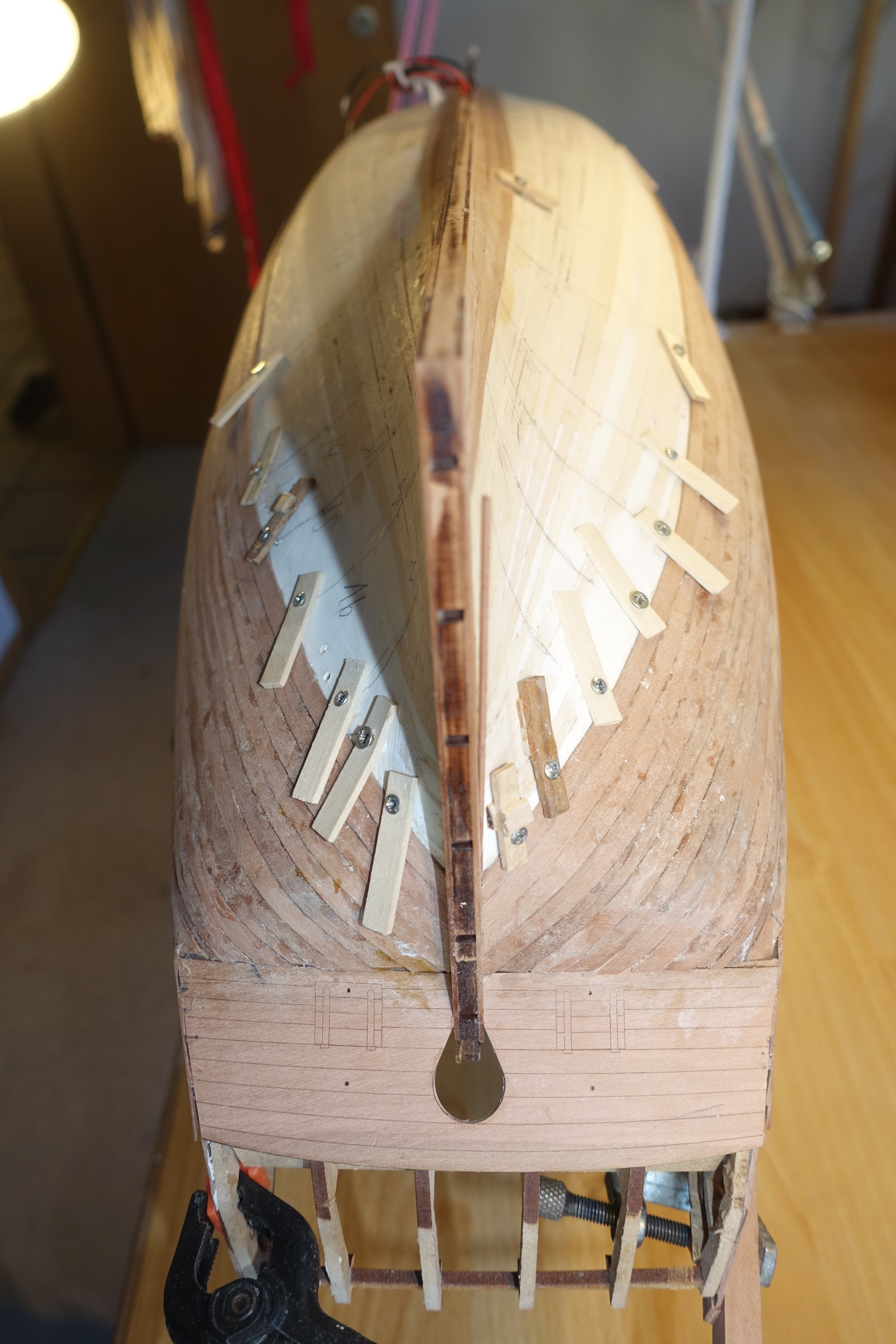
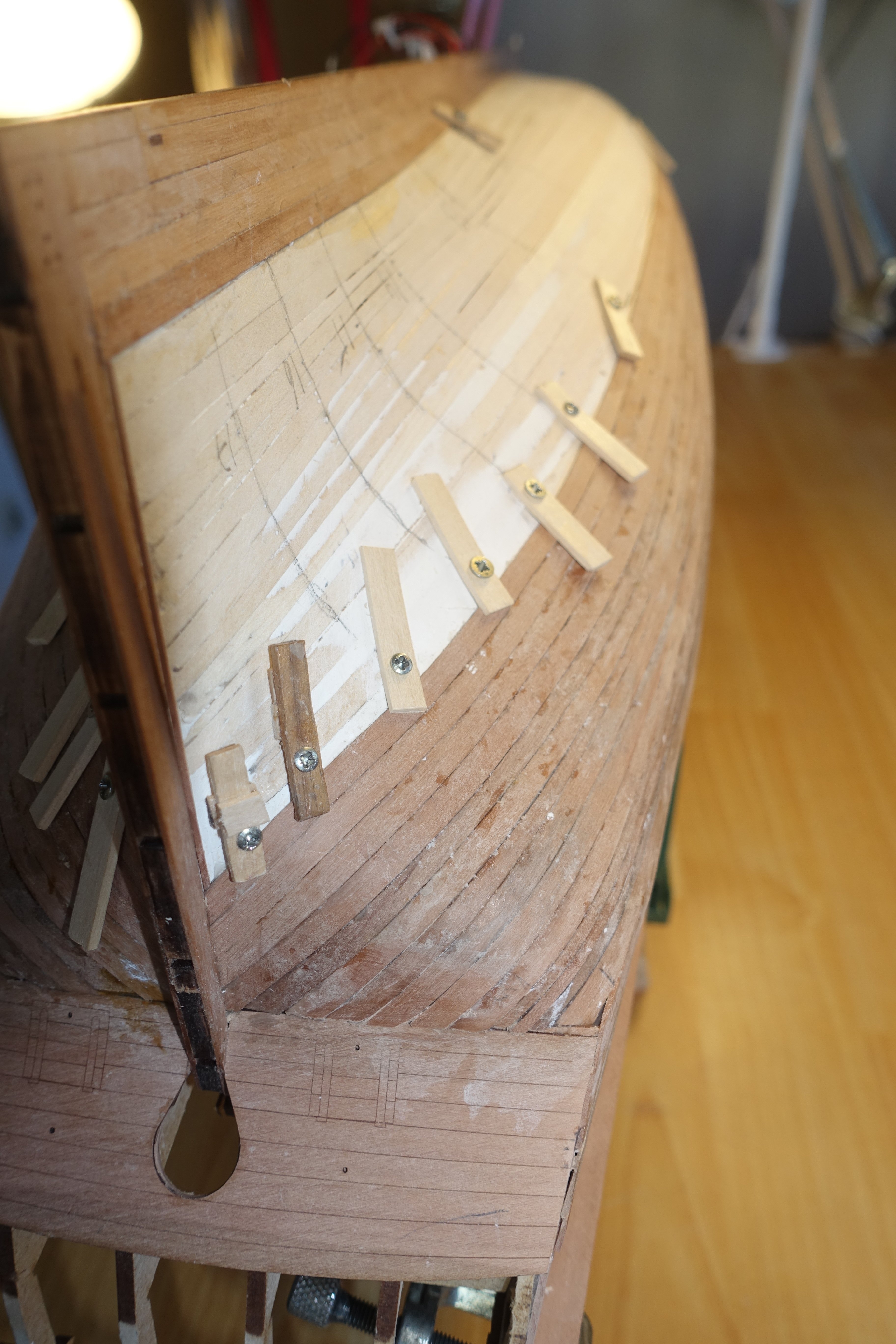
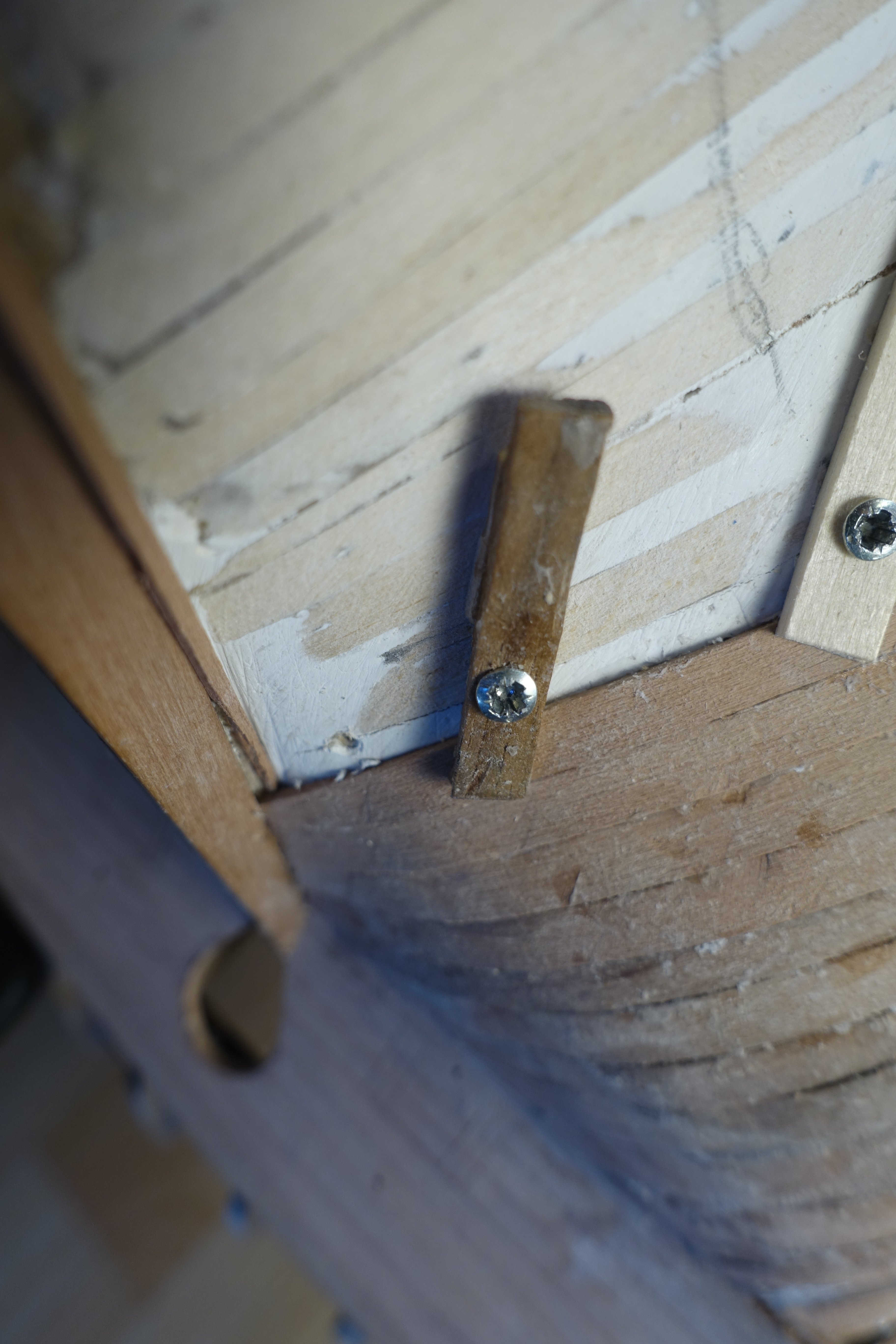
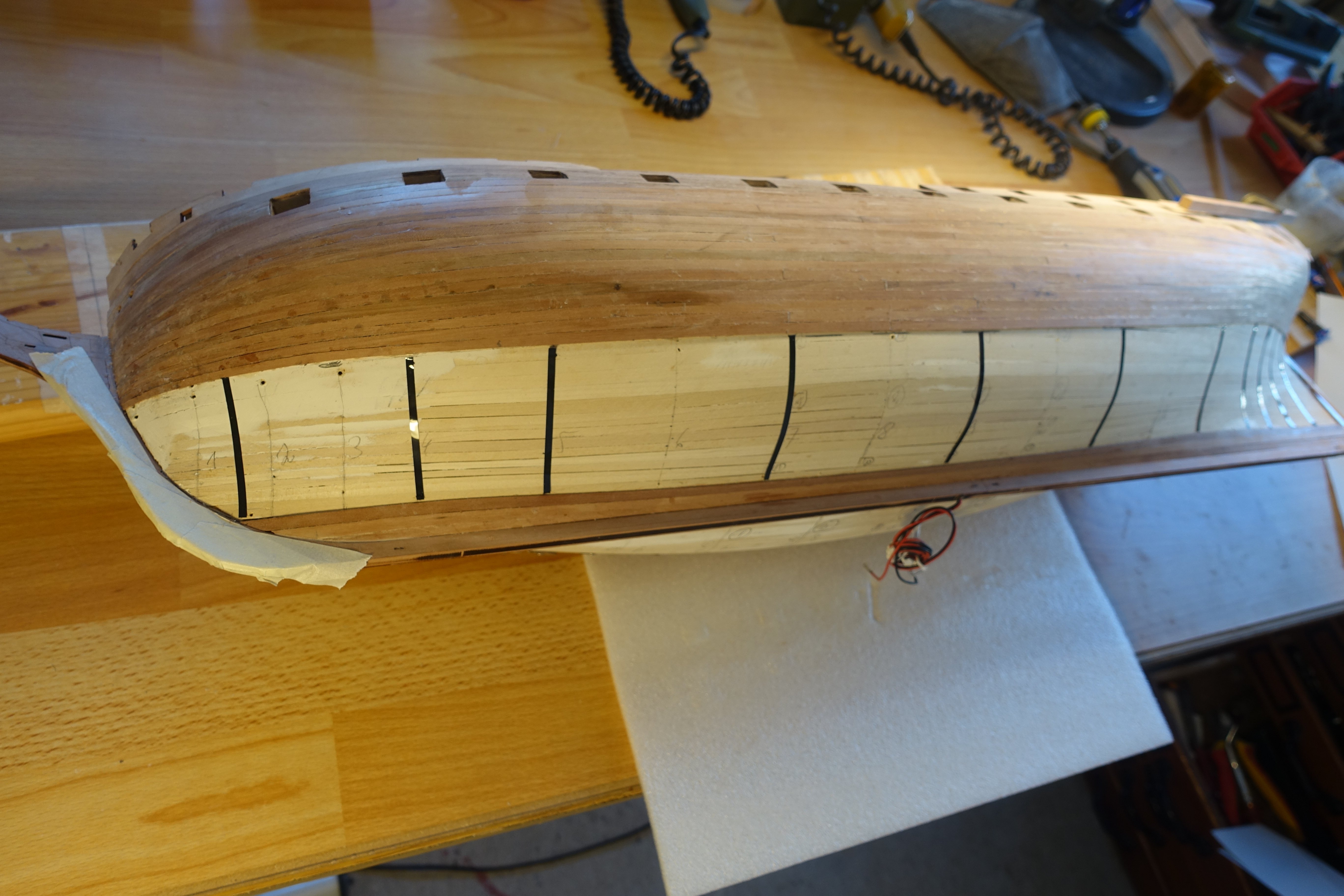
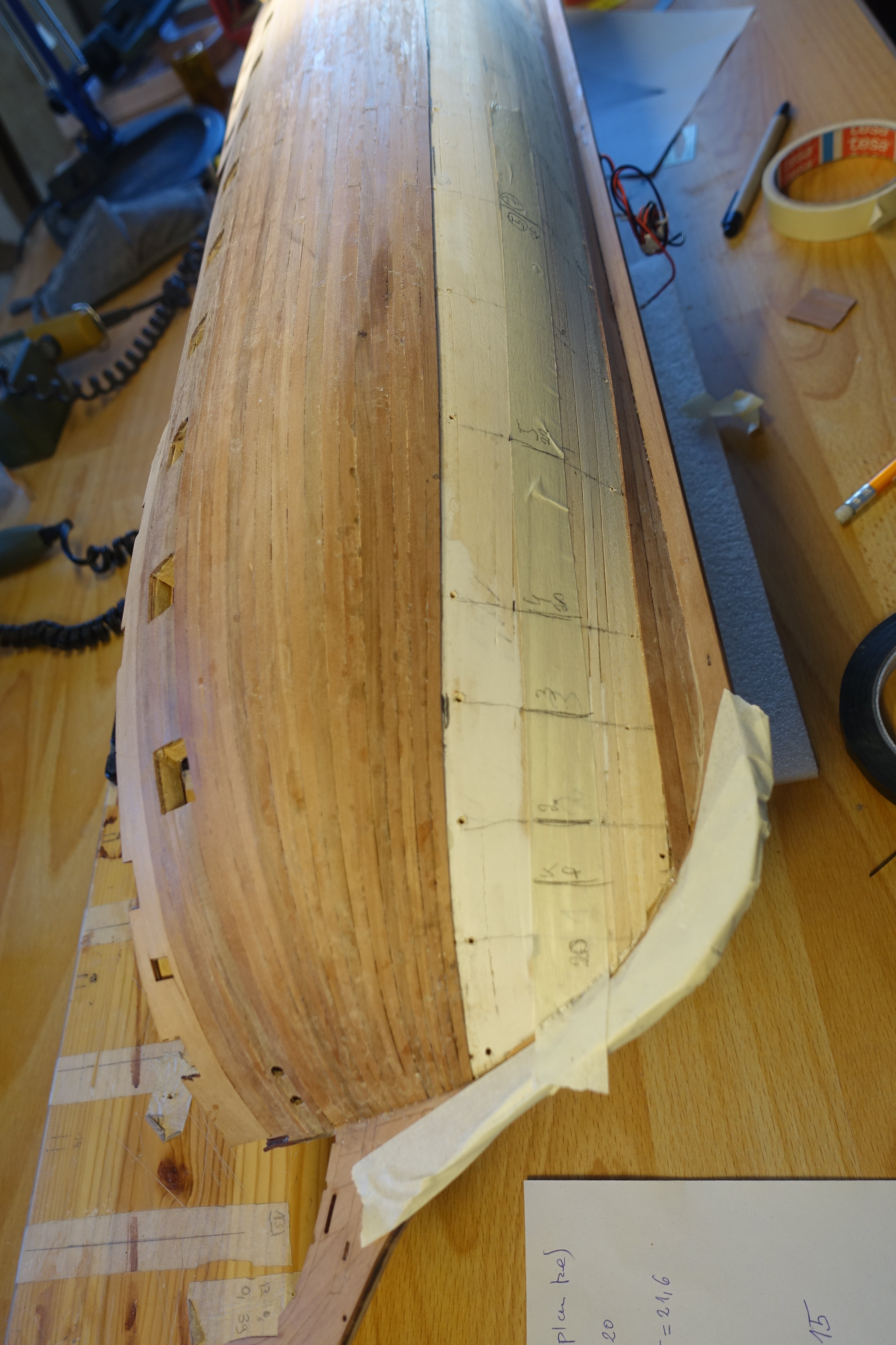
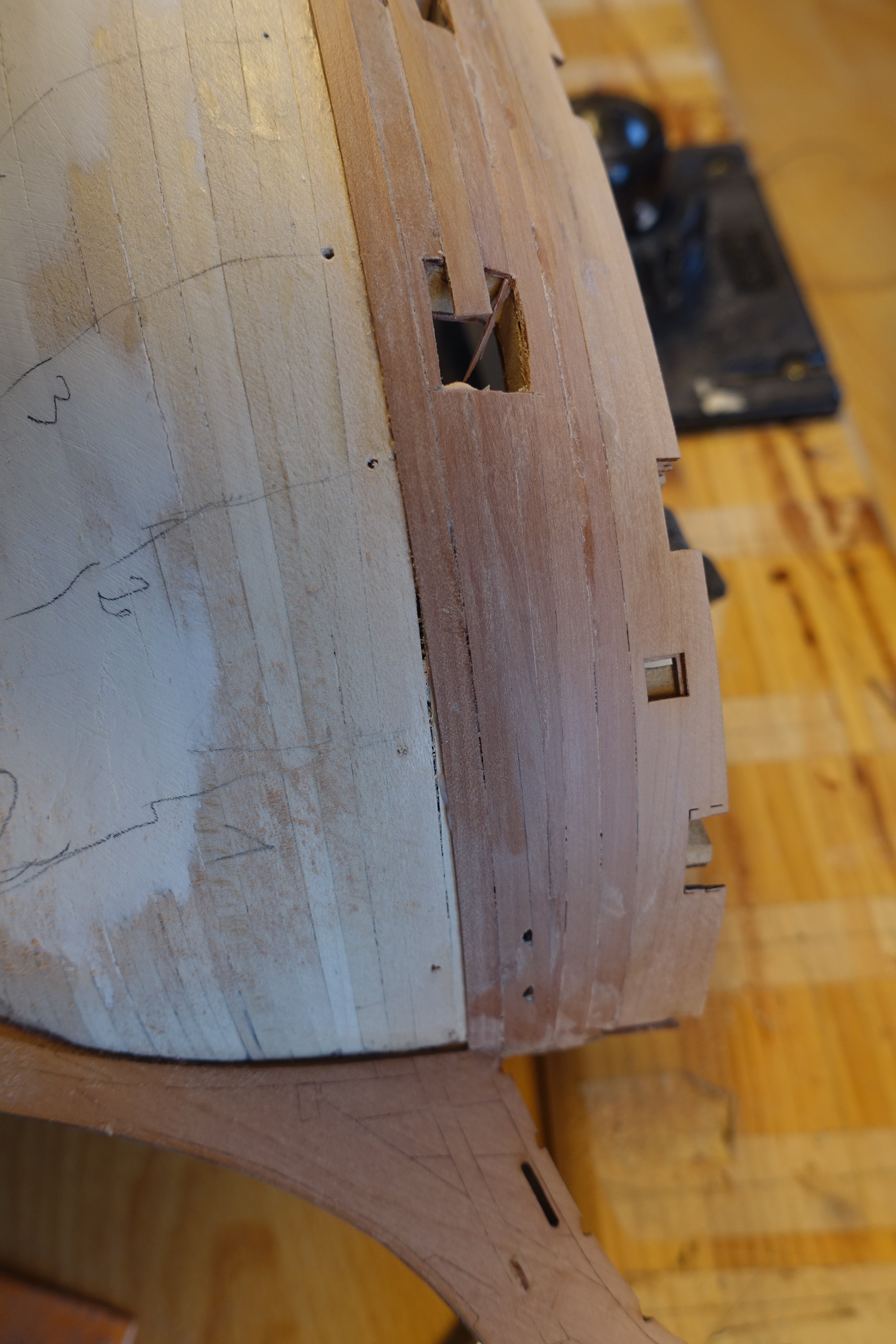
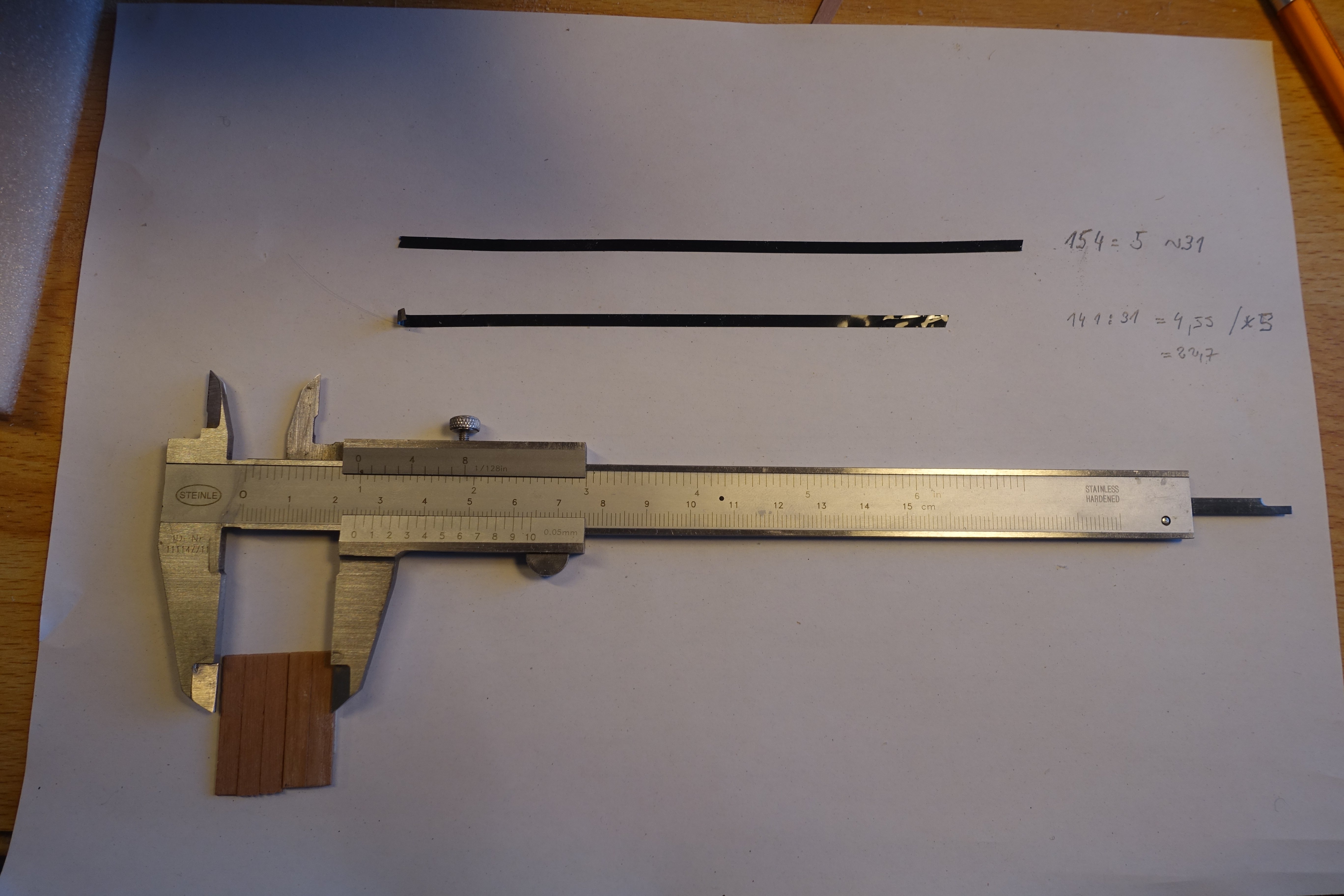
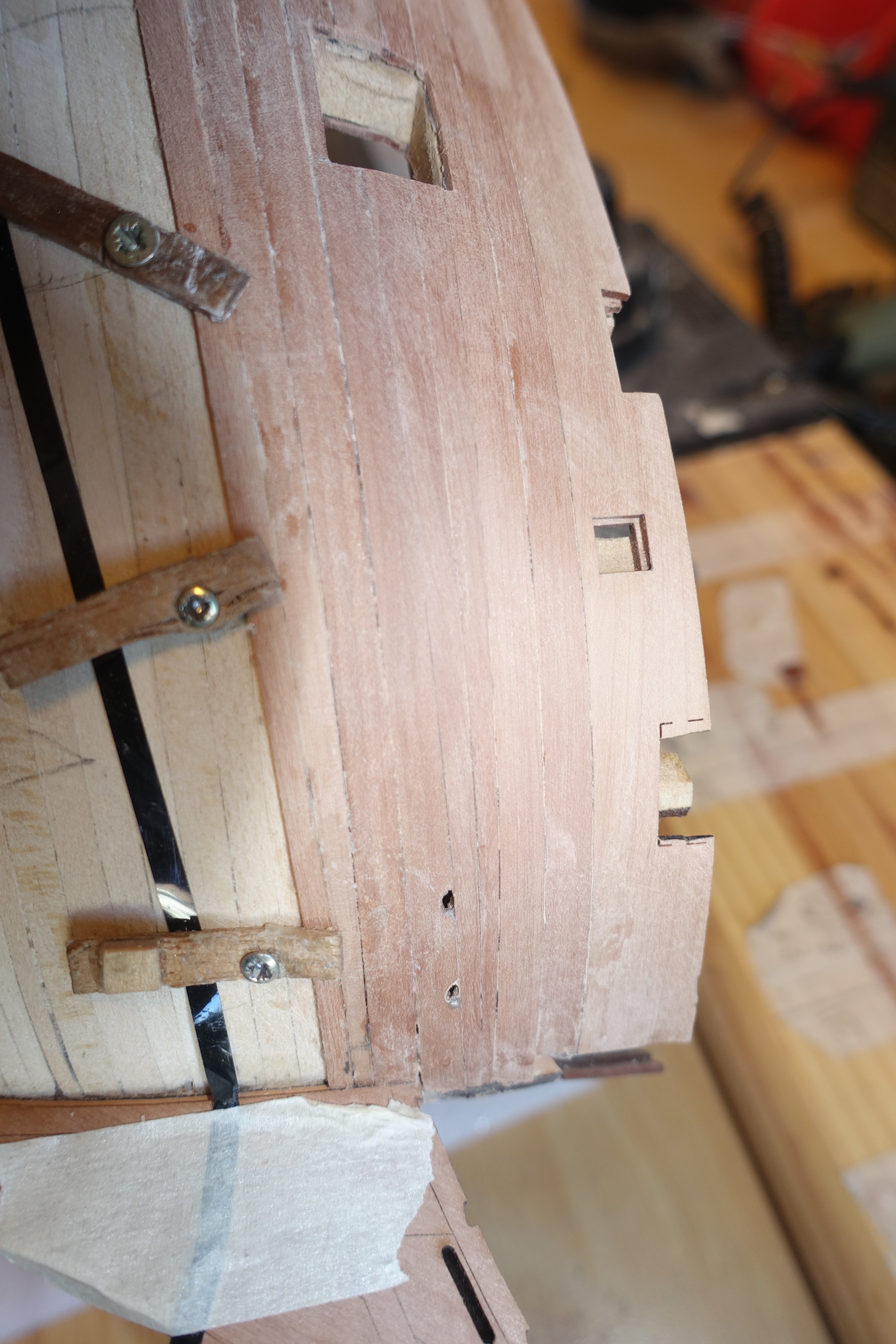
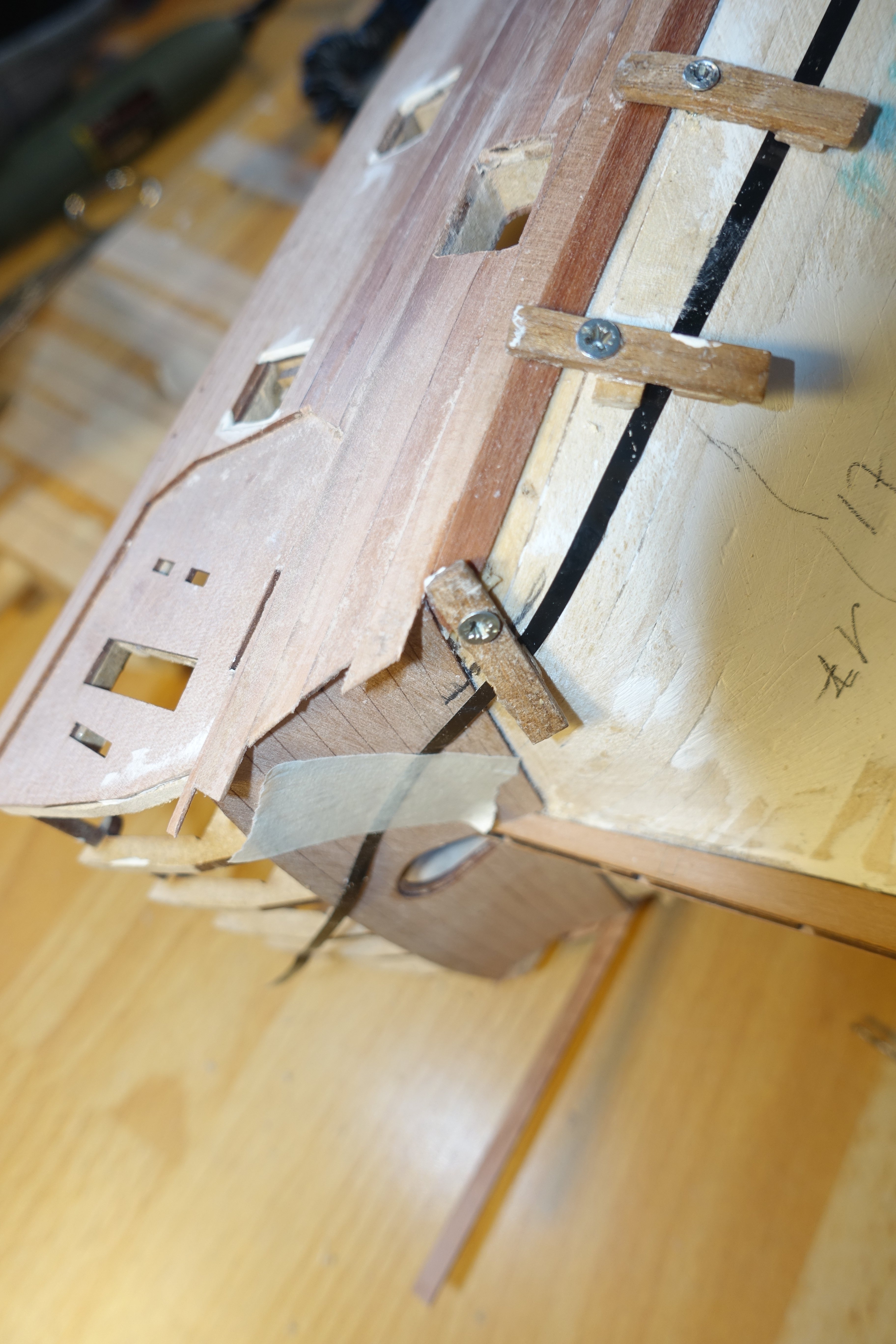
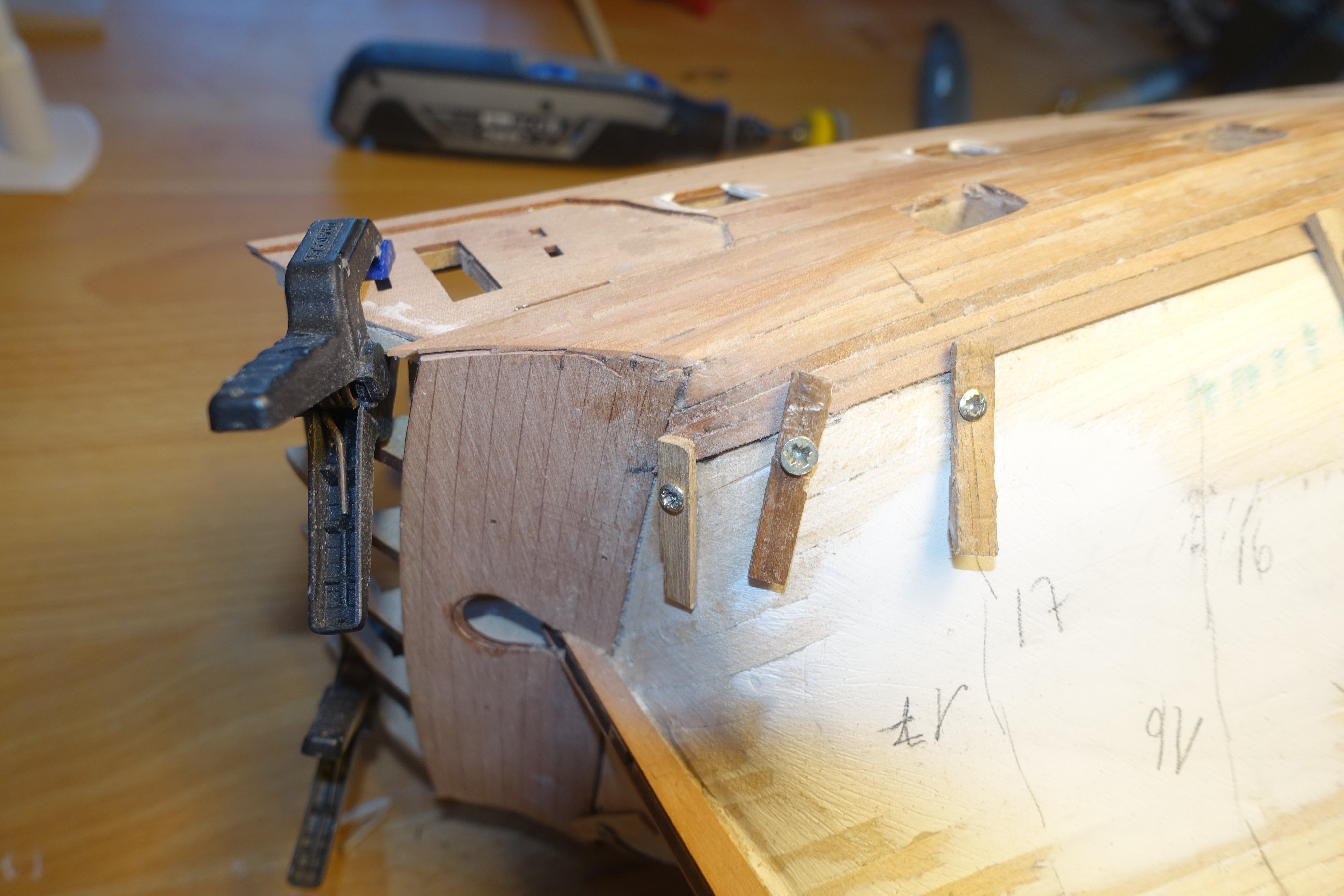
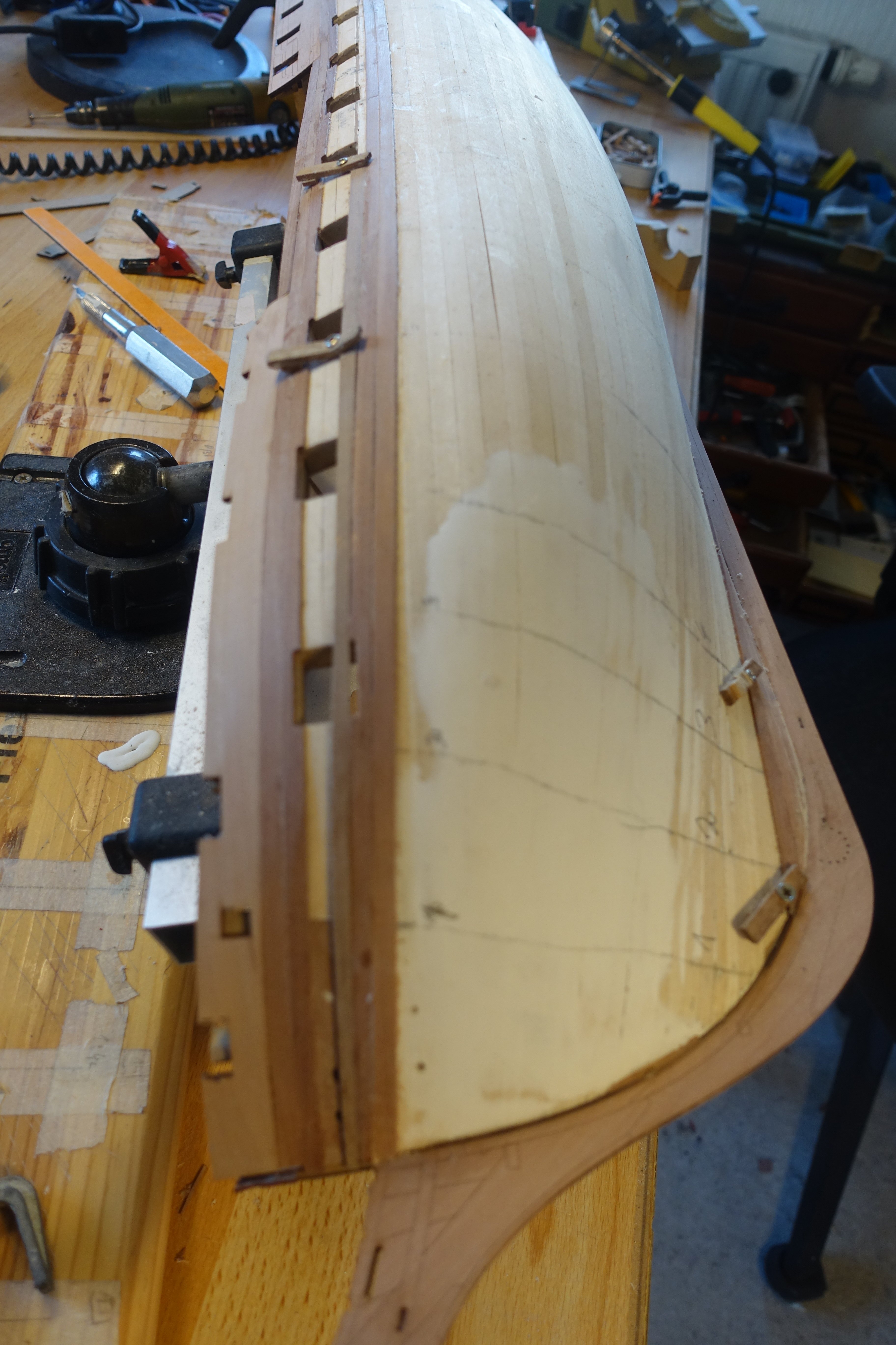
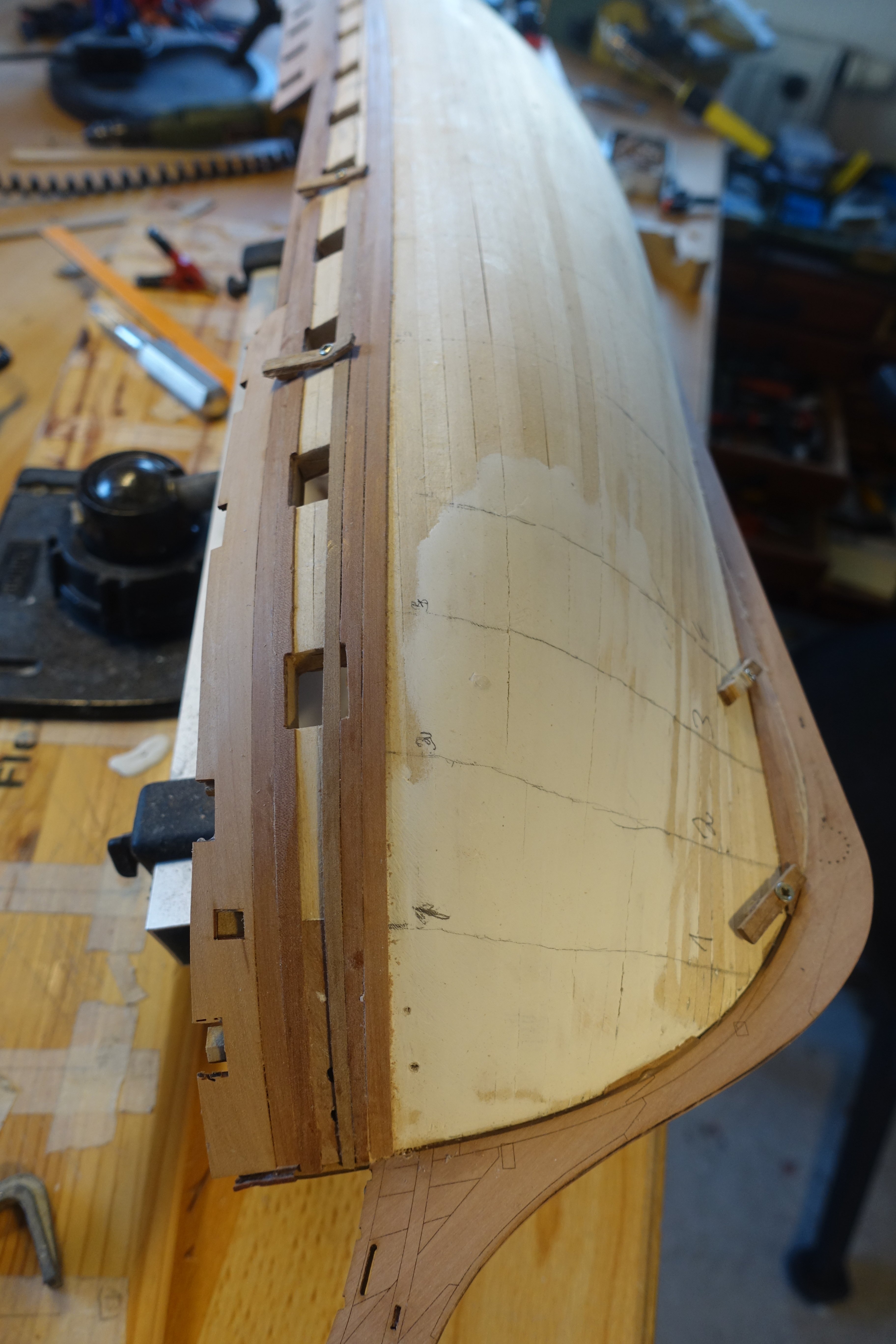
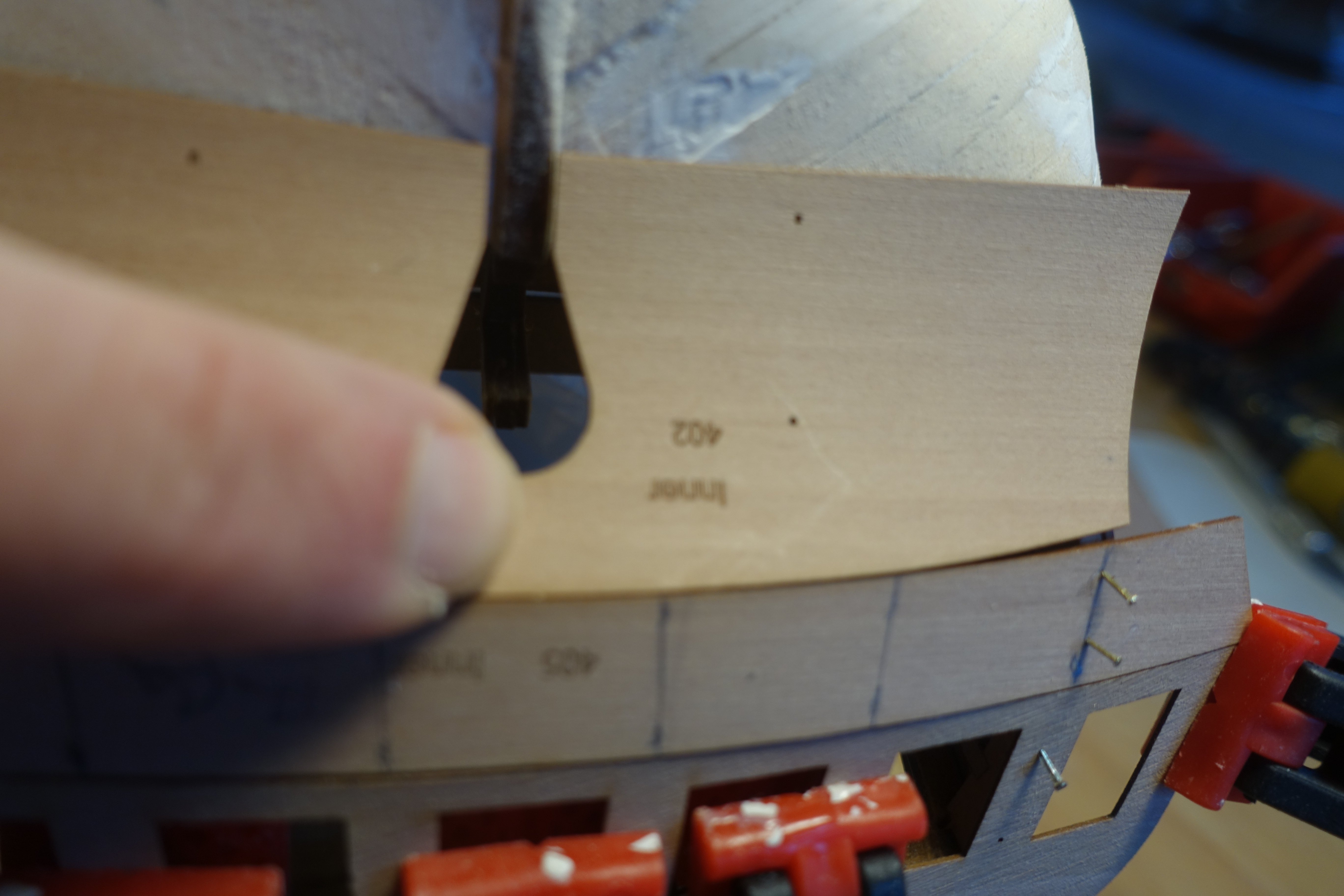
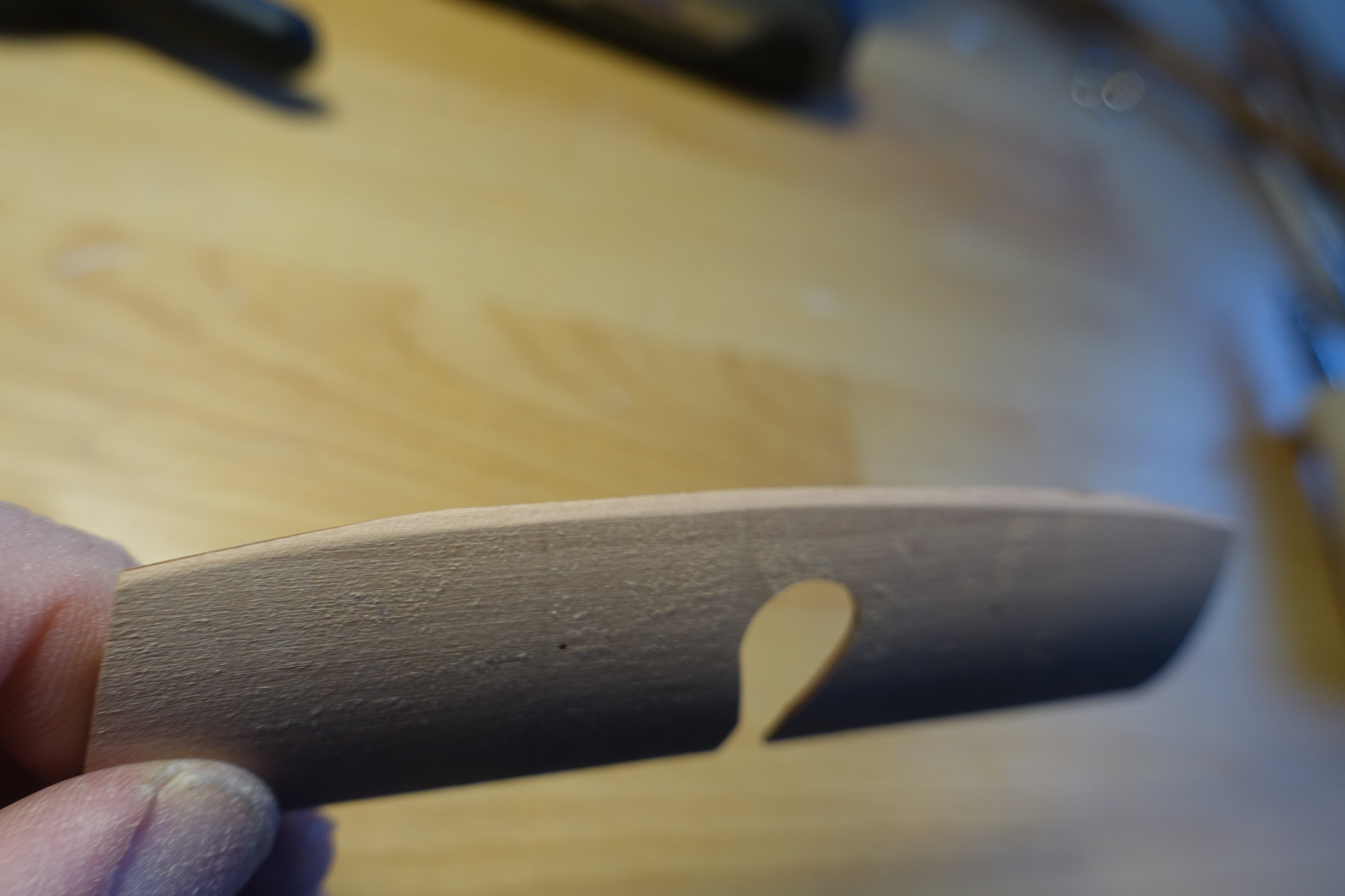
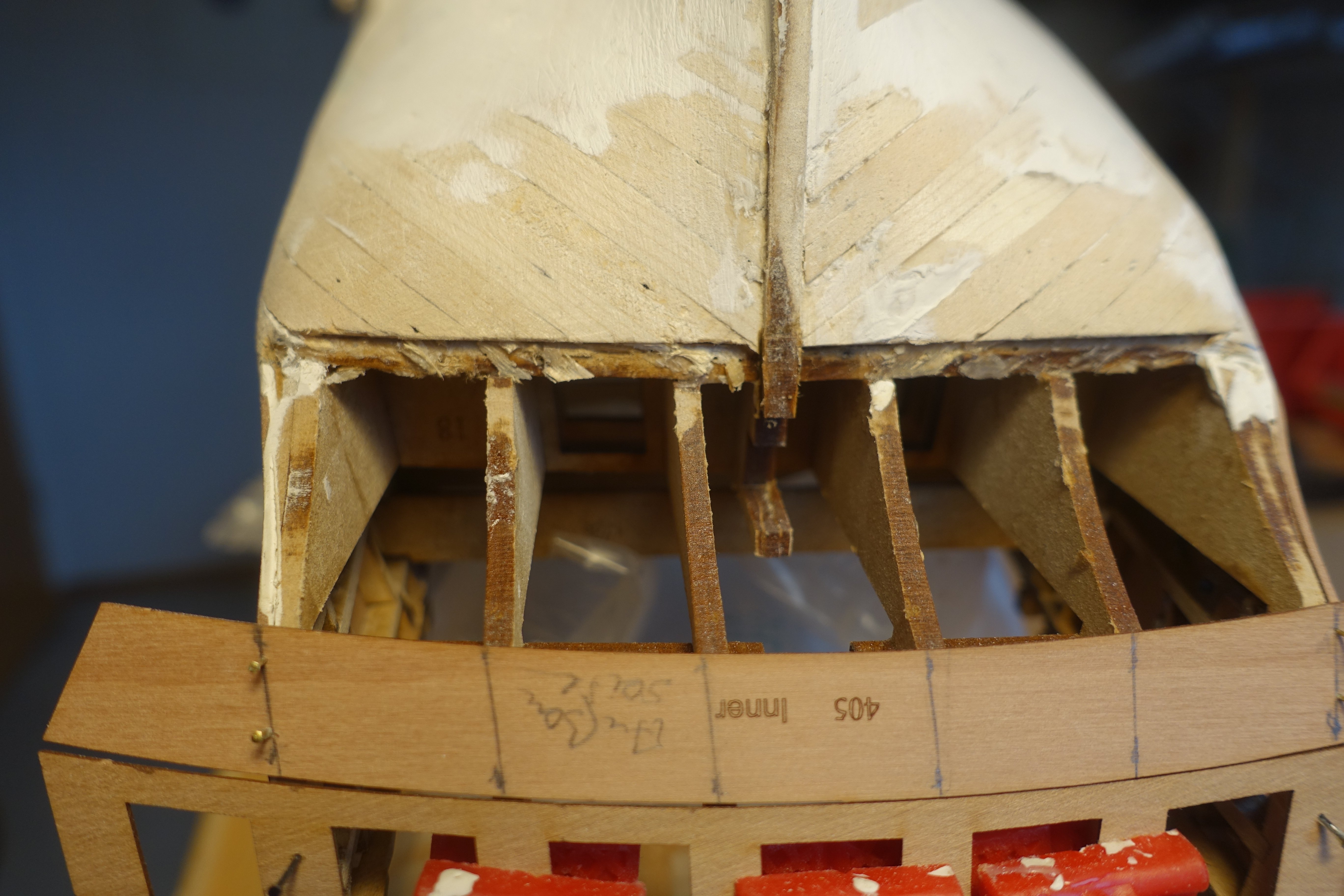
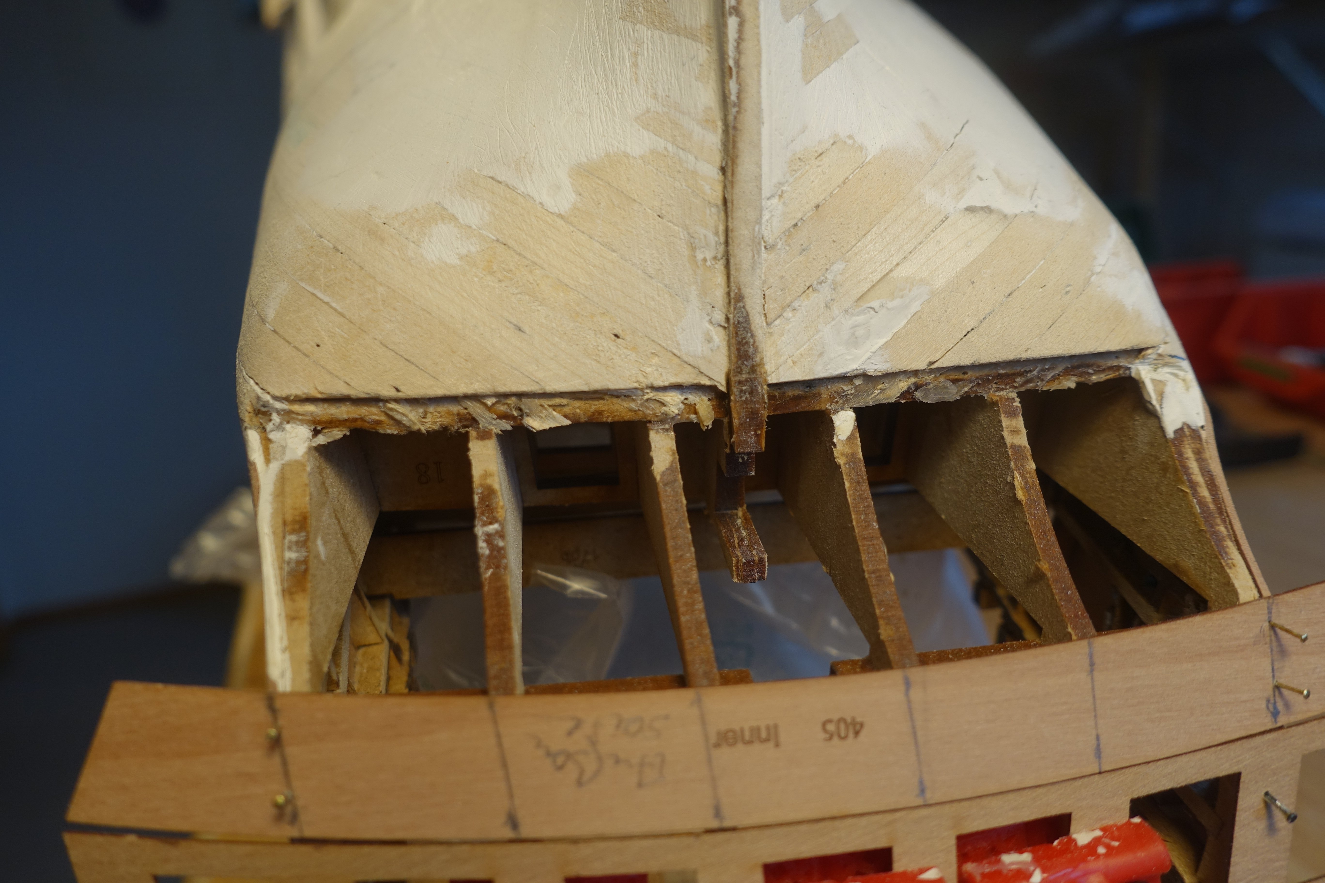
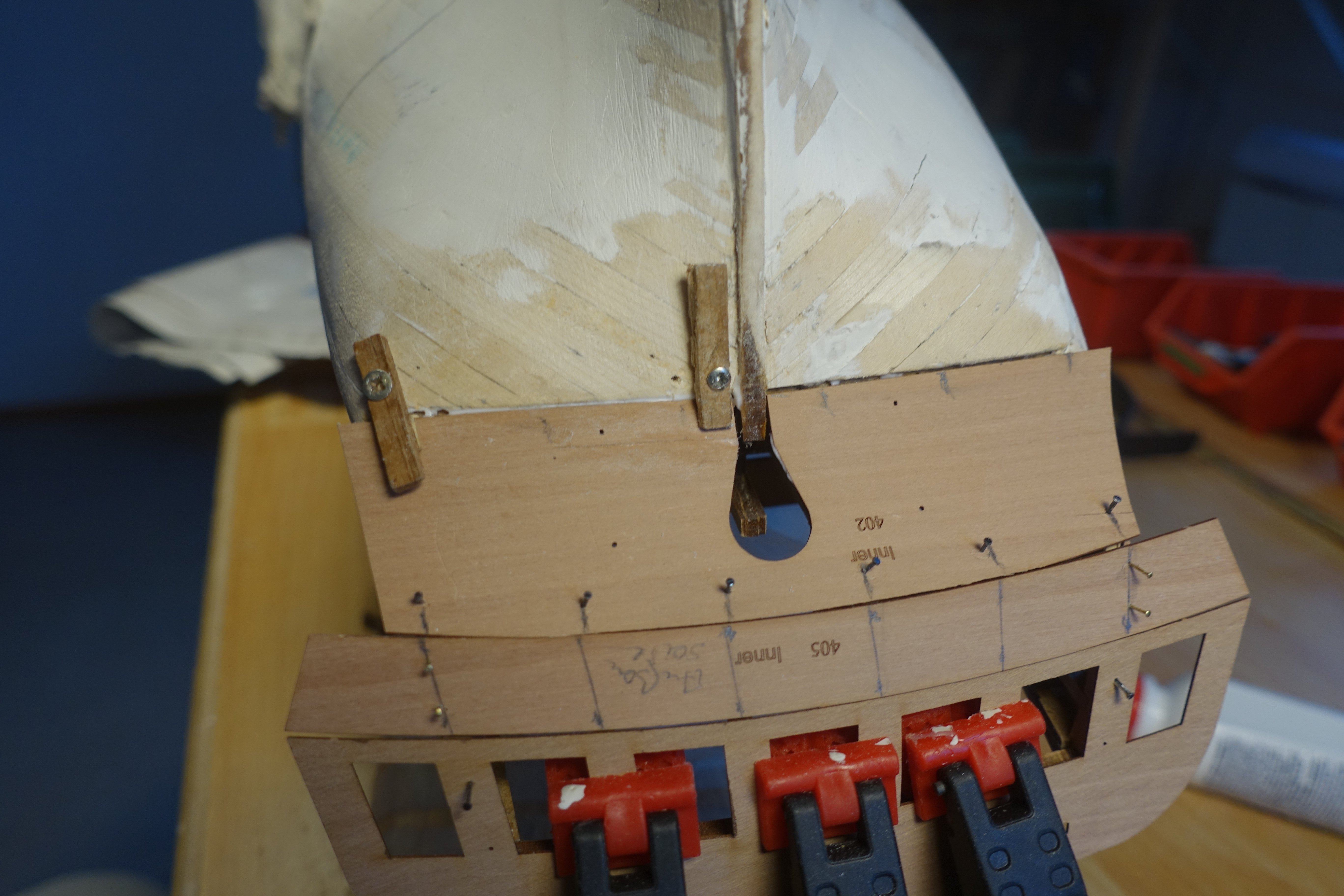
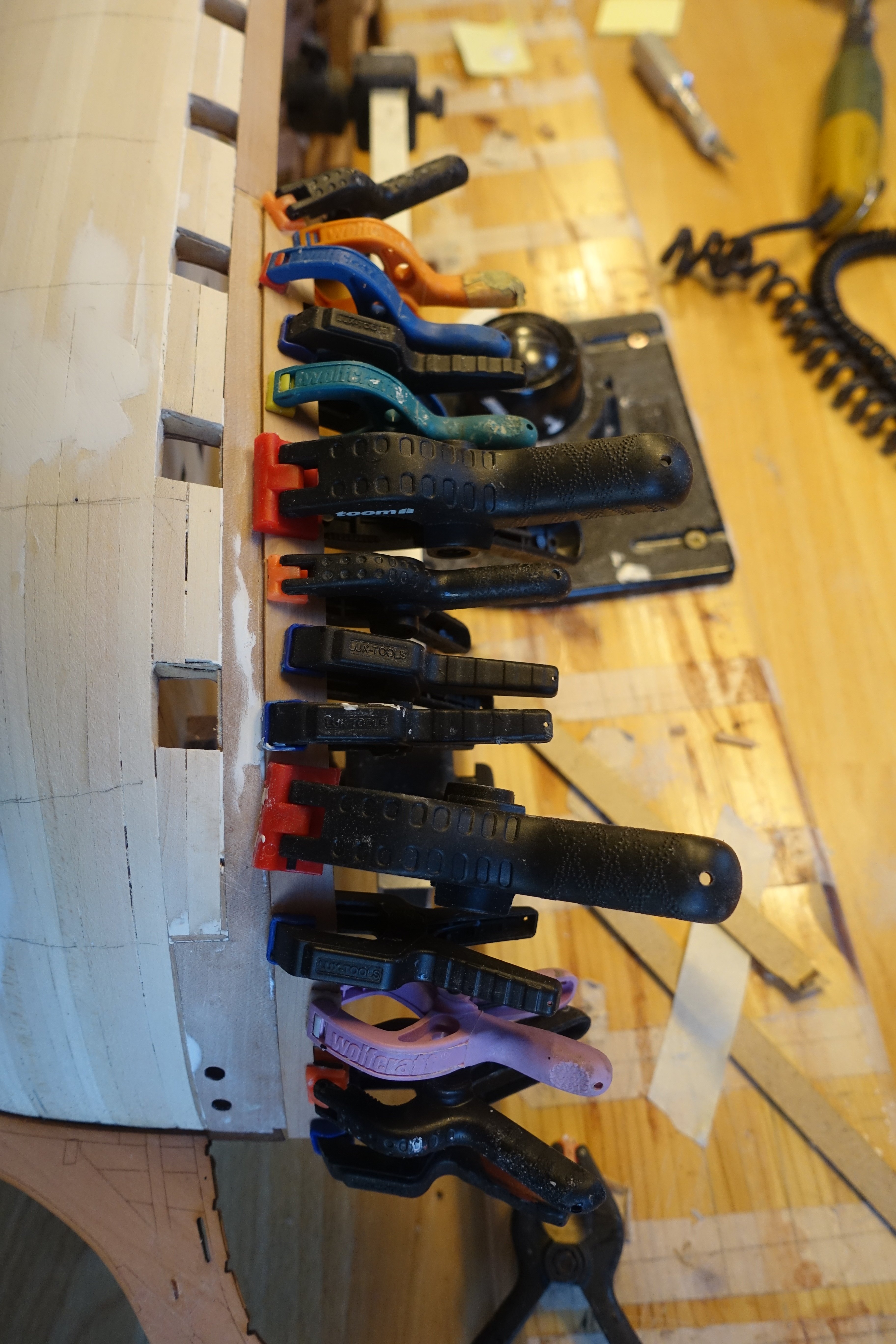
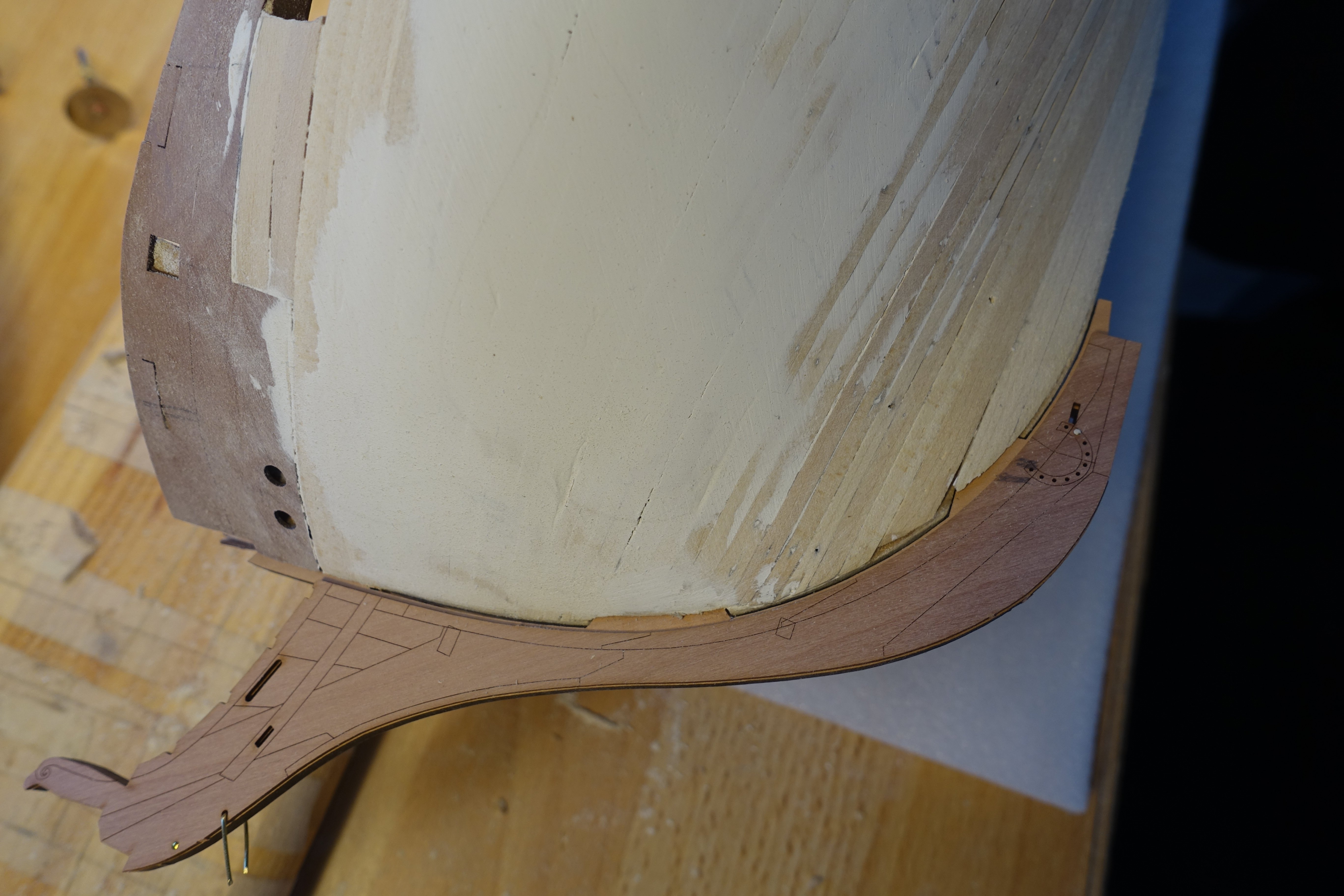
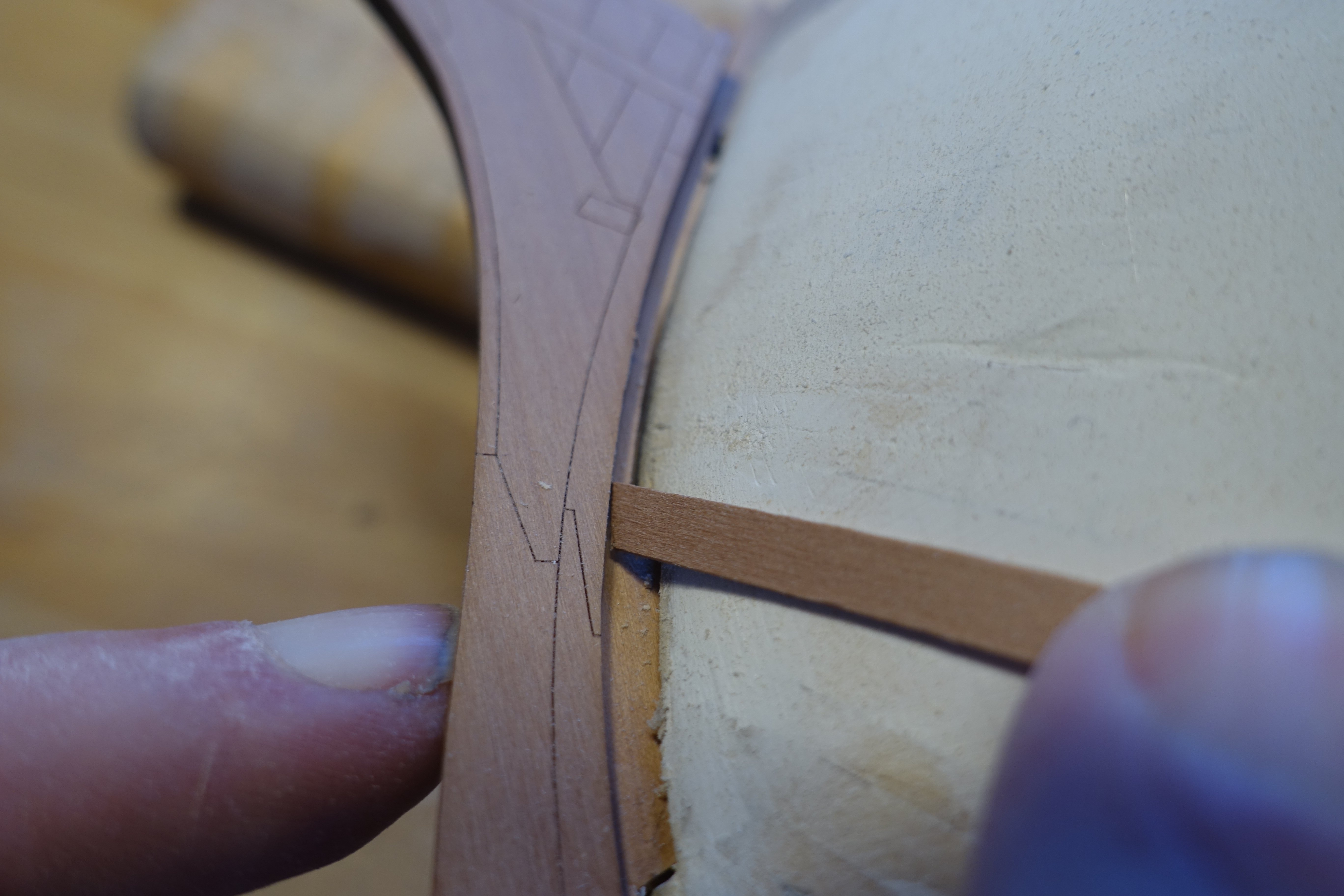
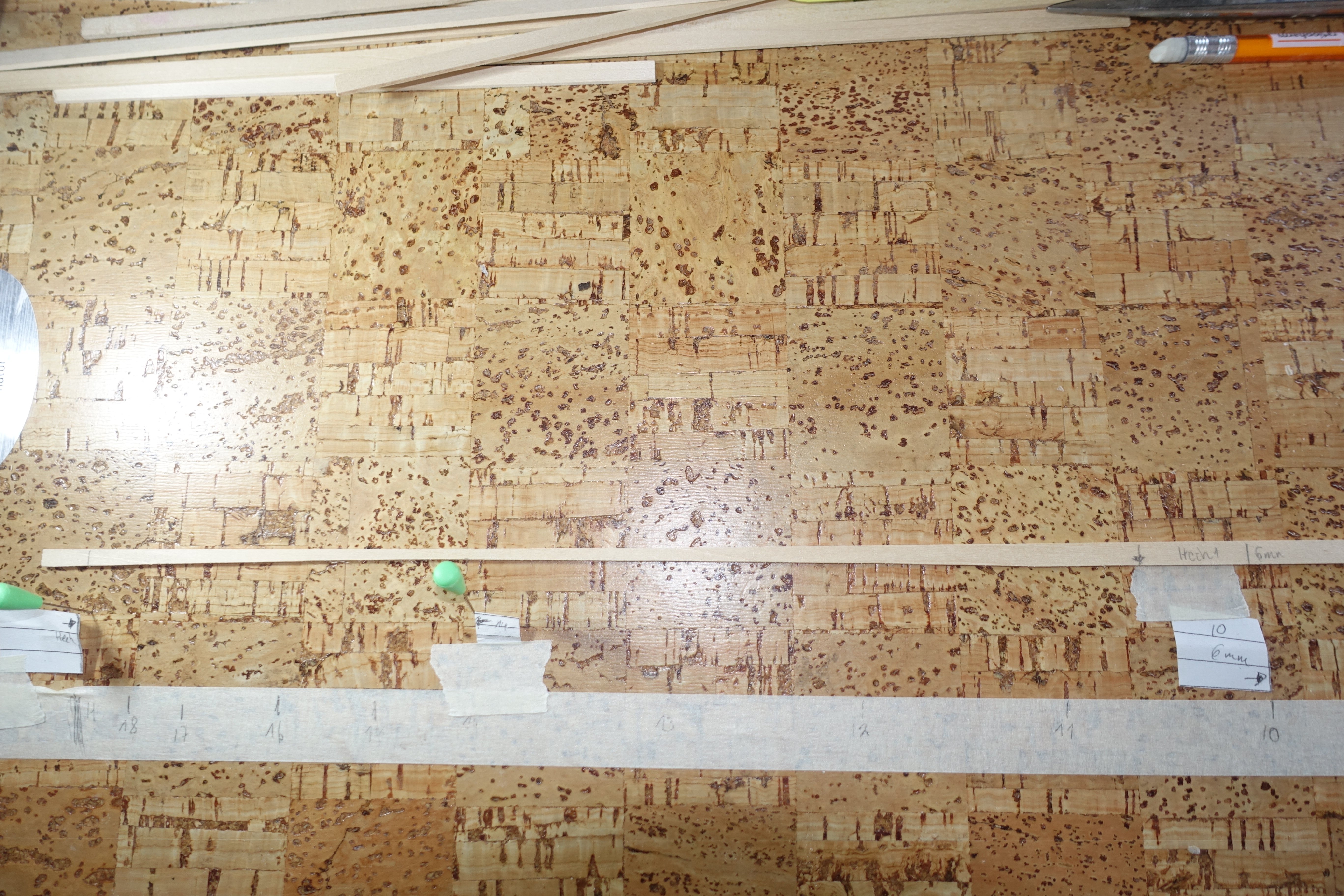
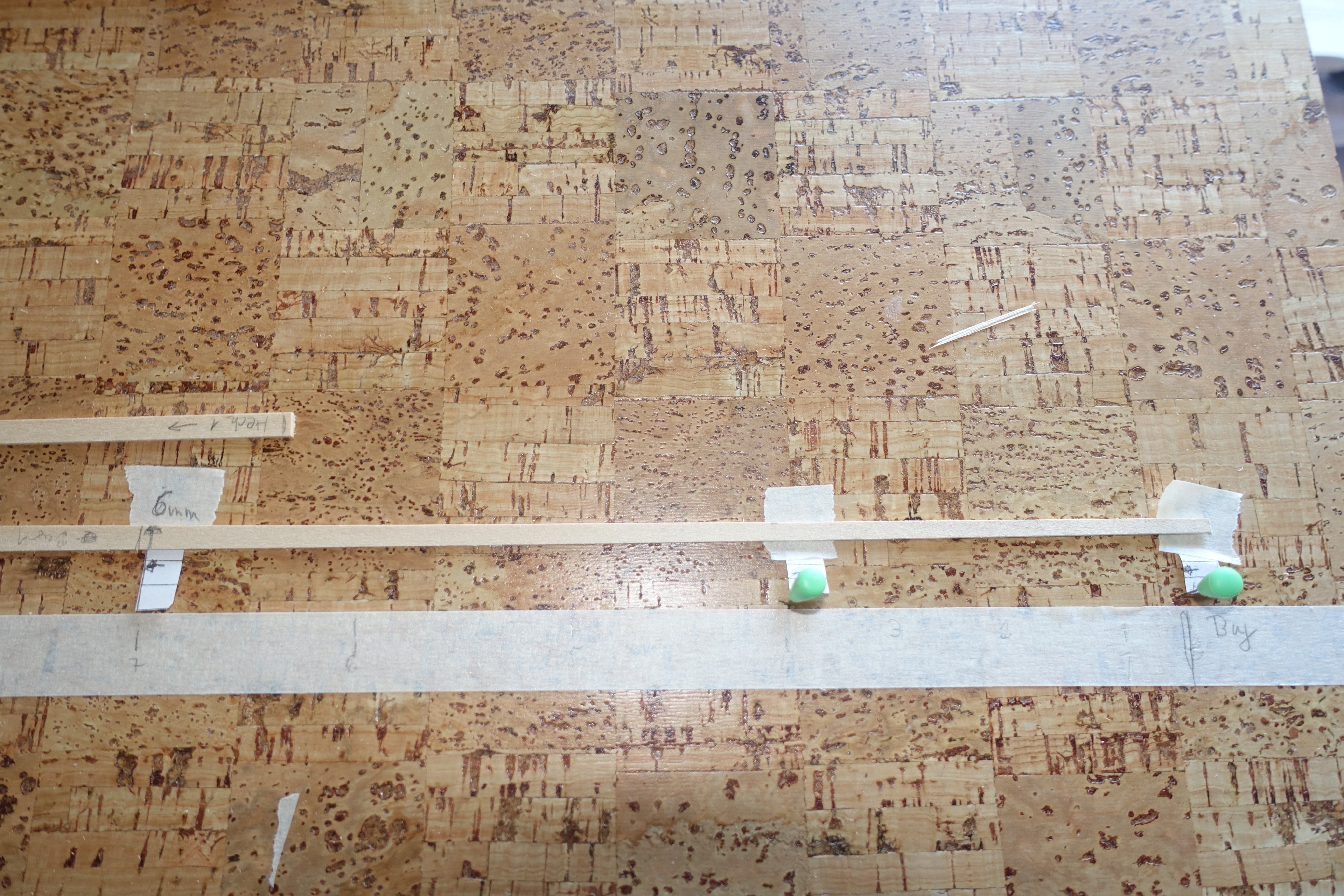
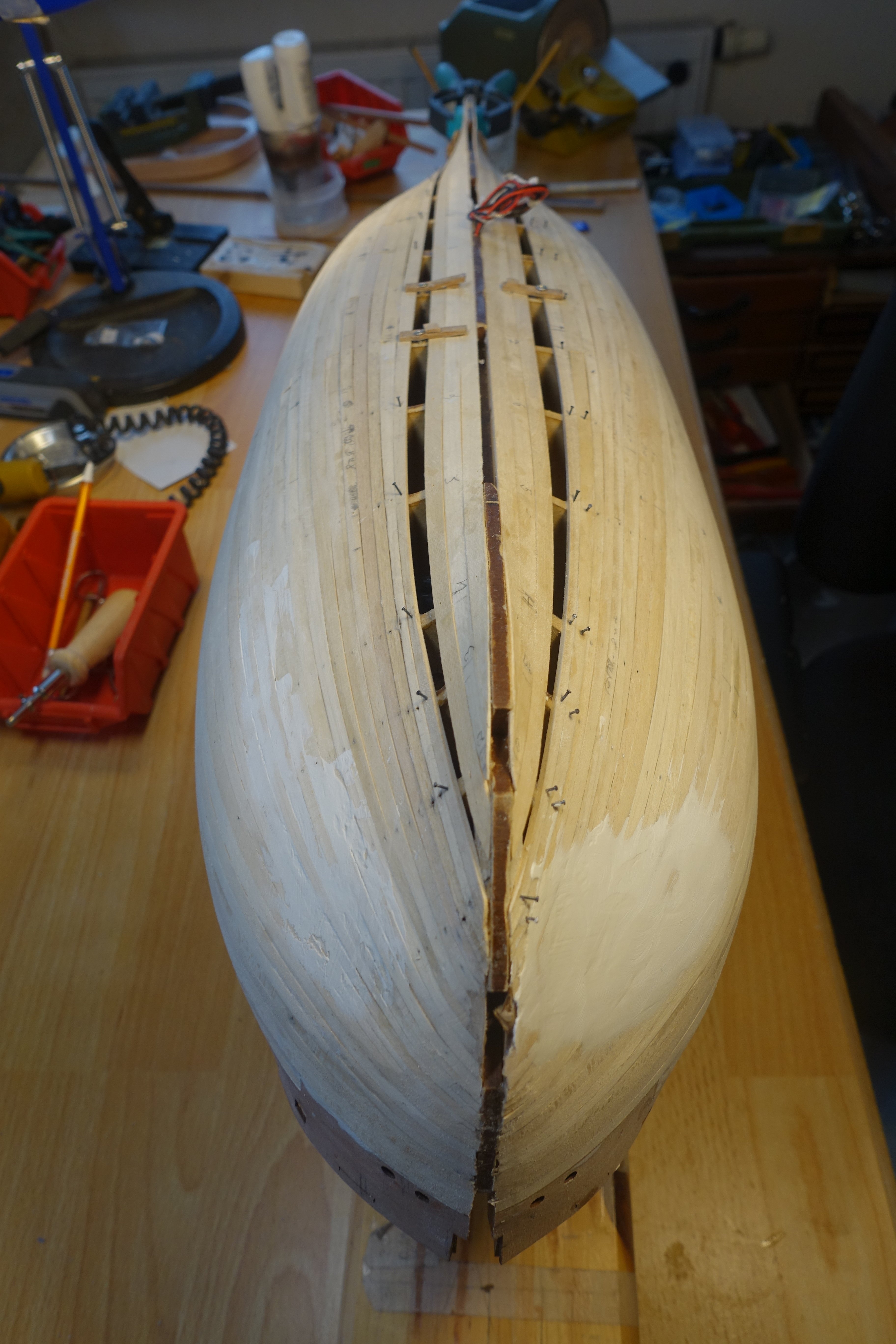
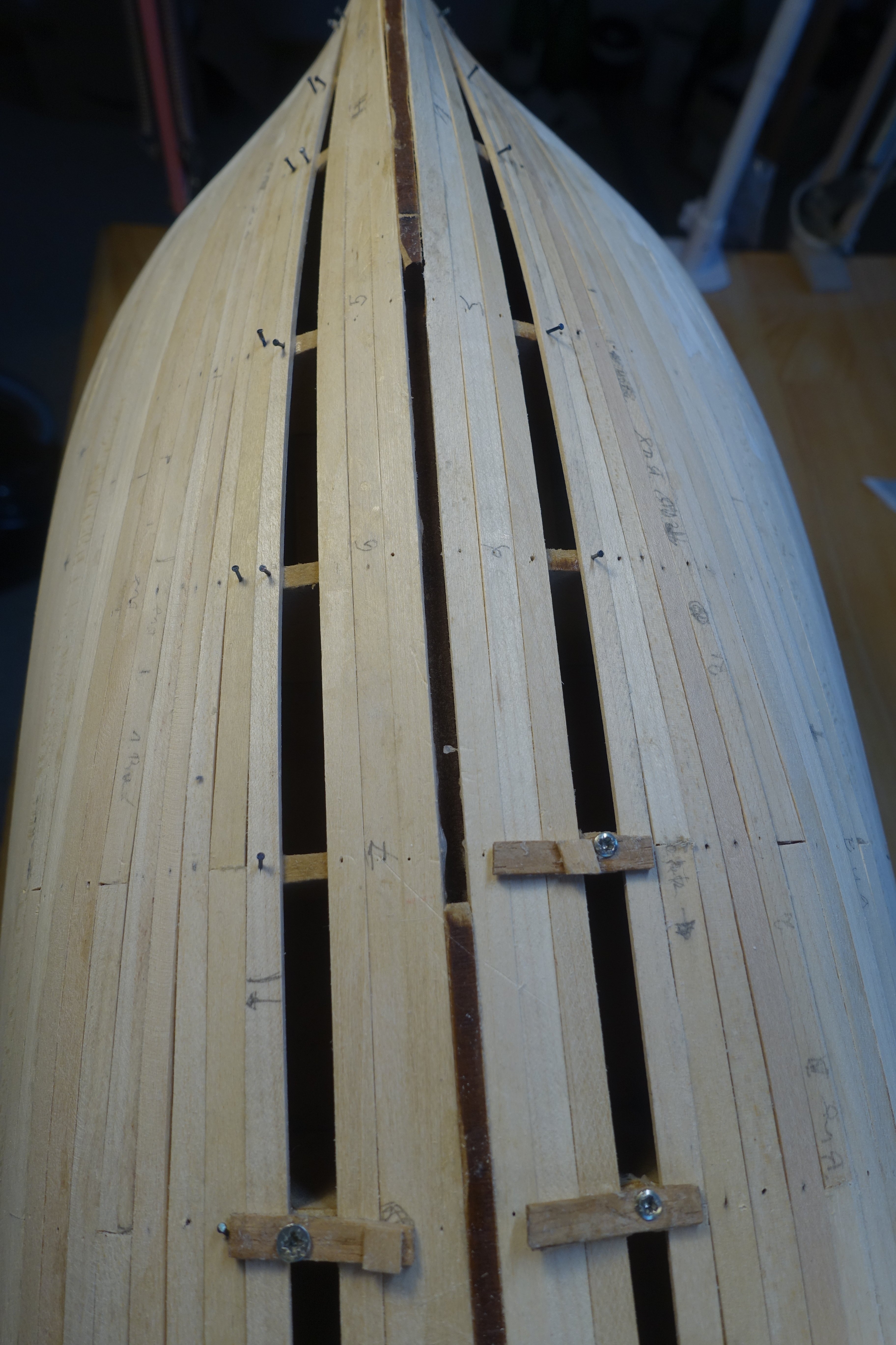
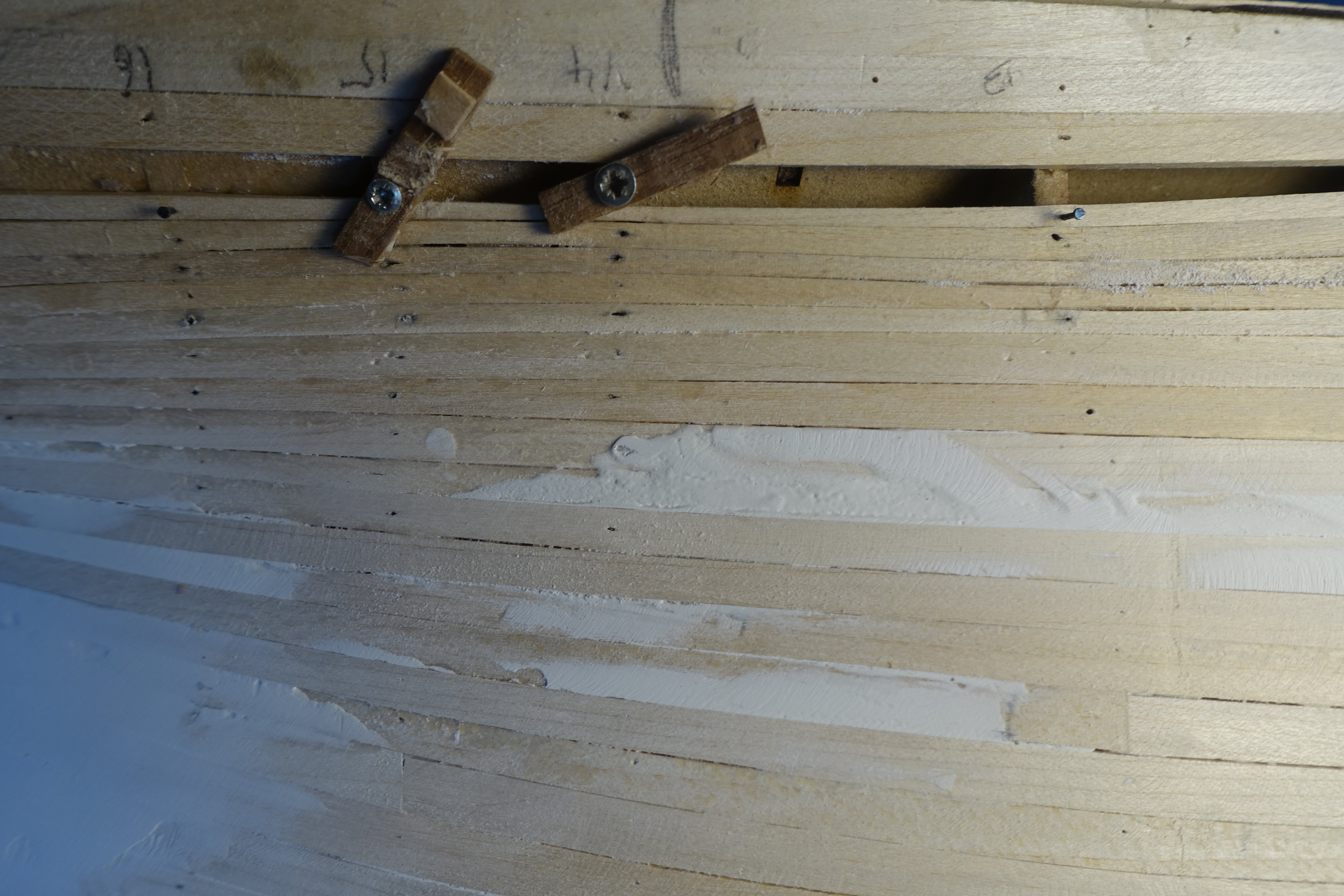
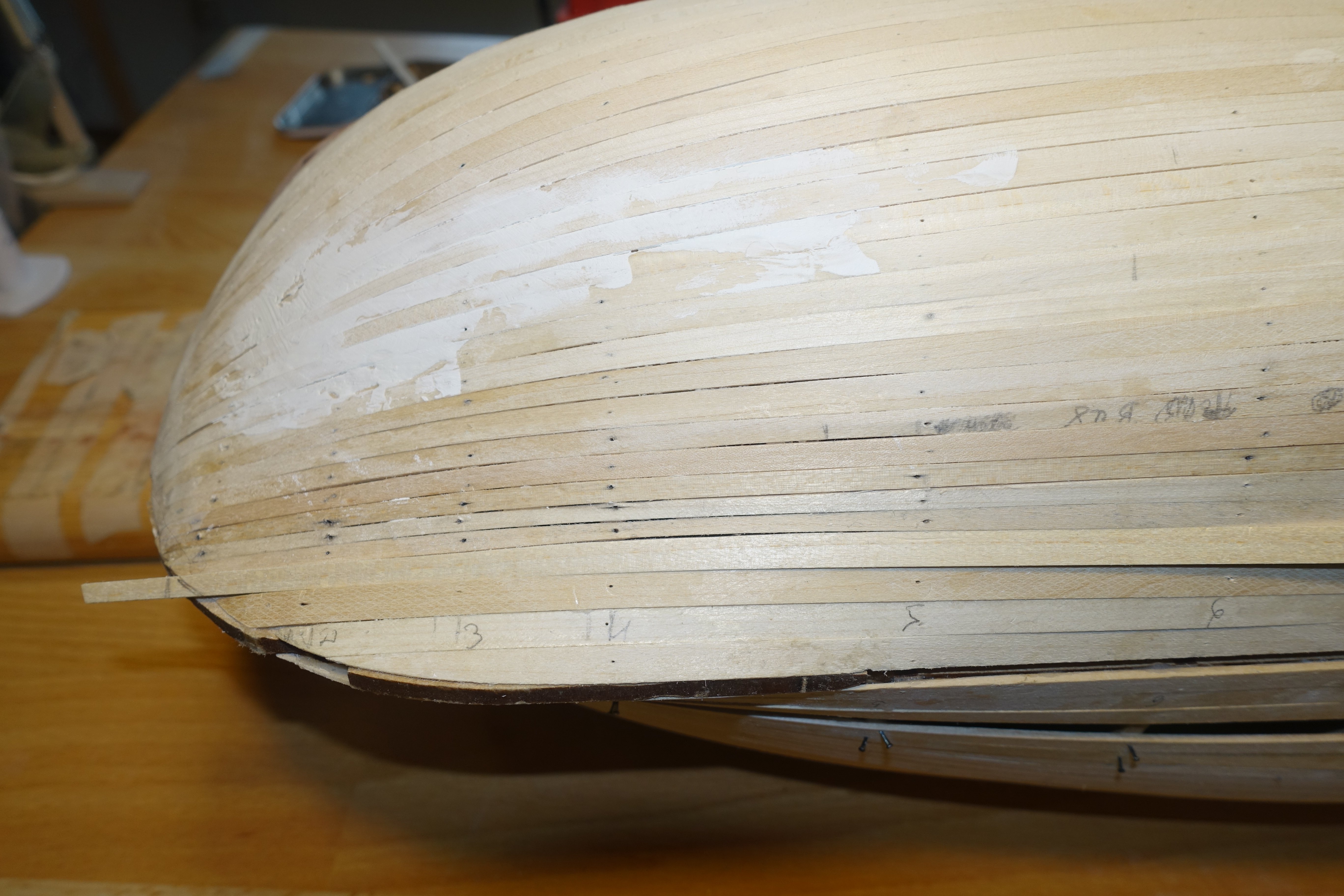
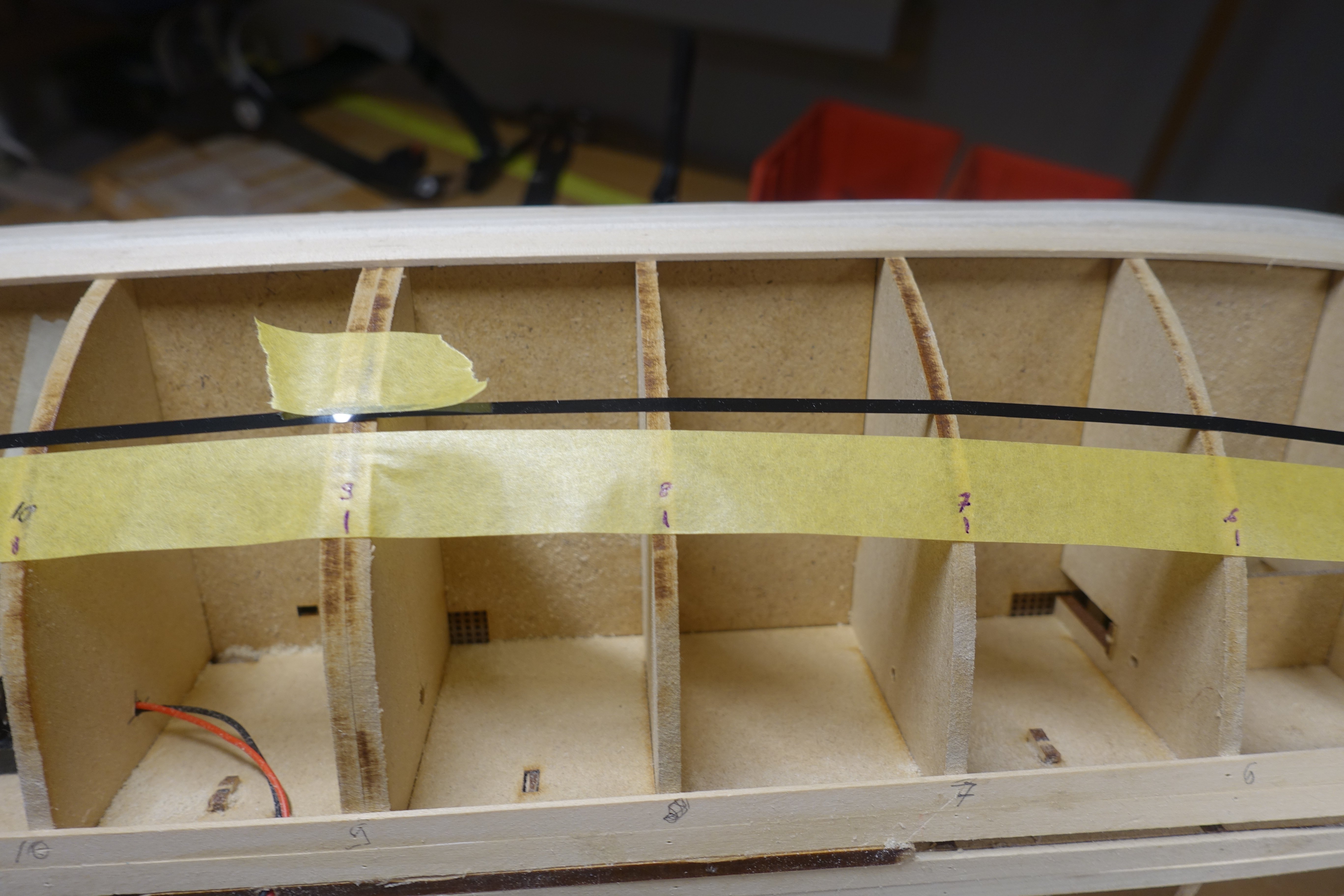
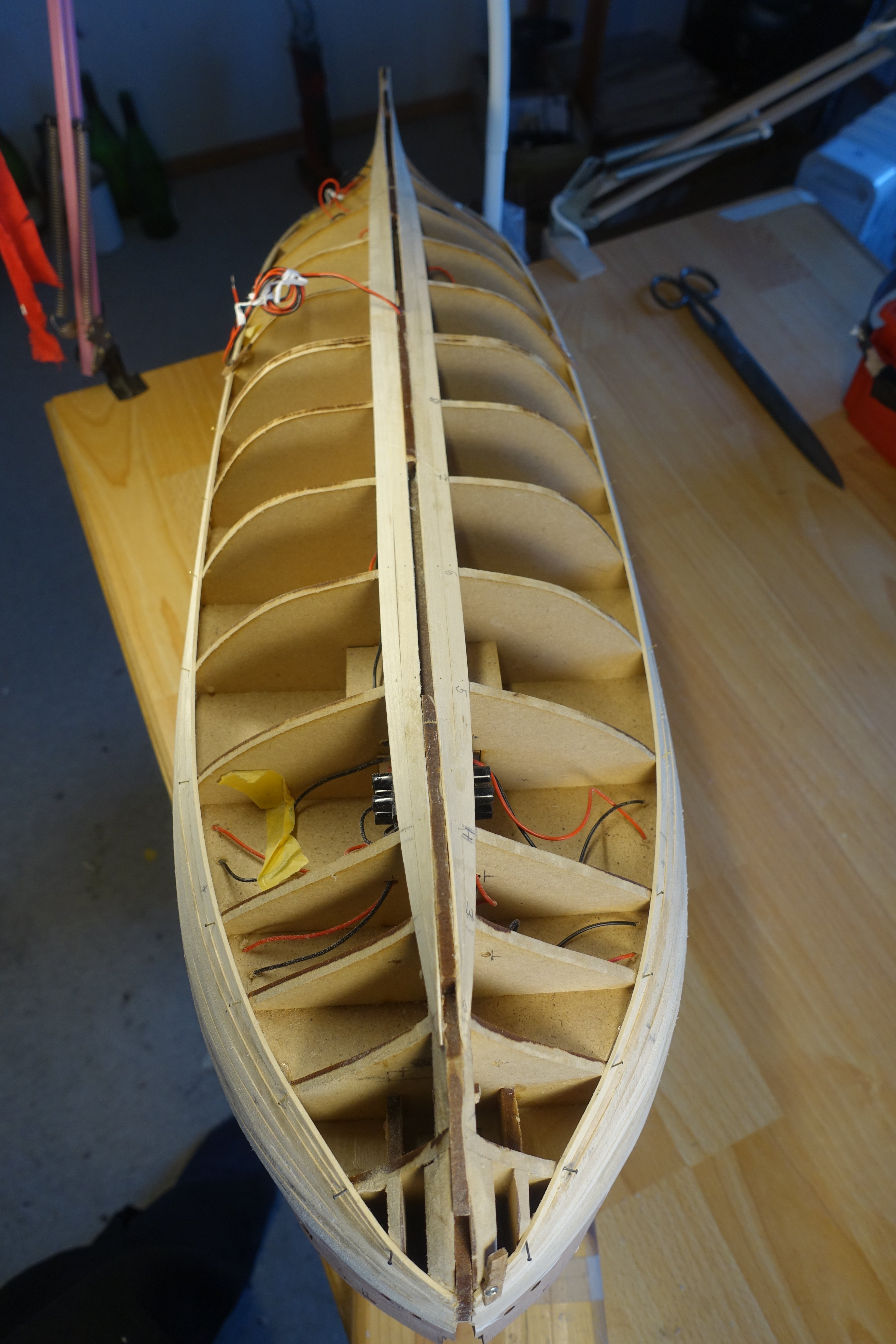
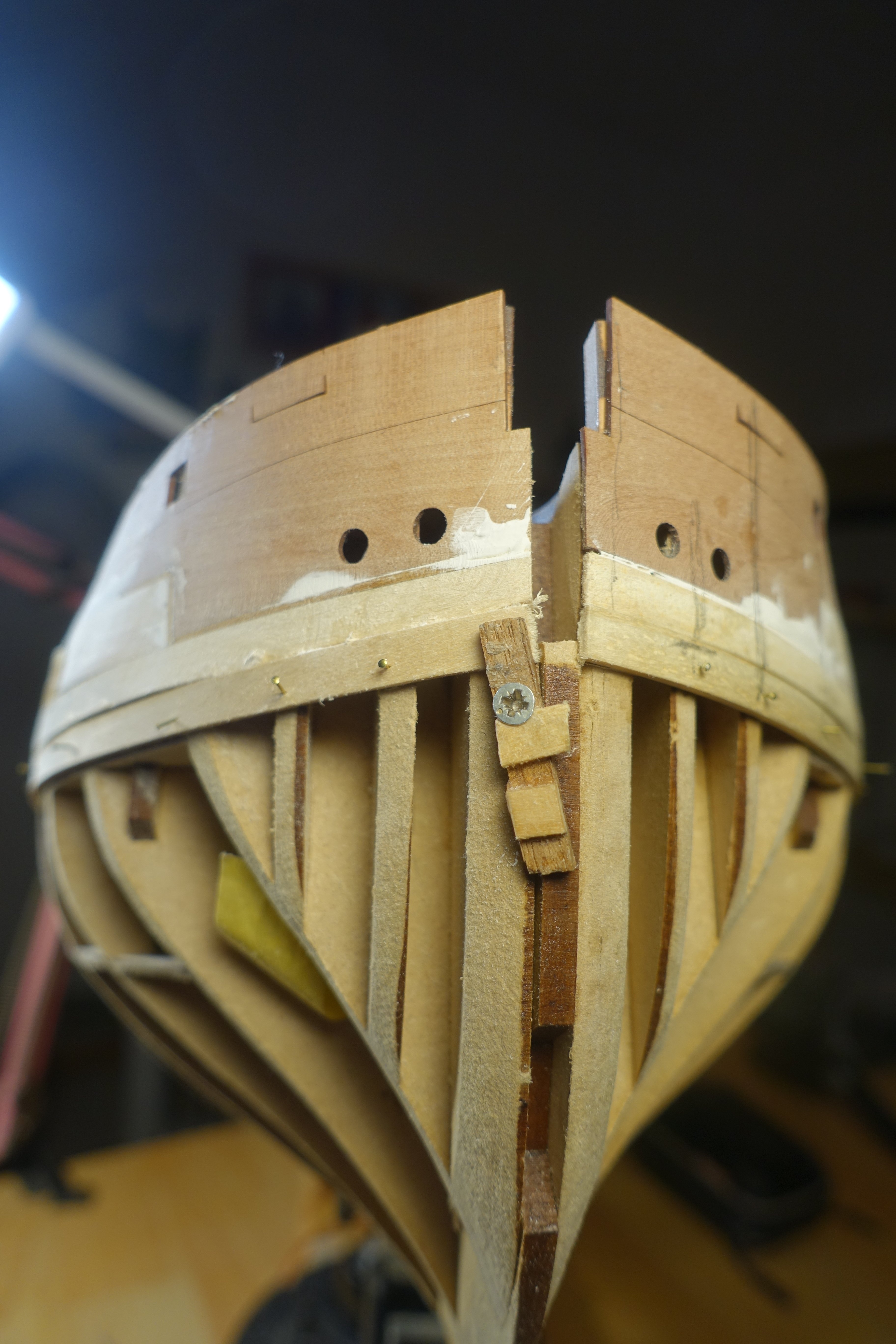
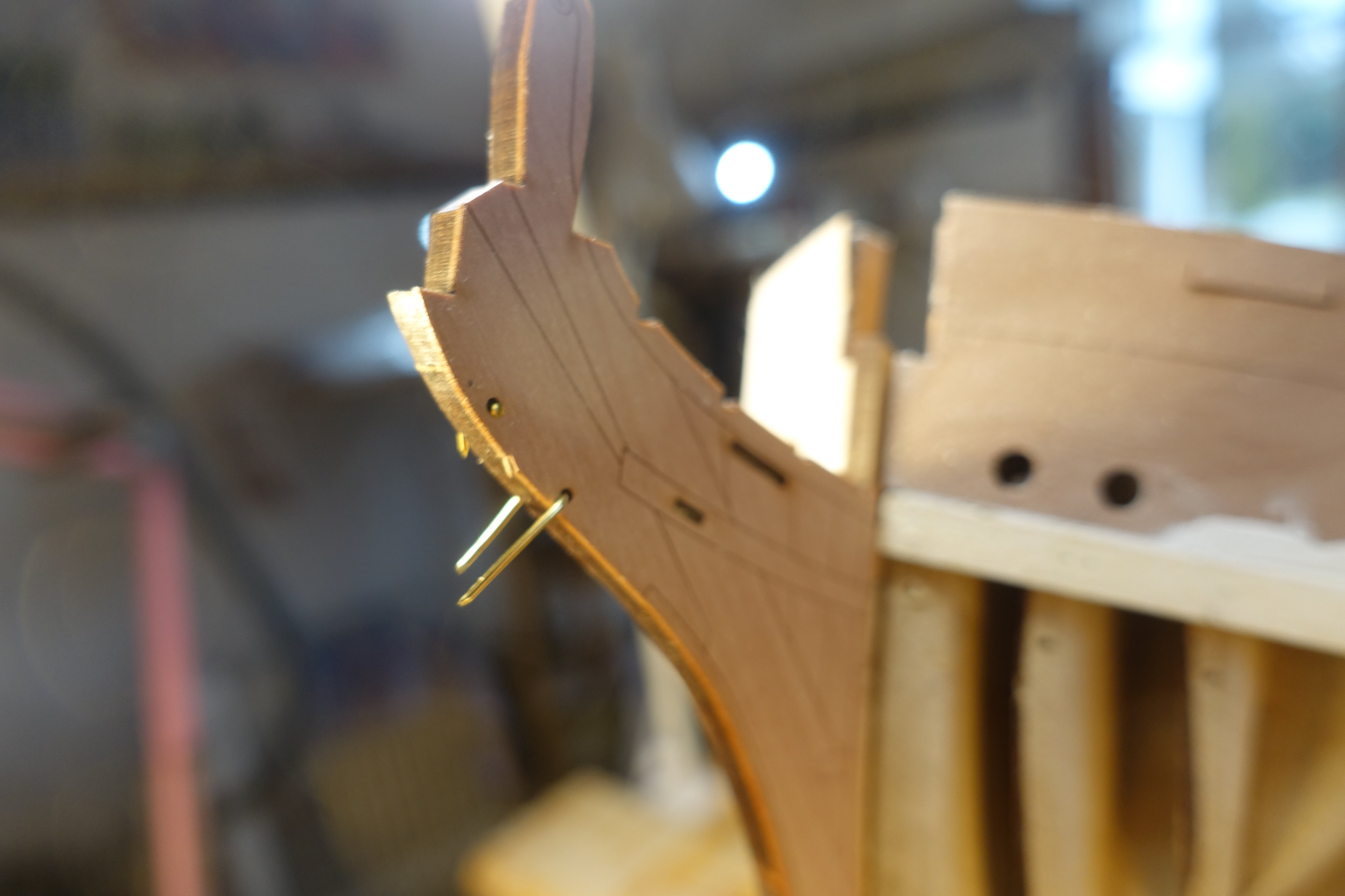
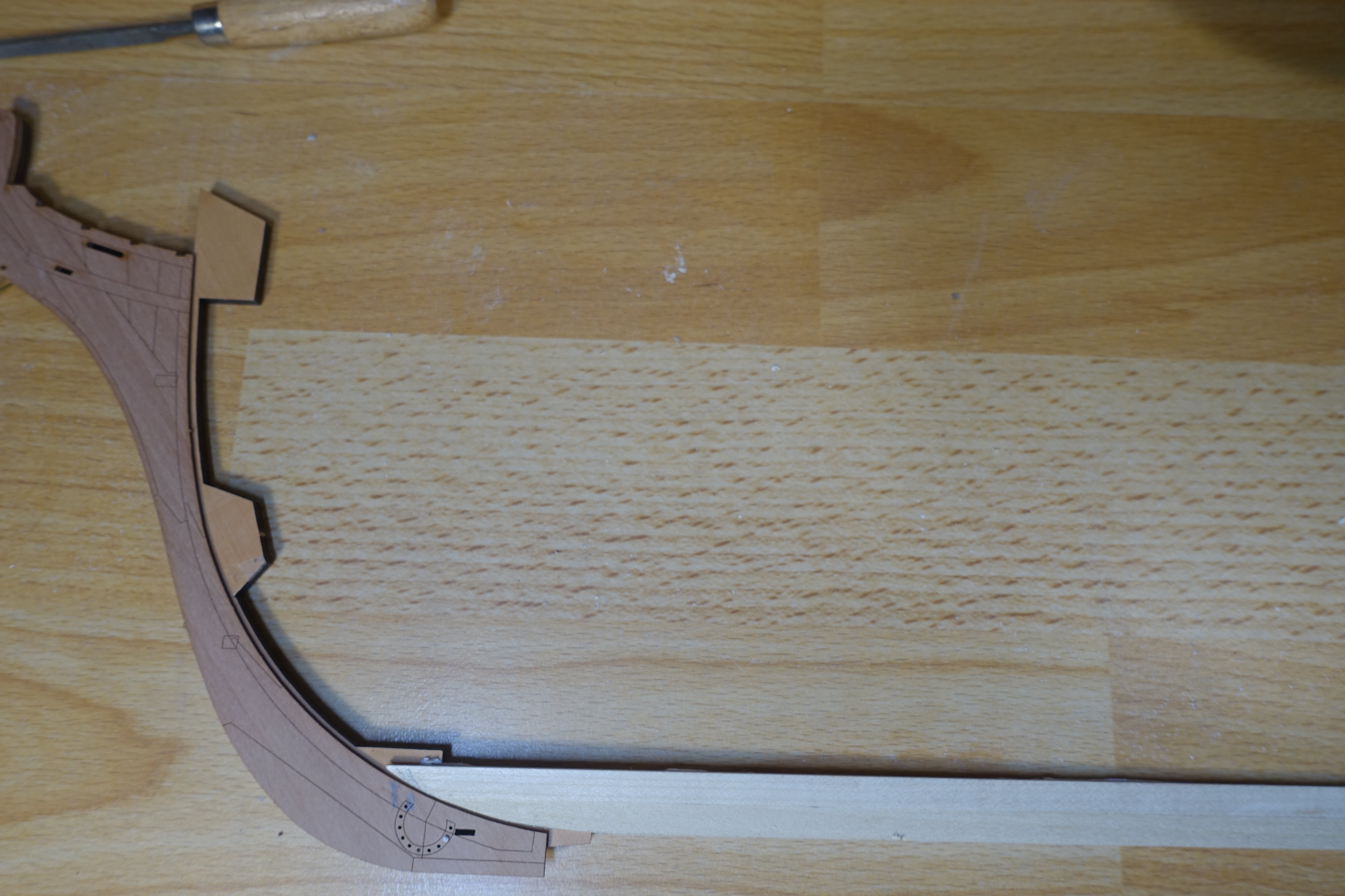
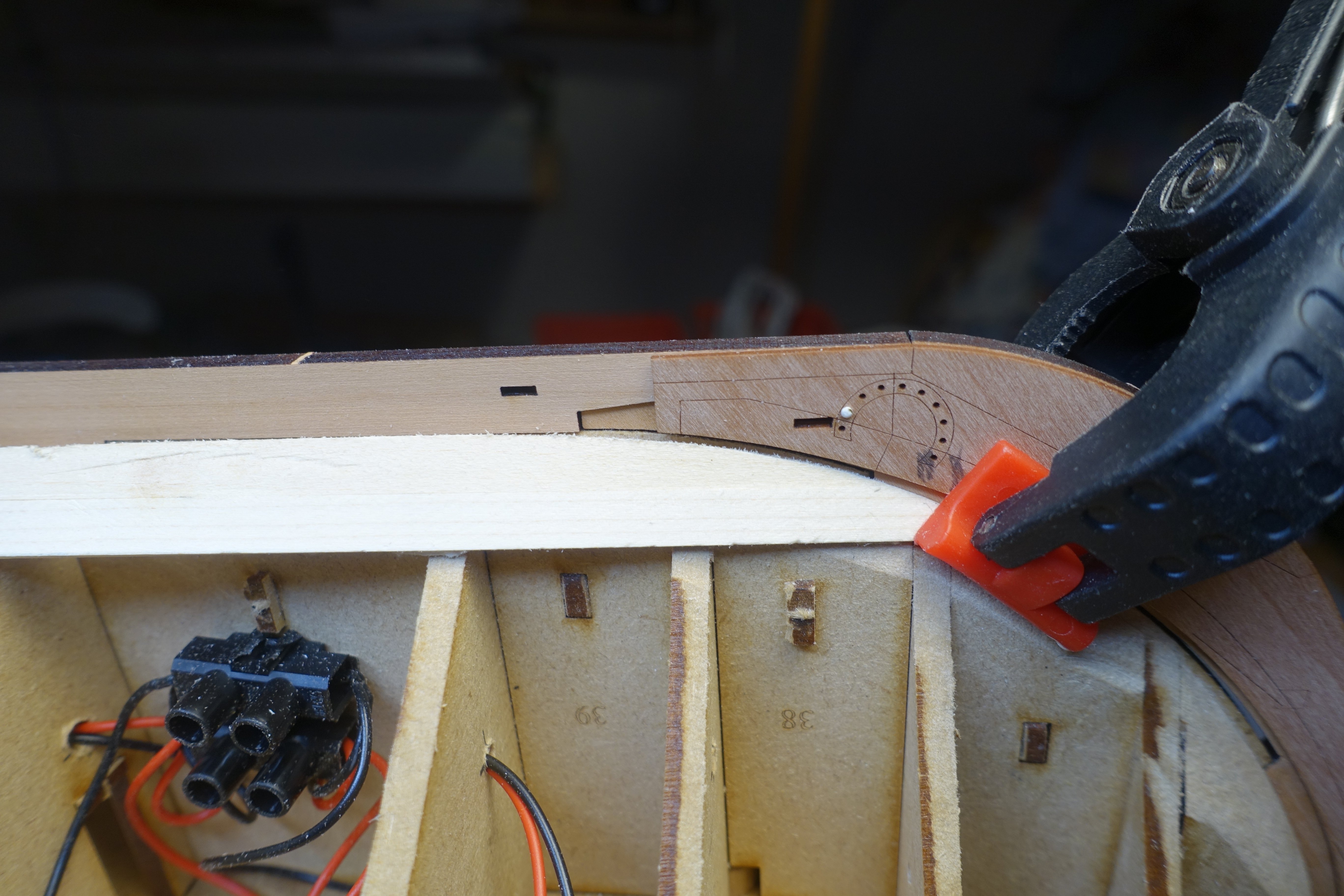
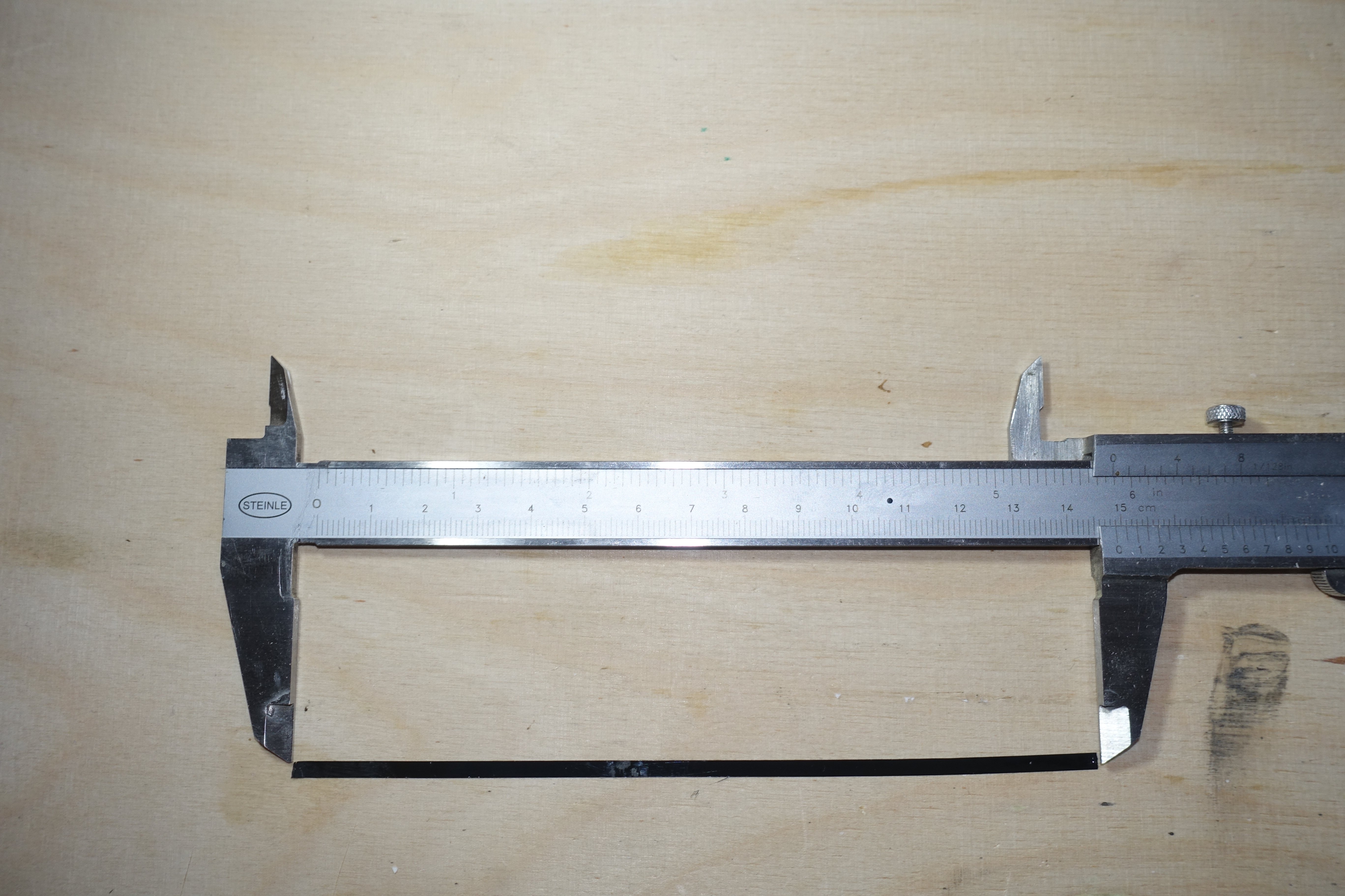
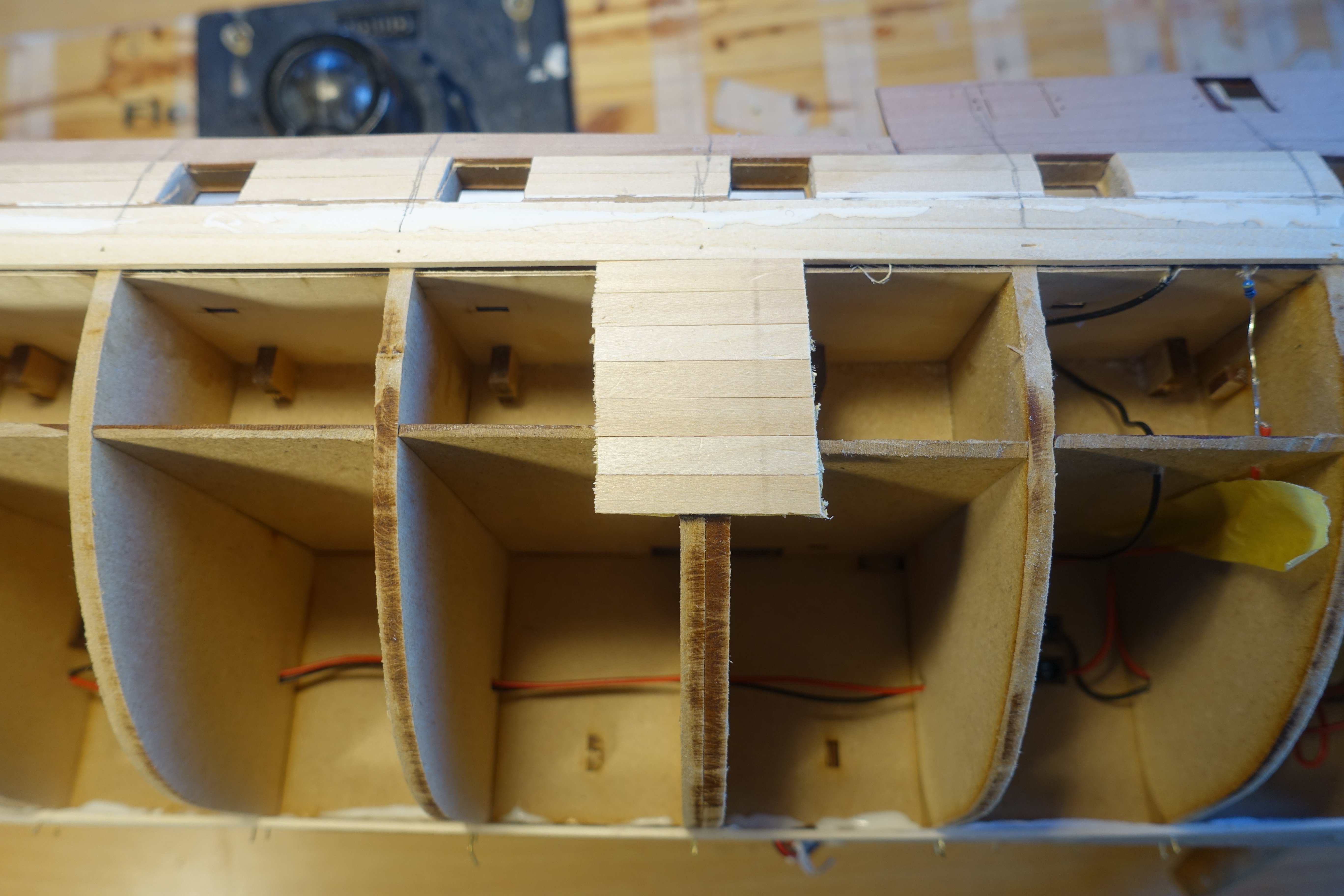
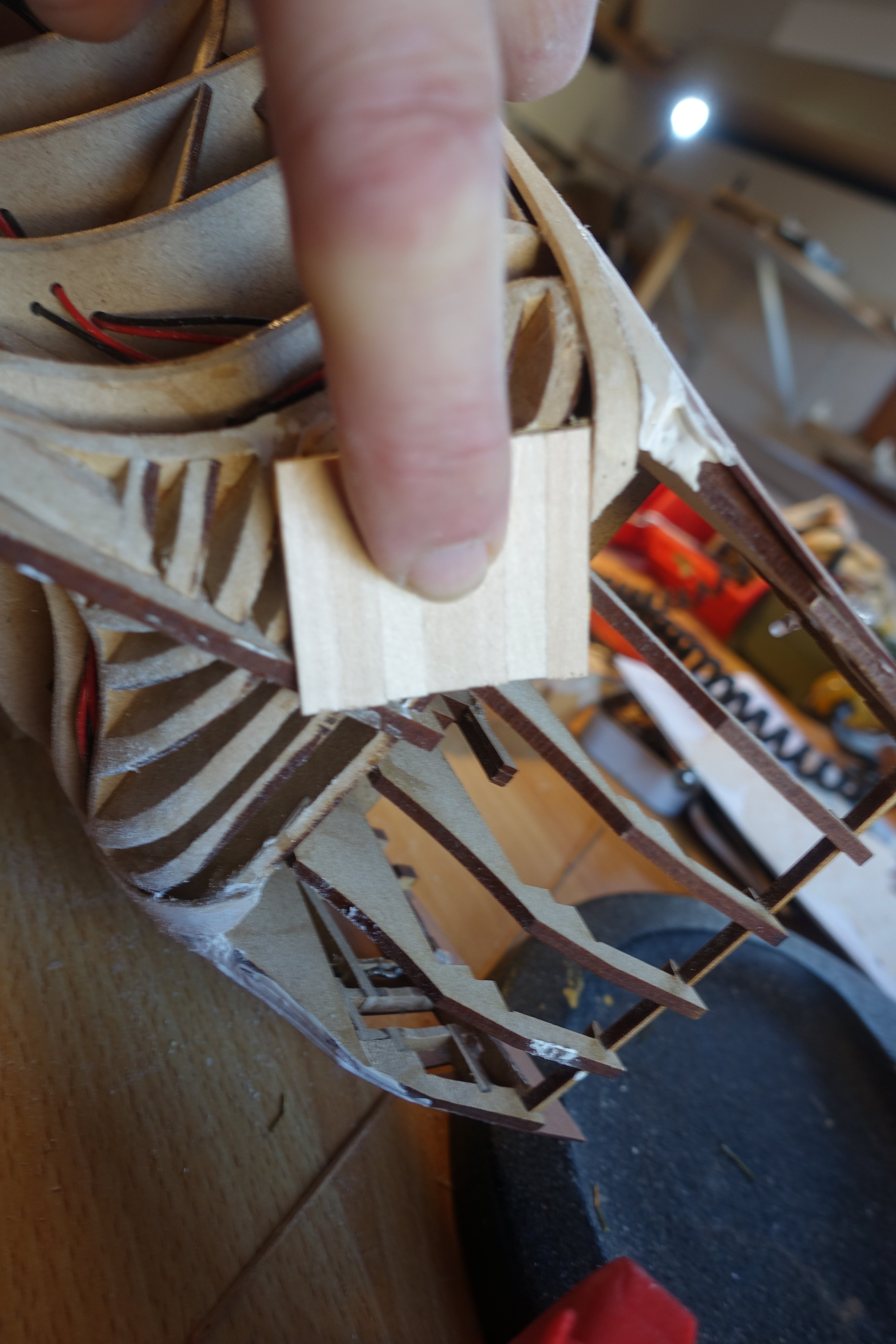
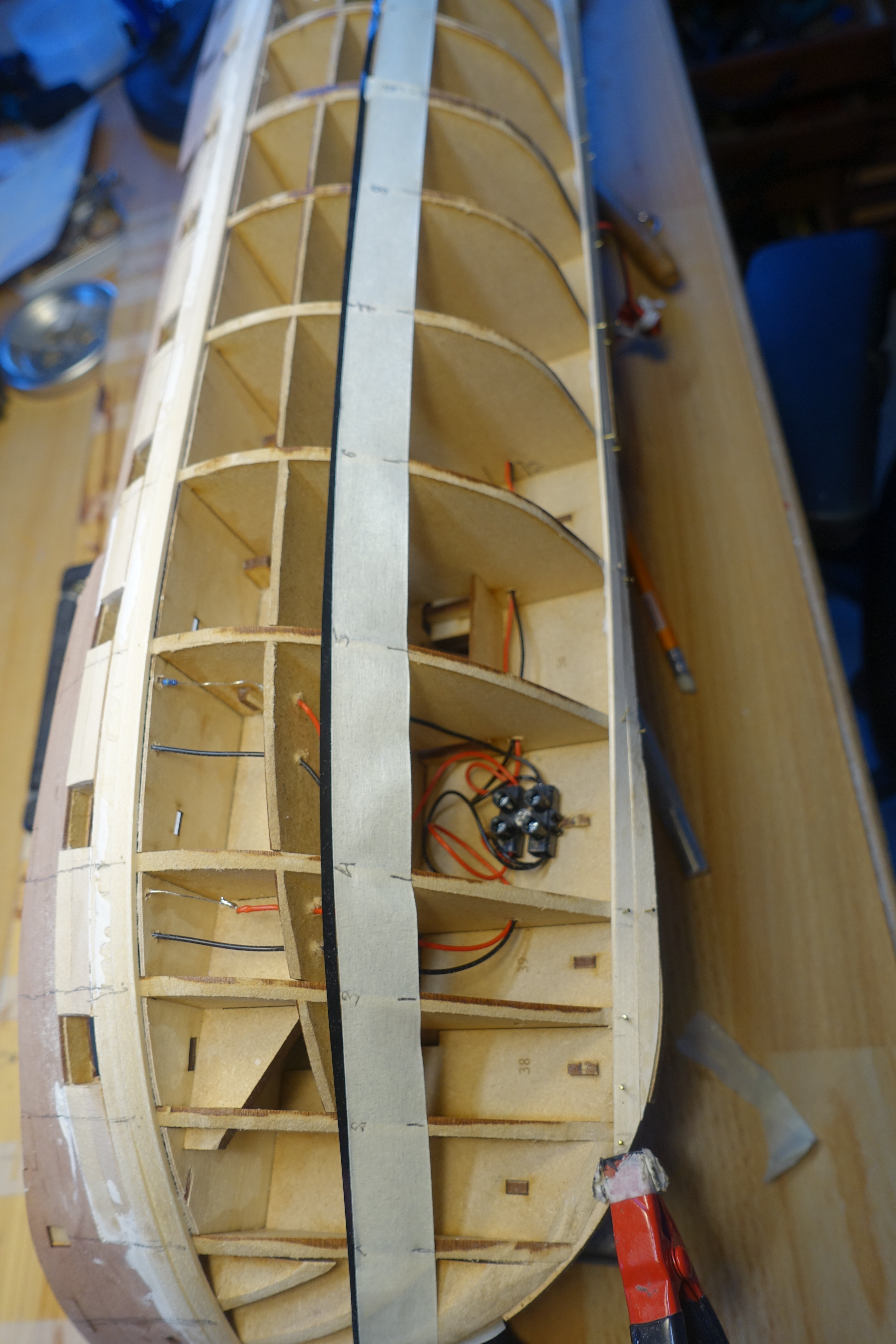
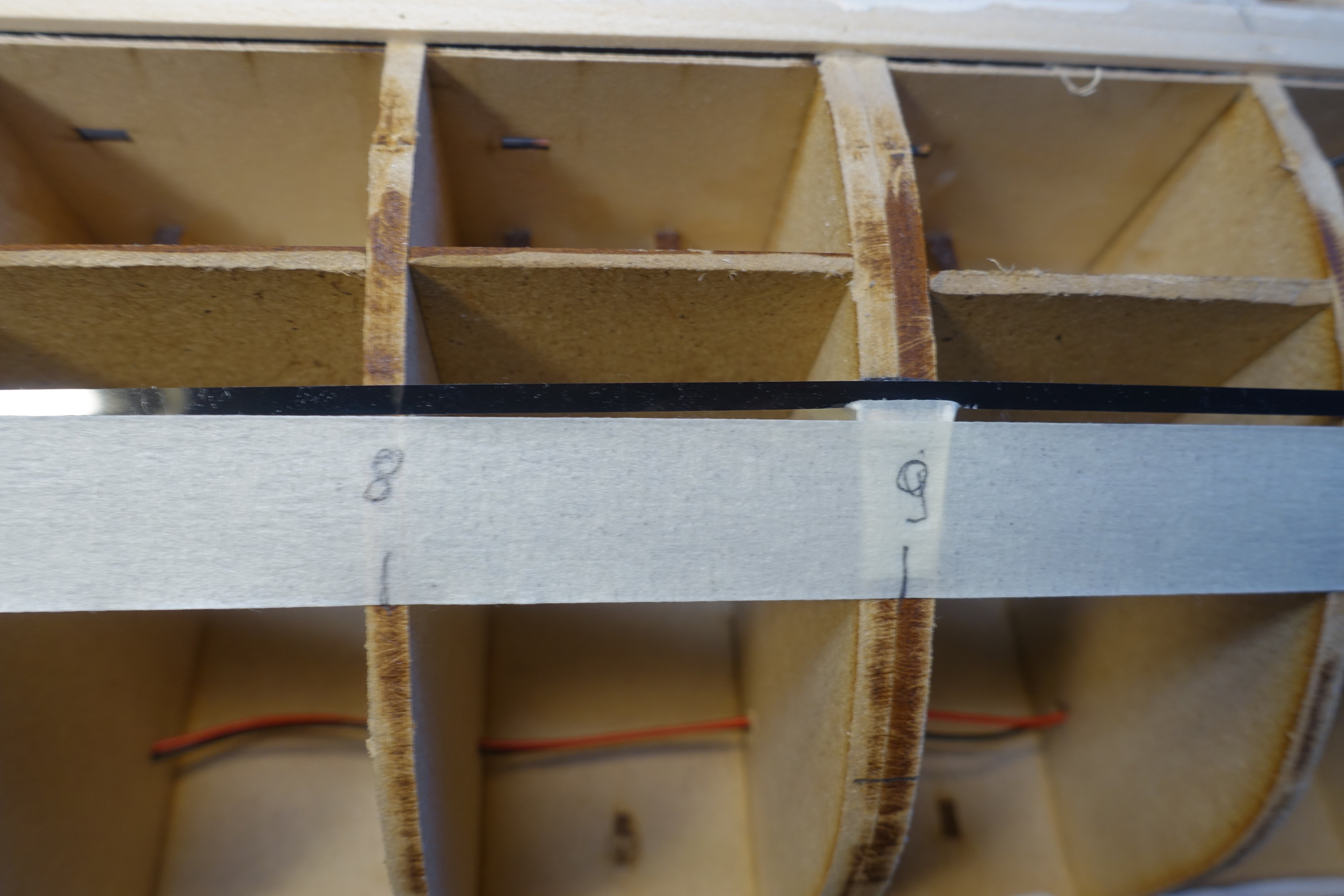
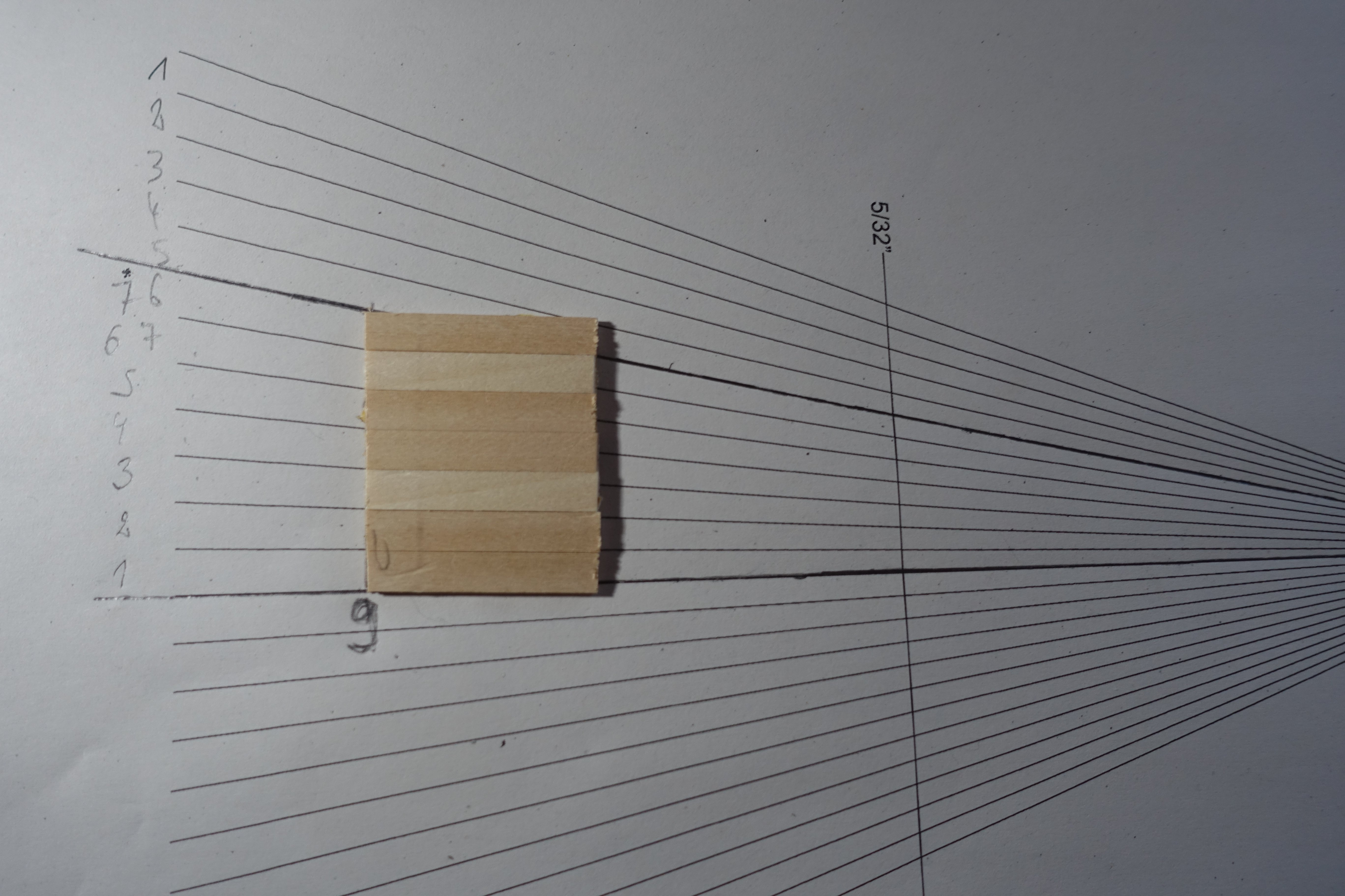
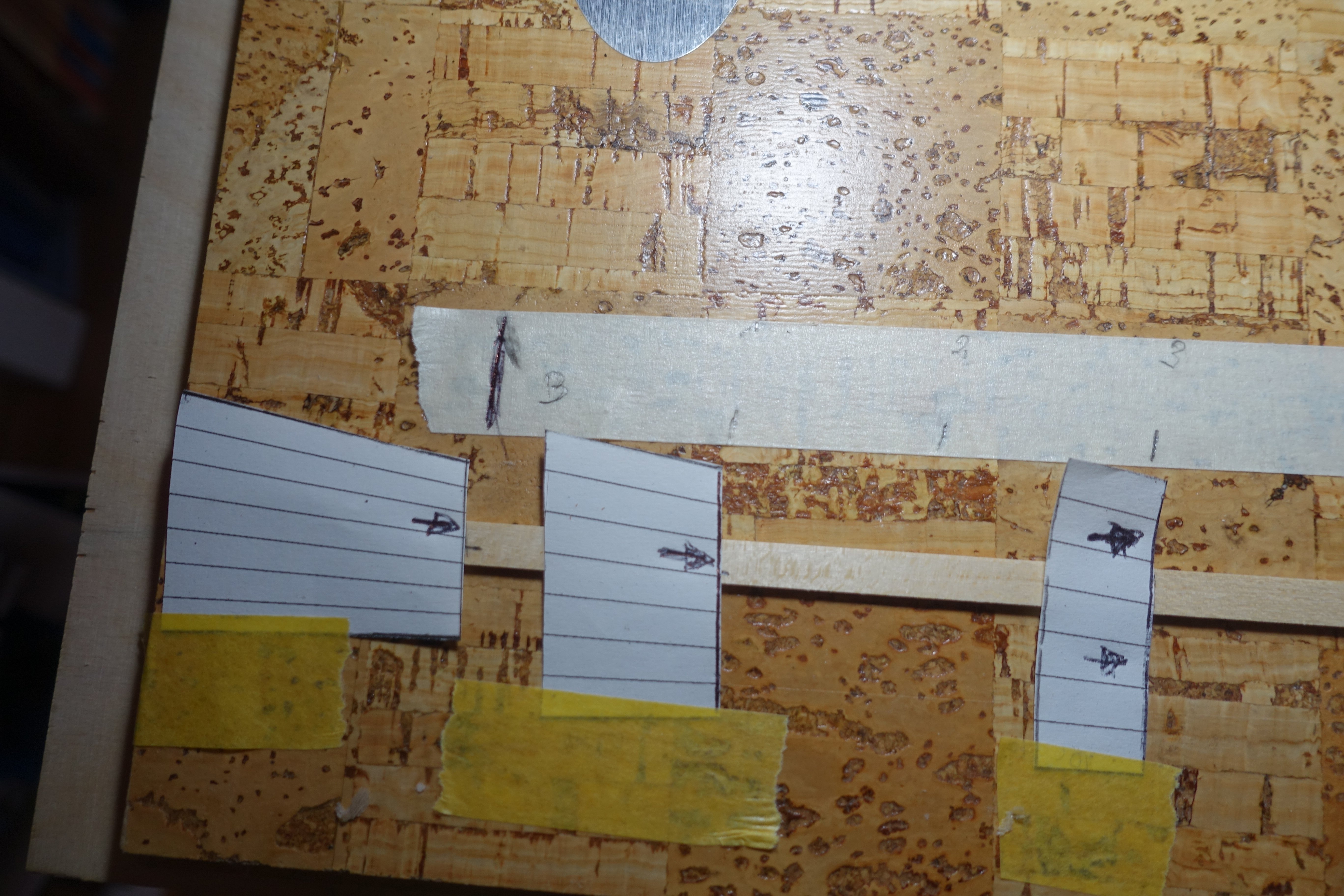
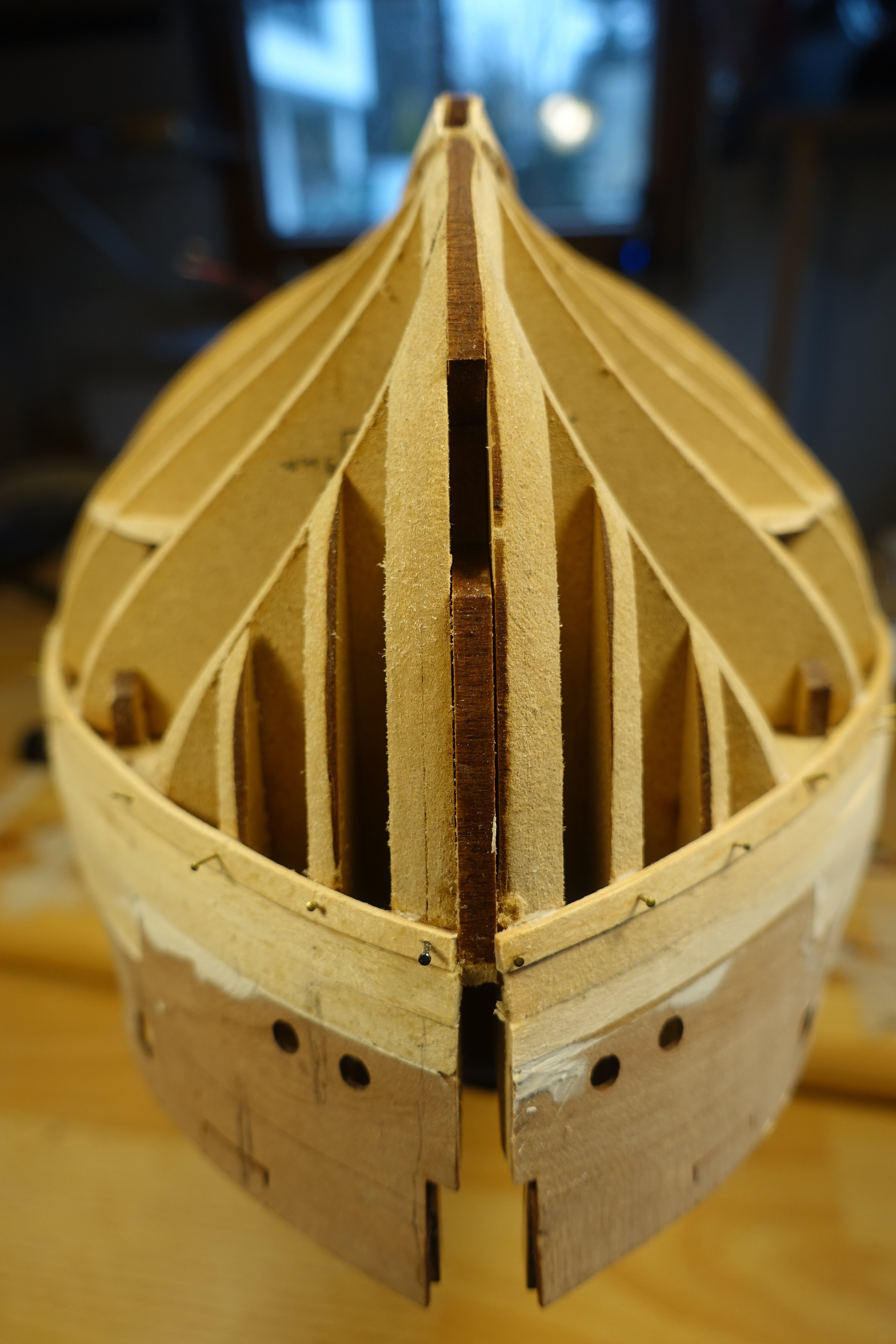
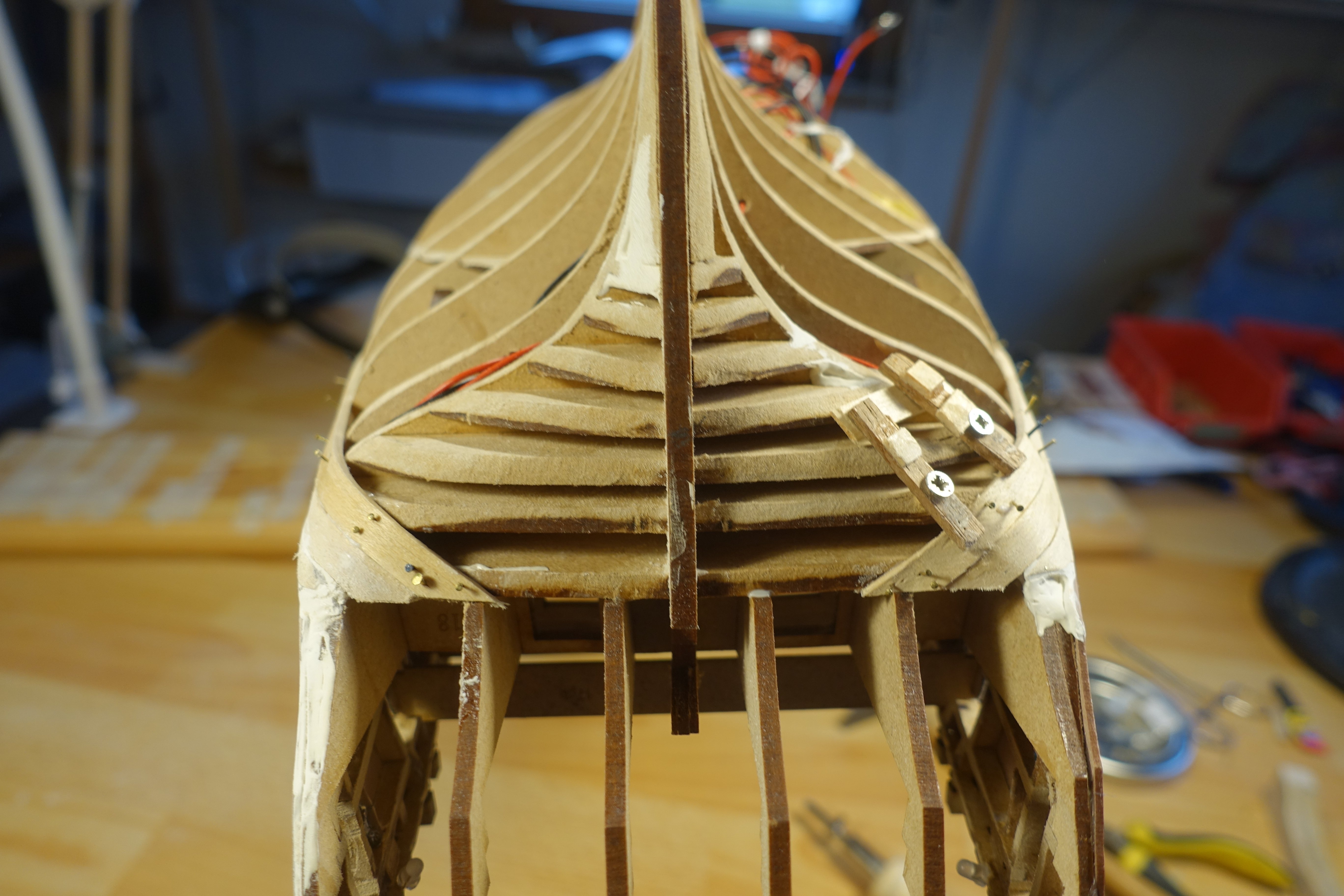
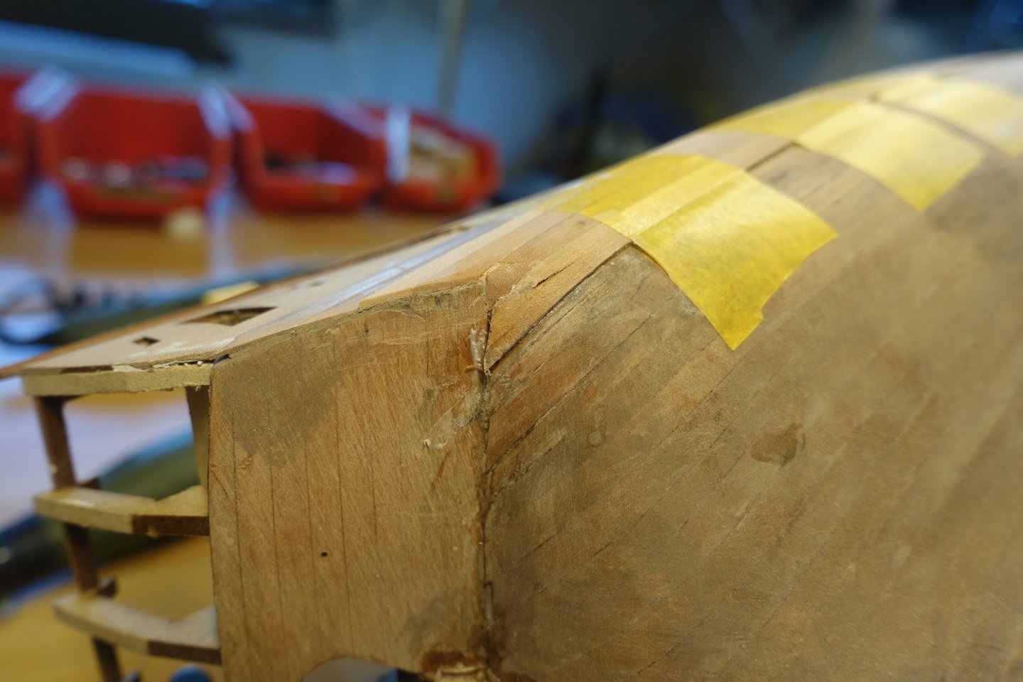
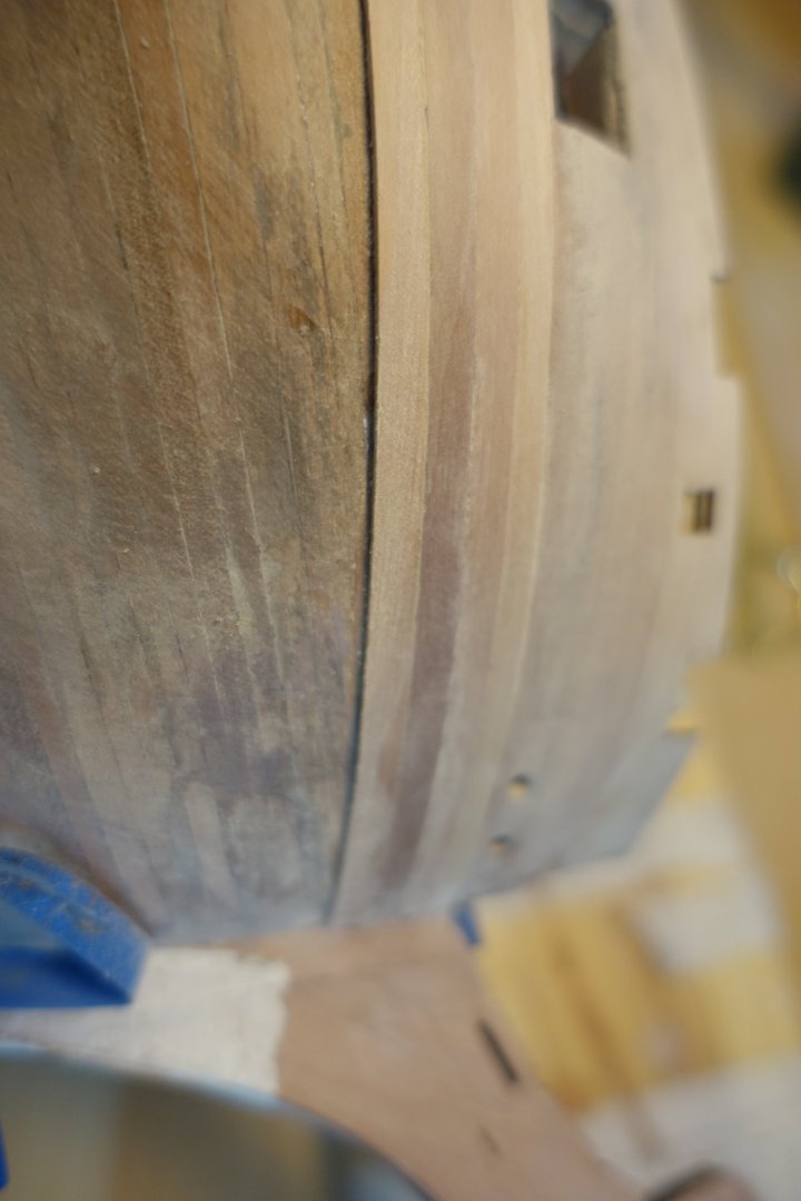
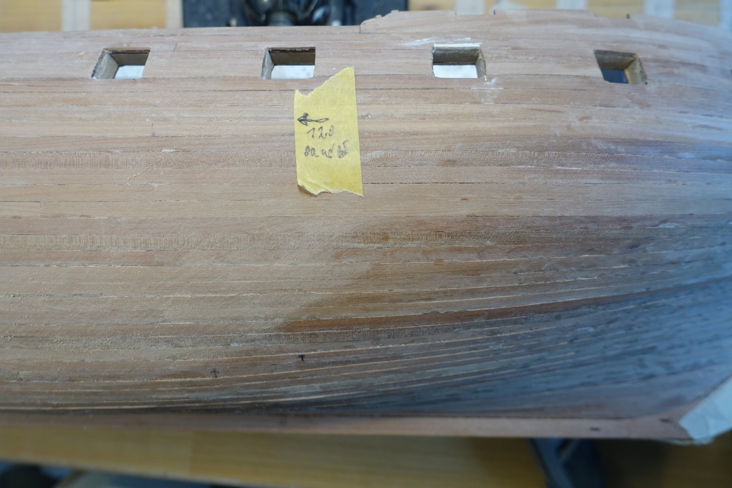
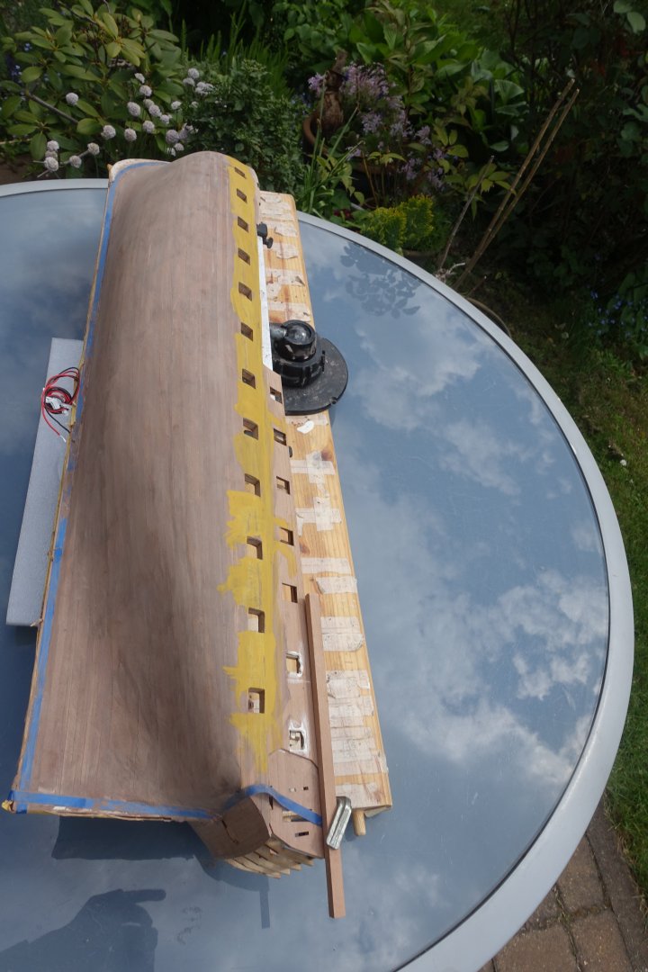
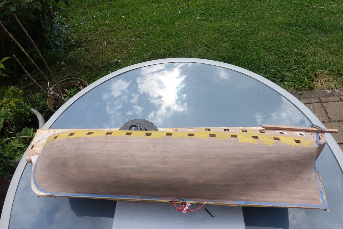
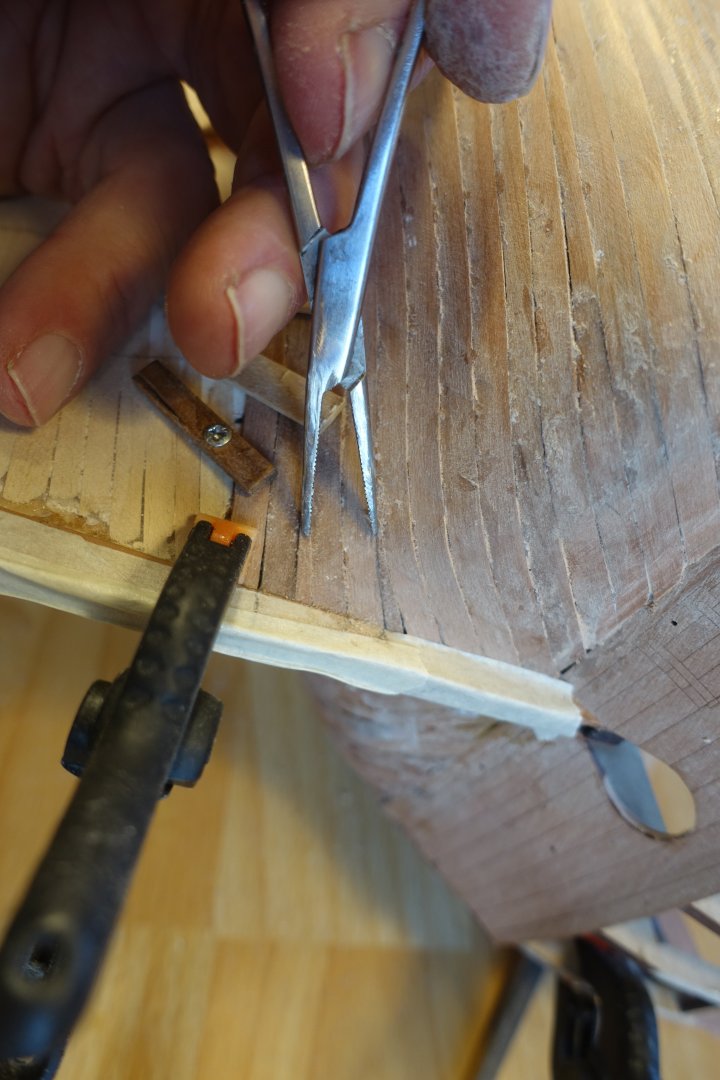
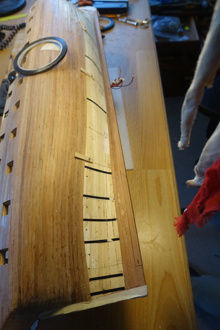
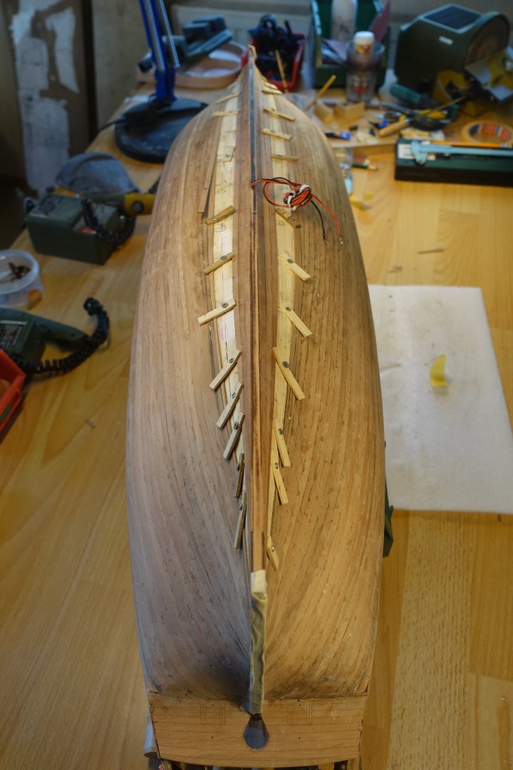
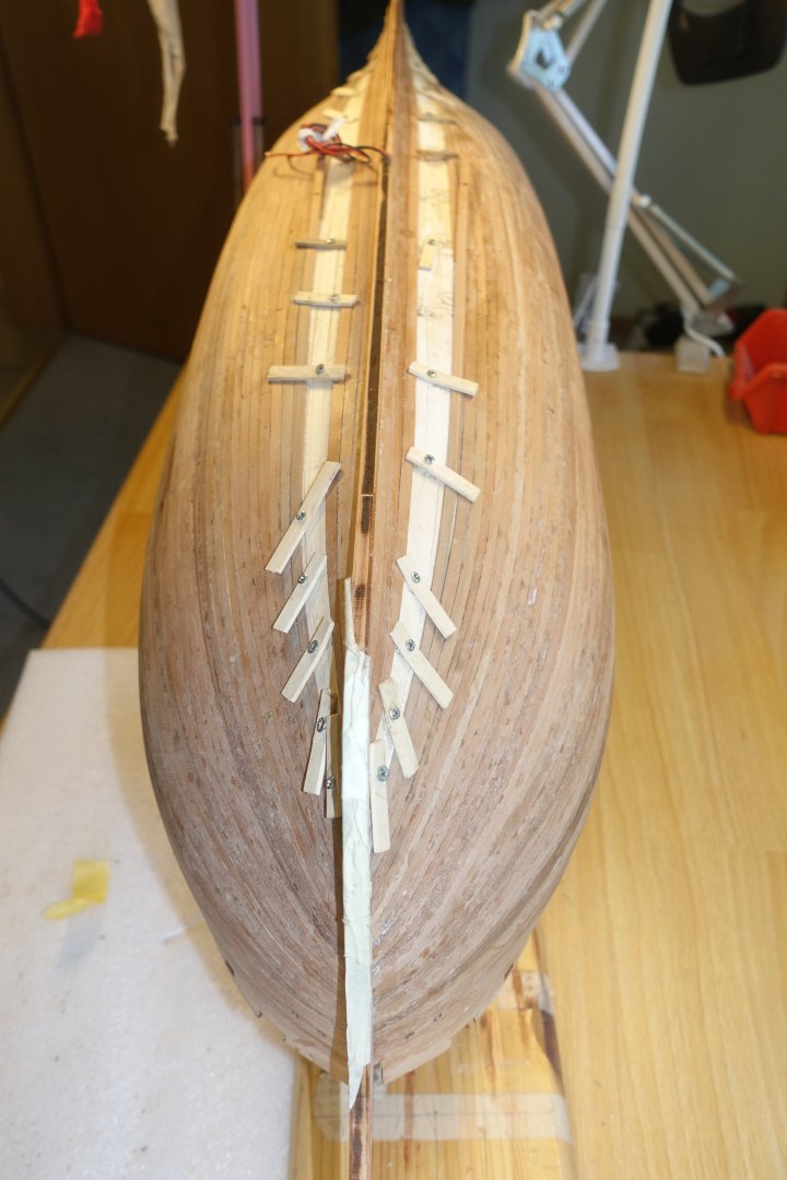
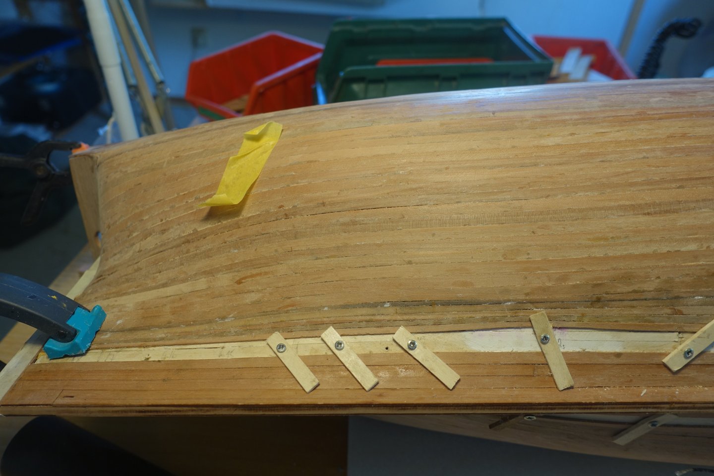
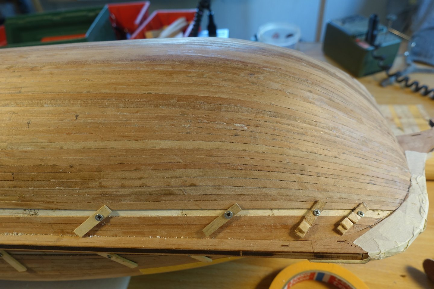
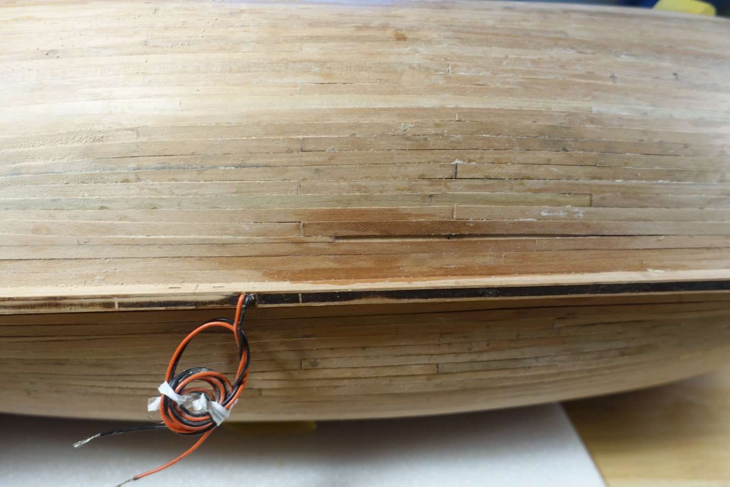
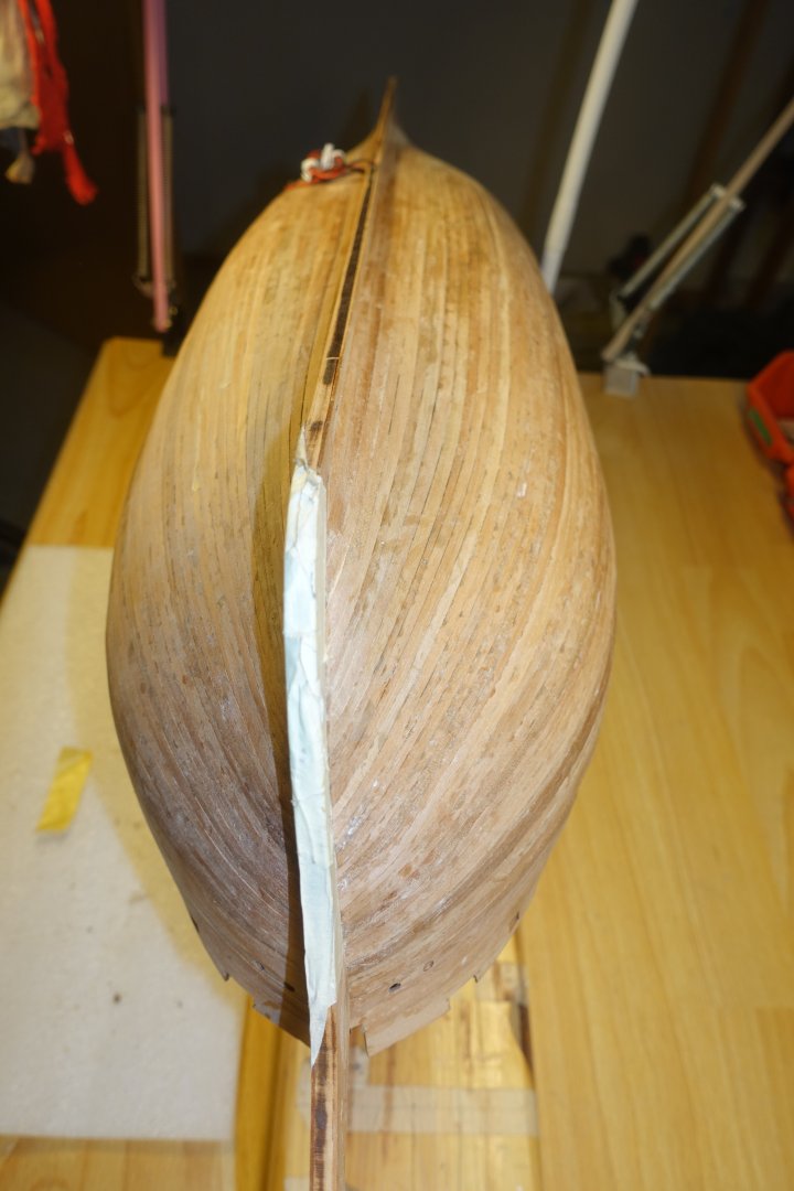
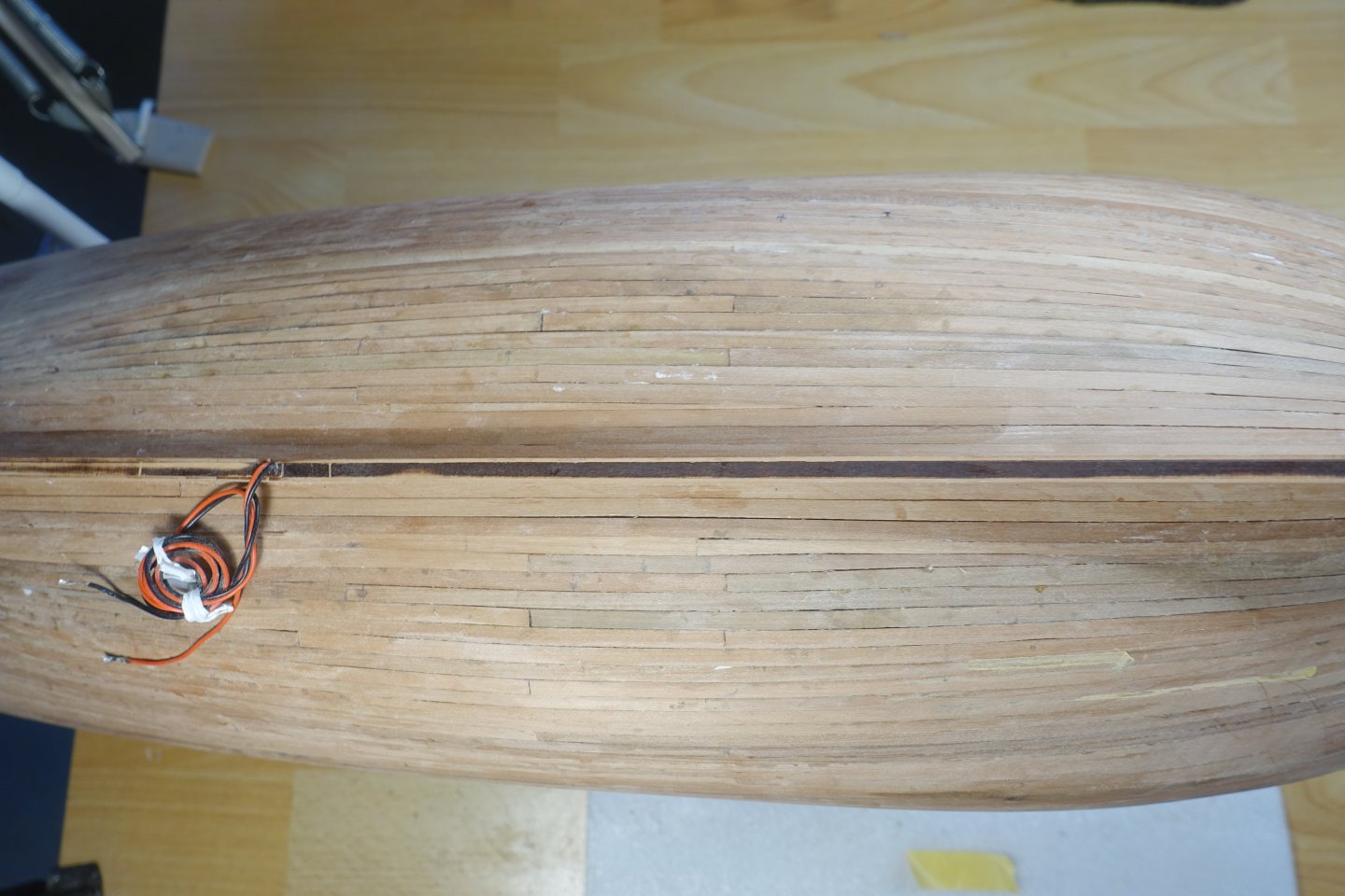
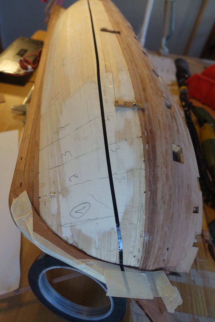
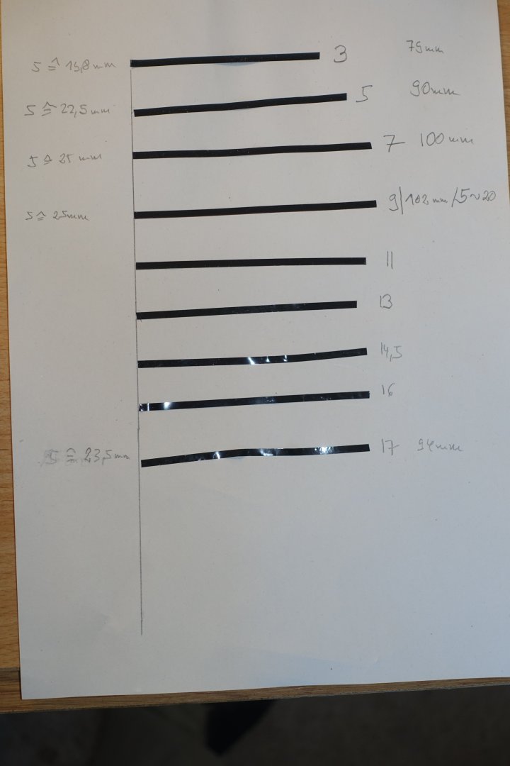
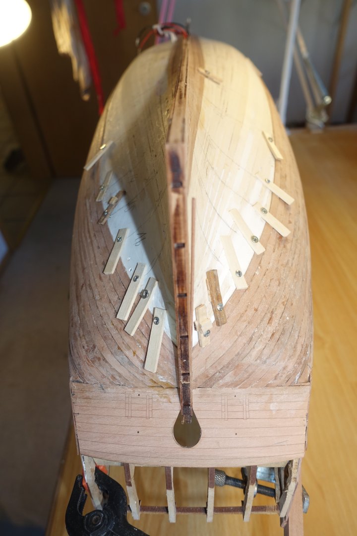
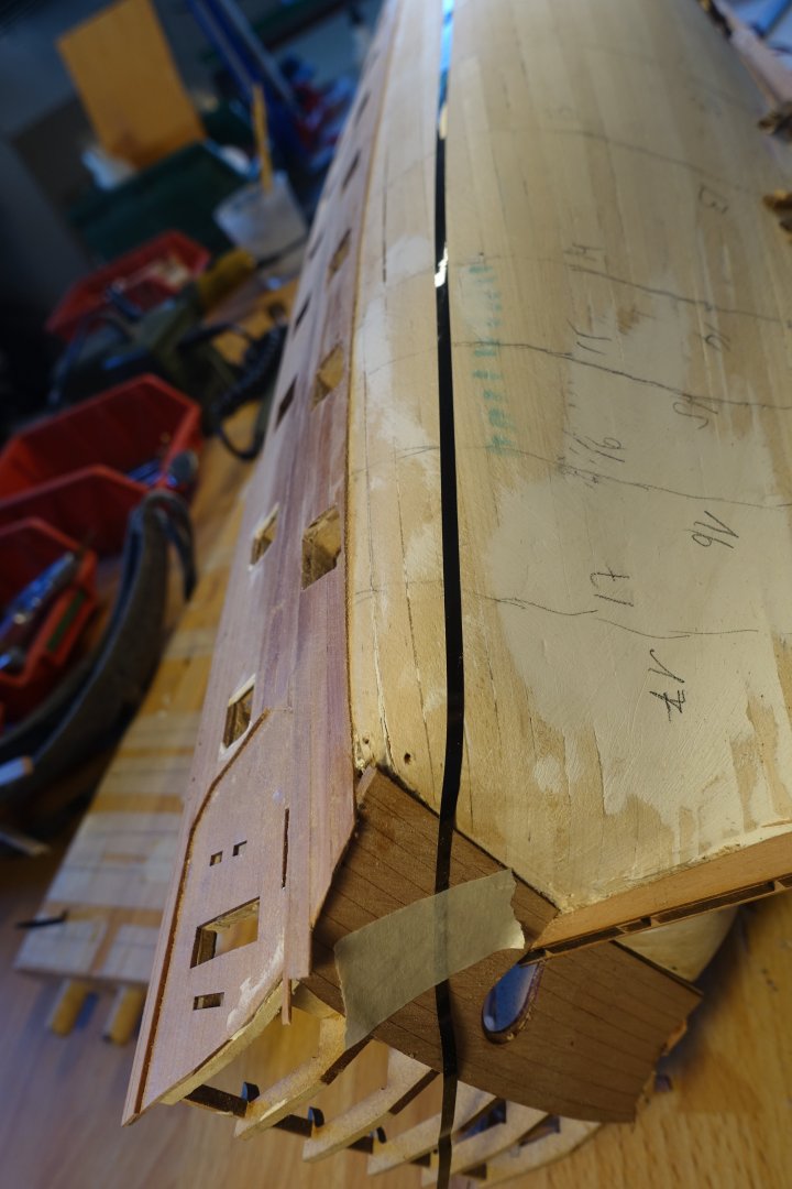
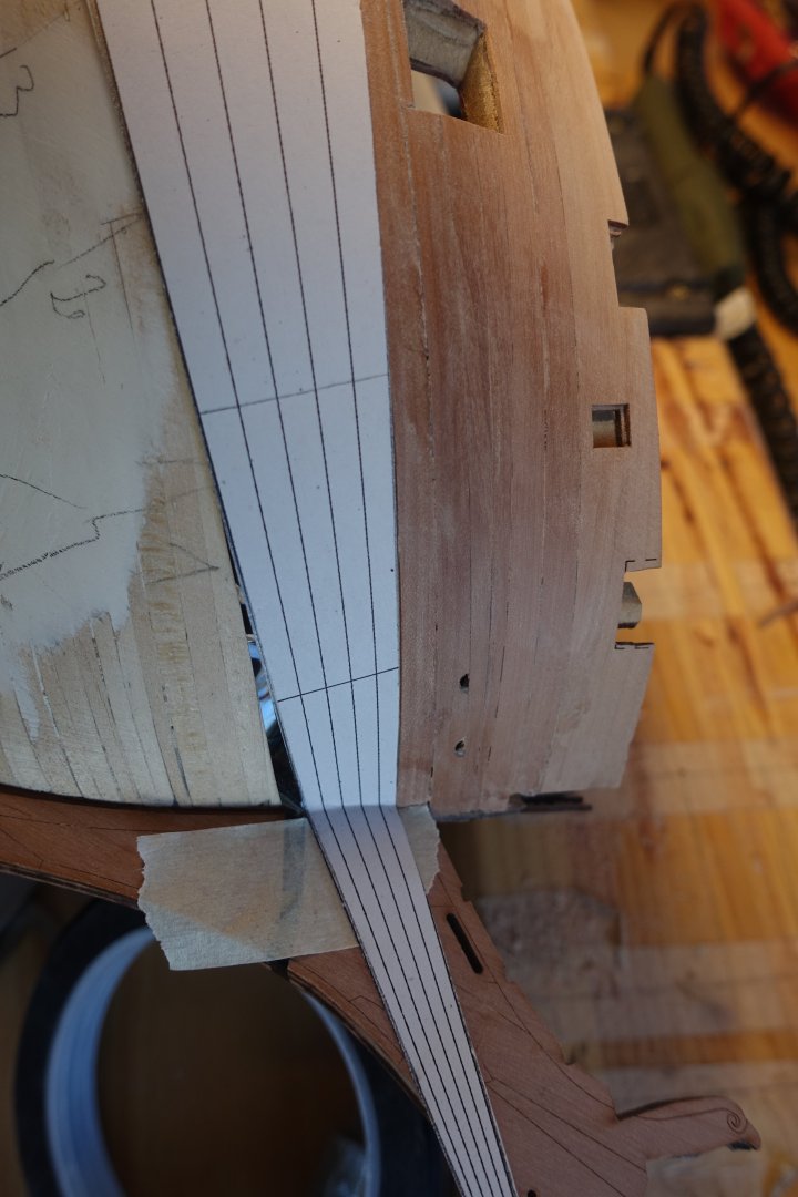
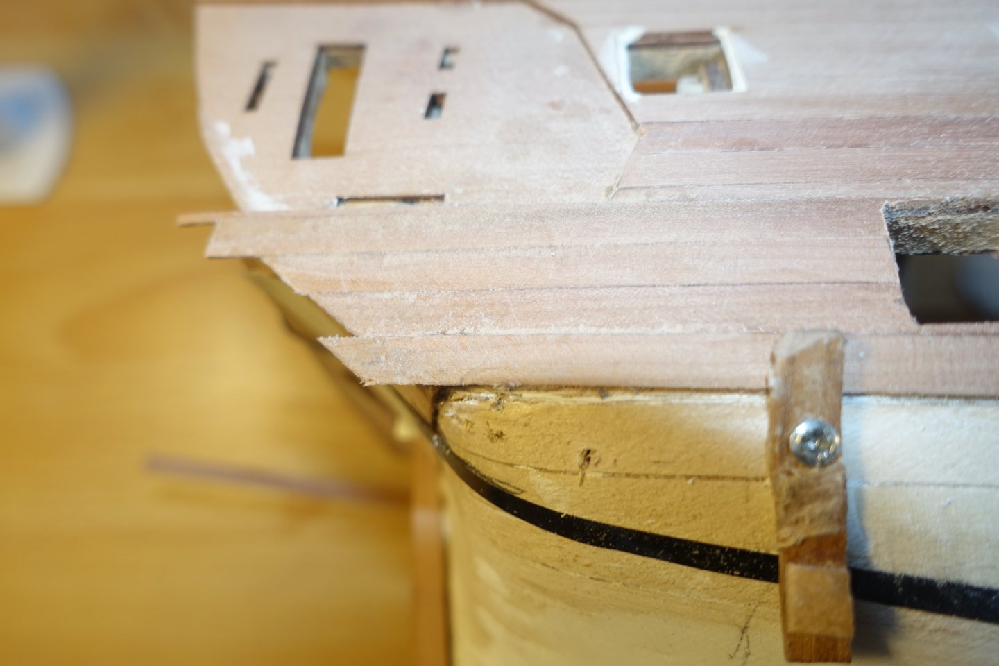
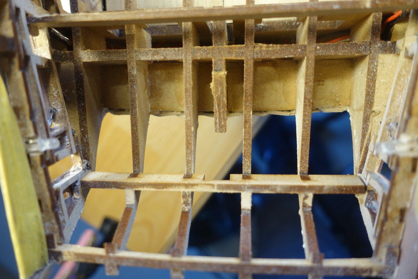
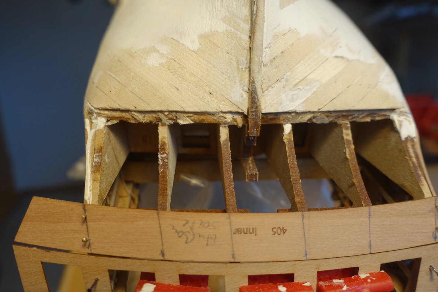
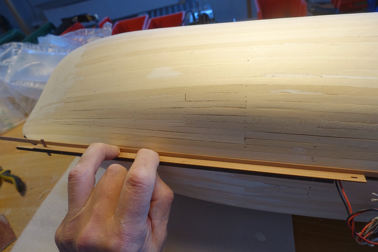
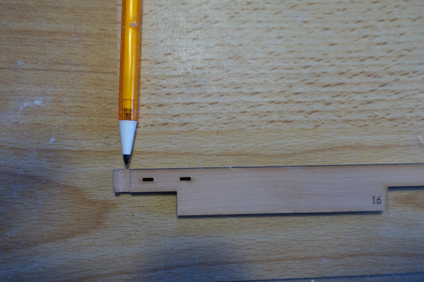
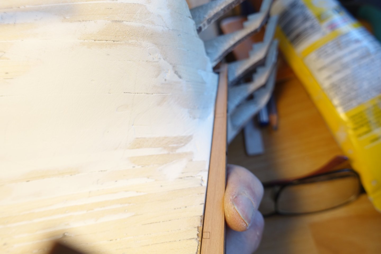
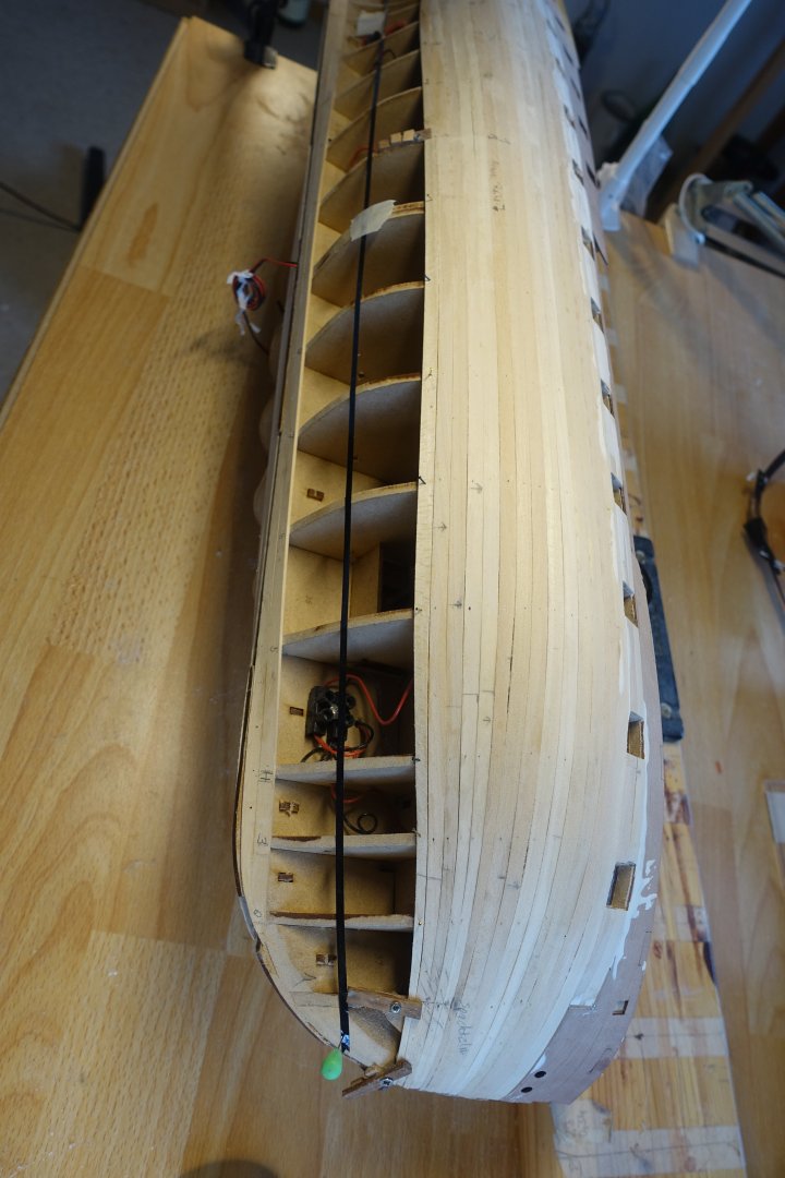
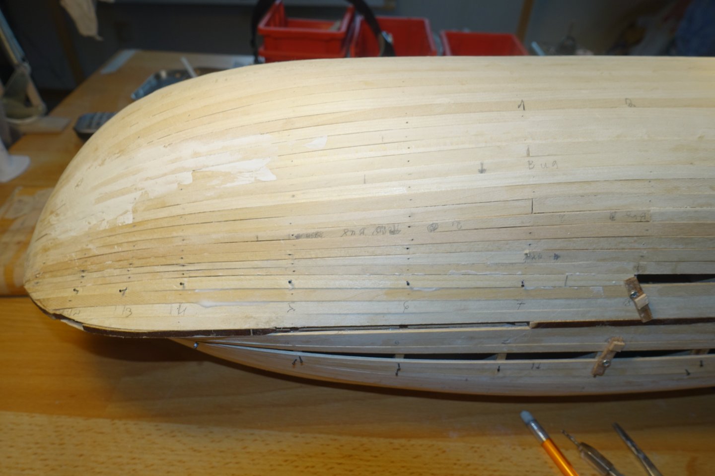
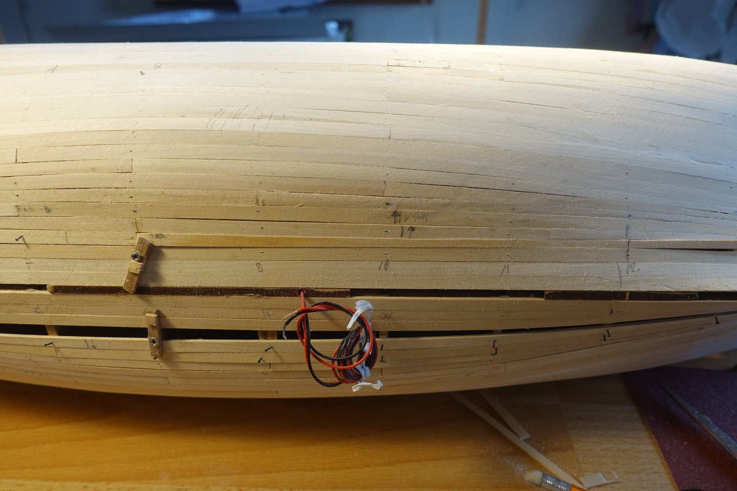
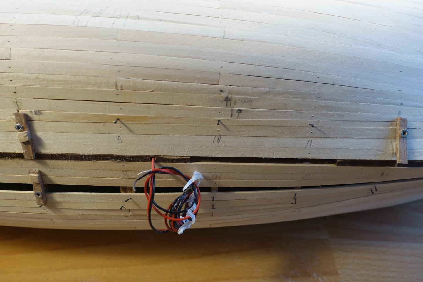
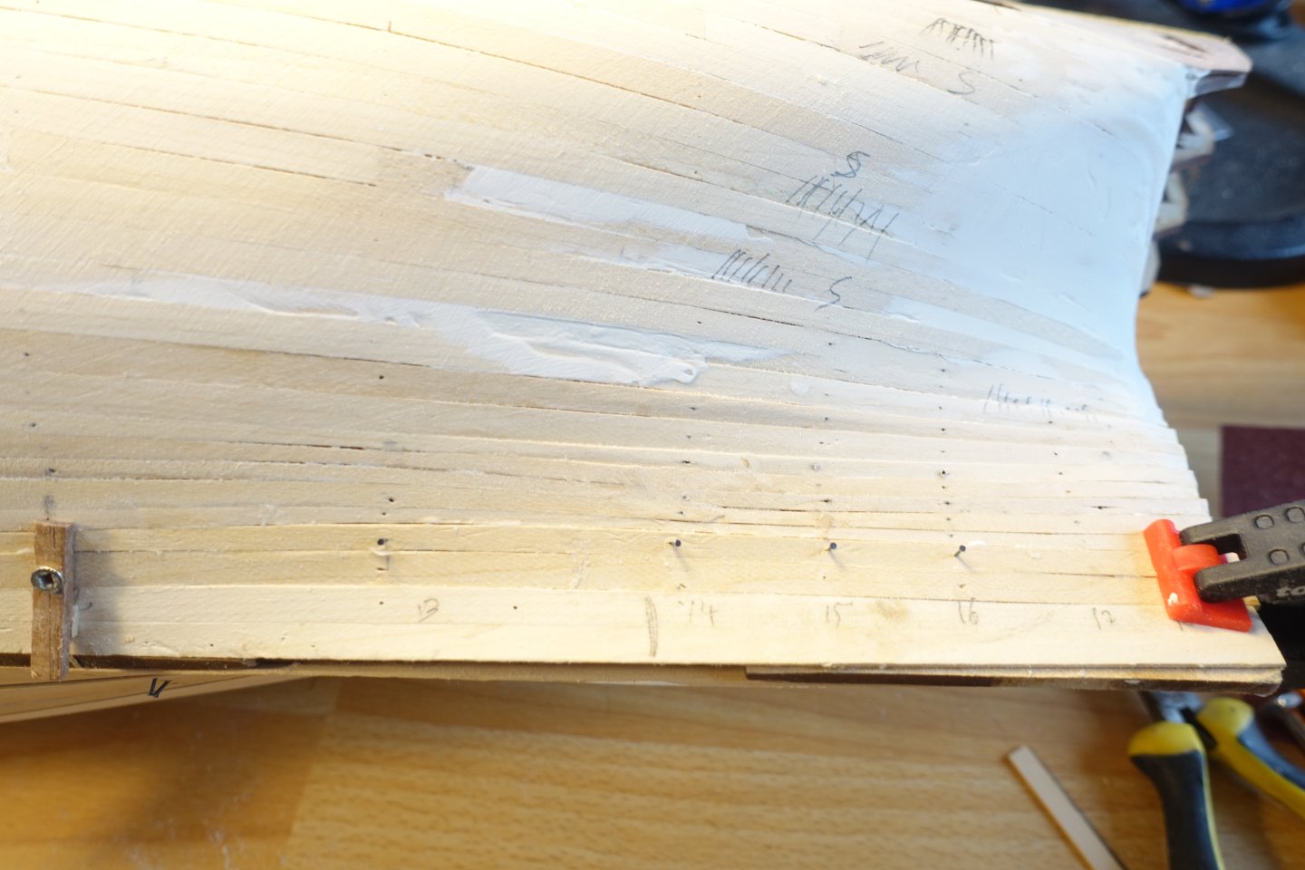
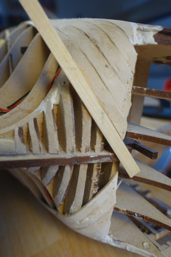
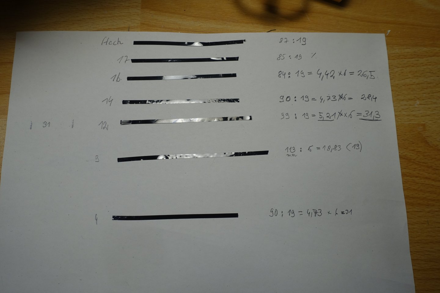
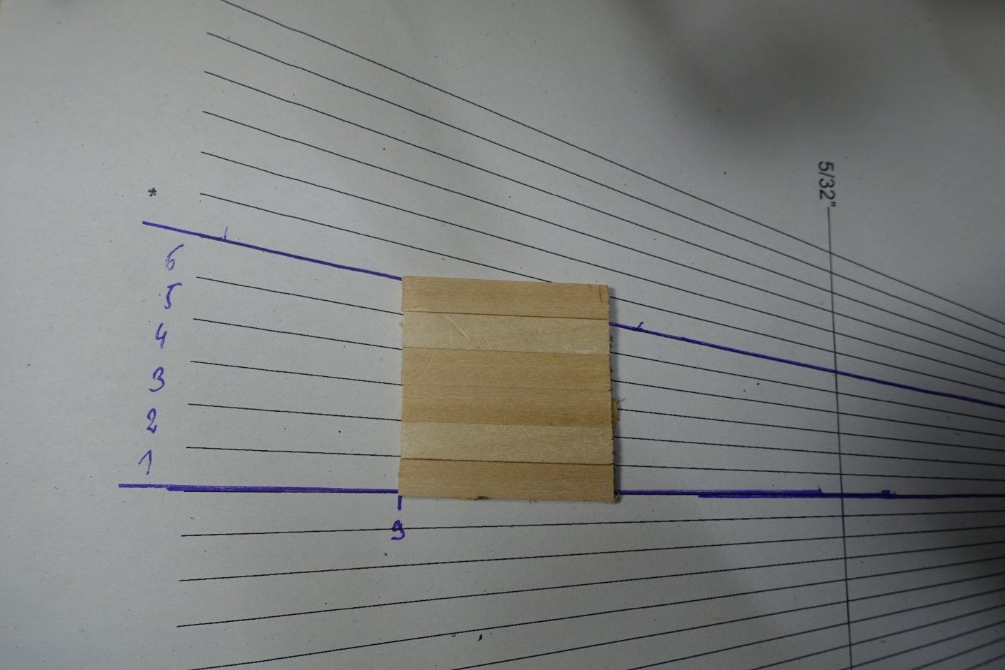
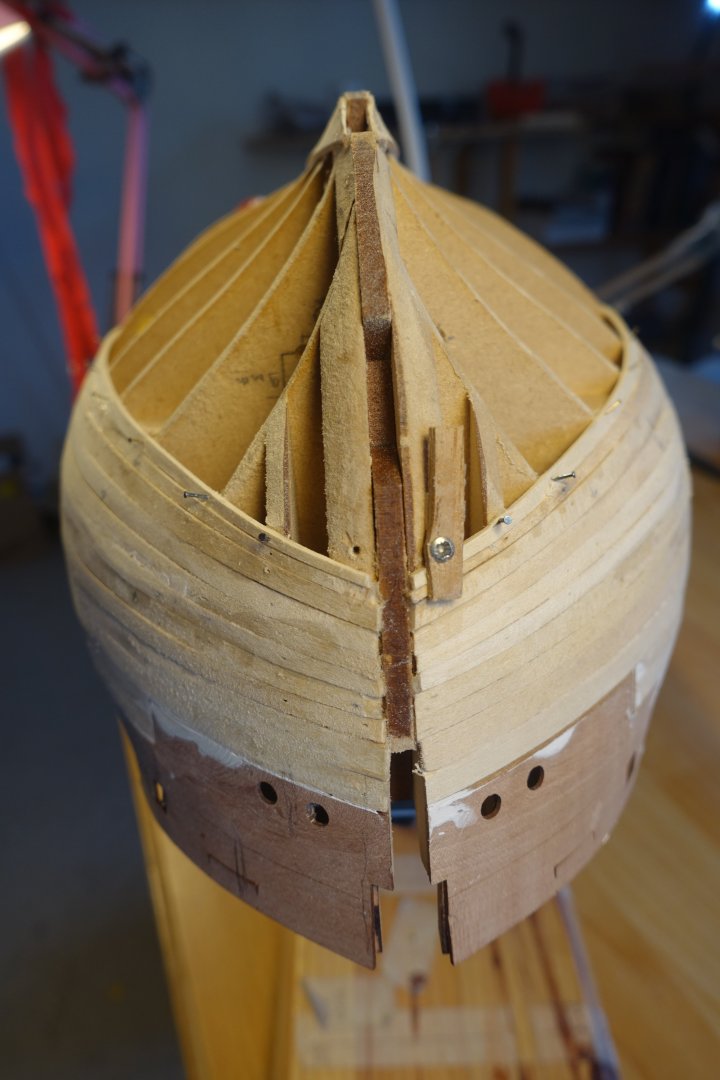
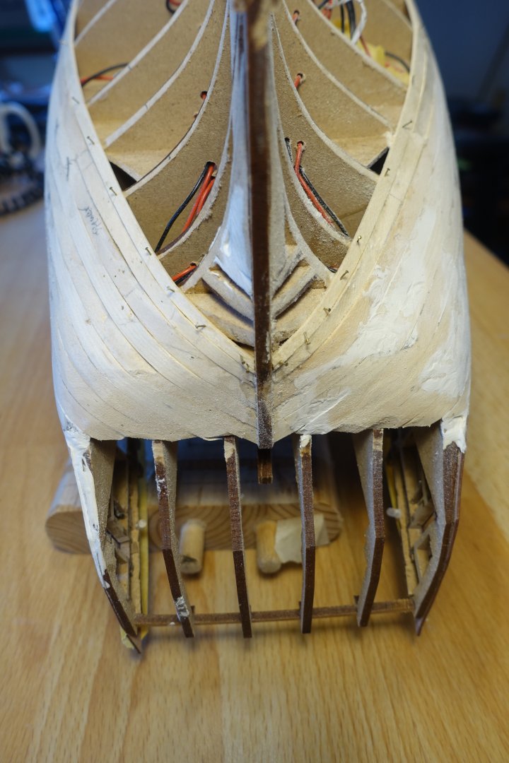
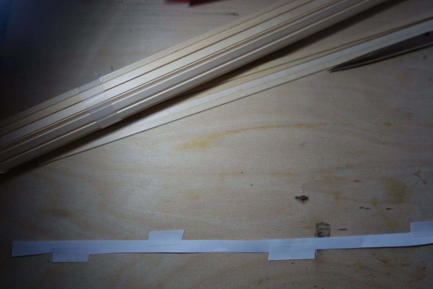
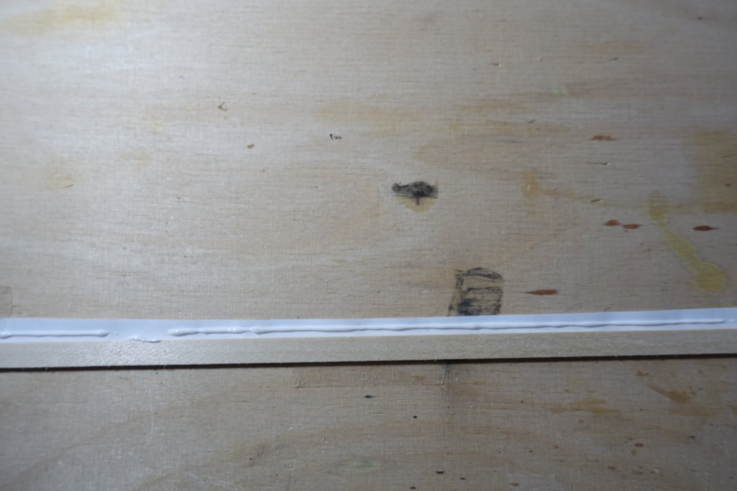
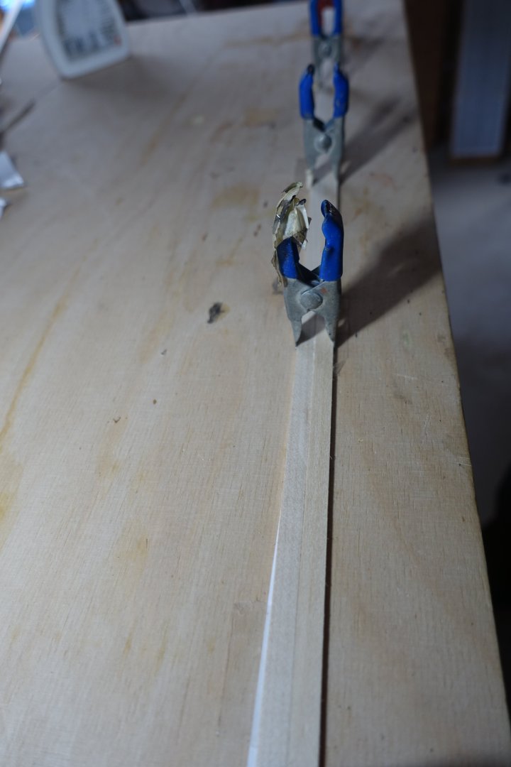
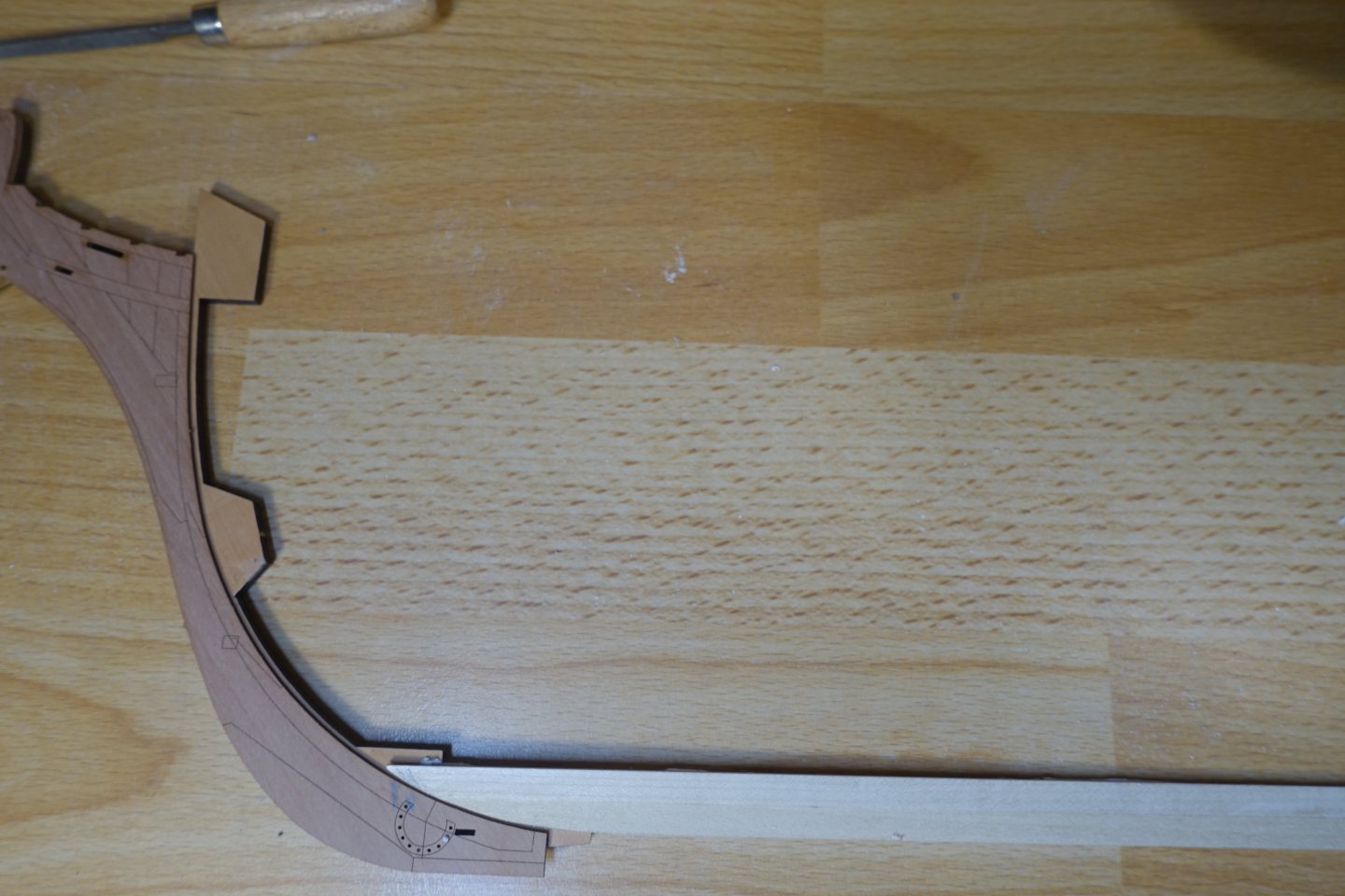
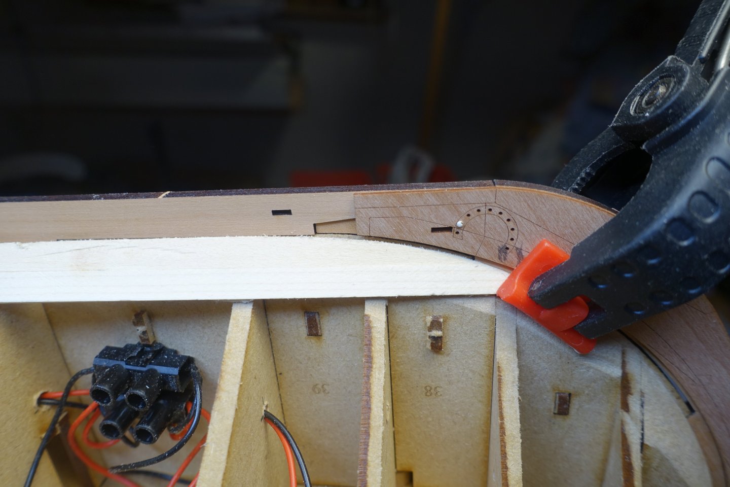
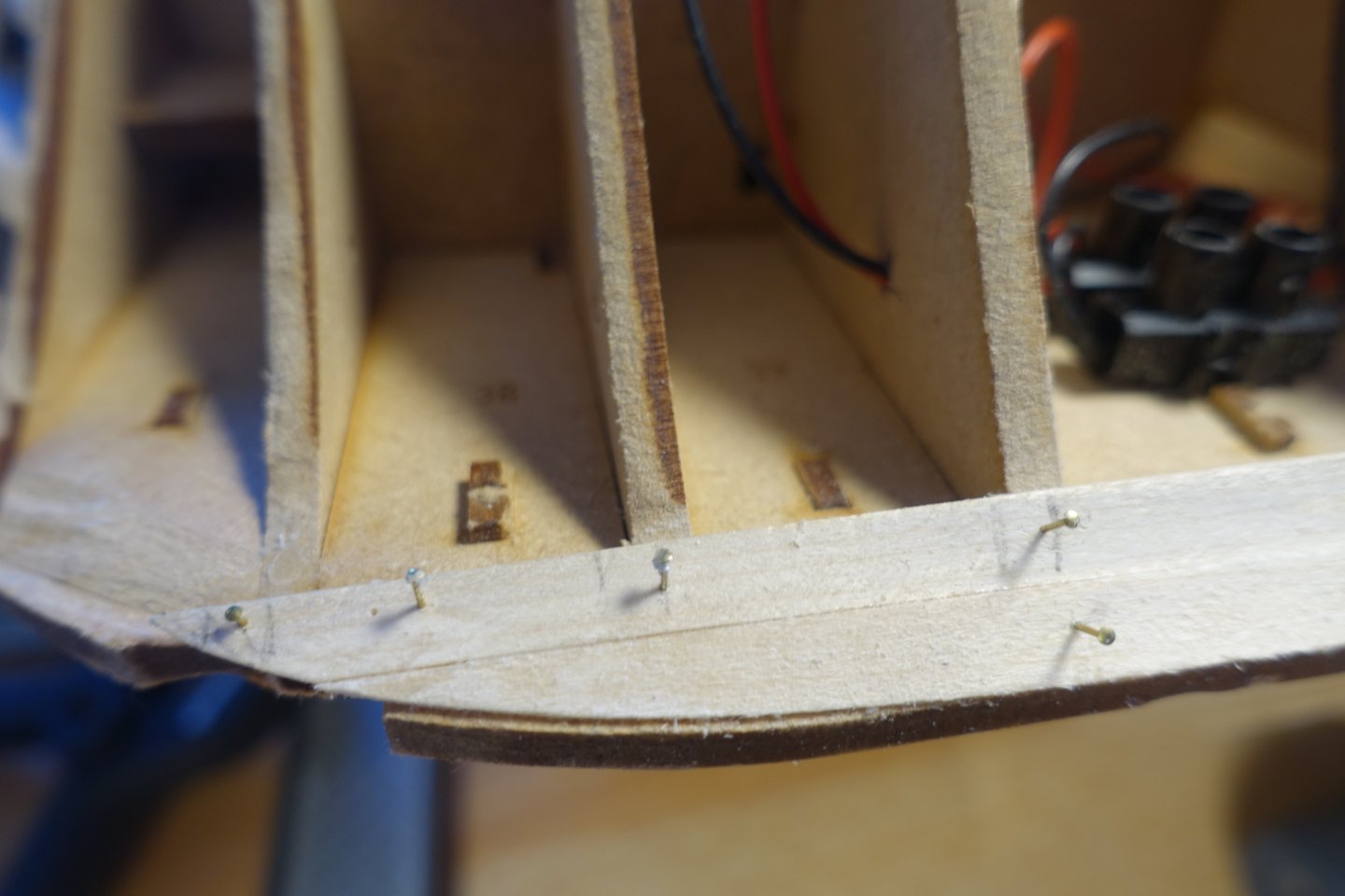
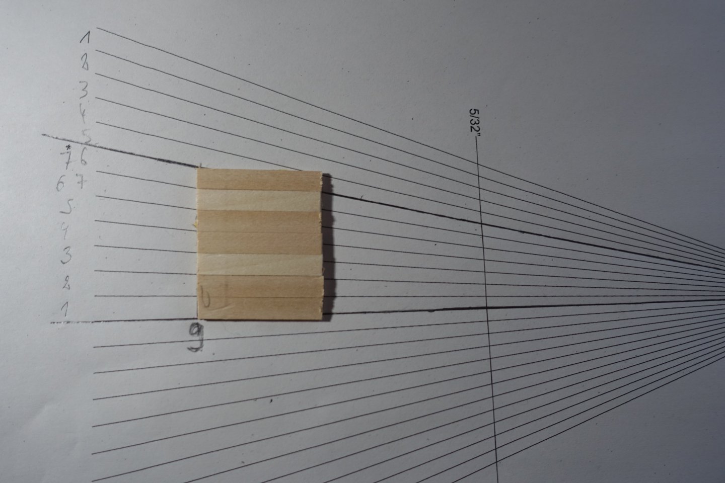
The planking is slowly progressing. First, I added another plank at the top that was not tapered. The gaps in the stern area bothered me a bit more, so I applied a little more putty. Everything is very provisional and will be sanded down further. It makes sense to attach a gaboard plank, especially to such a large hull. However, I didn't have any planks of sufficient width available. So I used a paper strip and double-sided tape to glue two 6 mm planks together to make a 12 mm plank. To better adjust the garboard plank, I provisionally joined the stem with its covering and roughly fitted it in place. Then I marked the positions of the first bulkheads. Incidentally, the stem fits perfectly into the recesses. The garboard plank was first adjusted outside the hull and then on the hull and then glued. However, no glue was applied in the stern area, because here the plank sections will be removed later so that they can merge into the MDF core to allow the stern post to sit correctly. As far as planking is concerned, everyone has their own method. I always think it's good if the first planking already anticipates the second planking and therefore believe that the first planking should be trimmed accordingly. To determine the number of planks still needed, I measured the length at bulkhead 9. The length was 149 mm. With a plank width of 6 mm, this corresponds to 24.8 planks, which is quite a number. So to plank the first section, I glued 7 plank pieces together and marked the width at bulkhead nine and in the area of the rudder post. With the help of the markings, the plank course was marked with a marking tape. 4244 Below the black marking tape, a tape was attached to the bulkheads, on which the respective bulkhead numbers were written. The tape was then removed and glued to a board. To determine the plank width at the respective bulkheads, I used Chuck's Planking fan (see NRG). This was held up to the respective bulkheads, the respective section cut off and glued to the bulkhead position marked on the masking tape. With the help of the markings on the strip, the strip can then be tapered. I always taper in pairs so that the strips on the port and starboard sides are the same. 4272 To position the strips correctly, I marked the cut side. This side will then face the bulwark for all planks. When I join the section of planking that comes from the bow with the section that starts at the stern, I will always offset the contact points according to the scheme that is also used for the deck planking. 4280 Now there are still 24 planks to lay, if I have calculated correctly.


-
Thank you very much, but I'm not sure how the distance between the bulwark and the strip will turn out. I'll continue planking for now. Thank you also for all the work you put into the prototype and the instructions.