Clark
-
Posts
311 -
Joined
-
Last visited
Content Type
Profiles
Forums
Gallery
Events
Everything posted by Clark
-
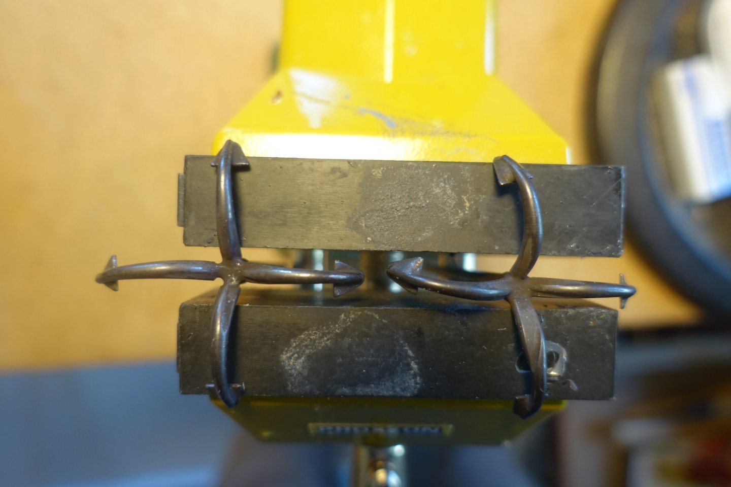
Hi Frank, Not only are the anchors bent, but the right one has a depression on the lower blade arm. I ordered new ones from "Krick" (German specialist dealer), they arrived yesterday and look excellent. I had tried to make anchors myself on a previous ship, but it was not successful. How are you doing with the move? Ships secured? All the best Clark
- 112 replies
-
- 1
-

-
- corel
- reale de france
- (and 1 more)
-
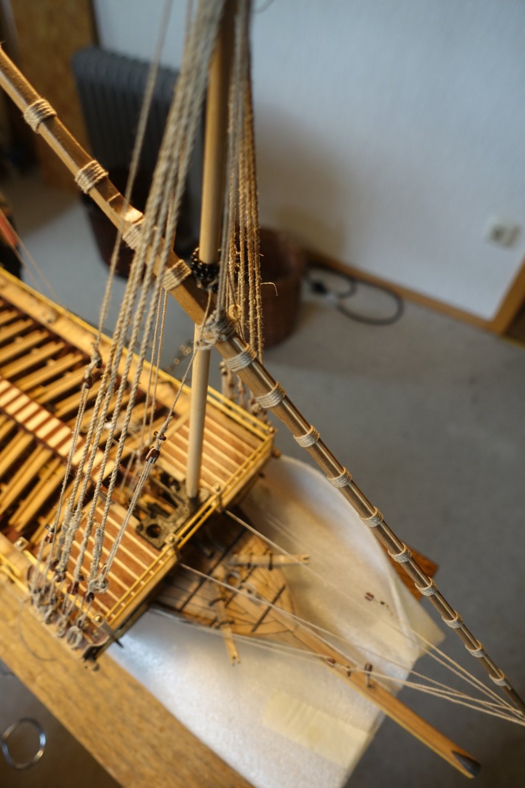
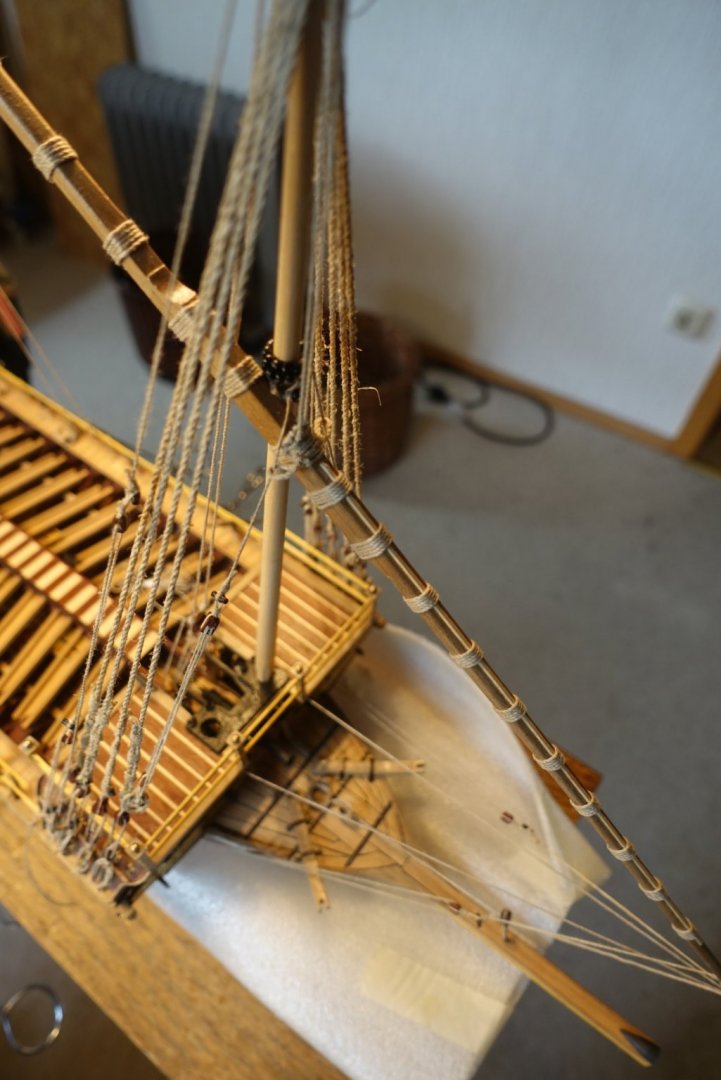
The main lateen yard is now fixed. The first fixation was again done with two small nails, countersunk in the yard. The ropes for the halyard were fixed before. As they pass through the centre aisle and are attached to the pins of the forecastle, they were mounted before the covering the centre aisle. As there are no sails attached, I fixed the yard slightly eased. Actually, I then wanted to continue with the anchors, but found that they were considerably bent and also inaccurately made. Another point that turns me away from Corel.


- 112 replies
-
- 3
-
-
- corel
- reale de france
- (and 1 more)
-
Preordered two weeks ago, Sphinx arrived today. Chris, do you ever sleep? Thank you very, very much! Perfect. Clark
-
Back at the shipyard after a long time. Our house (wood) was in need of an intensive refreshing and touching up, so the warm months were needed for that. The fore lateen yard is now fixed. I pondered for some time whether to show the sails and decided against it. The lateen sails are quite large and catch the eye. Reefed sails usually look rather fake, my attempts with paper etc. on the previous ships were not quite satisfactory. The attachment to the foremast was done with two small nails (unfortunately no photo taken), so that the rigging was then easier to attach. I partly deviated from the Corel plan with regard to the rigging and the belaying, as some things seemed illogical to me (conflict with the oars).

- 112 replies
-
- 4
-
-
- corel
- reale de france
- (and 1 more)
-
Thank you very much for the quick reply. It is more than understandable that you want to be on the safe side. I will exercise patience then. Good luck and success to you and James with the wonderful model. Clark
- 355 replies
-
- 3
-
-
- vanguard models
- Sphinx
- (and 1 more)
-
Is it already possible to send an advance order? Clark
- 355 replies
-
- 3
-
-
- vanguard models
- Sphinx
- (and 1 more)
-
Good idea not to fix the guns, it will pay off at the latest when the shrouds are fixed, own experience. Clark
- 510 replies
-
- 1
-
-
- reale de france
- corel
- (and 1 more)
-
Hi Frank, glad you are back. Looks great. You are right not to fix the pots at this stage. I had to remove the ones in my build since they as they trembled dangerously when the ship was moved. Clark
- 510 replies
-
- 1
-
-
- reale de france
- corel
- (and 1 more)
-
Hi Michael, I am also following your blog. It is a different approach. I especially like that you show the sails secured. When I get to that point, I'll ask a few more questions on your blog. I assume, however, that you are then finished with your Reale. Continue to have fun Clark
- 112 replies
-
- 1
-
-
- corel
- reale de france
- (and 1 more)
-
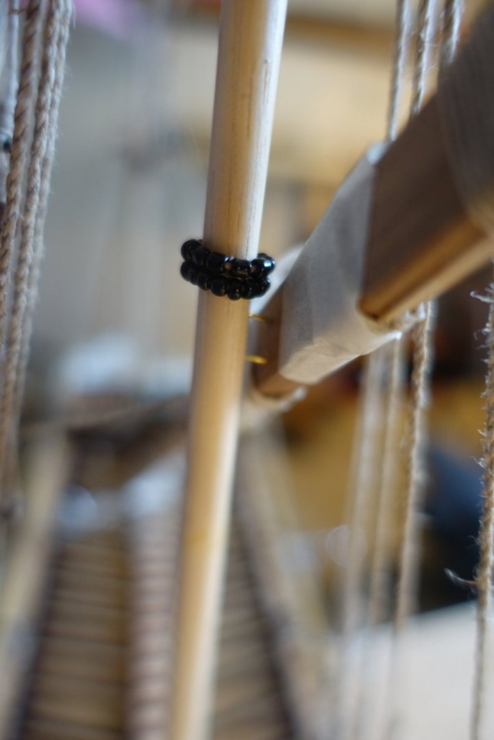
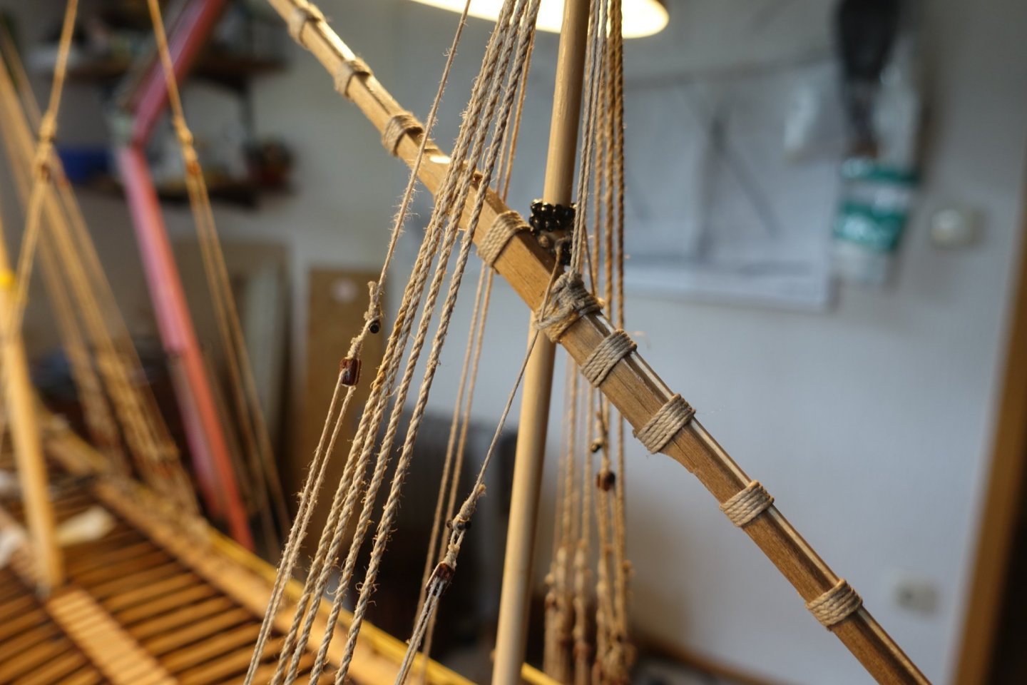
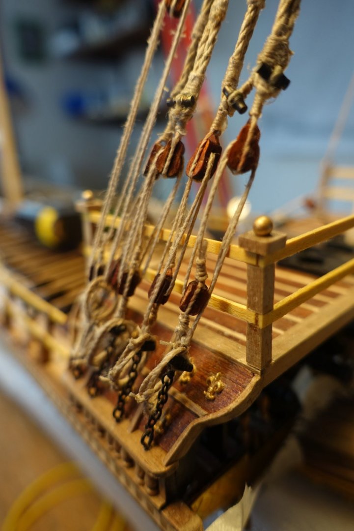
Main mast was prepared and fixed similarly to the foremast. A little bit surprising for me, backstays have to be fixed at the first chains/toggles (seen from the bow) when following the description of corel. I followed it. The fifth chains/toggles are still left free for the later attachment of the rack lines. Clark
- 112 replies
-
- 2
-
-
- corel
- reale de france
- (and 1 more)
-
Swann Morton chisel blades.
Clark replied to harlequin's topic in Modeling tools and Workshop Equipment
Sharpening works quite well when using the sandpaper tools delivered by proxxon. I got both needles and blades sharp enough . There is also a rotating sharpening stone available by proxxon I usually start with the blades. Clark -
Proud owner of a Dremmel drill stand
Clark replied to DaveBaxt's topic in Modeling tools and Workshop Equipment
Hi Dave, hi wefalk Using the vice of proxxon makes drilling and even sanding really easy but I would agree that fixing to the drilling table is a bit challenging in that you have to be sure to adjust it rectangular. I put a long strip (100cm) in the vice (MS4), adjusted the drilling table (KT70) rectangular to the edge of the work disk and measured and adjusted the deviation of the strip of the edge of the working disk. When no deviation was visible, screws were tightened. Clark -
Thanks!!
-
Thanks, the Reale is a great challenge in general. Good luck with your build. Clark
-
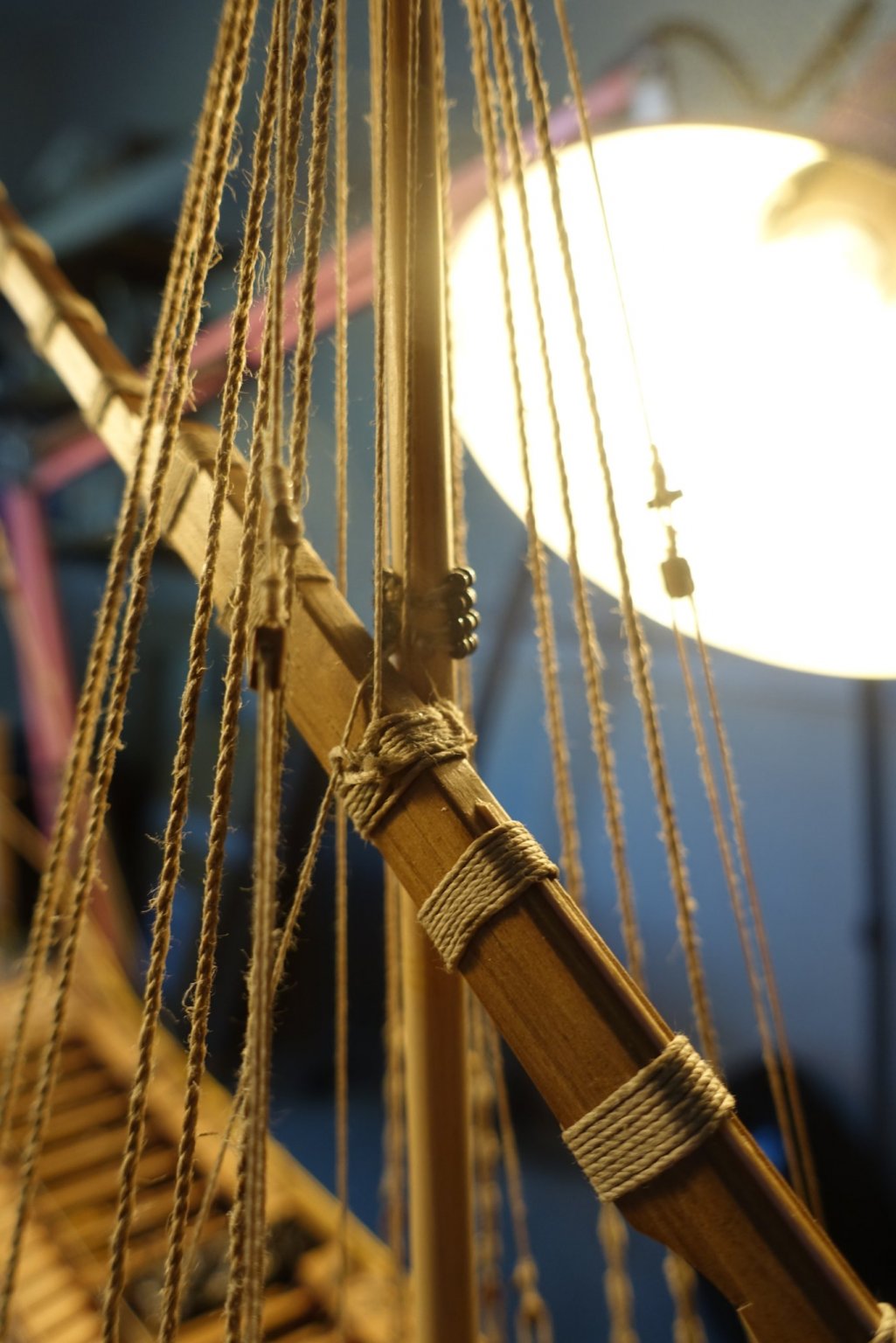
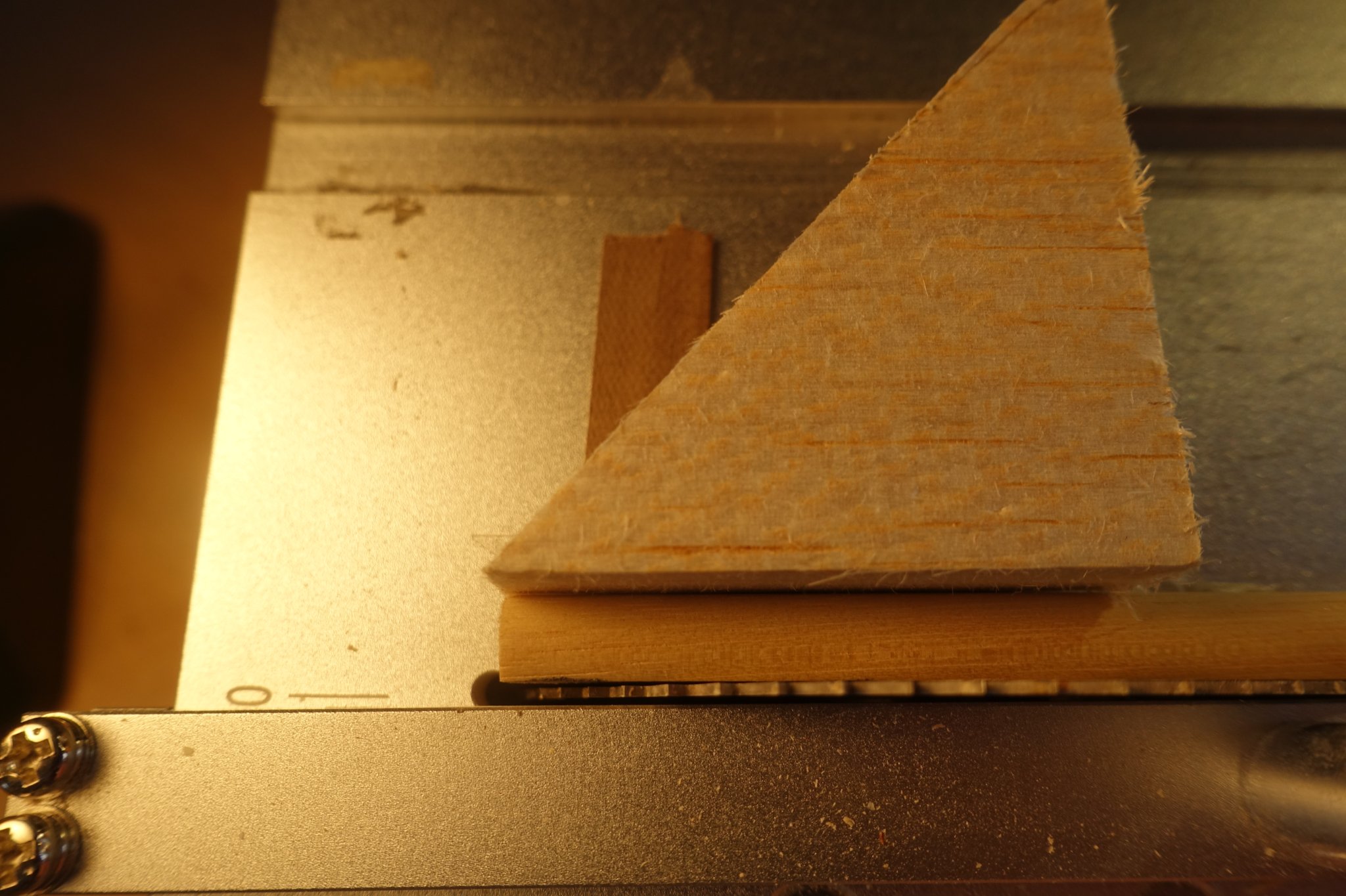
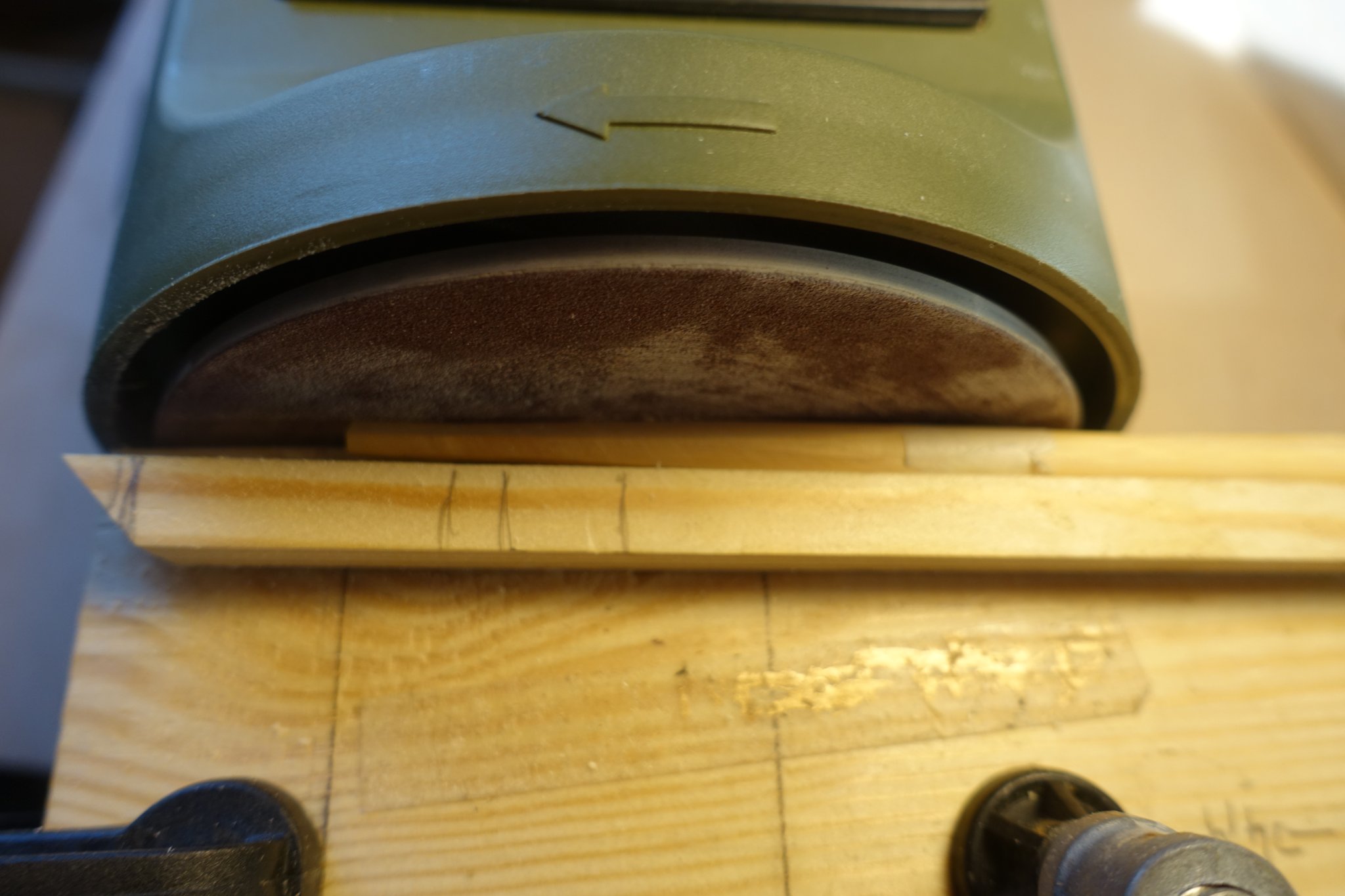
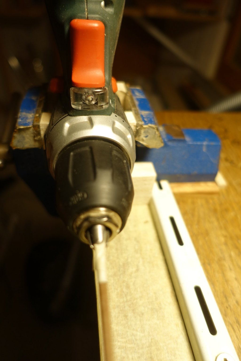
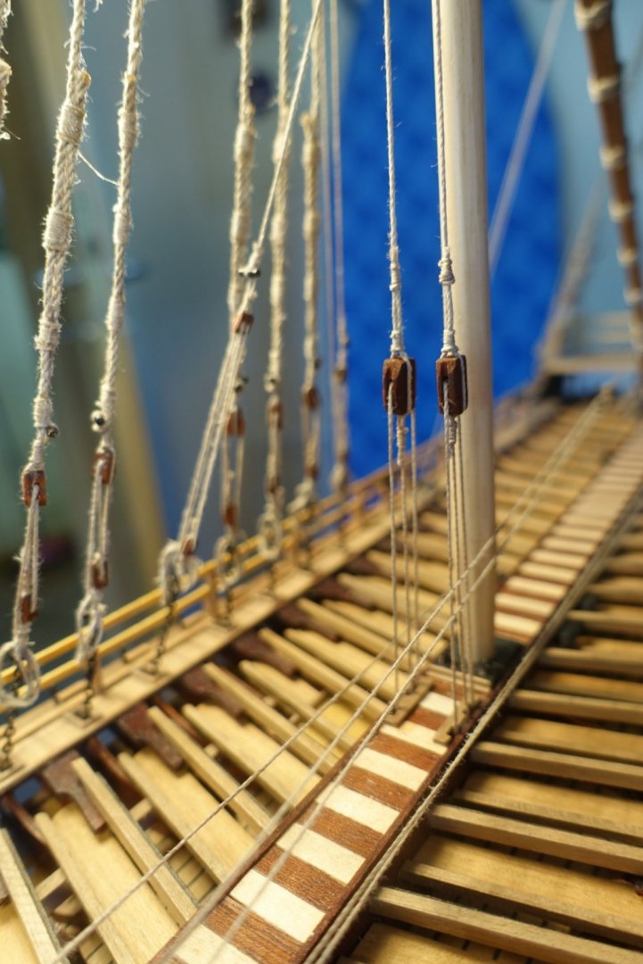
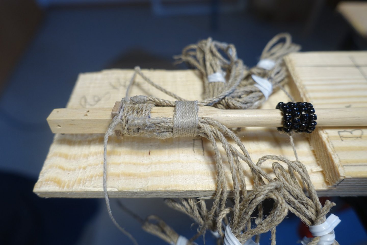
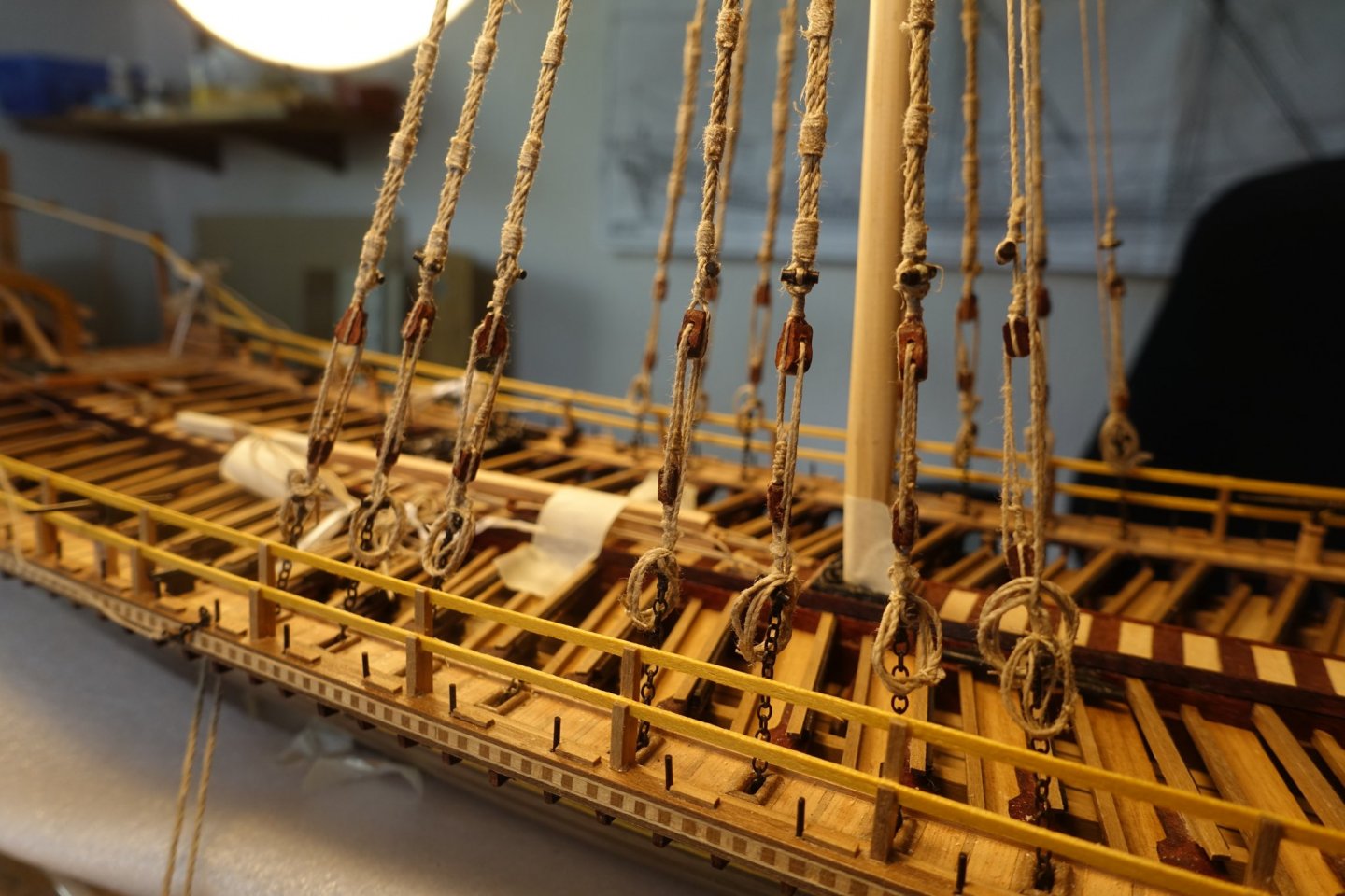
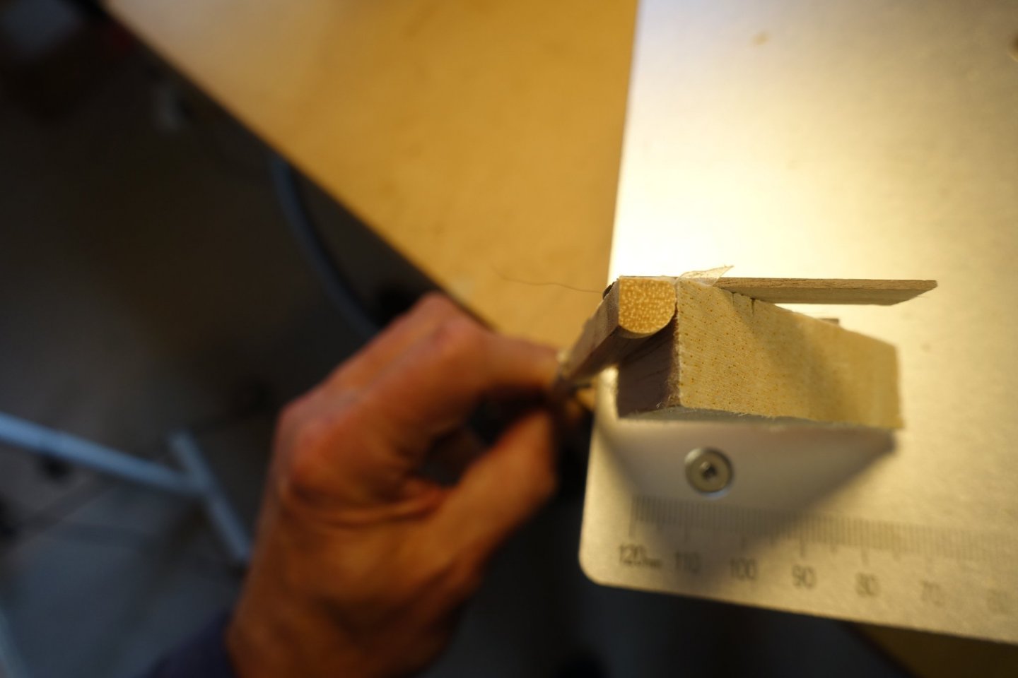
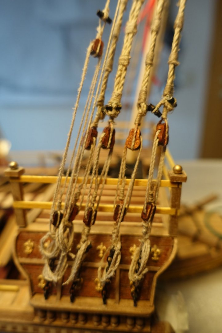
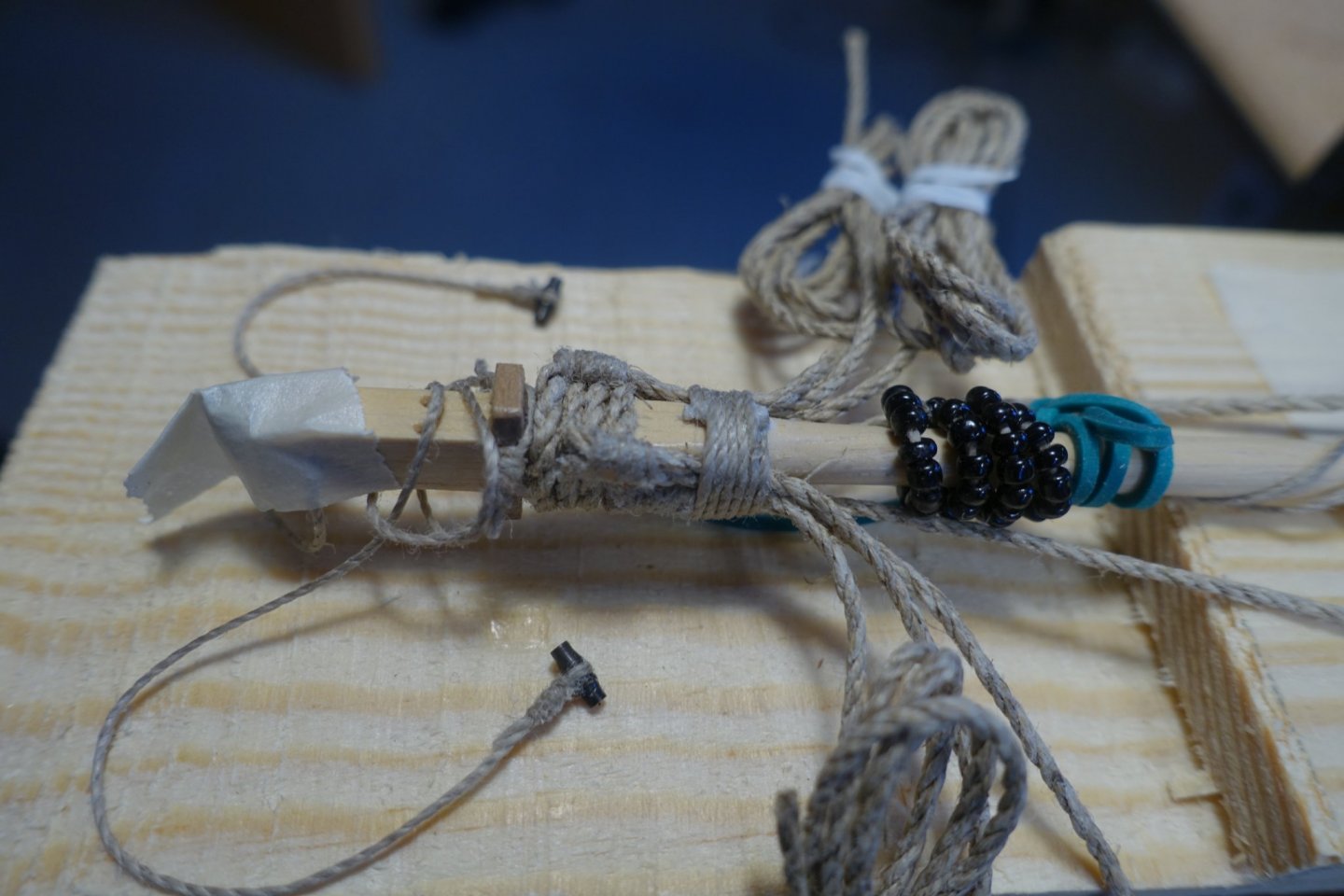
I have started preparing the foremast. As always this takes sone time. Progress is not immediately visible. Upper end of the mast is quadratic. I used the table saw to get it in shape. After making it quadratic I bevelled the mast using the “lathe” described above. Lower end of the mast has to be shaped octogonal and bevelled. I glued a wooden trim on a base with 3° deviation to form a guide bar and adjusted it to a disc sander. To get the mast rotated by 45° and in agreement with the quadratic end, I fixed the quadratic end of the mast in a small vice. Before adjusting the masts, I prepared all the lines of shrouds and back stays. I found it difficult to fix the toggles. Thus, I drilled holes with smaller diameter than the middle of the toggles to put ~1/3 of the toggles in it. Upper end of the toggles end was fixed by a trim. It made handling of the toggles much easier. All lines were pulled through bee wax. Racks were also added before gluing the masts in place at this stage.


- 112 replies
-
- 4
-
-
- corel
- reale de france
- (and 1 more)
-
Happened to me even when I was younger and fingers more flexible.
- 355 replies
-
- 4
-
-
- vanguard models
- Sphinx
- (and 1 more)
-
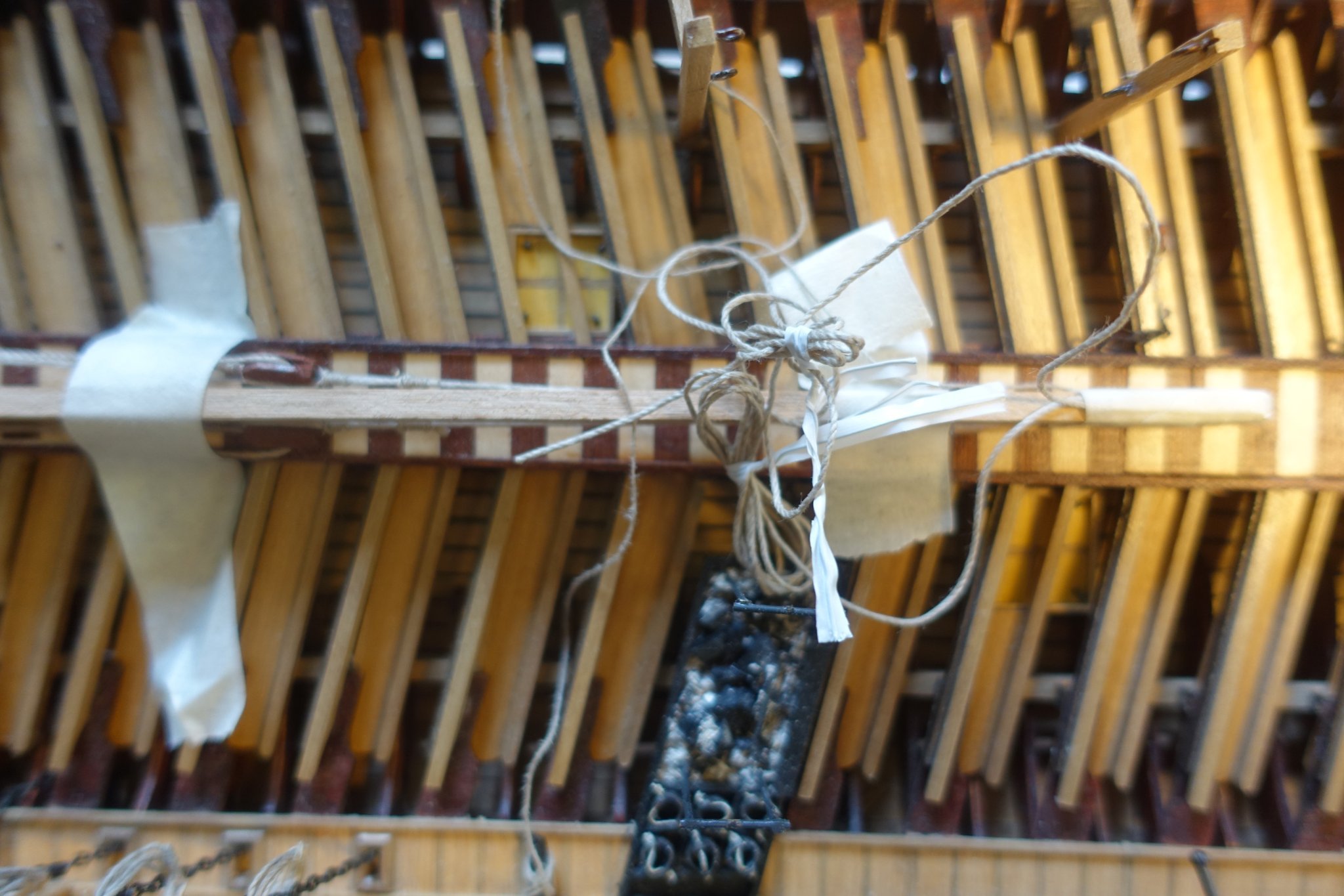
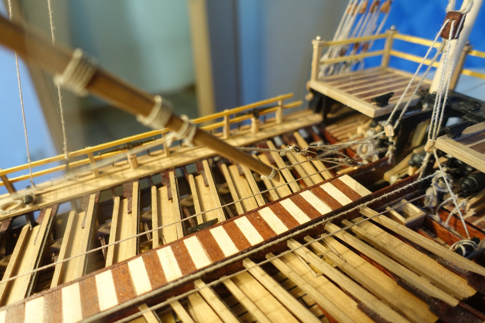
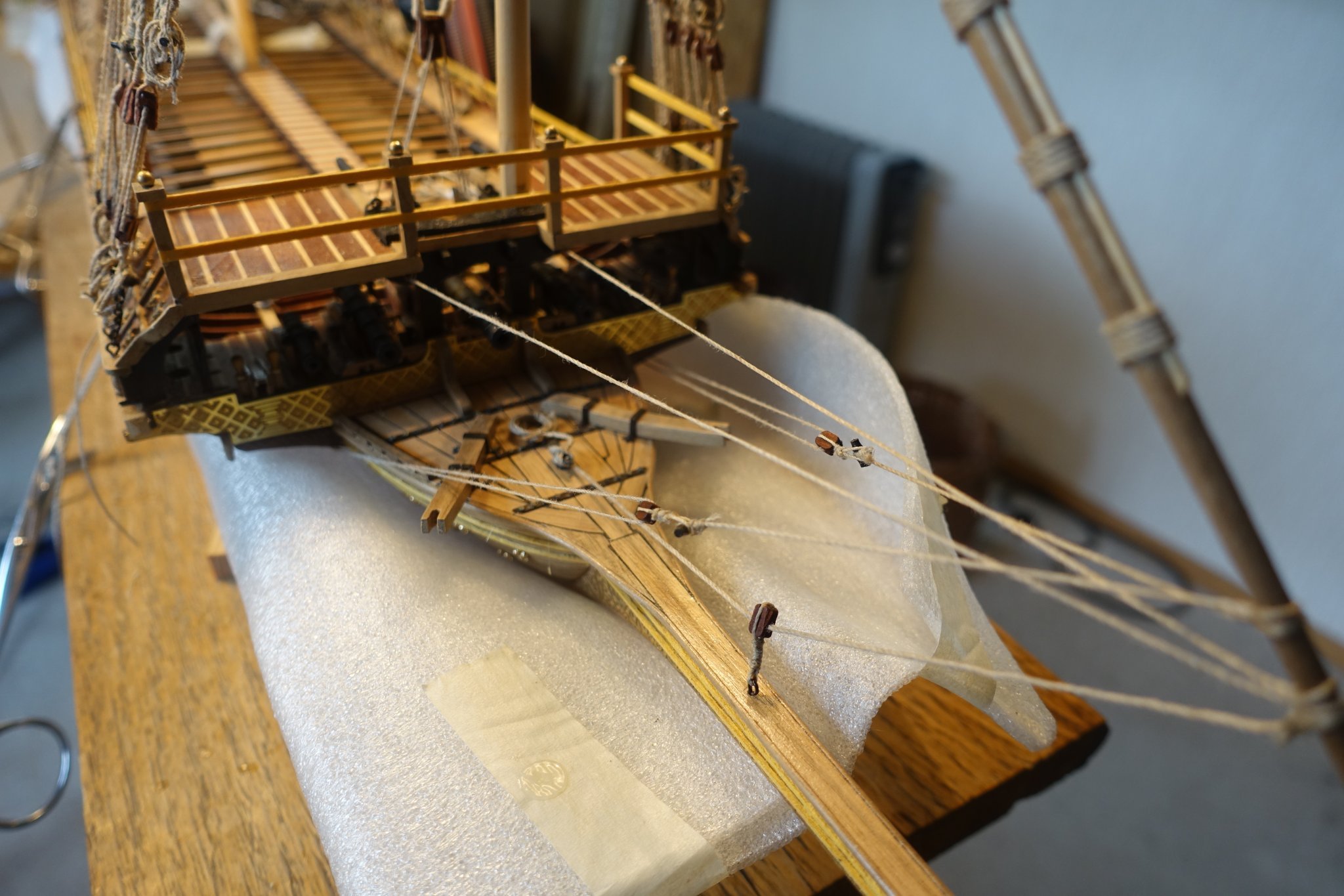
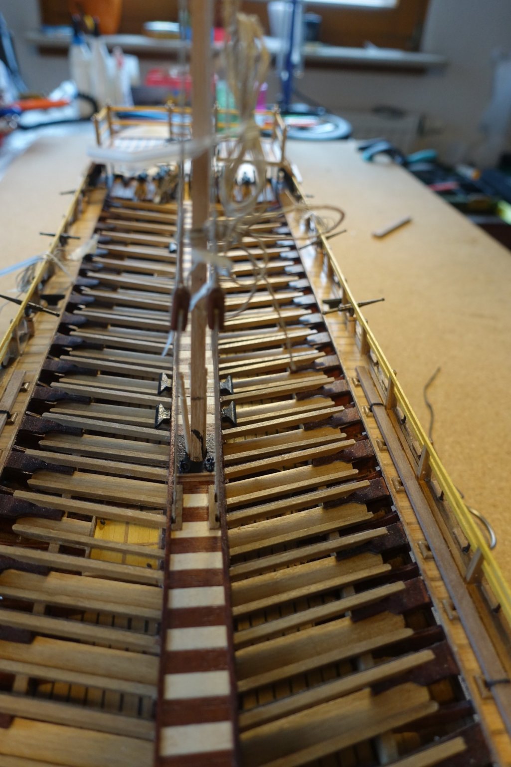
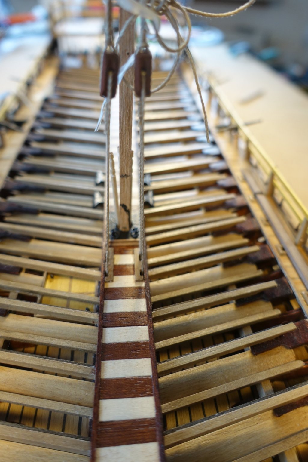
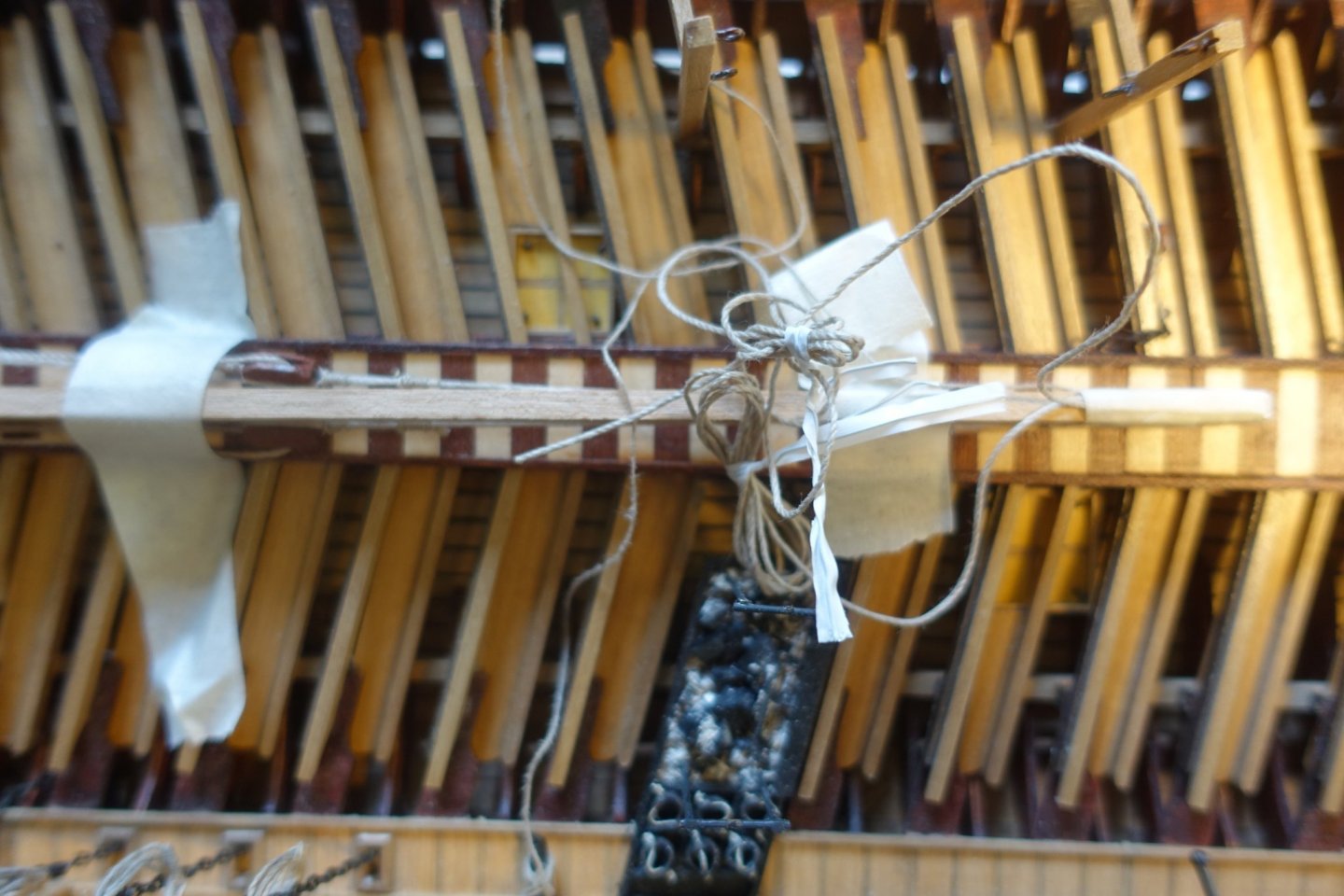
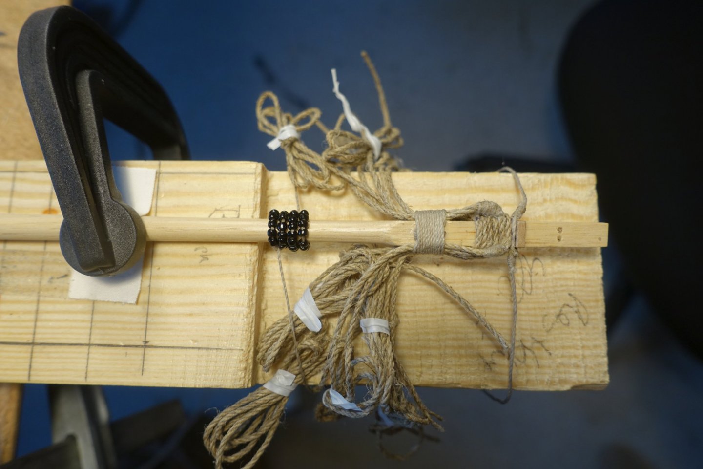
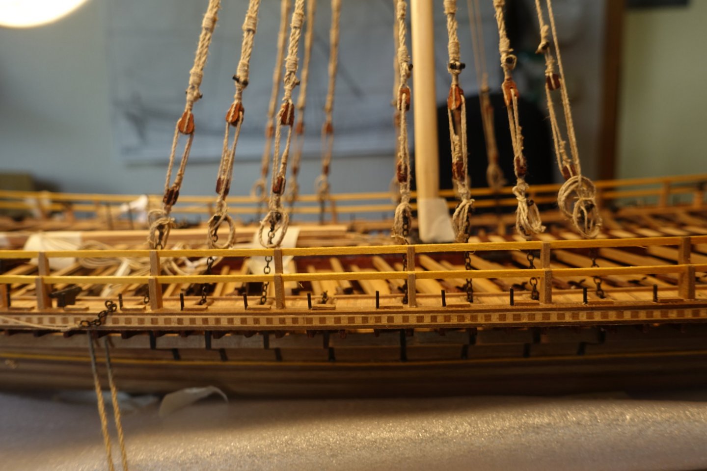
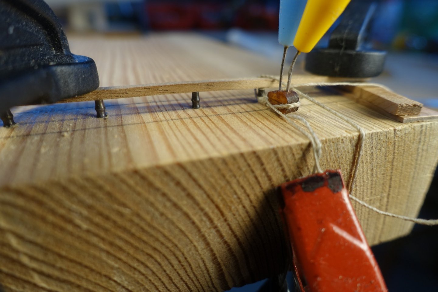
I have installed the midway planks. Just behind the main mast, the lines of the haleyard of the main yard run through the planks. To place the holes in the midway planks correctly, I mounted a preliminary main mast and attached the lines of the haleyard to it. I also installed most of the lines later needed for handling the yards (tackles etc.). I thought it would be difficult to attach them when masts and shrouds are added. The lines were pulled through bee wax (to get a slight stiffness) and carefully flamed (to remove the “hairs”). Next step will be preparing the masts.


- 112 replies
-
- 5
-
-
- corel
- reale de france
- (and 1 more)
-
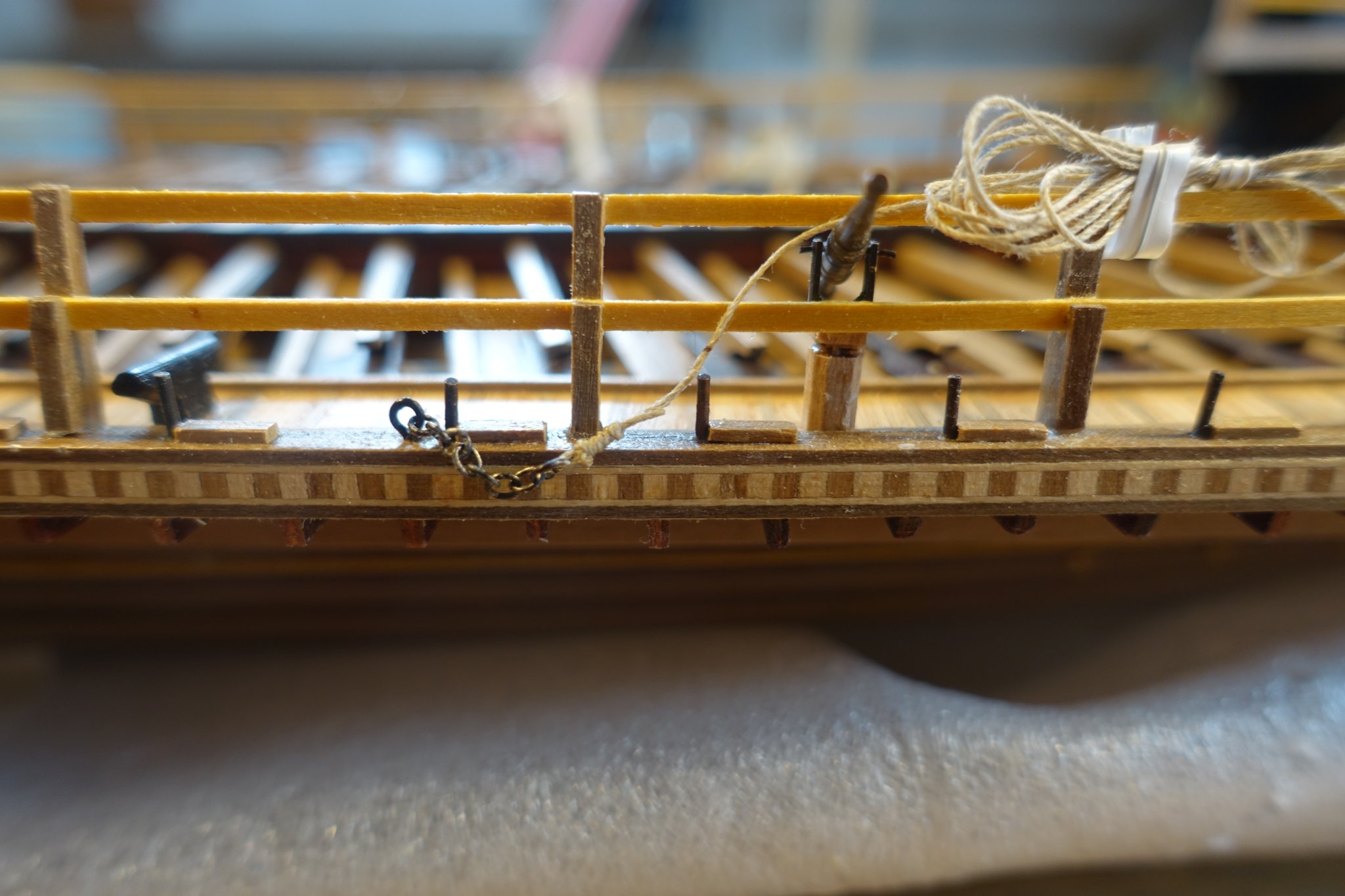
Hi Frank, good idea to simulate the holding wire of the davits which is surely more realistic. I am also in the process of attaching the cleats and rigging lines. It will be probably more difficult when masts and shrouds are installed. Clark
- 510 replies
-
- 1
-
-
- reale de france
- corel
- (and 1 more)
-
Frank, glad you are prooceeding. I am not sure if you are running into the same problem as I did. Are you aware that there should be enough space between the swivel guns and the lower railing? Clark
-
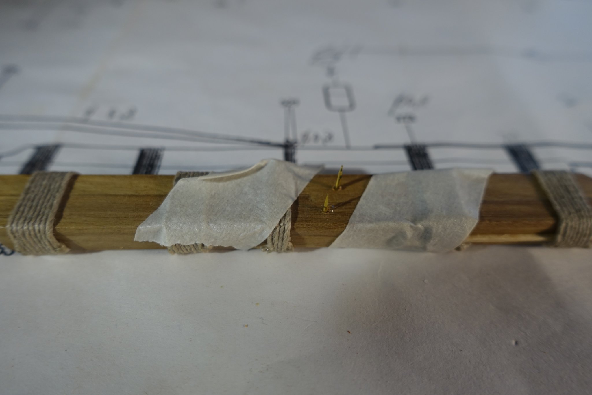
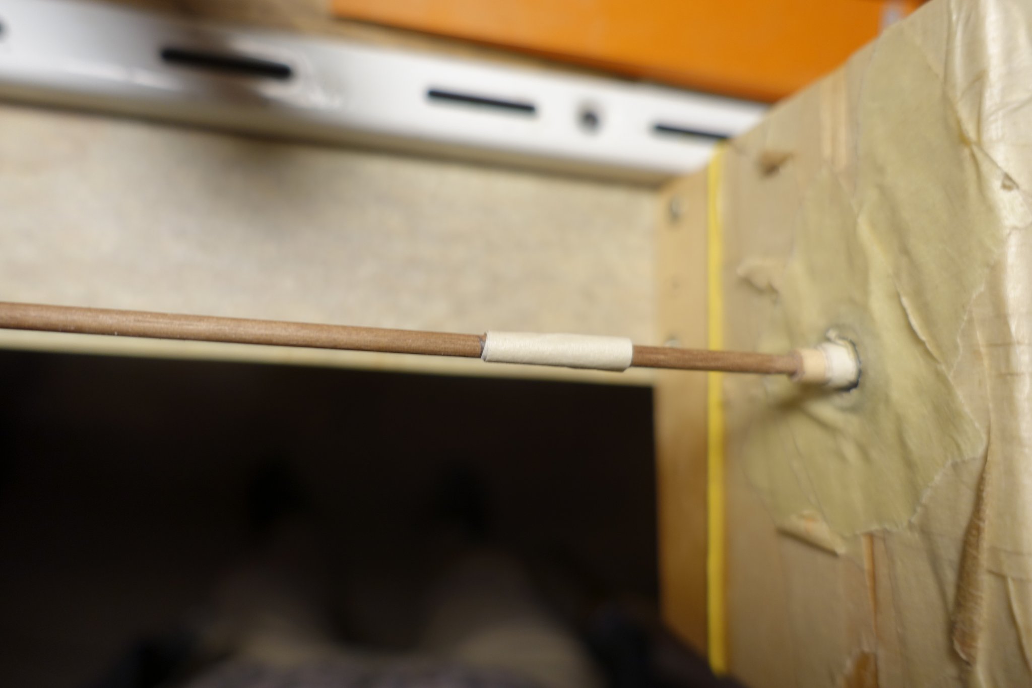
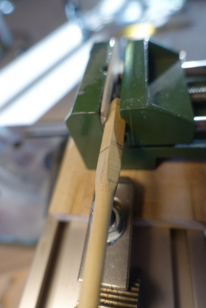
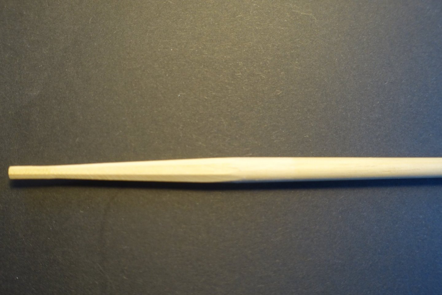
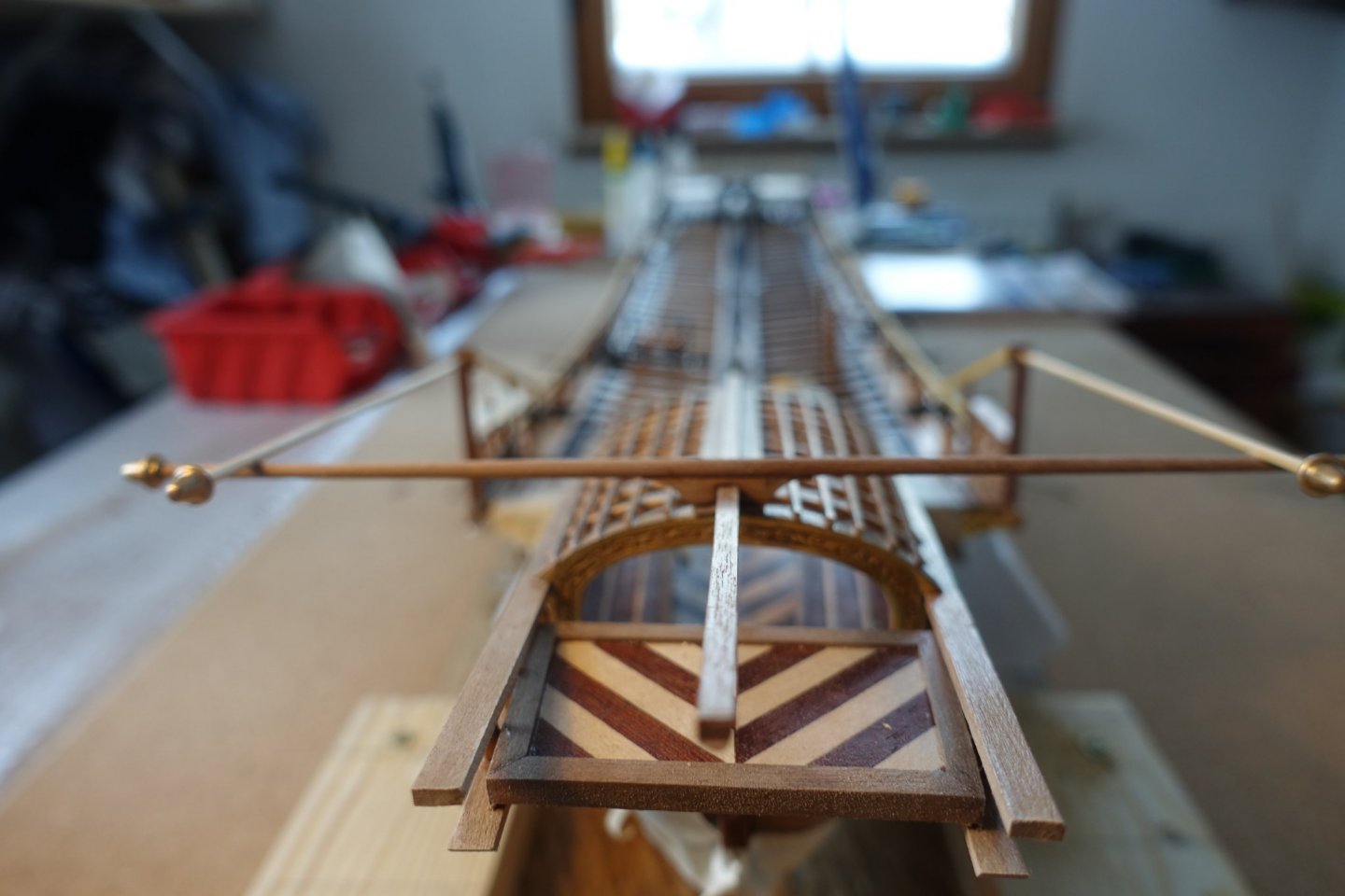
After mounting the swivel guns, I adapted the spars later necessary to support the stern drape (I still hesitate whether to put on the drape or not, it will cover a lot). The cross bar was made out of a tapered 3mm spar. I used my old “lathe” made out of a drill machine on one side and a ball bearing on the other side. Opening of the ball bearing was minimized by a small spar. It is not very sophisticated but I have used it very often before to taper masts and yards. It worked. Tapered bar was glued on a carved support put on the arch construction.


- 112 replies
-
- 2
-
-
- corel
- reale de france
- (and 1 more)
-
Just browsed through the offers. There are some remarks that the cuts are not very precise. I would also be interested in any answers. Is it possible to design and print ornaments on thin (~0.5mm) wooden planks?
-
Pinnace kit arrived yesterday (ordered 10 d ago). Looks perfect. Recommendation to all not only to those who like details. Clark
-
Hi Frank, I have sent the manual to Ogun already. Clark
- 510 replies
-
- 1
-
-
- reale de france
- corel
- (and 1 more)
-
May be I can help. Both is with me. Please send me a short note. However, manual description does not help a lot. Better to follow the blogs. Clark