Clark
-
Posts
310 -
Joined
-
Last visited
Content Type
Profiles
Forums
Gallery
Events
Everything posted by Clark
-
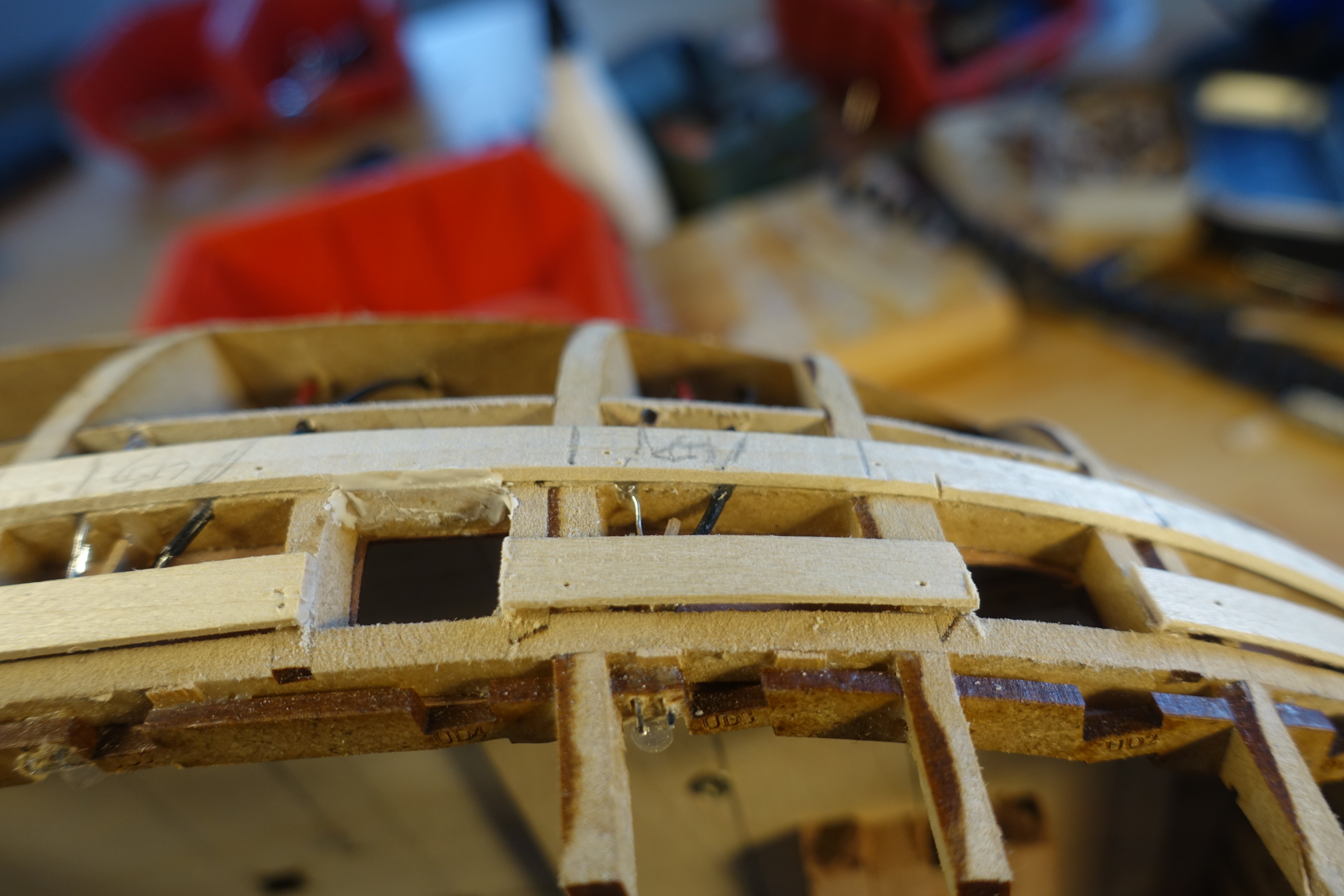
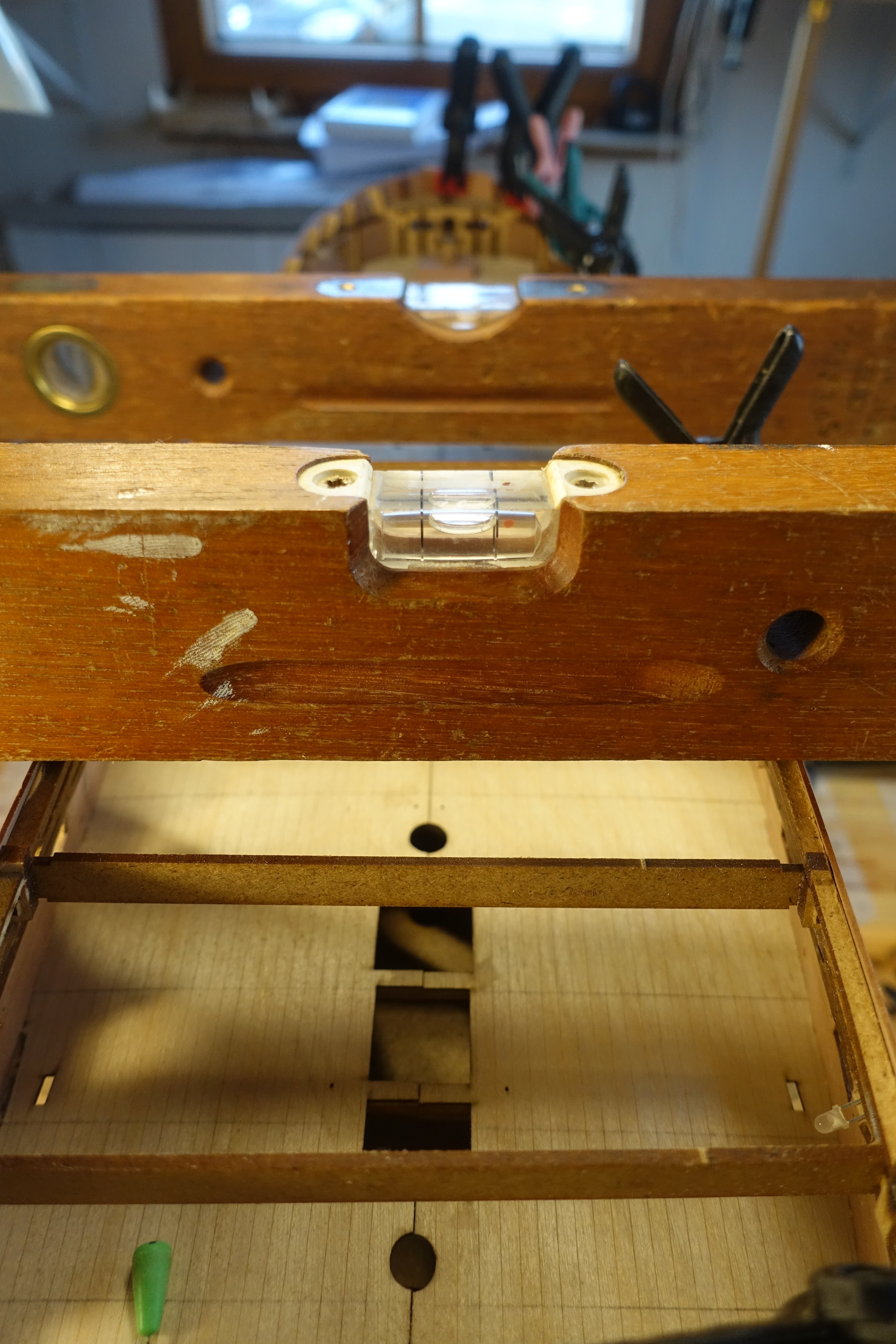
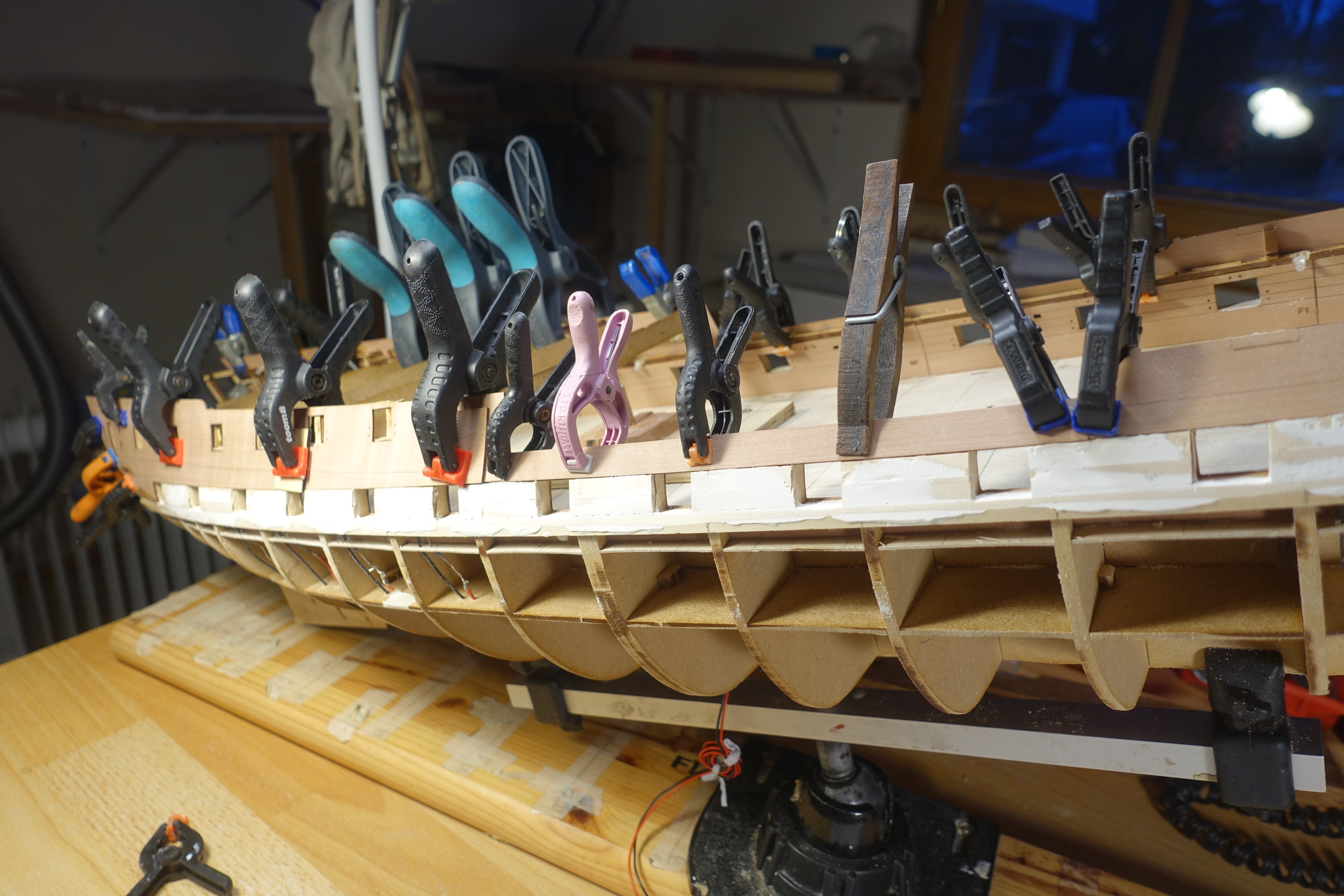
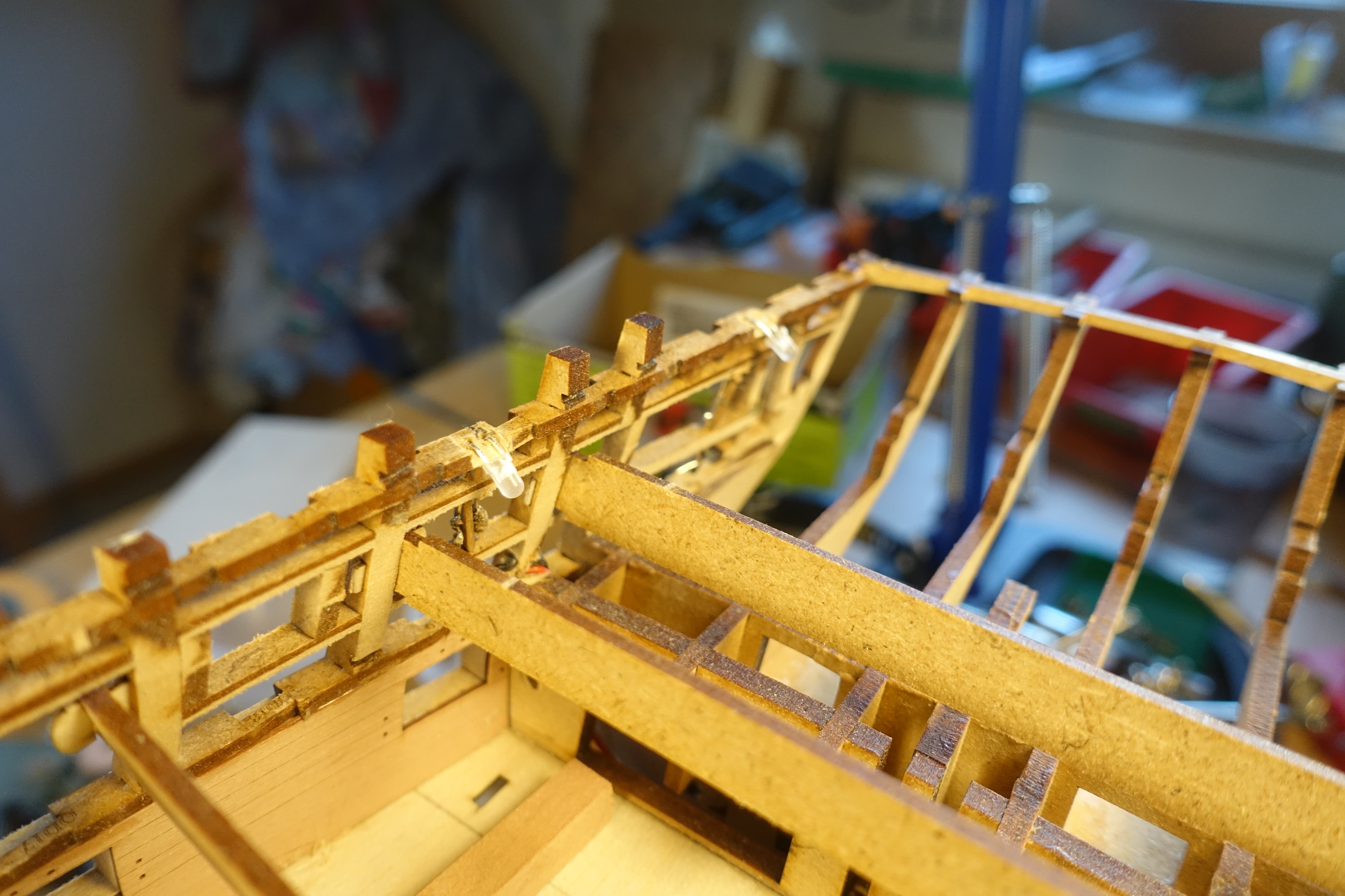
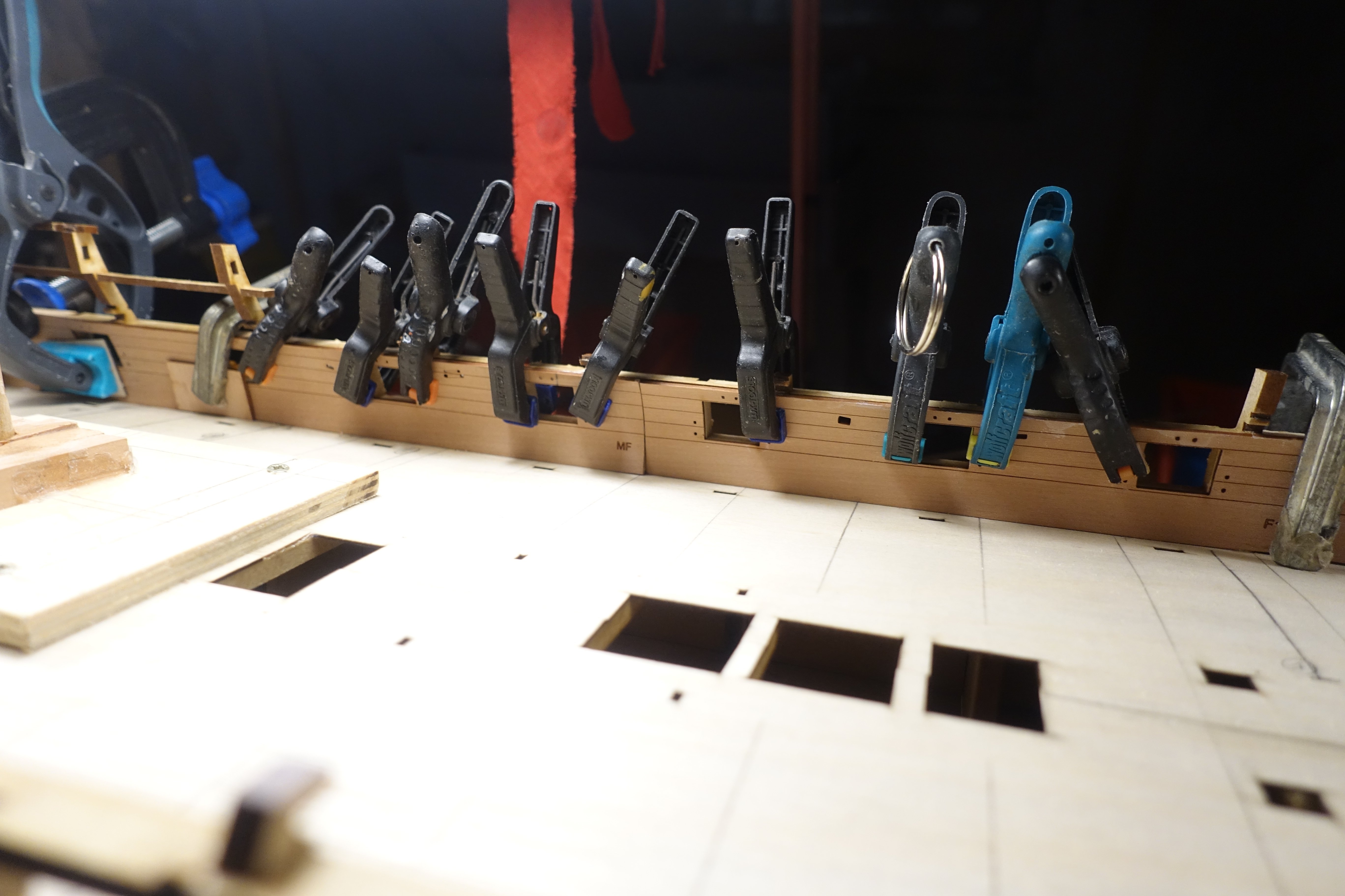
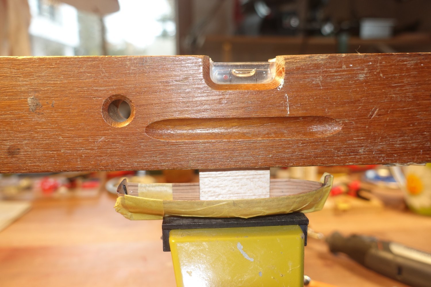
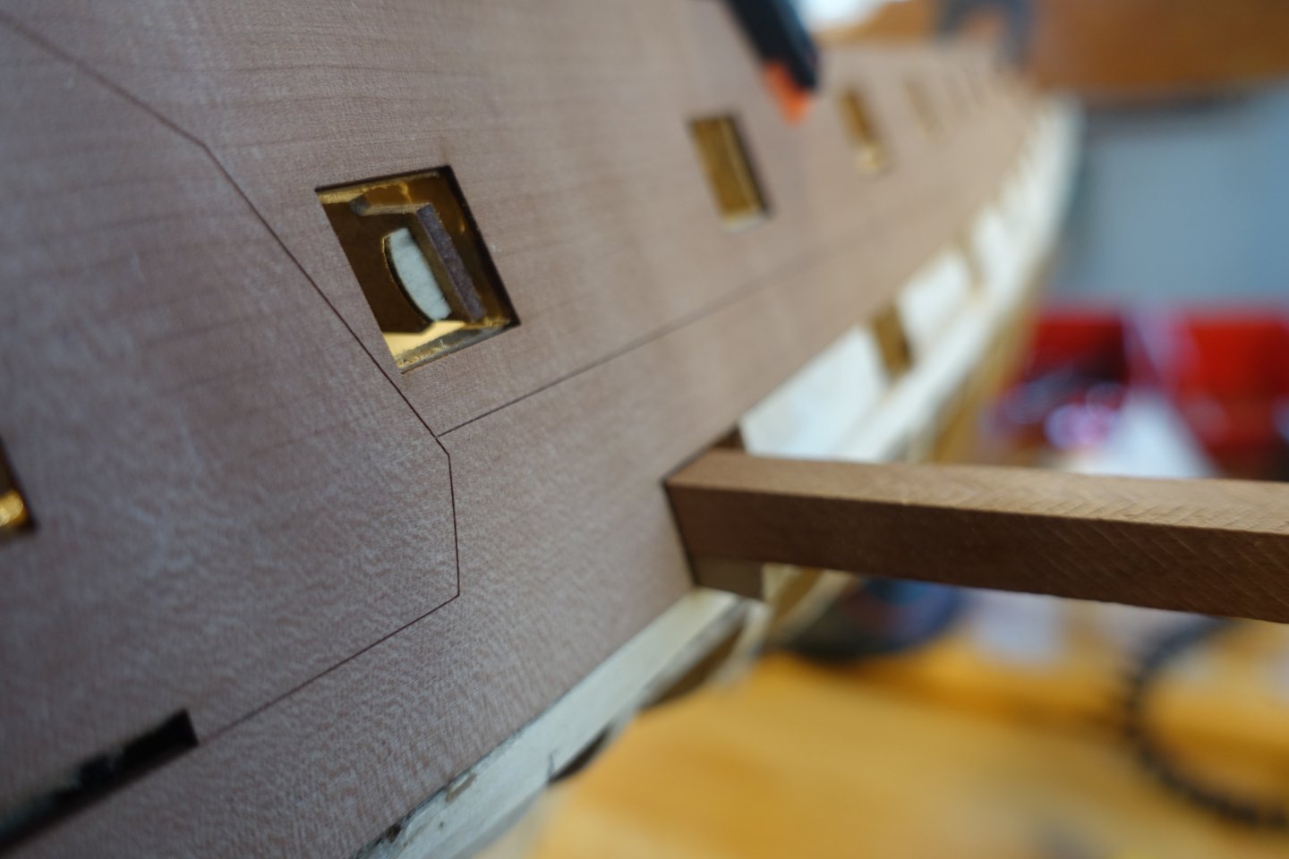
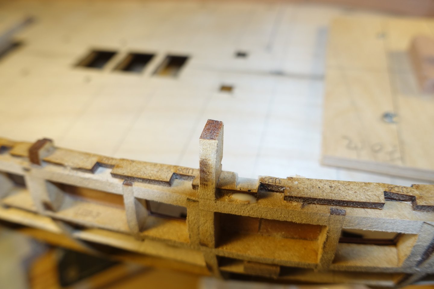
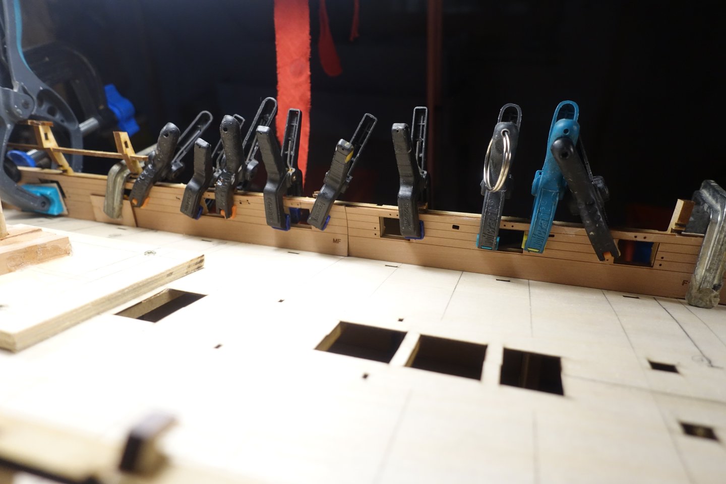
Next, the outer bulwarks have to be attached, along with the strips that form the lower boundary of the gun ports. The main strip for the lower edge of the gun ports was easy to lay. For the stern area, I hot-bent a second strip and then laid it with the front part butted up against it. However, I am not completely satisfied with the way the strip runs in the stern area, so I will have to make some improvements. In the middle area, small gaps of approx. 0.1 to 0.2 mm in size were visible between the edge of the gun ports and the border moulding. I filled this with liquefied putty. The gun ports will have to be sanded flat later anyway. That's the nice thing about working with wood. You can fix anything somehow. A strip had to be glued over the gun ports. There was a gap of about 1 mm between this and the lower strip. This was also filled with diluted putty, avoiding the area of the gun ports. To fix and align the aft bulwarks, I pushed a square rod through the last gun port flush to the aft and upward. With the help of spirit levels, the port and starboard bulwarks were levelled against each other. Clamping the bulwarks after gluing them proved somewhat difficult, since the clamps should not touch the LED under any circumstances, so that essentially only the area of the gun deck gun ports was left for the clamps. The bulwarks in the bow area are a good match. What I don't like at all is the transition at the stern. I'll probably have to add a little more putty here over the next few days.


-
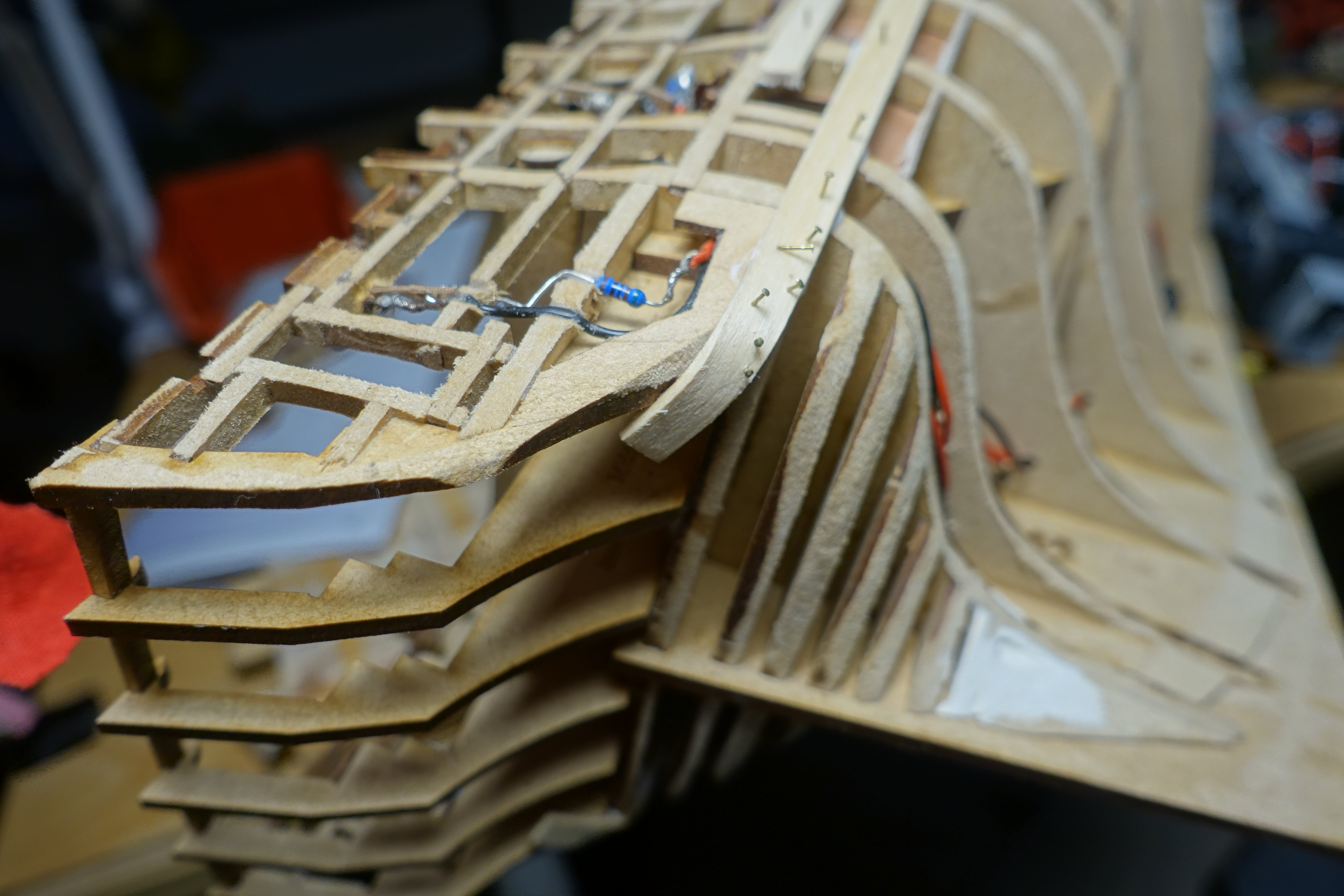
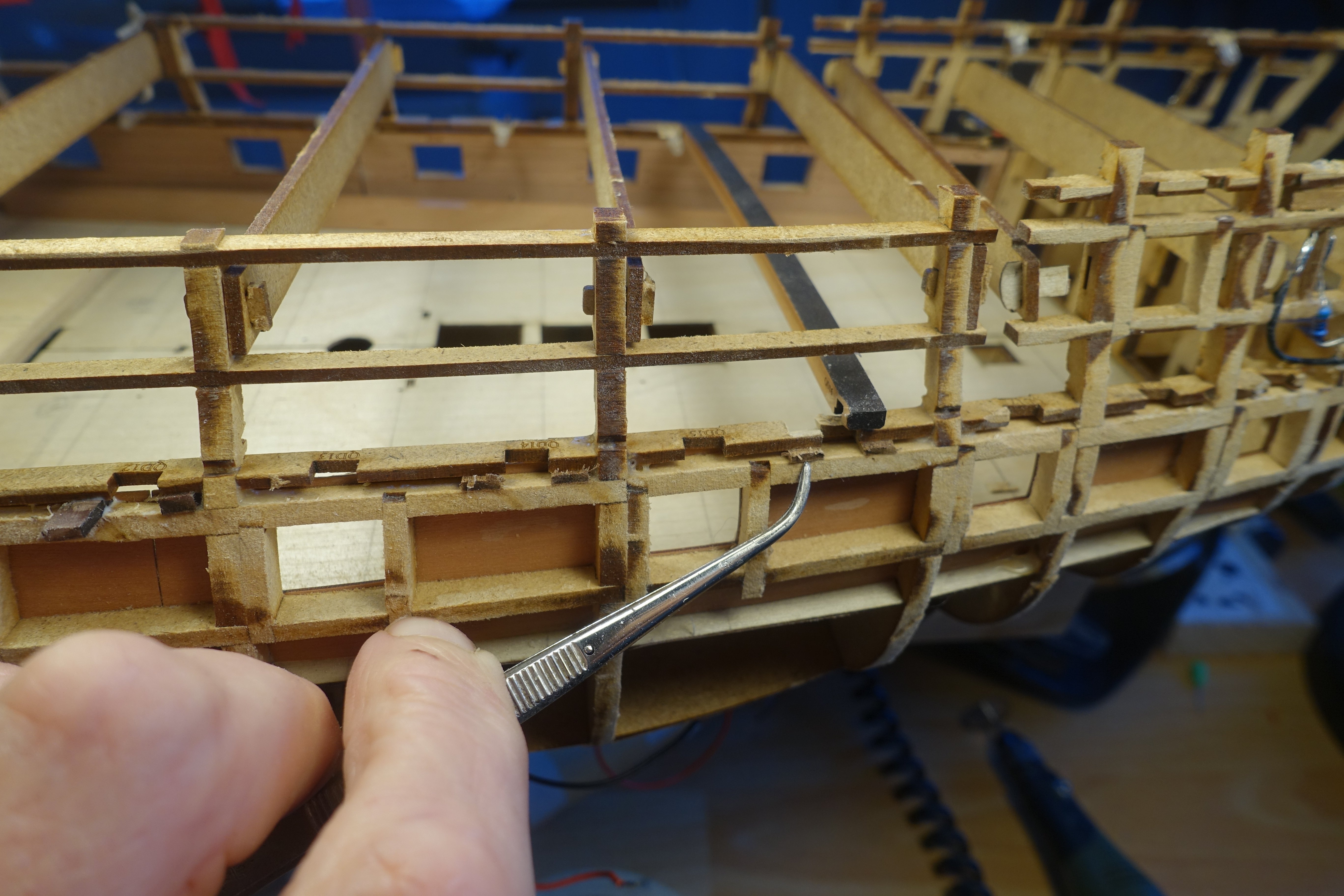
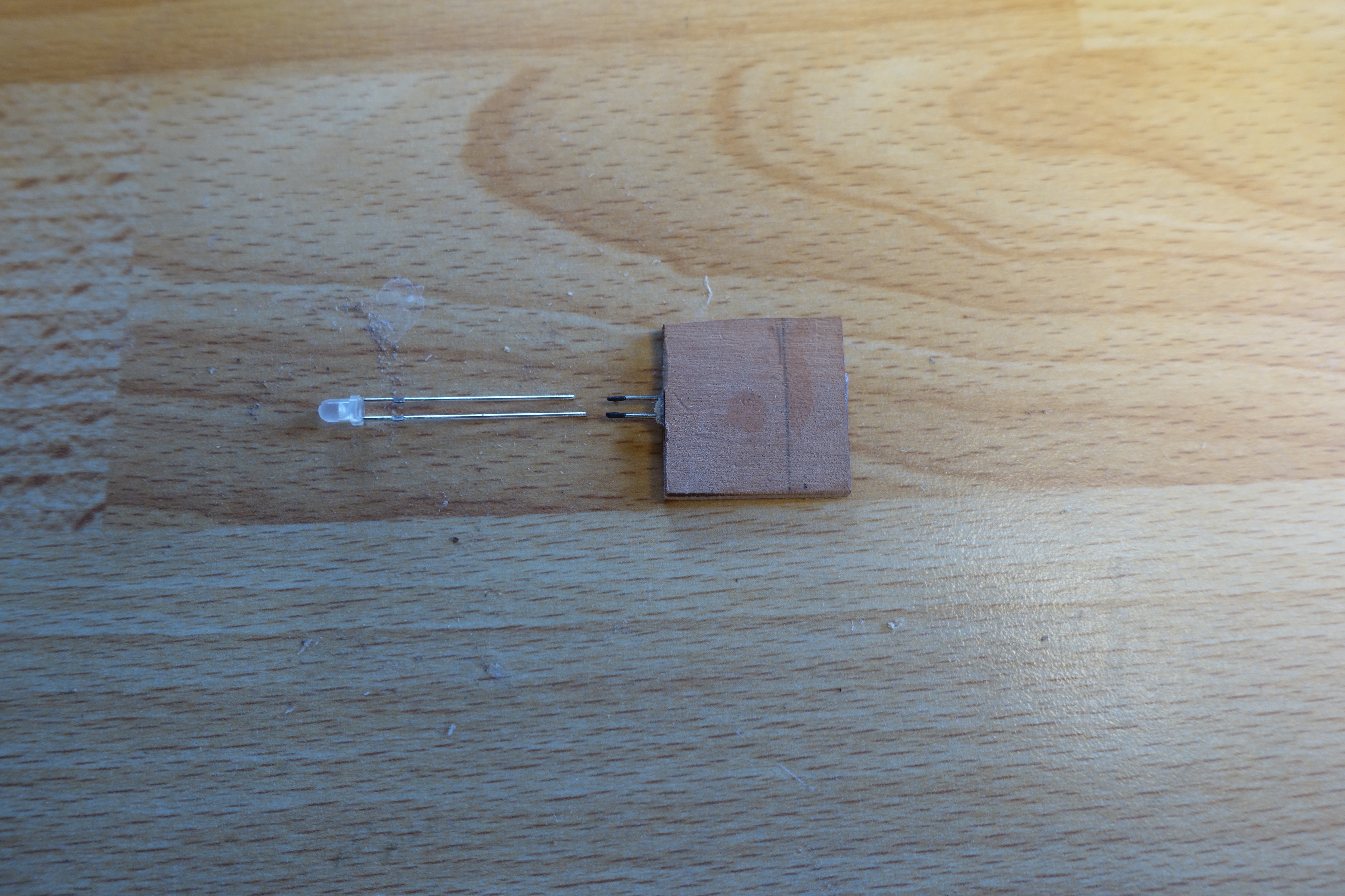
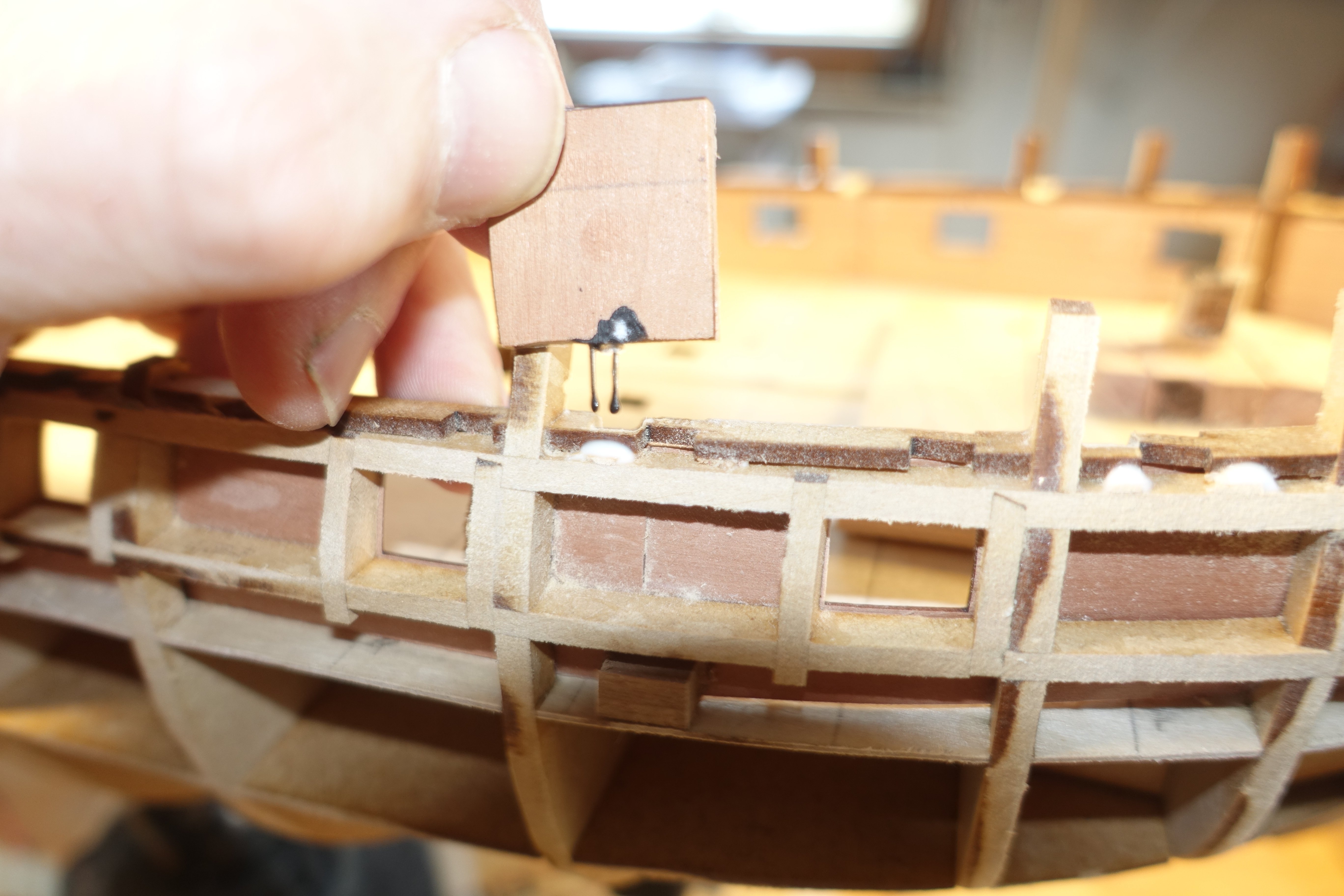
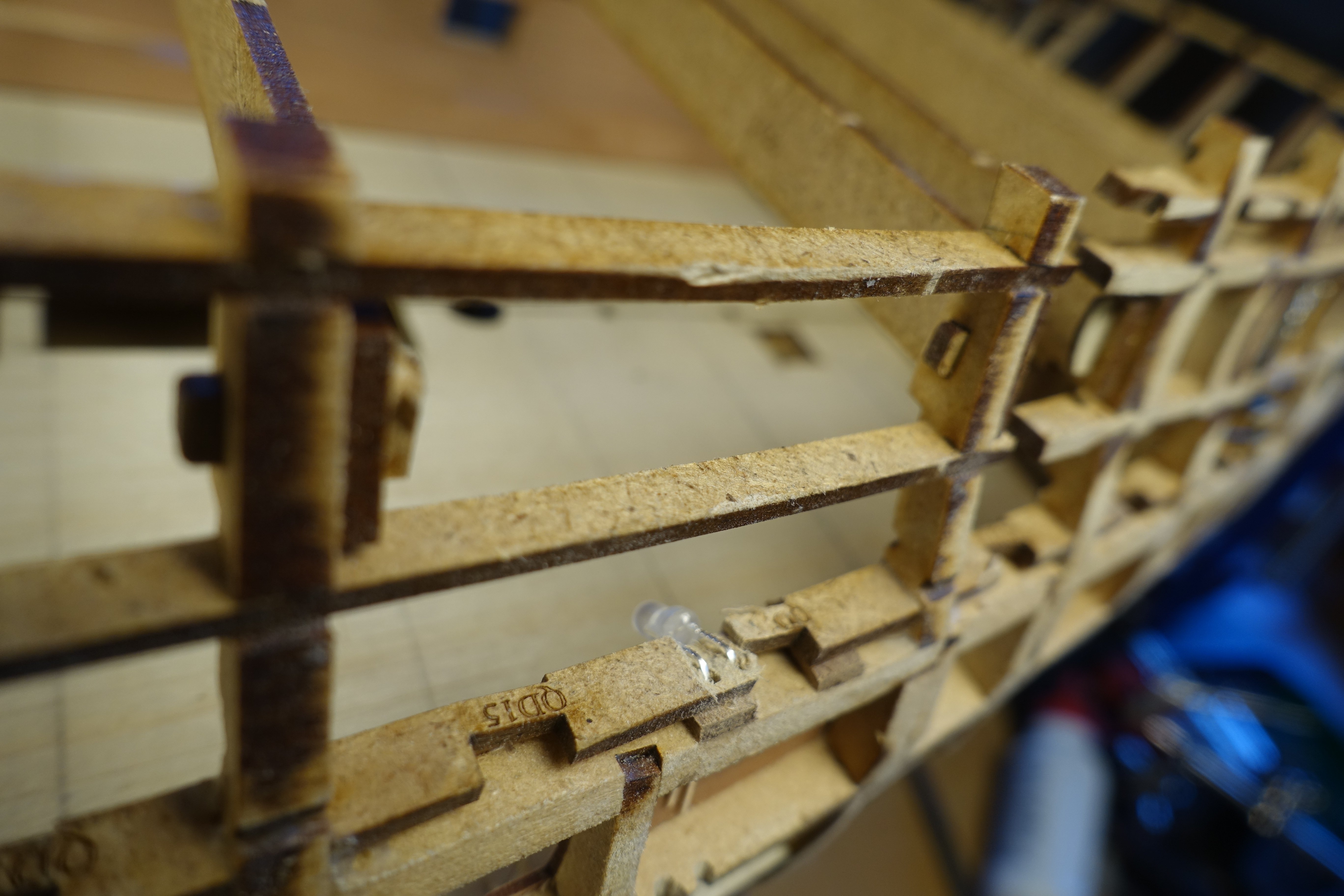
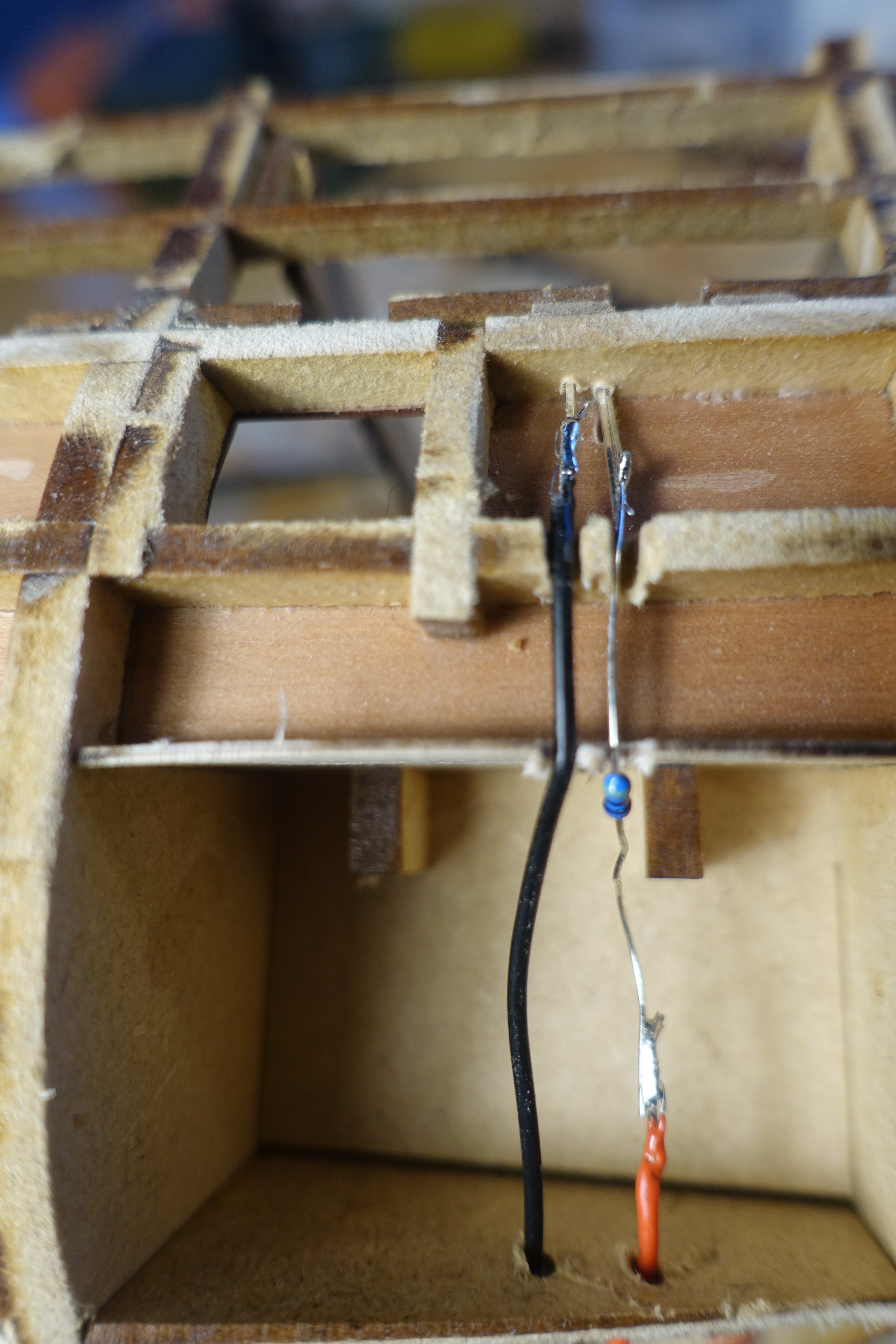
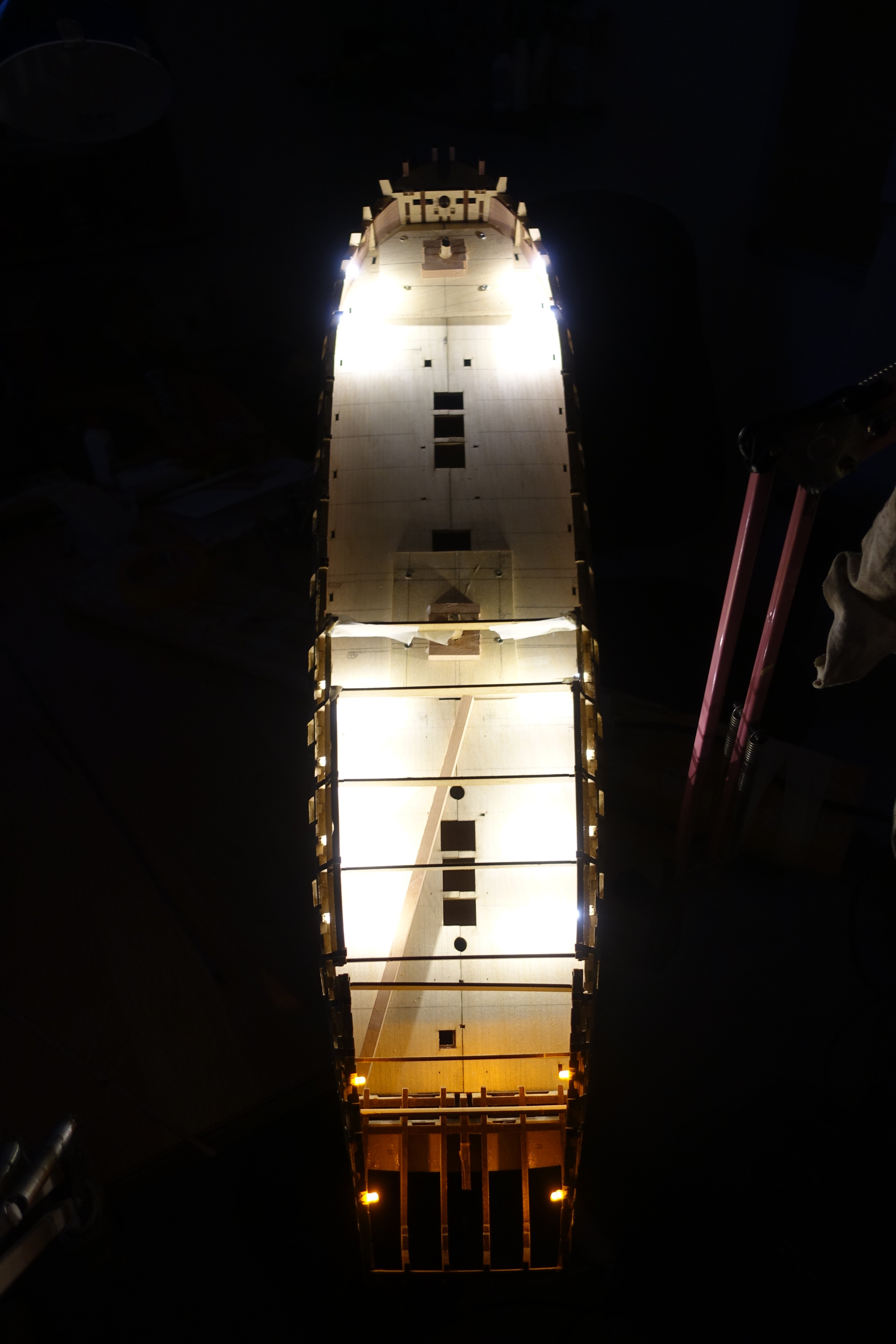
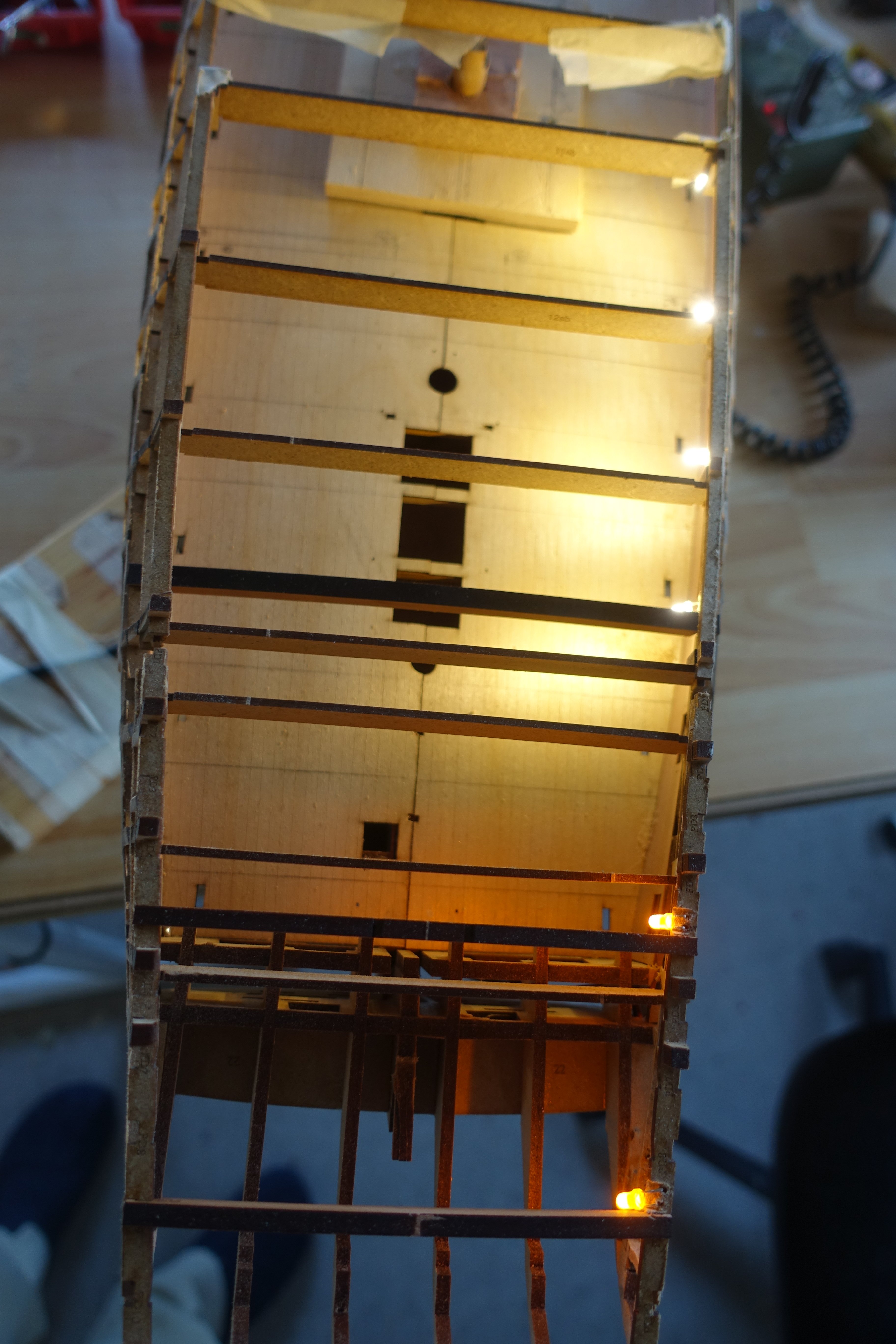
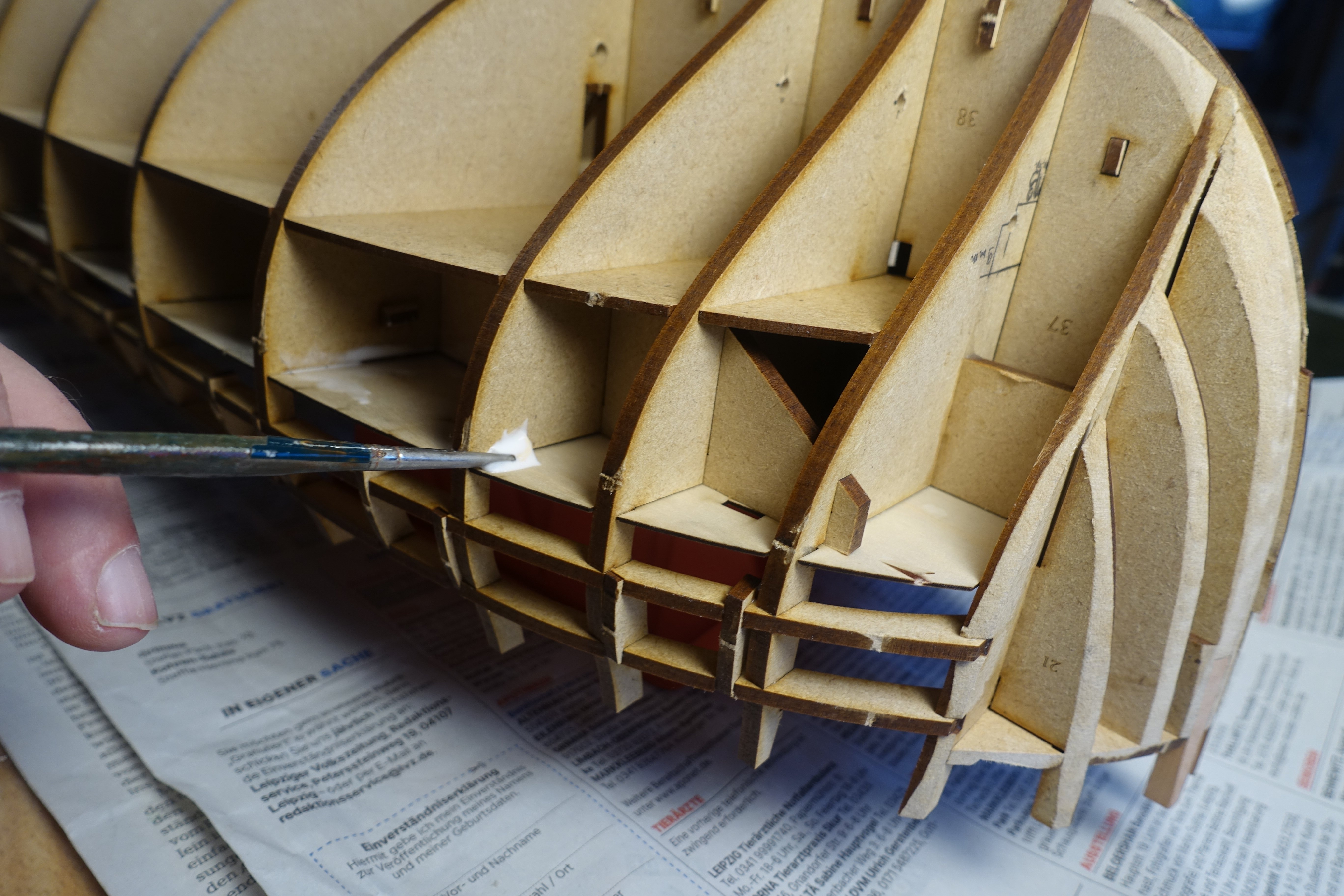
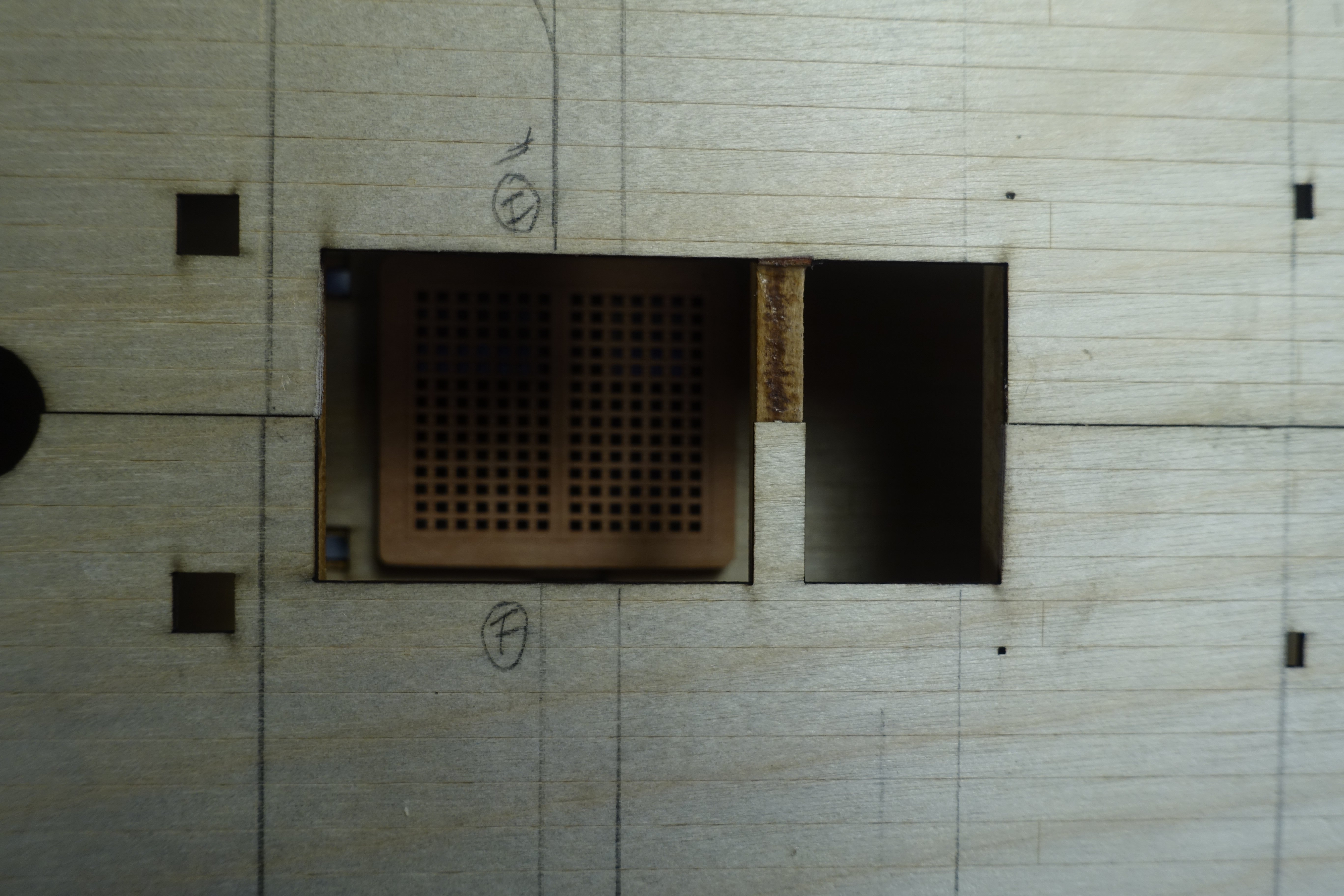
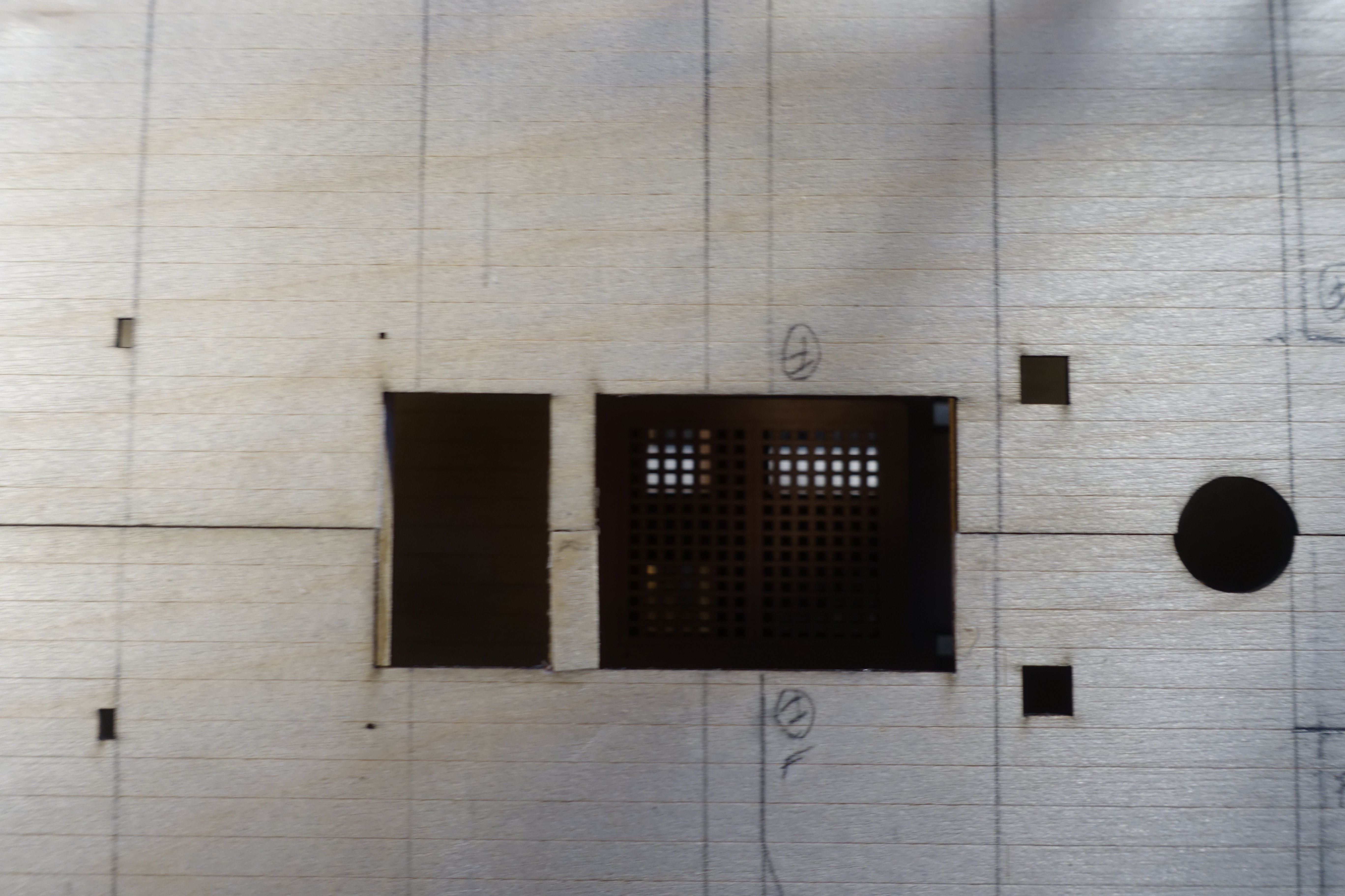
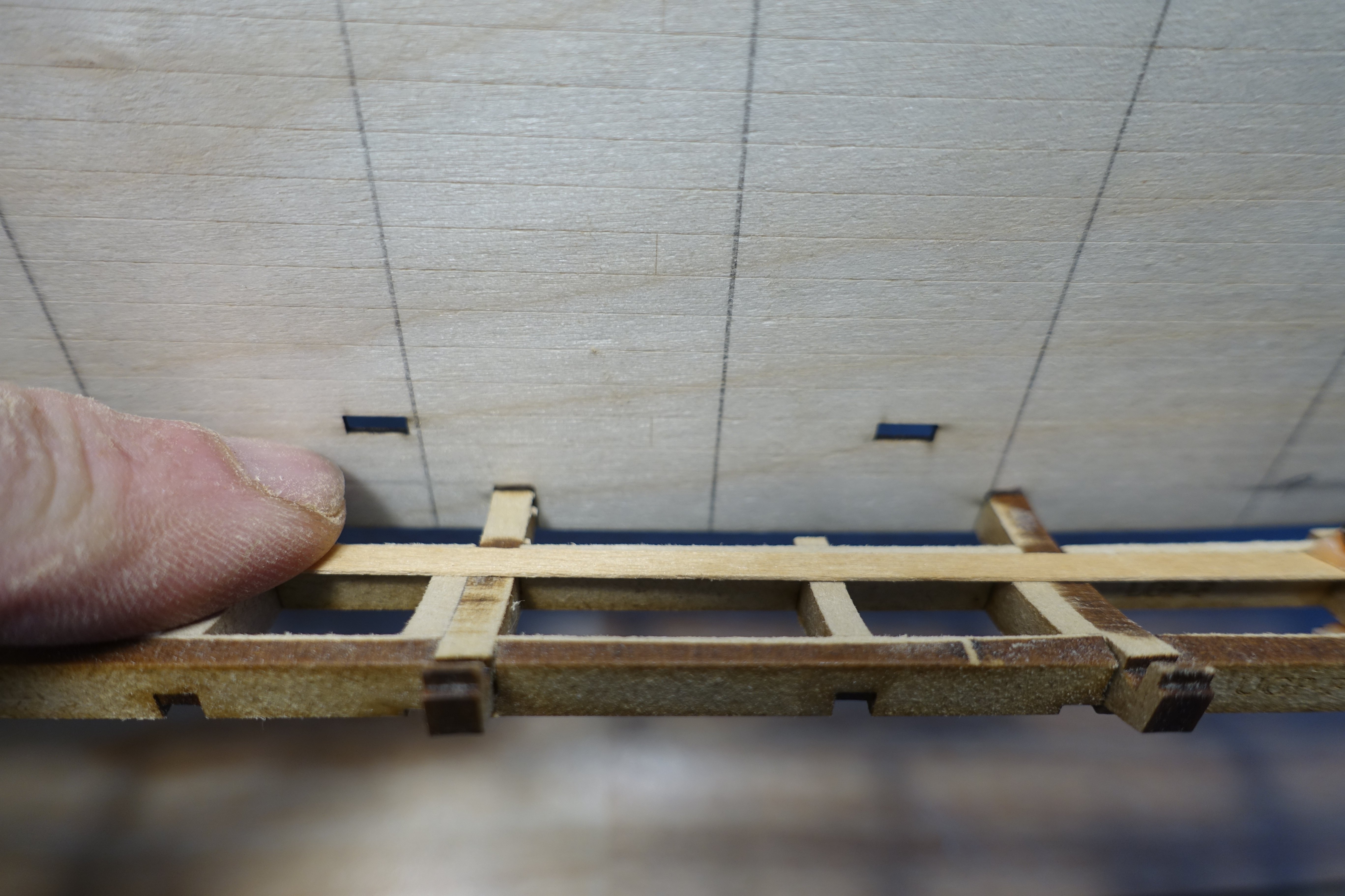
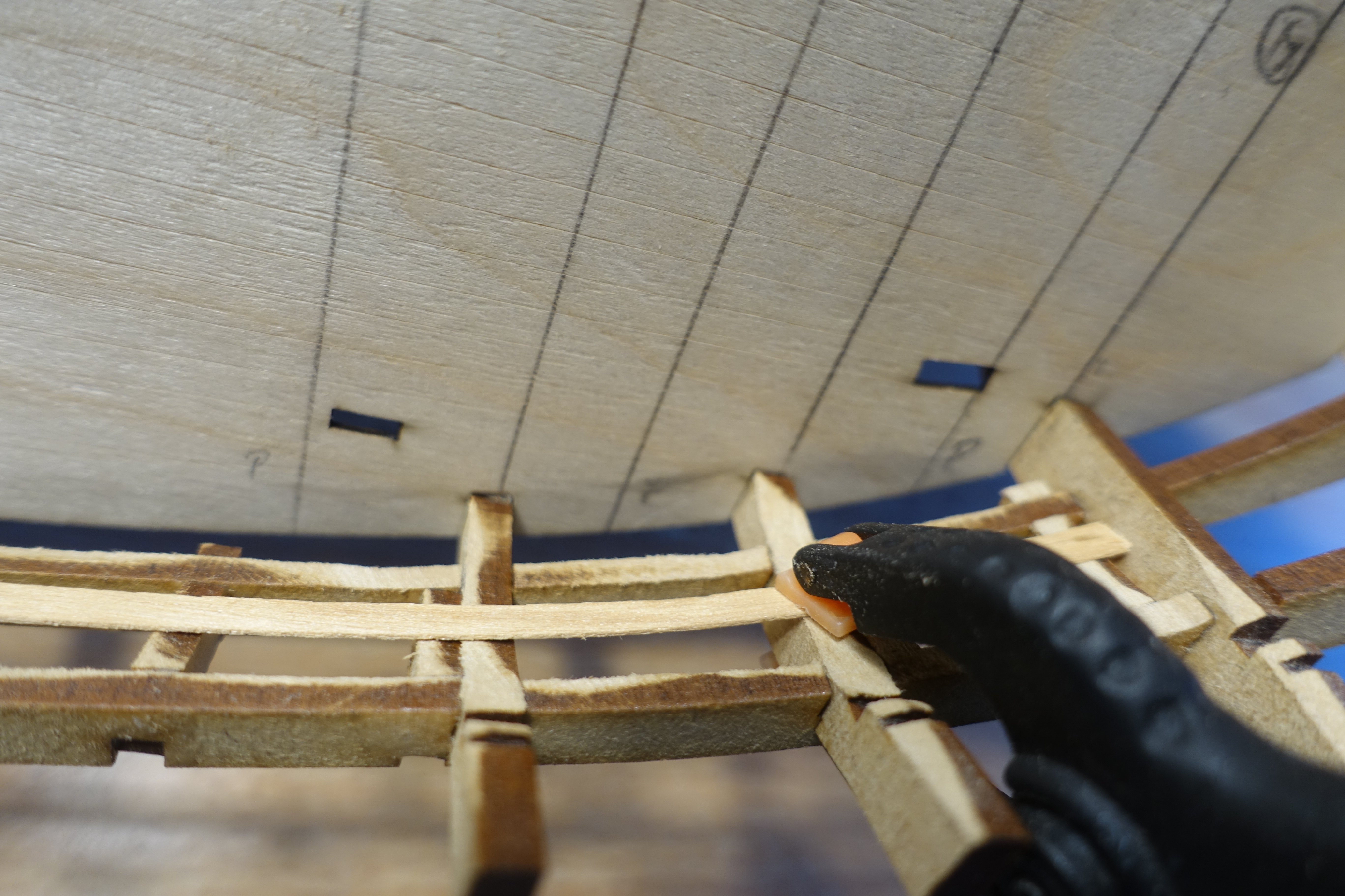
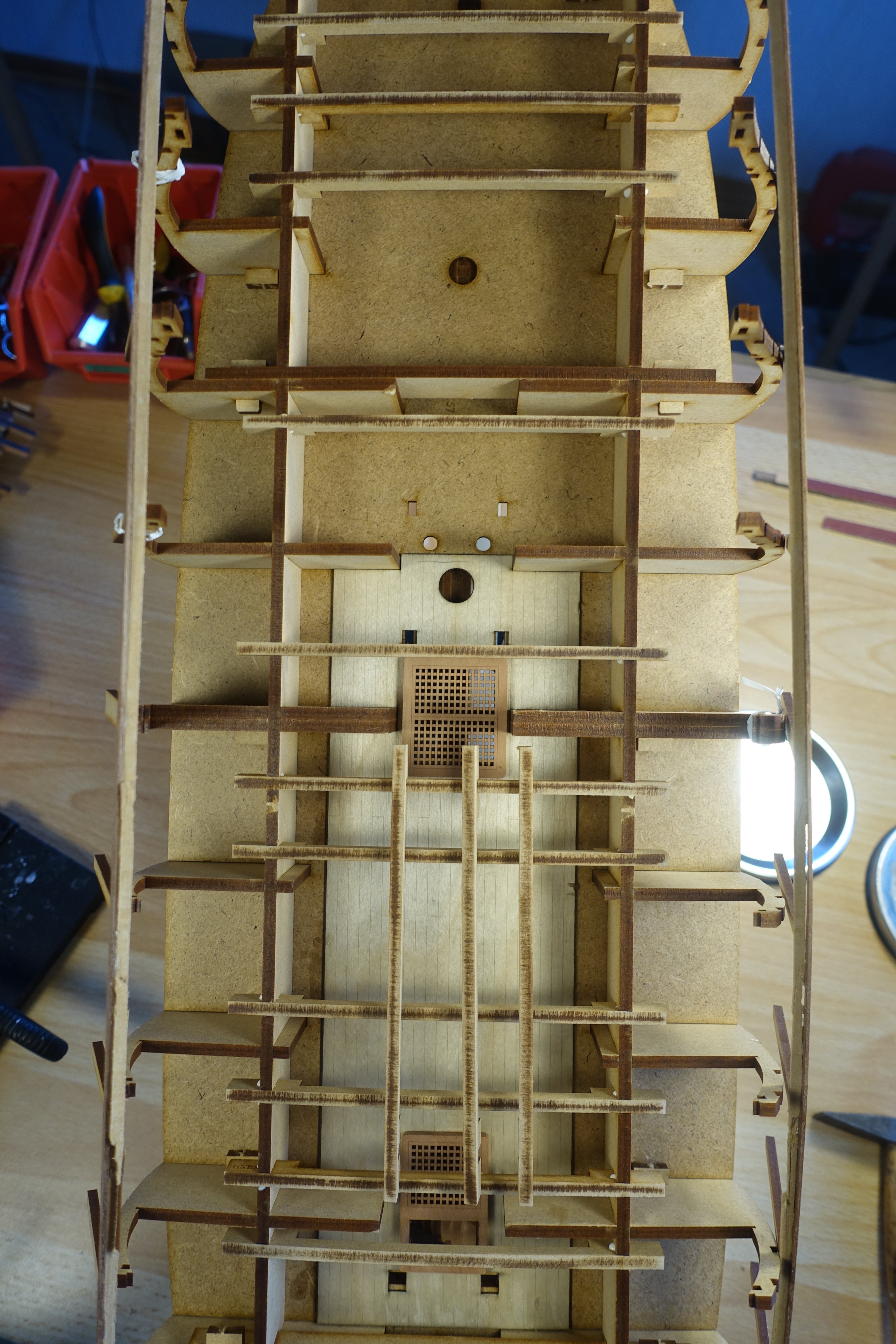
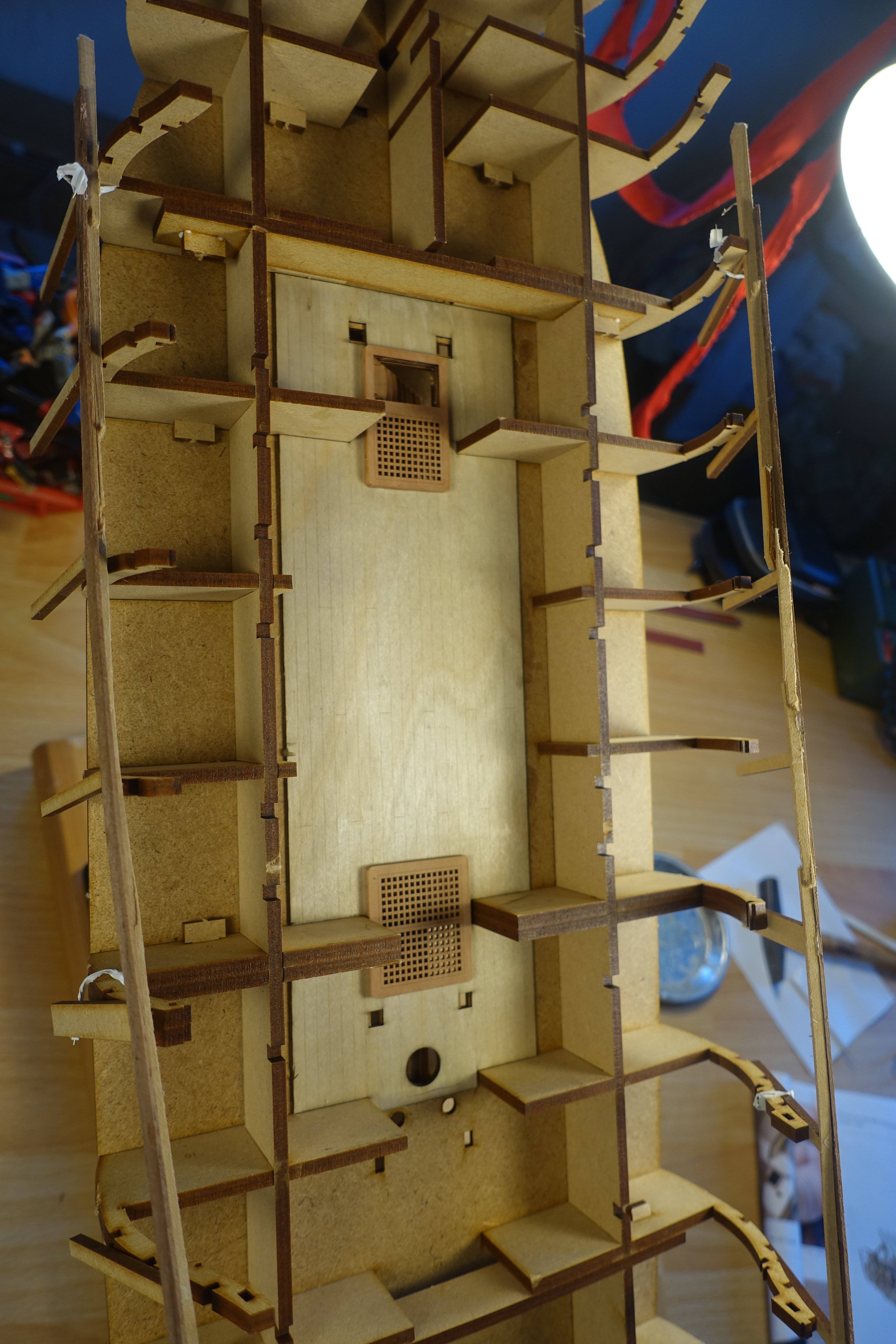
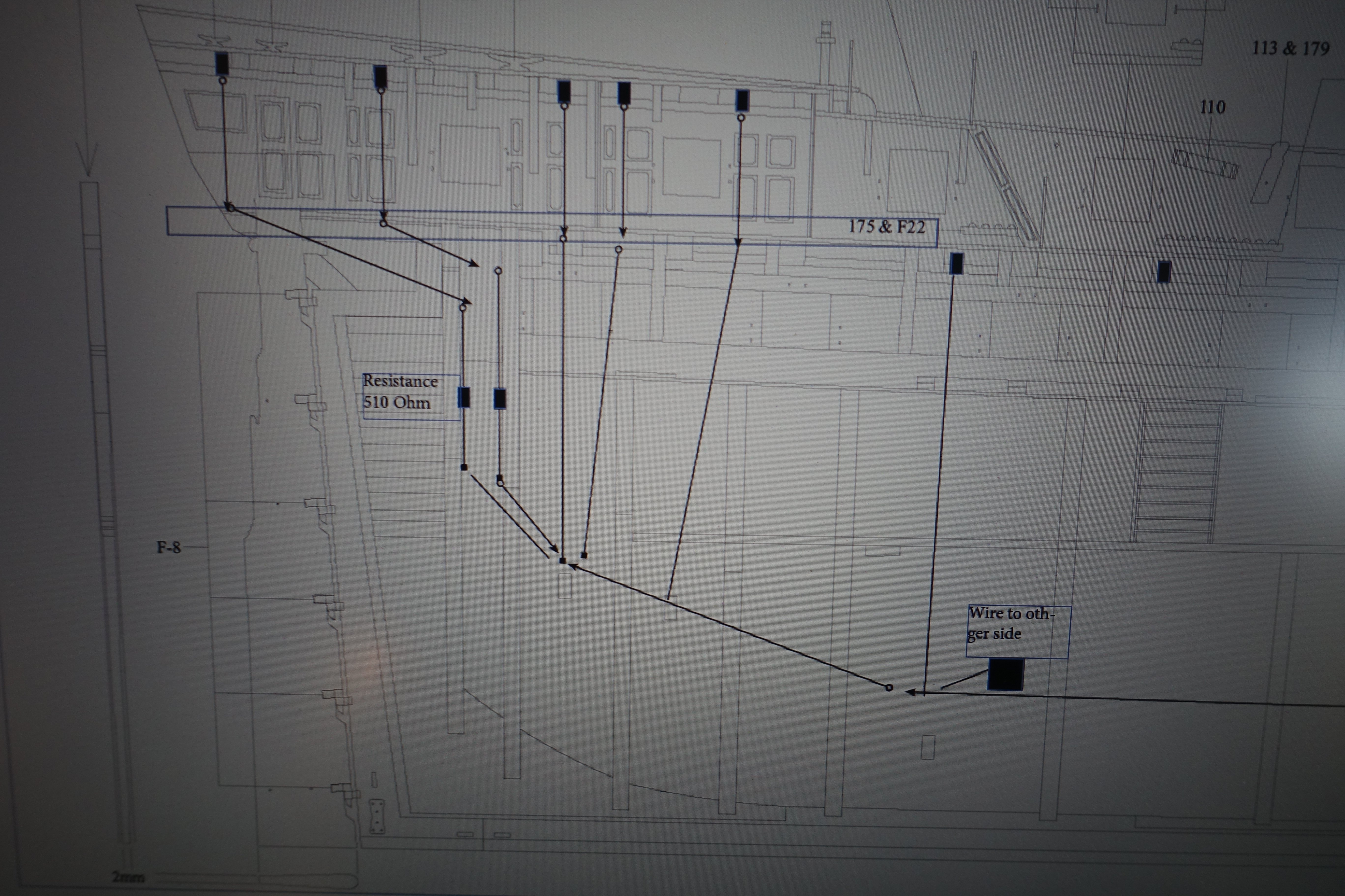
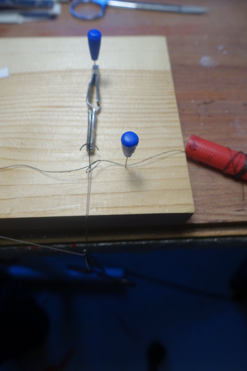
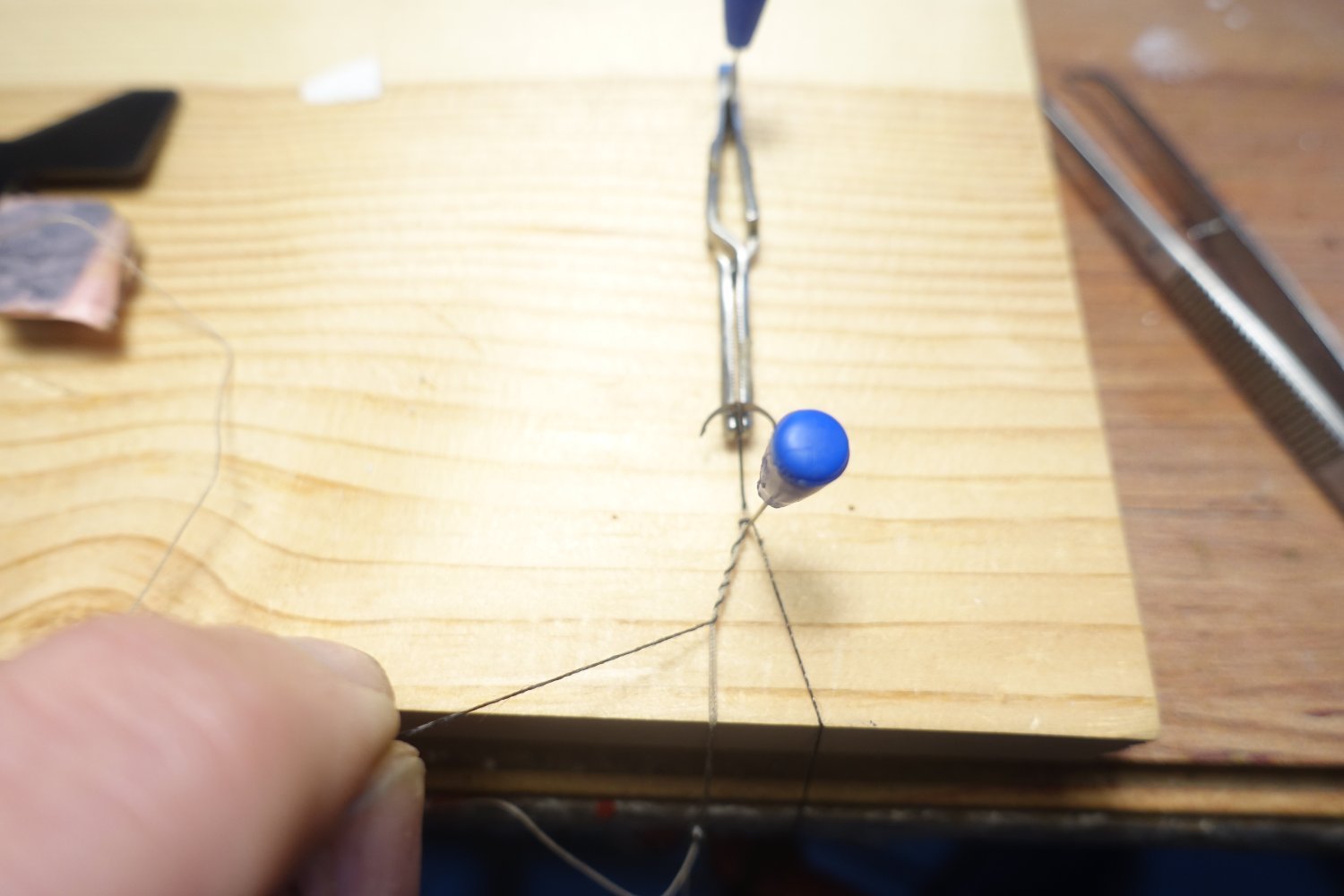
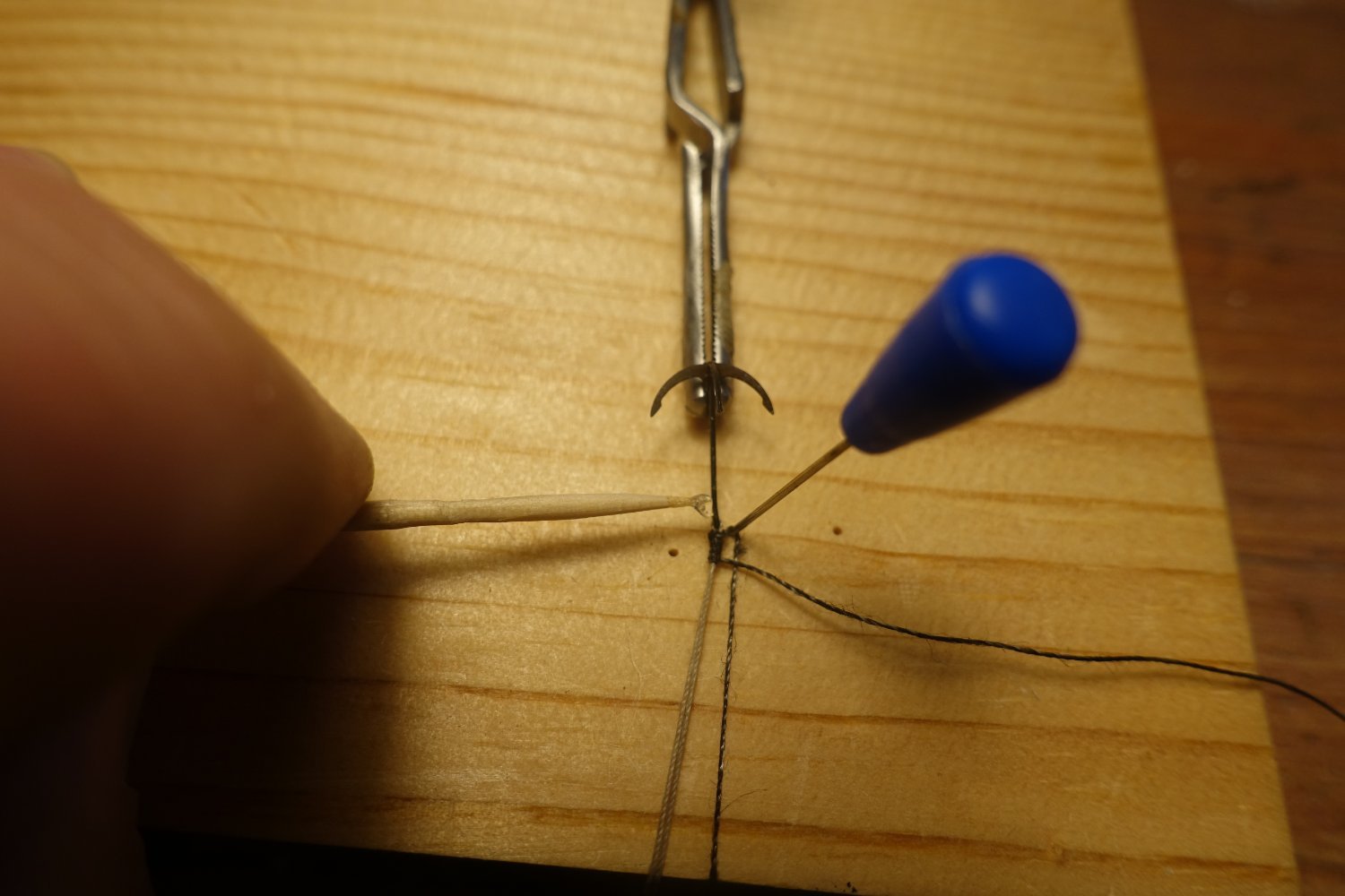
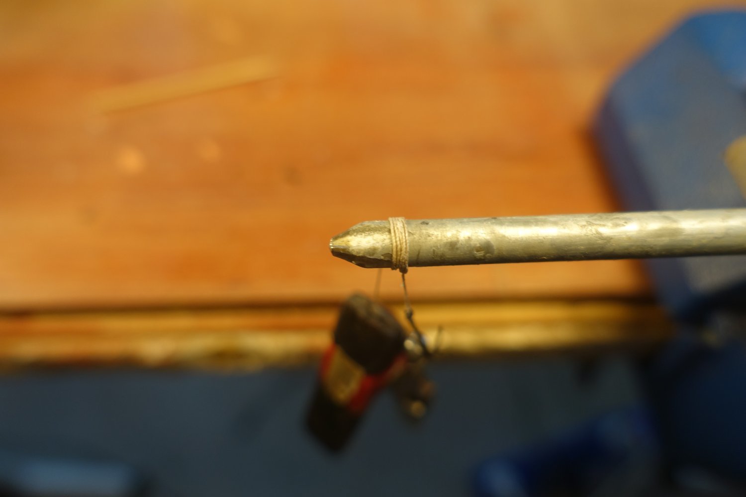
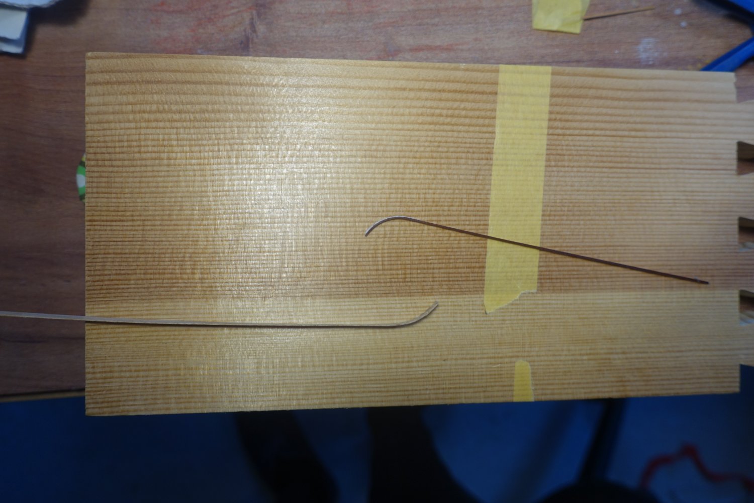
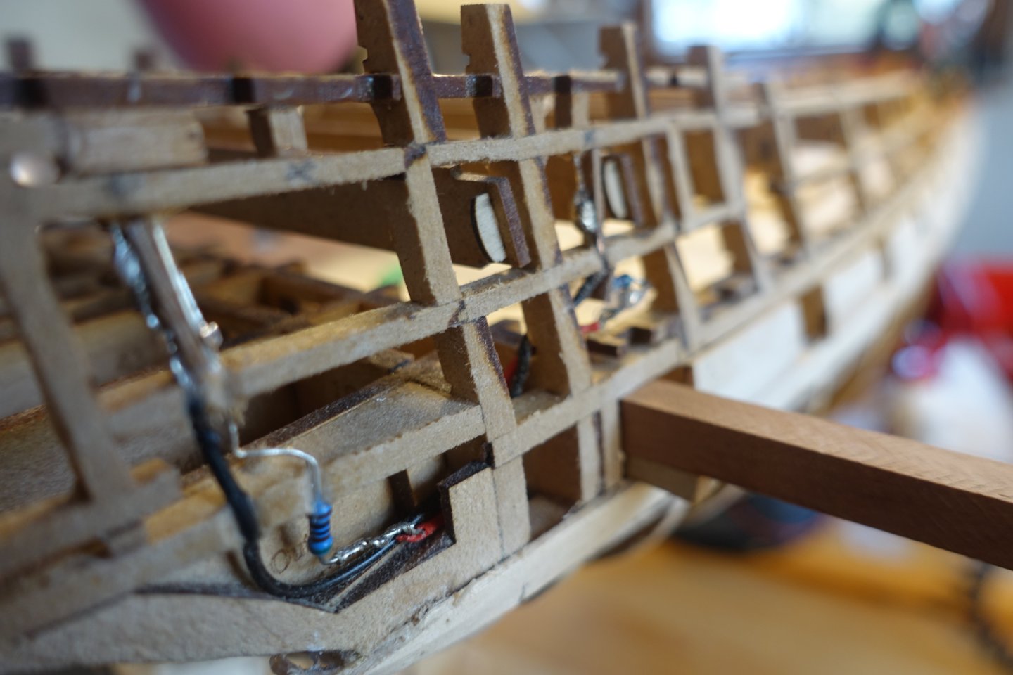
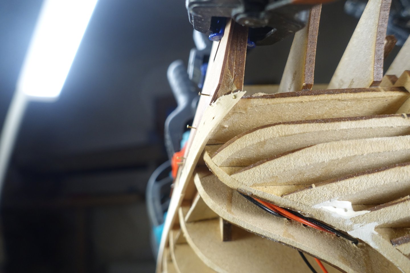
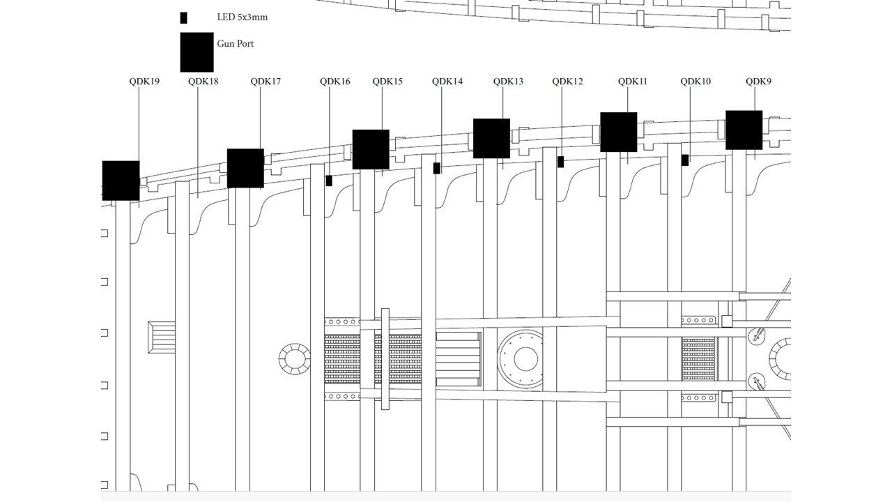
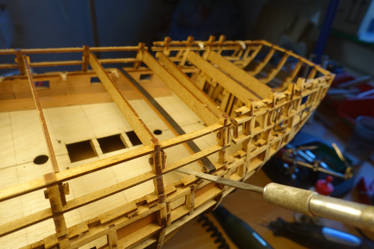
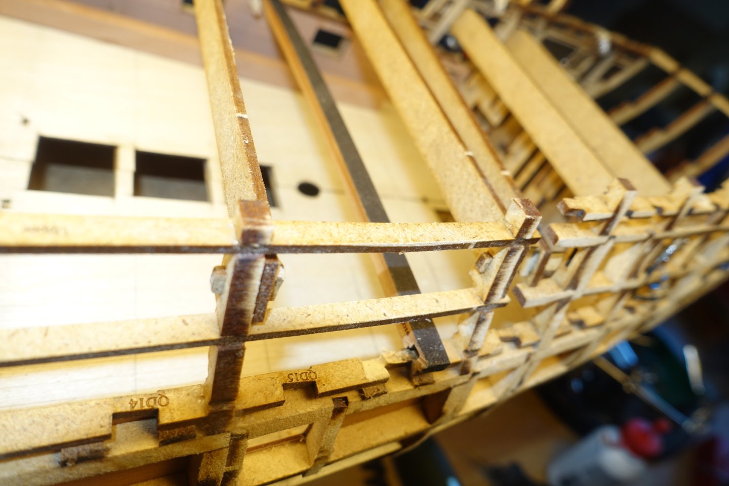
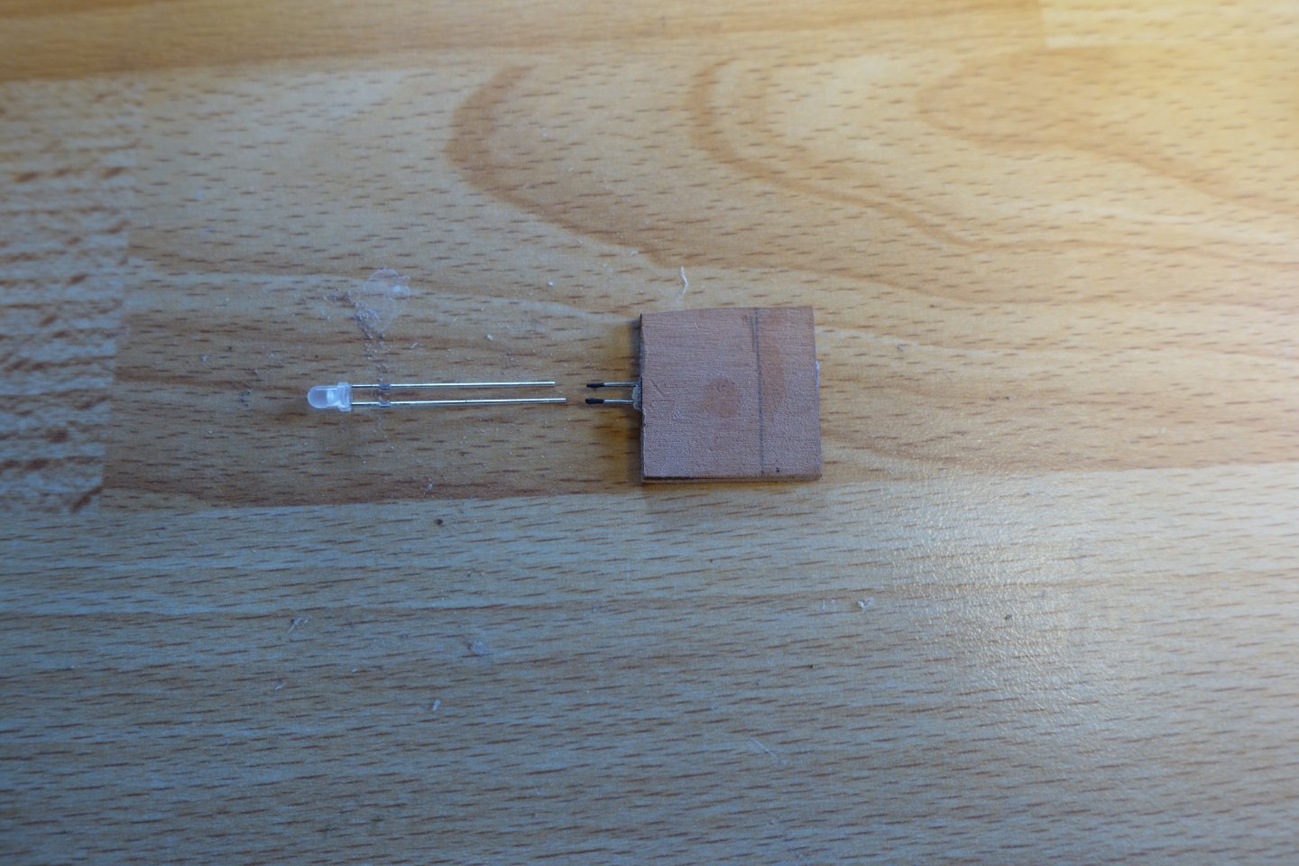
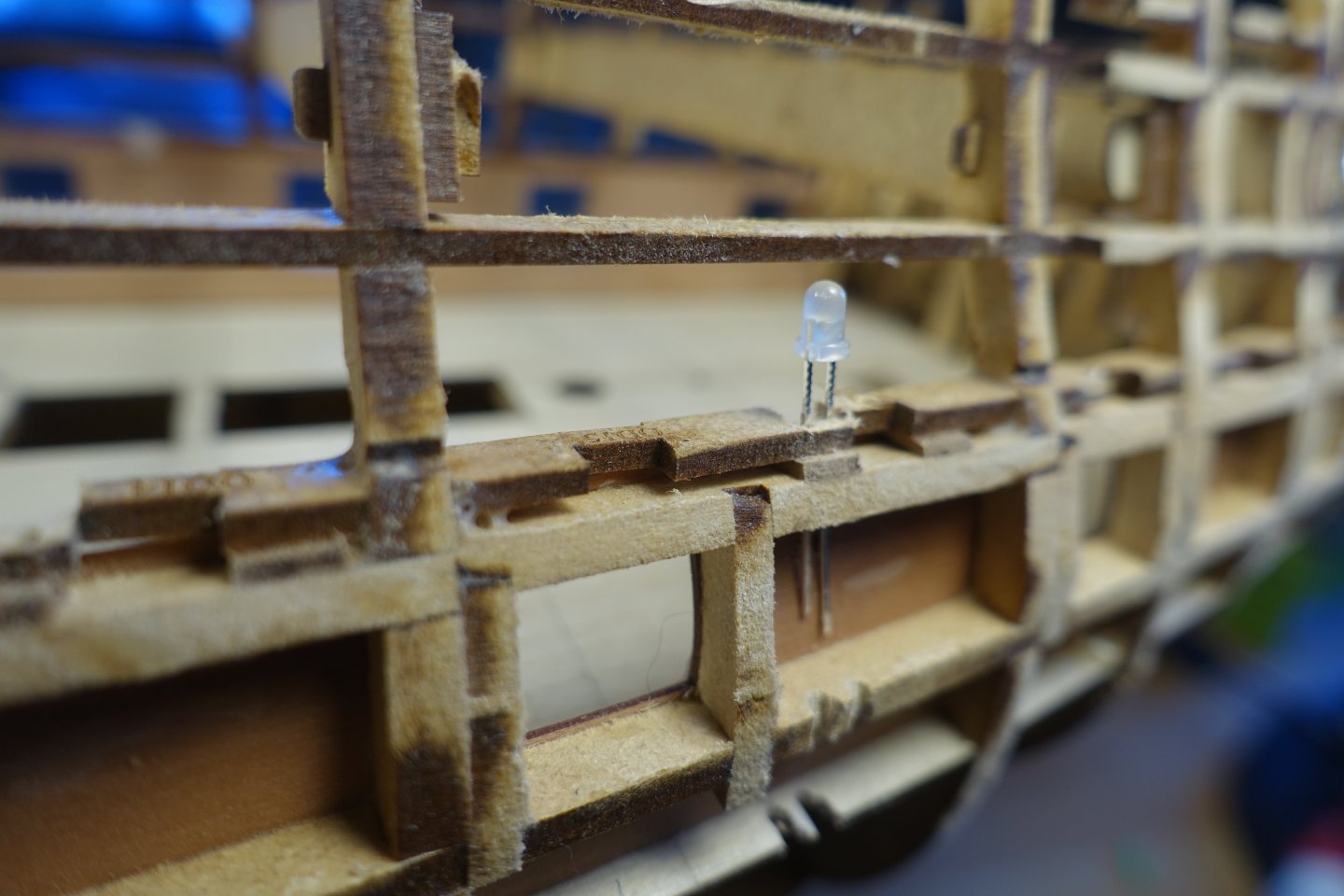
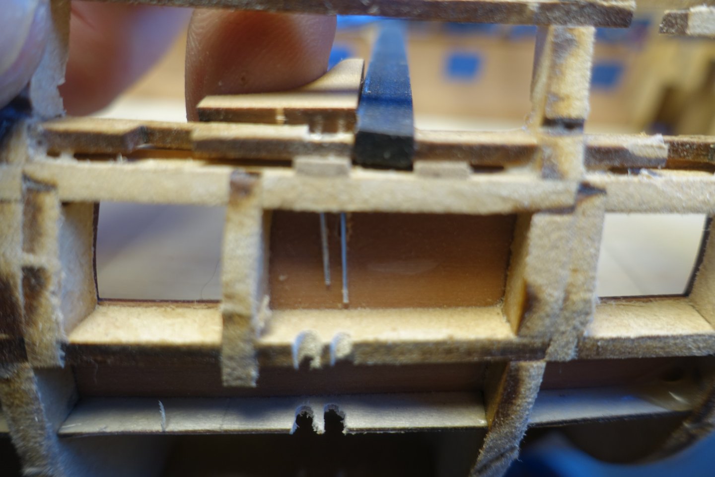
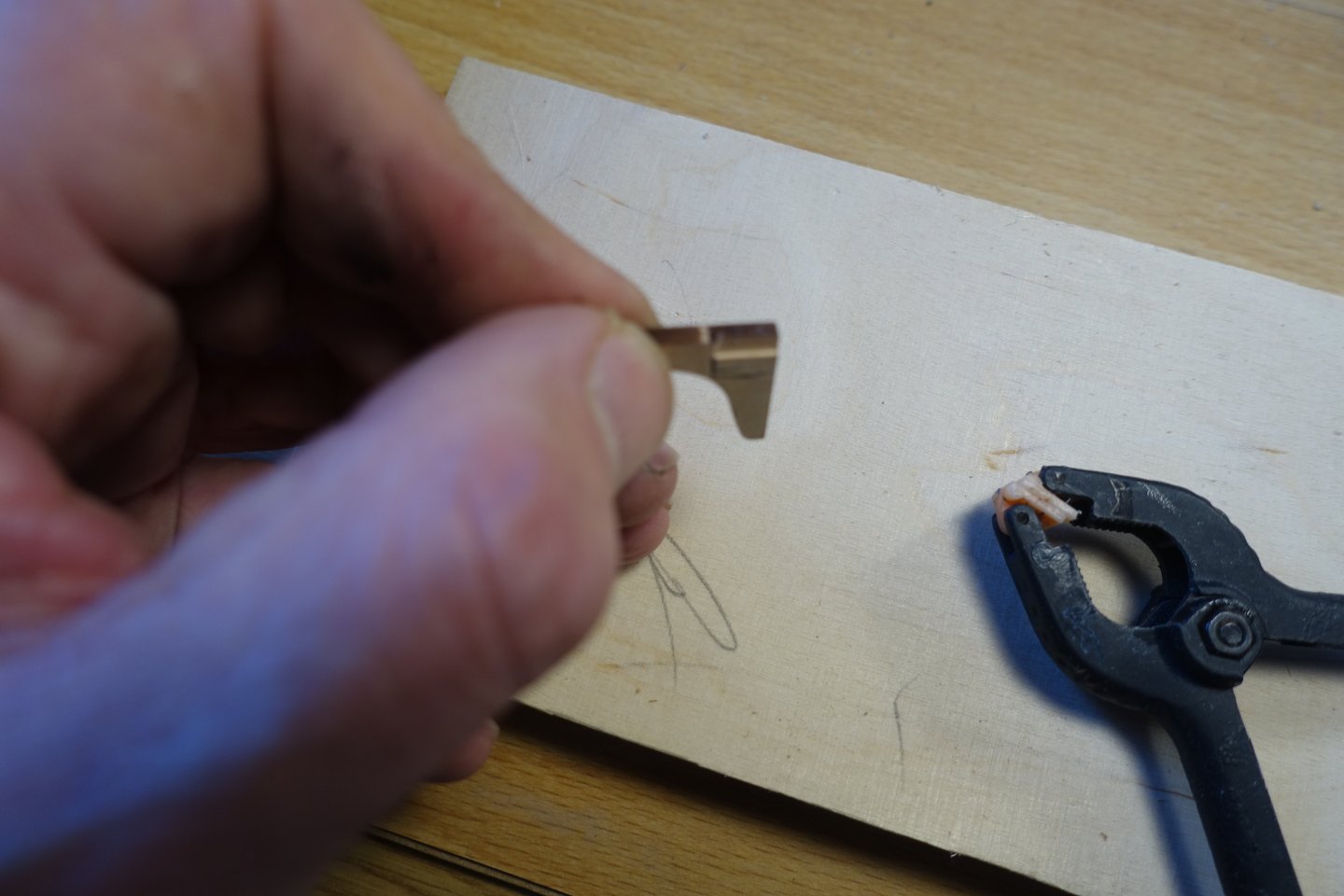
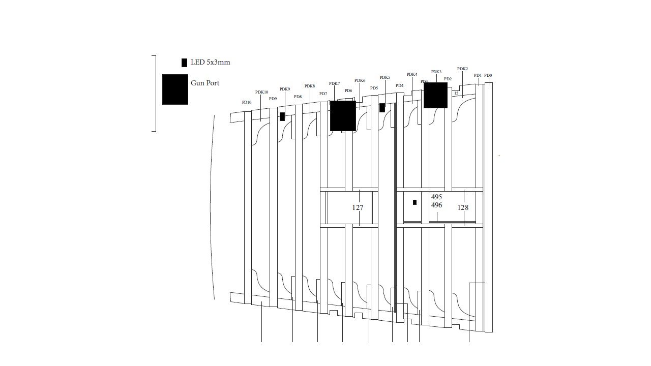
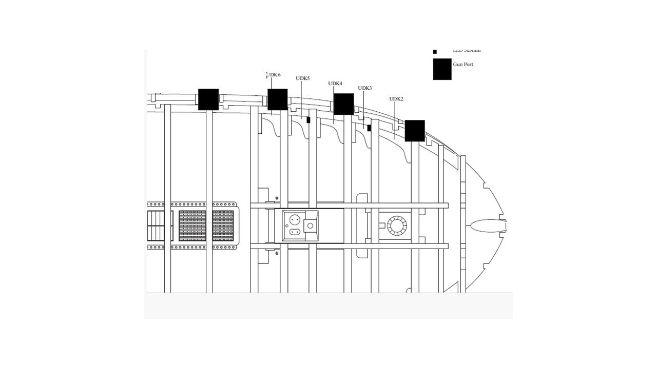
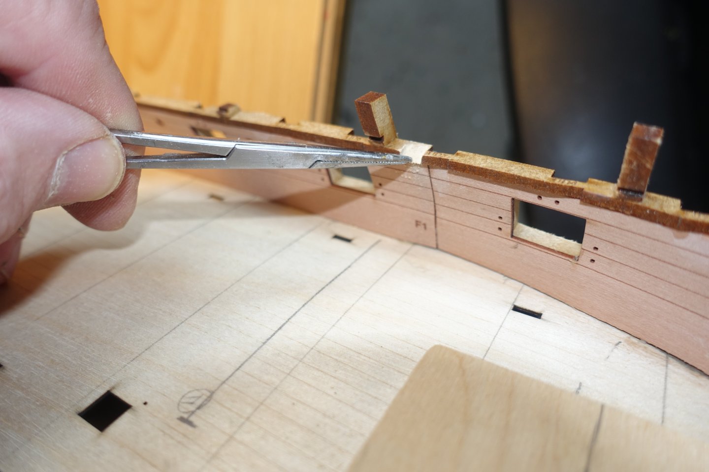
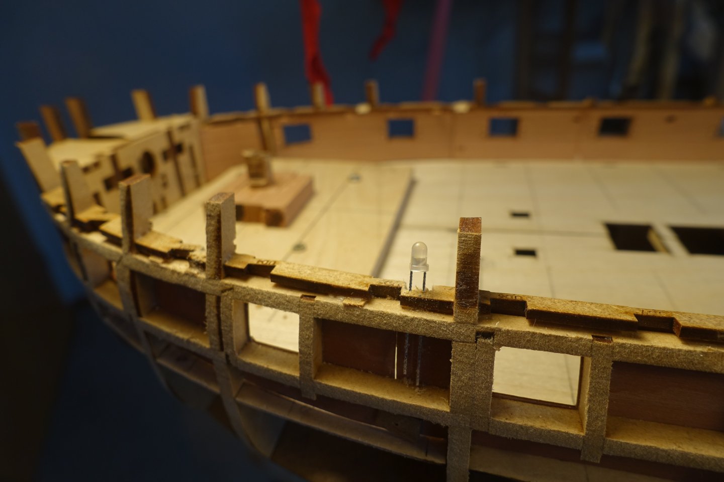
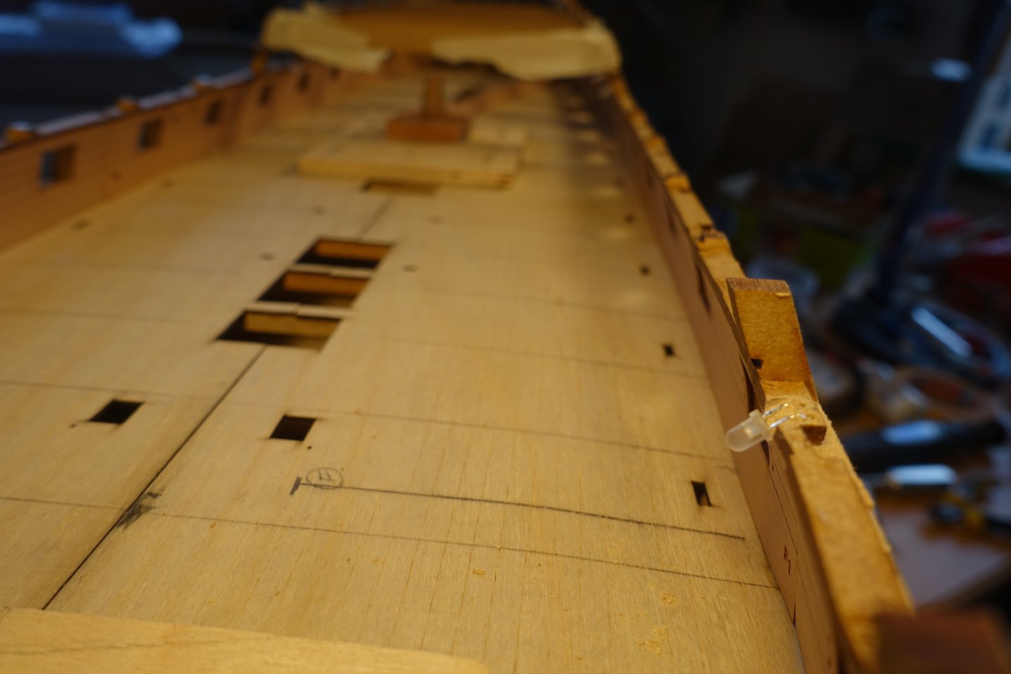
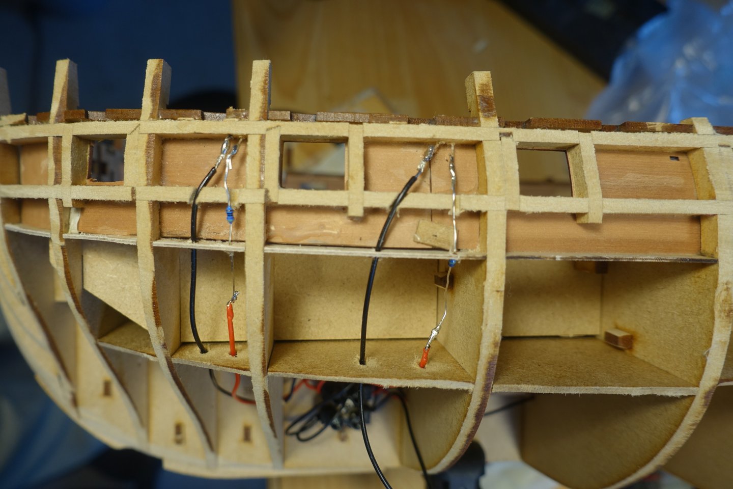
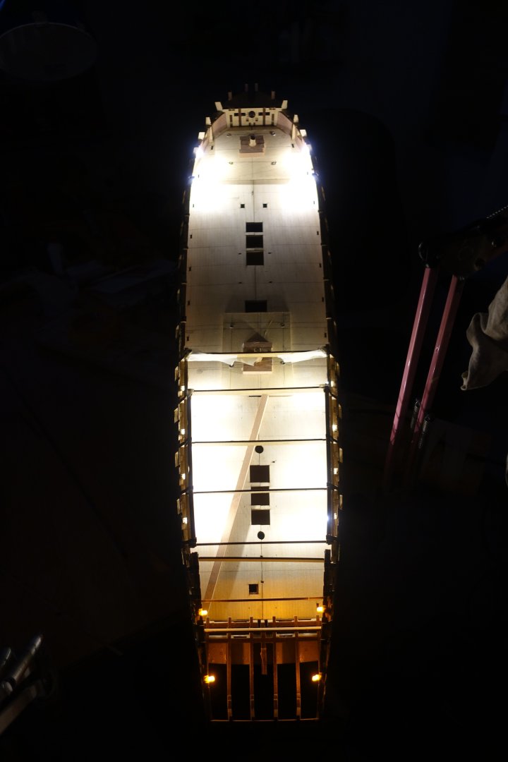
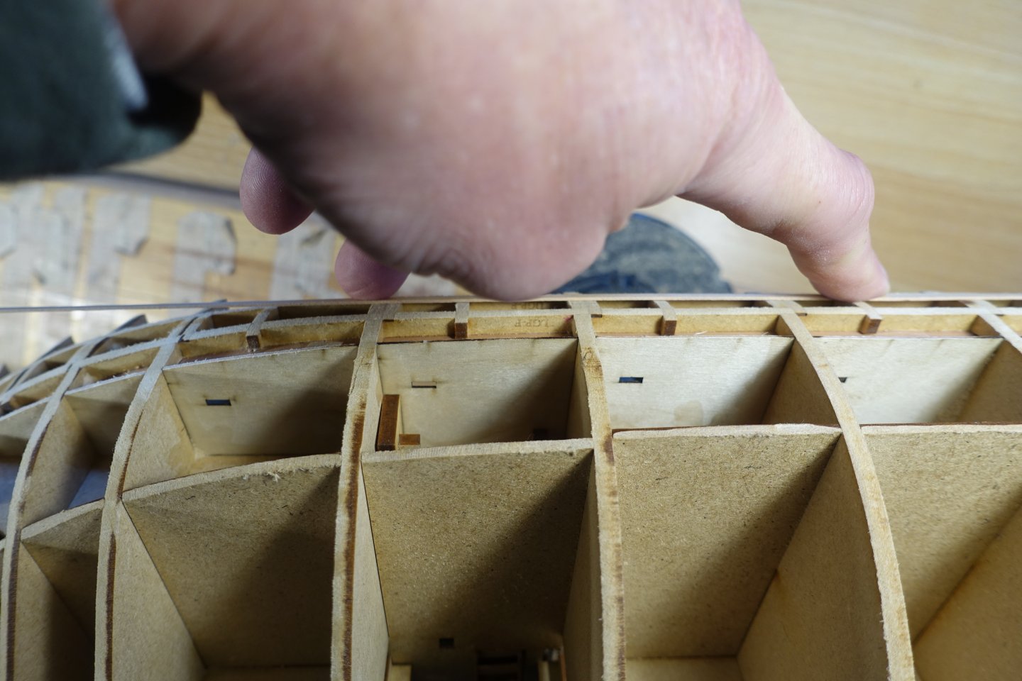
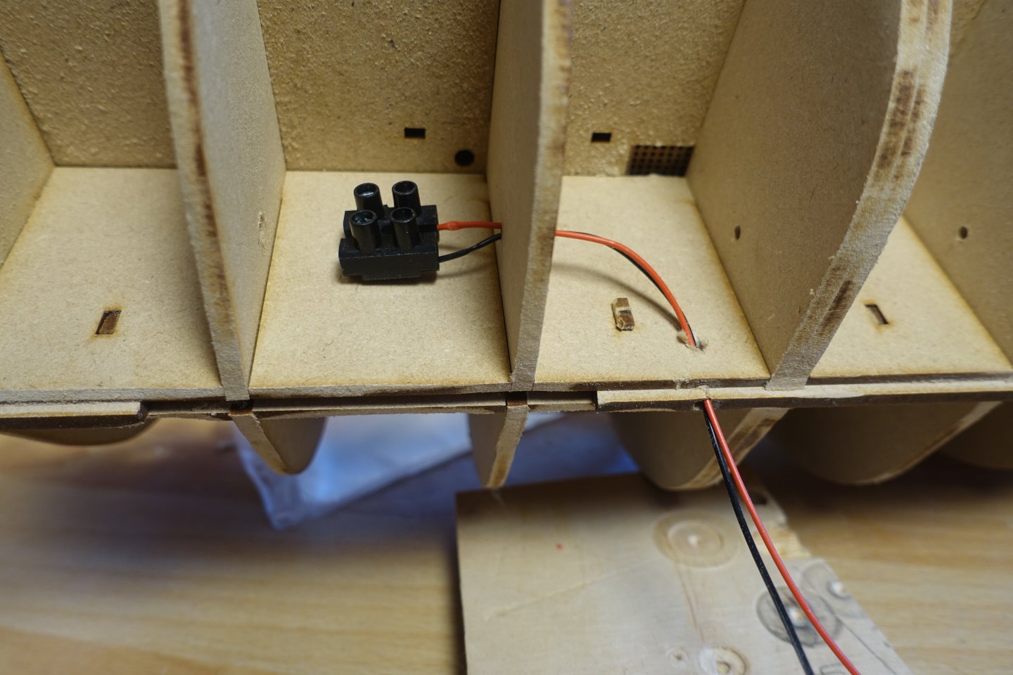
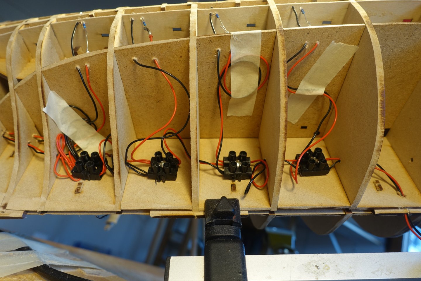
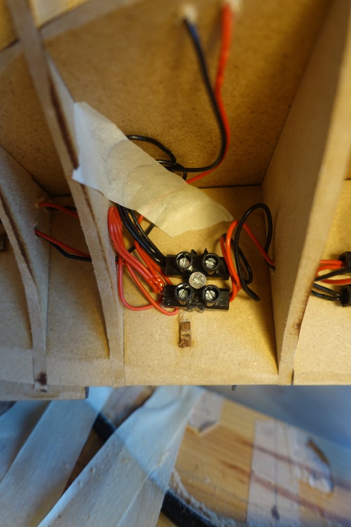
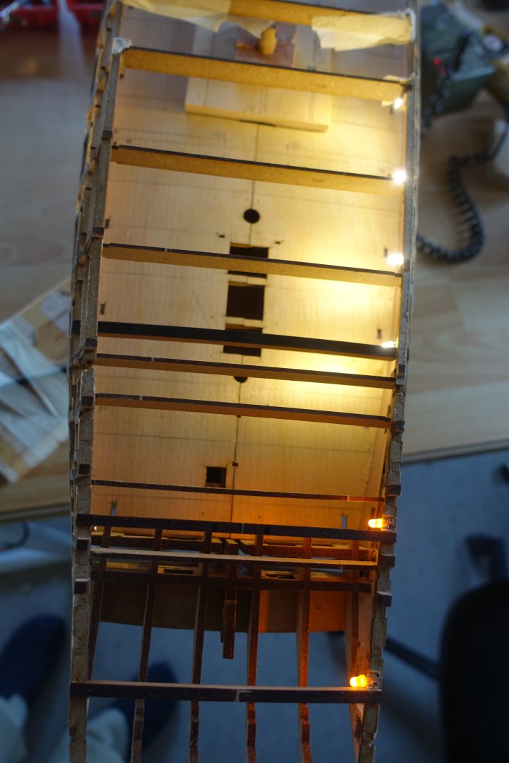
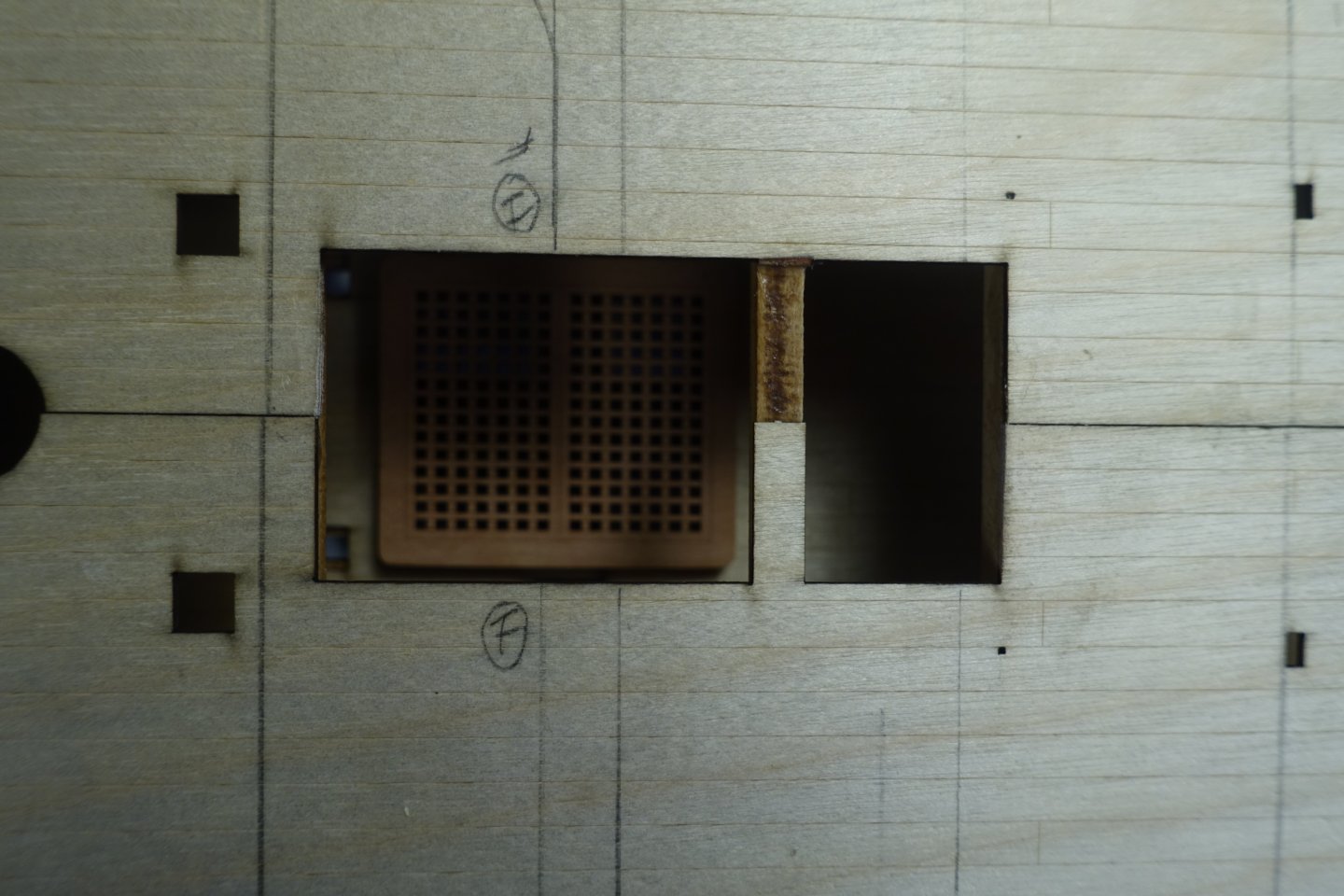
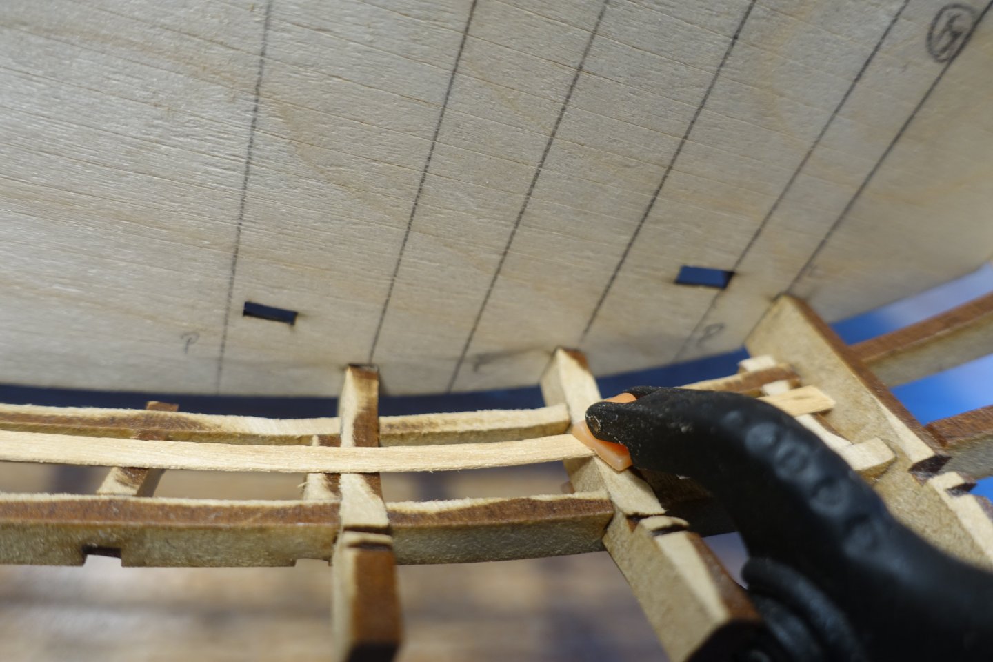
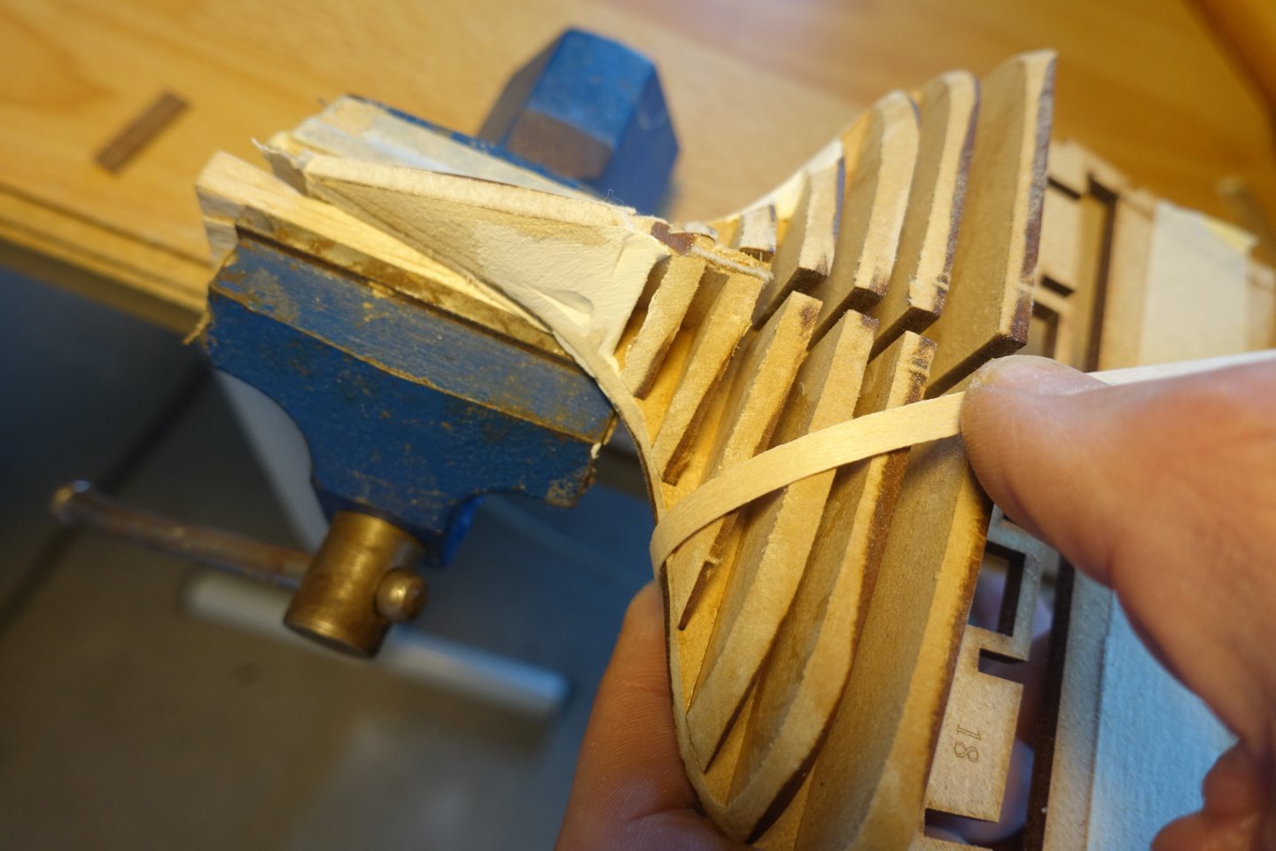
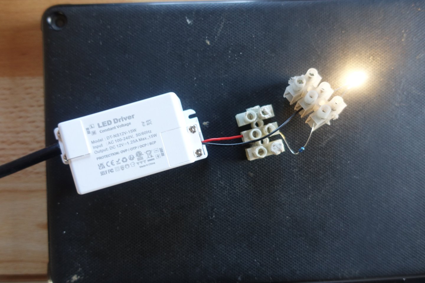
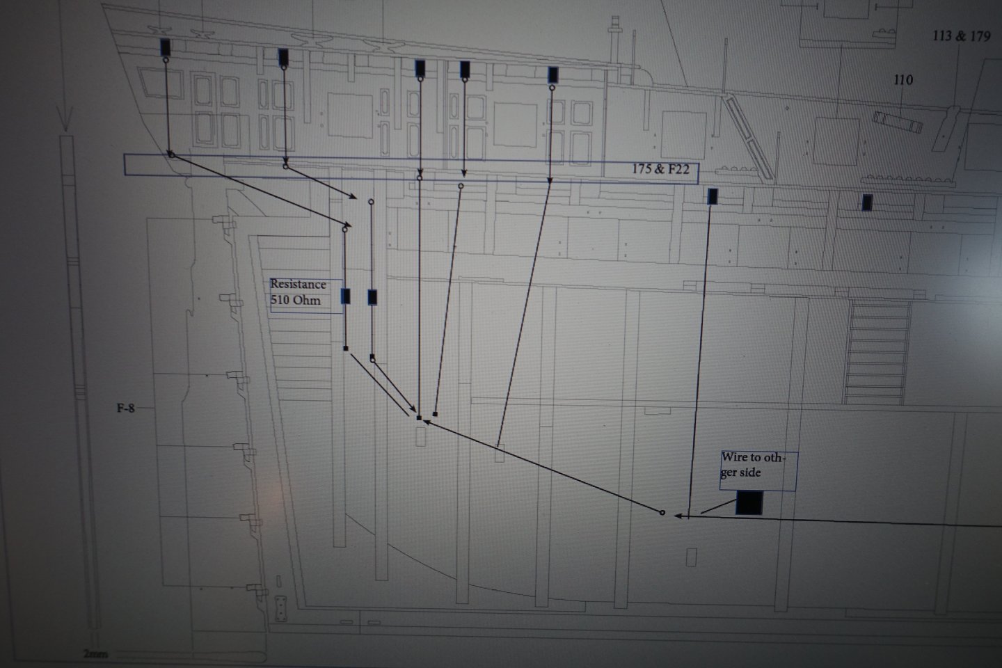
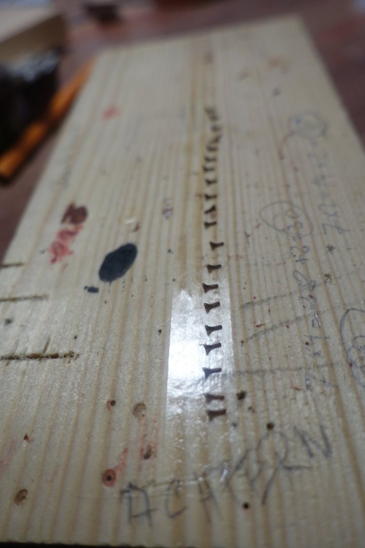
After my experience with the installation of the LED on the starboard side, I would like to explain the installation of the LED on the port side in more detail. This is described for the installation of the LED above the canon deck First of all, I got a rough idea of where to position the LED. The LED should not be visible from the outside or from above. That means they should be located away from the gun ports and also covered by the knee. Accordingly, there are only 4 positions where the LED can be attached for the rear gun deck. Under QDK 18 and upwards, it makes little sense to position the LED since this area is later covered by the poop deck. As can be seen from the illustration, the LEDs are to be attached towards the bow in front of the corresponding deck beams. First of all, I reinforced the corresponding areas by gluing in small pieces of strip between the support beam of the deck beams and the longitudinal beams of the gun ports. Marked by the tweezers in the picture. Then the area directly in front of the deck beam was filed down to the gun deck. This is to be able to bend the LED downwards later. Then the holes for the anode and cathode of the LED had to be drilled. To correctly determine the distance between anode and cathode, I built a small marking aid. This was given a little colour and then the marking was placed on the previously filed section After drilling the holes, the LED was inserted. To avoid getting confused, I always arranged the anode (long leg, ending at the red wire) on the right. Then the LED was bent over to the deck. It was checked whether the lying knee fits over it. About 0.5 mm of the thickness of the knee had to be removed in the LED area (sorry for the bad quality of the picture). Then the wiring was done, with me always connecting the resistor to the anode. As you can see, I am not an expert at soldering. I also made a rough plan for the LED under the poop deck. Since I want to leave the poop deck largely open later, I used yellow LEDs for this area. With the LEDs under the forecastle, it should be noted that the horizontal knees are attached with the orientation astern, so the LEDs and the recesses for them are positioned towards the stern behind the deck beams. Overall, I am very satisfied with the effect.


-
Did you ever try wipe on poly (wop) for the natural wood? Otherwise you may try the variants on wood remnants precoloured. Clark
-
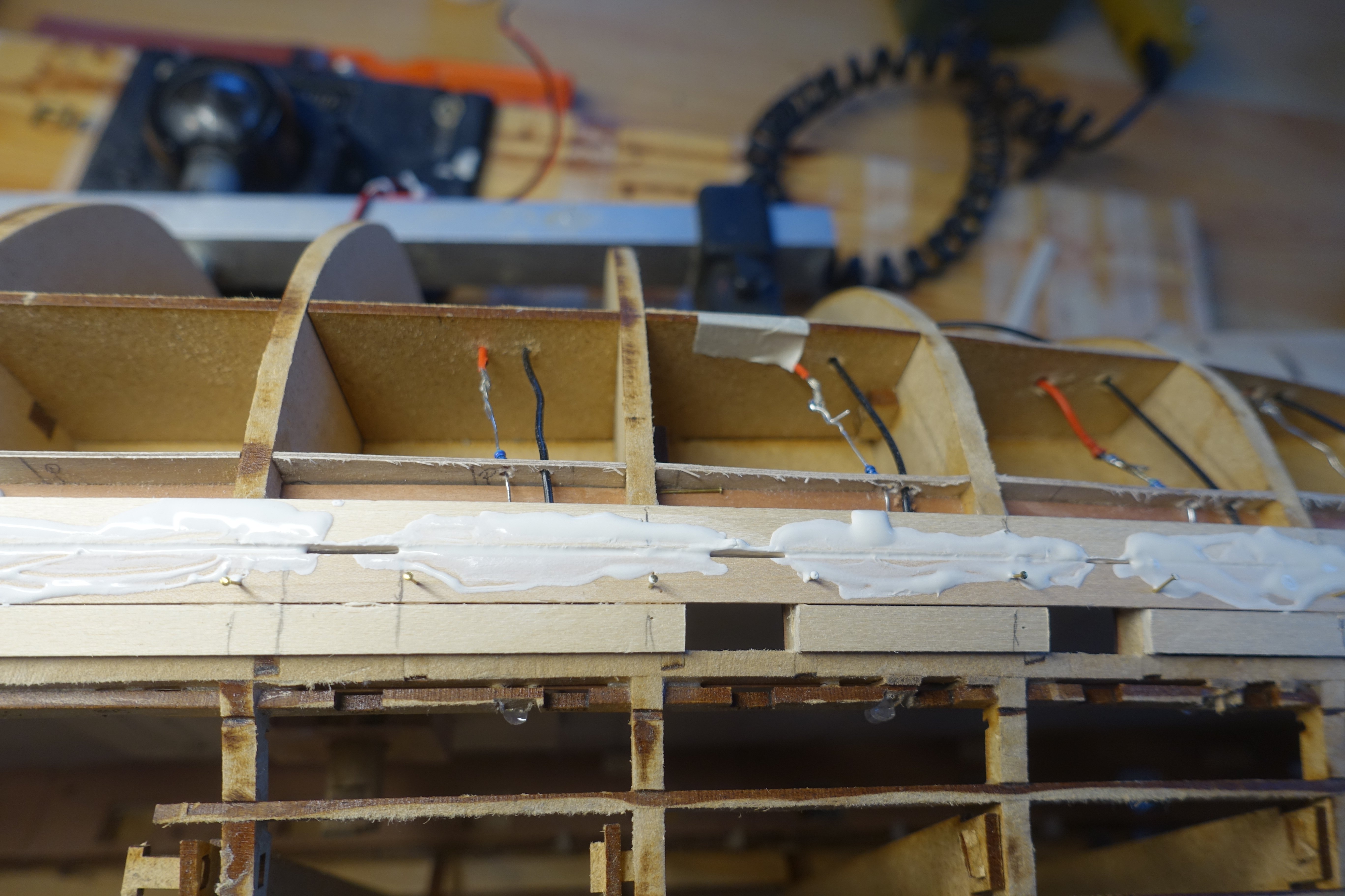
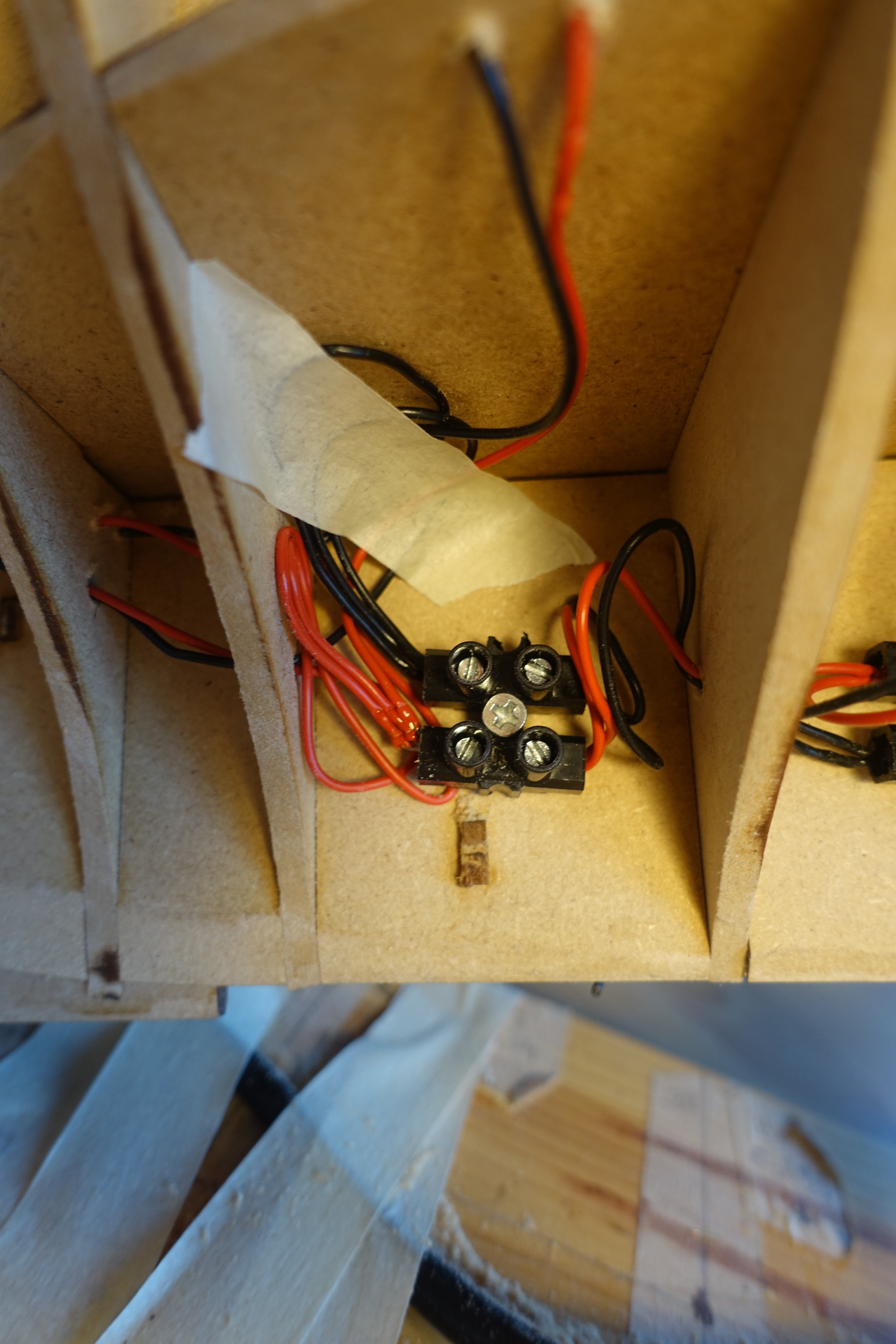
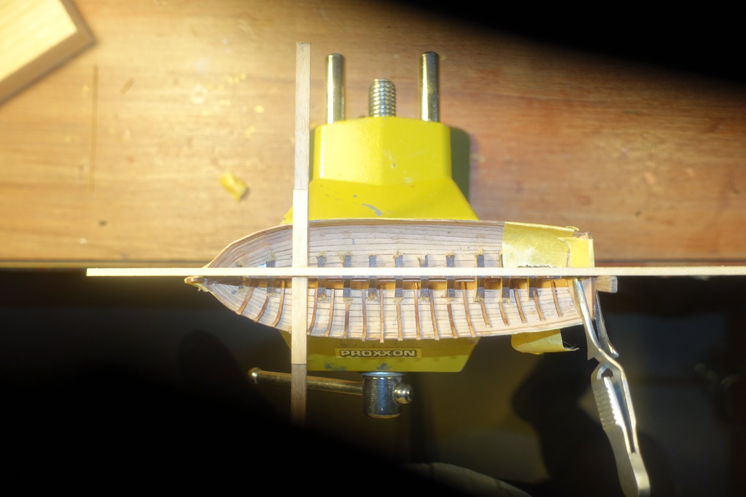
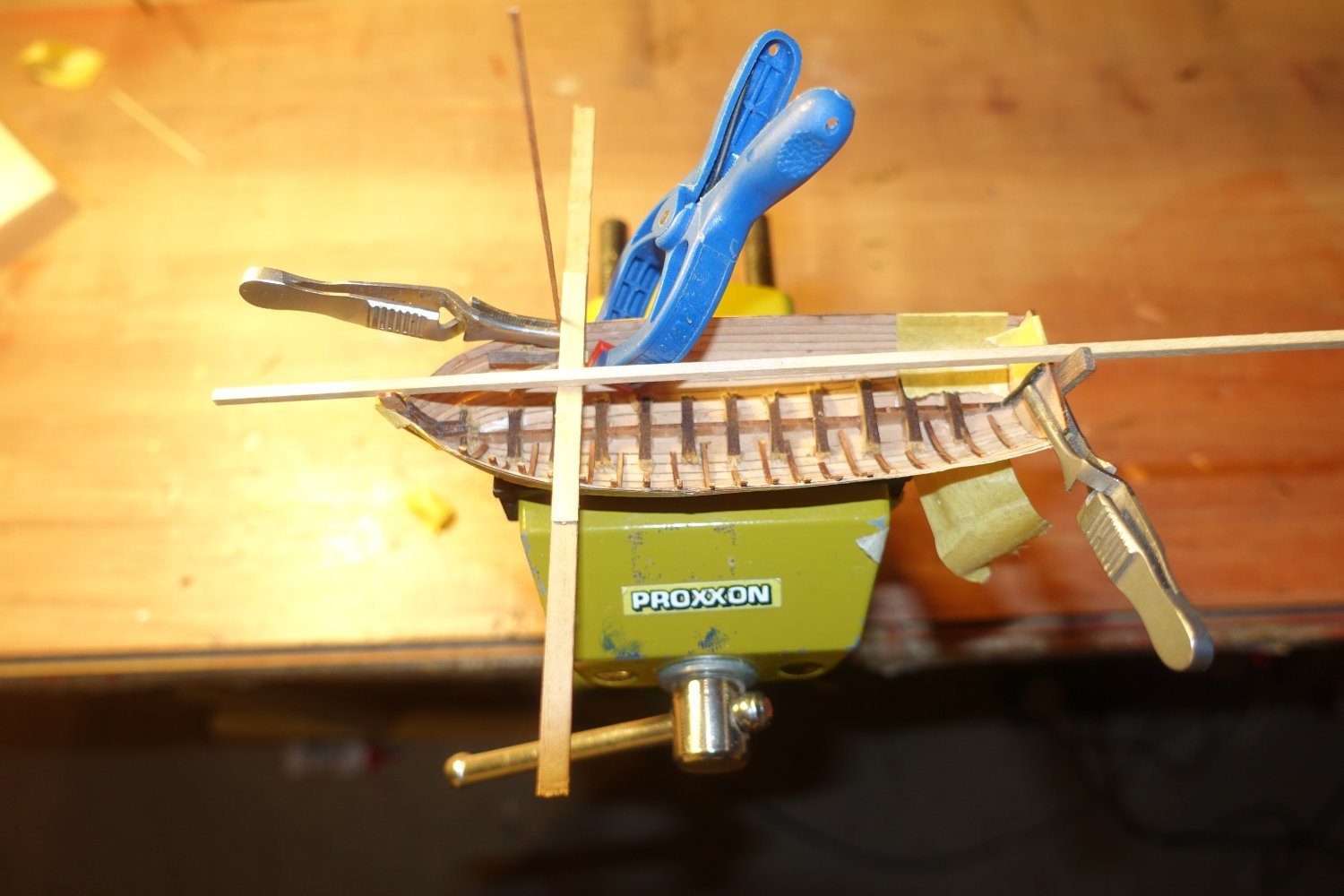
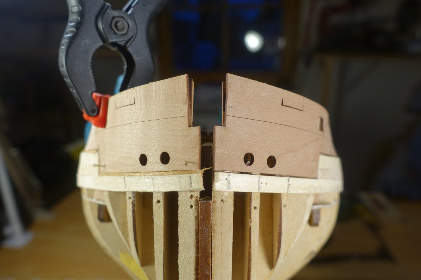
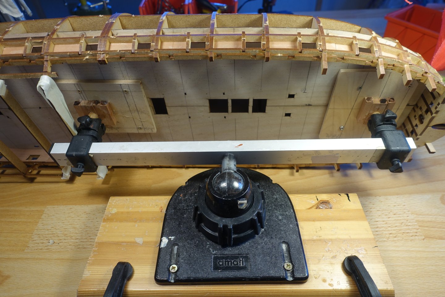
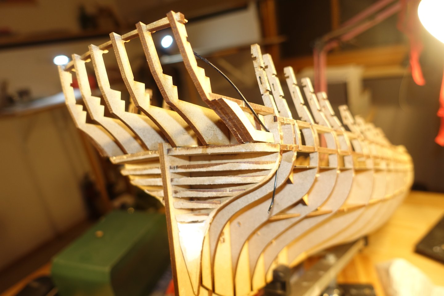
The projection shown in the previous post is bridged by a small strip on the back so that the two sections of the bulwark are now in line on the front. The supports for the deck beams were glued in, with the alignment being ensured by means of a dry fitting of the beams. To sand the bulkheads, the Indy was clamped overhead in the Amati clamping device using the dowels inserted in the fore and main mast openings. I first sanded with a Dremel and then with the self-made sanding sticks that I had already used on the inner bulwark (80 grit). I checked the fit with a strip, especially in the area of the gun ports. Then I started the LED wiring. The wired were fed through the centre of the keel between bulkheads 9 and 10. The branches for one LED above the gun deck then went between two bulkheads till I reached the space between bulkheads 13 and 14. Then it got tight. Therefore, from the luster terminal between bulkheads 13 and 14 the following wiring was installed: 1x supply for the last LED above the main gun deck. 2x supply for two LEDs (yellow) above the quarterdeck/under the poop deck 1x supply for the port side. It all looks pretty messy, but it works. I have had my experiences with laying the cables on the starboard side. I hope to be able to show an improved installation of the LED on the port side in the next post. Happy New Year

-
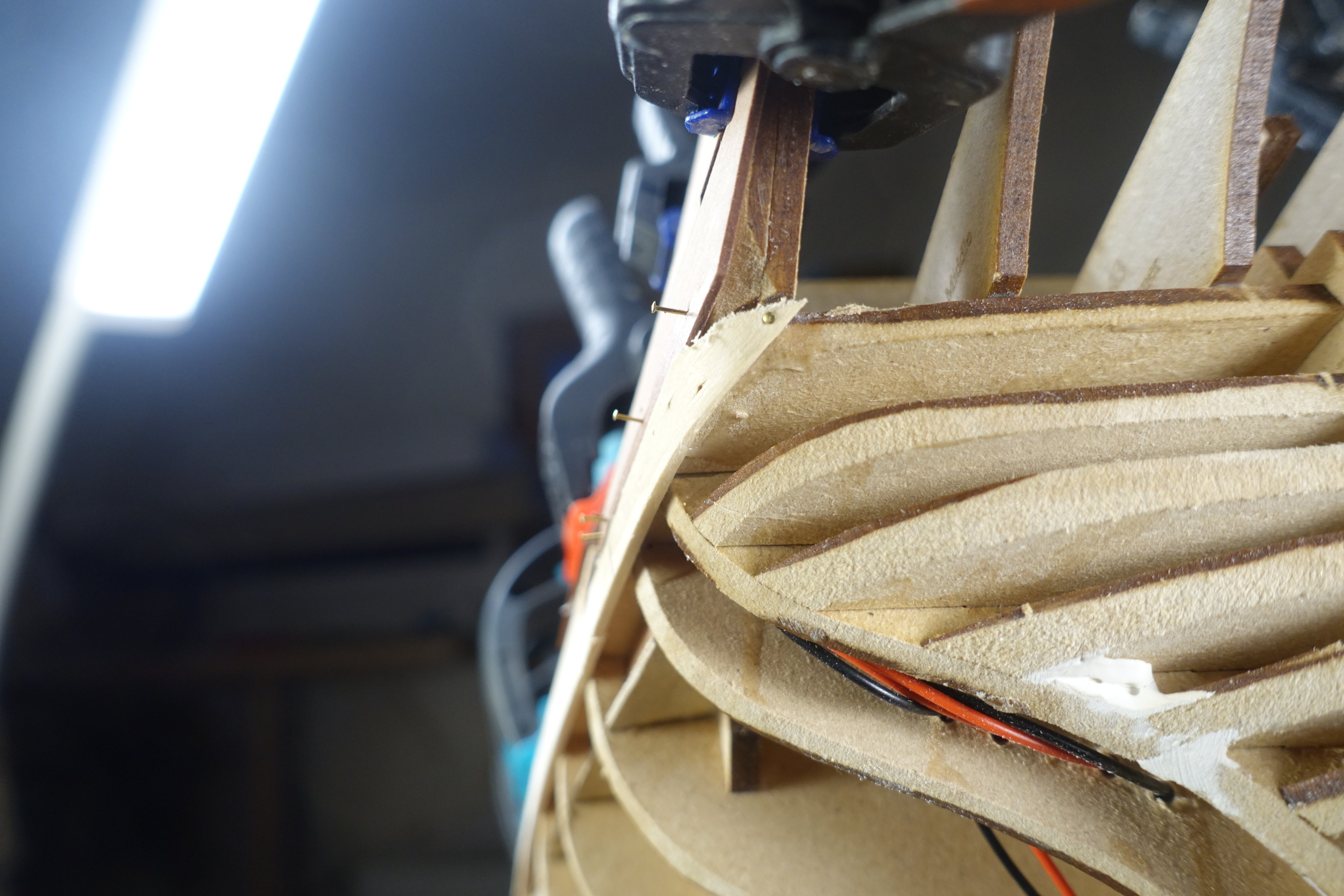
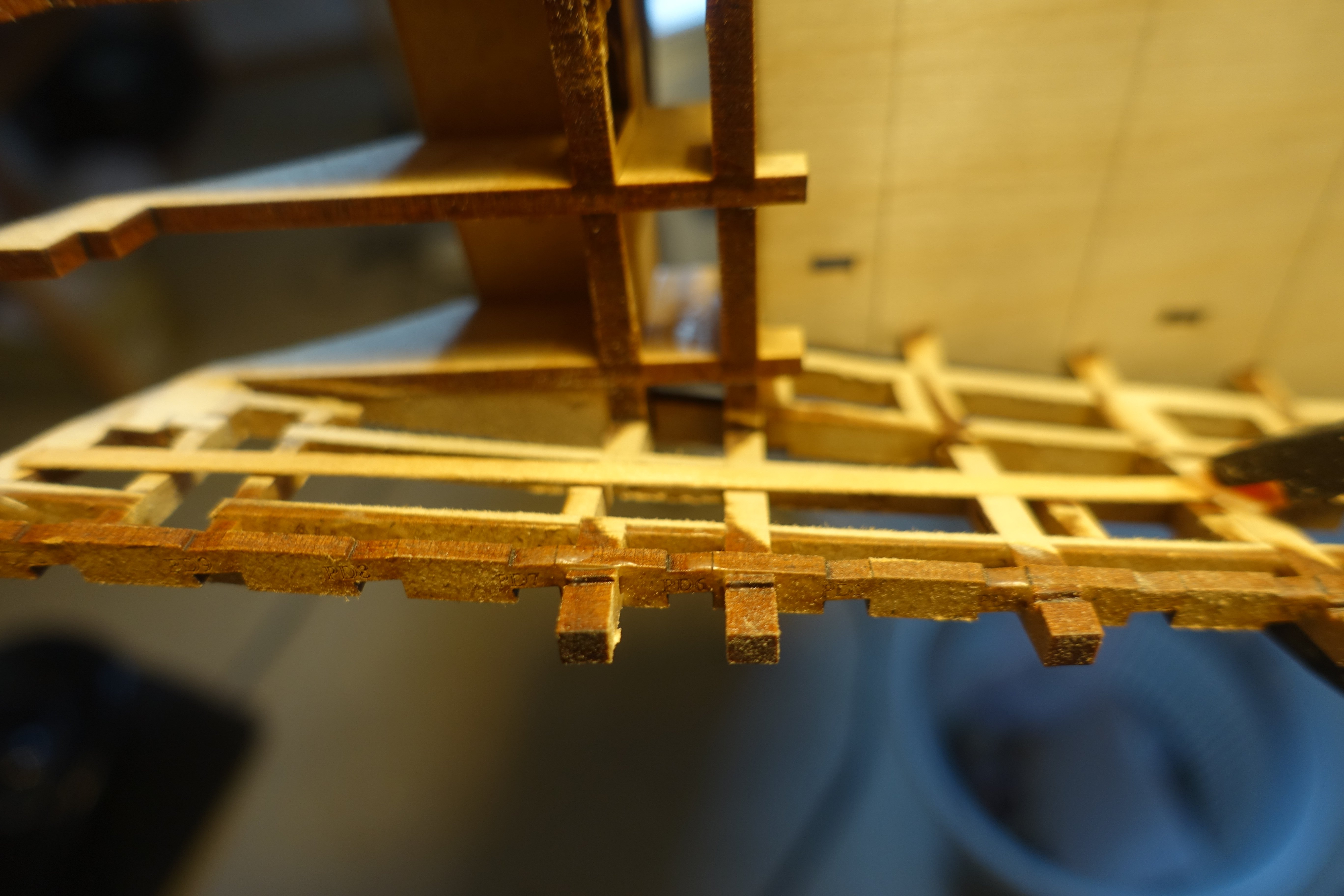
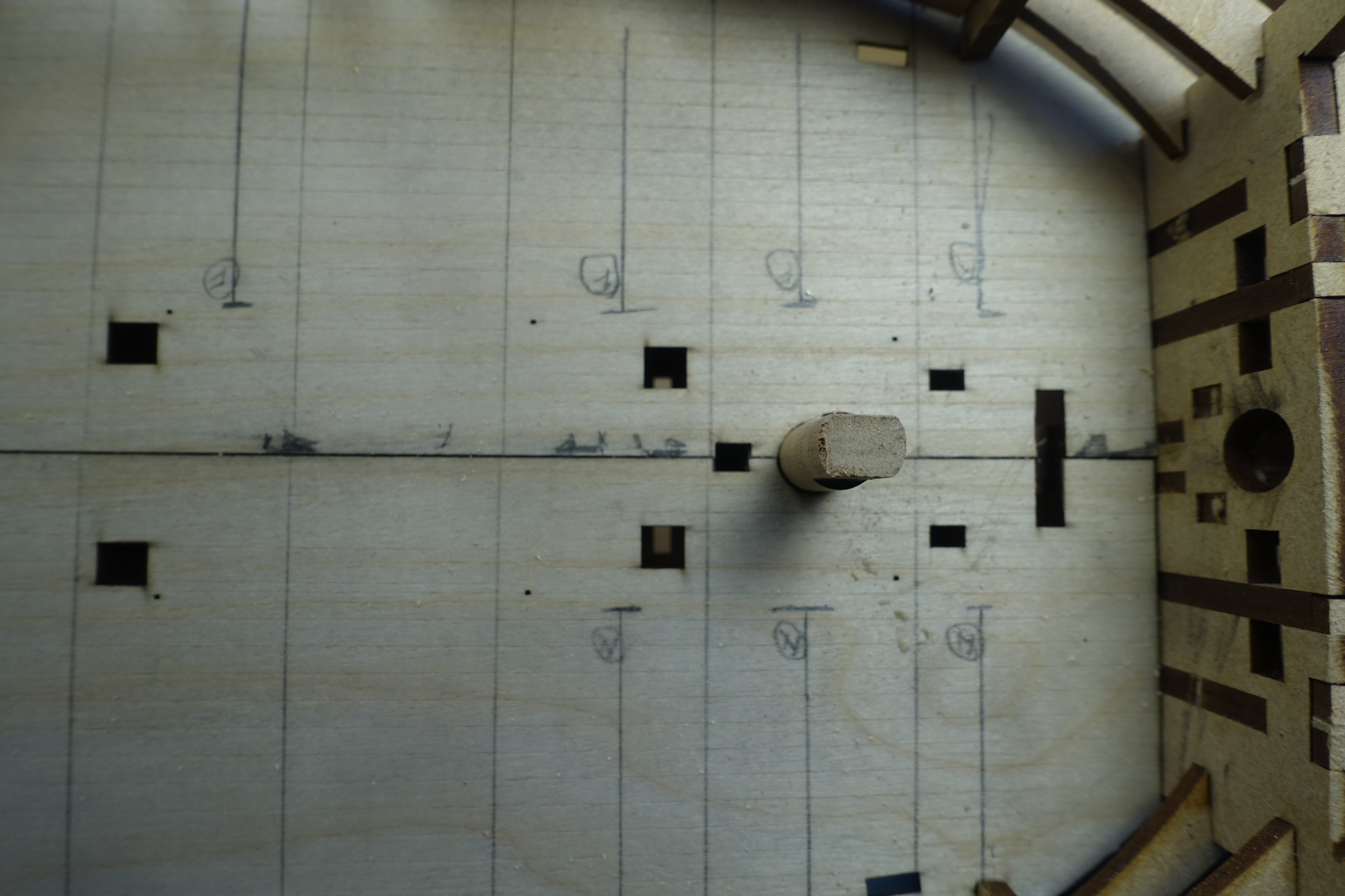
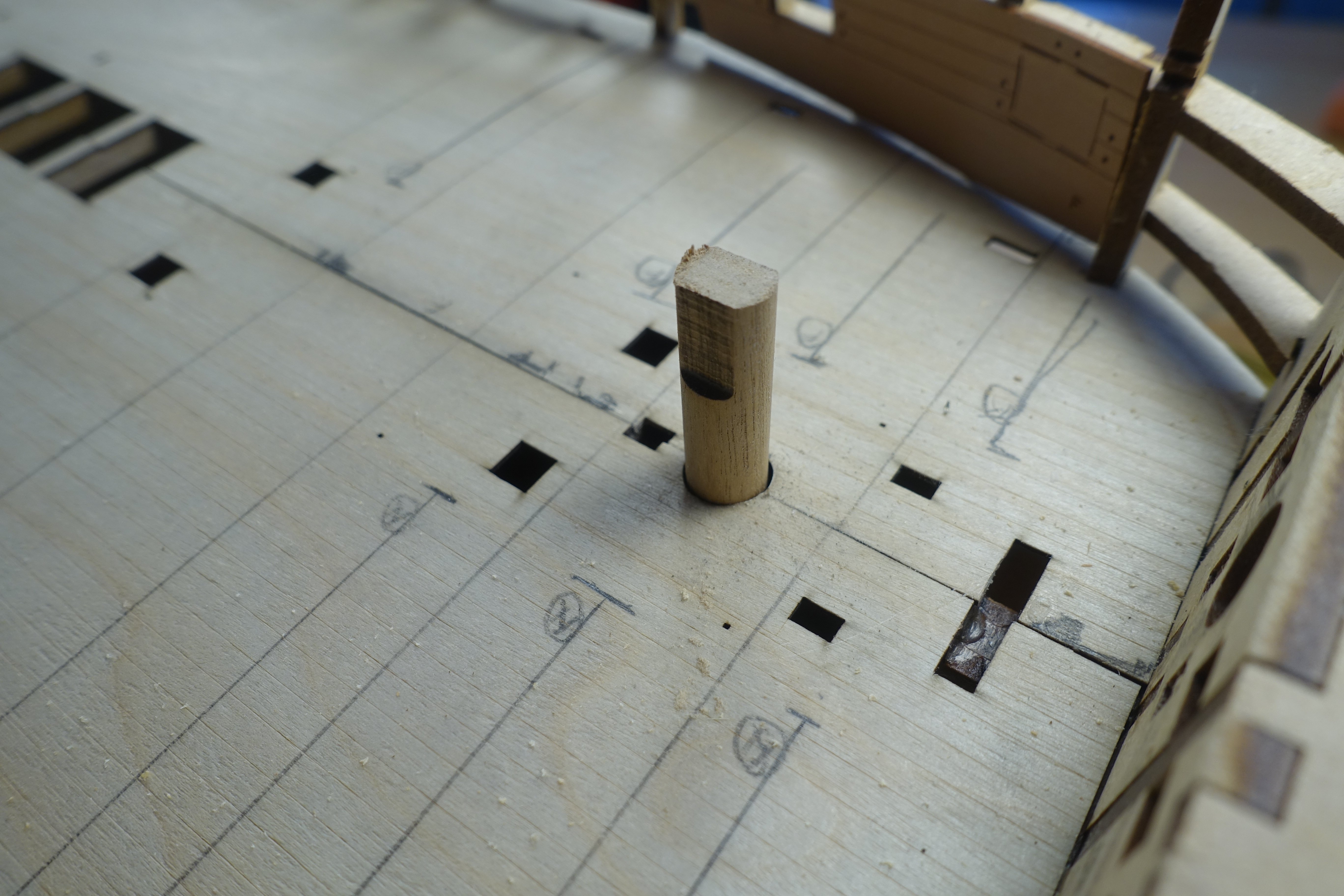
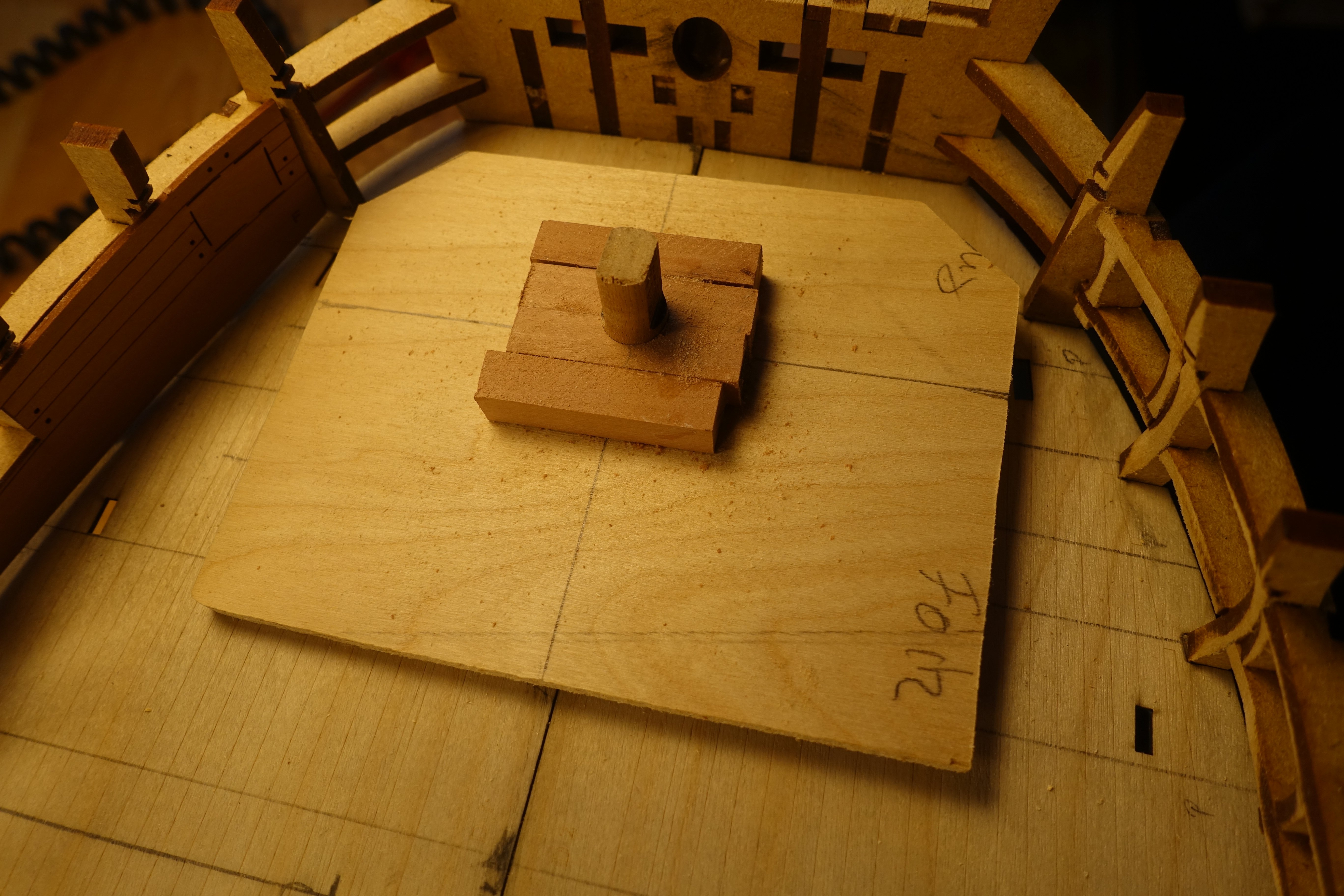
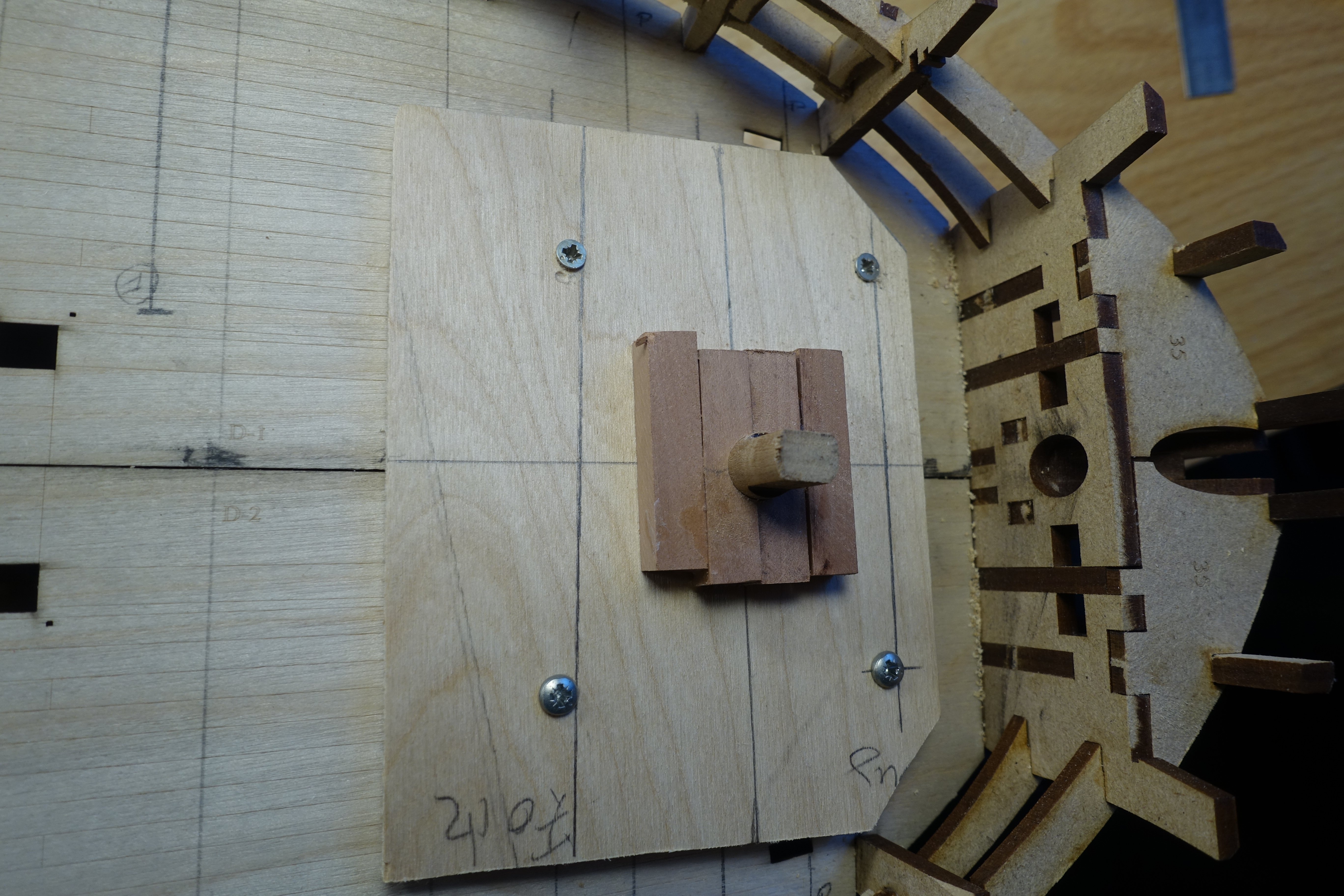
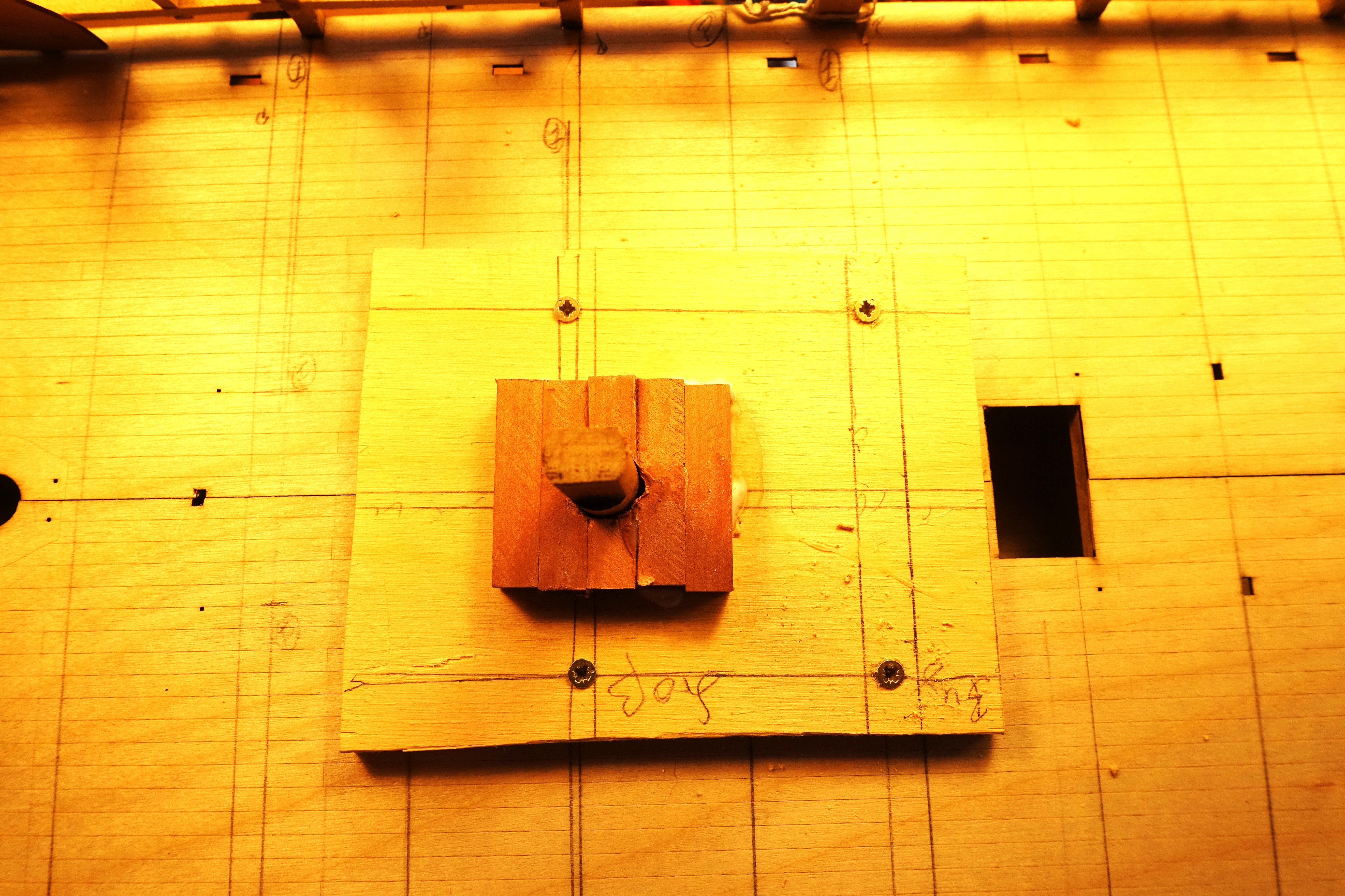
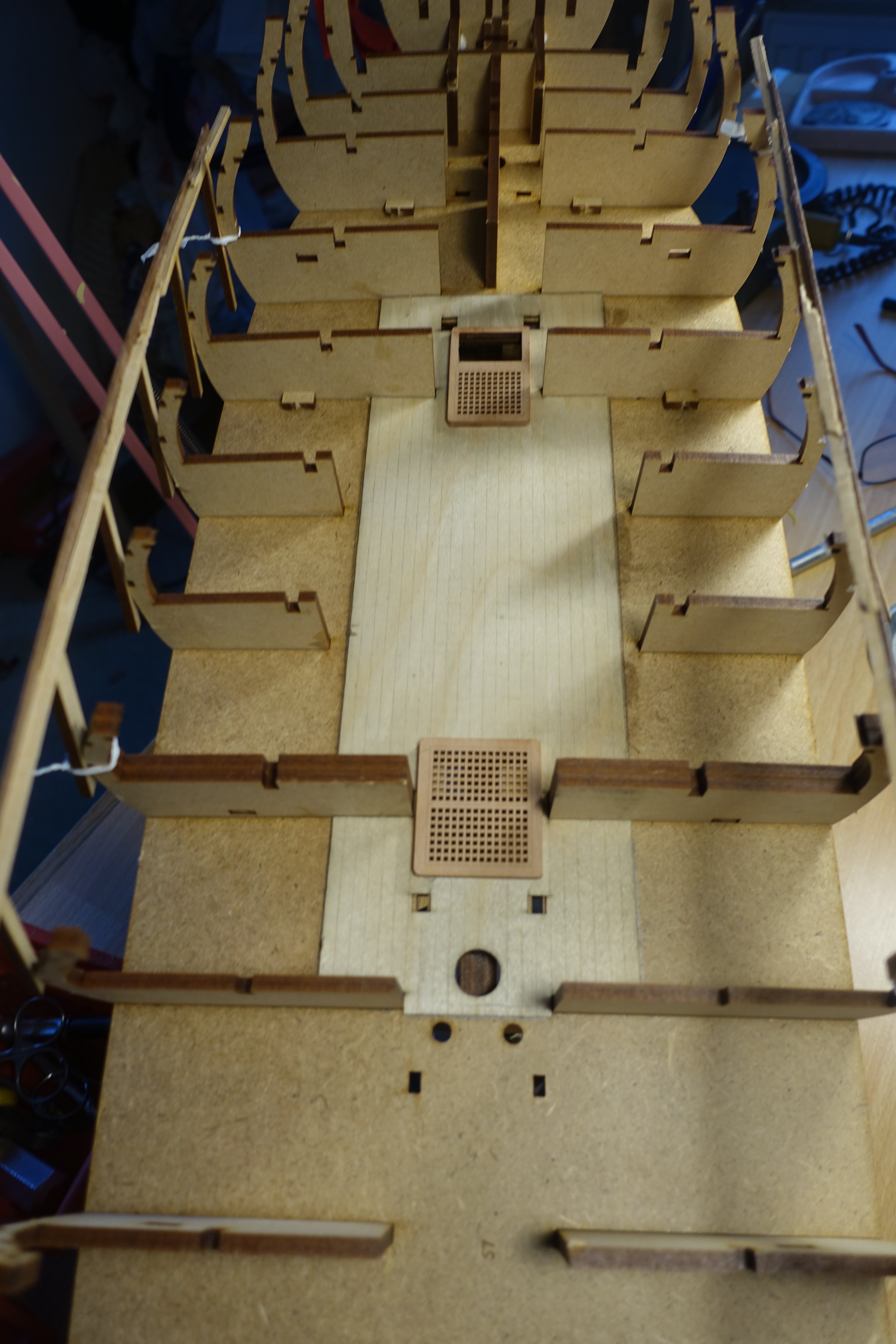
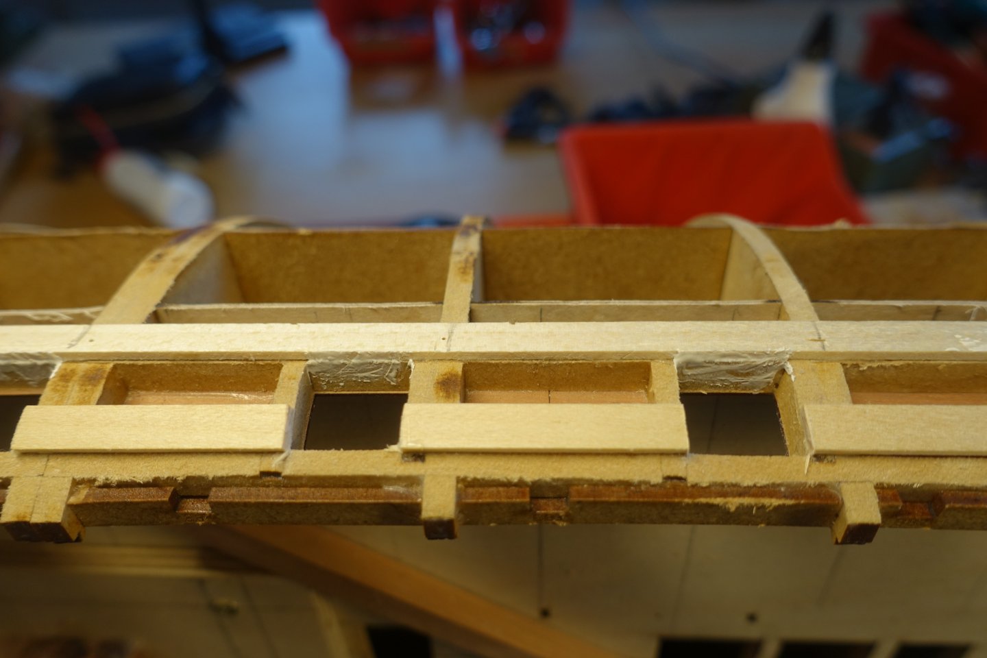
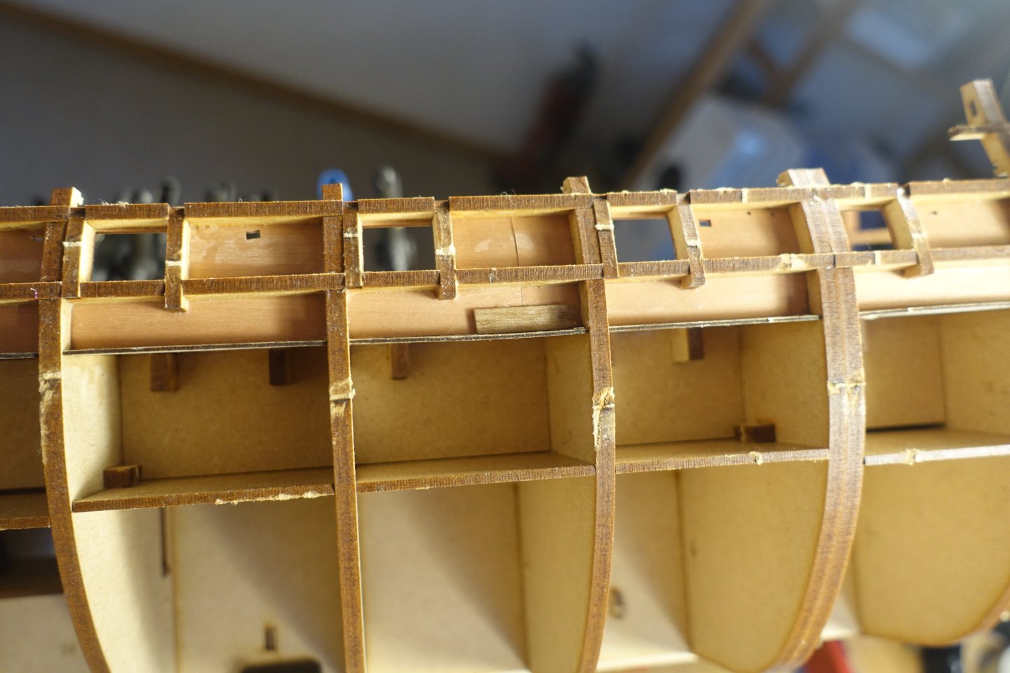
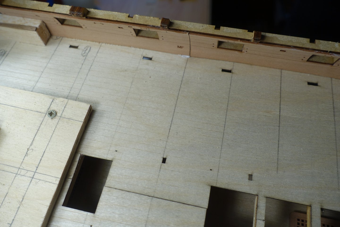
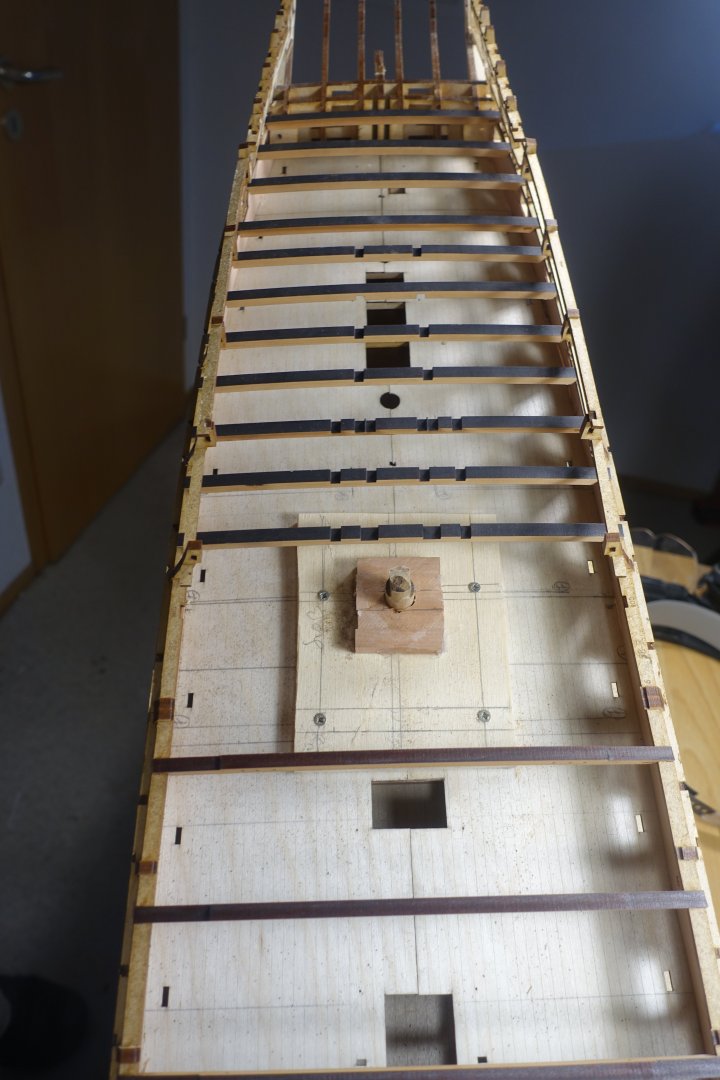
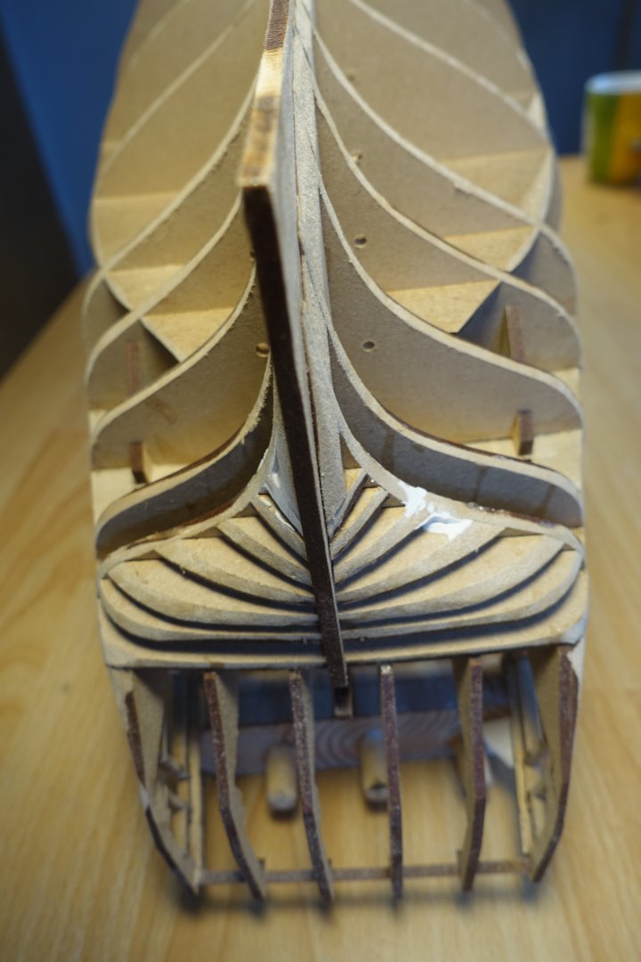
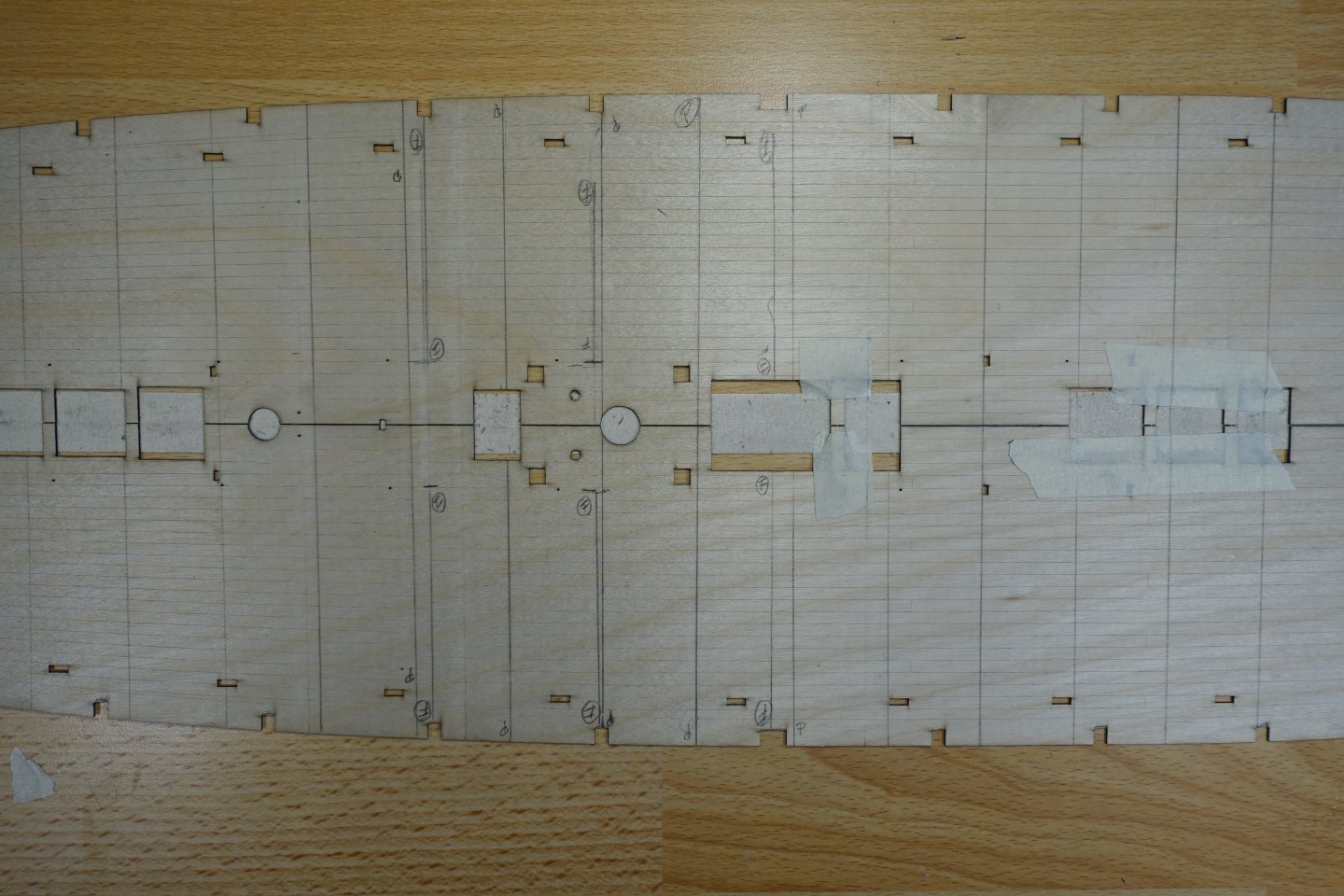
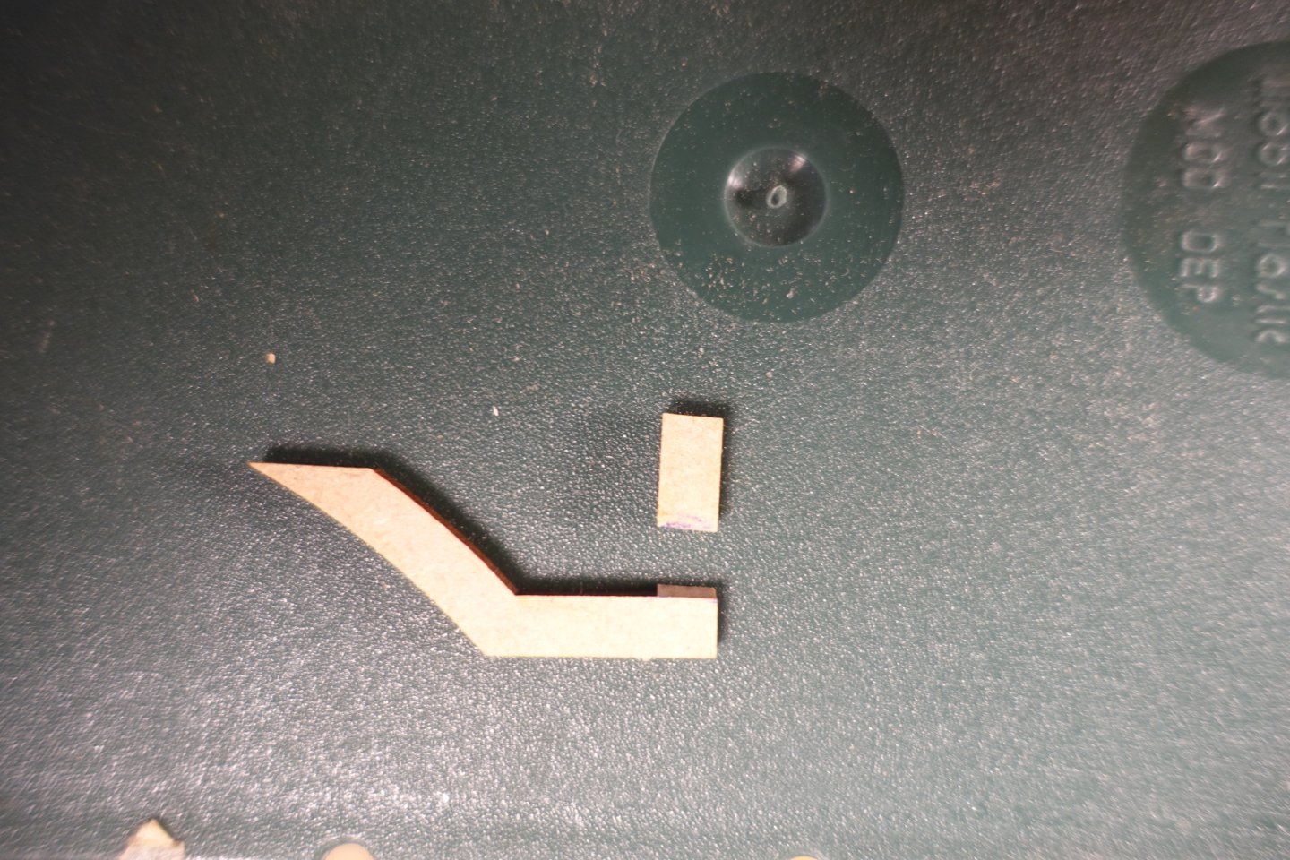
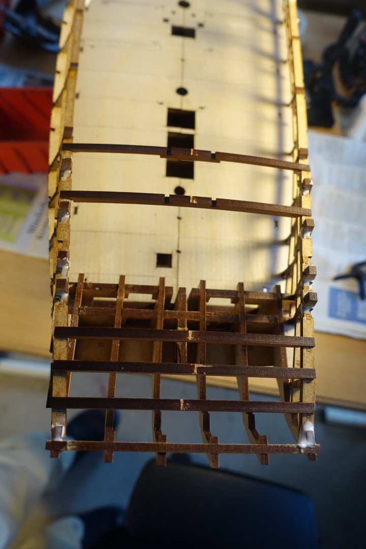
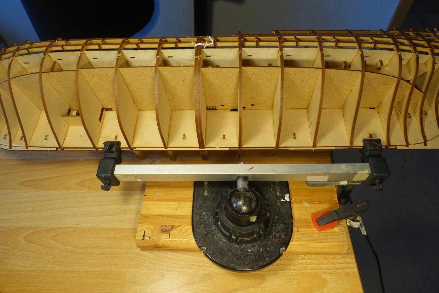
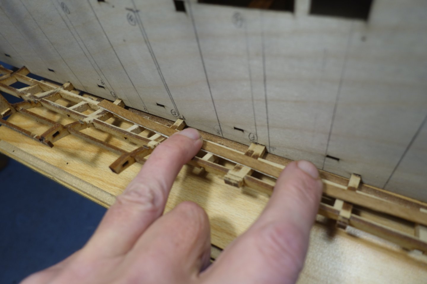
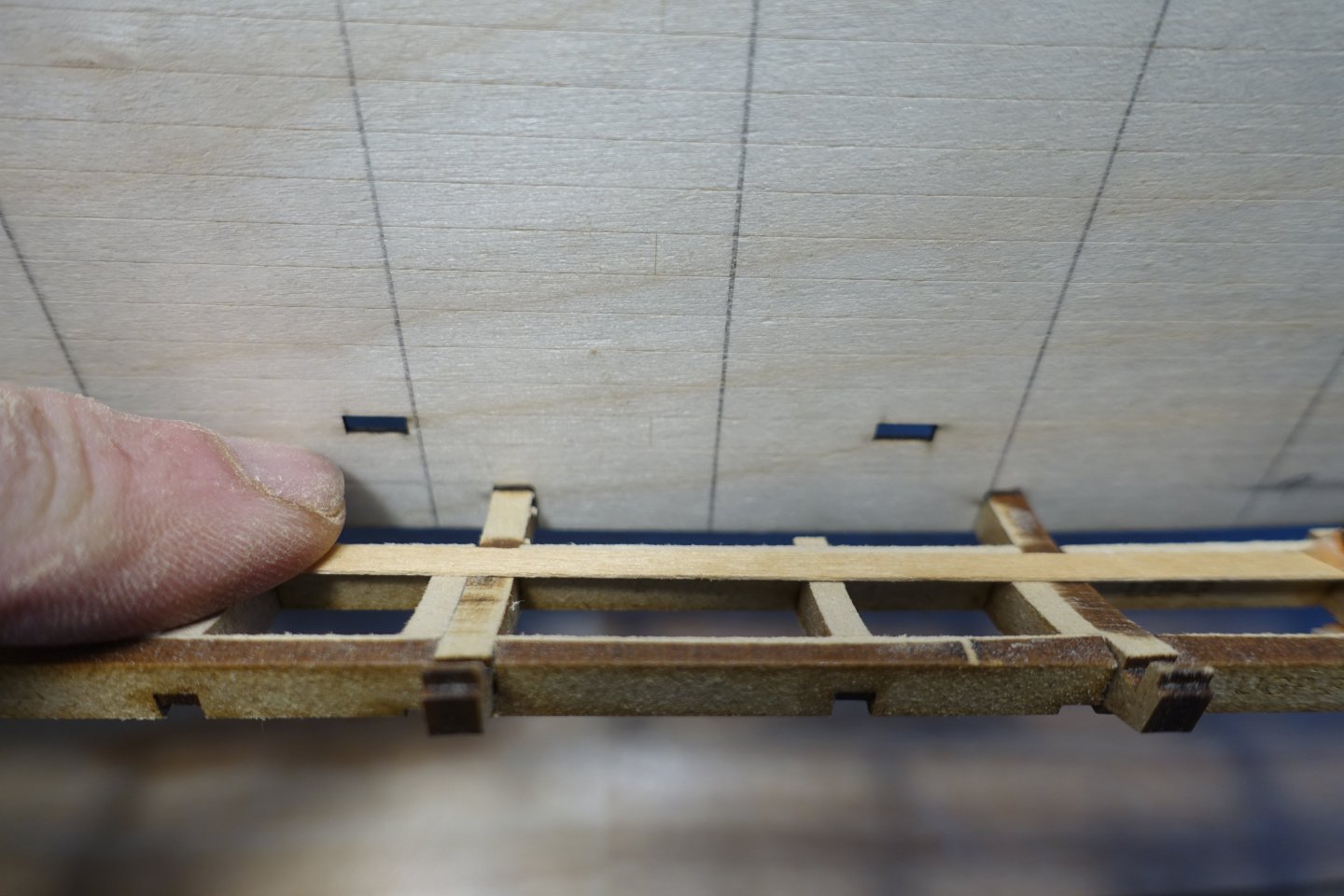
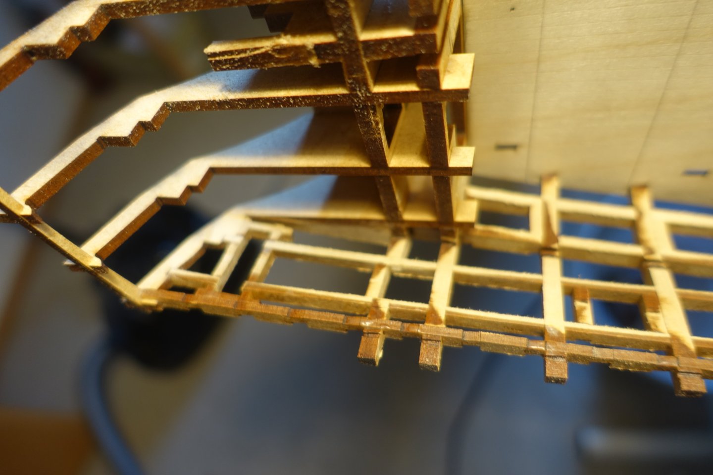
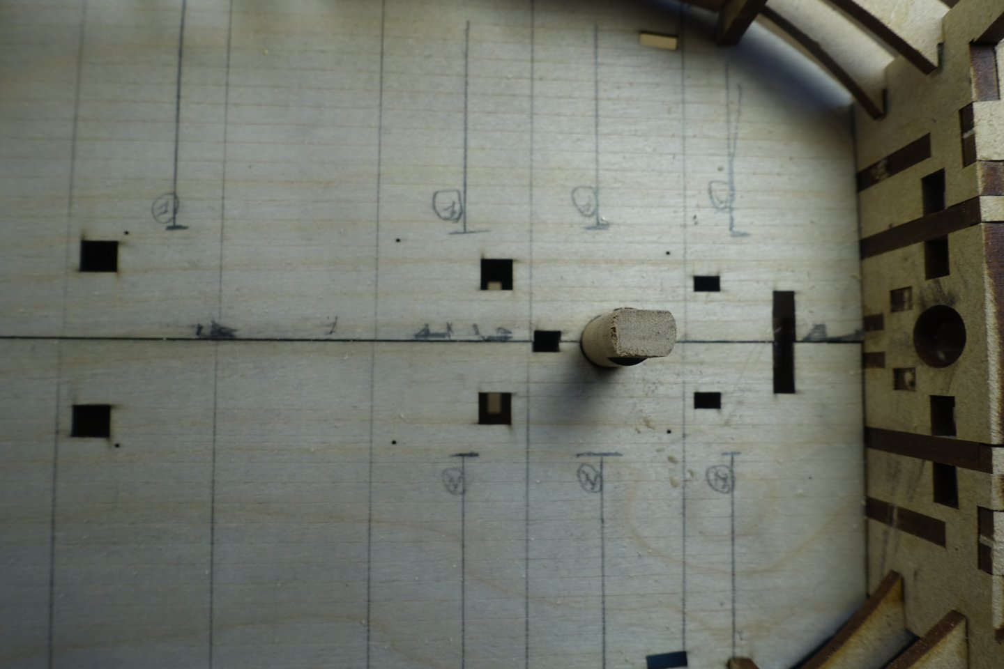
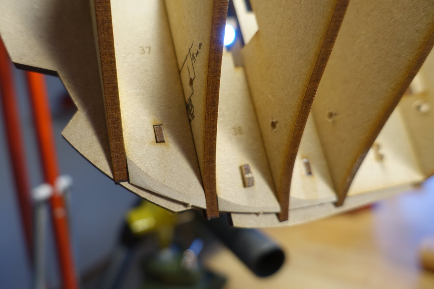
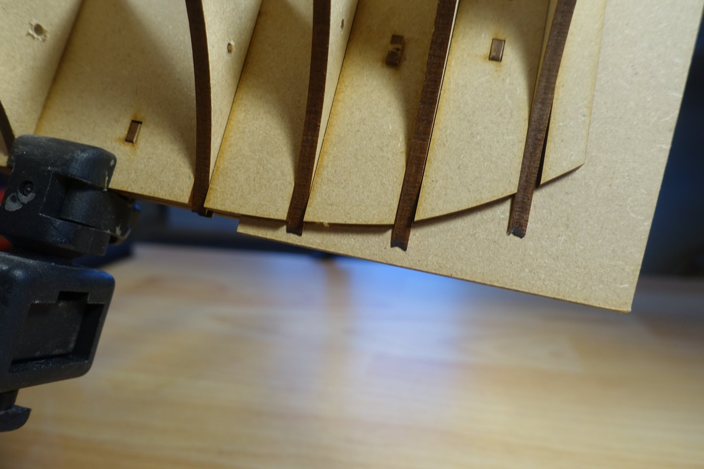
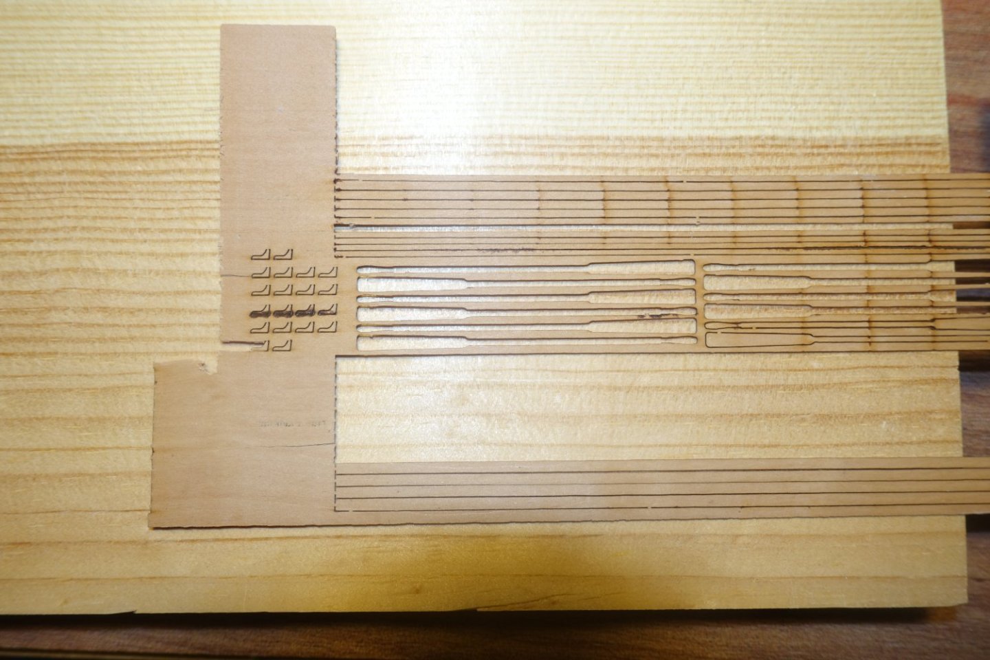
The deck was prepared for installation. First, I set the markings for the subsequent planking. I assumed that with a maximum plank length of 8 metres in the original at a scale of 1:64, the maximum plank length on the Indy is 125 millimetres. For easy calculation, I assumed 120 millimetres. Assuming that the planks were laid with a fourfold offset, a distance of 30 millimetres is necessary from offset to offset. In addition to the offset lines, I also added additional markings where the upper edges of relevant bulkheads run. This is for later mounting of the brackets for the Indie overhead. The deck was glued using the technique described by Blue Ensign in his Indy blog. . That means first one side was glued and then the other side. However, PVA glue was only applied in the middle area to begin with. For the outer area, the Indy was turned upside down and PVA was applied from below using a brush. However, a centre bridge broke off during attachment and was lost. In the picture you can also see that the lower deck half is displaced by about 0.3 to 0.5 millimetres. I checked the bow and stern again. However, the deck halves are exactly centred there. So I didn't correct them any further. The deck will also be planked, which will help to even out any such errors. I made a replacement for the missing centre bridge out of plywood Next, the horizontal gun port strips and the vertical frames were glued. The vertical frames are position-specific, but Chris marked them so precisely that you can't go wrong if you can read. This also further stabilises the bulkheads. When installing the stern frames, it was important to note that the LED cables would later have to pass through these frames. I therefore removed the vertical leg from the middle stern frame so that it would still be possible to feed the wires through the hole drilled in bulkhead 18. When positioning the poop deck beam ledges, I was afraid that there might be a little too much play at the stern. To align the ledges here, I therefore provisionally attached the deck beams of the deck and applied PVA glue moistly with a brush to the joints of the ledges. To sand the inner bulwark supports smooth, I laid the Indy on its side and fixed it in place with the help of the Amati apparatus. I sanded the bulwark supports and the vertical gun-port strips again with my sanding sticks. In the straight area, I essentially orientated myself on the bulkheads. These are ideally aligned, so that mainly the vertical gun-port strips were sanded into alignment. In the bow area, the orientation was based on the curved longitudinal strips for the gun ports. The result was checked with a thin strip. I also sanded the support structures of the rear cabin smooth at this stage. LEDs are to be installed here and it would be unfavourable to start the sanding process again after the LEDs have been installed. Before I fitted the inner bulwarks, I first constructed a bracket with which the Indy can be fixed overhead later when planking. A 10 millimetre dowel sanded at the side, was passed through the opening for the foremast. A 5 millimetre sheet with a walnut reinforcement was then used to further stabilise the dowel. The sheet was then fixed to the bulkheads below with screws. As the deck will be planked over later, the screw holes are harmless. A suitably prepared 12 mm dowel was passed through the opening for the main mast and stabilised accordingly. The Indy can later then be clamped into the AMATI holding device using the two dowels The inner bulwarks were first soaked with water, then clamped to the spars, left to dry overnight and glued with PVA glue the next day. In the picture you can also see a small protrusion of the aft bulwark near the deck compared to the bulwark laid in front of it. The projection is aligned from the other side with a small wood strip.


-
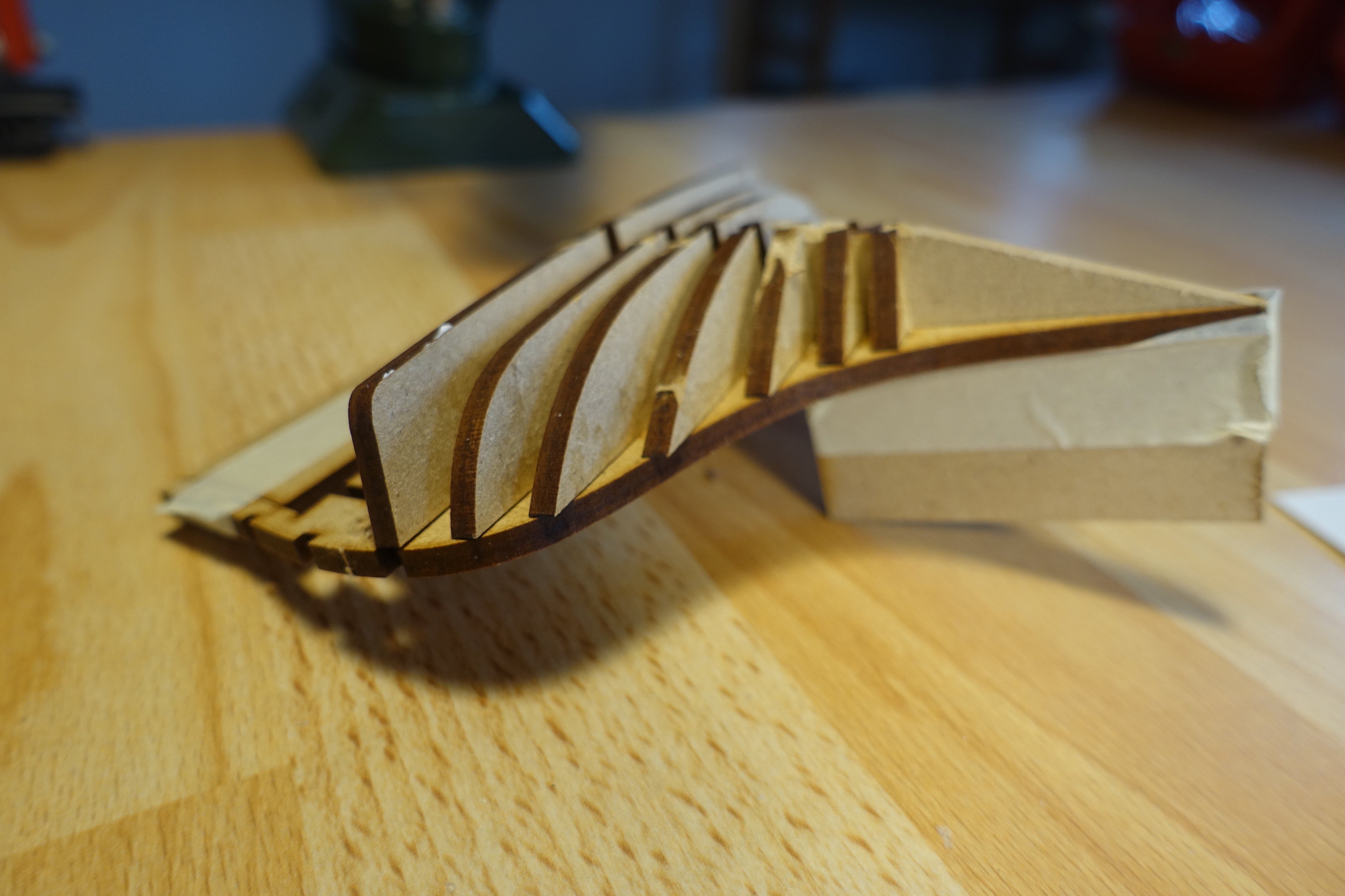
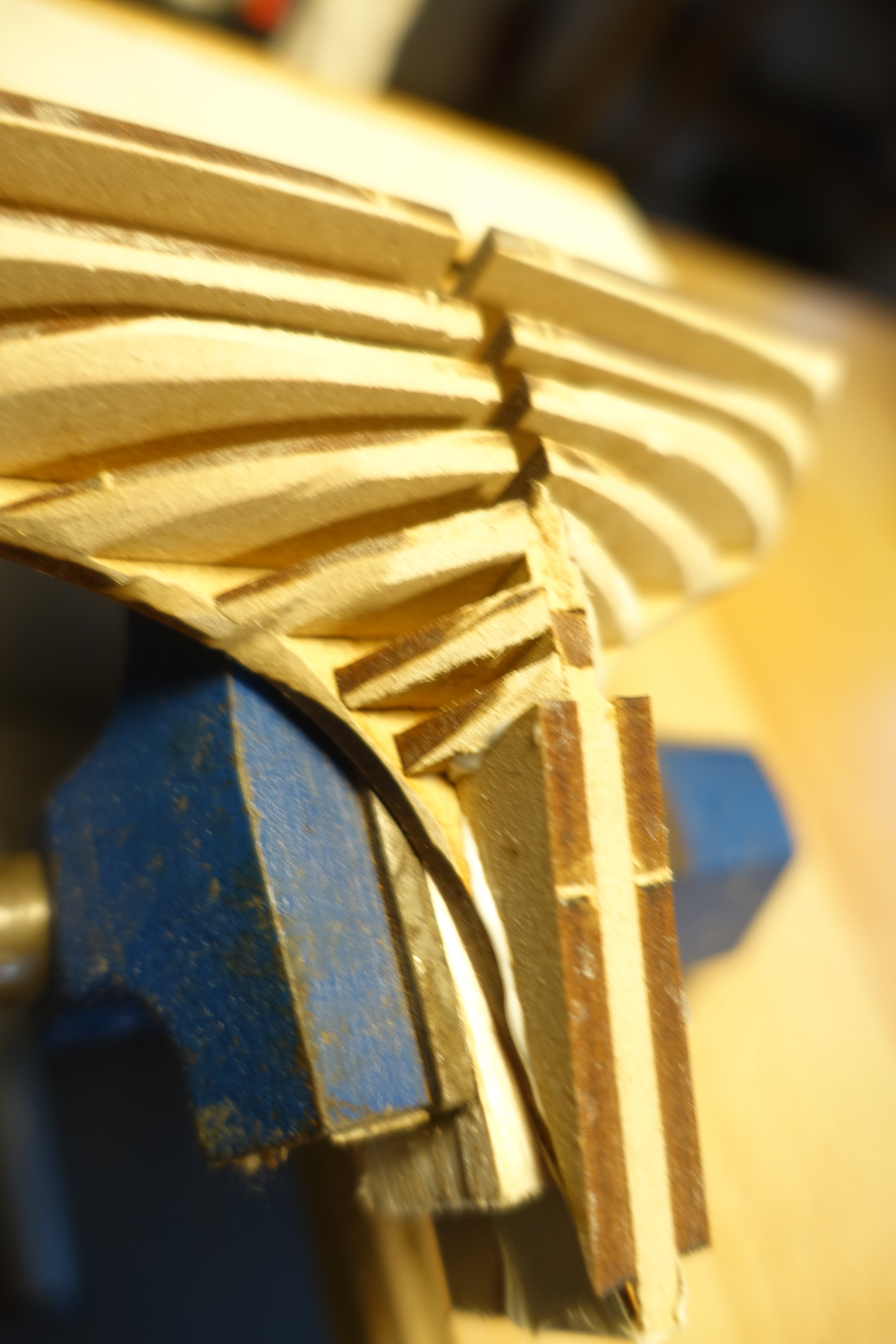
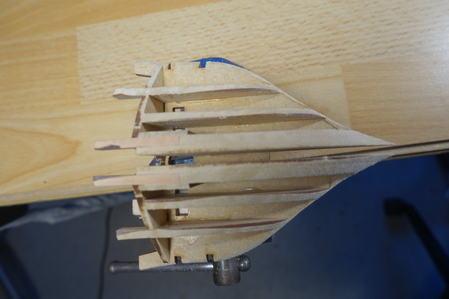
The longitudinal beams fitted well. In some places, light blows with a small hammer were necessary. When fitting the deck beams, I was initially surprised that 3 of the cut-out beams were left over. Here Chris probably thought that some might break. When sanding the bow and stern formers, the laser carbon can be used as a guide. Here I first sanded with a Dremel and then reworked with self made sanding sticks (80 and 120 grades) to work out the curvatures. The fillers for the stern area were glued into the last bulkhead, with a 4-millimetre MDF spacer used for the simulating the stern post. Everything fitted perfectly and no sanding was necessary. Congratulations, Chris. Contrary to the description in the building instructions, I also glued on the lower stern fillers (but not to the false keel) so that I could work on them. I found this easier to do outside the hull. I used a thin strip to check the shape. I also applied a little putty in the area of the lower stern filler to get a better idea of how the planking would go.


-
Hello Blue Ensign, Thank you for stopping by. So far, I have not worked with LEDs. I think I will have to try a few things when the build is more advanced. I will probably install the LEDs when the 3D puzzle phase (your term) is over. Clark
-
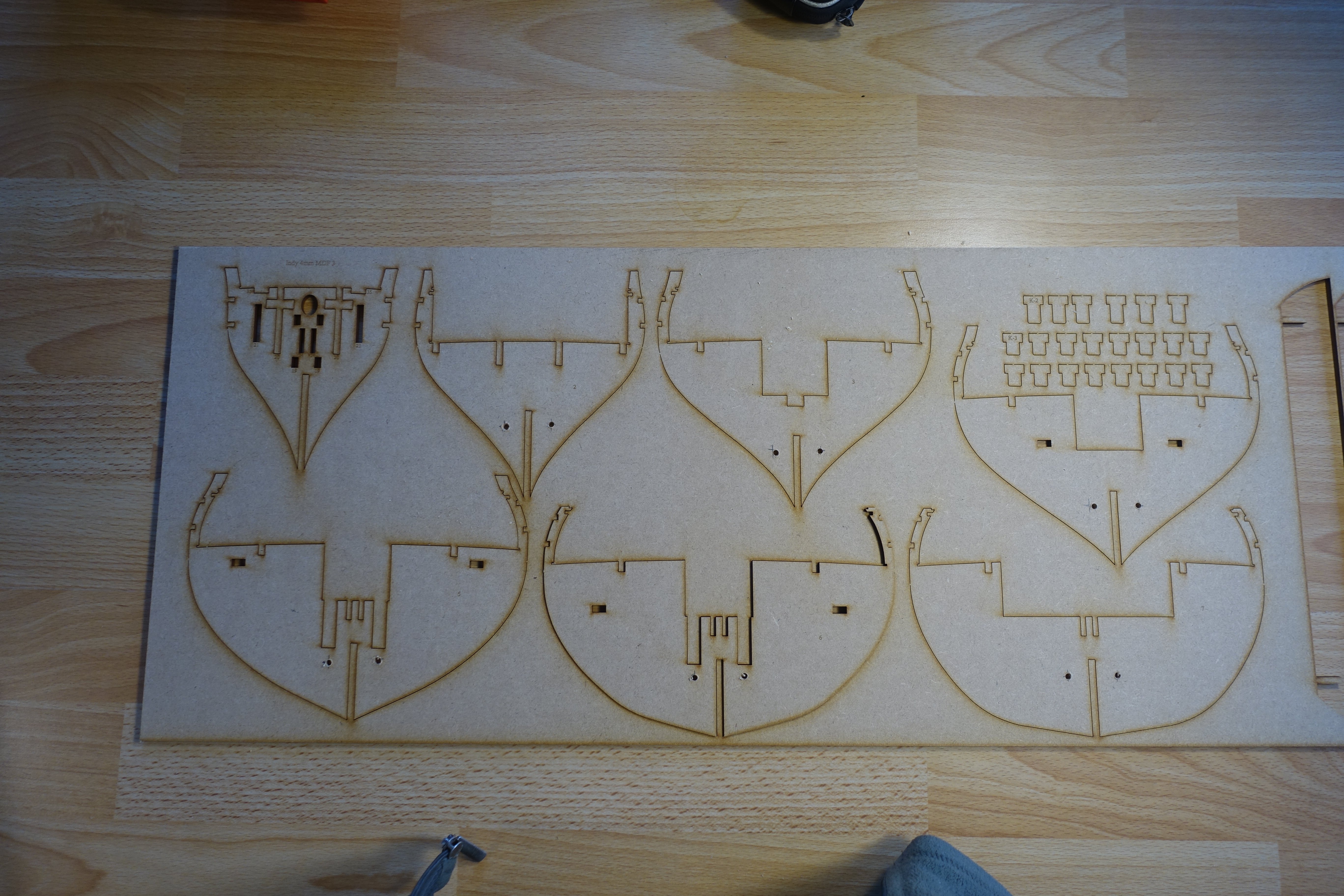
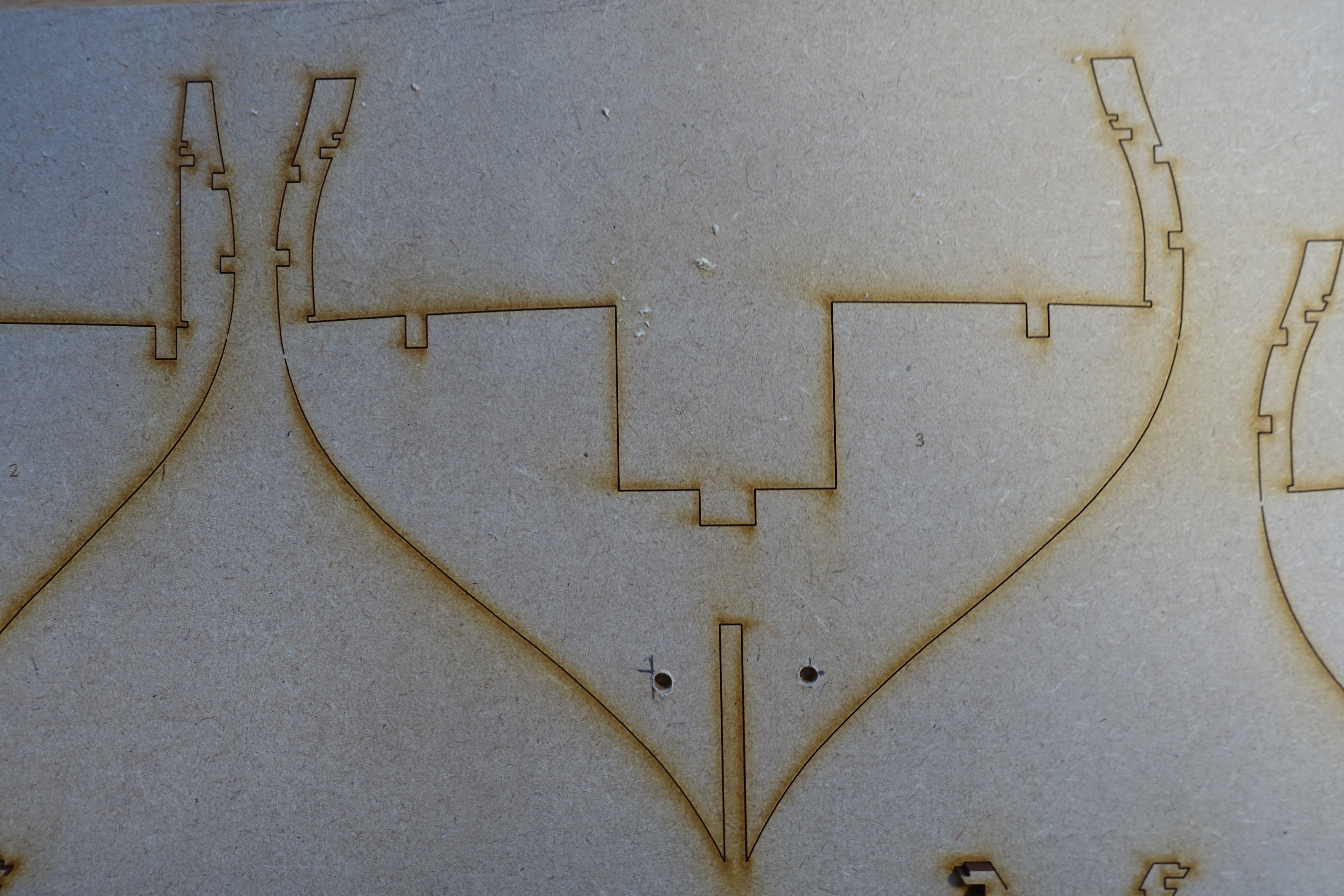
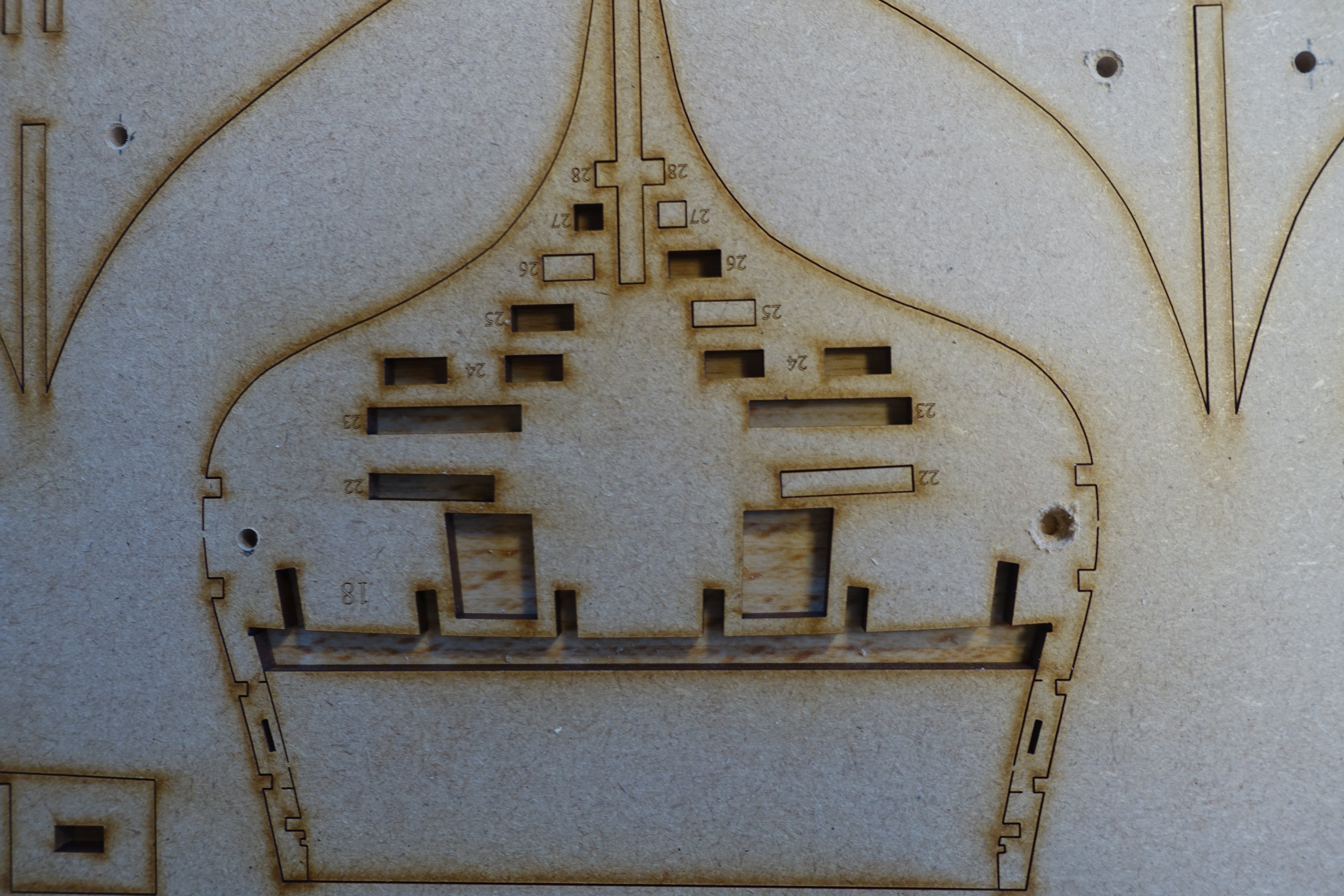
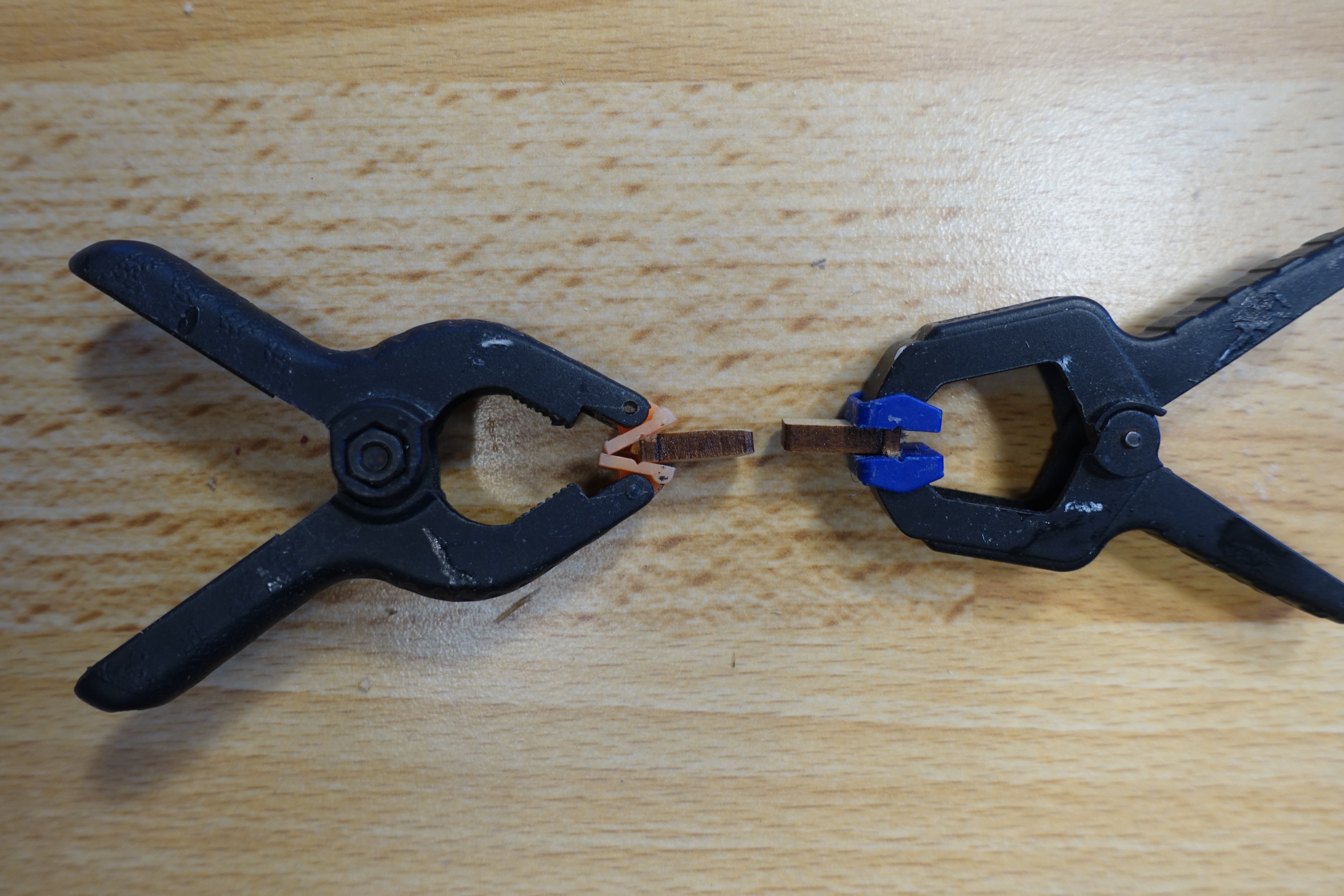
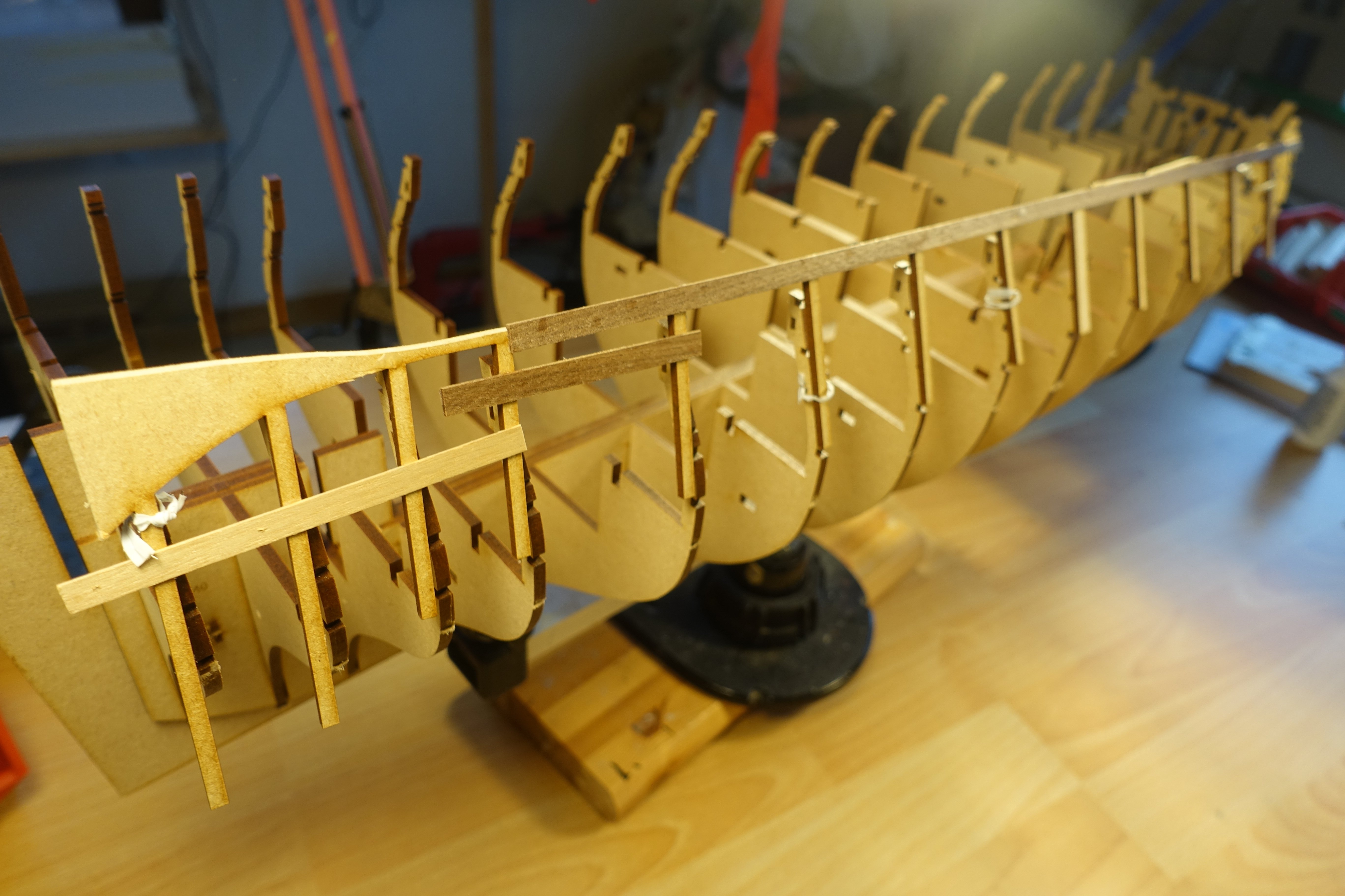
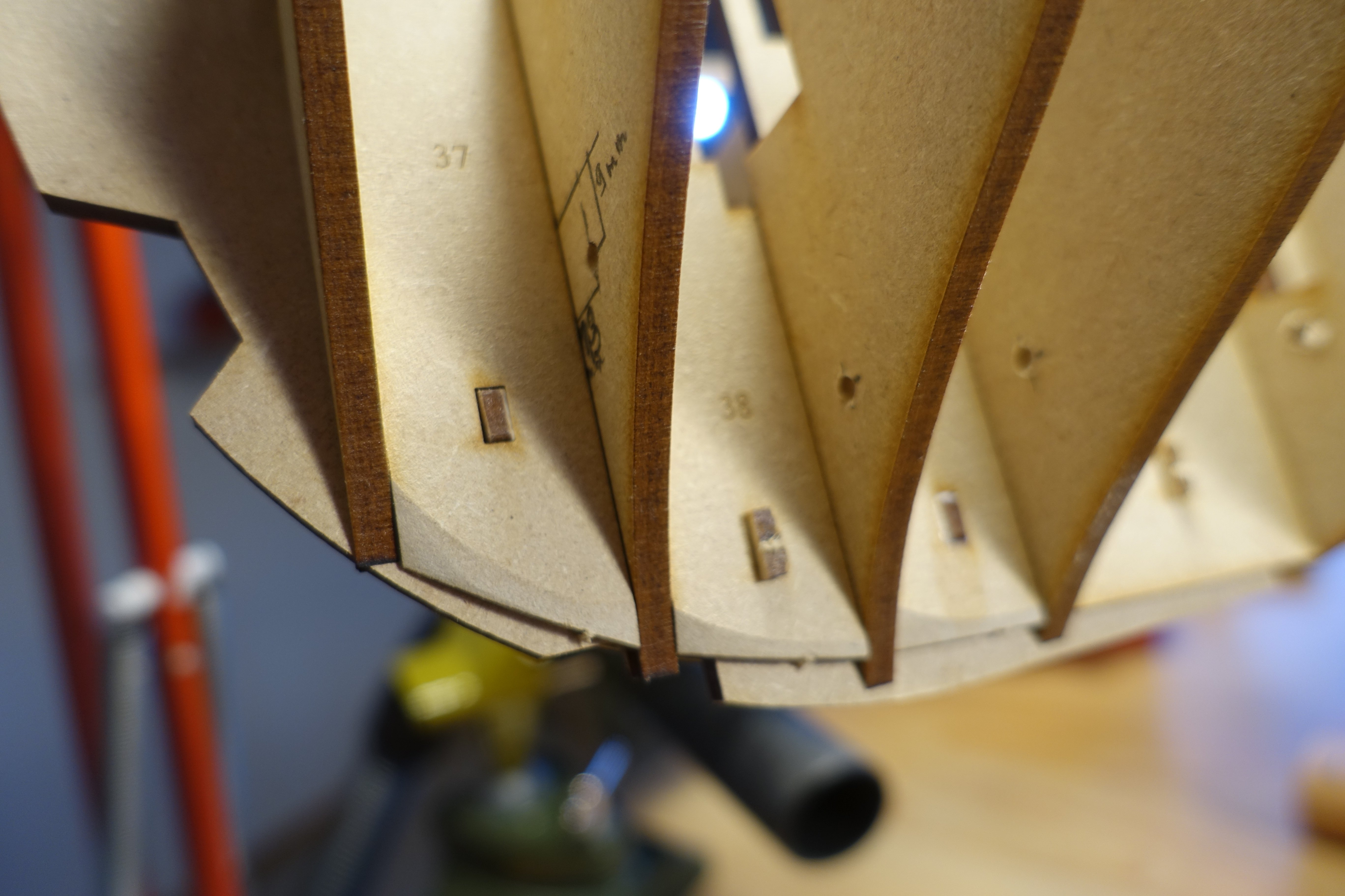
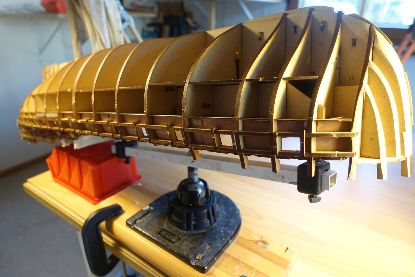
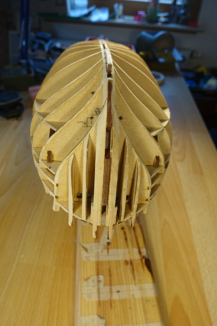
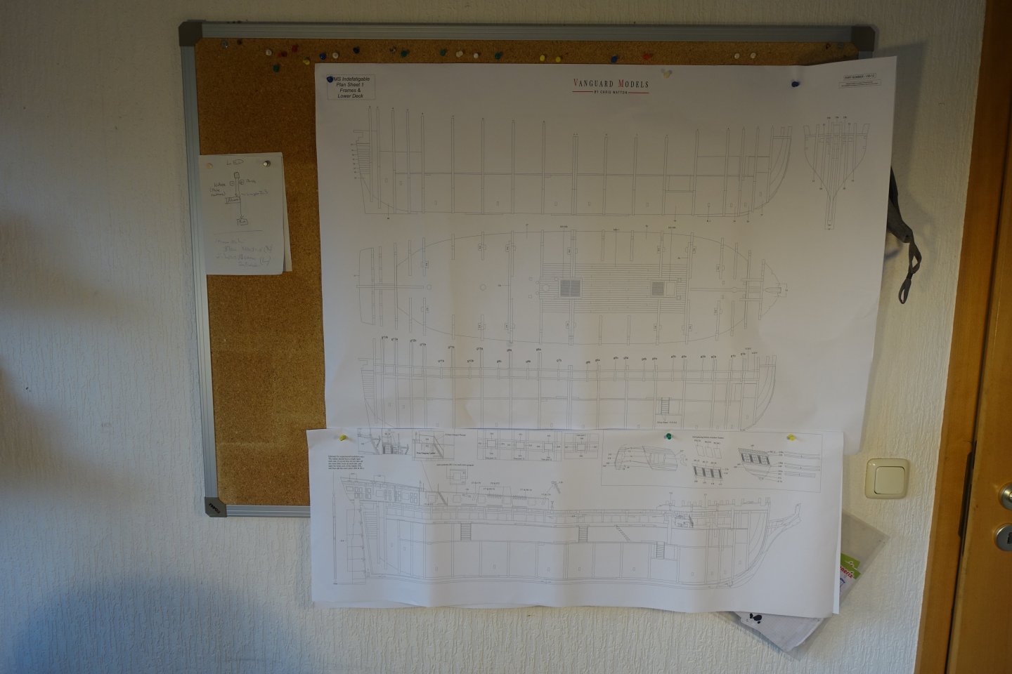
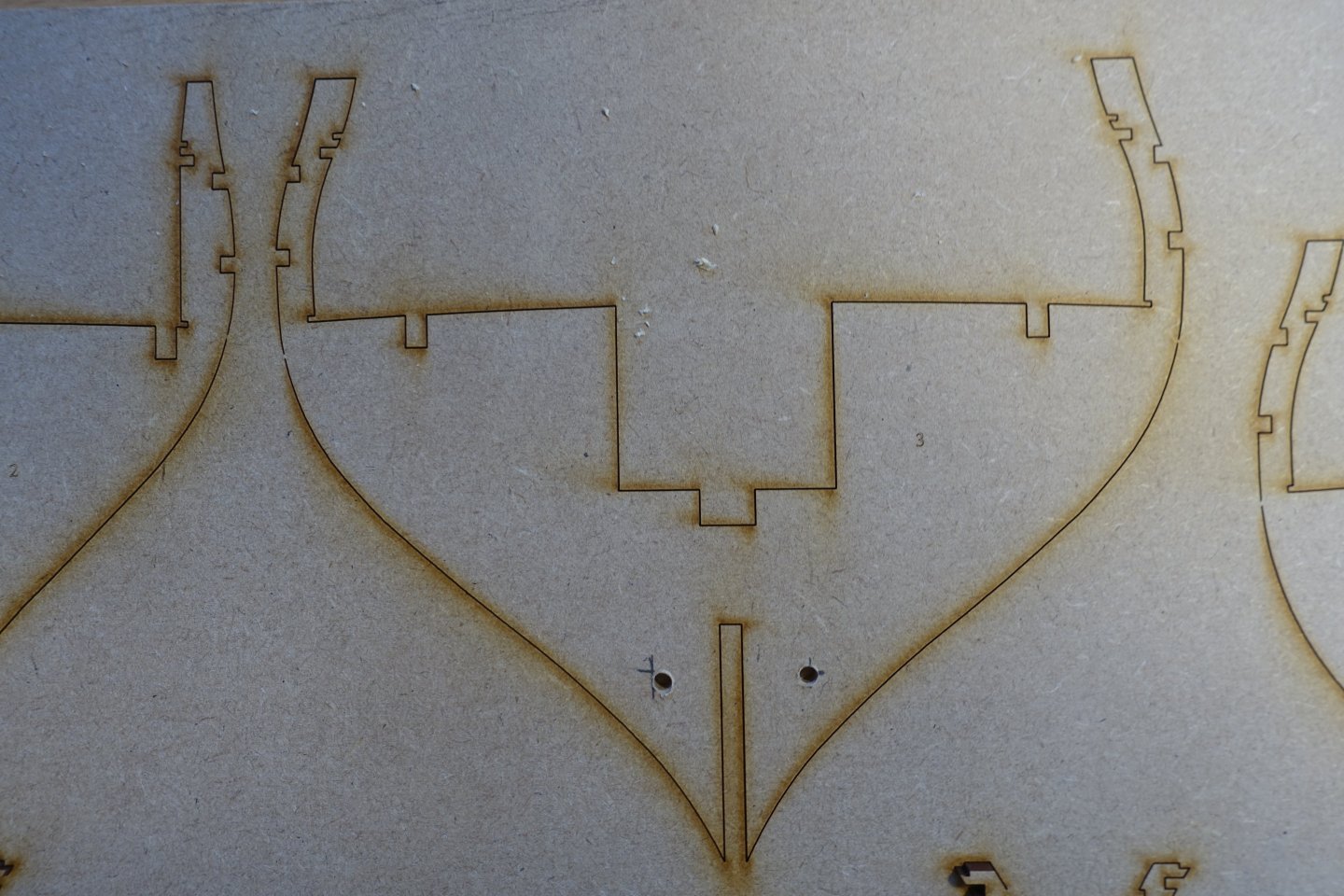
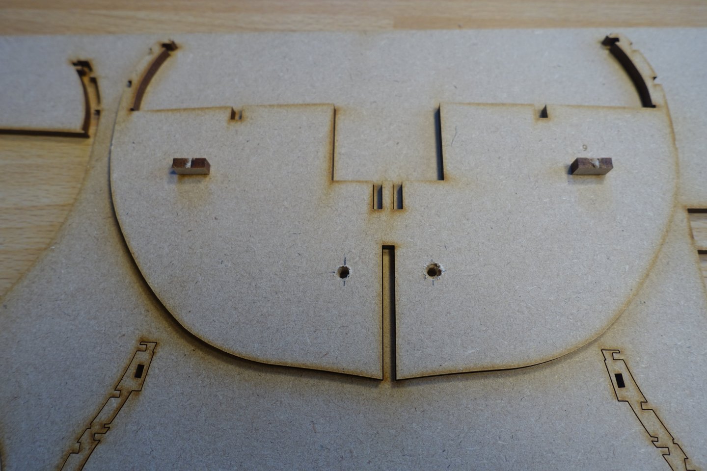
After I had finished the Sphinx, I wanted to continue with the Indy. There are good building reports on MSW. Therefore, I will mainly show what I will change compared to the building instructions. I was so sorry that you can't clearly see the lower decks on the Sphinx, even though Chris had planned some openings there. It's similar with the Indy. In my opinion, the openings through the decks are too small. I will therefore follow the approach of Blue Ensign. He has greatly expanded the breakthroughs through the upper decks. In addition, I plan to illuminate the lower decks with a few LEDs. First of all, I had to choose the LEDs. There are now countless variants available, all of which have their advantages and disadvantages. I decided on 3-millimetre LEDs in ultra-bright yellow diffuse (1600 mcd, 1.9V, 20mA) and ultra-bright warm white diffuse (2800 mcd, 3.3V, 20mA). To avoid having to rely on batteries, I also purchased an LED driver (12-volt DC output). The yellow LEDs then require a resistance of 510 ohms, while the white ones require a resistance of 470 ohms. Then I tried it out to see if it would work at all. Then came the early Christmas and I unpacked the Indie. First of all, I was amazed at the size of the Indy. This is also described in the other blogs, but when you see it in front of you, you are initially blown away. So there should not only be room for the Indy, but also for the associated plans. The next step was to think about the routing of the wiring. In the middle of the hull, this is certainly not a problem. The problem is the LED wiring under the poop deck. To get a first idea of how the wiring should run, I made a rough drawing. Holes were drilled in the bulkheads on both sides. For the double bulkhead 9, the two individual bulkheads were aligned using the keys supplied in the kit and then the holes were drilled accordingly. The wiring in the rear area had to be routed slightly differently so that the rear bulkheads had their outlets drilled higher up. I hope that the wires can then run accordingly later. The bulkheads were inserted and fixed with the holders. Here, too, I was amazed by the precise work of Chris. No reworking, let alone major filing, was necessary. Only the pegs were a bit difficult to push in, so I bevelled them a bit for better guidance. The bevel was only made on the front and rear side of the pegs. At the bottom left of the picture is a bevelled peg and on the right is a peg before the bevel. The bulkhead ears protrude quite a bit, especially in the rear area. I am therefore very afraid of breaking them off and have constructed a provisional railing for them. I used the leftover material from the MDF sheet in which the bulkheads frames were in. The fillers for the bow were slightly bevelled. I have not yet done this at the stern because I want to see how the planking at the stern will be done later. I did not modify the deck planking any further. The same applies to the hatches and the openings of the companionways. These areas of the deck will hardly be visible. To glue the steps of the ladder, I used a right angle and held it against a piece of balsa wood that was fixed with pins.


-
Can you already estimate when you will put the sheets up for sale.
-
Congratulations B.E. Perfect like all your models
- 131 replies
-
- 1
-

-
- Medway Longboat
- Syren Ship Model Company
- (and 1 more)
-
When completing my model, I was also unsettled by the illogical rope guidance. It's nice to know that others feel the same way. It would make sense if the horse ran over the tiller but not below. Has anyone seen that before? Clark
-
Hope you feel better soon and can return to the shipyard.
- 426 replies
-
- 1
-

-
- Vanguard Models
- Sphinx
- (and 1 more)
-
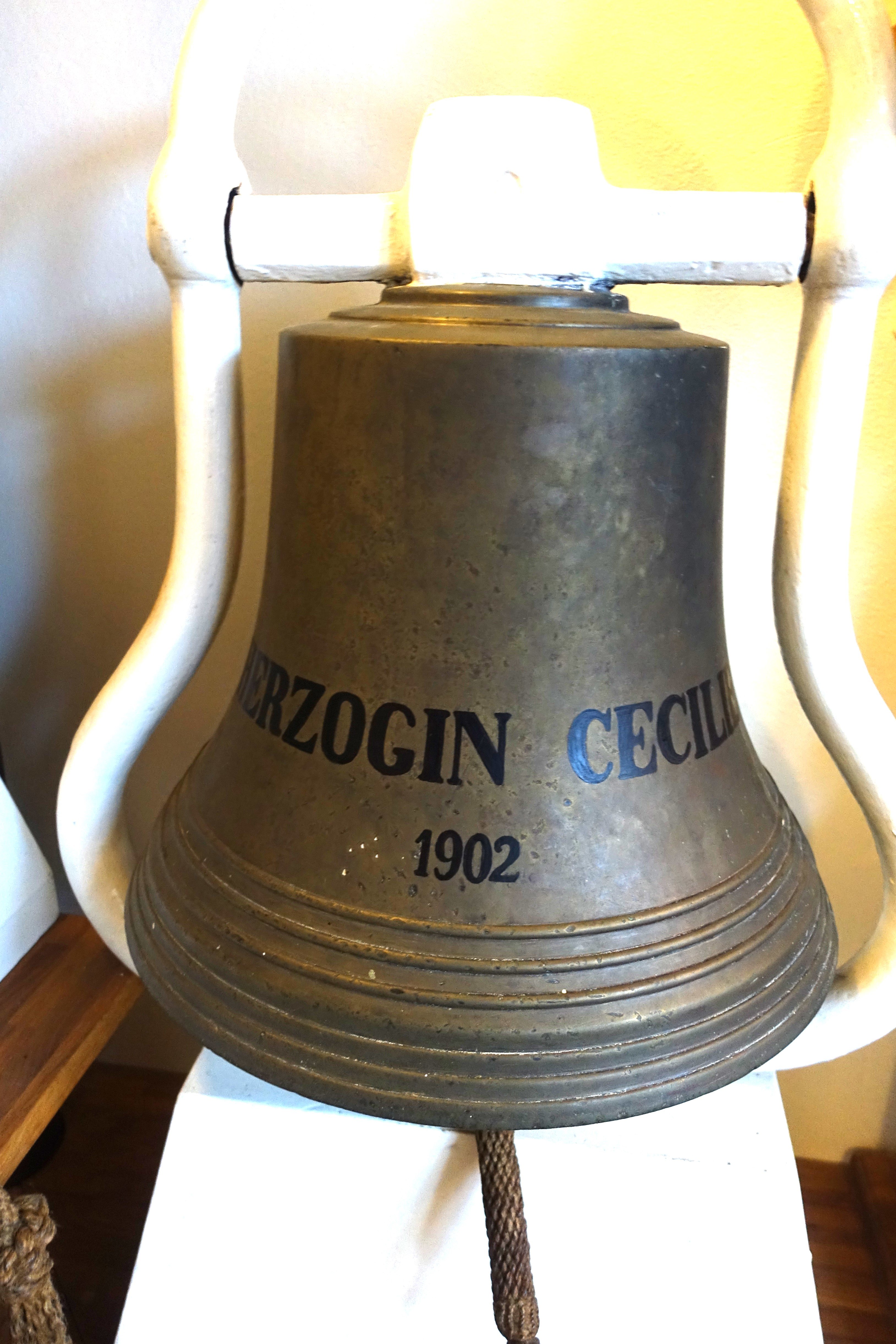
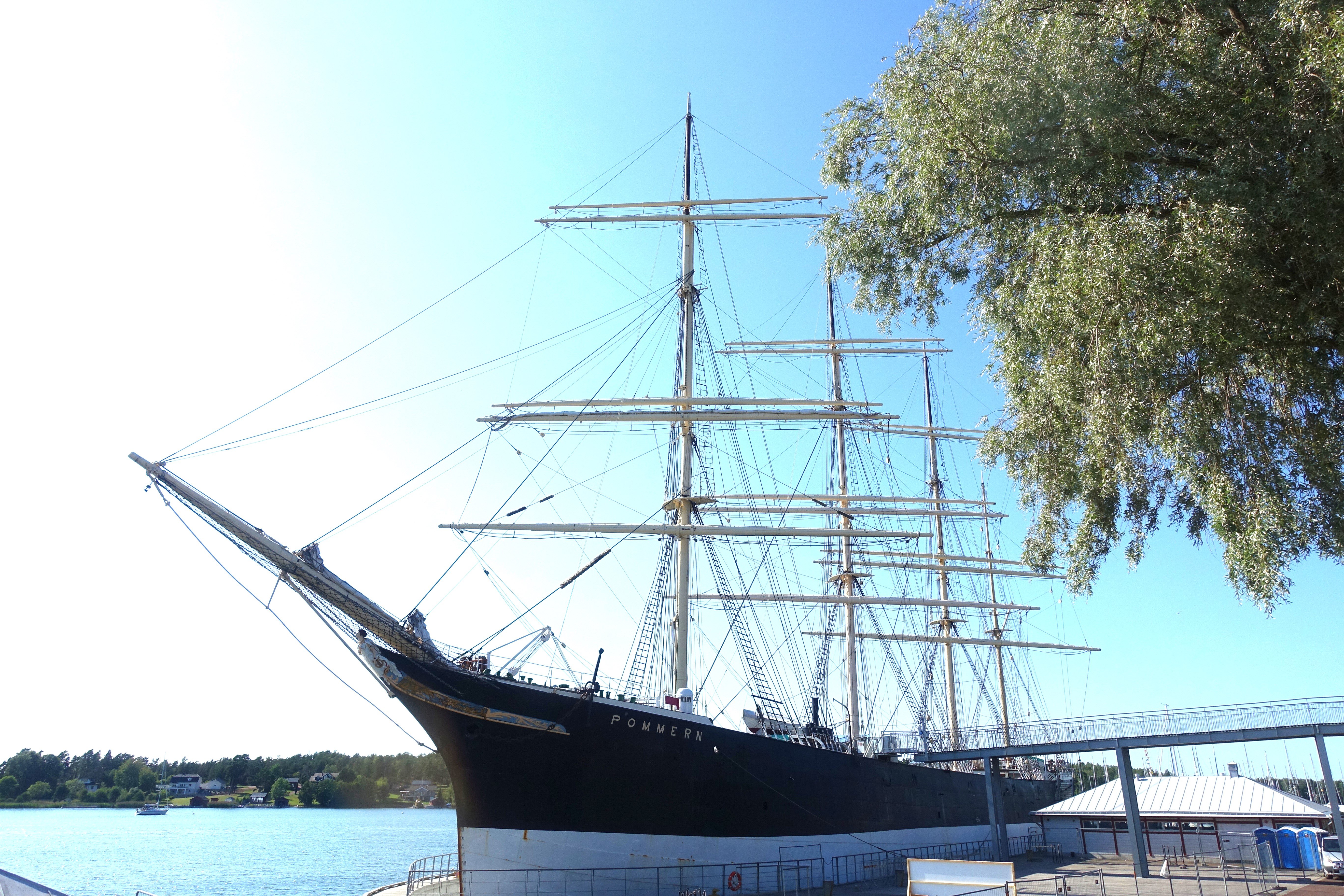
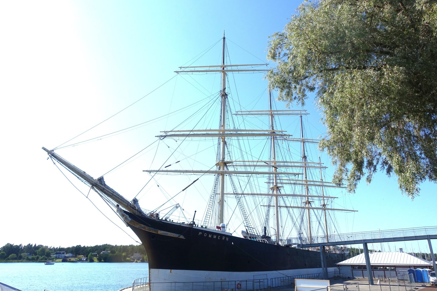
I was very pleased to see Duchess Cecilie again. Four weeks ago, I had just been to the Maritime Museum in Mariehamn. It's well worth a visit, as the history of Gustav Erikson and Duchess Cecilie is presented there in detail. You can also see the last four-masted barque in its original condition, the Pommern (formerly Mneme). It is well worth a visit, especially as the Alands themselves are well worth a visit. Enclosed is a photo of the bell of the Cecilie and a photo of the Pommern.

-
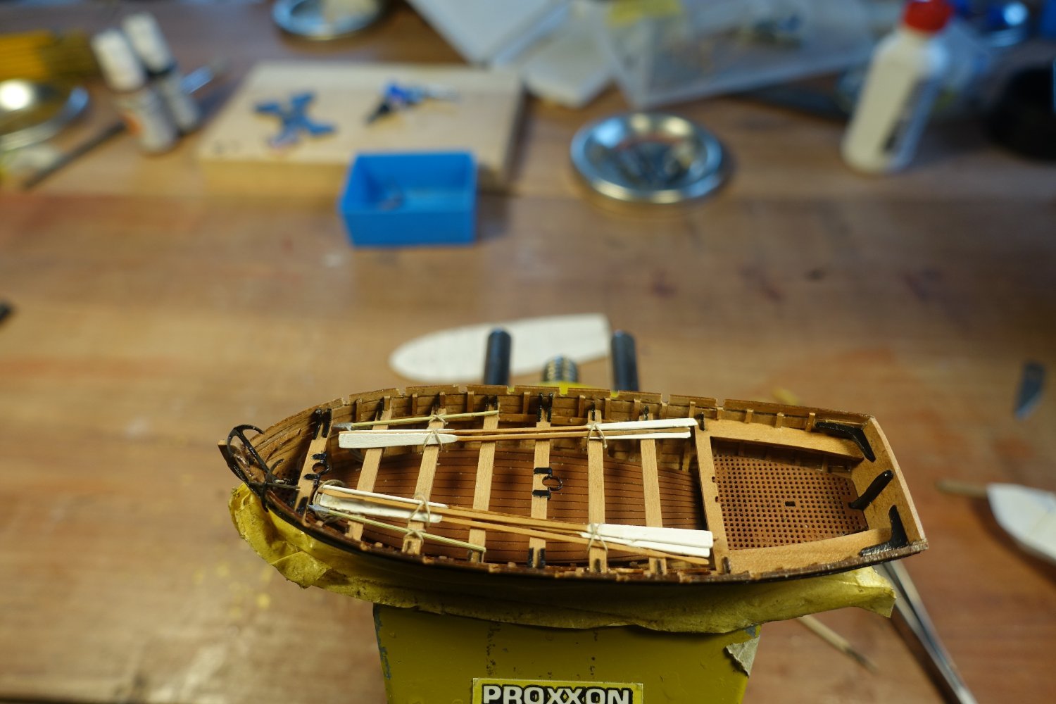
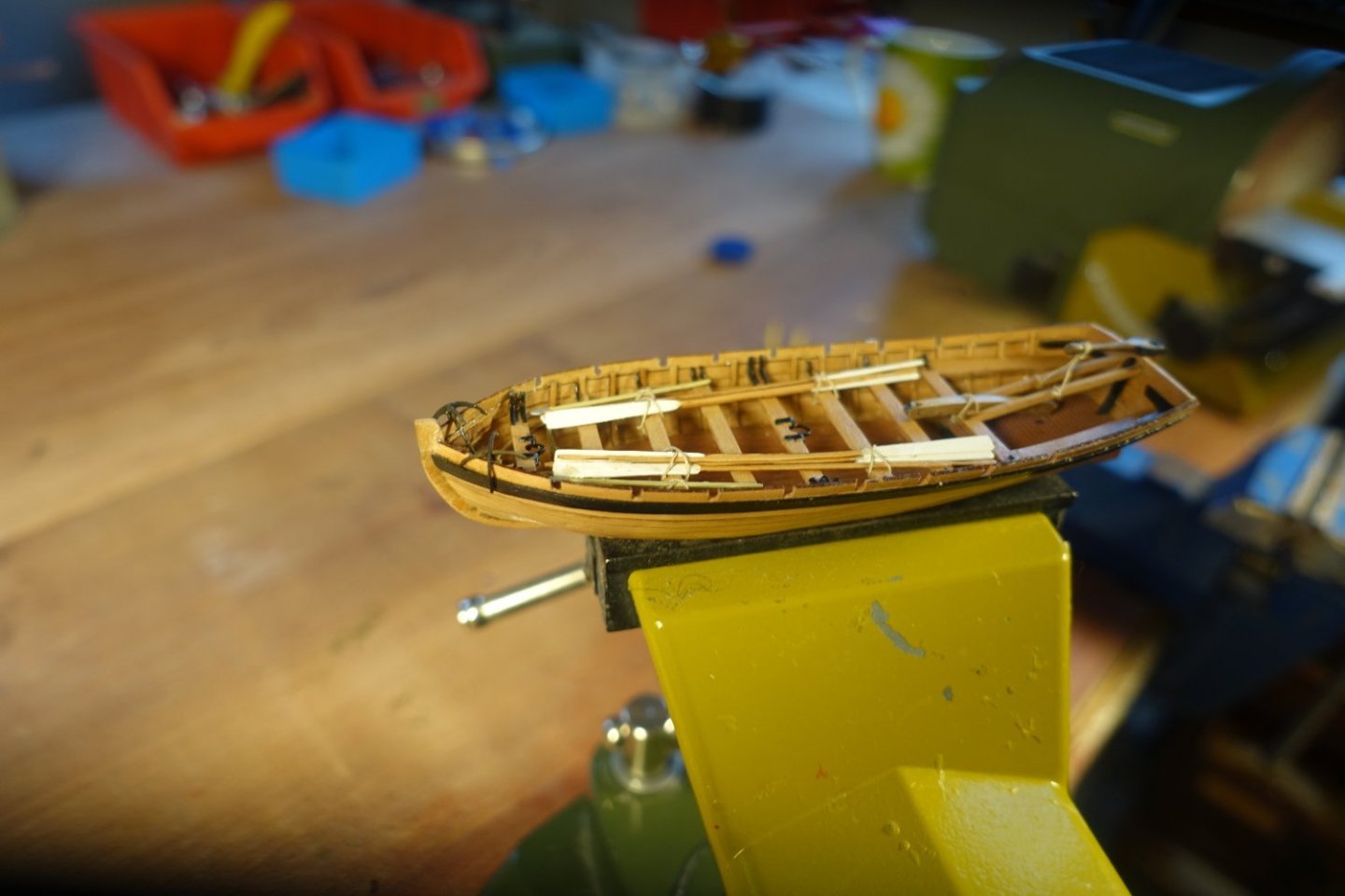
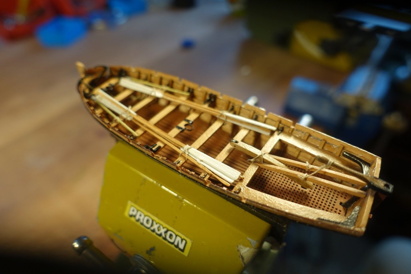
The boat is ready and waiting to be lashed to the Sphinx. I hope that this report will encourage some people to build these nice little boats. After all, they take up very little space,


- 22 replies
-
- 8
-
-
- 24 ft Launch
- Vanguard Models
- (and 1 more)
-
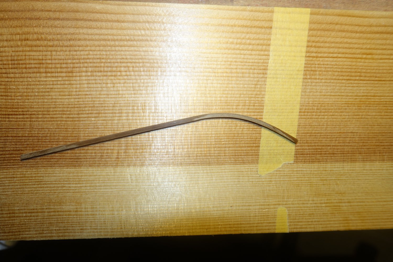
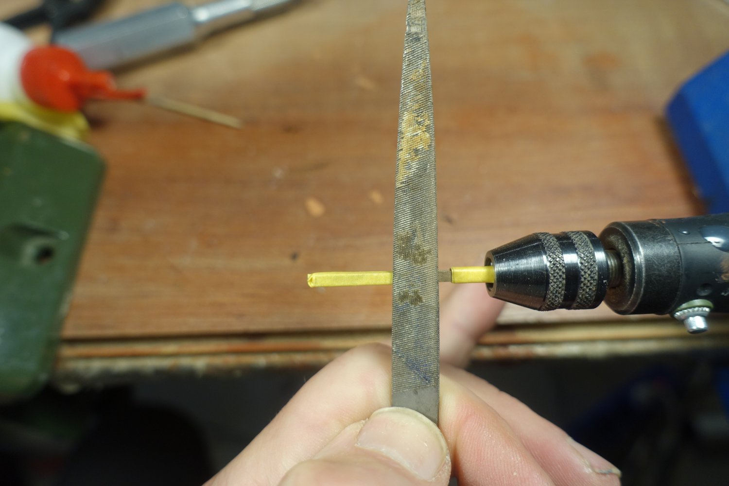
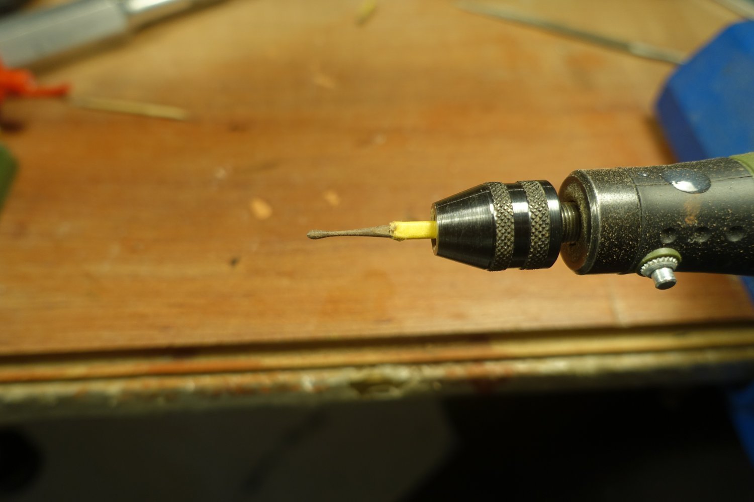
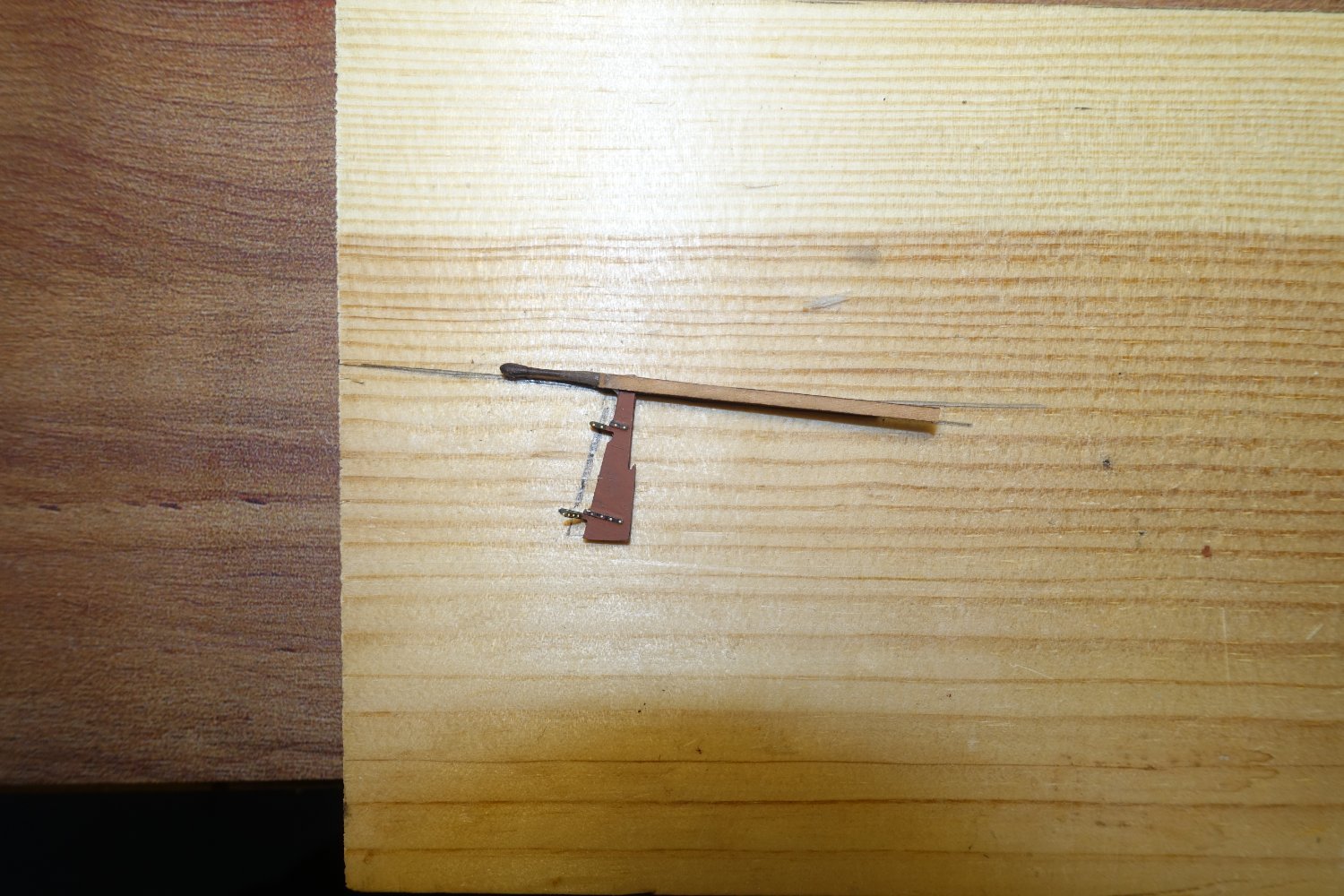
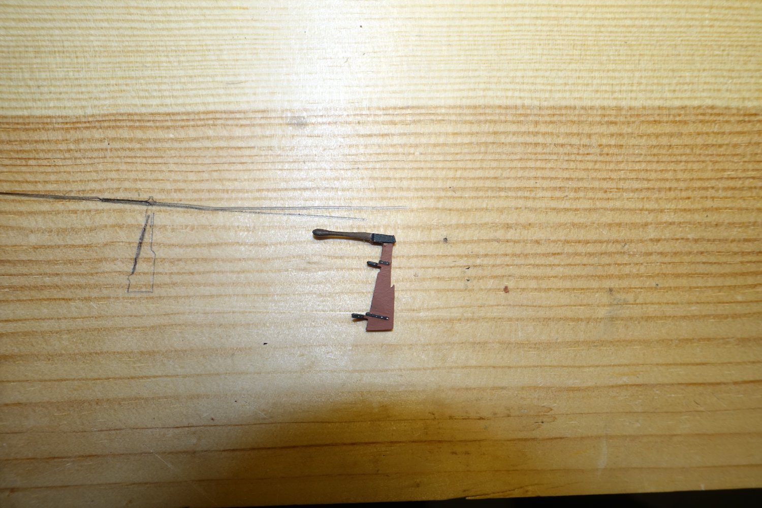
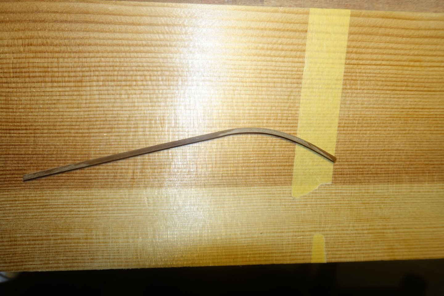
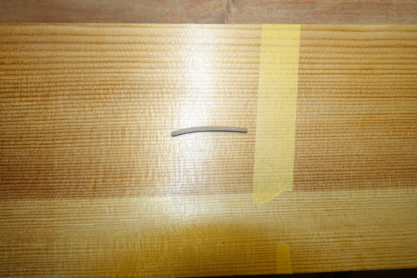
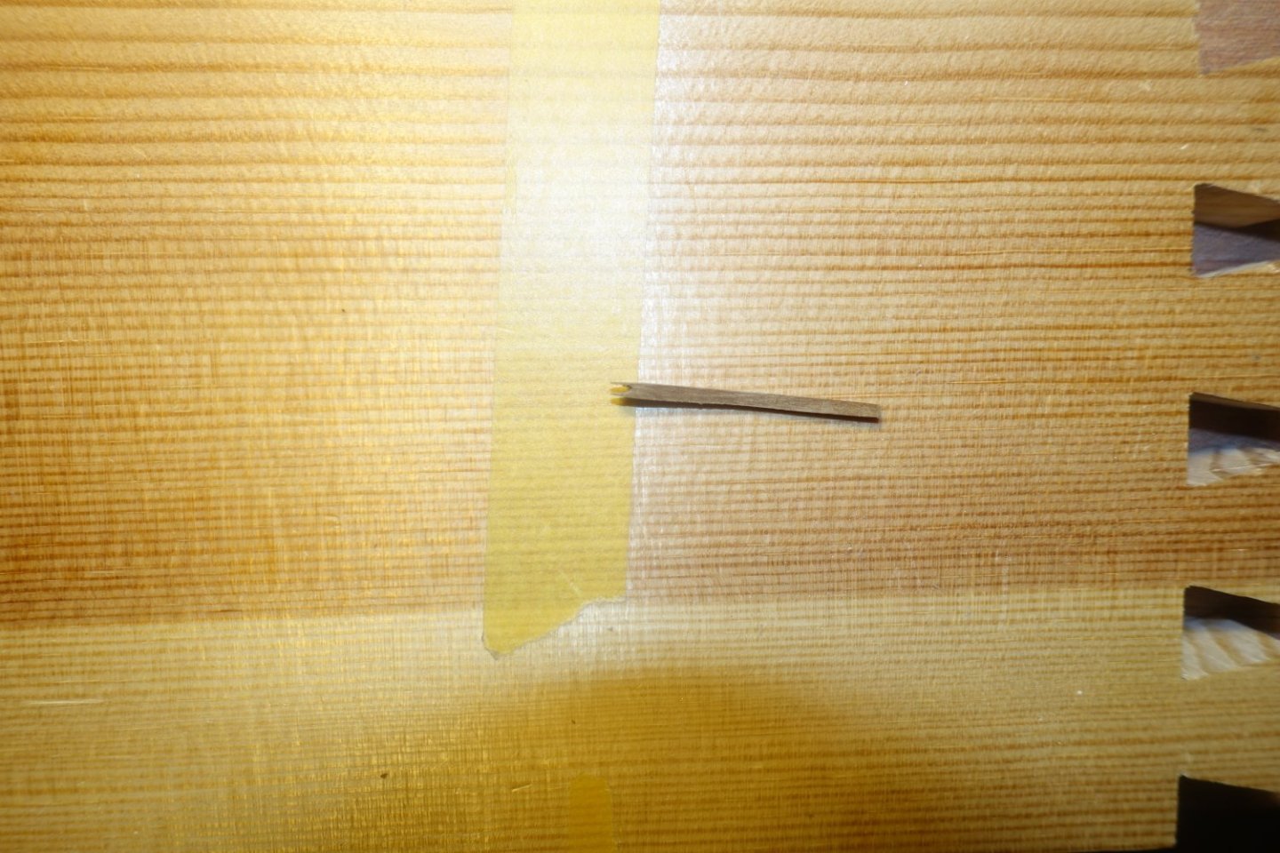
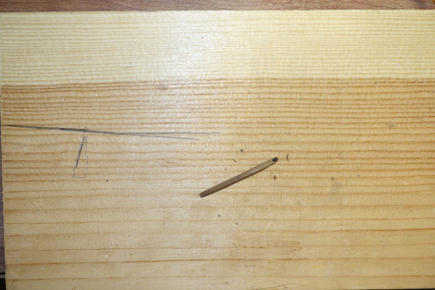
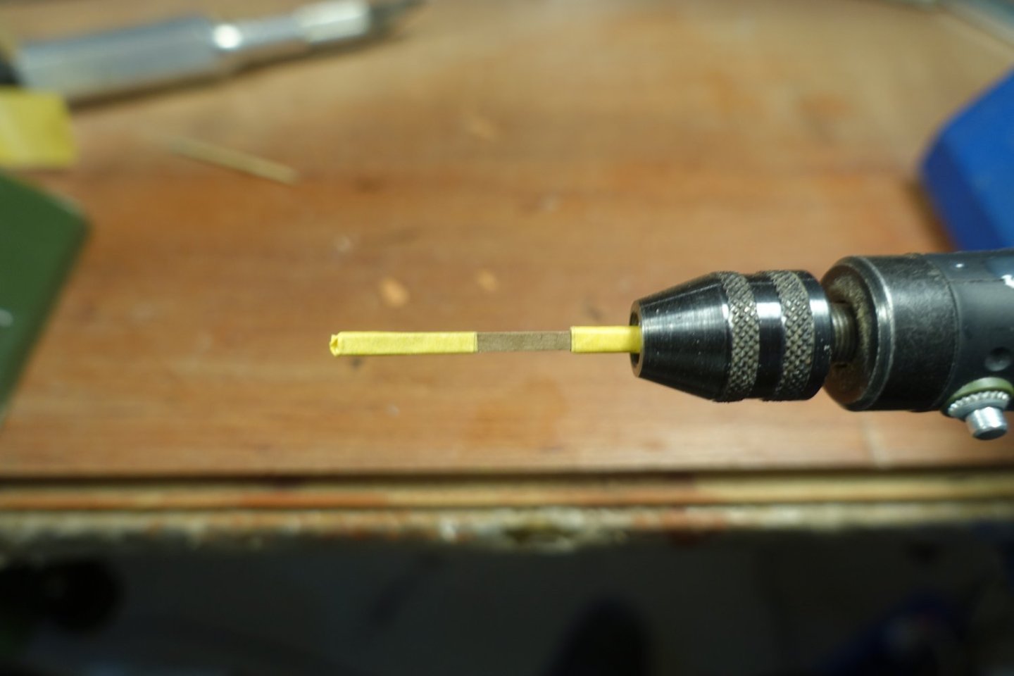
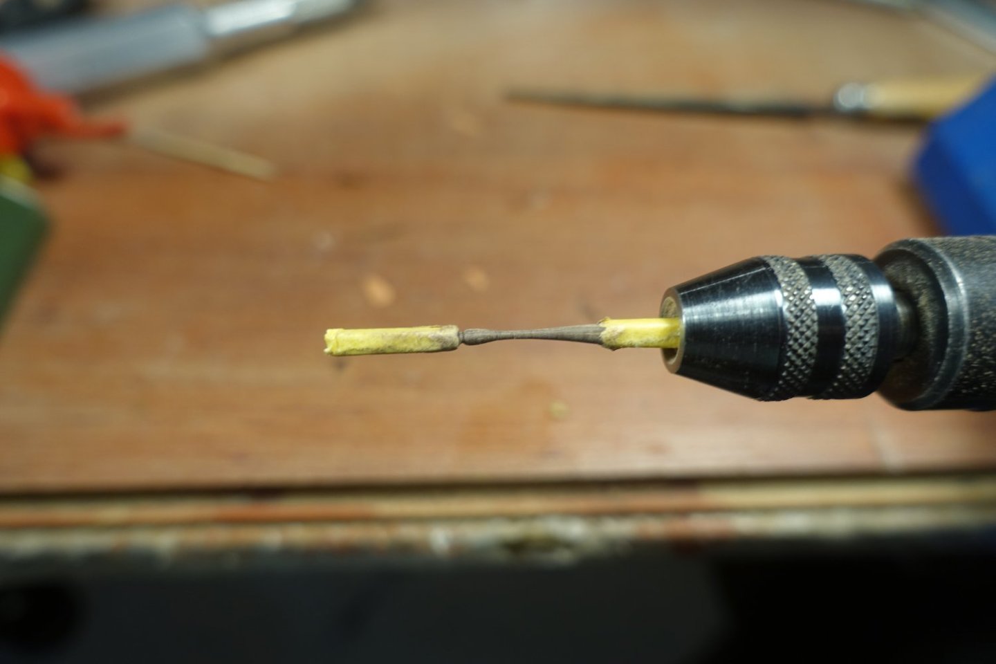
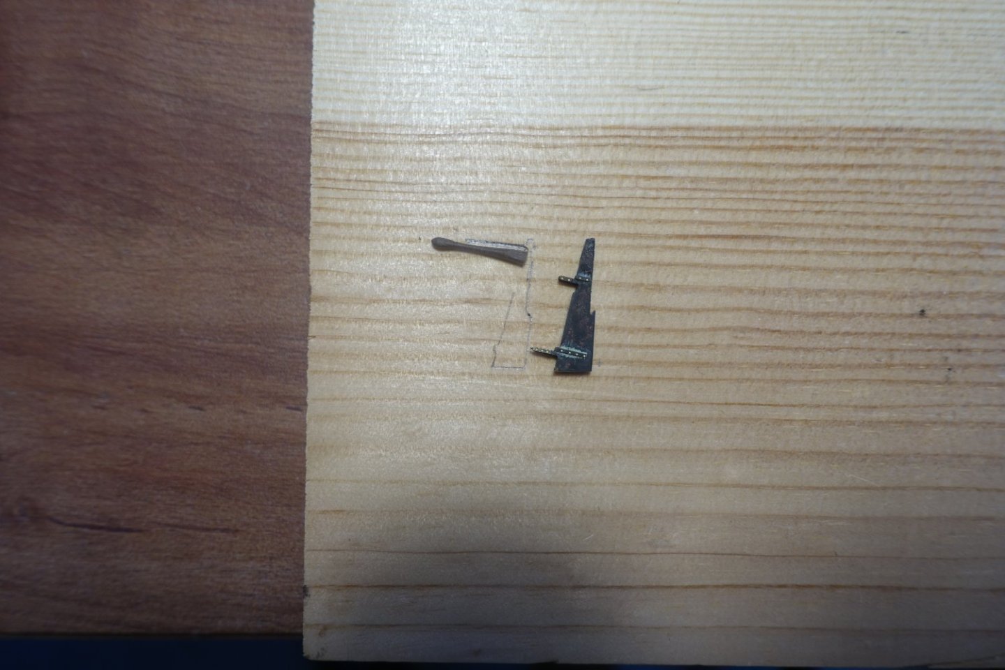
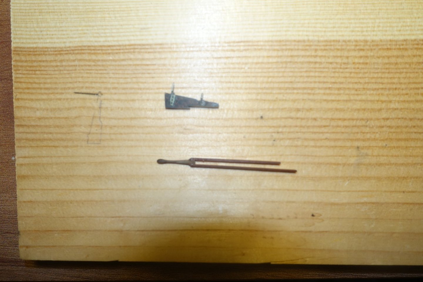
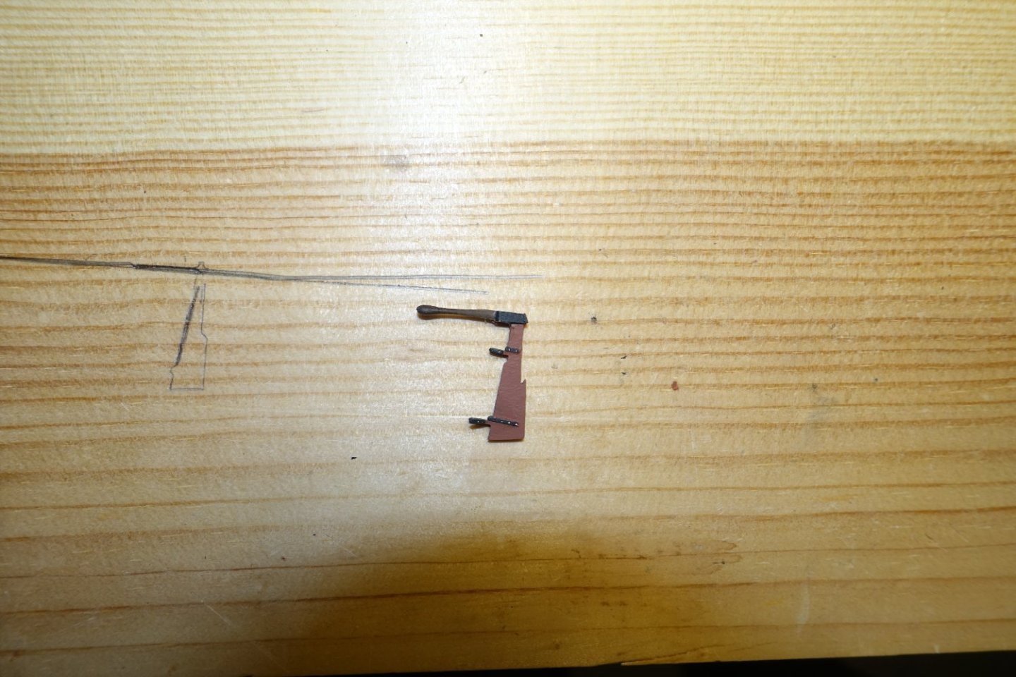
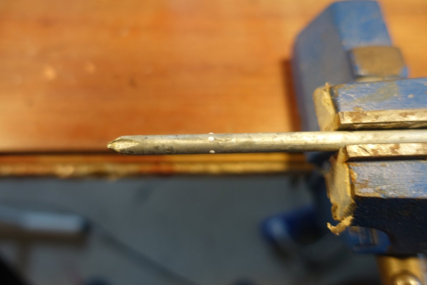
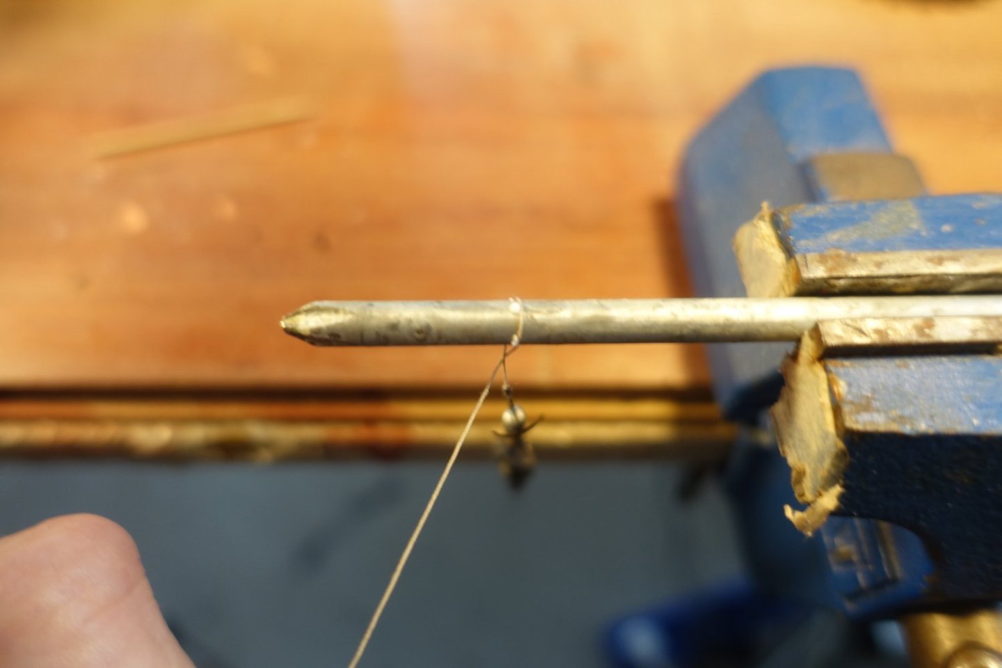
Davit and rudder I didn't quite like the davit from the kit, since it seemed to fragile. So I bent a 2 x 2 mm strip and sanded it to size. Davit with brass rod " sheave ". I made a rudder tiller from a 2x2mm strip, which I sanded accordingly The tiller was filed to the width of the rudder and the bevel adjusted. In the picture, the brass rudder cover has already been treated with a blackening solution acting quickly. Two remaining pieces of the sit support strips were glued to the sides of the tiller Once dry, the rudder was fitted in the strips. A transverse strip was added at the back, the rudder was painted with mahogany wood paint, the rudder hinges and the tiller hinge black. Rudder and davit are attached and secured.


- 22 replies
-
- 3
-
-
- 24 ft Launch
- Vanguard Models
- (and 1 more)
-
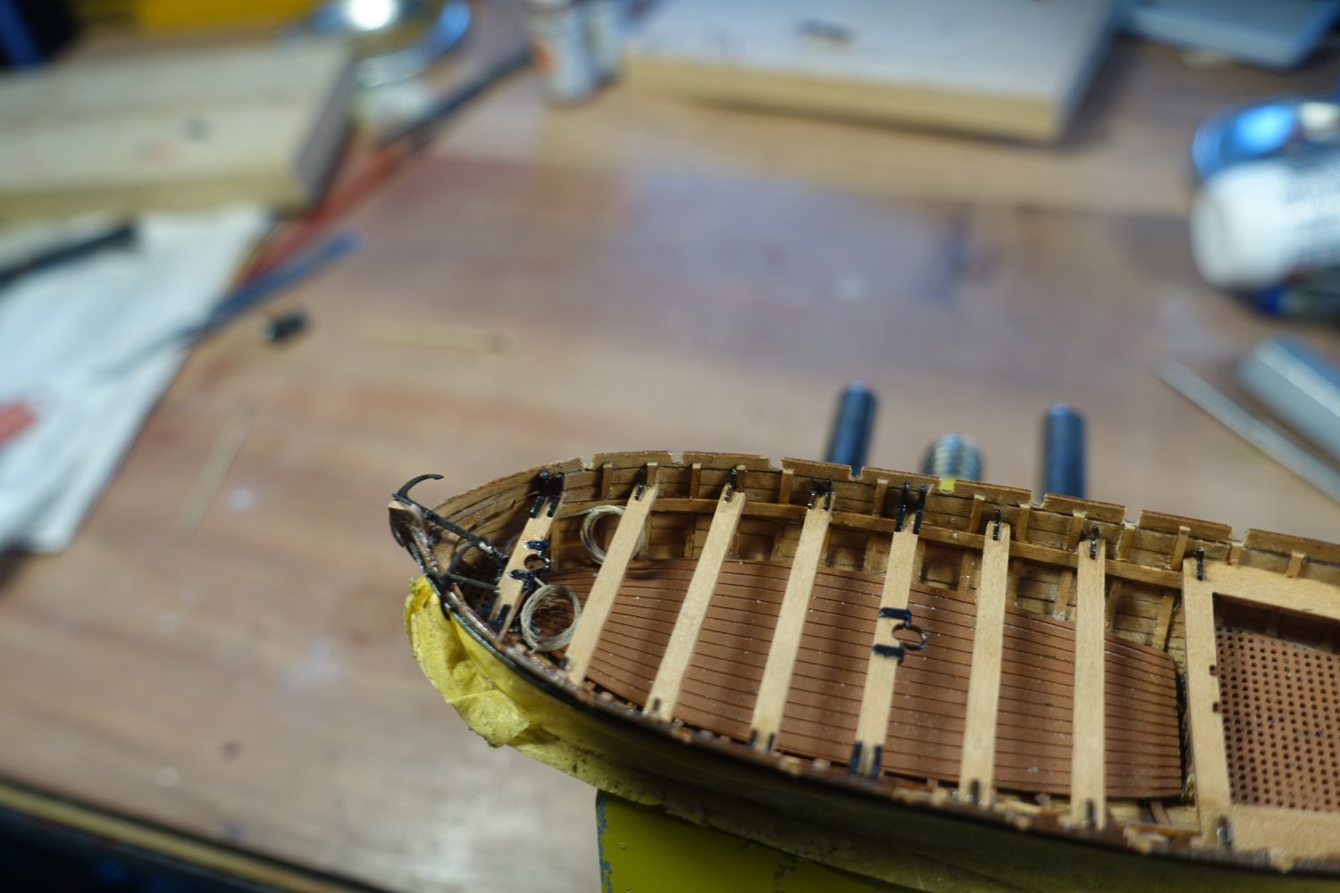
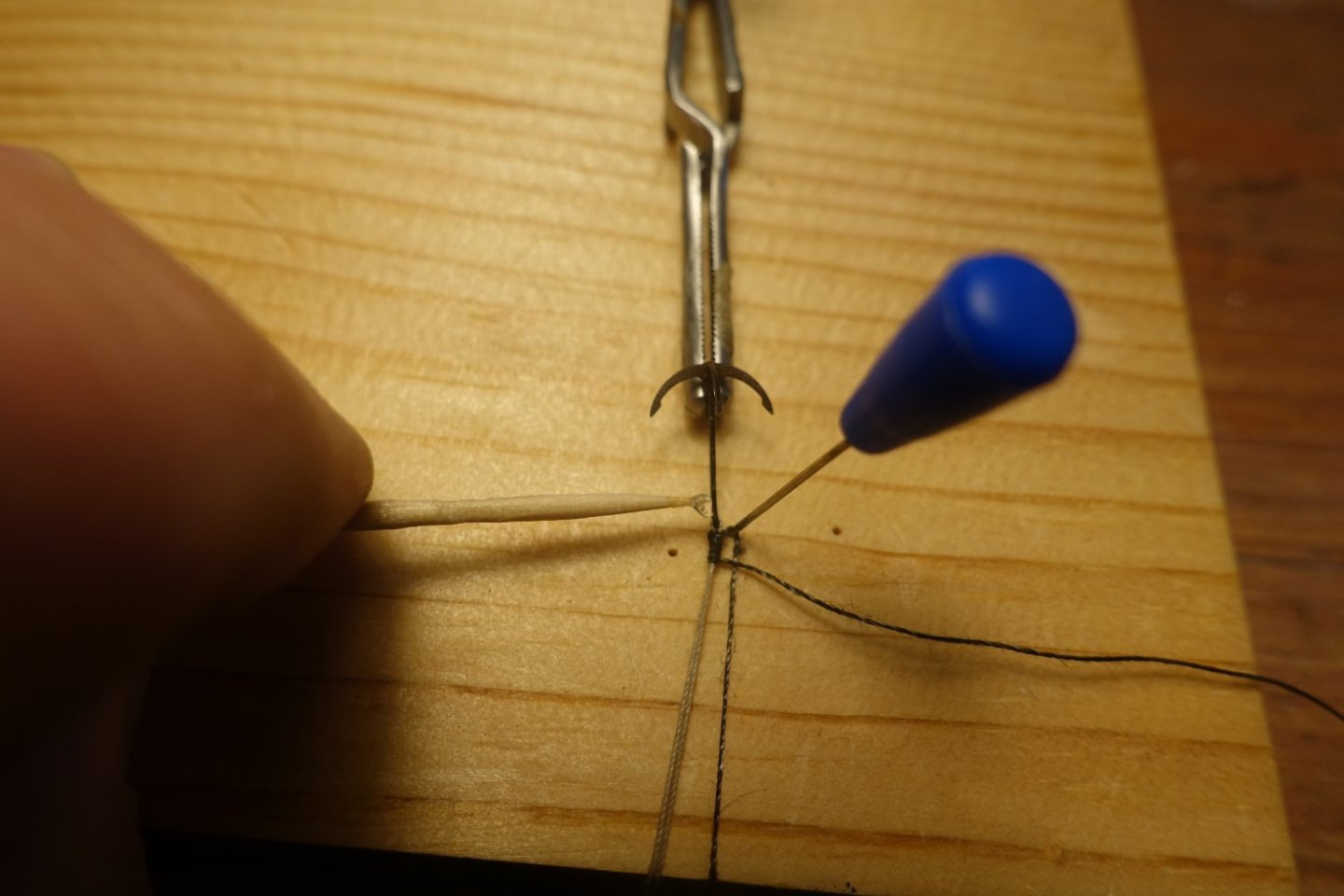
Anchors, oars and hooks Anchors were supplied with a rope. I used a screwdriver to roll up the anchor rope, put some PVA on the rod and then wrapped the anchor rope around it. The anchors were stored in the bow area. Oars and grappling hooks were secured on the thwarts.


- 22 replies
-
- 2
-
-
- 24 ft Launch
- Vanguard Models
- (and 1 more)
-
Gunwale and rubbing strake The gunwale was glued on with PVA (attachment to the bow: CA). The slightly protruding ribs made it easy to align it with the lower hull wall. The recesses for the oars were sanded in. The rubbing strakes were fitted.
- 22 replies
-
- 1
-
-
- 24 ft Launch
- Vanguard Models
- (and 1 more)
-
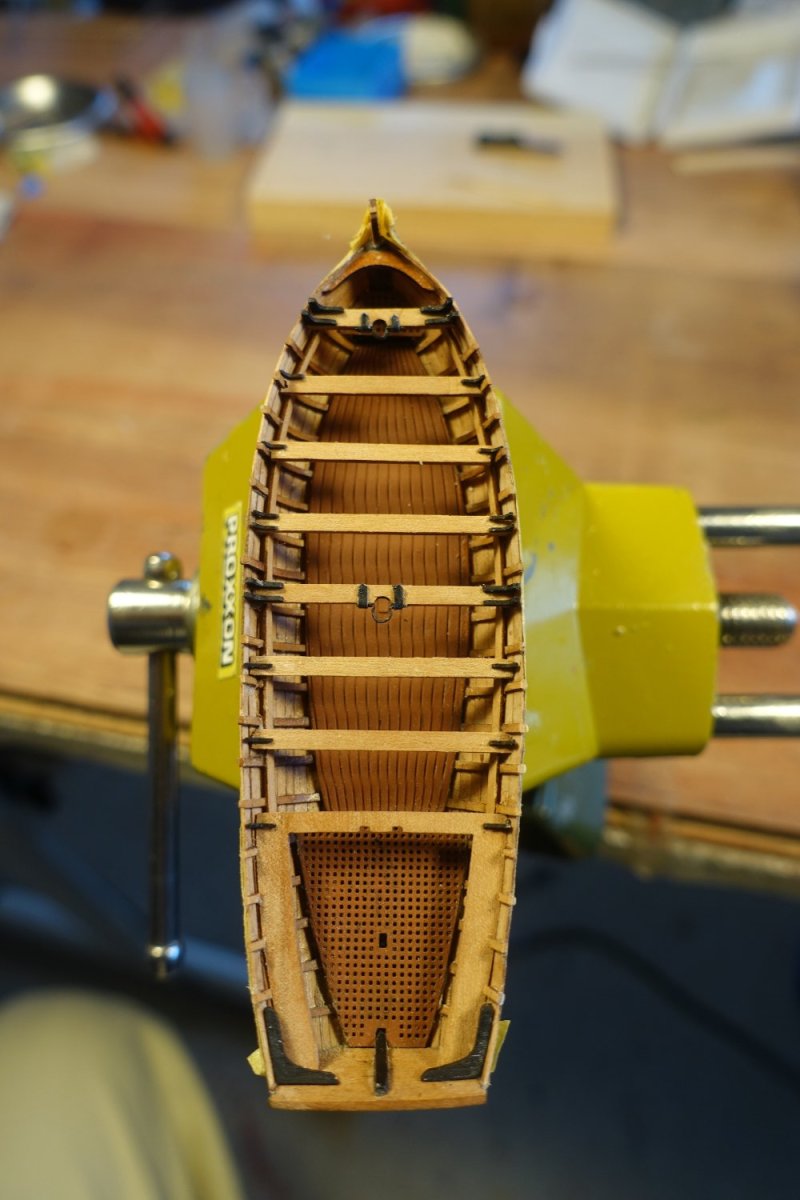
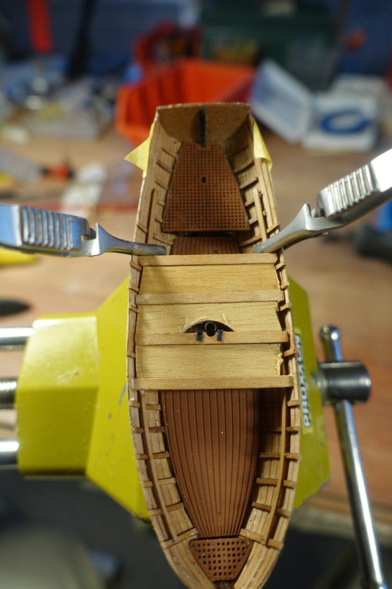
Thwarts The thwarts were attached to the supports. A 1x7mm strip was used as a spacer between the thwarts. Where ribs met the middle of the thwarts, I removed the rib section above the supports. Later, knees have to be attached in the middle of the thwarts, which may come into conflict with the ribs. It is not shown on the plan, but Chris has prepared two mast brackets on the brass sheet. Unfortunately, one of them was swallowed by the carpet monster. Therefore I made a replacement from a brass bar of the brass sheet Short pieces of ribs were glued to the rear seats. The kit includes 20 knees for the thwarts. According to Chris' plan, however, 7x4 + 2, i.e. 30 knees, are required. Even if you only use two knees per thwart, that's still 16 knees, so there's not much in reserve. I painted the knees black at first. The knees are attached. For the thwarts with the mast brackets, I used two knees on each side taken from the wood sheet of the pinasse (also part of the Sphinx kit). There are really quite few knees provided for the launch on the wood sheet. One Launch knee snapped off and I couldn't find it again.


- 22 replies
-
- 2
-
-
- 24 ft Launch
- Vanguard Models
- (and 1 more)
-
The thwarts were attached to the supports. A 1x7mm strip was used as a spacer between the thwarts. Where ribs met the middle of the thwarts, I removed the rib section above the supports. Later, knees have to be attached in the middle of the thwarts, which may come into conflict with the ribs. It is not shown in the instructions and also not on the plan, but Chris has prepared two mast brackets on the brass sheet. Unfortunately, one of them was swallowed by the carpet monster. Therefore I made a replacement from a brass bar of the brass sheet. Short pieces of ribs were glued to the rear seats. The kit includes 20 knees for the thwarts. According to Chris' plan, however, 7x4 + 2, i.e. 30 knees, are required. Even if you only use two knees per thwart, that's still 16 knees, so there's not much in reserve. I painted the knees black at first. The knees are attached. For the thwarts with the mast brackets, I used two knees on each side taken from the wood sheet of the pinasse (also part of the Sphinx kit). There are really quite few knees provided for the launch on the wood sheet. One Launch knee snapped off and I couldn't find it again.


- 22 replies
-
- 5
-
-
- 24 ft Launch
- Vanguard Models
- (and 1 more)
-
Thank you very much for the encouraging words. Once you get to grips with the peculiarities of these small boats, it really is a pleasure to build them. Clark
-
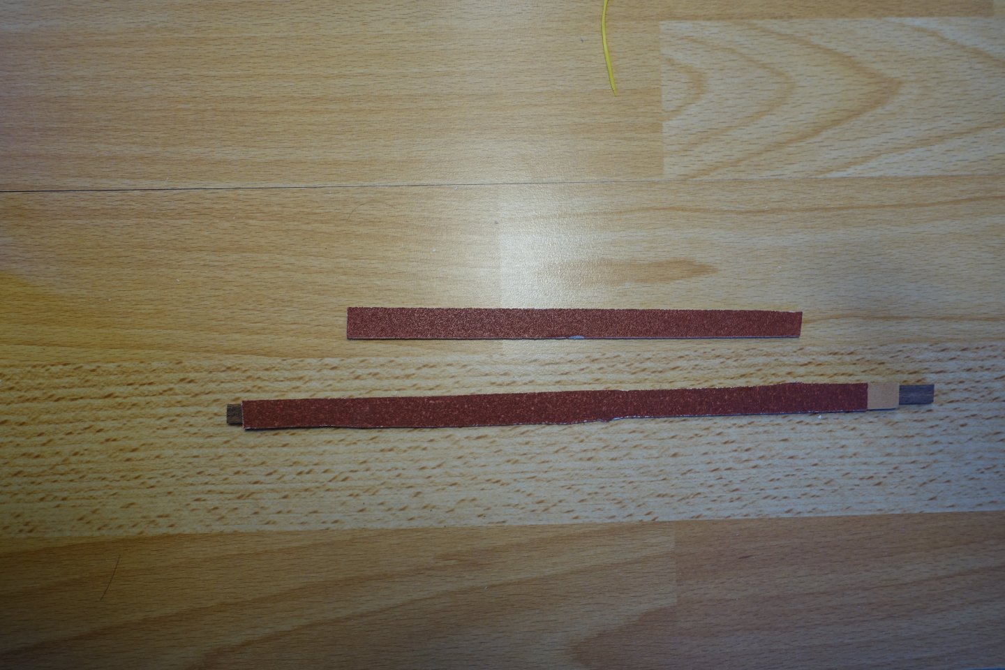
Thank you very much. I found the suggested method of pencil markings too imprecise, as the distance to the edge is difficult to mark. Clark
-
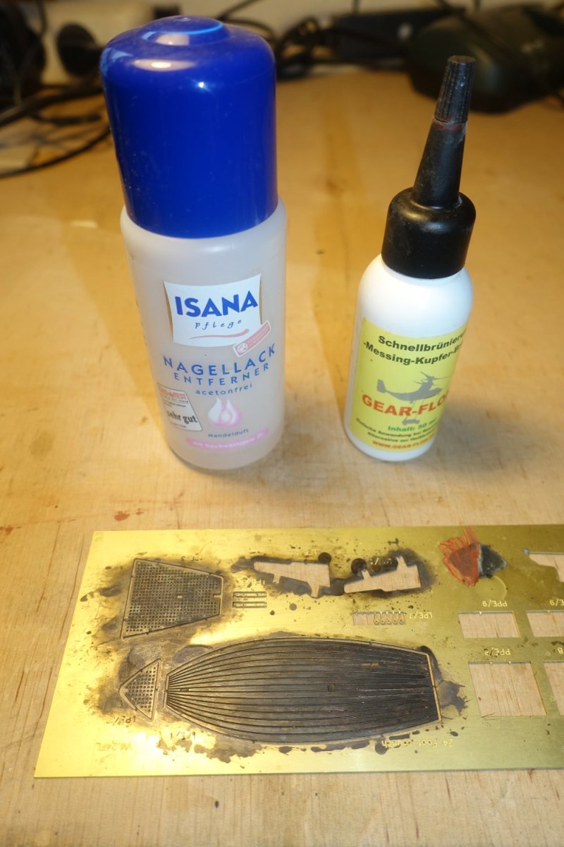
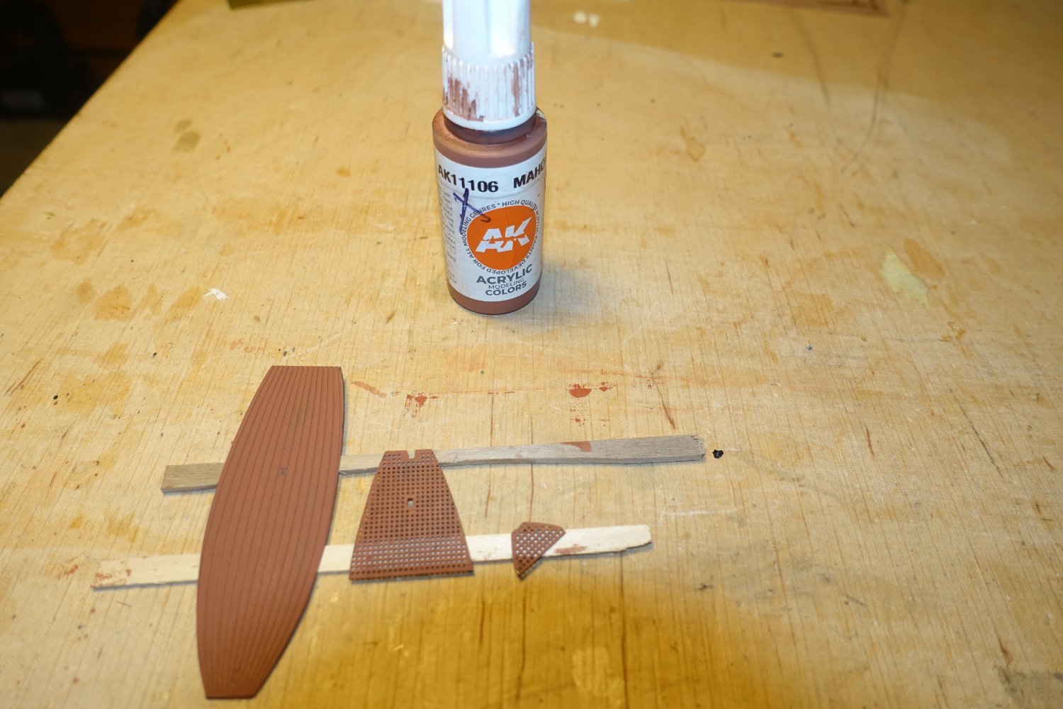
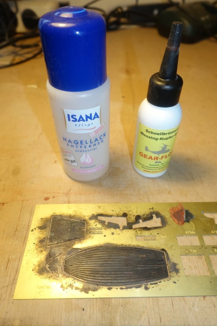
Just a short update: preparation of floor The brass floor was first cleaned with nail polish remover and then treated with a blackening solution acting quickly. This type of solution does not produce such good results for blackening, but it does provide a base for subsequent painting. The "floorboards" were then painted mahogany.

- 22 replies
-
- 4
-
-
- 24 ft Launch
- Vanguard Models
- (and 1 more)
-
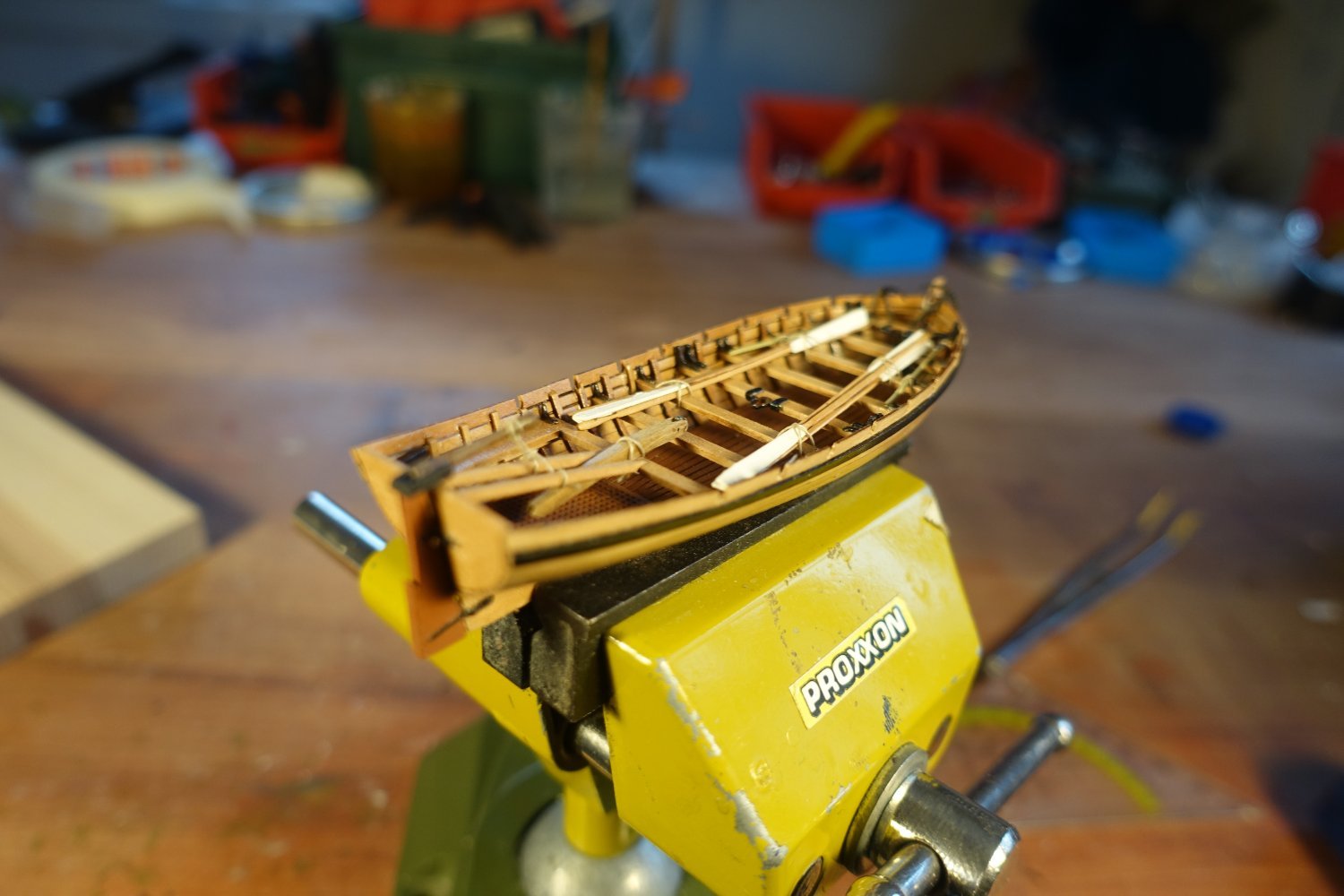
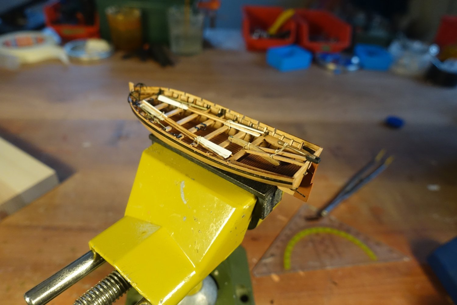
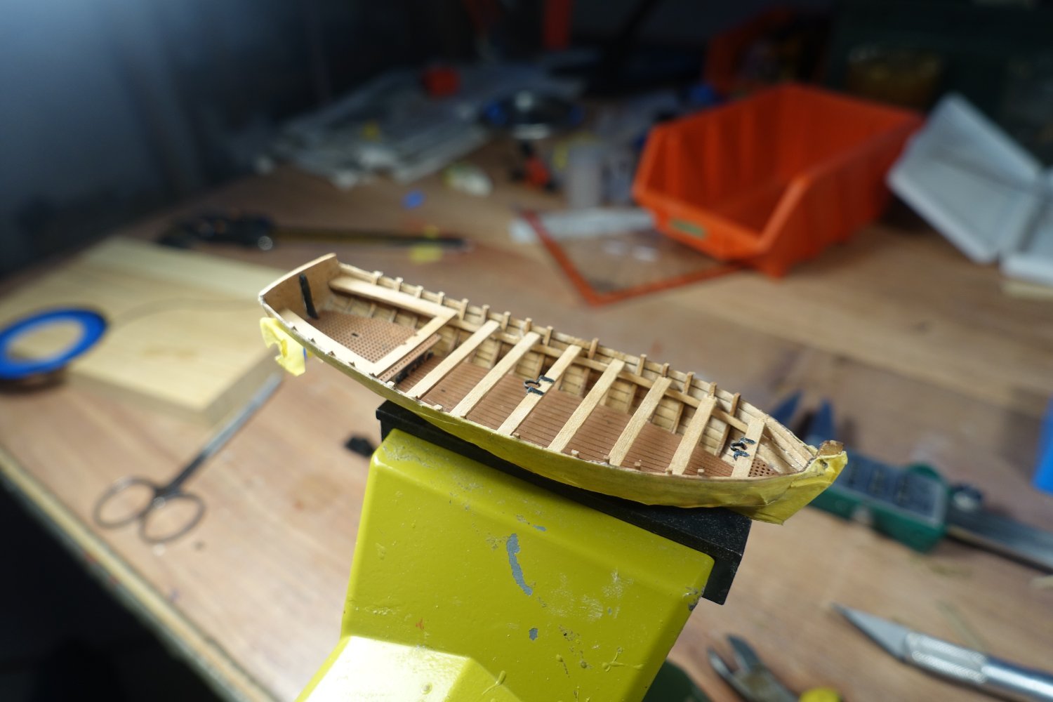
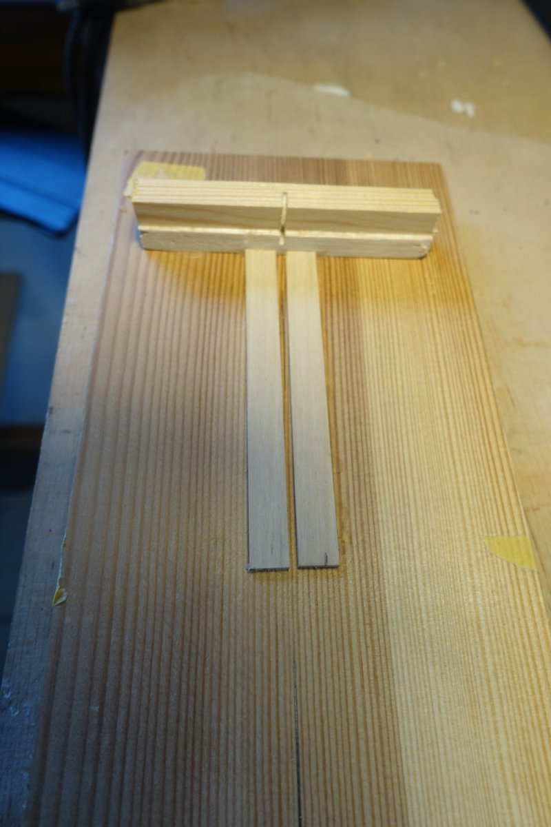
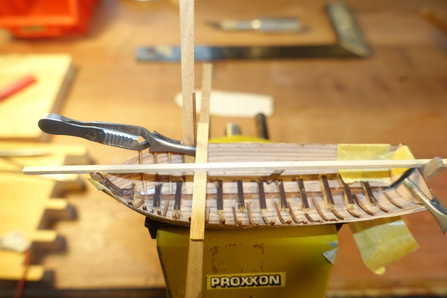
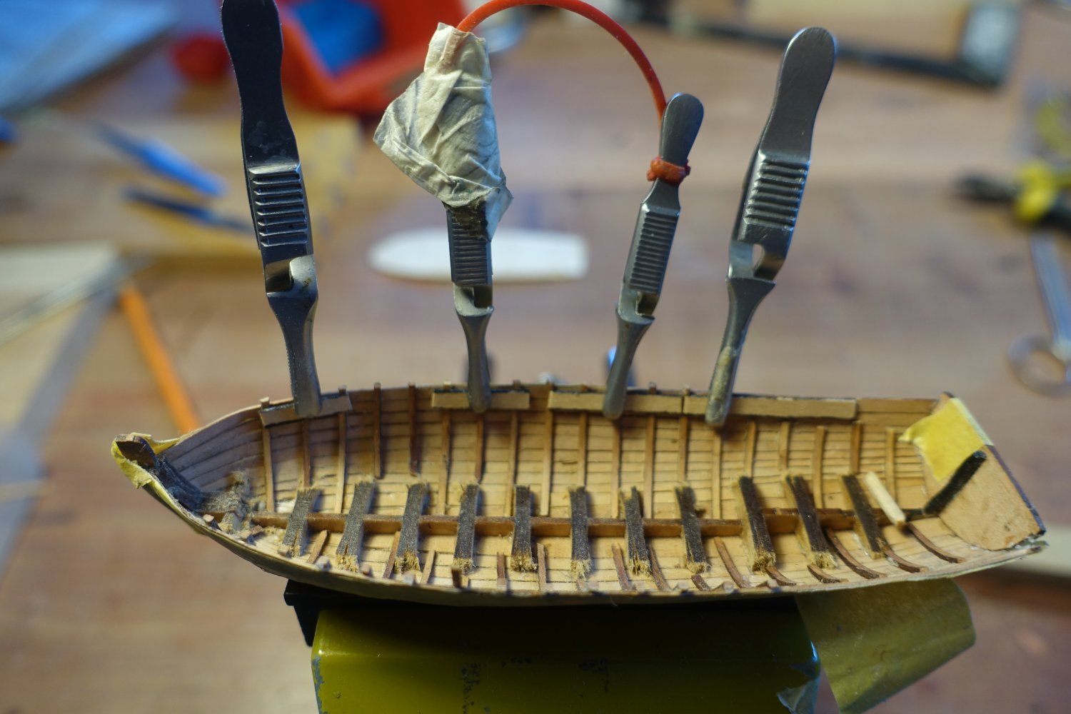
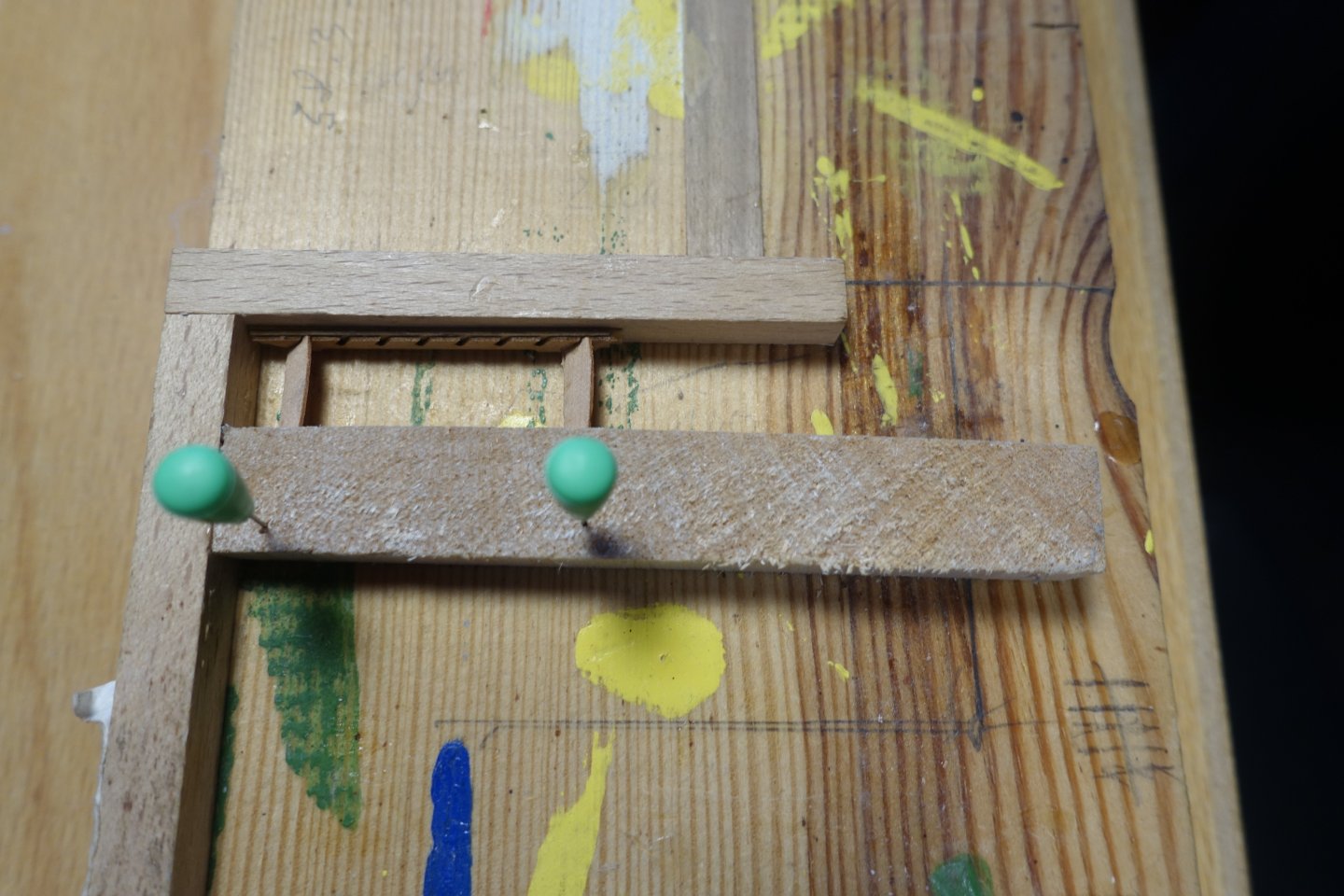
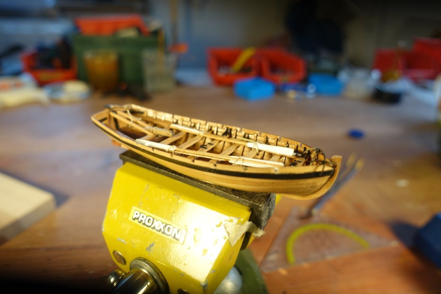
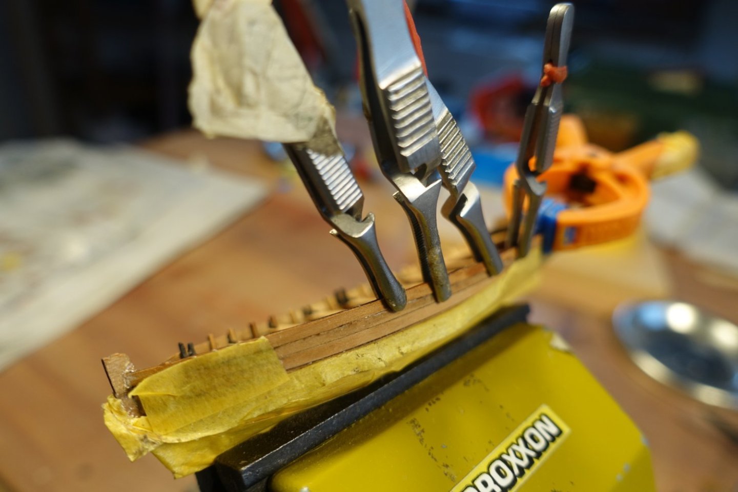
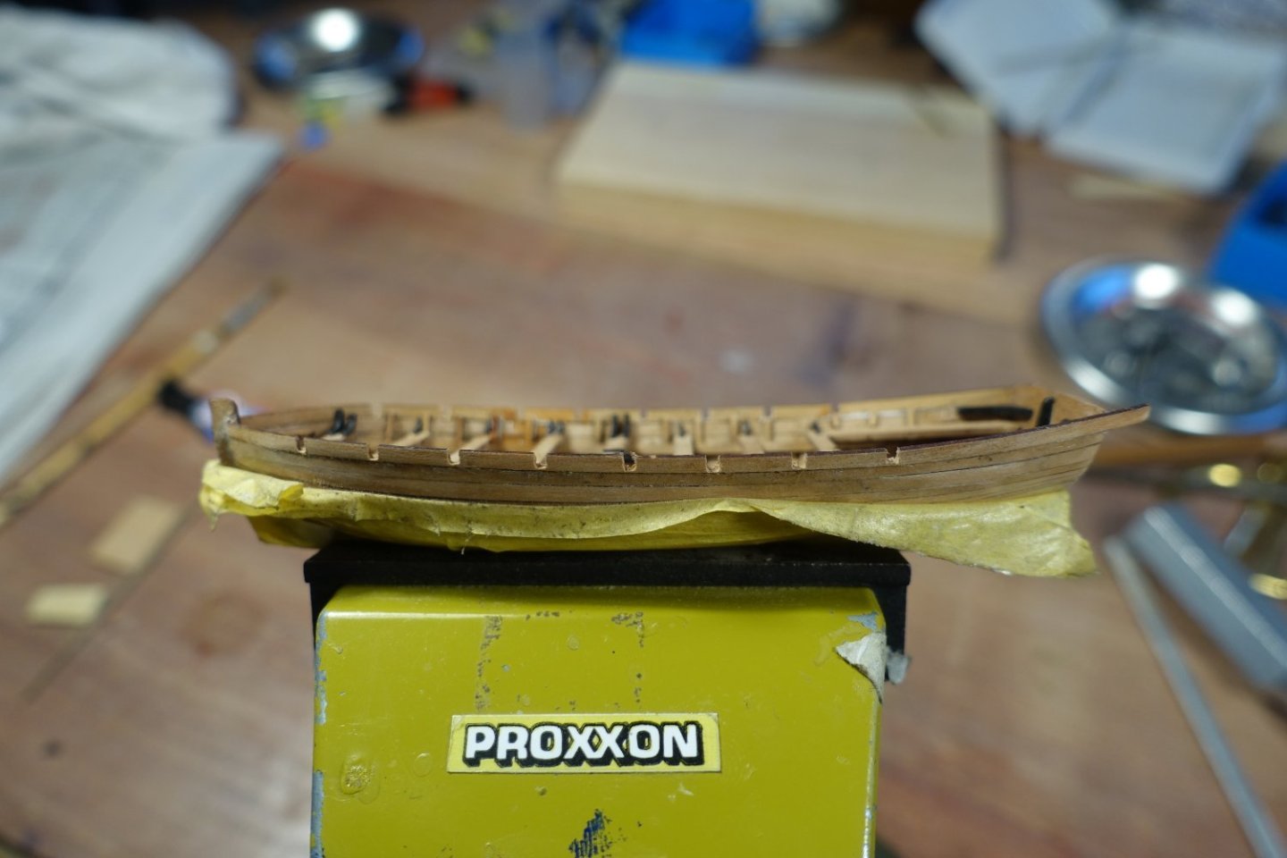
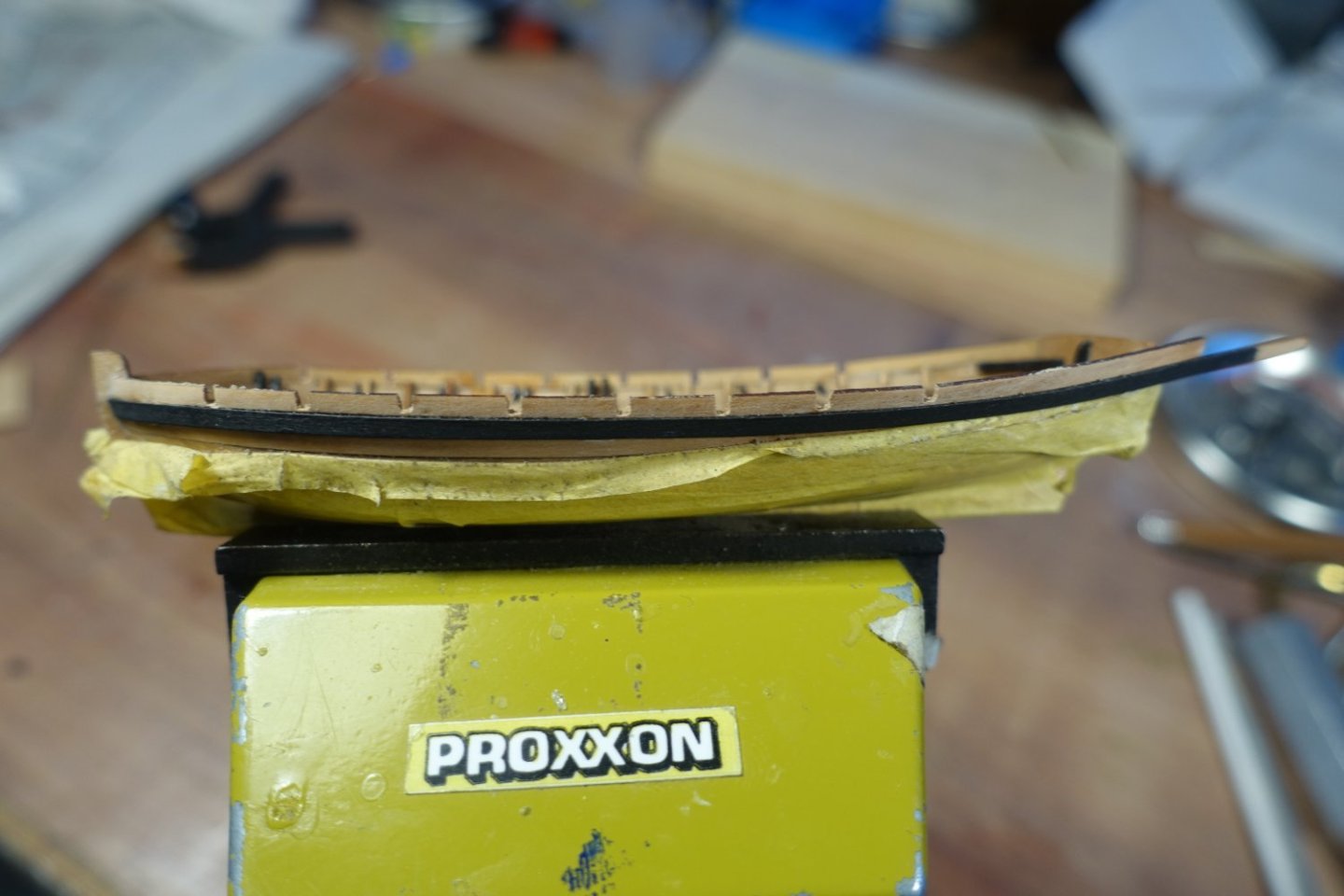
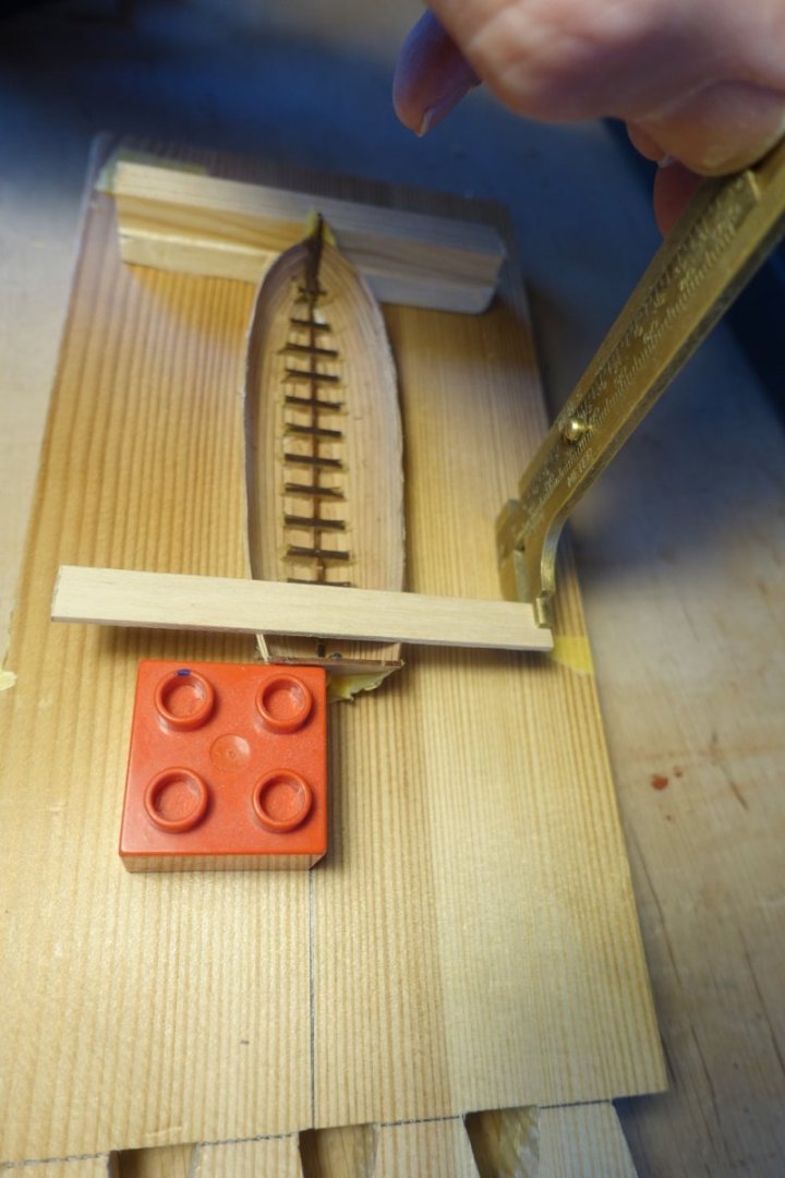
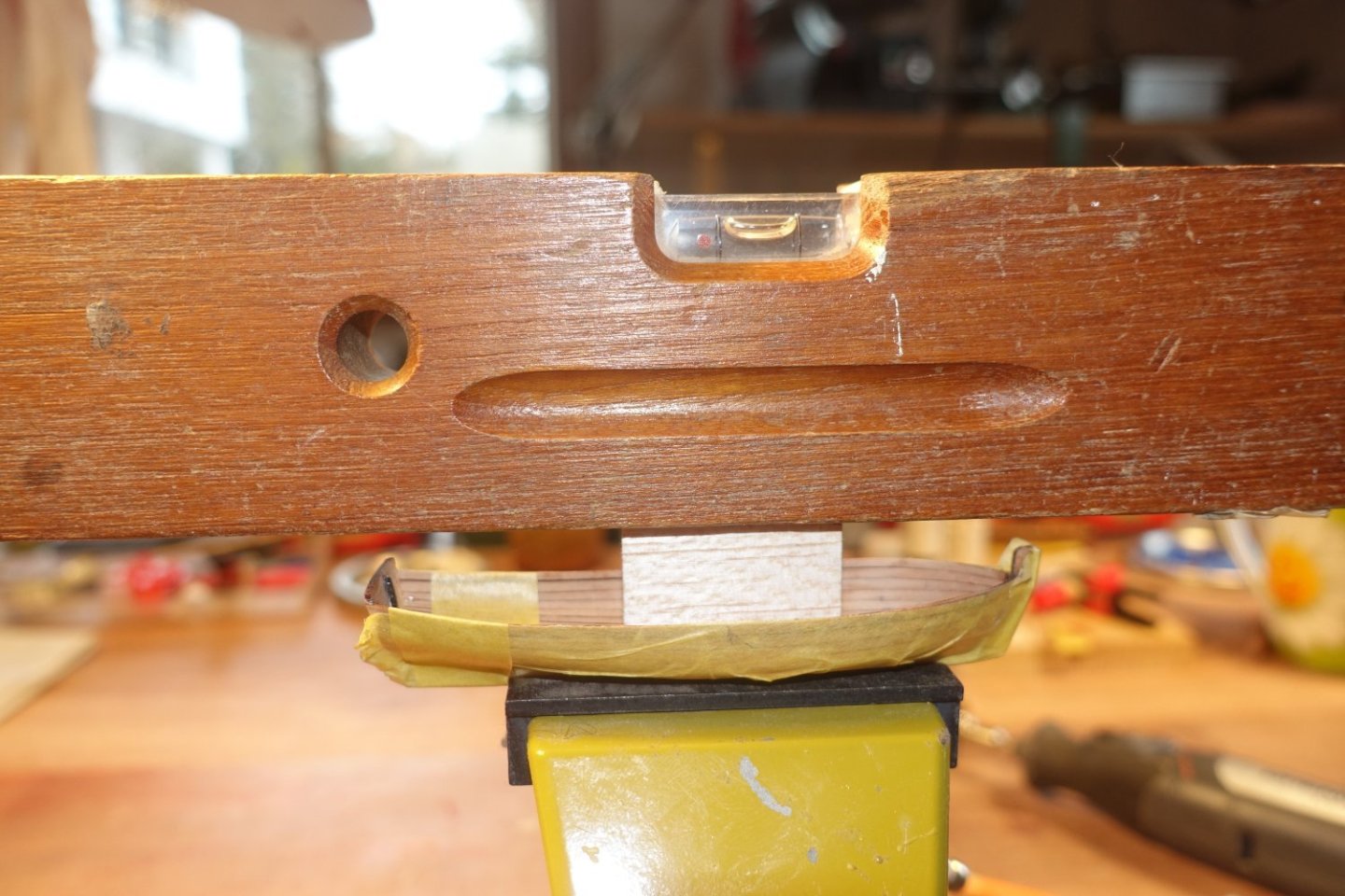
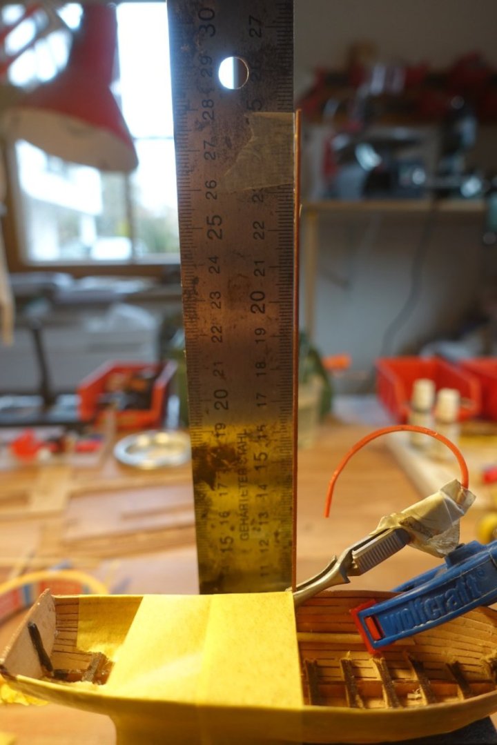
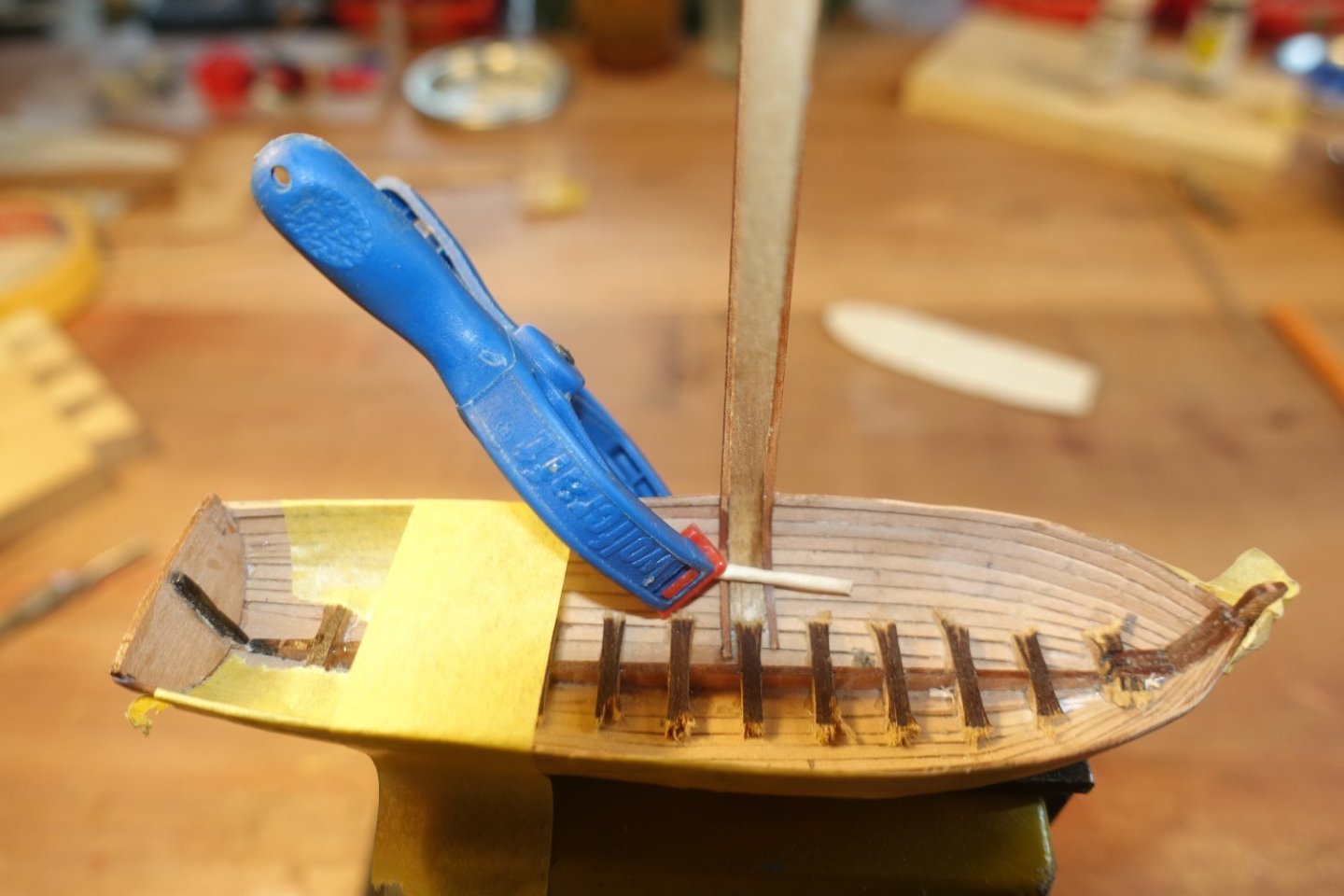
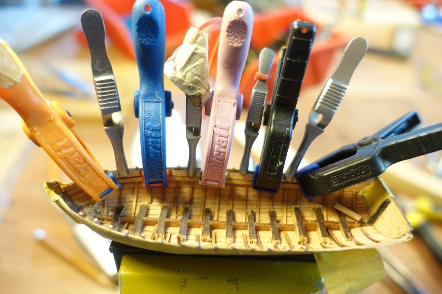
Ribs To level the starboard and port sides, I made a simple mini shipyard. The launch is clamped in it, the vertical alignment is checked using a Duplo brick, which is brought into line with the sternpost. The distance to the bottom board is measured on both sides of the boat using a strip laid over the edges of the hull and the edge of the hull is sanded very lightly (!) if necessary. A minimal correction was only necessary in the stern area on the port side. The boat was leveled along its longitudinal axis. The ribs were bent at their ends using heat (top). I did the same with a 0.5x5 mm strip, which will later serve as a spacer between the ribs (bottom). The first rib was attached with PVA, the vertical alignment was checked with the help of a right angle. The previously bent 0.5x5mm strip was placed against the first rib and the second rib was then placed against the 0.5x5mm strip and glued to the hull. To align the ribs on the starboard side to the same position as those on the port side, I built myself a small alignment aid. A 2x5mm strip was glued at right angles to a smaller strip. This smaller strip can then be aligned with the stem and sternpost, while the 2x5mm strip is inserted between the protrusions of the ribs on the port side. I let the ribs on the port side protrude about 2-3 mm over the edge of the hull. After all the ribs were attached, they were shortened. However, a 1mm overhang was left. The gunwale has to be fitted later. The overhang should serve to hold the gunwale in place. I used 3mm strips as spacers to attach the seat support strips at a distance of 3mm from the top of the bulwark. Using these strips as a guide, the seat support was glued on. After both supports had been fixed in this way, I checked again with strips laid across to see if the supports were correctly aligned.


- 22 replies
-
- 5
-
-
- 24 ft Launch
- Vanguard Models
- (and 1 more)