Clark
-
Posts
310 -
Joined
-
Last visited
Content Type
Profiles
Forums
Gallery
Events
Everything posted by Clark
-
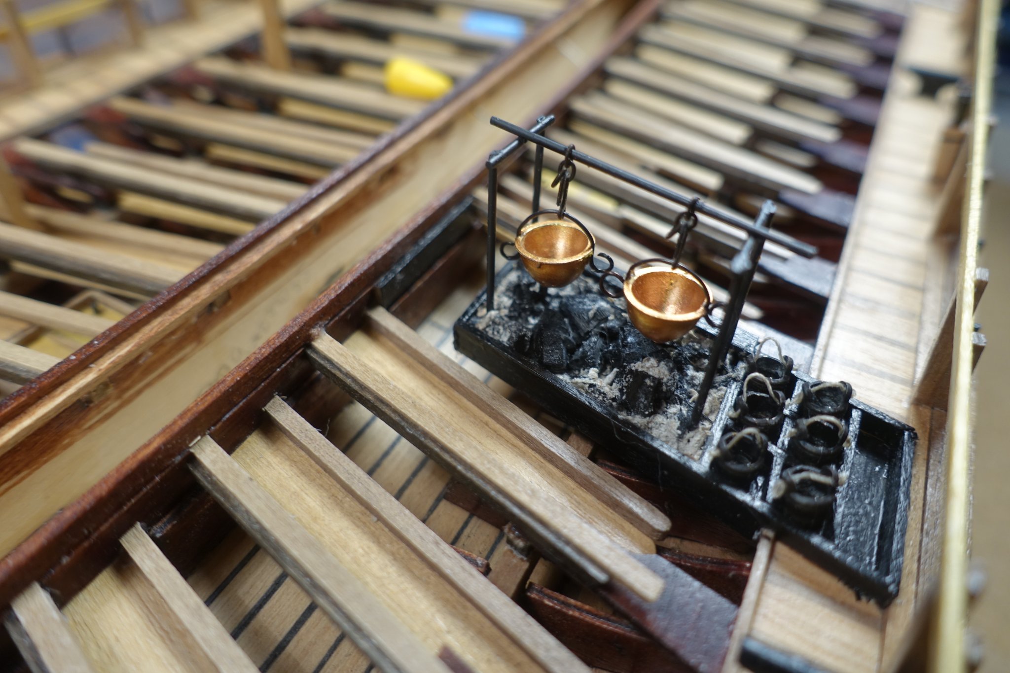
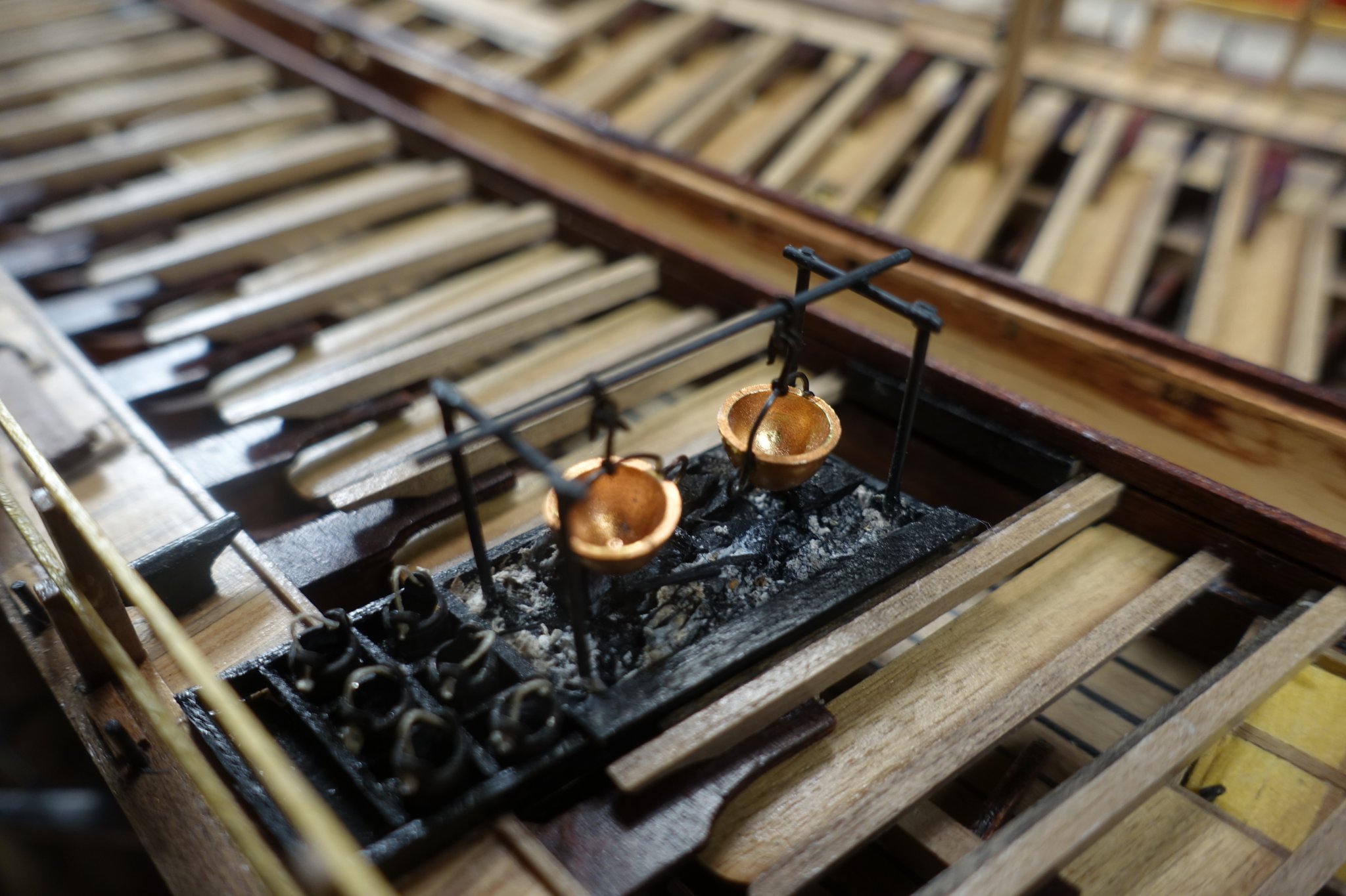
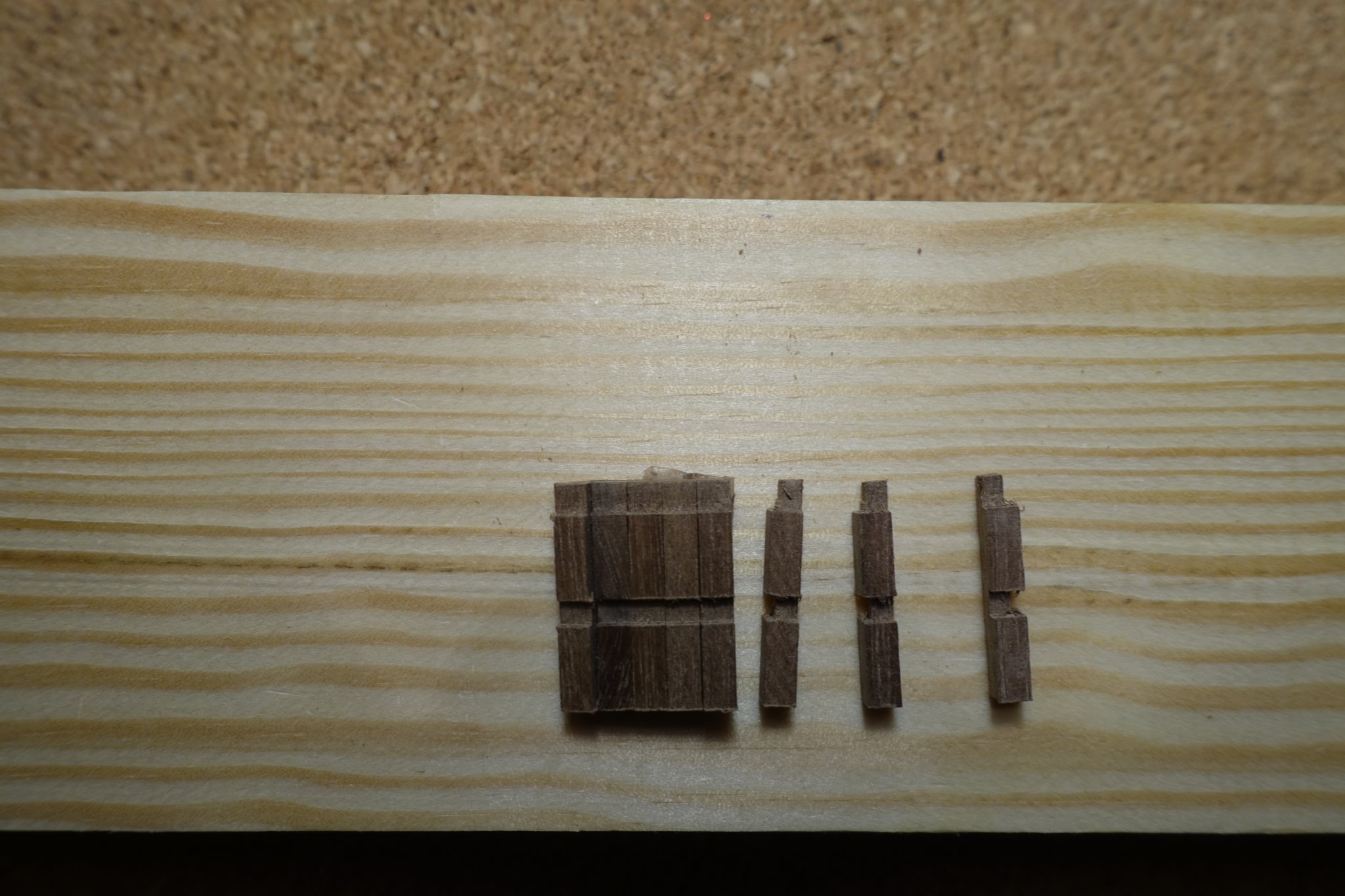
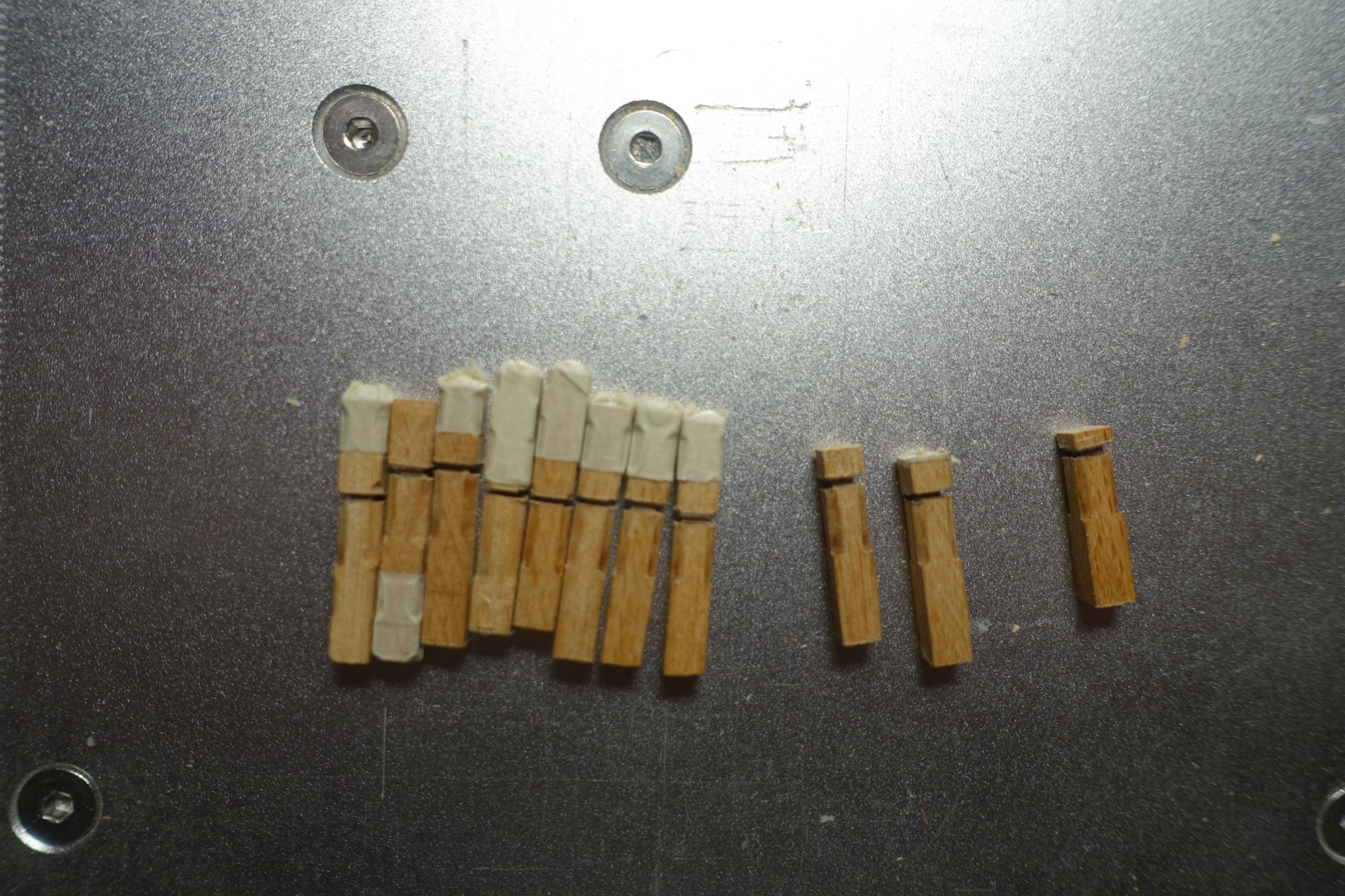
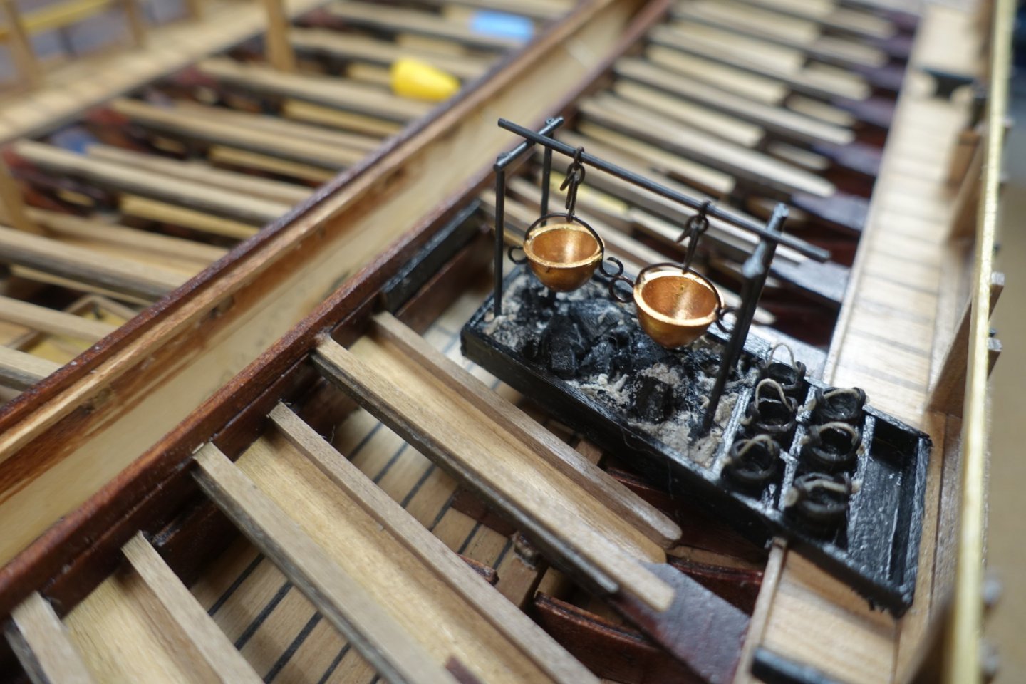
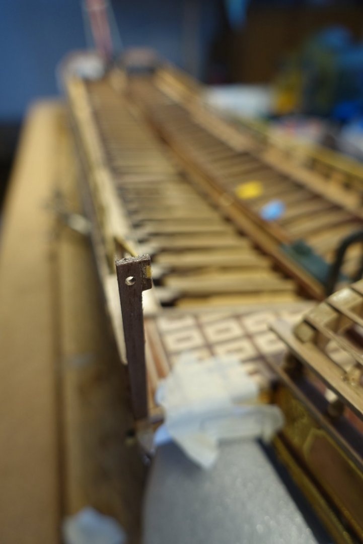
Cooking box is now ready. I added some ash and wood remnants from our fireplace. Since I was also wondering how the soup may be distributed, I put a bucket rack aside. Furthermore, I could not imagine how soup and fire could be handled. Therfore, I glued a walking plank on one side of the cooking box. A further question still bothers me: Are two pots with a diameter of ~60 cm really enough for ~500 hungry man working hard. While the glued ash of the cooking box was drying, I started to think about the swivel guns and I have noticed that the supports I have already mounted were much to high for an adequate handling. Thus I started to dismount them and to shorten them. Fortunately, wood is very patient. Picture shows a support already shortened.

- 112 replies
-
- 5
-

-
- corel
- reale de france
- (and 1 more)
-
Thats what was also reported to me but I hope that this will not affect the interrelationsuip between the modellers like Pablo, Paul or Pov. Clark
-
Sorry for bothering you: Keel length including stern post?
-
Hi Chris, Thanks for the rapid anser. I took a wrong conversion factor foot into m. Again Thanks, Clark
-
Hi Chris, I noticed you are very busy. Thus, only a short question. Maybe a silly question, but is my calculation correct?: 28 feet = 9, 2 m /scale 1:64= 14 cm? I am asking because I would like to order one and hesitating about the correct size for my ship 1:64 scale. Moreover, there are a lot of reports in the German radio and TV declare that British products are very difficult or even impossible to deliver to the continent not because of Corona but because of Brexit. I hope you are not affected. Clark
-
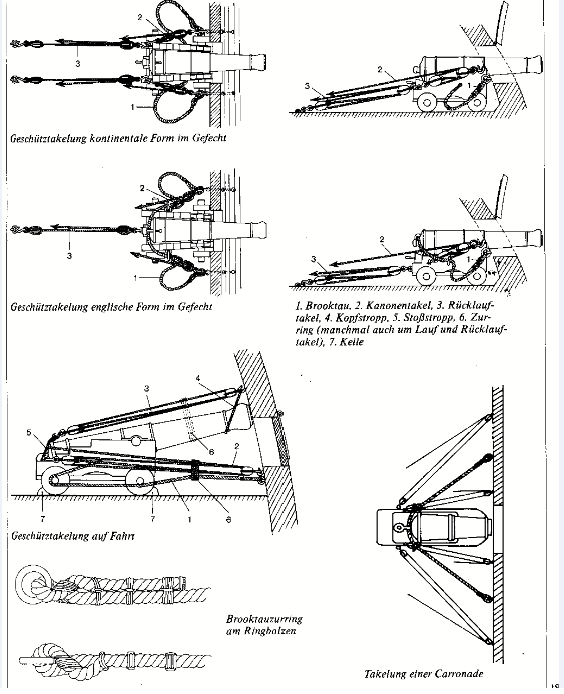
Hi Glenn, Do you want to rig the cannons as beeing in figth or as beeing on trip? Picture below explains what I mean. Regarding the Duchess, cannons in fight might probably look better (onyl my opinion). Clark
- 382 replies
-
- 2
-

-
-
- Vanguard Models
- Duchess of Kingston
- (and 1 more)
-
Thanks Frank, you are right. I spent a lot of time working on the ship during the last weeks. It relaxes me really. I am happy that my 5 year old granddaughter stayed in your house for some days and even "helped" me in sanding, cutting and gluing. Im not so good in playing with dolls. Hope to find some news from your ship soon. Clark
- 112 replies
-
- 1
-
-
- corel
- reale de france
- (and 1 more)
-
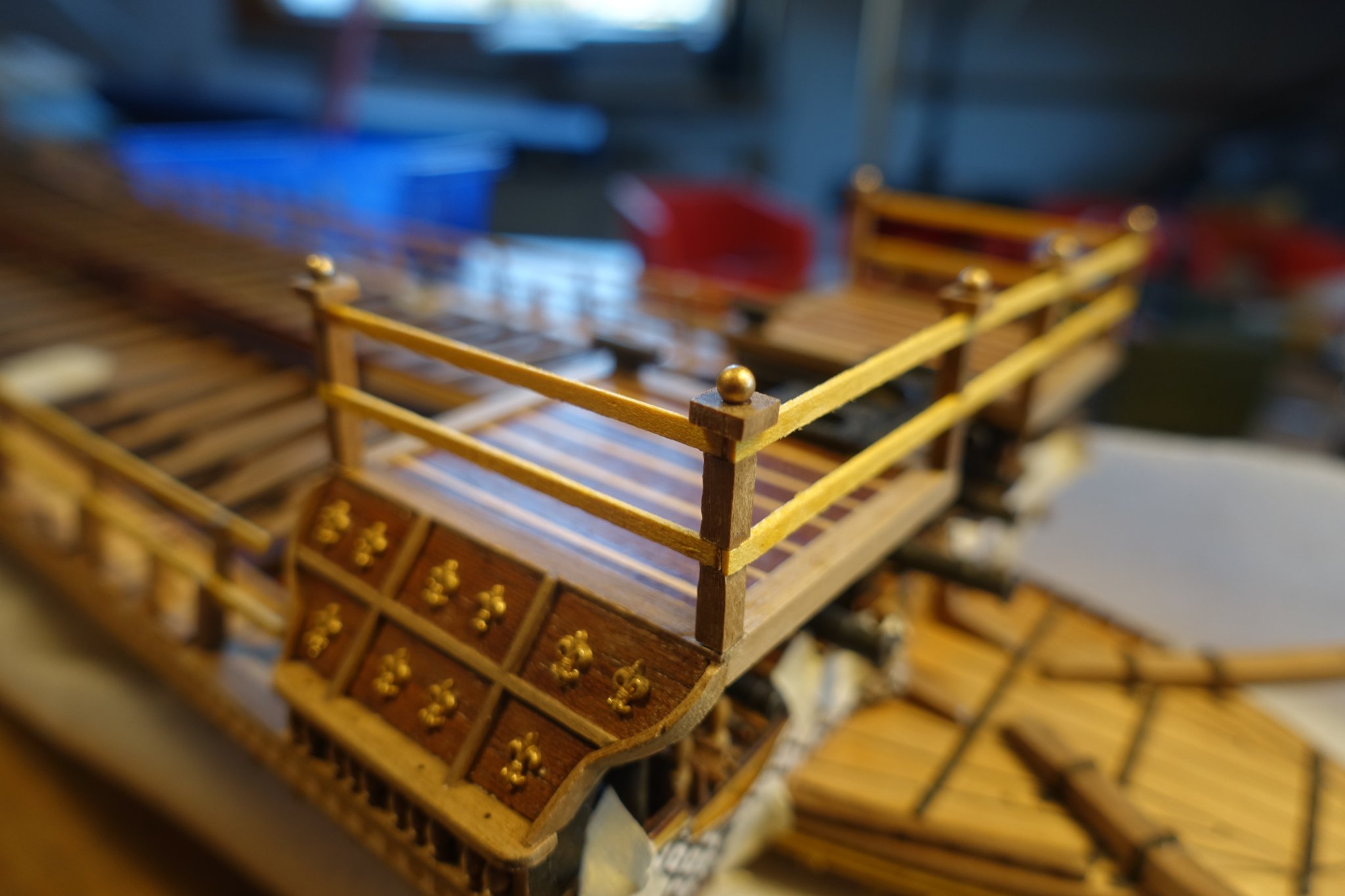
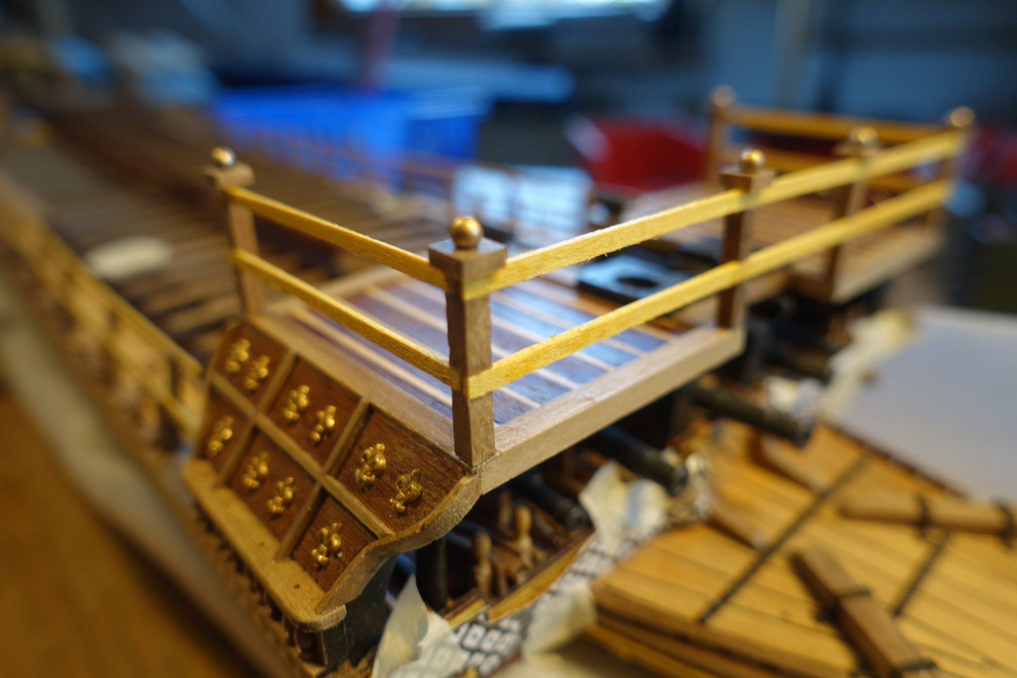
Forecastle handrails were prepared and added. I put balls usually used for ball bearings on the top. Might be kitschy, but I thought there should be an end at the top. Clark


- 112 replies
-
- 6
-
-
- corel
- reale de france
- (and 1 more)
-
Excellent idea to construct a spacer. I used a triangle placed on the midline which led to a lot of repeated measurements. Clark
- 510 replies
-
- 1
-
-
- reale de france
- corel
- (and 1 more)
-
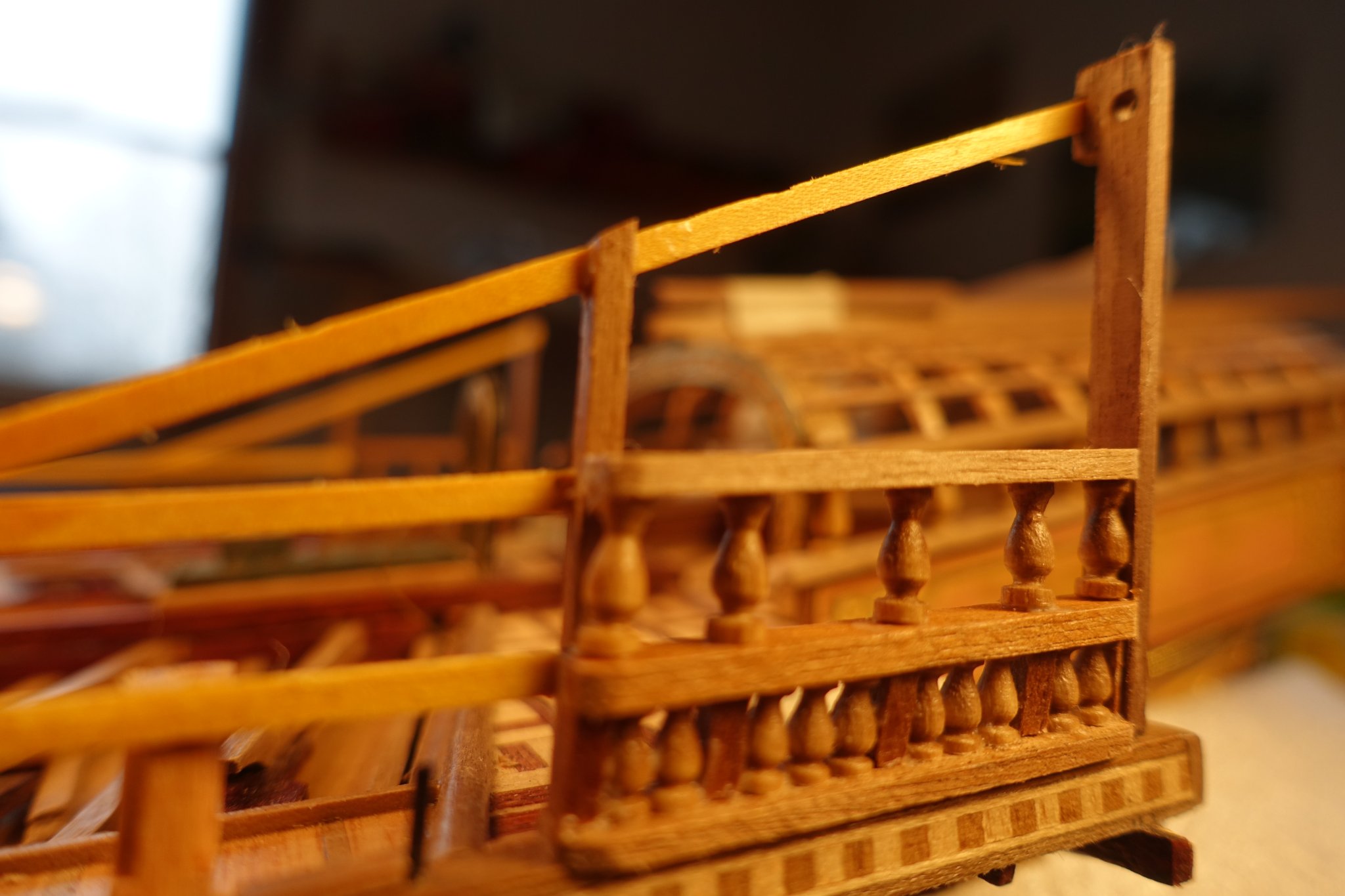
According to the Corel plans, there should be a decoration plate at the stern similar to the one at the bow showing lily ornaments. Since I run out of the ornaments, I replaced the decoration plate by pillar rows.

- 112 replies
-
- 4
-
-
- corel
- reale de france
- (and 1 more)
-
Hi Frank, glad you are back. It is a good idea to add rudder pendents. However I thought they were not in use such early. Below a photo from http://militaryhistory.x10.mx/shippictures/art_galleys_and_galleasses_03.htm showing the rudder area. How many of the ornaments are left? There a still some needed for decoration at the stern. Clark
- 510 replies
-
- 6
-

-
-
- reale de france
- corel
- (and 1 more)
-
Hi Frank, meanwhile I removed the rudder assembly from the ship. I am afraid that it will be damaged while handling and turning the ship. Clark
- 112 replies
-
- 1
-
-
- corel
- reale de france
- (and 1 more)
-
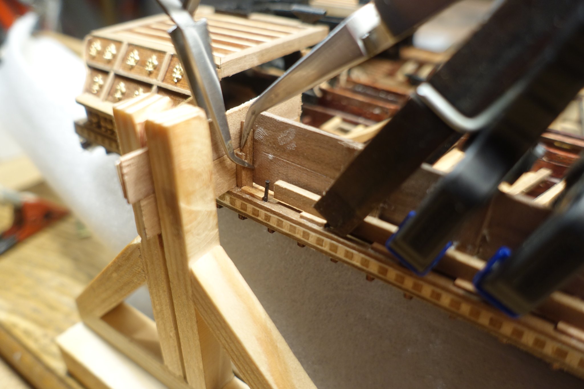
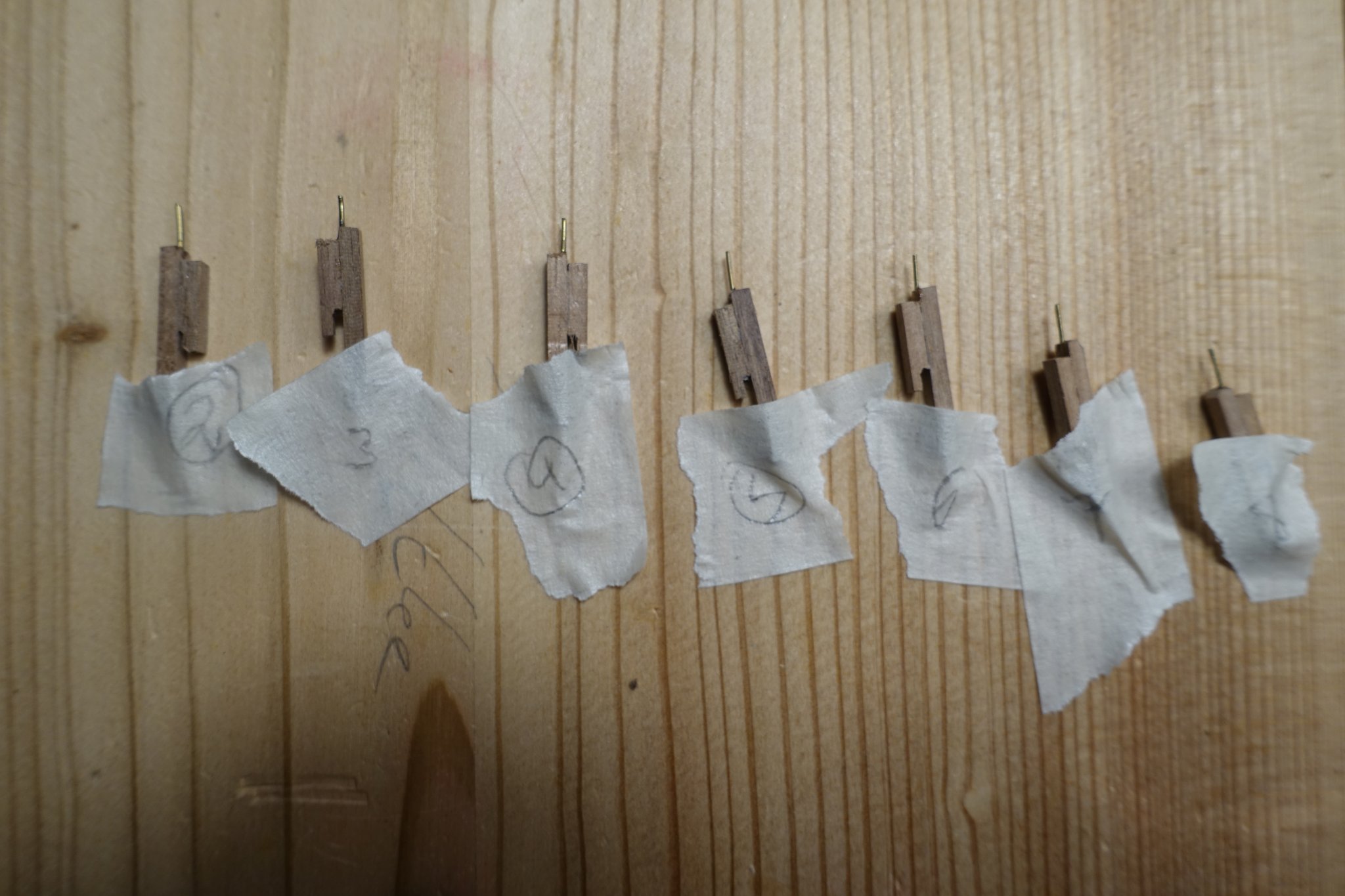
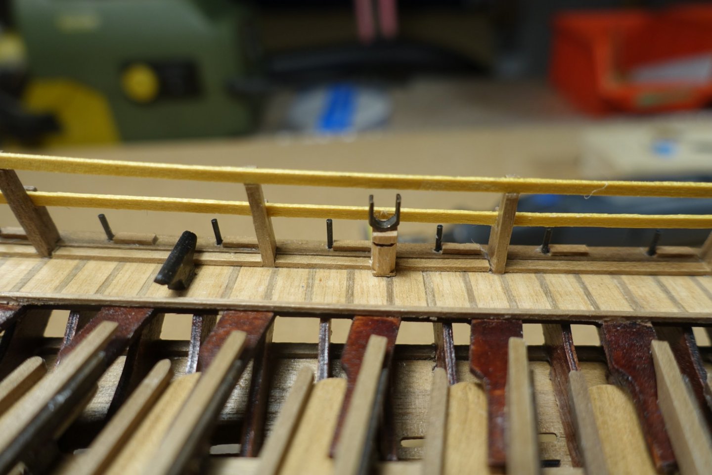
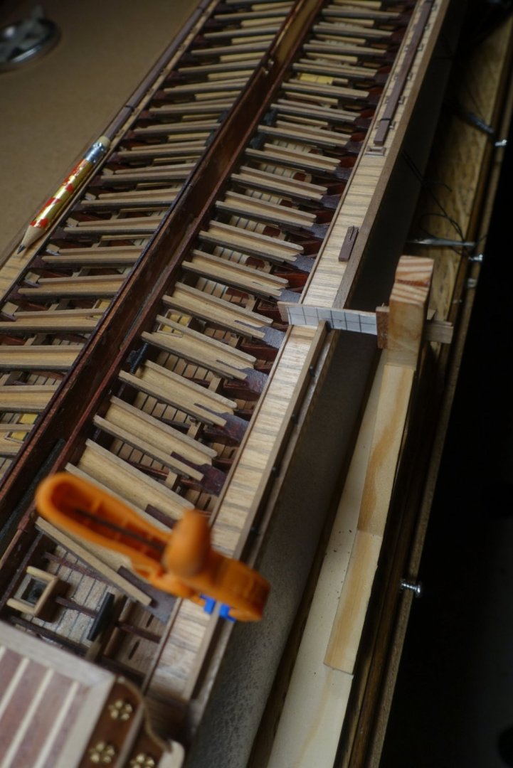
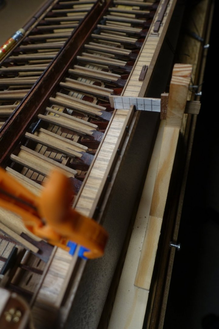
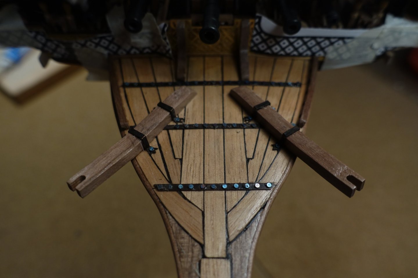
Hi Frank, height of the pins was adjusted to 5mm. Oars including protective boards at the that point are 5mm x 3 mm (width x height). Oar supports were cut to 7 mm. This there is 2 mm space left in both direktions. Hope it works when oars will be fixed. I placed the pins perpendicular to the waterline. To adjust the ship at the waterline, I took the distances from the corel plan showing that the stern yoke is 14 mm higher that the bow yoke. 14 mm is the number I reminder. I am not quite sure. To adjust the pins perpendicularly I used the holder shown above (#77). Since we will probably not be allowed to visit our children, living a bit far away, during Xmas due to Lockdown, I will probably spend more time with Reale. Clark
- 112 replies
-
- 1
-
-
- corel
- reale de france
- (and 1 more)
-
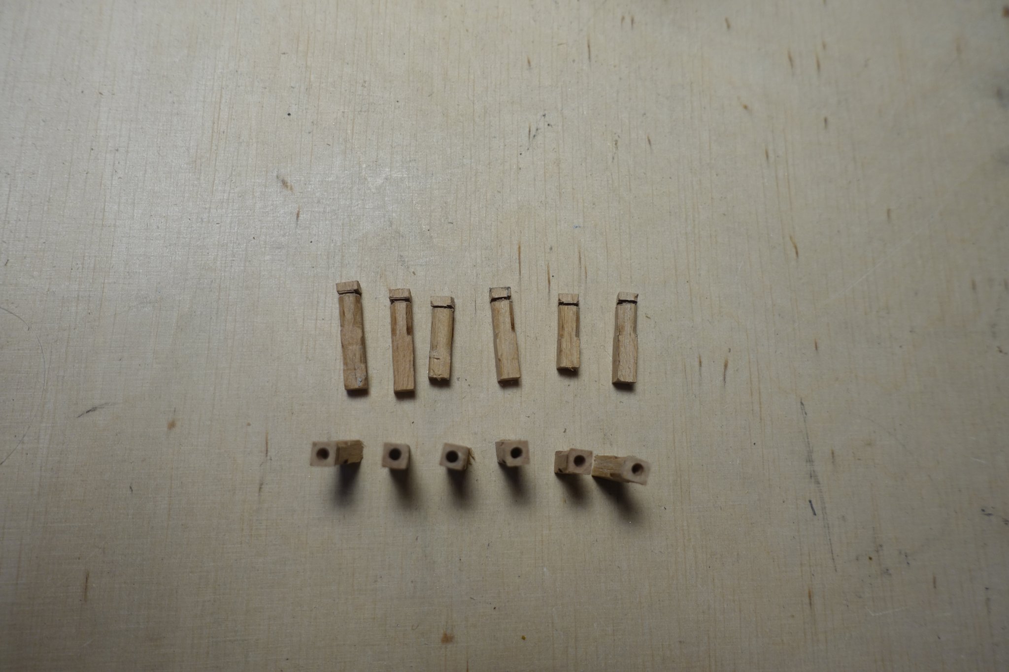
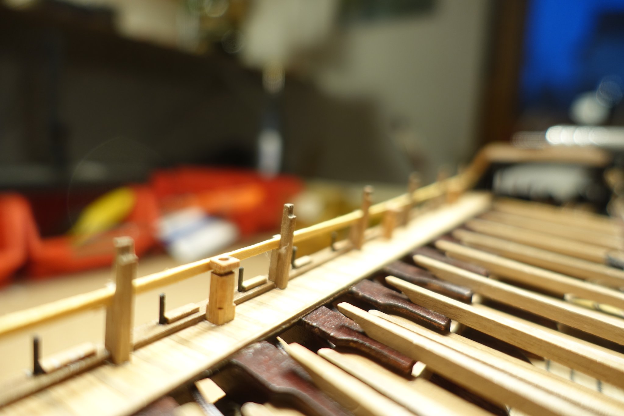
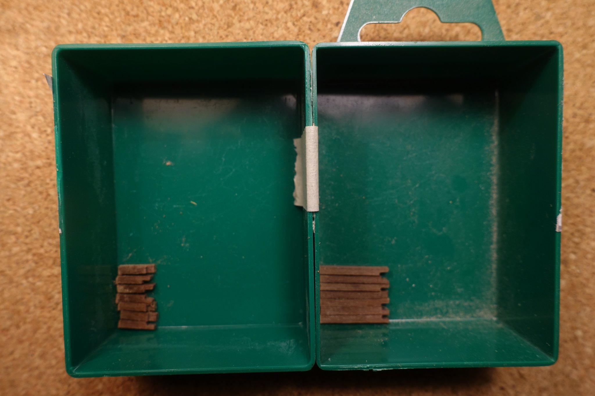
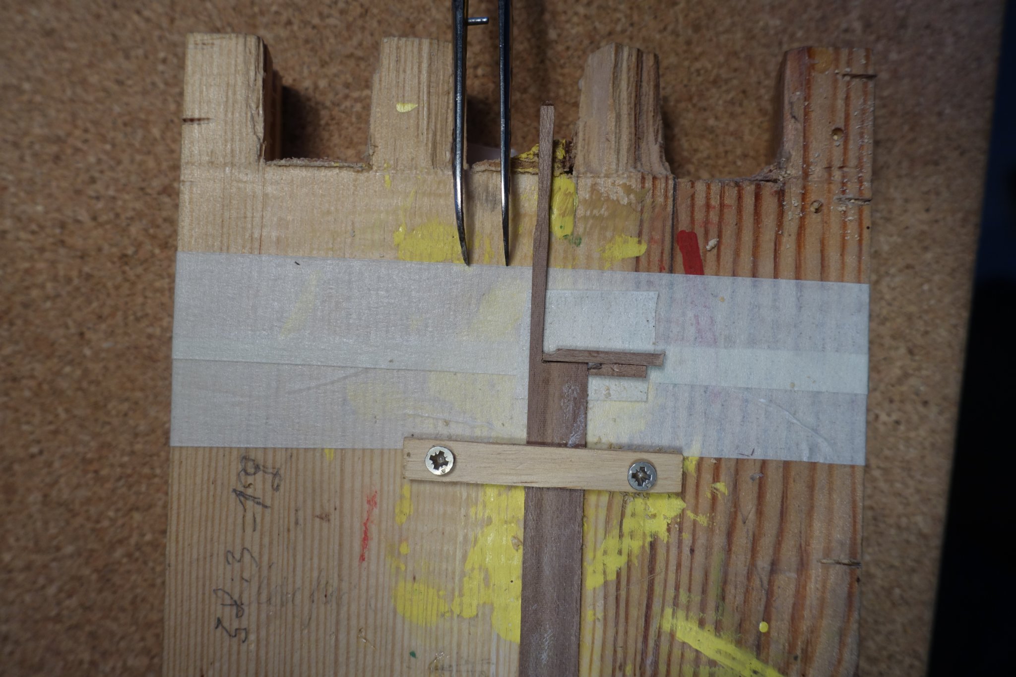
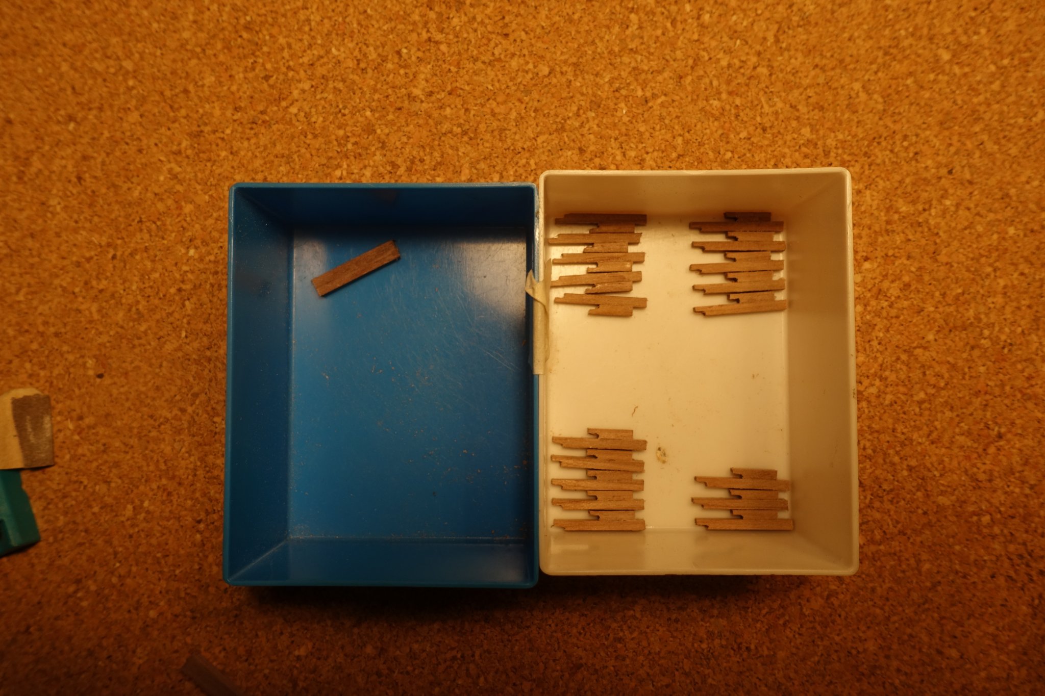
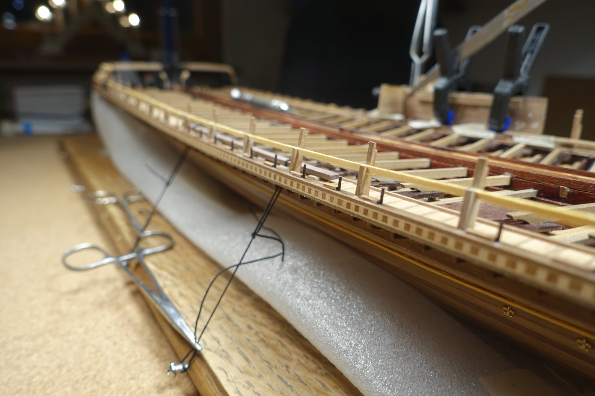
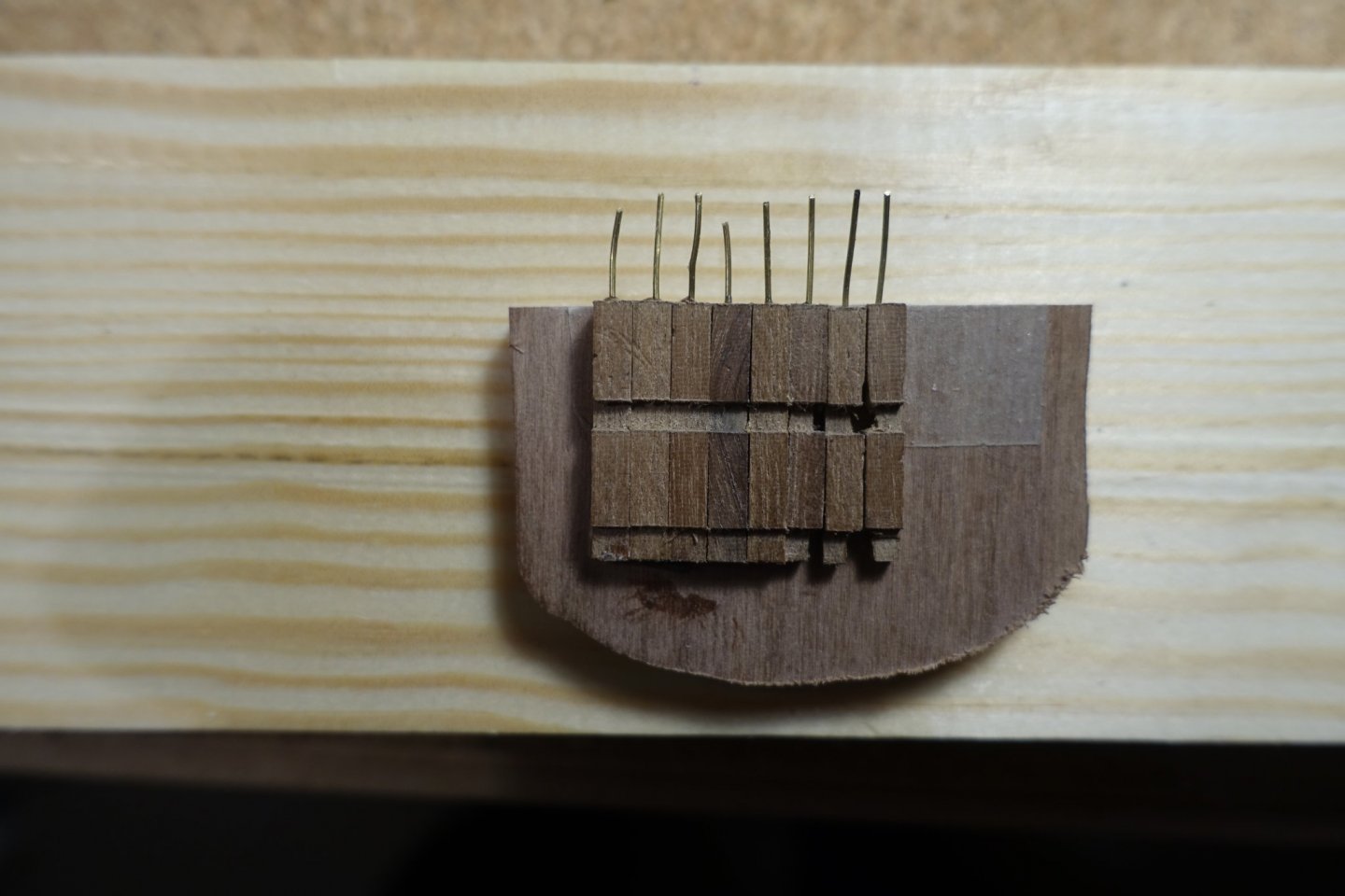
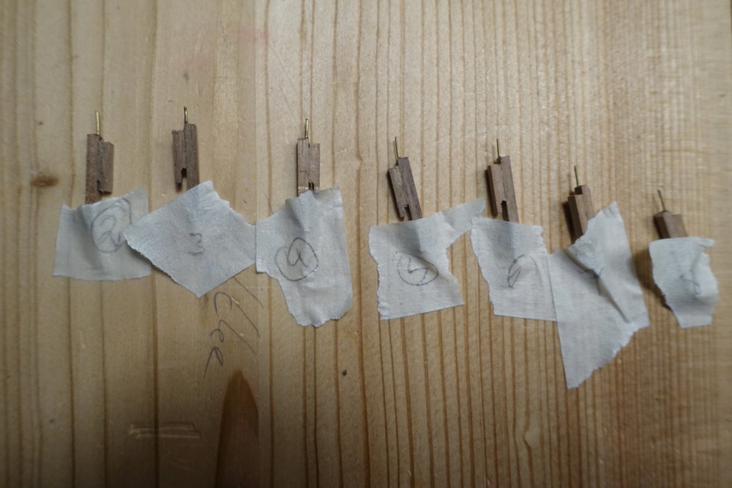
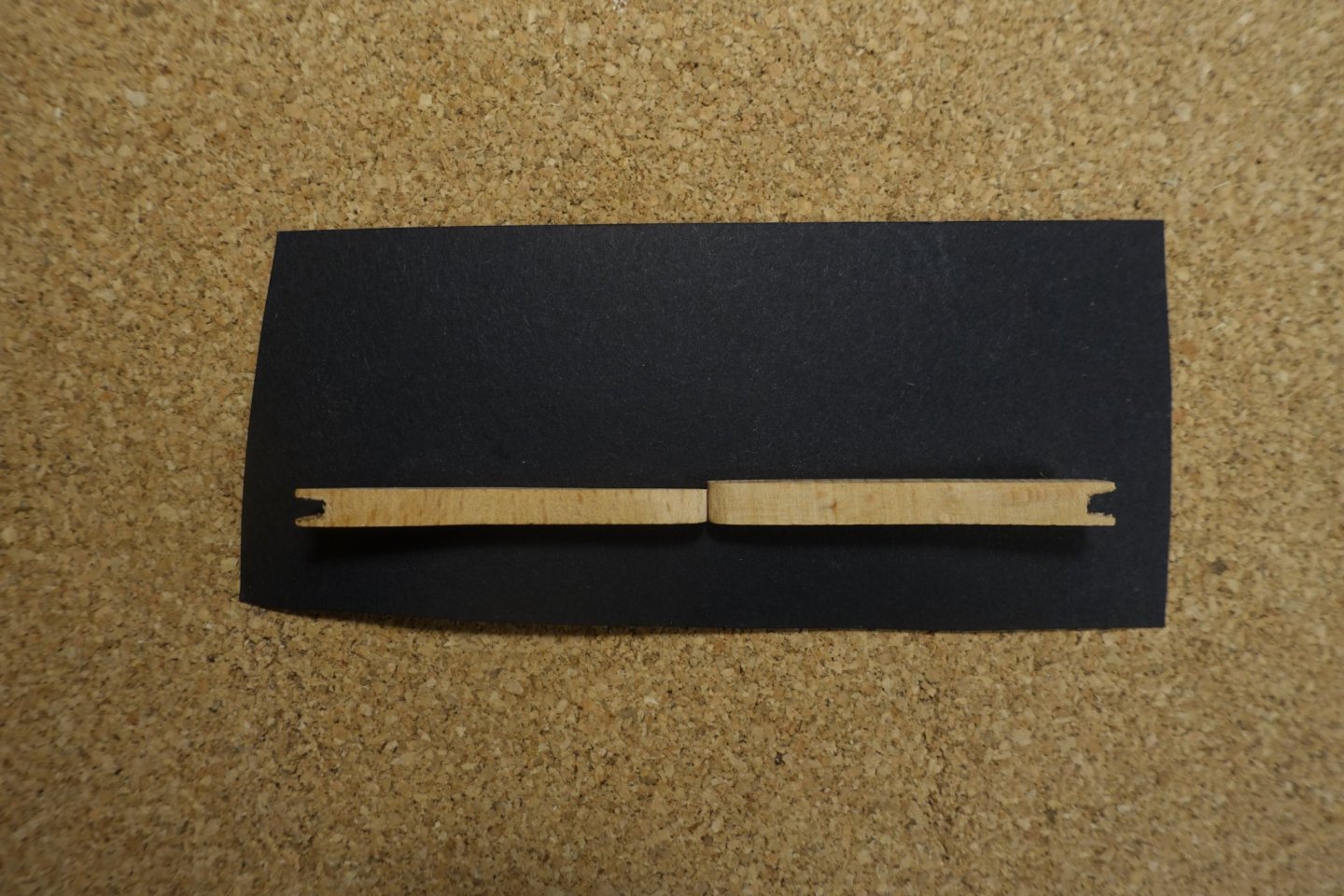
Next step was to arrange the thole pin of the oars. I hesitated if the pins had to be arranged on the bow or on the stern side of the oars, i.e. if the boat was pulled or pushed via the pins. They had to be arranged on the stern side of the oars meaning that the boat was pulled via the pins and oarloops. Gimo, thanks for providing the picture. To arrange the pins vertically, used the holder I had prepared for fixing the supports. Railing stanchions were prepared out of two 2x2 mm wood strips according to Corel suggestions. To get the correct and uniform placement of the small piece on the longer one, I used a simple walnut strip with an opening cut. To fix the stanchions on the deck, small pins were inserted. For arranging the stanchions vertically and horizontally I used the holder again. Stanchions and pins of the port side are now placed and glued.


- 112 replies
-
- 5
-
-
- corel
- reale de france
- (and 1 more)
-
Gimo, thanks for the comments, but I am not talented enough to do that. Clark
-
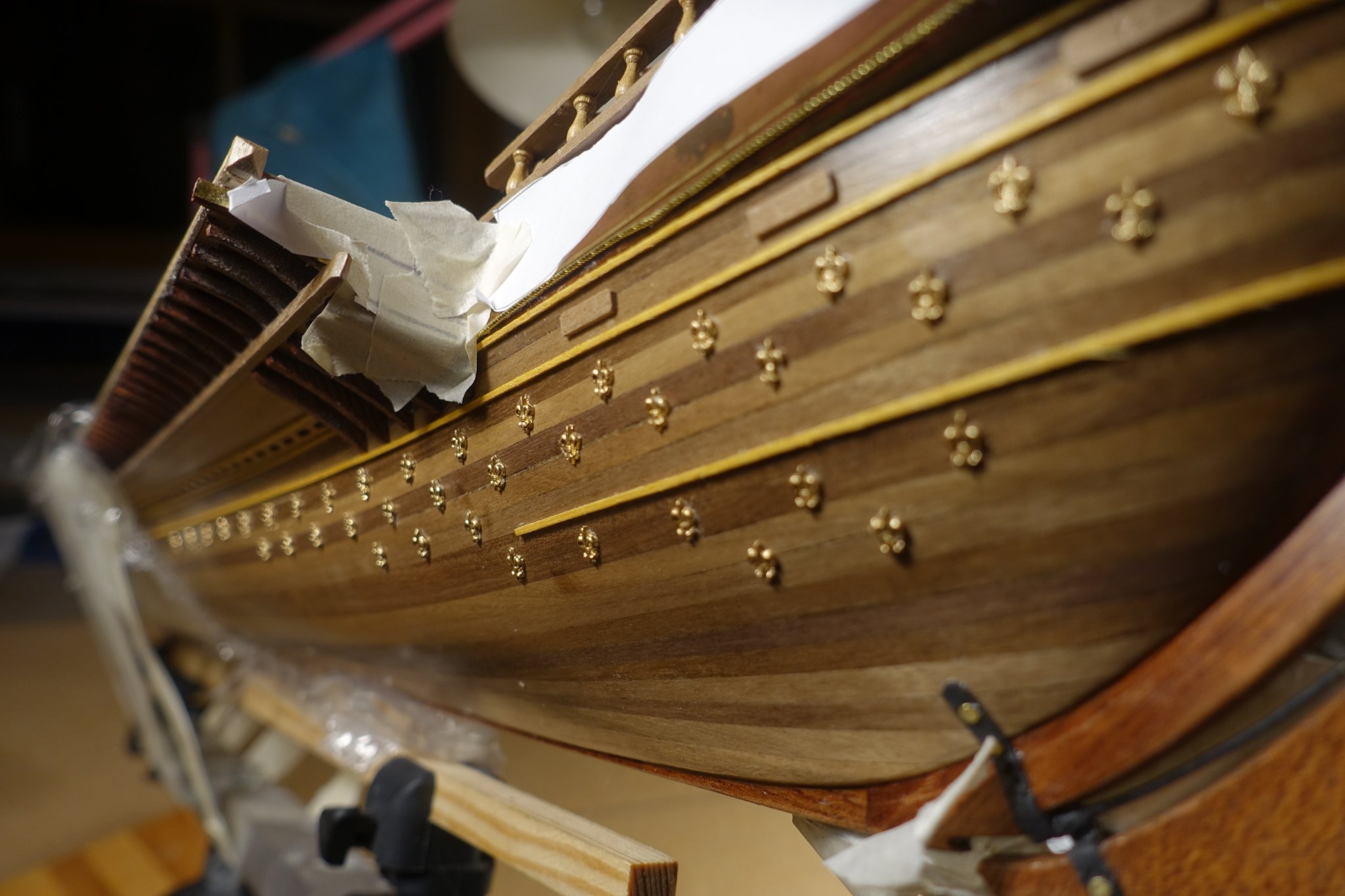
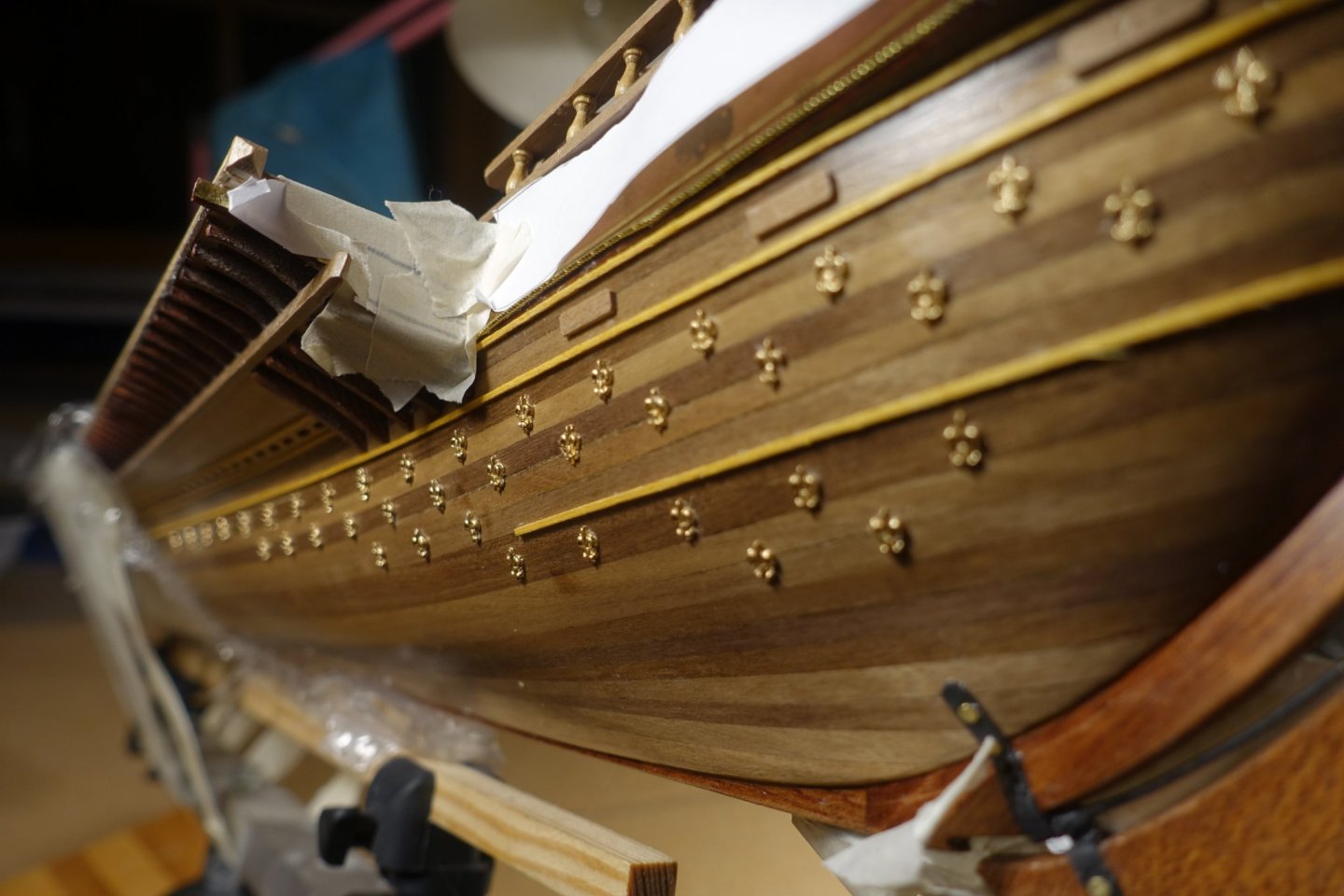
Hi Frank, it might be overkill but follows the picture below. Morever, I thought it would be a very nice contrast to the dark wood structure of the hull. I have shortly thought of blackening the ornaments but I finally painted them gold just to get the contrast. Gimo is surely right that they were painted directly on the hull but this is far beyond my skills. I fixed them with a gel-type CA glue. Some of the ornaments were carfully sanded on the backside to get an even surfeace to attach the glue. There is not a lot of time to correct the position. I have used several wood strips, horizontal and vertical, to mark the position. Woodstrips were cut using the ship waterline shown in the corelplan.
- 112 replies
-
- 4
-
-
- corel
- reale de france
- (and 1 more)
-
Lily ornaments were glued on the hull. When finished, there were only 3 lilies left. Thus, the further ornaments must be made in another way. I am quite sure that I did not drop any of the ornaments. But I had to sort out about 10 of them since they were not fully casted.
- 112 replies
-
- 3
-
-
- corel
- reale de france
- (and 1 more)
-
Thanks a lot Gimo, it really helps me. Thus, most of the force is transferred via the oarloops. If will probably simulate an additional leather protection between pin and loop. However, this will surely be some times later. At present I was wondering where to place the oar supports. Again thanks a lot Clark
-
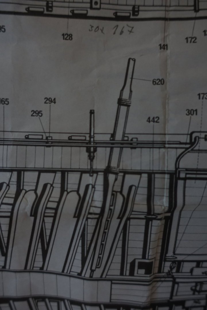
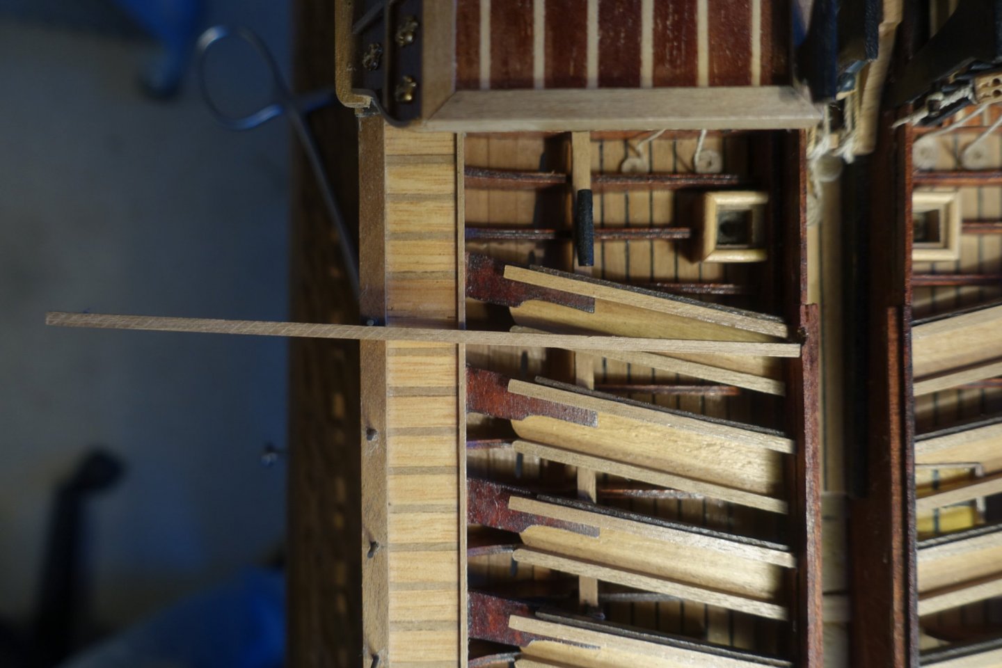
Hi Frank, just a short question. Hope you can help me. I am proceeding and started to place the oarlocks. But I was wondering about the Corel plan. It is shown that the oarlocks are on the stern side of the respective oar. I am quite convinced that they should be positioned on the bow side. Otherwise it would be impossible to transfer the force of the oarstroke onto the boat. I took a foto of the corel plan and simulated the correct (?) position of the oar in relation to the oarlock with a wood strip. I hope I could explain the problem. If yes, do you agree with me? Clark
- 510 replies
-
- 2
-
-
- reale de france
- corel
- (and 1 more)
-
I was also wondering about the hatches and followed the Corel plan. I will probly copy your hinge idea. Have a nice time with your family! Clark
- 510 replies
-
- 1
-
-
- reale de france
- corel
- (and 1 more)
-
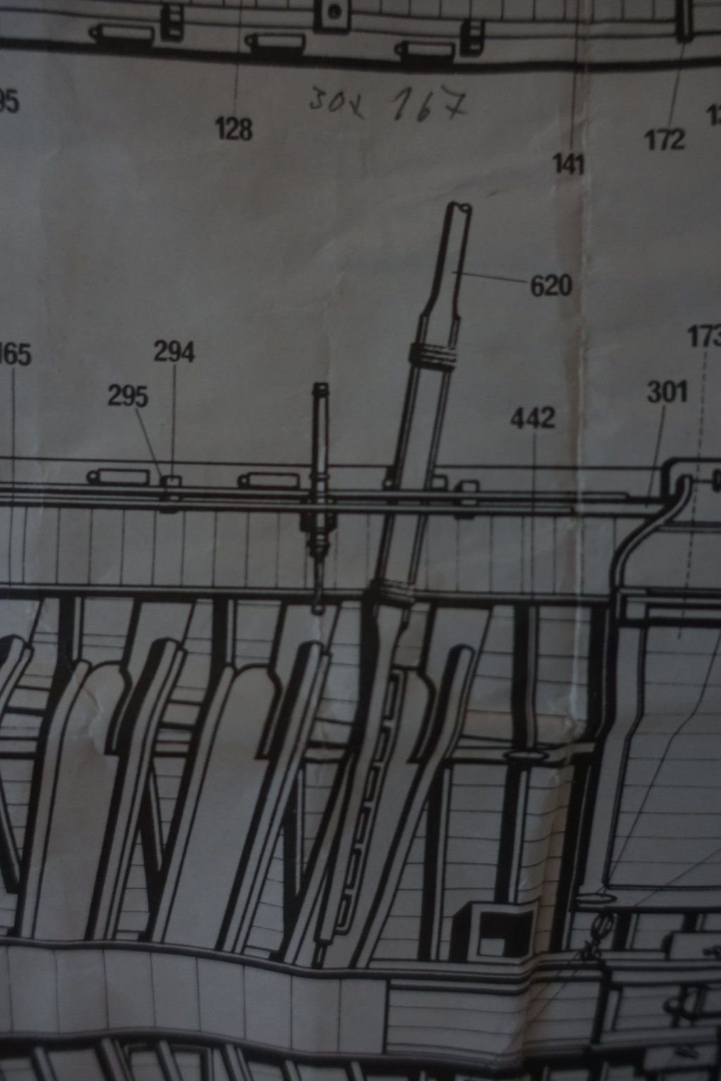
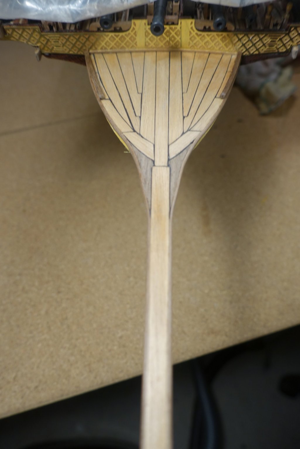
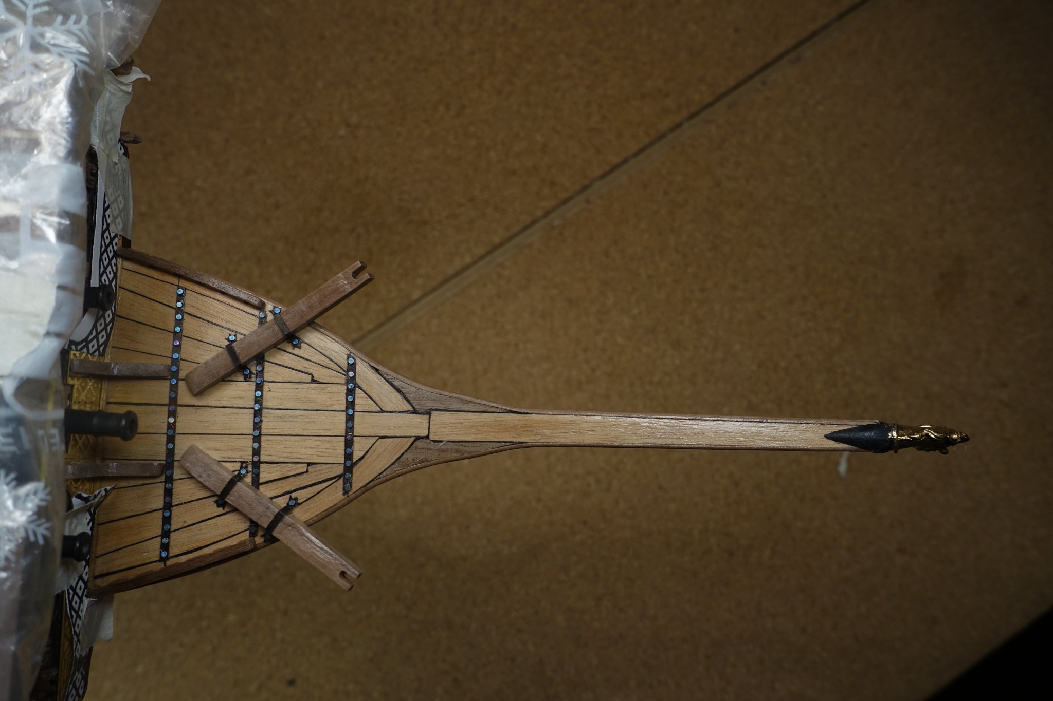
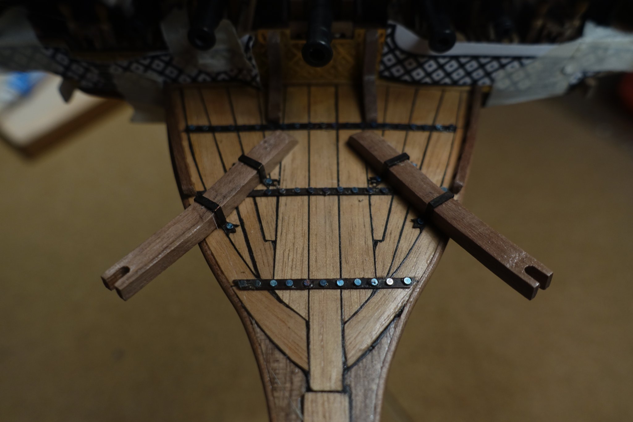
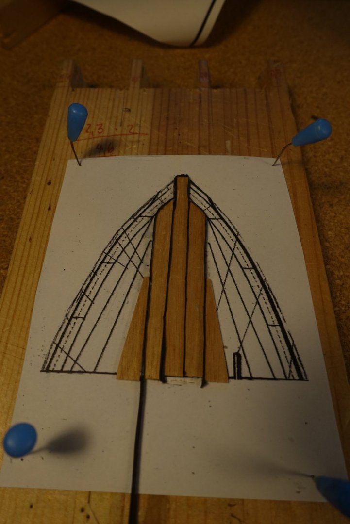
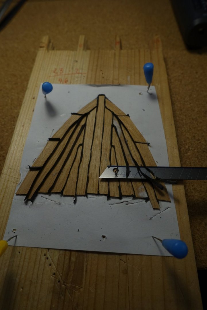
Planking of the bow area follows a certain pattern. After tracing the plank outline onto wood strips, planks were cut and glued onto paper. To simulate caulking, I used small strips of paper glued between the planks. Paper strips were cut when planks were glued. Planks were then sanded and glued on deck as a whole block. Knees, edges and rails were glued after sanding and smoothing the contour. Cathead material provided by Corel was slovenly prepared. Size differs (I noticed that after cutting the slots for the achor rope). At this point I was wondering if Corel really put enough effort to provide the wood material, since it is not the first time I noticed such an inaccuracy. Catheads were made new form walnut boards. Cathead and metal enforcement were added. Unicorn ram at the head was “stabilized” by a conical support.


- 112 replies
-
- 3
-
-
- corel
- reale de france
- (and 1 more)
-
Figurine looks excellent. Glad you managed the reattachment. Are you really sure you are able not to look at the ship for one week? Clark
- 510 replies
-
- 1
-
-
- reale de france
- corel
- (and 1 more)
-
Thanks a lot. Maybe such a long narrow ship is easier to steer than a short one. Like an eight-man sculls. Clark
- 112 replies
-
- 2
-
-
- corel
- reale de france
- (and 1 more)