-
Posts
2,638 -
Joined
-
Last visited
About JSGerson

- Birthday 11/04/1946
Profile Information
-
Gender
Male
-
Location
Aiken, South Carolina
Recent Profile Visitors
-
 mtbediz reacted to a post in a topic:
USS Constitution by GGibson - Model Shipways - 1:76.8
-
 mtbediz reacted to a post in a topic:
USS Constitution by GGibson - Model Shipways - 1:76.8
-
 GGibson reacted to a post in a topic:
USS Constitution by rvchima - Mamoli - 1:93
-
JSGerson started following USS Constitution by rvchima - Mamoli - 1:93
-
Welcome aboard! Although I'm constructing the MS model (with some kit bashing) I do have the pre-fire Mamoli plans & instructions and looked up the "clown" reference on my plans. It was not an error in translation, but poor printing. The correct word is "down" -> "Pin down on a flat wooden board ..." I don't know if you have researched any of the recent and past Mamoli builders of the Conny, but you might want to check BruceWayne426 in progress build and Bill Edgin's (Robnbill) completed build. It looks like you are off to a good start. I look forward to your future posts. Jon
-
 Der Alte Rentner reacted to a post in a topic:
USS Constitution by GGibson - Model Shipways - 1:76.8
-
 woodartist reacted to a post in a topic:
USS Constitution by mtbediz - 1:76
-
I don't know if it's the camera angle or what, but the gun barrel appeals to me to be low and not centered vertically between the lower framing and the top framing. The gun barrel must dead centered in the gun port. I had this same problem. I thought I had compensated for the gun deck with planking, but my guns sat too low. I never figured out where I screwed up. When it came time to actually install the guns, I found that the laser cut gun carriages that came with the kit did not match the US Navy drawings. They were shorter in height than the US Navy's. That is the reason I scratch built the gun deck gun carriages. Once fabricated, the new US Navy based carriages raised the cannon barrels enough to be at the proper height. Double check your measurements. Place a copy of the hull plans directly on your model to see if the gun ports line up. Maybe the gun deck planking will correct my perceived concern. Better safe than sorry. Jon
-
 GGibson reacted to a post in a topic:
USS Constitution by mtbediz - 1:76
-
 mtbediz reacted to a post in a topic:
USS Constitution by mtbediz - 1:76
-

USS Constitution by mtbediz - 1:76
JSGerson replied to mtbediz's topic in - Build logs for subjects built 1751 - 1800
Here you go: https://ussconstitutionmuseum.org/2017/04/20/springtime-for-uss-constitution/ Jon -
 mtbediz reacted to a post in a topic:
USS Constitution by mtbediz - 1:76
-

USS Constitution by mtbediz - 1:76
JSGerson replied to mtbediz's topic in - Build logs for subjects built 1751 - 1800
That is a great solution, I'll steal your idea and do the same thing when I get to that stage. Out of curiosity, the images of the of the bobstays on the actual ship appear to be photos made of images on a computer screen. Why didn't you use the original jpg file? If you don't have them, I do (of course I do 😁) if you want them. I can also provide the link to the source material they came from. Jon -
 mtbediz reacted to a post in a topic:
USS Constitution by Der Alte Rentner - Model Shipways - 1/76
-
 Thukydides reacted to a post in a topic:
USS Constitution by mtbediz - 1:76
-

USS Constitution by mtbediz - 1:76
JSGerson replied to mtbediz's topic in - Build logs for subjects built 1751 - 1800
That bowsprit is one complicated component and you fabricated beautifully. Well done!!! Jon -

USS Constitution by mtbediz - 1:76
JSGerson replied to mtbediz's topic in - Build logs for subjects built 1751 - 1800
Neat jig! Jon -

USS Constitution by mtbediz - 1:76
JSGerson replied to mtbediz's topic in - Build logs for subjects built 1751 - 1800
I would love to have that milling machine, but at this late stage of the build and my age ( I just turned 79 in November), I don't think I'll be building anything (if at all) nearly as challenging as this model that would require that tool, once my Conny is done. I do have an idea as to how to fabricate the stairs that would not require a milling tool as be as precise as yours ... I think. We'll see when I get there. In the meantime, I'm still plugging away at rigging the spar deck guns. Things should pick up pace once they are done. Jon -

USS Constitution by mtbediz - 1:76
JSGerson replied to mtbediz's topic in - Build logs for subjects built 1751 - 1800
Nicely done! But I have questions; don’t I always. When cutting the steps, I assume you “dialed in" the horizontal distance with the X-Y table to be precise and consistent. How did you measure the vertical distance? I don’t have a real drill press, just a Dremel drill press stand which does not have any controls for precise measured movement vertically. Are there any controls on your dedicated drill press or did you just use a ruler or micrometer? How did/will you mate the stairs to the bowsprit? Did cut a bevel on the underside of the stairs, or flatten the top surface of the bowsprit? If you beveled the stairs, how? Did you use a scraper or something else? Oh yes, don’t forget to provide a clearance notch under the stairs for the gammoning to pass through. Jon -
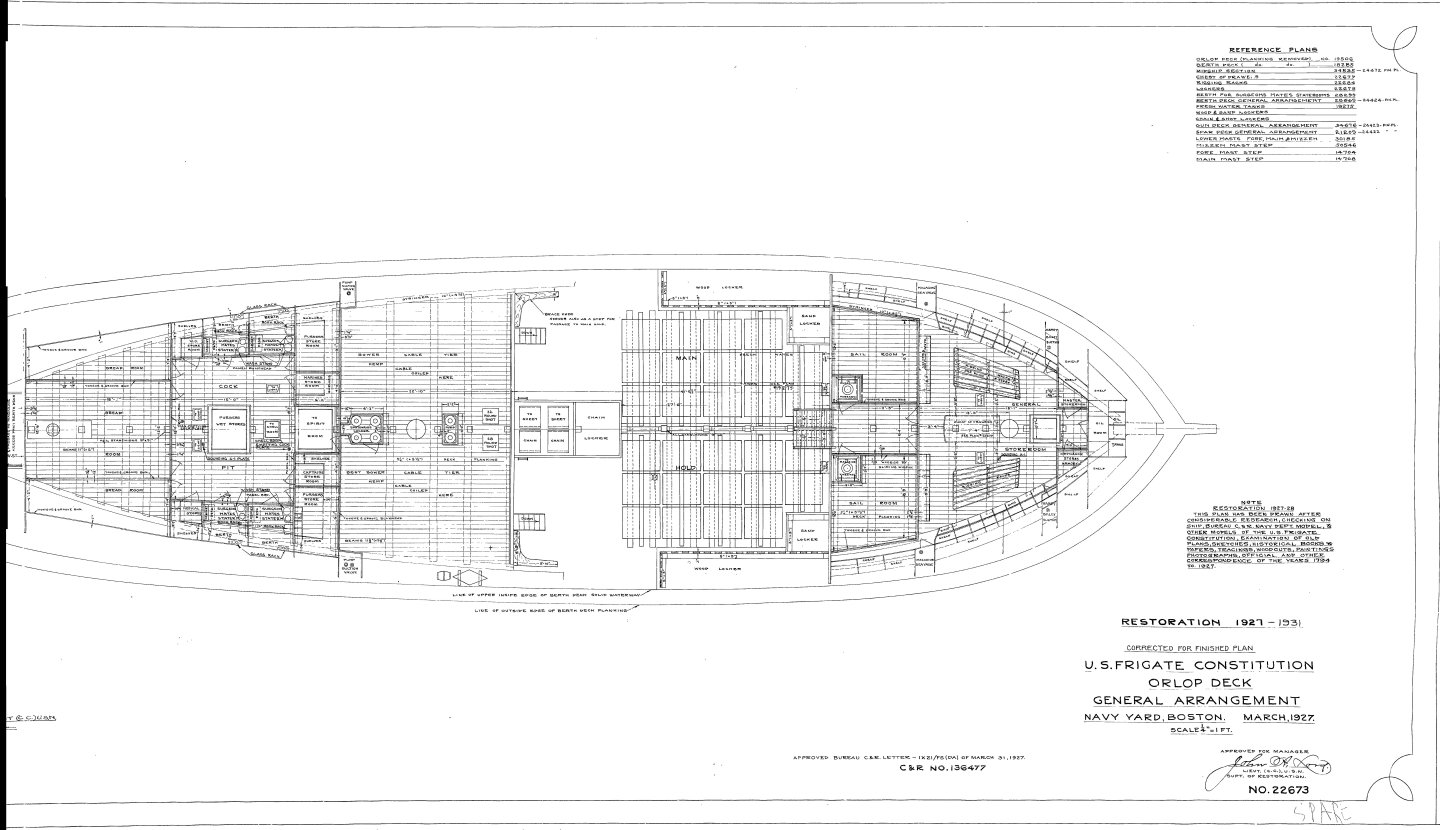
Heavy anchor chains were stored in the chain locker, located beneath the orlop deck (the lowest deck) and forward of the mainmast, in the bow section where the anchor chains would run down and coil when brought aboard. The rope cable or chains length varied but were about several hundred feet long. See attached plan. On my model, I have both a cable and a chain traveling from the hawsers along the gun deck and down into pipes leading down into the chain locker. Jon
-

USS Constitution by mtbediz - 1:76
JSGerson replied to mtbediz's topic in - Build logs for subjects built 1751 - 1800
Thank you. You made a complicated rigging element look simple. Again, well done. Jon -

USS Constitution by mtbediz - 1:76
JSGerson replied to mtbediz's topic in - Build logs for subjects built 1751 - 1800
They look beautiful! You didn't perhaps take pictures showing the sequence of steps you took to get the Bentinck shrouds into the state shown? Are the short shrouds sections coming off the the futtock stave, looping in the big ring or are they individually tied off at the ring? I understand your choice to omit some fine details due to scale; at full scale, there is an awful lot stuff crammed in there. But whatever you did, it look great. Jon
About us
Modelshipworld - Advancing Ship Modeling through Research
SSL Secured
Your security is important for us so this Website is SSL-Secured
NRG Mailing Address
Nautical Research Guild
237 South Lincoln Street
Westmont IL, 60559-1917
Model Ship World ® and the MSW logo are Registered Trademarks, and belong to the Nautical Research Guild (United States Patent and Trademark Office: No. 6,929,264 & No. 6,929,274, registered Dec. 20, 2022)
Helpful Links
About the NRG
If you enjoy building ship models that are historically accurate as well as beautiful, then The Nautical Research Guild (NRG) is just right for you.
The Guild is a non-profit educational organization whose mission is to “Advance Ship Modeling Through Research”. We provide support to our members in their efforts to raise the quality of their model ships.
The Nautical Research Guild has published our world-renowned quarterly magazine, The Nautical Research Journal, since 1955. The pages of the Journal are full of articles by accomplished ship modelers who show you how they create those exquisite details on their models, and by maritime historians who show you the correct details to build. The Journal is available in both print and digital editions. Go to the NRG web site (www.thenrg.org) to download a complimentary digital copy of the Journal. The NRG also publishes plan sets, books and compilations of back issues of the Journal and the former Ships in Scale and Model Ship Builder magazines.


