JSGerson
-
Posts
2,618 -
Joined
-
Last visited
Content Type
Profiles
Forums
Gallery
Events
Everything posted by JSGerson
-
 Only 5 years? I'm into mine 8 years and am now just starting the spar deck. I figure another 3 years for me.😏 Jon
 -
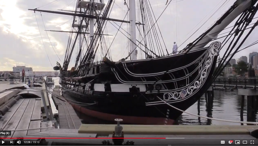
Peter, I have said many times on other build logs, that Mr. Hunt never fully built his Constitution model, but just enough to show how it should done. He also skipped some details and not others. In the case of the bow top gallant bow, he messed up. As you pointed out on his model, the flair on either side of the top bow gallant rail is missing. And what isn't missing should be, specifically the space above the bowsprit as it passes through the rail. Mind you, I'm not putting down his practicum, it's got a lot of good stuff but it's not the end all reference. Always, always check the actual photos when you can. And if you can't find photos, ask me, I might have what you are looking for. Jon
-
OK, now we know that Mustafa is building the 2015 version (no top gallant rail except for the bow), you are building the 1927 version (top gallant rail all around), and I'm building the present day version (no top gallant rail at all) of the USS Constitution. The other two most common versions are 1797 launch and the War of 1812. This is why I have always said you must decide what era you are modeling right at the beginning of your build and stick to it. Note, the MS kit is based on the 1927 restoration and BlueJacket and Revell are based on 1812. I don't know what the others (that I know about) are officially based on (Mamoli, Mantua, Constructo, Billing Boats, and Scientific). Jon
-
I've have never molded anything, but I'm sorry, nothing is "fairly easy." There must be a bunch of details that must checked everything must be set just right to obtain the optimum results. You did good. You proved casting the part is an art and the painting of the part's fine details was wonderfully done. You sir, are an artist! How did you do get those painting results? Your brush must of had just one hair😁 Jon
-
My fears are allayed, it looks great. Jon
-
USS Constitution by mtbediz - 1:76
JSGerson replied to mtbediz's topic in - Build logs for subjects built 1751 - 1800
Now why didn't I think of that. Great solution! Jon -
Beautiful and the rigging securing the boat to the the hatch is nice and clean. Well done! Jon
-
Nice save. My only concern is when you stain the wood, the stain may accentuate the break lines. In hindsight, I might have started over and drilled the holes starting with a very small diameter and working my way to the target size with larger and larger drill bits or round files. Small pieces of Basswood are quite fragile, so maybe a harder wood like boxwood might have helped. I realize this advice is a bit late now, but hopefully, may be useful in the future. Jon
-
Peter, while perusing the Ships of Scale site, I ran into a general broadcast for someone who lives in South Carolina, who would be willing to go to Charlestown SC area, specifically Patriots Point Maritime Museum to photograph some Dahlgren Guns which are on display. He wants to build a 1/10 scale model of one of the guns but didn't have any good photographs of them. He lives in Australia, so going there himself would pf been a bit of an effort. I decided that it would be a nice day trip for me, so I did as he asked. He was very happy with my pictures and said to watch his website when he starts the project. I looked at his site and discovered that he completed a model of the USS Constitution in natural wood like you. Although his is a Mamoli model, I thought you might be interested. His name is John Viggars at Johnsmachines.com. Scroll down to May 4, 2024 "Unboxing for Grandfathers." Jon
-
USS Constitution by mtbediz - 1:76
JSGerson replied to mtbediz's topic in - Build logs for subjects built 1751 - 1800
It loaded just fine for me -
USS Constitution by mtbediz - 1:76
JSGerson replied to mtbediz's topic in - Build logs for subjects built 1751 - 1800
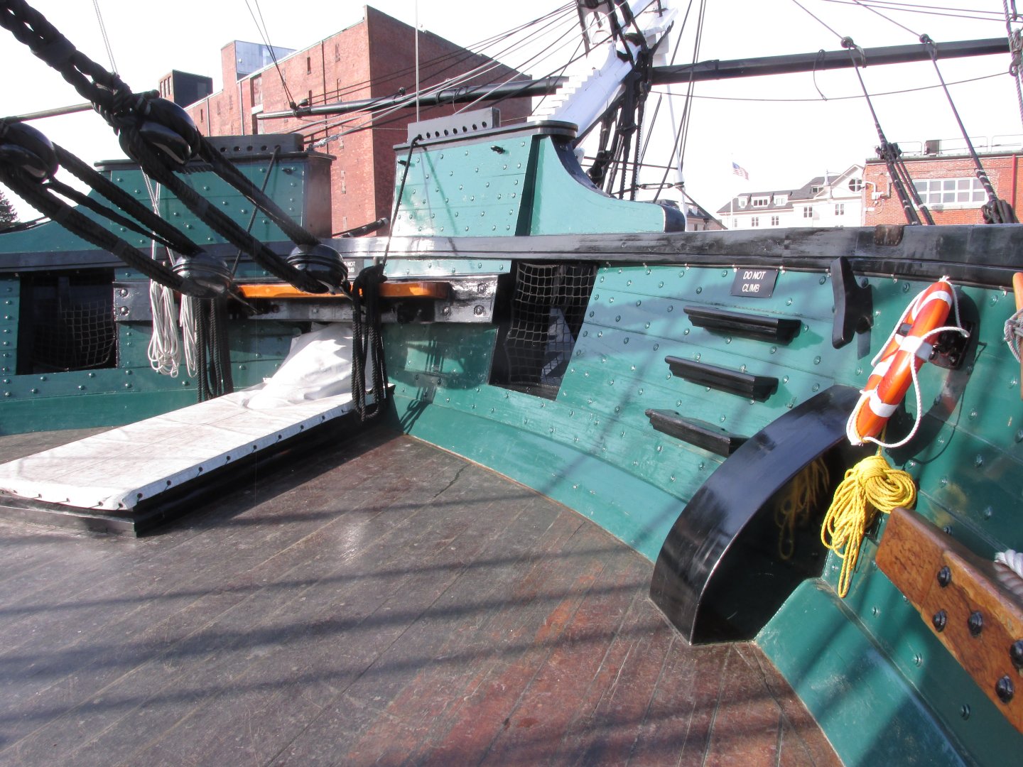
The ship gets a restoration, large or small, about every 20 years or so. Copper is replaced, wood repaired, and sometimes structure is modified. As I understand it, and I may be wrong, the 1927-31 restoration made some changes that were not correct. The wrong model of carronades is one example and the addition of the topgallant rail, now completely removed, is another. Slowly, the ship will be restored to look more like she did in 1812... I think. Whether they will change the transom, the most obvious transformation in the future, who knows. Jon -
USS Constitution by mtbediz - 1:76
JSGerson replied to mtbediz's topic in - Build logs for subjects built 1751 - 1800
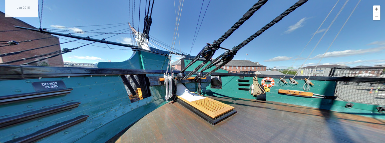
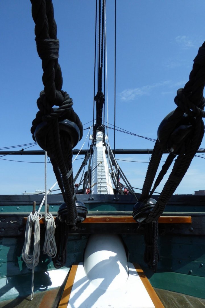
Wow, I really kicked a hornet's nest, resulting in these conversations since I turned off the computer last night. It's now the next morning, Yes, the 3D tour took place in 2015, before the last restoration where the bow topgallant rail was removed. So now Mustafa, you are officially locked into 2015 as the era of your model. Yes, the carronades on the the actual ship are incorrect except for the two with the screw elevation control. I plan on installing the screw type for ALL the carronades on my model. Will see how that goes when the time comes. Remember, you are the captain of your ship and you determine what it should look like. Jon -
Looks good to me! Jon
-
USS Constitution by mtbediz - 1:76
JSGerson replied to mtbediz's topic in - Build logs for subjects built 1751 - 1800
Beautifully done as I would expect. I have only one comment. Some time ago you mentioned that your model is based on what the real ship looks like TODAY. However, and I really hate to mention this as it would mean changing what you just did, today's ship does NOT have the bow topgallant rail ("bow rail") anymore since the ship's last restoration in 2015-17. Of course I could be wrong in your intensions; I do hope I'm wrong. Jon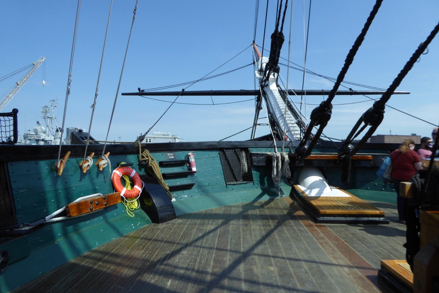

-
Unegawahya - Tenacity, sheer unmeditated tenacity is all it took. Jon
-
USS Constitution by mtbediz - 1:76
JSGerson replied to mtbediz's topic in - Build logs for subjects built 1751 - 1800
Nice, clean, and precise...your usual excellence! Jon -
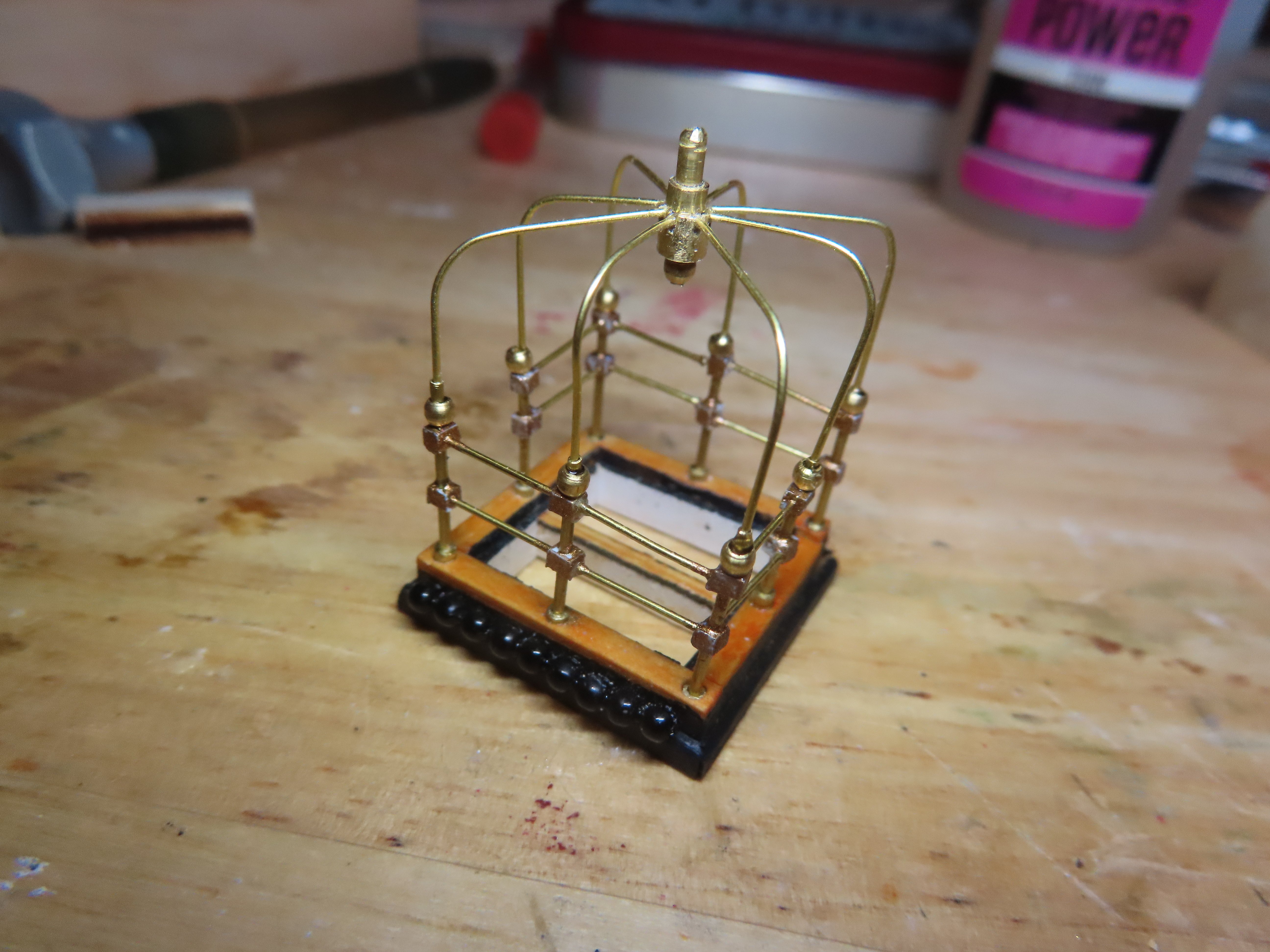
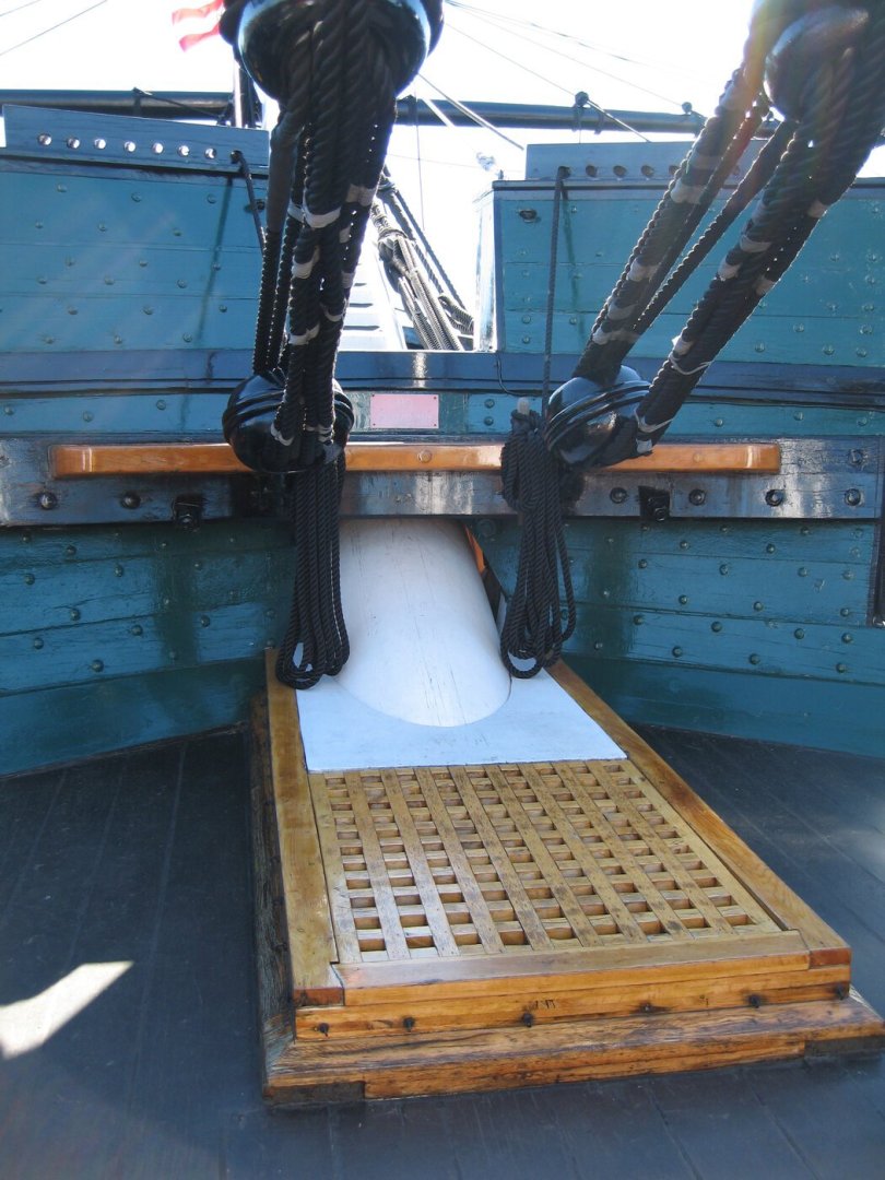
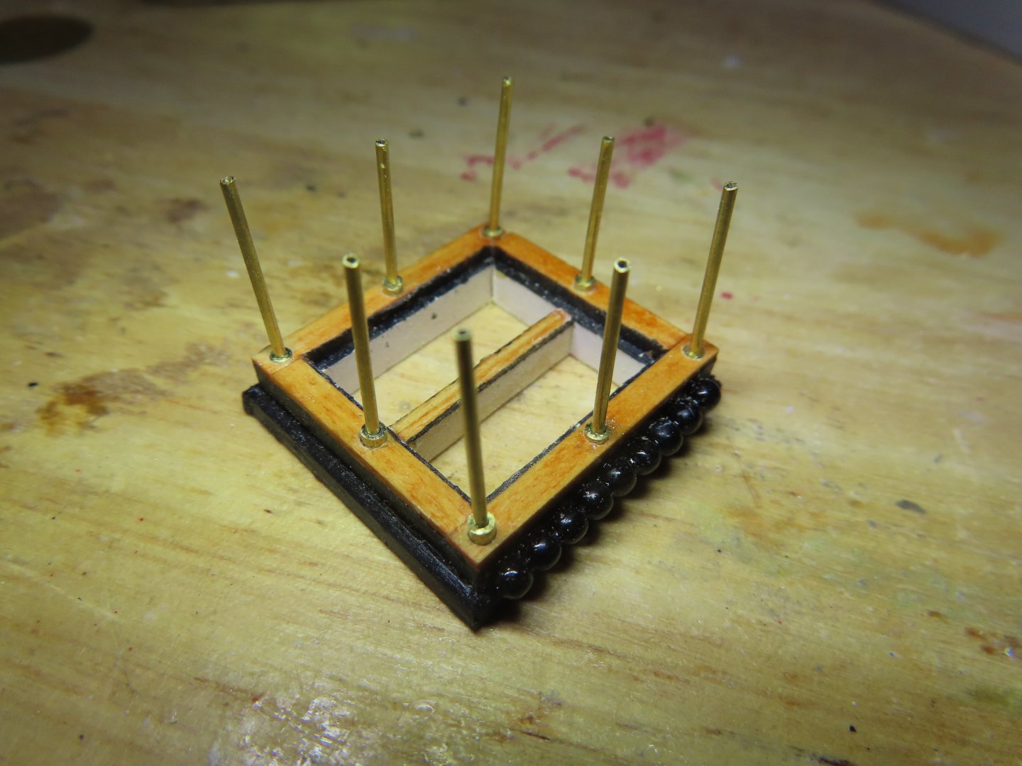
The second canopy frame is completed in one month, half the time it took me for the first one. This is one of the pairs of hatchways at the ship’s wheel. The other one is closed and therefore has no frame. The last two are on the main hatchway. They are a bit smaller and have only seven stanchions each. Jon

-
I know you asked this question to Geoff, but I thought I would throw in my two cents. I've always felt that the eye bolts supplied by Model Shipway were for the most part, too big for the scale of the model. Some years ago I found on eBay, Model Shipway supplied 1/32" brass eyebolts sold in a 1,000 items per bag. A 1/32" eyebolt is about 2.4" scale (1:76.8). I have used just about every one of them. Unfortunately, I could not find that deal again. But I have found from various vendors the 1/32" eyebolts both in brass and copper but sold in smaller units. For me, they are a must have item. I suggest that you have a supply of these as they will be very handy to have. Jon
-
USS Constitution by mtbediz - 1:76
JSGerson replied to mtbediz's topic in - Build logs for subjects built 1751 - 1800
I would love to have the dividing attachment, but for the cost and the amount of times I could use it in the future, I can't justify the cost. That and the fact my Dremel drill stand is not what you would call a precision instrument. Setting up the X-Y table on the drill stand is a pain because it's held in place with clamps and alignment is done by eyeball and trial and error. As for the draw plate, I got mine from Byrnes Machine Tools and it was worth every penny. I bought it because the drawplate had from Micro-Mark just wasn't a precision tool especially for the fine holes. I've learned not to buy tools before I need them, because invariably, I didn't need them. The other side of the coin is not having the tool when you need it and it's too late to buy it, like the dividing tool. I wish you well on you new acquisitions. Jon -
USS Constitution by mtbediz - 1:76
JSGerson replied to mtbediz's topic in - Build logs for subjects built 1751 - 1800
I really wanted the canopy to have the center ornament that others had made. I committed myself and I will finish them before the decade is done🙃! Jon -
USS Constitution by mtbediz - 1:76
JSGerson replied to mtbediz's topic in - Build logs for subjects built 1751 - 1800
Well done. I would have never have thought of fabricating the binnacles in that manner. Since I don't have a true drill press, just my Dremel drill stand and a Proxxon X-Y table, I'll have to give some thought as to how I could successfully accomplish the same thing as you (alignment issues) when the time comes . That is, if I ever finish these #$%^& canopy frames.🤬 Jon -
USS Constitution by mtbediz - 1:76
JSGerson replied to mtbediz's topic in - Build logs for subjects built 1751 - 1800
Still, Wow! -
USS Constitution by mtbediz - 1:76
JSGerson replied to mtbediz's topic in - Build logs for subjects built 1751 - 1800
Wow! -
USS Constitution by mtbediz - 1:76
JSGerson replied to mtbediz's topic in - Build logs for subjects built 1751 - 1800
Out of curiosity, how did you set up your soldering jig for the skylight railing? Jon -
USS Constitution by mtbediz - 1:76
JSGerson replied to mtbediz's topic in - Build logs for subjects built 1751 - 1800
Compared to mine, your skylight is simpler to construct and just as visually effective if not more so. Excellence job in placing those horizonal brass bars. That was not easy to do. Breath wrong or have a slight hand tremor, and it's messed up. Well done. Jon