JSGerson
-
Posts
2,646 -
Joined
-
Last visited
Content Type
Profiles
Forums
Gallery
Events
Everything posted by JSGerson
-
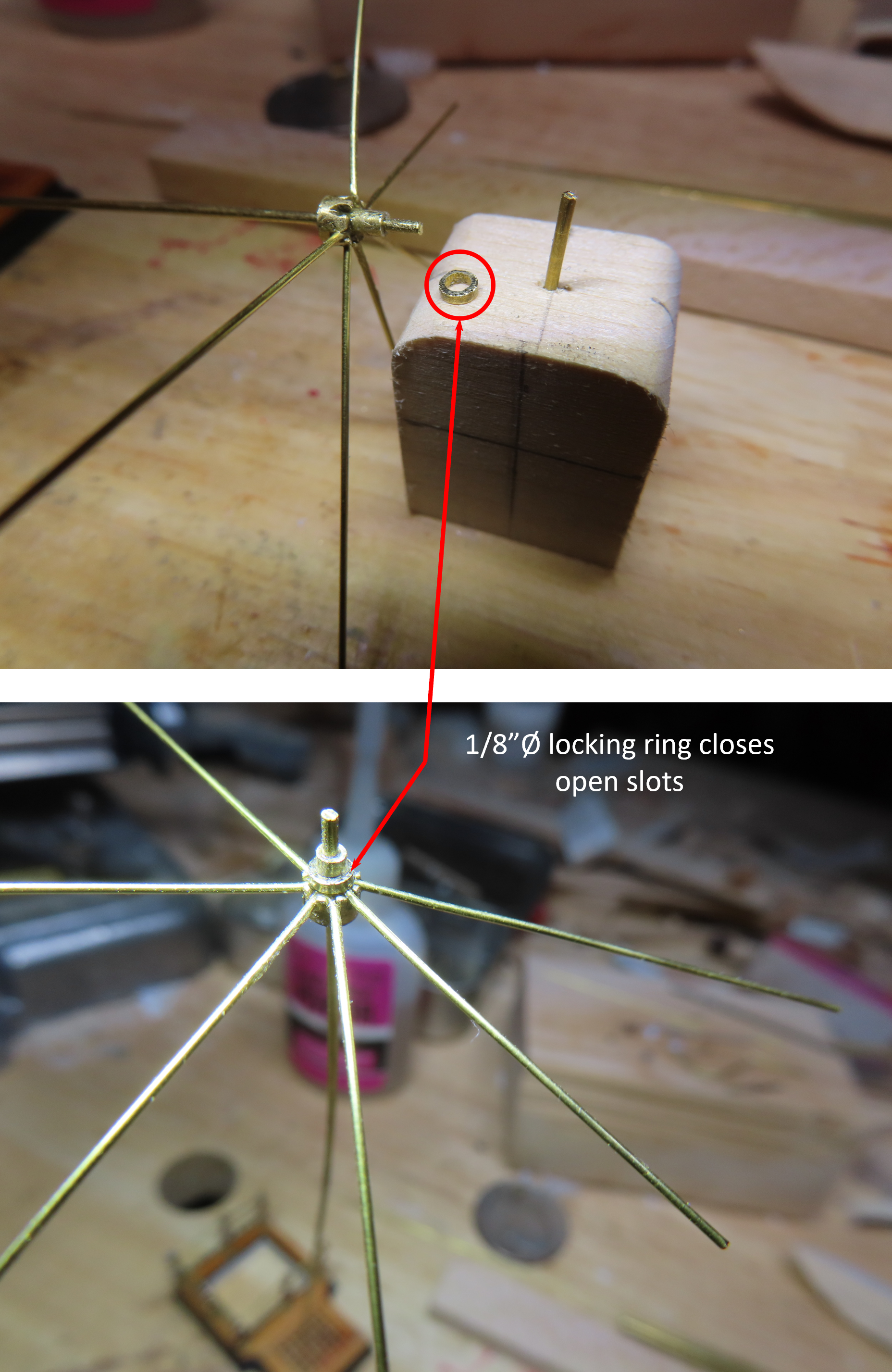
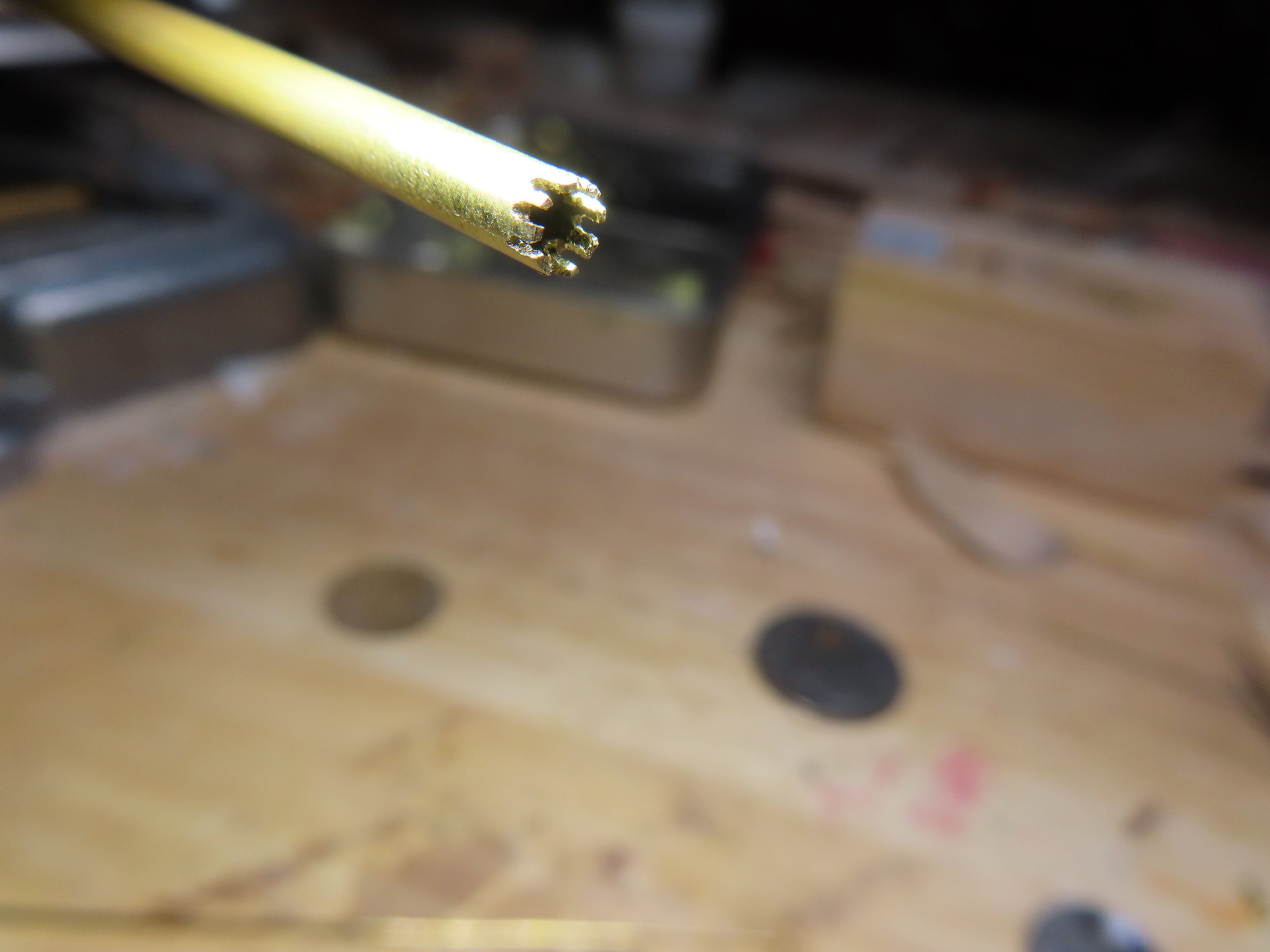
 To complete the mechanical hub structure, a locking ring was cut from the 1/8ӯ tube and fitted over the slots converting the slots into holes and locking the supports to the hub.
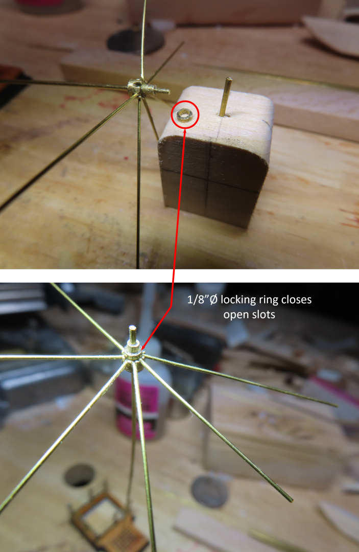
-
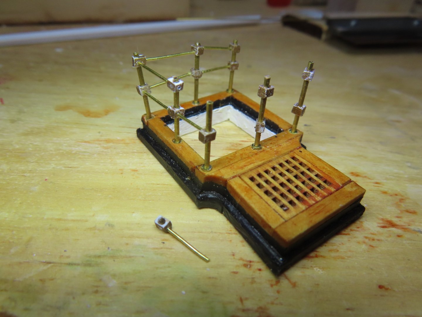
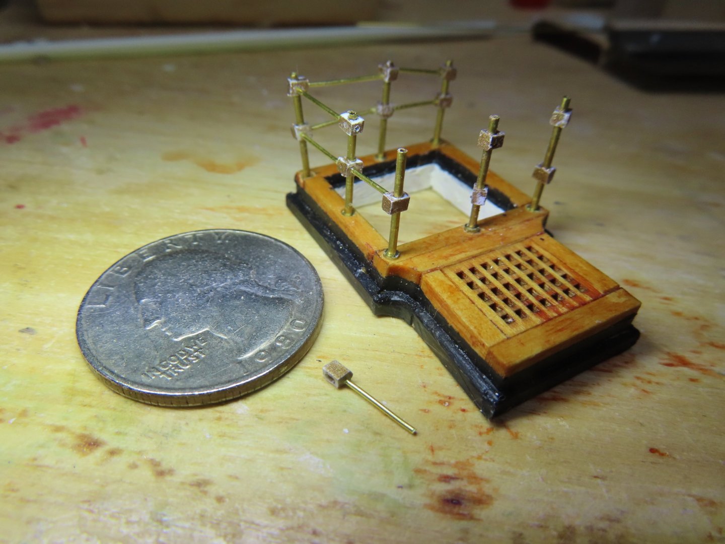
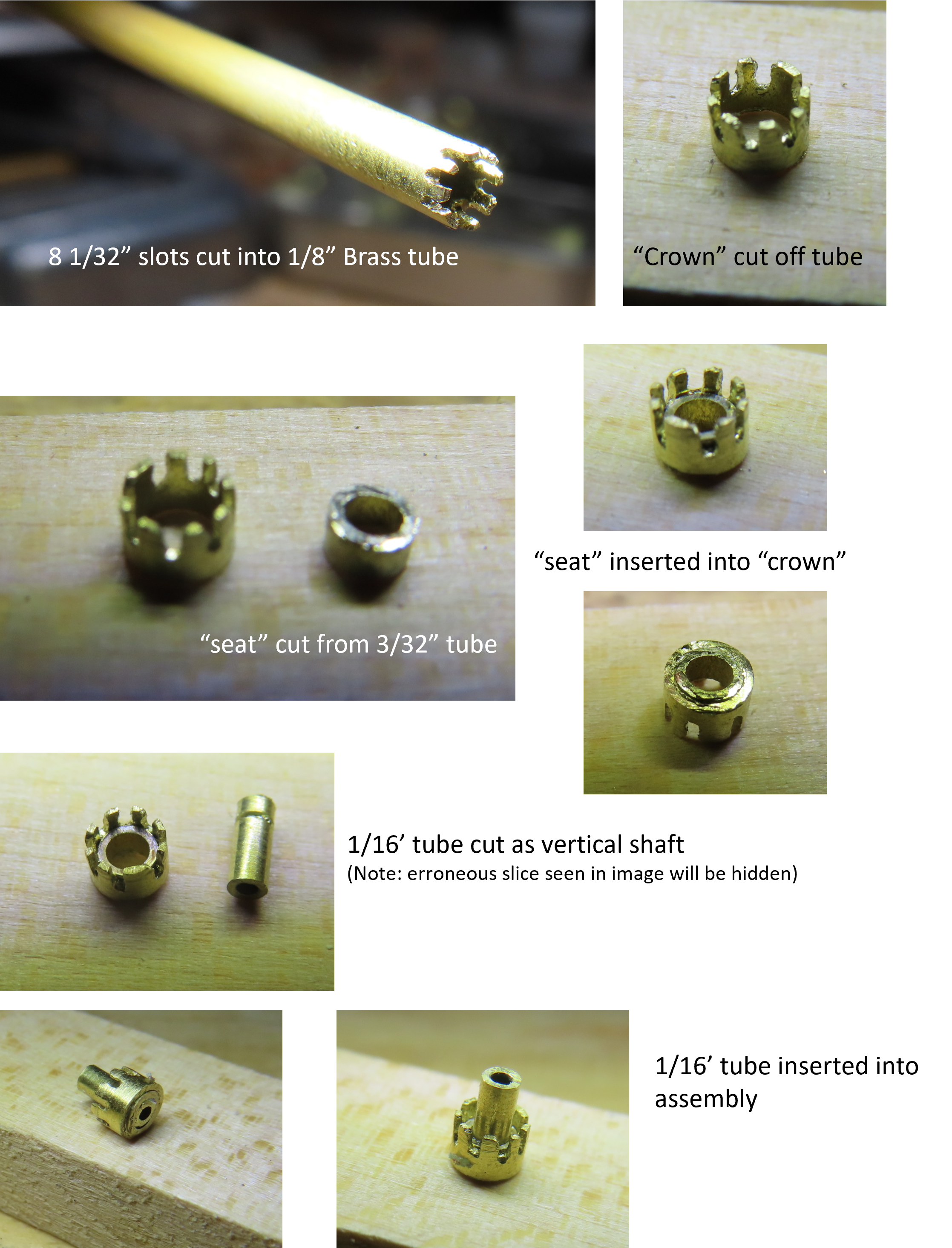
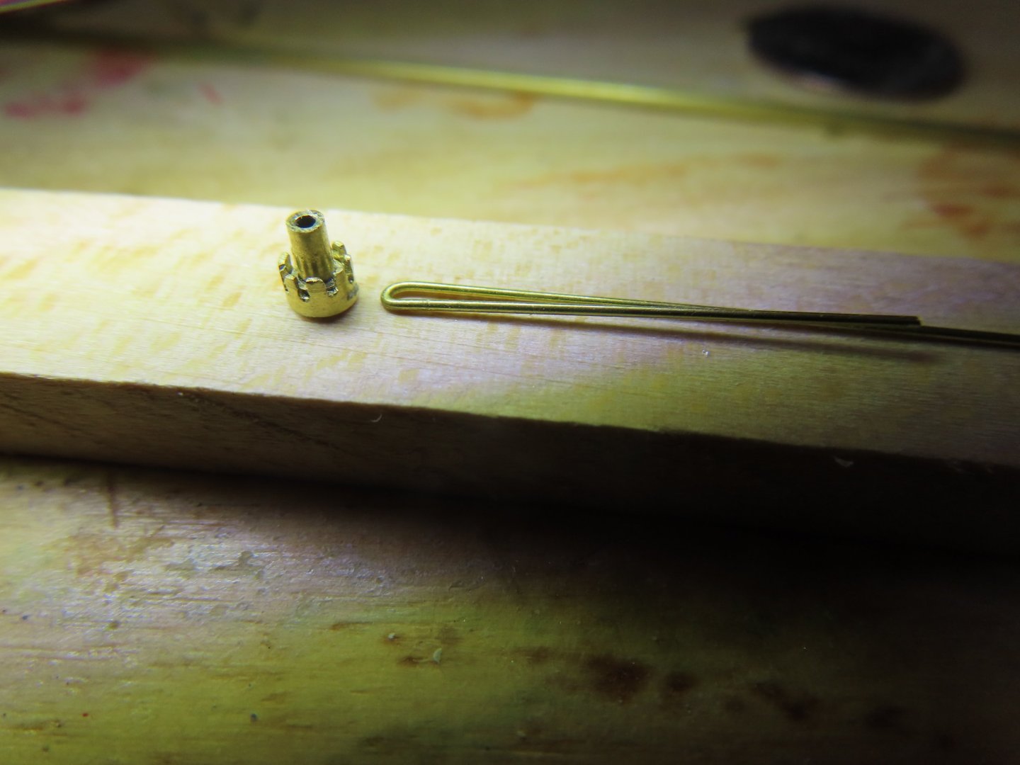
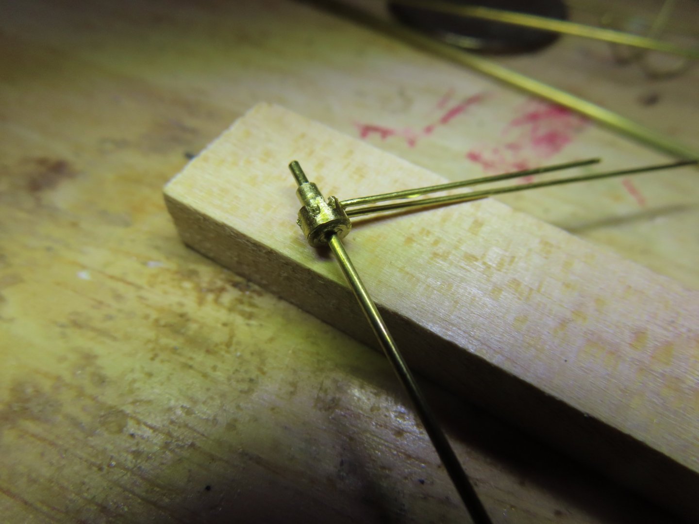
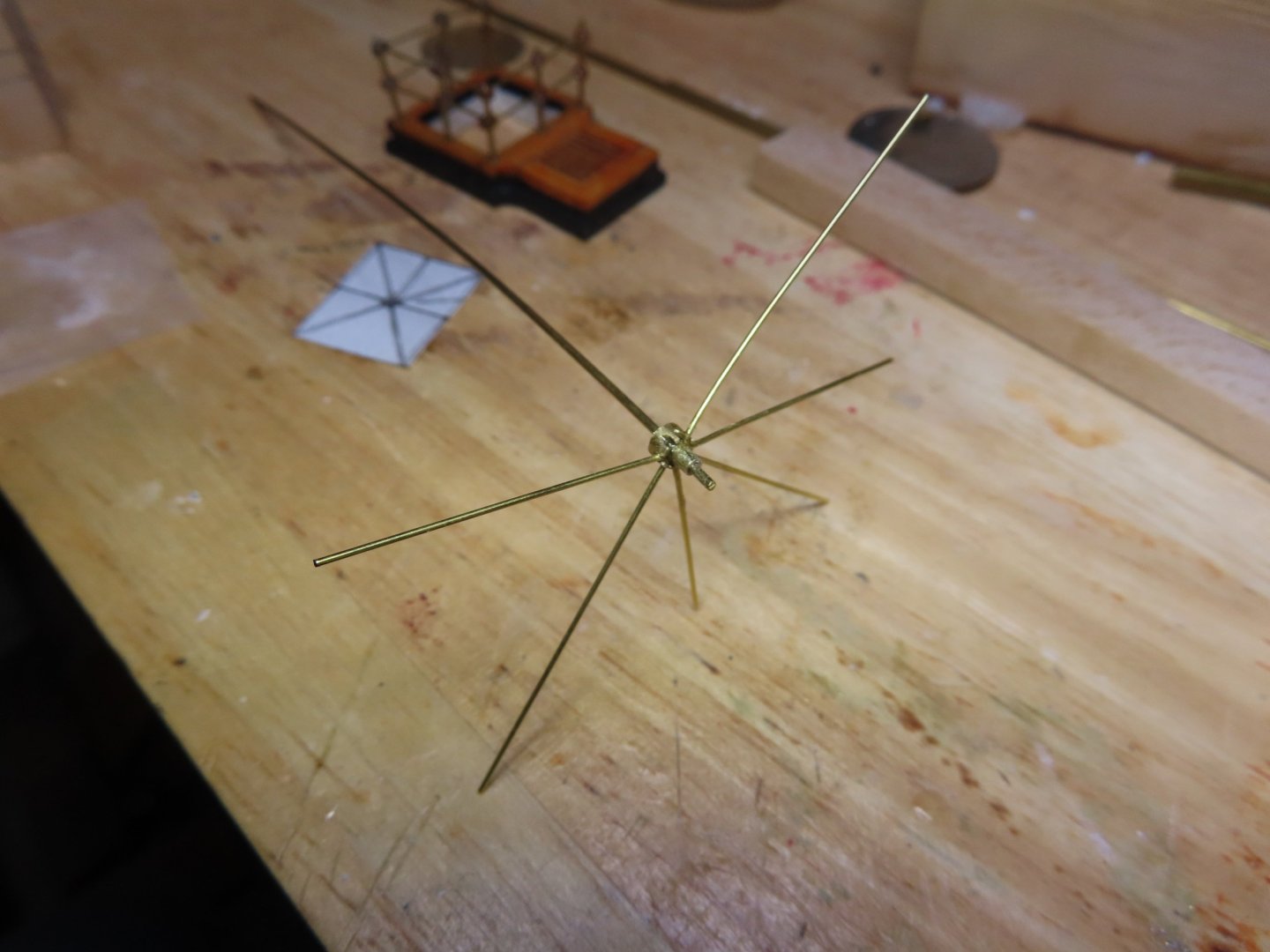
A length of 2 3/8” 0.020” brass rod was cut and bent so that one leg was 1” and the other 1 3/8” for the two supports lengths of the frames. This is a bit more than was needed, but it is easier to cut off excess than extend a short leg. Three pairs or 6 supports were created, however, this canopy required 7 supports. The last support (non-pair) was planned to be added once the canopy was assembled. At that point the seventh support will slide into the remaining opening in the hub and be glued into place. A length of 1/16”Ø brass tube was inserted into the hub assembly as a “working” handle. As each pair of supports was added to the hub, it was secured by CA glue.
-
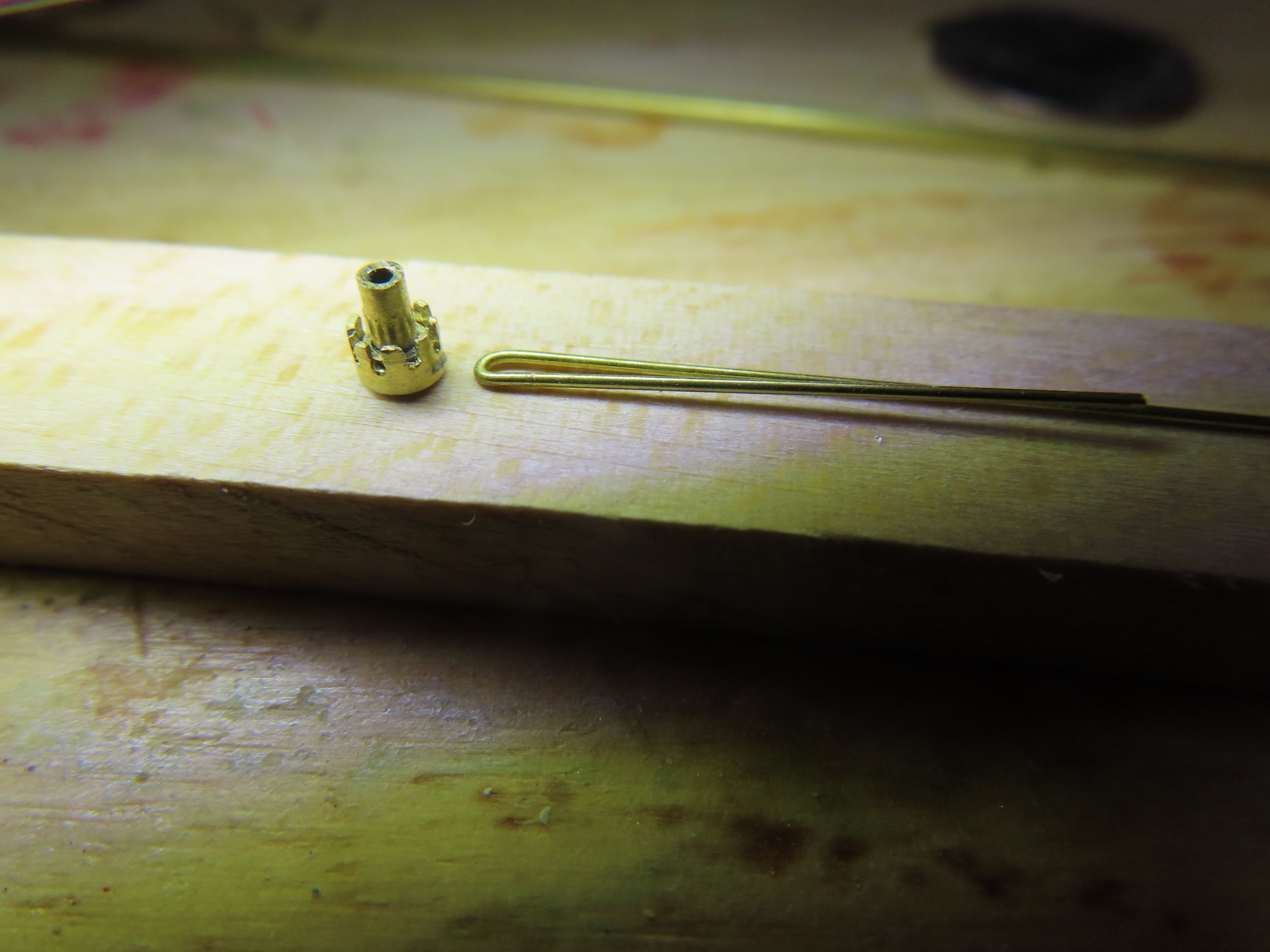
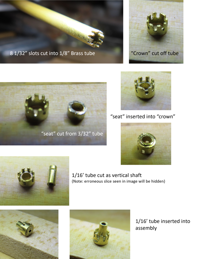
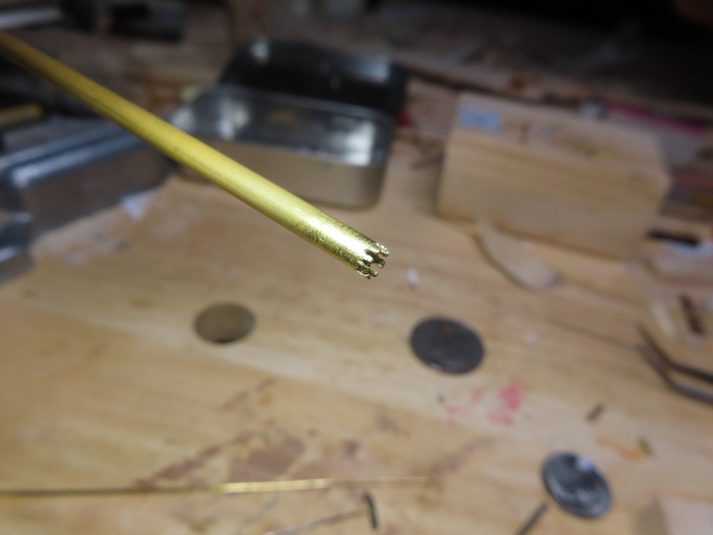
The end of the 1/8” tube was sawed off, producing a 1/8”Ø “crown” shaped component. Next, a slice of 3/32” tube was cut creating the seat ring, which was inserted into the bottom of the “crown.” Inside of that, a length of 1/16” tube was inserted creating the inner wall and axial of the hub assembly. Following the plan, additional pieces were added to create the hub.
-
The trick here is cutting the brass slots to accept 0.020” Ø brass rod. My fine-tooth miter hand saw is 1/128” (0.008”) thick, cutting very narrow slots. The slots were 1/64” too narrow and my files were too thick to fit in the cut slots to widen them. Using various drill bits in my variable speed Dremel at the slowest setting, the slots were widened by sliding the spinning drill bit up and down the slot cutting with the bit’s side. Sorry, I could take a picture of this, as I needed both hands to perform this procedure.

-
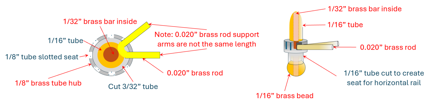
Fifth Attempt Ok, let’s be more pragmatic and increase the diameter of the hub to 1/8”Ø and sacrifice a bit of scale. If I’m going to do that, I can also discard the styrene for the hub material and come full circle and use brass tube once again. Since I won’t be drilling holes, (the reason for the plastic in the first place), but cutting slots, I’ve eliminated the brass holes problem.
-
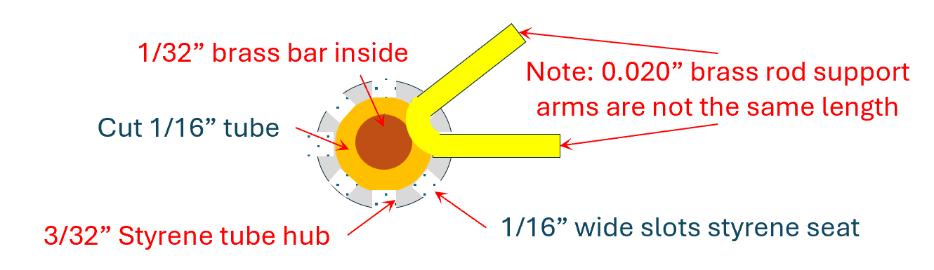
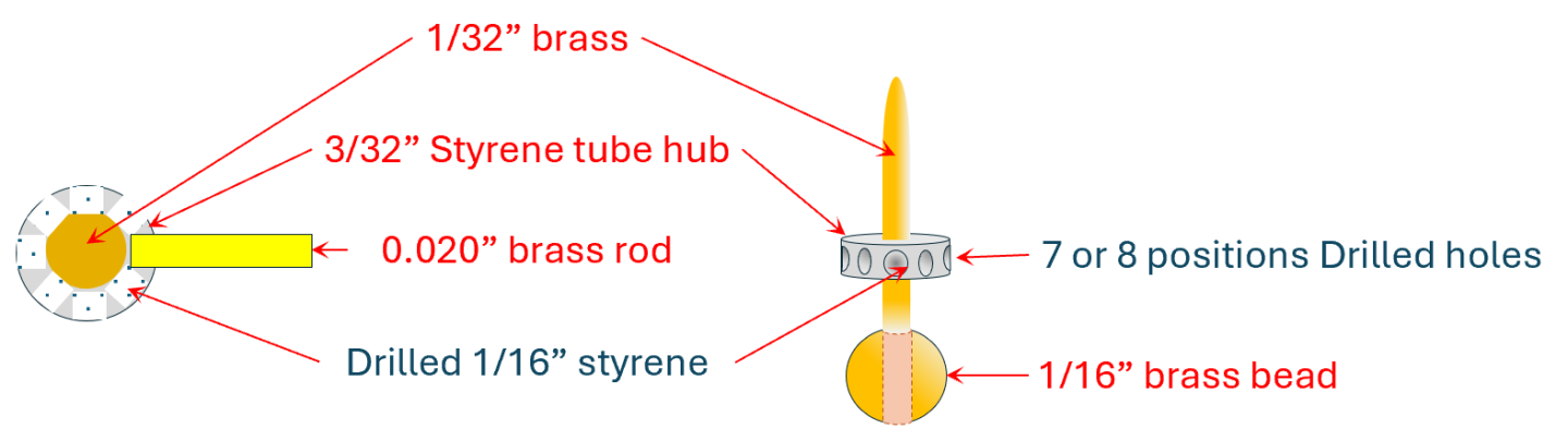
Fourth Attempt The next development was the idea to make a double support such that the brass rod would pass into the hub and back out through a difference opening as a second support. This would mechanically fasten the brass rod to the hub. To do this, I would have to change the drilled holes in the hub to vertical slots so the brass rod could be dropped into the openings. It’s not like the rod can act like a piece of string that can be threaded. This introduced a new problem. Once the holes in the styrene hub were converted to vertical slots, the remaining vertical styrene material was now narrow, flexible, and weak and would break off should anything tug on them…like the brass canopy rods. Additionally, more room is needed to accommodate the bends.
-
Third Attempt My next idea would be to cut the 1/16” Ø brass tube leaving the 1/32” Ø rod alone uncut. Now there would be two 1/16” Ø brass tubes one on top of the other with a gap in between, wide enough to accept the 0.20” brass rods. This expose tube wall would extend the rail seat another 1/64”. Mechanically, it is slightly stronger than the previous idea, but still fragile. And how does one assemble 7 to 8 spokes into the hub and hold them in place precisely to glue them together with sufficient strength?
-
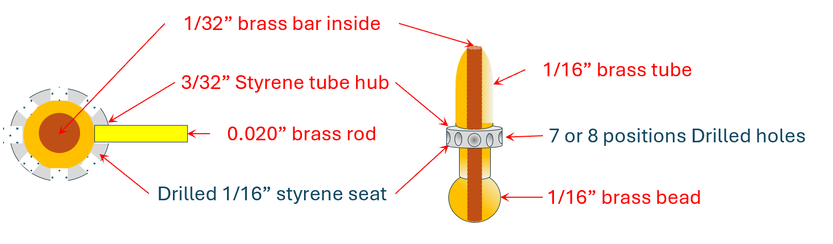
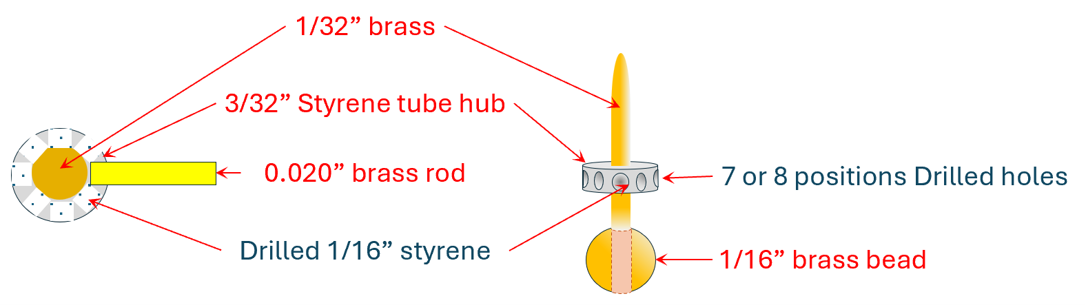
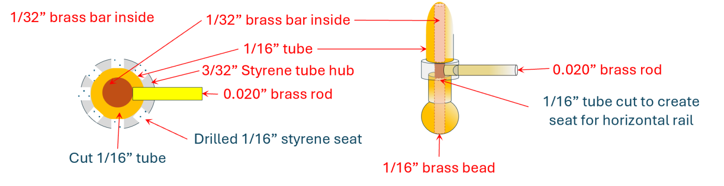
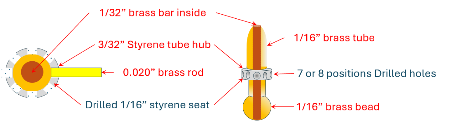
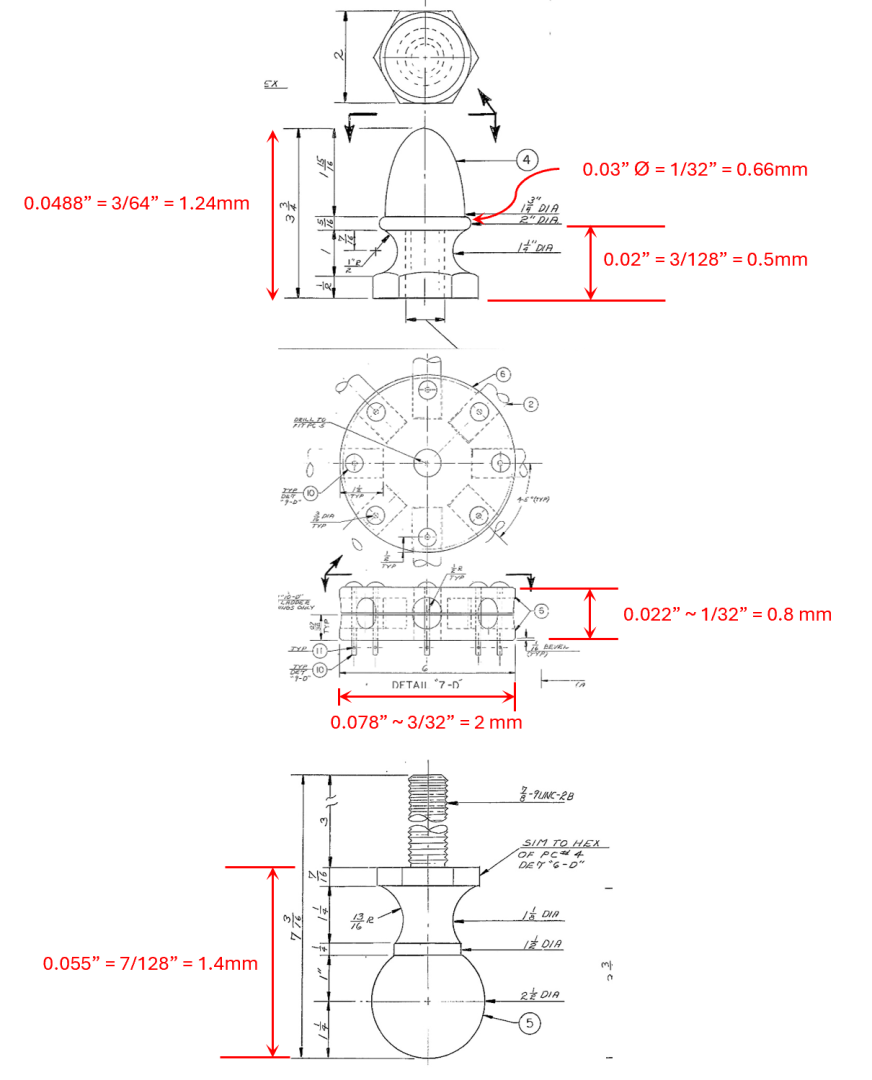
Second Attempt I was forced to make a small dimensional compromise. The top part of the full-scale ornament is 2” in diameter which scales down to 0.03” (1/32”). This had to be enlarged to 1/16”Ø due to fabrication practicality. At the center of the hub, is the ornament which consists of a 1/32” brass rod which is inserted through a 1/16” brass tube. At the bottom of the tube, the 1/32” rod extends out into the 1/16” brass bead. At the opposite end, the rod and tube were to be filed into a rounded point. However, the enlargement forced me to remake the styrene hub component. The 3/32” Ø styrene tube’s inner diameter was about 1/64” was too narrow to allow the 1/16” Ø brass tube to pass through. It had to be drilled out with a 1/16” drill bit. This left a very shallow 1/64” tube wall rail seat for the 0.020” brass rod to rest on and glueing surface. Mechanically, this would be very fragile and would not secure the 0.020” brass rods.
-
First Attempt – Original Plan As mentioned in my earlier posts, I had to forgo using a brass hub because I had difficulty drilling holes in brass and thus substituted styrene. The styrene hub 8 circumferential support positions, of which 7 of them for this canopy support, were drilled with a hole to accept an arched support. Unfortunately, drilling these holes practically cut the styrene tube in half.
-
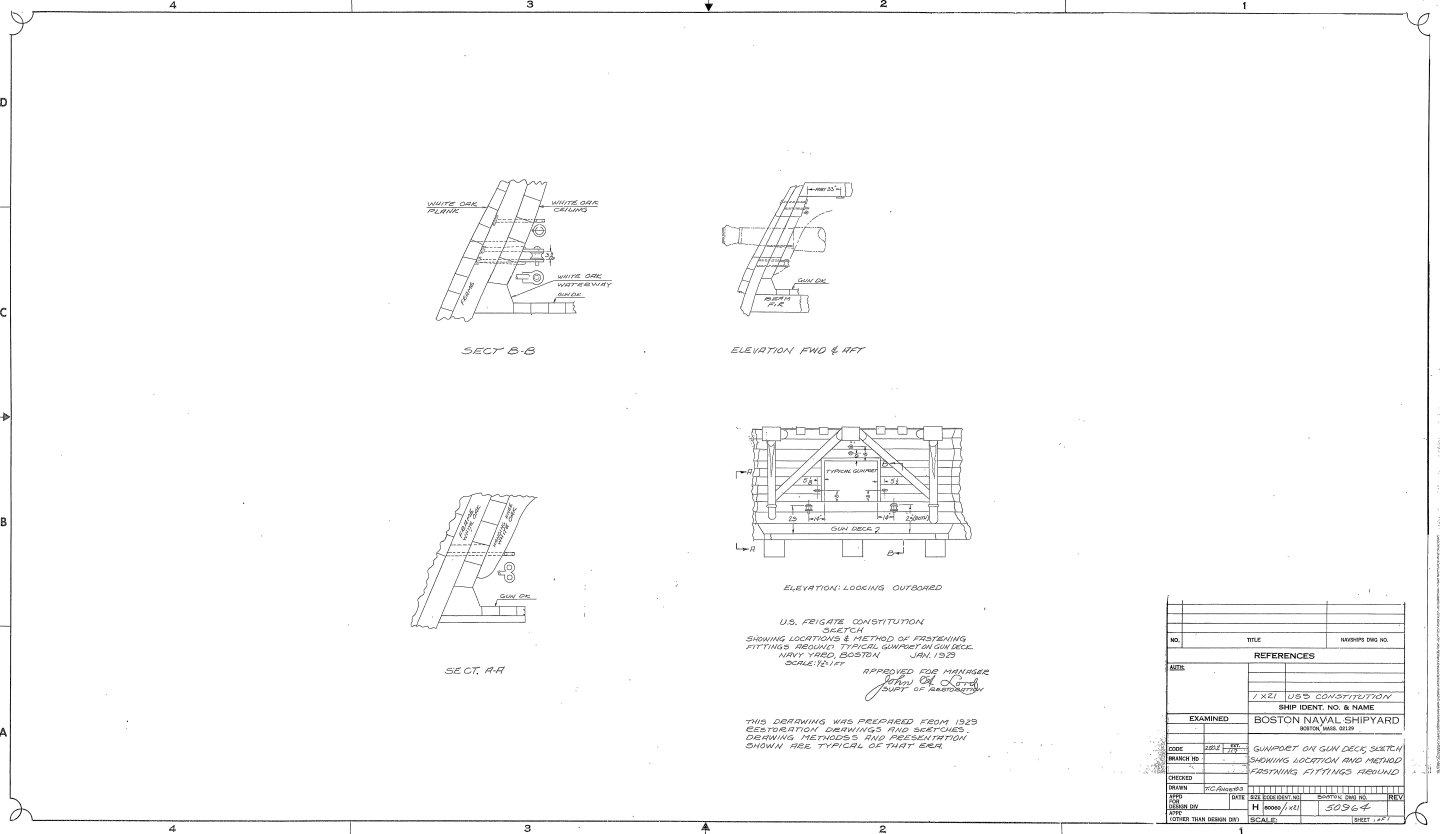
To fabricate the arched framework, I had to work out how to make the central ornament. If I had a metal lathe (and knew how to use it) it might have been relatively simple...I think, maybe. But I don’t, so this is how, why, and what I worked out, based on the US Navy plans.
-
Considering you said you had no experience with a lathe, was working with a piece of equipment you knew basically nothing about, and it broke, you managed to produce a gun barrel that looks spot on to your drawing as well as the one seen outside the buildings of Savannah College of Art and Design. Well done!!! Knowing nothing about casting, I look forward as to how you create a mold so that you can cast numerous copies of the barrel. Jon
-
I might even be worse for the MS kit! That's why we have forums, to share ideas and learn from each other. Jon
-
Unegawahya: I am making slow progress on my first canopy, working out the process (I've had a lot of false starts). My current method, so far, has worked out to be way more complicated than yours. I will post details and pictures once the fabrication and installation is done because I still don't know if what I have done up to now will be the final method. Jon
-
Ha! Trying to steal my thunder Gregg!!??😁Here is the plan for the wedge type carronade. And yes, Mr. Hunt used oversized eyebolts. Jon

-
You were smart. You didn't attempt install the hundreds if not thousands of pseudo bolt heads on the bulwarks at 1:96 scale. Robert Hunt's practicum used the rivets from Tichy Train Group for those boltheads which I thought were out of scale even on the 1:76.8 scale MS model. It's the reason I made mine smaller using a punch. However, it looks like plastic rivets were perfect for the larger eyebolt bolts showing on the hull. Well done. Your sheaves worked out nicely as well. Both the hull boltheads and sheaves will meld into the hull and hide when they are painted black. The reason why I don't mind this is because I want the viewers to see more detail the more they look, and the closer they look. The viewers should not get bored. Jon
-
As "easy" as it is to make eyebolts, it's the shear number of them that is required that makes it a pain to make. I make small parts like this on an as required basis, so I don't go nuts making very large quantitates. I bought a bag of one thousand 1/32" eyebolts on ebay from Model Expo some time ago that didn't last as long as I thought it would. It's amazing how useful those tiny items are for all sorts of things. Unfortunately for 1/96 scale builders, 1/32" eyebolts are still out of scale in many areas. Don't forget, you still need to blacken them as well, because paint will clog up the eyes. Jon
-
USS Constitution by mtbediz - 1:76
JSGerson replied to mtbediz's topic in - Build logs for subjects built 1751 - 1800
Great looking model! Jon -
Beautiful work! Jon
-
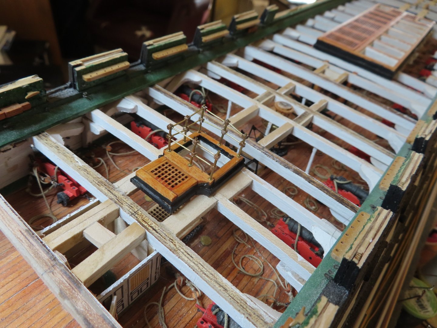
Peter, that's a thought (now Plan D), but I would like to include the frames if I could. It wasn't so much as to "keeping lines randomly scattered around the deck to show the ship in a state of action" but to show a working ship. There is a lot of stuff on the busy decks so they are not as neat and clean as many other models show. My ropes lines are loosely coiled because they are theoretically in use, not set up for formal inspection. Presently, I don't plan on adding sails (it's taking long enough as it is), so presumably this is what the ship would look like in dock for a while, in which case the canopy frames would be set up. But then again, they didn't exist during the ship's active fighting years. I'm working this out one step at a time. I'm still trying to figure out how to attach the multitude of arched brass rods together at the hub. I've been doing a lot of thought experiments as how to precisely hold in place 7 to 8 rods, plus a ringed ornament securely enough at the same time and with sufficient surface area to apply glue such that the assembly won't fall apart as soon as I try to move or install them into their positions on the stanchions. Mustafa, at the rate that I am moving, I suspect you will be working on these very soon. It should be very interesting if you method solves my problems. Jon
-
Peter, I inquired to helmarsowick as to how to get the 3D printed canopy supports for a potential Plan C should my attempt of constructing the supports fail. Plan B was substituting styrene for brass. Jon
-
I am building the Model Shipways' USS Constitution and saw one of your 3D printed canopy frames on Unegawahya's build log. You explained that you had a Polish friend print them for your model. I am attempting to make them myself out of brass rods, tubes, and styrene tubes, but I am progressing very slowly and don't know if I will succeed. As a possible Plan C (I already had problems drilling brass and had to go Plan B: substitute styrene for brass), would it be possible for you to connect me with your friend either through you as an intermediary or directly to me? Should I take that route, I have no idea what the cost would be. If it's reasonable, is something we can work out?
Thanks, Jon
-
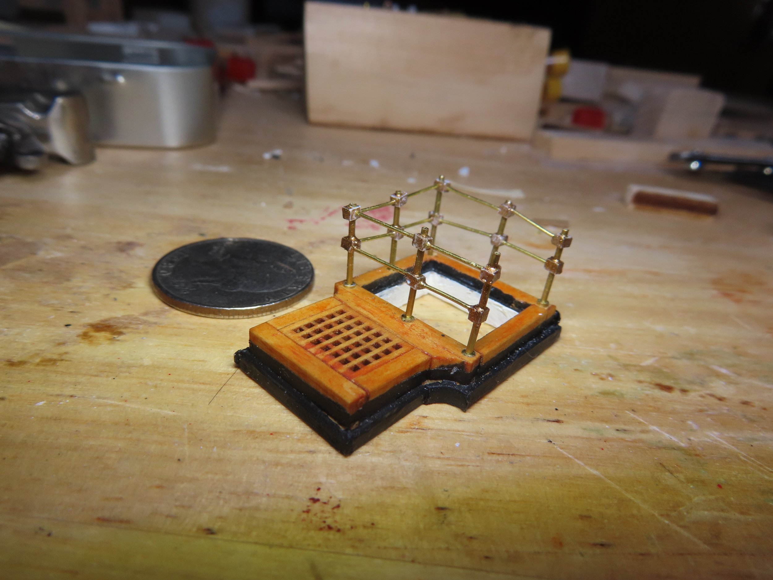
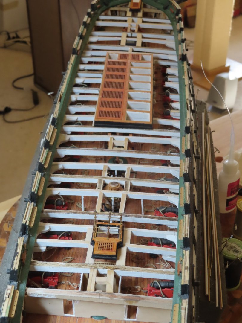
Per the USS Constitution Museum, the arched canopy frames were likely installed when the USS Constitution became a U.S. Naval Academy training ship in the 1850s, so they were not installed for tourist. They have been on the ship for about 175 years. That is why I am installing them; it’s officially part of the ship. Don’t be discouraged by my efforts, I am learning like most of us builders; trial and error (mostly error) is par for the course. Use me as an example as a "glutton for punishment," not as an excuse for not doing something because it is a challenge. If you feel intimidated, follow other builders who have had more success with drilling brass and used more robust brass rod (although out of scale). I've even seen images of 3D printed canopy frames, but can't remember where; so, there are alternatives methods. So here are the pictures you requested. Please be aware the frames are not complete yet and don't stand out visually yet because there is no planking to provide a smooth background. Jon


-
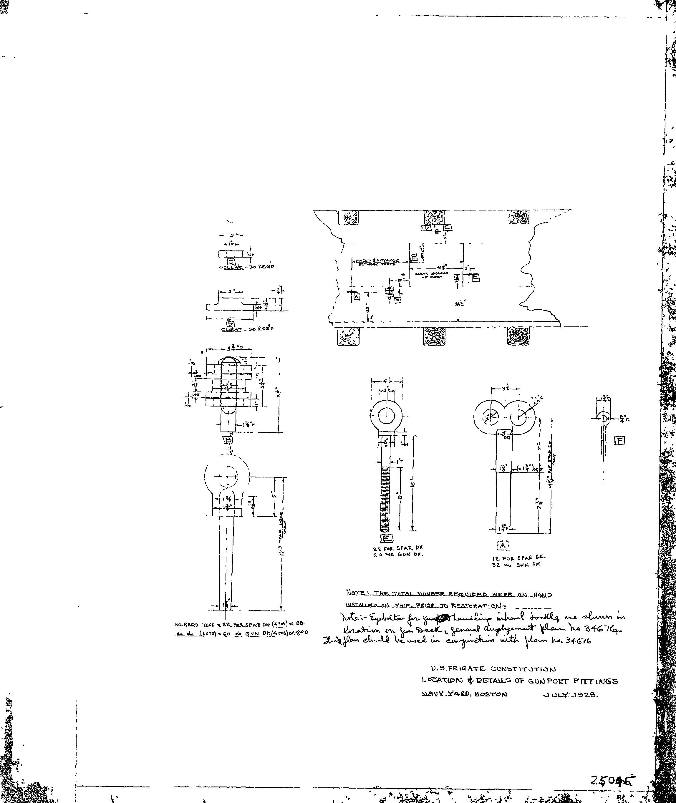
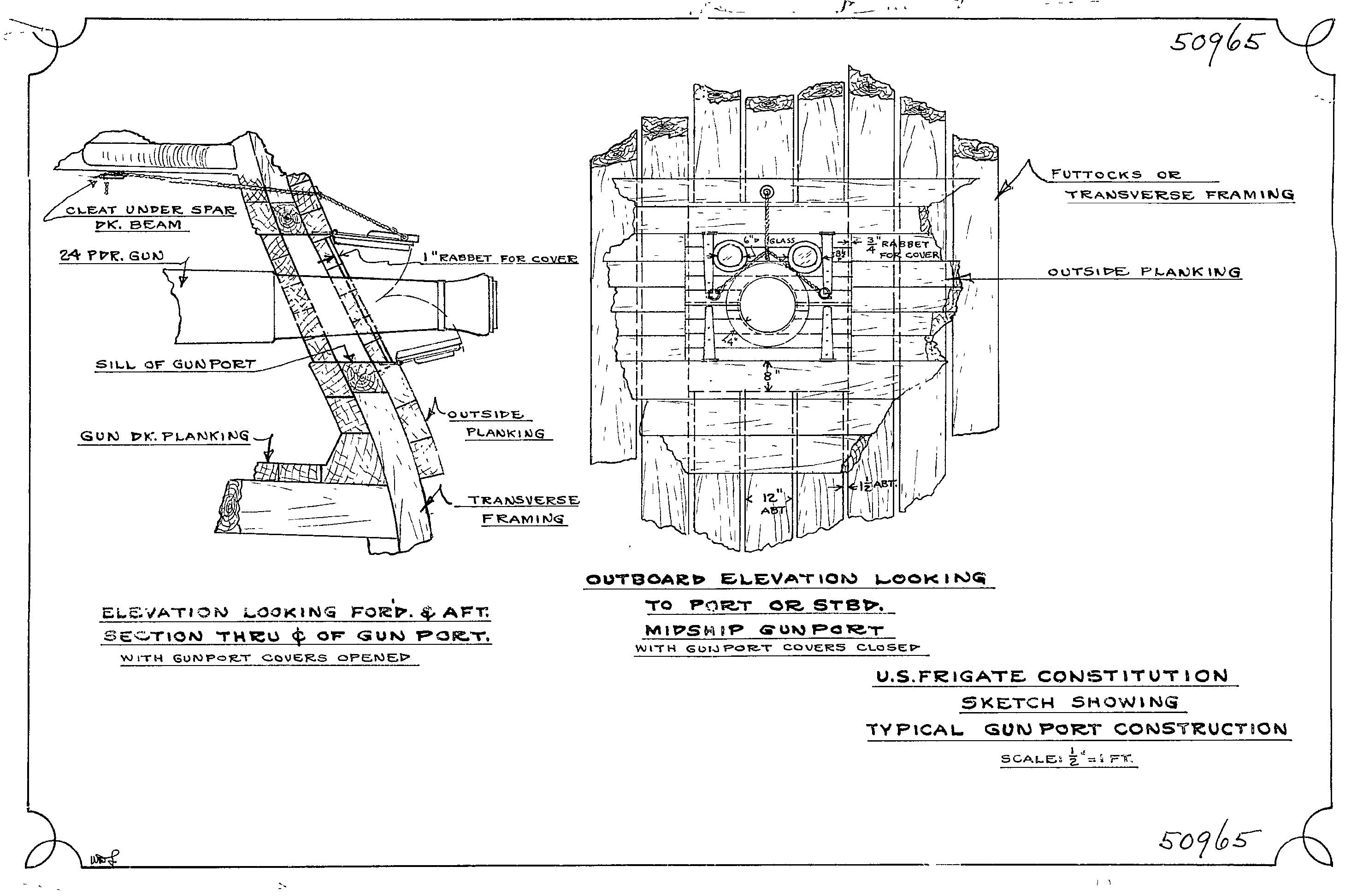
I have not found any commercially made eyebolts smaller than 1/32", but at my scale of 1:76.8, that was good enough for most of my applications. Anything smaller, might be a waste of time and effort at 1:96 as they won't be easily discernable. Also at 28 gauge, a few bends and the wire will probably break and getting thread through the eye will be a trick. We are close eyebolts/per gun in the count. I get the following per gun: 4 - recoil rope (2 required per side) 2 (or 1 double) - pull-in tackle 1 - pull back tackle 5 - gun truck 2 - gun truck rings OR you could do what many other builders have done - just install the recoil ropes for a simpler, cleaner look (read less eyebolts). I didn't because I am detail anal and wanted to create a more realistic mess. Here are some drawings that might help in general.


-
I had to work out the sequence of CA gluing a block to a rail and sliding the block and rail component down the stanchion to the bottom position and have the rail slip into the block on the other stanchion with precision. Then do it again for the top rail. Those rails lengths had to be precise which meant nipping the ends of the rail and filing to shorten the brass rod within thousands of an inch by trial and error. Then gluing the rail into the block so it didn’t protrude into the stanchion’s vertical hole, about 1/64”. Invariably, I broke glue joints, crushed blocks, lost the tiny pieces if I dropped them, and had to refabricate numerous parts Now I must bring 7 arched 1/32” brass rods together into a styrene ring that is to hold them together at the center of the stairwell and add a yet to be fabricated ornament it its center. So, this is as far as I got in all this time.