JSGerson
-
Posts
2,649 -
Joined
-
Last visited
Content Type
Profiles
Forums
Gallery
Events
Everything posted by JSGerson
-
 Because I chose the 4 3/4" sized boat to fit the Rattlesnake, I'm treating my model boat as 1:64 scale, the same as the Mamoli kit. I thought about a bow locker, but not sure what it would look like for this boat. Take a look at the boats Captain Steve made for his 1:76 scale USS Constitution. He did a fabulous job on four different boats. There should be plenty of ideas to choose from for lockers, seats, oars, etc. Jon Edit: changed "six" to "four: I stand corrected
- 55 replies
-
- 2
-

-
- ships boat
- model shipways
- (and 1 more)
-
It's coming along very nicely. You're making a lot more progress than I am as I plod along. I did notice that you ended up with the result that I have been trying to avoid so it will be interesting to see how you handle it. There is a gap between the bow bulkhead and the planking which I believe is a model design flaw. As I figured it, there should have been a notch in the keel for the bulkhead and handled just like the ribs. It would have made the bulkhead wider so all the planking would have fitted flush. Hopefully, when all the other stuff is put it their place, this minor flaw will be hidden. Jon
- 55 replies
-
- 1
-
-
- ships boat
- model shipways
- (and 1 more)
-
If you don't mind, I've got a few more question for you: Did you notice that the transom seemed to be short in height? On my model there was a 1/16" of an inch gap inside the the keel transom notch. At first I thought the gap must have a purpose that would reveal itself as the build progressed, but now I don't think so. I added a filler strip across the transom. Since you are ahead of me, did you run into the same thing? Did you have trouble determining where the sheer strip actual met the stem? It appears to be above where the curved 1/16" strip ends on the stem. I guessing the point of contact to the stem is forward of the curved stem strip because the planking would be against the strip. The plan is not very detailed there. What did you do? Thanks, Jon
-
Painting is not an option I'm considering at this point as the boat will be on board my unpainted Rattlesnake. The only deviation from the natural wood color on the ship is the black trim. I didn't have ebony wood so the black is painted. I'm like you, I'll see how the basswood looks and if I have to, I'll stain the wood. I'm looking forward to your next progress report. Jon
-
Cute! Since you started over and had to make a new keel and jig, are you using the original kit basswood for the planking? Are you planning on paint or stain the wood?
-
It looks like your patience is paying off. She's really starting to take shape. I just hope I do as well as you. I just have to ask, what is with the coins? Are they there to indicate scale or port from starboard or both?
-
Alright, another ship's boat builder! I took a look at your log and your are doing great especially for a "first timer." So far it seems that you and I have had our problems with bending the ribs. Since you are ahead of me, Keven, I now have someone to follow. Out of curiosity, what size kit are you building?
-
There seems to be a lot of anticipation as to how this build will turn out. I hope I don't disappoint.
-
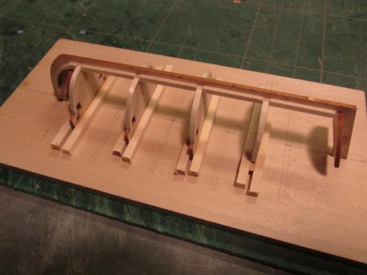
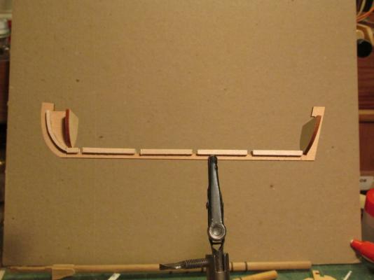
The image below shows the dry fit of the assembled jig. Once it’s glued into place, the real building of the ship’s boat will begin.
- 93 replies
-
- 1
-
-
- ships boat
- model shipways
- (and 1 more)
-
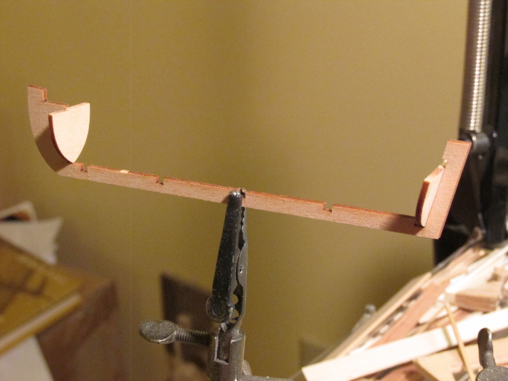
Eight 1/8” were cut about 2” long and glued to both sides of jig bottoms.
-
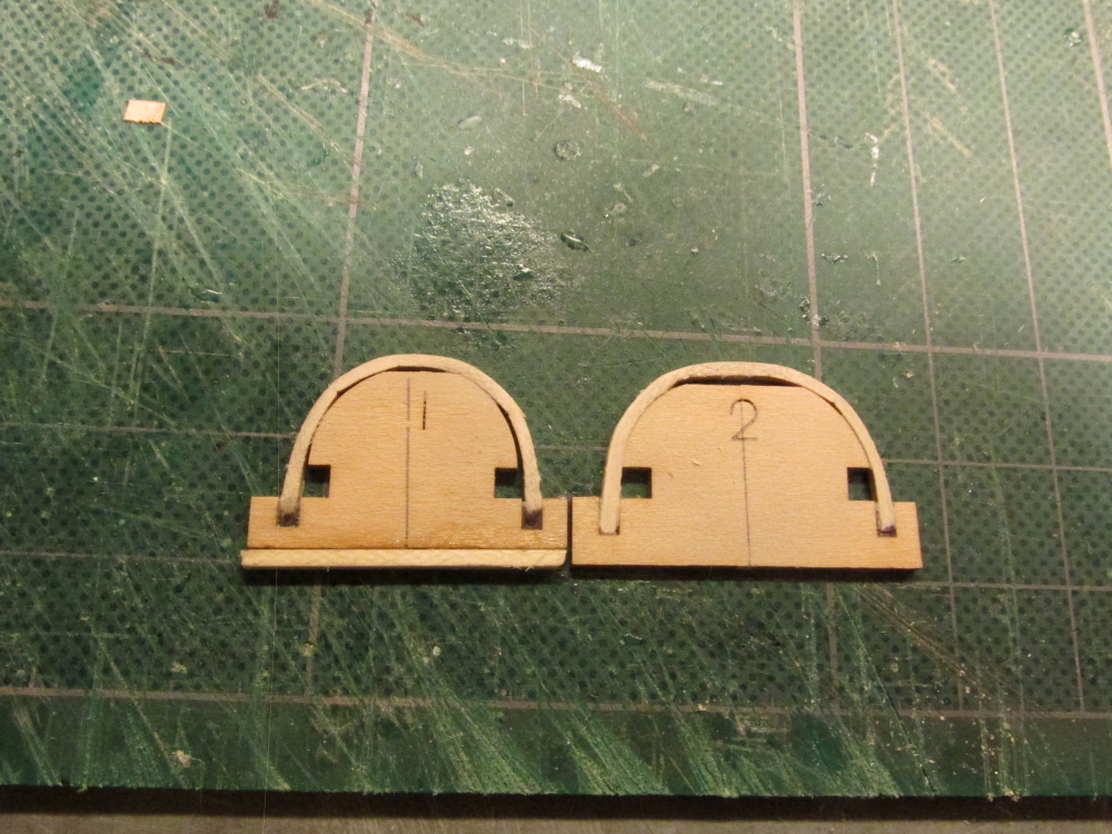
During a dry fit I noticed that jig No. 1 seemed to be short in height by about 1/16”. This was remedied by adding a strip at the bottom.

-
The cardboard "trick" might work but if I were to do it again, I might try using thinner strips and laminating them. First it would make bending easier and second the resulting rib would be stronger. Live and learn.
-
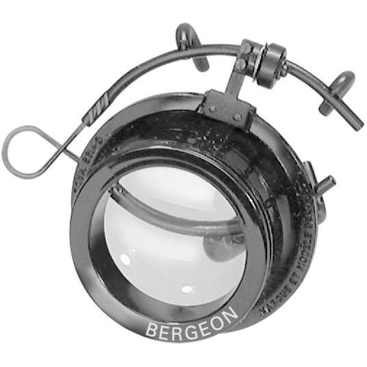
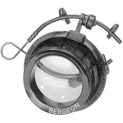
I'm blind as a bat having to wear strong magnifying glasses since I was seven. I've been wearing tri-focal lens for years now and even then I still need a magnifying lens to read fine print. I use a clip-on 3 Doppler Ary eye loupe to do my model work. It clips on and it flips up and down as necessary with ease. The one I have, I bought many years ago, probable in the late 70's and it still works fine. Today, they go for about $80 odd today. I have no idea what I paid for mine.
-
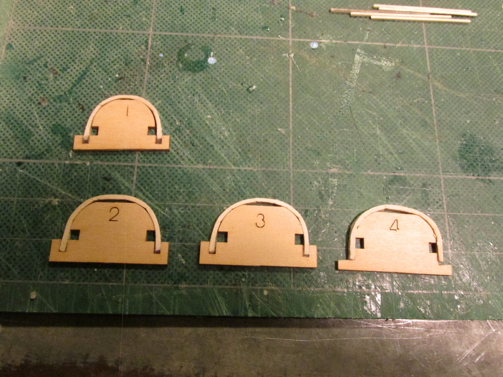
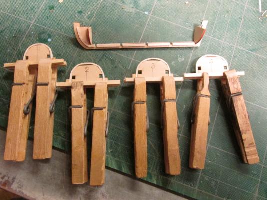
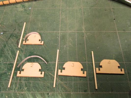
Bending the ribs was easier said than done, at least for me. My method to bend the wood was to use the heated iron. But because the bend is 180° the wood wants to kink or worse split. I also tried using my clamp type wood bender which put little creases on the inside of the bend; that was a disaster. I finally got some satisfactory (not great) results working very slow with the heated iron and repeated dippings in water, but I used a lot of time and wasted more wood than I think the kit allows. Another part of the problem was how the strip of wood was held in place on the jig. It can’t take much stress due to the 1/16” thinness of the jig and the softness of its wood. If you don’t bend the rib wood strip enough prior to putting on the rib jig, forcing the strip into its final shape on the jig will break the jig. You can see that result in jig No. 4. All the ribs ends are glued to the jig at the bottom. Hopefully the flaws will be buried under planking and internal boat structures. BTY, the gap at the top of the arch is supposed to be there to make it easier to remove the hull from the jig.

- 93 replies
-
- 1
-
-
- ships boat
- model shipways
- (and 1 more)
-
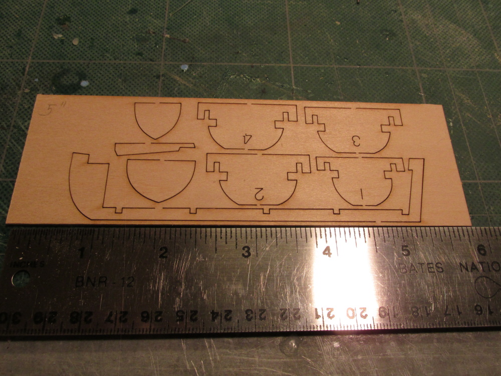
The Main Ribs The kit provides 4 rib jigs to form the main ribs. Nos. 2 – 4 are the same size. Using the “paper” method, 4 pieces of 1/16” square stock were cut to length. The idea is to soak the strips and then bend them around jig form and glue them, just at the ends, to the jig. I soaked the wood for 24 hours. At a later point in the build, the ribs are to be cut from the jig.
- 93 replies
-
- 4
-
-
- ships boat
- model shipways
- (and 1 more)
-
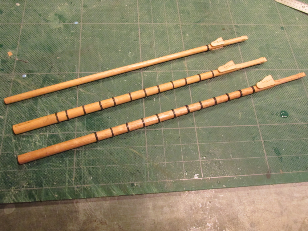
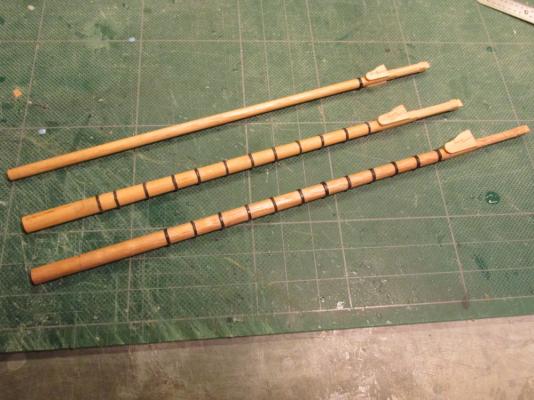
Masts…Again Meanwhile, back at the masts, all three lower masts were completed to this point:
- 974 replies
-
- 2
-
-
- rattlesnake
- mamoli
- (and 1 more)
-
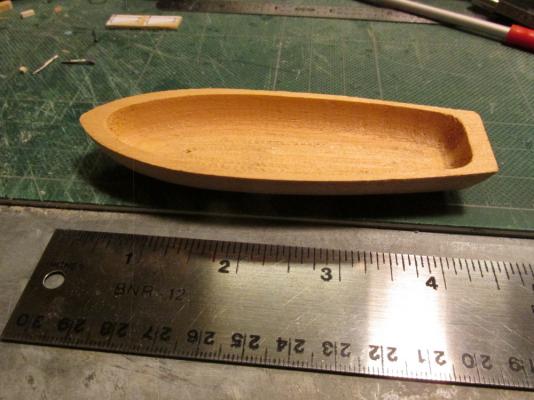
The boat shell (without rudder) that came with the Mamoli kit is about 4 3/8" (see photo), and the Model Shipways' boat that you construct "bread & butter" style is just shy of 5". I purchased the 4 3/4" kit because the next size up was 5 3/16". All of the boat are similar but not quite. So who is to say with certainty which one the actual ship had. If I really screw it up, I can always fall back to the kit's boat (I hope not).
- 93 replies
-
- 1
-
-
- ships boat
- model shipways
- (and 1 more)
-
I'm curious to see how this turns out too!
-
Ship’s Boat Due to a number of everyday life interruptions that we all endure, the mast construction proceeds but at a slow pace. At the same time I have begun the construction of the ship’s boat. And here I have taken a complete deviation from the kit and the Practicum. Instead of using the wooden shell provided by the kit, I decided to build a POF ship’s boat using Model Shipways kit No. MS0108 and made a separate log here.
-
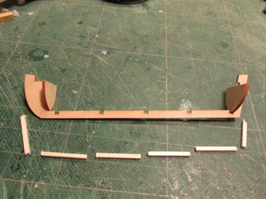
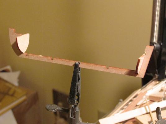
After the strips were dry, they were cut to their final size and glued into place.
- 93 replies
-
- 2
-
-
- ships boat
- model shipways
- (and 1 more)
-
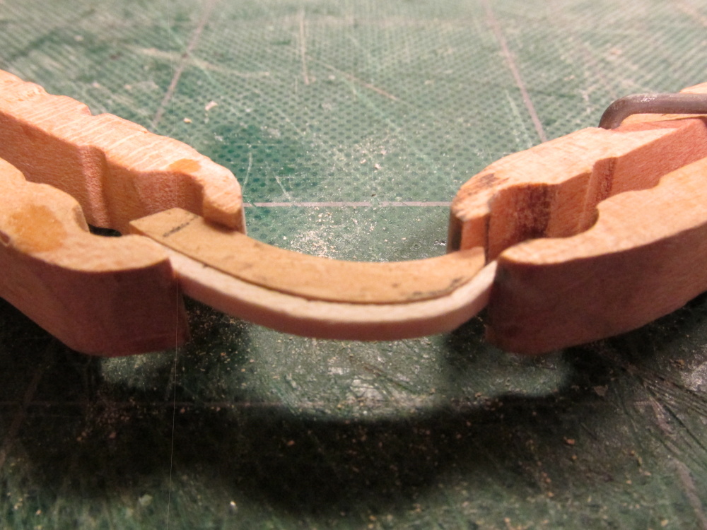
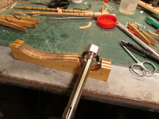
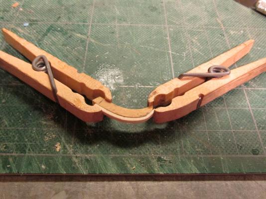
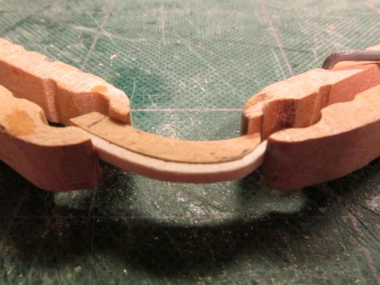
The length of the bow strip was measured by using a strip of paper. Placing the paper in the position where the curved wood strip would have to go it was cut to size. Then the paper was flatten out which provided a direct measurement of the length of wood needed. After cutting the wooden strips to length, they were soaked for at least an hour. Using a heated plank bender, the strips were bent into the approximate shape and placed on a simple wooden form made in the final shape for the occasion.
- 93 replies
-
- 2
-
-
- ships boat
- model shipways
- (and 1 more)
-
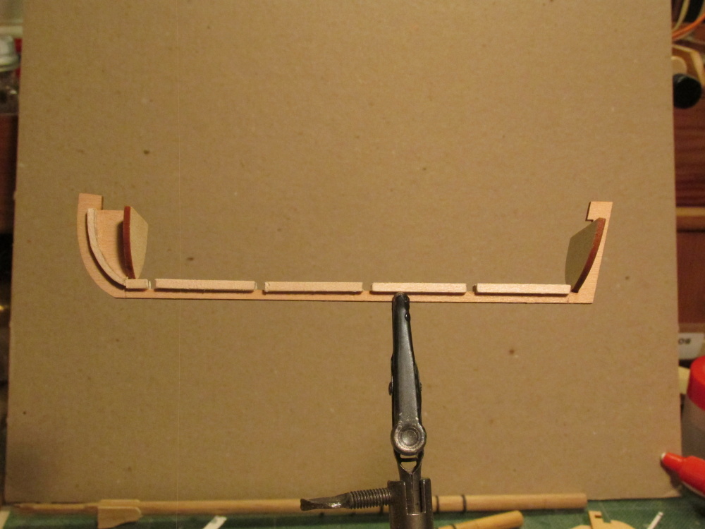
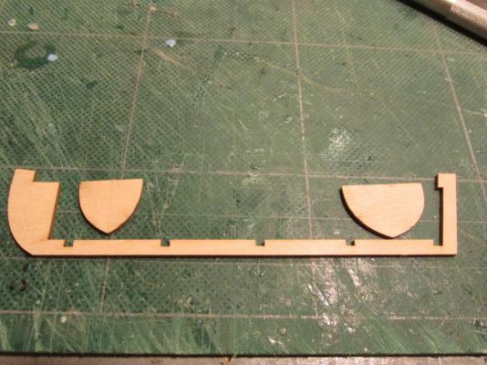
1/16” square strip stock was then glued to both sides of the keel between the rib notches, flush with the top of the keel. The notches are where the ribs are to be installed later. Because the strips must also curve up the bow, they had to be pre-curved.
- 93 replies
-
- 3
-
-
- ships boat
- model shipways
- (and 1 more)
-
Assembling the Keel The single piece laser cut keel is combined with the stem and the stern post. The bow bulkhead and the transom were glued to keel.

- 93 replies
-
- 2
-
-
- ships boat
- model shipways
- (and 1 more)
-
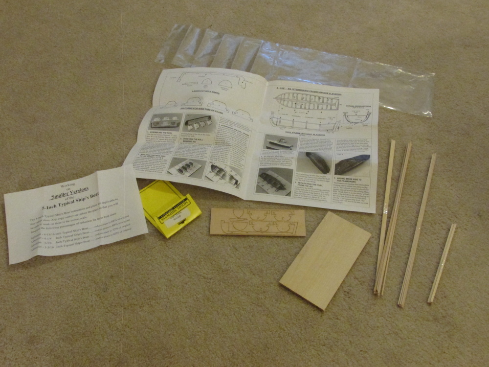
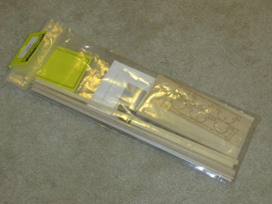
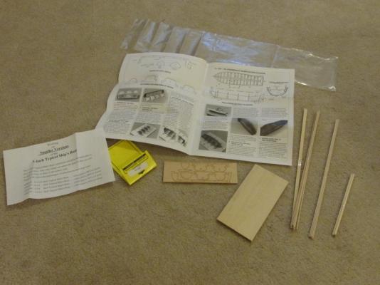
Model Shipways Typical Ship’s Boat* (SMALL) *As labelled on the kit. On the website it’s called: Plank-on-Frame Lifeboat Kit I am building the Mamoli 1:64 scale 1781 American Privateer Rattlesnake with the help of Robert Hunt’s Practicum. In the process of building the Rattlesnake, I had to make the ship’s boat. The Mamoli kit provided the model builder with a pre-cut wooden shell for the hull from which the builder could then create a completed model (which the Practicum addresses). If I had built the Model Shipways’ version of the Rattlesnake, I would have had to make the ship’s boat “bread and butter” style. Somehow neither option satisfied me. So I decided to go all out and build a ship’s boat from the keel up or as the case turn out, from the keel down. Model Shipways makes 5 sizes of kits; I purchased the Typical Ship Boat No. MS0108, a Plank-on-Frame construction kit (POF). Model No.: Size MS0105 3-3/16'' (81mm) MS0106 3-3/4'' (95mm) MS0107 4-1/4'' (108mm) MS0108 4-3/4'' (122mm) MS0109 5-3/16'' (135mm) This is my first POF as well as my first small boat build, so this will be all new territory for me. Not only that, I won’t have the Practicum to hold my hand until the hull is built. The kit is fairly simple, one laser cut sheet provided the keel, the bow bulkhead, the transom, and the frames to create the bot’s ribs. A bunch of stock wood pieces which I believe to be Basswood as it is fairly soft was also included. The instructions are straight forward but not overly detailed so a lot of the skills and nuances of model building must be brought with the builder. Unfortunately the resolution of the photo images in the instructions is low and therefore hard to see detail.
- 93 replies
-
- 3
-
-
- ships boat
- model shipways
- (and 1 more)
-
I saw the woolding's in Lee's The Masting and Rigging of English Ships of War 1625 - 1860 and then I looked at Hahn's plans. They didn't look like wooldings in the plans. Maybe American ships were more progressive than English ships in 1781, I'm no expert. I did think about using the wooldings, but the Hahn's plans showed rings, so I put in rings. As for the lathe, I'm a total newbie. I really don't know what I'm doing and am learning by trial and error...mostly error.