JSGerson
-
Posts
2,649 -
Joined
-
Last visited
Content Type
Profiles
Forums
Gallery
Events
Everything posted by JSGerson
-
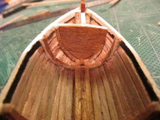
 Using the Teak planking I made for the hull, a new bulkhead was veneered over the original. The same was done to the transom to match.
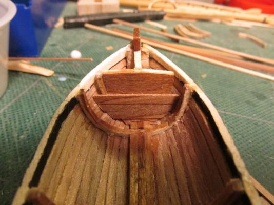
- 93 replies
-
- 2
-

-
- ships boat
- model shipways
- (and 1 more)
-
You will notice that the pre-cut bow bulkhead was too small and I had to beef it up during planking so it was not a pretty sight.
- 93 replies
-
- 1
-
-
- ships boat
- model shipways
- (and 1 more)
-
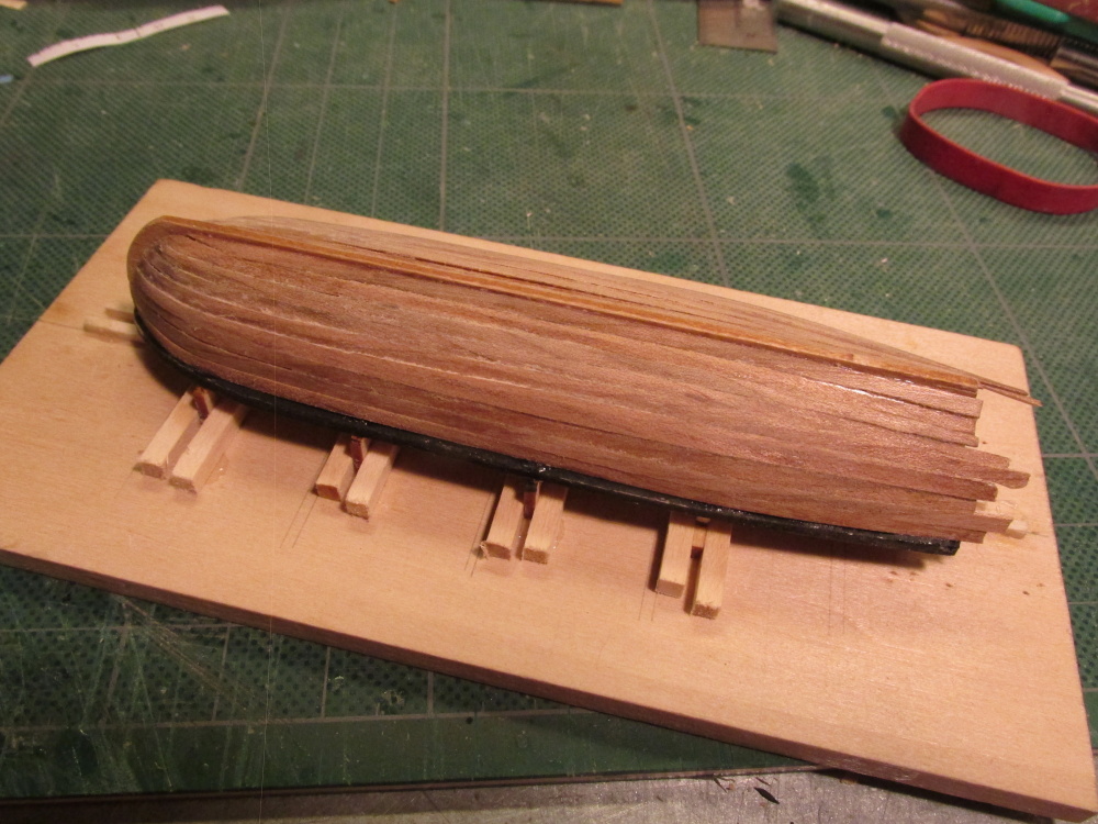
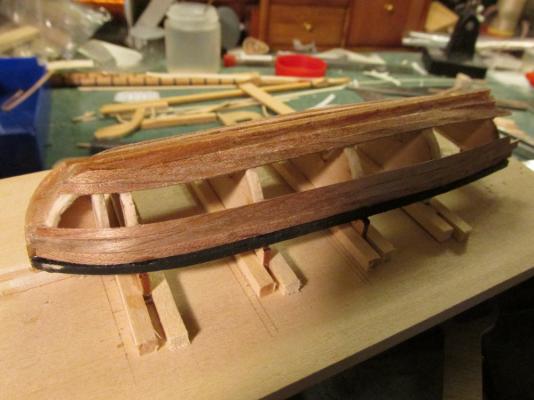
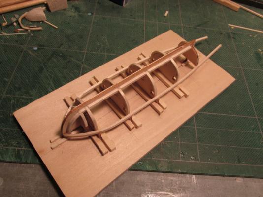
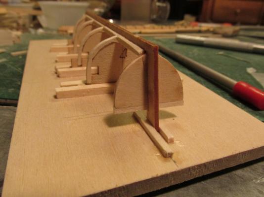
The excess planking was removed at the stern, but in the process the unsupported stem post above the hull broke off. That was because the grain of the wood was horizontal so it had no strength. A sneeze could have knocked it off so it wasn’t unexpected. If the stem post had been constructed like a real boat, the grain would have been vertical but because this was a very cheap kit (I paid $5.00 on sale, otherwise $8.00) a lot of detail was spared. I will address this later. The light colored basswood ribs and keel looked like tan lines against the darker Teak so I stained them with Early American 230 Minwax Wood Finish (what else?) to match the Teak.

- 93 replies
-
- 1
-
-
- ships boat
- model shipways
- (and 1 more)
-
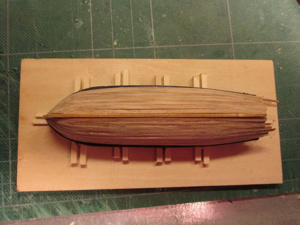
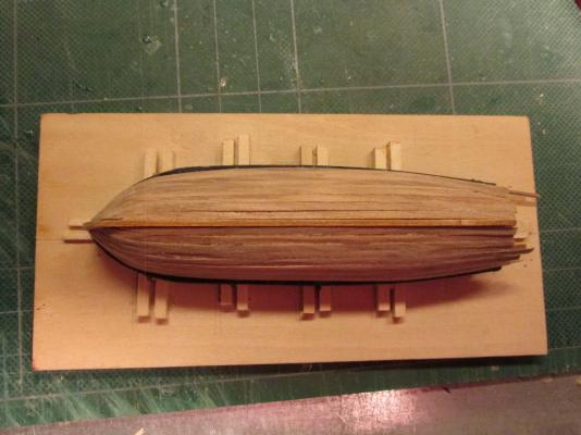
Spud1 - There was no real problem removing the hull from the jig. The only thing holding it down were the ribs which extended into and were glued to the jig. Since they were basswood, they were easy to cut. There was one causality, the rudder post. Because the keel included both the stem and the rudder post, the grain of the wood ran horizontal at these points. Because of this, all one had to do was was breath on the rubber post and it would snap off, which it did. I will discuss all of this in my next post.
- 93 replies
-
- 1
-
-
- ships boat
- model shipways
- (and 1 more)
-
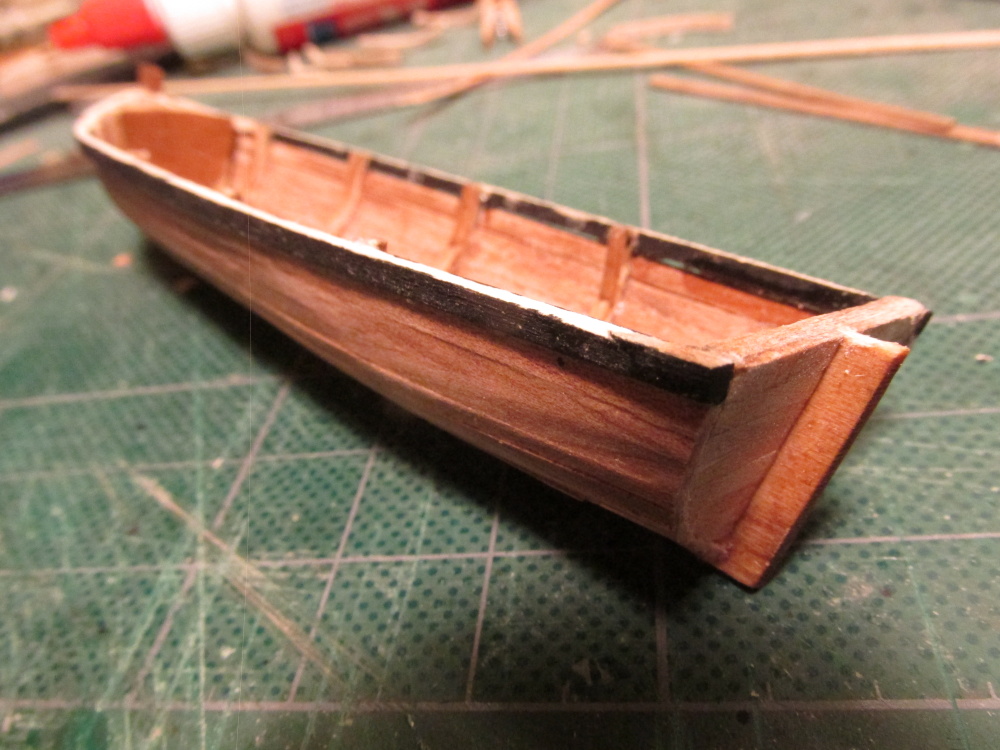
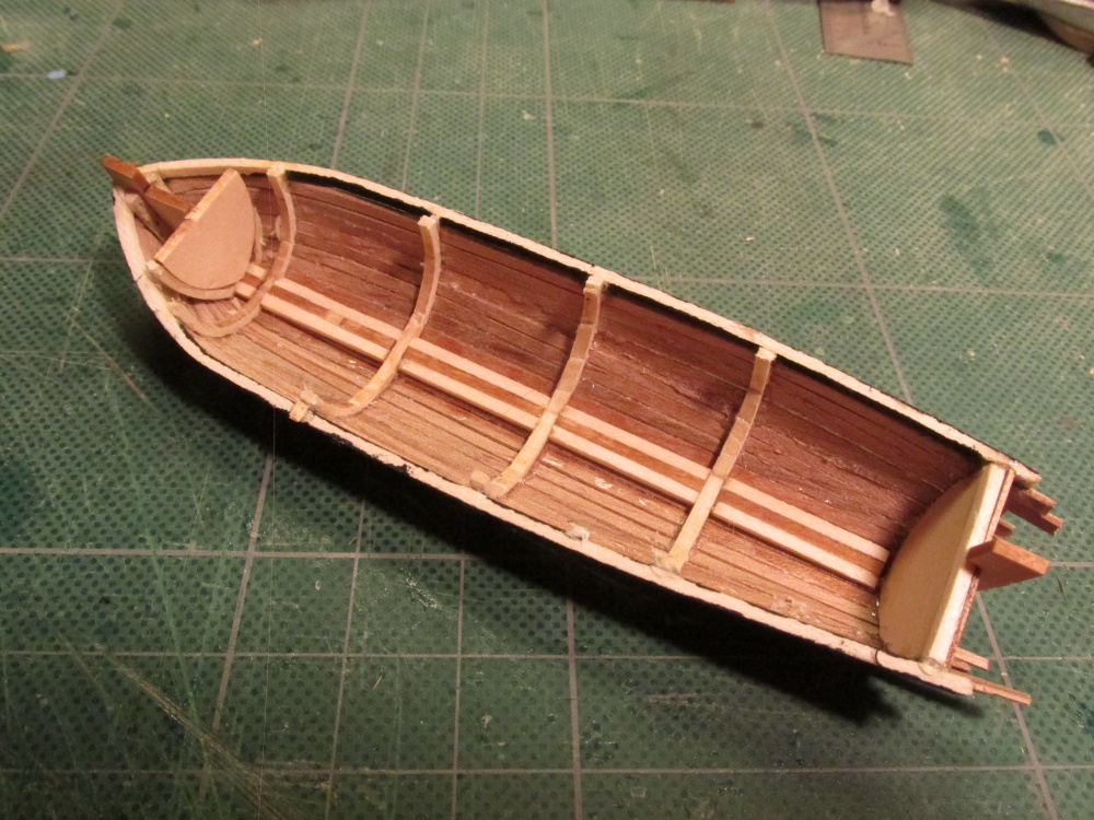
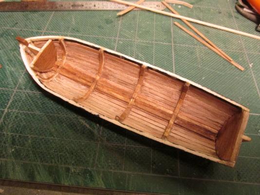
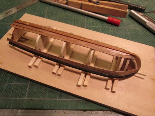
These final shots of the boat show the raw planking complete. The last shot, the boat has been removed from the building jig. The outside has had a preliminary sanding. The planks still hang over the stern and the interior desperately needs to have excess glue removed and sanded. No treatment to the wood surface has been applied yet.


- 93 replies
-
- 8
-
-
- ships boat
- model shipways
- (and 1 more)
-
It’s been a while since my last post, but progress has been made. Slowly I applied the planks, removed them and applied them again trying to keep the fine gaps between the planks at a minimum. Due to their thinness, the planks have a tendency to bow between the ribs. It would have been a lot easier to plank had there been more ribs.
- 93 replies
-
- 2
-
-
- ships boat
- model shipways
- (and 1 more)
-
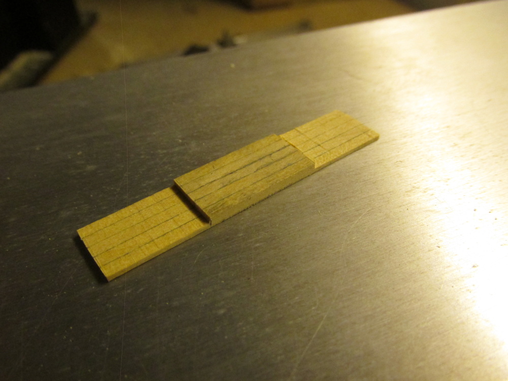
The result was a strong 1/16” x 1/16” strip in perfect shape. After a little sanding and trimming, it was glued into place.
- 974 replies
-
- 4
-
-
- rattlesnake
- mamoli
- (and 1 more)
-
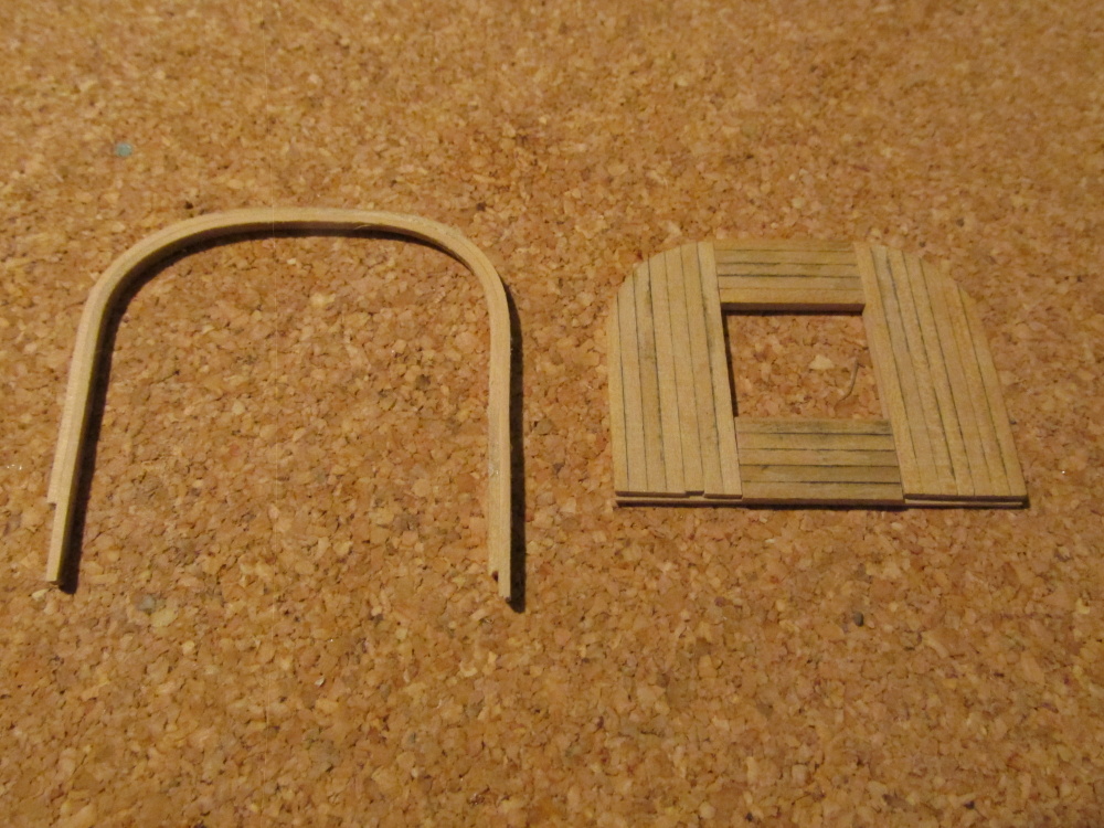
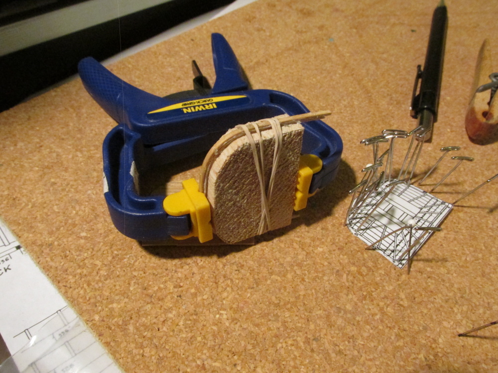
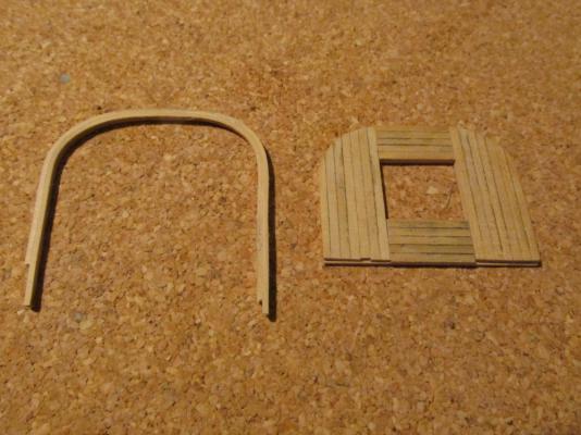
Grabbing a “spare” piece of boxwood stock (if I run out later, I’ll buy some more), I milled 1/16” x 1/32”strips, half the thickness called for. After a half hour these were ready and pliable. Instead of the pins, using some balsawood, I made a form in the shape of the platform. I laminated two strip pieces together with WeldBond and wrapped them around the form This glue gave me plenty of time to set it up and clamp before the it dried.

- 974 replies
-
- 2
-
-
- rattlesnake
- mamoli
- (and 1 more)
-
NOTE: For those faithfully following this log, I apologize for going at a snail’s pace. Each step for me is new territory and although I try not to make too many mistakes, it seems to me that although I may not repeat too many of them, it seems to me that I have made every one of them at least once. So bear with me as I plod along; there is no rush. Using the Hahn’s platform drawing as a template, the curve of the platform was traced onto the platform construction and the excess was then trimmed off. I used a disc sander. The platforms have a perimeter strip which is made in two parts. The back piece is simply a 1/16” square strip glued to the edge. The remainder is one long strip that is bent to shape. Mr. Hunt stated in the Practicum that he soaked his piece for 30 minutes to get it pliable enough to bend and glue, bend and glue in place using CA glue. I don’t know what kind of magic he was casting but that didn’t work for me. Initially I tried soaking the boxwood strip 2 days and then wrapping it around pins following the template I made earlier. As careful as I was, using both the heating iron method and a plank bending tool that make fine creases on the inside of the bend, the strip broke in two places due to the tight curve. I had the same problem when I was making the ribs for the ship’s boat. If there is some technique that makes this work, I don’t know what it is. It was time to be innovative.
- 974 replies
-
- 1
-
-
- rattlesnake
- mamoli
- (and 1 more)
-
I always looked forward to your next installment of your log. It's a shame (for me) that it has come to an end. Good luck on your next project.
- 104 replies
-
- 1
-
-
- rattlesnake
- mamoli
- (and 1 more)
-
The two planks next to the sheer rails were reinstalled. Additionally I installed the garboard planks and the planks next to it but not until I did that twice. It’s not perfect, but it’ll do. All of this was going on while I had my problems with the Rattlesnake’s mast tops (see log). Boy, was I having fun!
- 93 replies
-
- 4
-
-
- ships boat
- model shipways
- (and 1 more)
-
I didn’t like the way the basswood sheer rails looked next to the teak planks so I decided to add an accent to the boat to complement the mother ship Rattlesnake by painting them black.
- 93 replies
-
- 3
-
-
- ships boat
- model shipways
- (and 1 more)
-
Using the proportion method of planking I laid out the planking marks and added two planks to each side next to the rail on each side and ripped them out. I didn't like the way they looked.

- 93 replies
-
- 2
-
-
- ships boat
- model shipways
- (and 1 more)
-
Between now and my last post a lot has happened and I have really nothing to show for it. After the sheer rails were glued in place, I ripped them out because I found gaps between the ribs and the rail; which you can’t see in the pictures. Not good; I did it over.

- 93 replies
-
- 1
-
-
- ships boat
- model shipways
- (and 1 more)
-
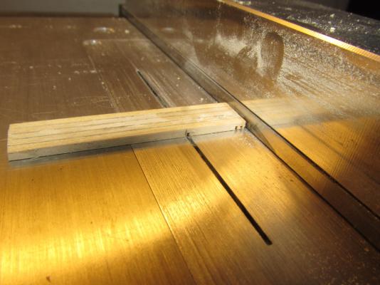
Once the glue was set (I waited 24hrs just to be sure), I fired up the Byrnes saw, and stroke by stroke, I nibbled away the wood to create the rabbet. Based on the dry fit, it worked like a charm.

- 974 replies
-
- 3
-
-
- rattlesnake
- mamoli
- (and 1 more)
-
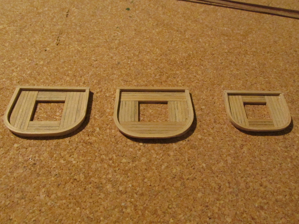
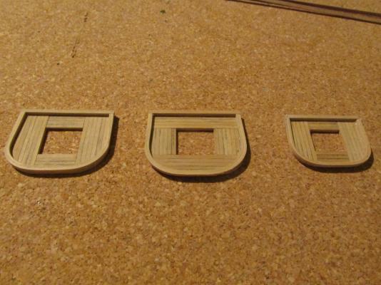
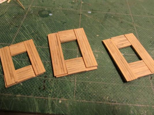
I am pleased to announce “success” is creating the platform pieces. All I did was change a few minor details: · I inadvertently used the “wrong” wood (Boxwood instead of prescribed Holly) · I switched from CA glue to Weld Bond · Changed from 1/32” square stock to 1/16” square stock

- 974 replies
-
- 2
-
-
- rattlesnake
- mamoli
- (and 1 more)
-
I'm not going to let those platforms get me. I am tenacious enough that I am giving the mast tops another shot using 1/16" square stock this time using wood glue instead of CA due to the larger surface area. So intent was I that after I chopped up some 1/16 x 1/16" wood to size and glued it together, I realized that I grabbed boxwood instead of holly as called for in the Practicum. I just can't win for losing. Well, so be it; boxwood it is. Martin - Both the Practicum and Model Shipways are following Hahn's plans for the tops. Mamoli shows planking as well, just that all the planks are in one direction. I'm not giving up on the Practicum just yet. It's gotten me this far which I would never been able to do without it. I'll just have to be more careful with these later chapters as they have more errors and omissions due to his rushing and corner cutting in the late stages of building his model and writing the Practicum. He indicated somewhere that he was building 4 models and writing their practicums all at the same time while trying to meet some deadline. It shows. Boy are we having fun now.
- 974 replies
-
- 2
-
-
- rattlesnake
- mamoli
- (and 1 more)
-
It’s been a while since my last post and I had hoped to say I made some progress, Alas, this is not so. I am back to square one not once but twice in trying to construct these platforms. After I tried numerous times to create the platforms using the 1/32” strips and then have them fall apart as I attempted to create the rabbet, I decided to bite the bullet and cheat. I would create the platforms using 1/32” boxwood sheets. Then I planned on scribing lines on them to make it look like they were made of strips. I meticulously measured and milled the boxwood from a thicker piece of stock and then cut them to size exactly as indicated in the practicum. Everything went according to plan until I laid them out before I attempted to cut the rabbet. Something did not look right. The dimensions were correct except the pieces looked too narrow. Placing the pieces on Hahn’s drawing of the mast tops I discovered the problem. The Practicum lied. The strips should have been 1/16” x 1/16” NOT 1/32” x 1/32” as indicated. The lengths were correct but not the widths. Therefore, I will have to start over again for a third time.
-
Very nice. I'm still plodding along, one step forward then two steps back. I'm no further ahead than I was 3 weeks ago. I must commend you for a job well done.
- 55 replies
-
- 1
-
-
- ships boat
- model shipways
- (and 1 more)
-
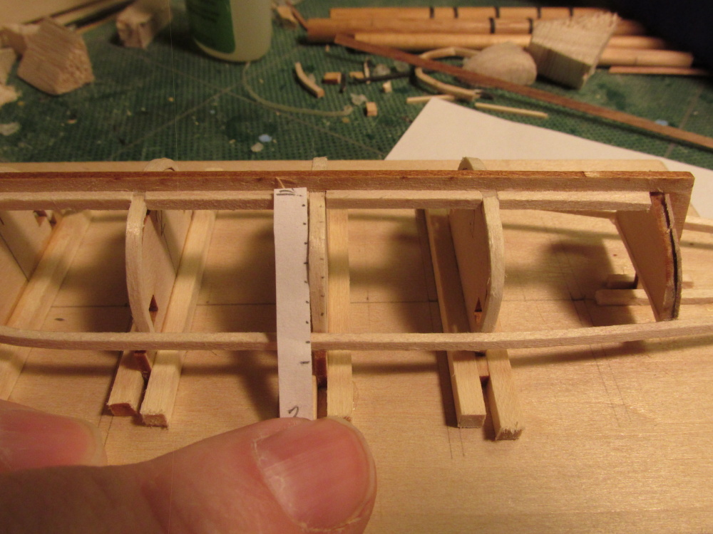
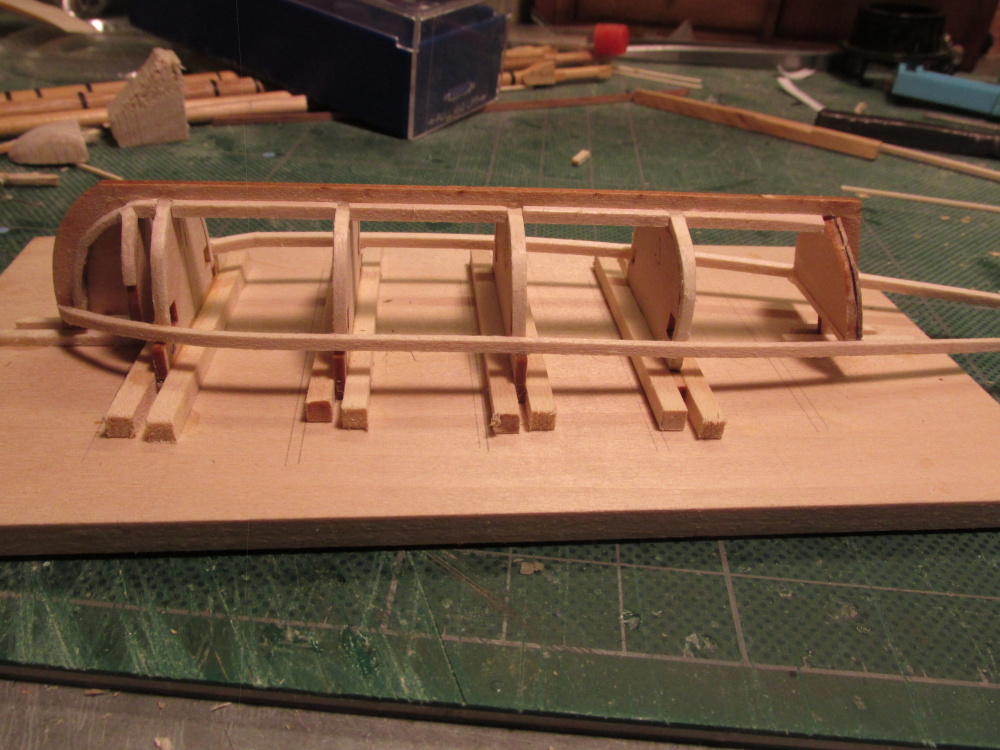
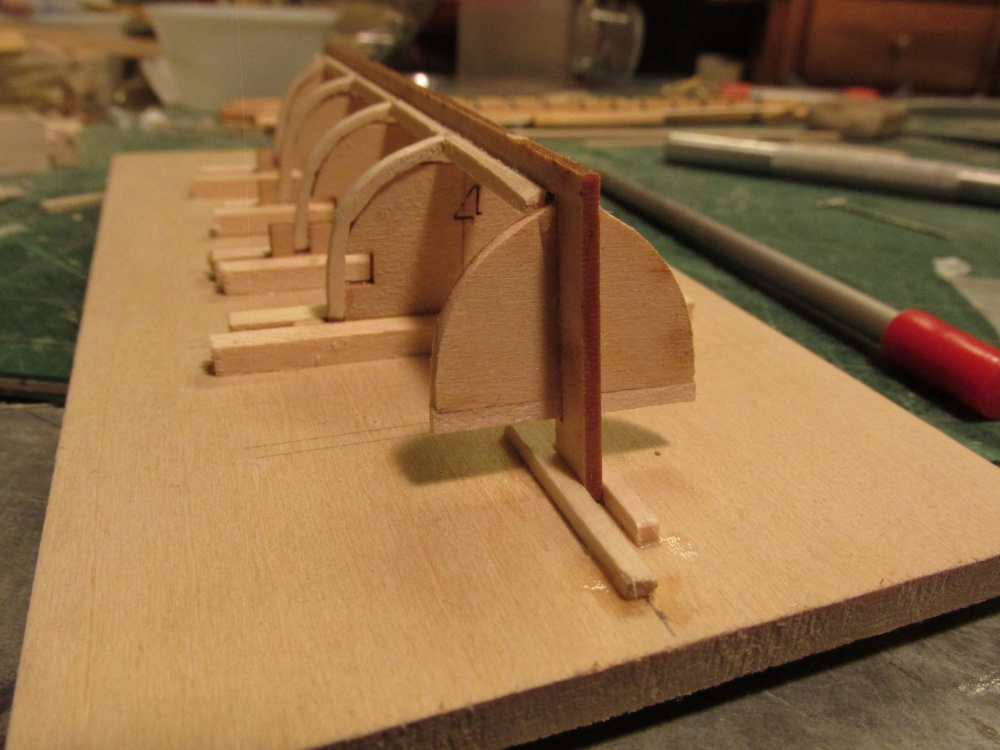
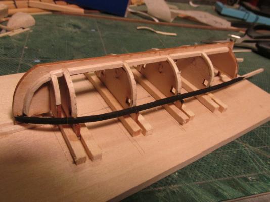
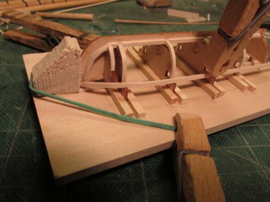
Once the wood was bent and dry, it was dry fitted. Here it was discovered that again, either the instructions were not clear or the parts did not match the plans. All of the ribs had notches in the keel, the stem bulkhead did not. This created a disconnect as to how the planking would flow over it. The bulkhead also seemed too narrow so I tried to beef it up by adding more basswood. Even then it appears that I will have to use some wood filler to fill in some of the open gaps. The first sheer line was glued in place with WeldBond at the bow. It will be completed when it is glued to all the remaining ribs and the transom. Of course this will be repeated for the other side.
- 93 replies
-
- 2
-
-
- ships boat
- model shipways
- (and 1 more)
-
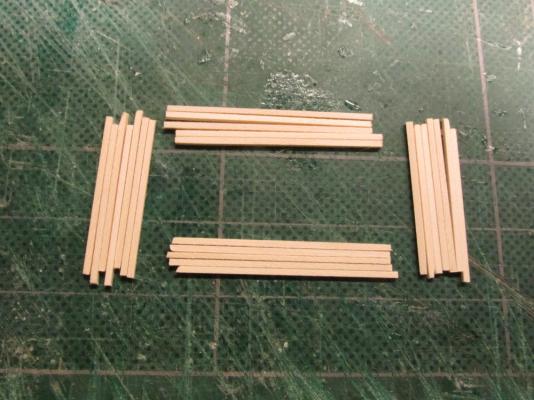
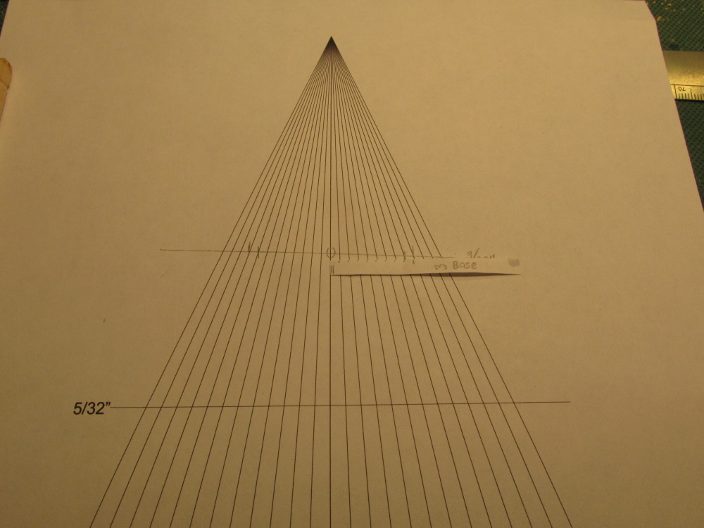
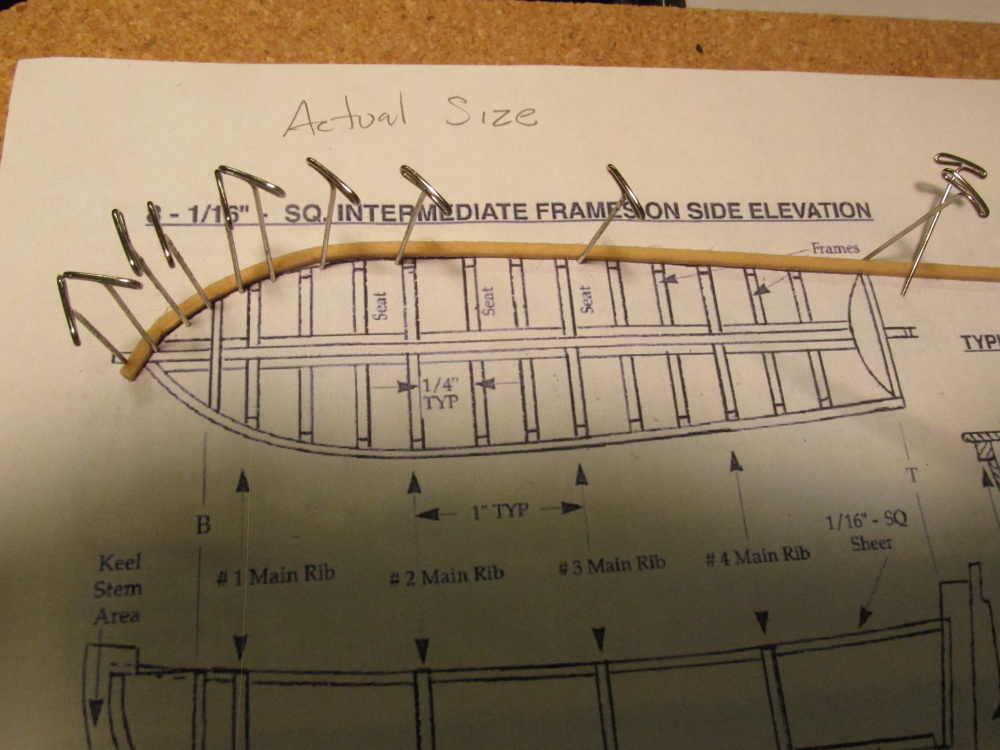
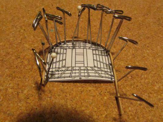
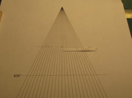
The Sheer Line The sheer line is made of 1/16” x 1/16” basswood. I debated whether to substitute teak for that or not and decided it would be easier to bend the basswood. I could always stain it to add an accent to the look of the boat if I didn’t like the way it looked against the teak. Because the plans are the same of all sizes of the kit, the plans were reduced to match the size of my kit. The basswood was soaked for a day and pre-bent using a copy of the reduced plans to pin and bend the wood.

- 93 replies
-
- 3
-
-
- ships boat
- model shipways
- (and 1 more)
-
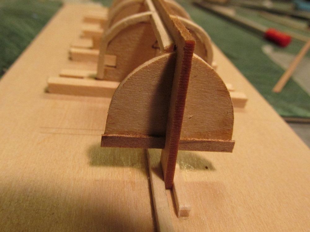
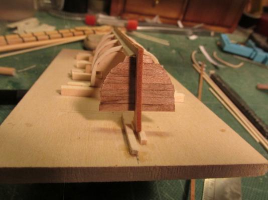
Because the planking will cover the edges of the transom, the transom had to be planked first. I chose to do this prior to installing the sheer line rail which the instruction would have me make next. The wood provided in the kit is basswood, a soft light colored material. I had a piece of teakwood at my disposal which I had obtained and described earlier in my Rattlesnake build log and decided to use it for the planking. The basswood planks were 1/32” x 3/32”. If the Rattlesnake is 1:64 scale then so must be the boat. A plank 1/32” thick would translate to 2” on the real boat, a bit excessive I thought. I first cut a teak plank to 1/64” x 3/32” which by the way is a piece of cake with the Byrnes saw but found that although the wood held up fine, it was a been too flexible. The resulting model would have felt like it was made out of paper. The next piece I made a tad thicker and that seemed to work. I planked the transom. The second photo is before any trimming.

- 93 replies
-
- 2
-
-
- ships boat
- model shipways
- (and 1 more)
-
Transom Following the instruction I had glued the laser cut transom into place and noticed it left a 1/16” gap where it met to top of the notch in the stern post. Assuming there was a reason for this that would make it presence know, I left it. It didn’t Looking at the plans, no gap is shown. Using a piece of 1/16” x 1/16” basswood, I filled it in
-
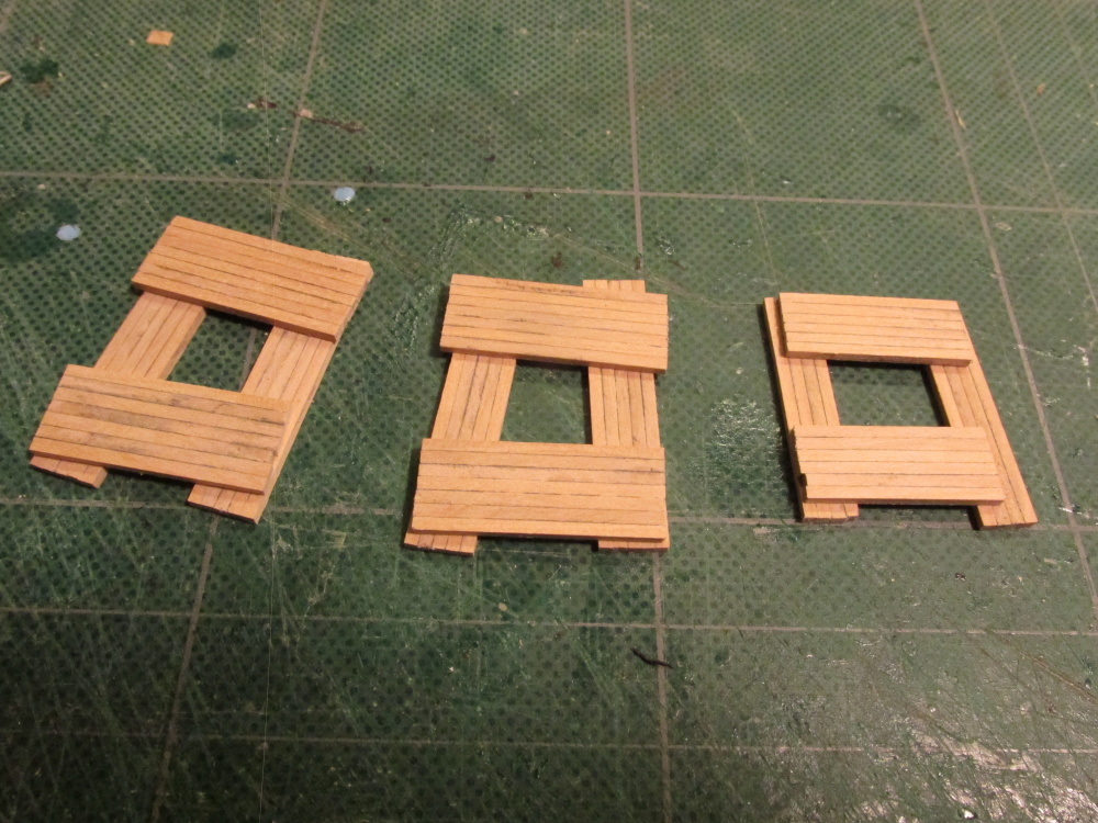
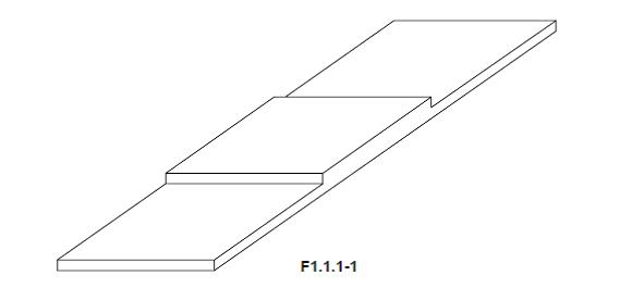
When done each platform will consist of four components, front, back and 2 sides that are in effect, lap joined together. To make the lap joint, the thickness on the outer third (approx.) of each end of the component has to be reduced by half to 1/64”. This is what has been so frustrating. Just sanding the edge joined components cause the pieces to break apart which required regluing. Reducing the thickness also causes the components to fall apart. After all, the glued surface is only 1/32” to begin with. The Practicum claims that the reduction can be performed with an Exacto knife. How one can maintain that tolerance using a hand tool is not explained. My plan of attack was to use the Byrnes saw. I set the blade to a height of 1/64” and by cutting a groove one blade width at a time, I can create the required rabbet assuming the piece don’t fall apart again, which unfortunately they have. The diagram and photograph are from the Practicum.

-
Mast Tops The mast tops is a study of taking long sticks of wood, chopping them up into smaller sticks of wood and reassembling them into something that resembles a platform. If you have noticed I have sloooowwwed way down in my postings, not so much as from inactivity, but frustration and lots of do overs. The tops are made from 1/32” square boxwood which was cut to size anywhere from 15/16” to 1 ½” in length depending on the mast and whether it’s the front/back or side portion of the platform. The 4 to 7 pieces boxwood are then edged CA glued together again depending on the part.