-
Posts
2,646 -
Joined
-
Last visited
Content Type
Profiles
Forums
Gallery
Events
Everything posted by JSGerson
-
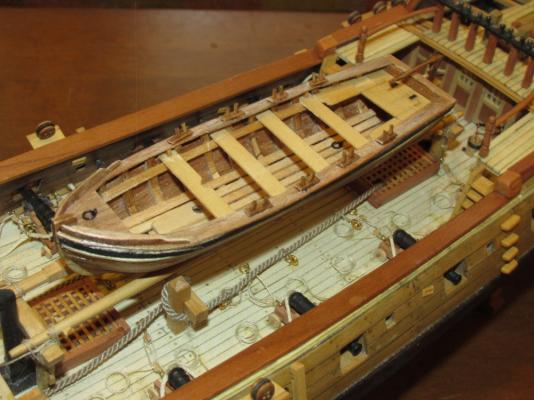
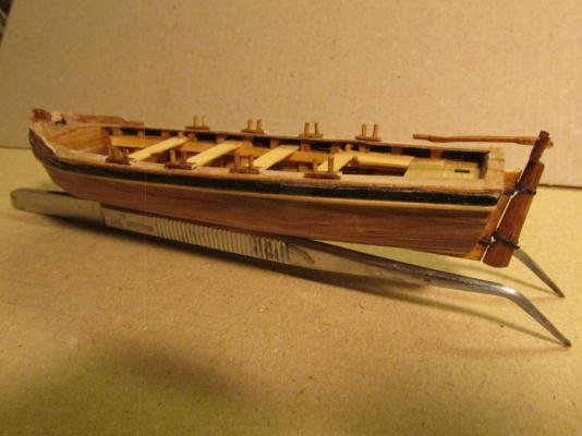
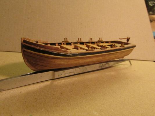
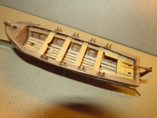
Boat Oars What is a boat without oars? The kit was for the boat only; any accessories, you were on tour own. I based the oars for this boat on The Art Making Masts, Yards, Gaffs, Booms, Blocks and Oars as Practiced in the Royal Navy and According to the Most Approved Methods in the Merchant Service, 2nd edition, printed for Steel and Goddard, London, 1816. It’s English Royal Navy and published later than the Rattlesnake 1781 commission date, but it was the best reference I had. I’m guessing that any differences between an English boat oar and an earlier American boat oar would be minor and not too noticeable at this scale (I hope).
- 93 replies
-
- ships boat
- model shipways
-
(and 1 more)
Tagged with:
-
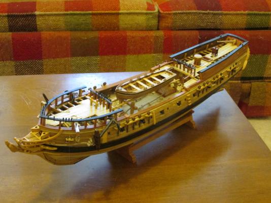
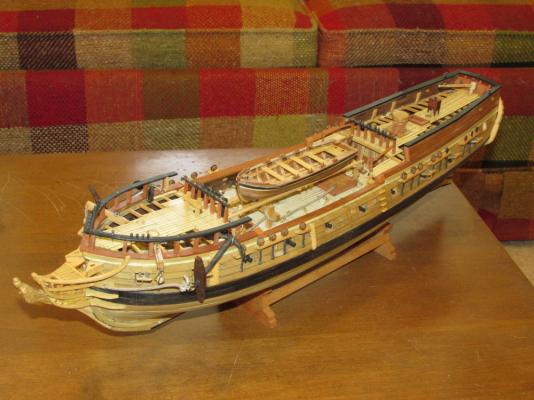
PLEASE NOTE Dear Readers, it has been brought to my attention that more than a dozen or so images in this log have vanished for some unknown reason. You can see the frame, but no picture. Twice now I've had to go back and replace the missing images. If anyone knows how to prevent this, please let me know. If anyone notices images missing please let me know so that I may replace them. Unfortunately, some of those image were provided by you, the reader in your comments to me so I can't replace them. If they are yours, please be so kind to repair your comments. Thanks Jon
- 974 replies
-
- rattlesnake
- mamoli
-
(and 1 more)
Tagged with:
-
I'm working on the oars, so stay tuned
- 93 replies
-
- ships boat
- model shipways
-
(and 1 more)
Tagged with:
-
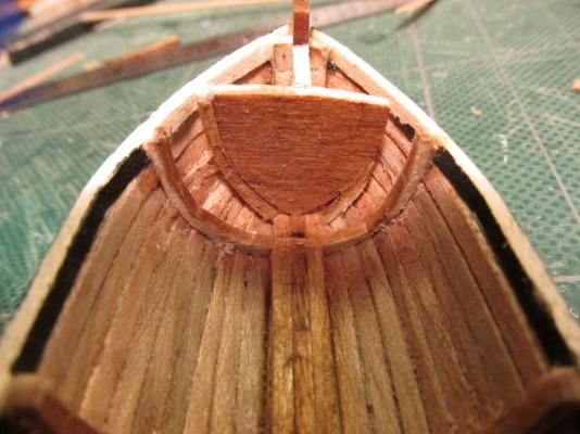
FINAL THOUGHTS Here are some final thoughts based on a question I received from bandlc4 This was my first small boat build, as well as my first upside down build, and my first Plank on Frame build, so I was learning as I was going. The problem with the kit was that it was a $5 kit (on sale from $8). The Kit instructions stated that the keel was made of airplane plywood - it wasn't. It was basswood, the plywood would have been much stronger. The ribs on the jig had to be bent to form, I would have preferred that they had been cut to shape and there were all of ribs at the beginning and not stuck on later. That would have provided the planking strips with more support and insured proper shape. I would have preferred boxwood which is hard wood instead of the soft basswood. Another builder on the same model started over and replaced all the wood with boxwood and pear. Neither one of us planned to paint the boat. When I went to create the top cap, I realized that my bow stuck out further on the stem than the plans showed. I thought I was following the plans meticulously, but because the plan's pictures were of such low resolution, you couldn't see the detail in the bow clear enough. As a result, my bow bulkhead ended up too small for what I built - my bow should have curved more tightly to the stem and then the bulkhead would of fit (I assume). Although this is a small, "simple" model, I would not call it a first timer's model for it requires some boat building experience. If I had to build it again, and I could because the plan shows all the parts to scale, I'd cut the ribs to shape, which I find much easier than to bend, and add more of them to the jig. The hard part would be to create the additional ribs where the hull curves toward the bow. Not sure how I would determine the correct shape for the ribs there. That would ensure the bow bulkhead fits. By the way, the other builder I mentioned ran into the same problem with that bulkhead. That all being said, it was a fun build and a good learning experience. I hope I answered your question and I wish you the best in your endeavor. Jon
- 93 replies
-
- ships boat
- model shipways
-
(and 1 more)
Tagged with:
-
- 93 replies
-
- ships boat
- model shipways
-
(and 1 more)
Tagged with:
-
- 93 replies
-
- ships boat
- model shipways
-
(and 1 more)
Tagged with:
-
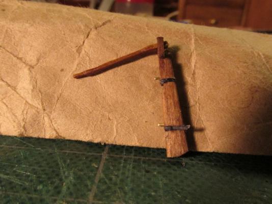
After the pieces were assembled, the basswood parts were stained with Early American and I added paper hinges colored black with a Sharpie pen. Because where the rudder post edge and the rudder edge meet are rounded, it made for a poor mechanical glue point. I added a couple of pins for a strong joint.
- 93 replies
-
- ships boat
- model shipways
-
(and 1 more)
Tagged with:
-
I had noticed that a lot of tillers pivoted vertically either for storage when the rudder was removed or for easier access to the boat. Although I didn’t plan on mine being functional, I wanted it to look like it could move. This required two short pieces to be added to the tiller post. The tiller itself was carved with a slight S-curve.
- 93 replies
-
- ships boat
- model shipways
-
(and 1 more)
Tagged with:
-
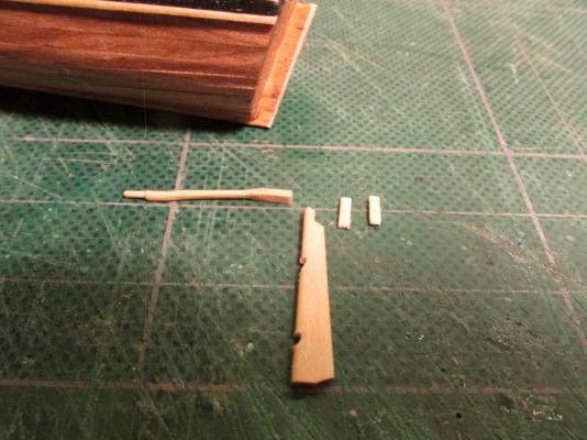
After looking at a lot of small and ship’s boats, I came to the conclusion that most of the boats I saw did not have the high stem post, so I chose to leave it off. Had I straight glued the broke piece back on, it would have remained fragile which would mean I would have had to pin it and risk breaking it some more. All that being said, the rudder was now too tall for what I wanted to do so, the tiller post was cut down a bit.
- 93 replies
-
- ships boat
- model shipways
-
(and 1 more)
Tagged with:
-
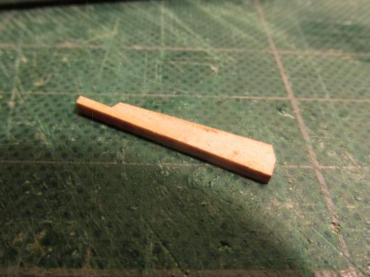
The Rudder The kit provided a precut basswood rudder which I used. However, you remember I broke the top of rudder stem where it protruded above the transom. The two images below show the before and after the break
- 93 replies
-
- ships boat
- model shipways
-
(and 1 more)
Tagged with:
-
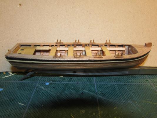
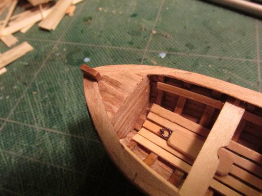
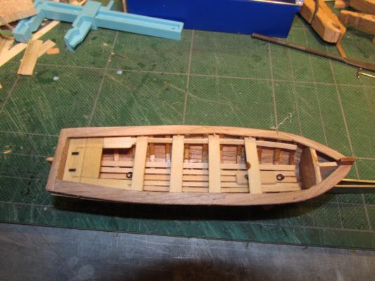
A strip of wood, which I think is called a washboard, was added to each side of bow as well another eyebolt and ring to the bow deck. Also notice that the oarlocks were moved after I was informed that I had inadvertently installed them on the wrong side of the thwarts. As originally installed, the rowers would have to face forward and row the boat backwards.
- 93 replies
-
- ships boat
- model shipways
-
(and 1 more)
Tagged with:
-
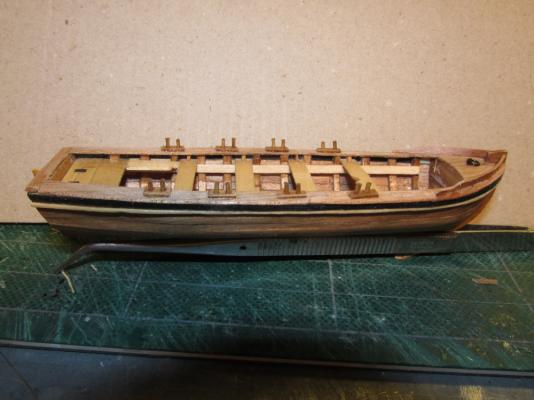
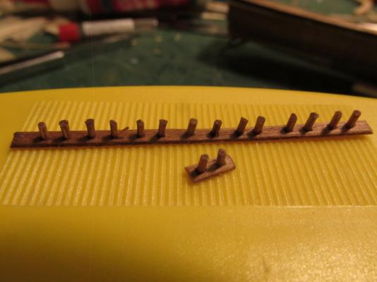
The oarlocks were made of bamboo pieces just like one would make treenails, about a quarter the width of the soon to be made oars (about 1/32”) and placed into a pre-drilled kit supplied basswood planking strip. Initially the holes were drilled and the oarlock inserted. Their heights were adjusted and then the whole assembly was stained with Early American. The stain temporarily “glued” the bamboo into position. After the stain dried, the excess was cut off from the bottom and sanded smooth. The oarlock assemblies were then cut off and glued into position onto the rail cap locking everything – the rail cap, oarlock plate, and the bamboo with a single dab of CA glue.
- 93 replies
-
- ships boat
- model shipways
-
(and 1 more)
Tagged with:
-
- 93 replies
-
- ships boat
- model shipways
-
(and 1 more)
Tagged with:
-
- 93 replies
-
- ships boat
- model shipways
-
(and 1 more)
Tagged with:
-
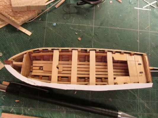
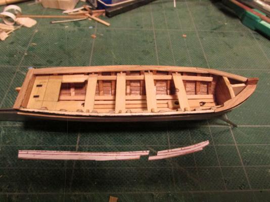
The top rail was made using a template traced from the model. If I had made the model perfect it would have matched the plans and I could have just cut the template directly from them. Since it wasn’t, I couldn’t. Each side template had to be cut in two places to create the splines for the three pieces of 1/32” x 3/32” Teakwood to accommodate the boat’s curve. The top of the transom was ¼”.
- 93 replies
-
- ships boat
- model shipways
-
(and 1 more)
Tagged with:
-
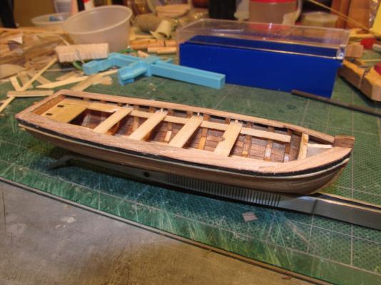
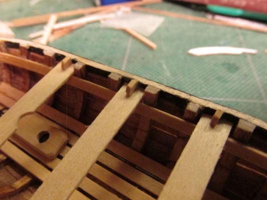
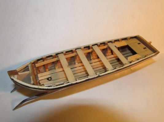
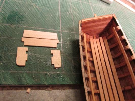
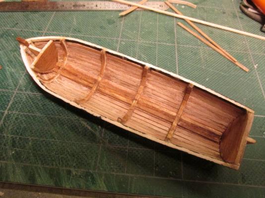
I noticed on many models, that the thwarts had little braces (knees) securing them to the hull so I added those. I tried to round the corners, but they were so tiny I could barely hold them steady, let alone file them. As it turned out in the end, you can hardly see them.
- 93 replies
-
- ships boat
- model shipways
-
(and 1 more)
Tagged with:
-
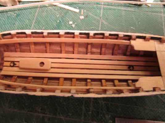
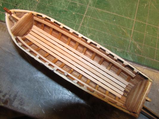
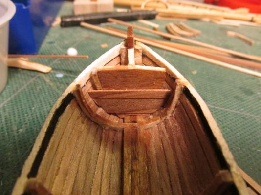
The seat pieces were cut and trimmed to fit and glued into place. The “hinges” are nothing more than pieces of black paper that were added when I Poly-wiped the wood. The remainder of the thwarts (seats) were supported by the risers (support strips). The forward thwart had a half round notch cut out for an optional mast.
- 93 replies
-
- ships boat
- model shipways
-
(and 1 more)
Tagged with:
-
It seemed to me that all ship’s boats are basically the same at this stage of the build. Looking at all of my 46 Rattlesnake models images that I have collected from the internet, I selected the ones with clear/detailed images of the ship’s boat. Not one of them duplicated any other’s boat. Everyone was different. That meant I had free rein as to what mine was going to look like. Taking elements from the kit itself, the Practicum, other boats on or off the Rattlesnake, and reference books, I came up with my version. Like most boats, I created a backseat with two side seats. Some of the models I had seen had a lid over the back seat so I thought that would be neat to have. The lid was simply etched into the wood. Additionally I added a mast block (my own design since I didn’t have much to go on) and some brass rings fore and aft colored black with a Sharpie pen.
- 93 replies
-
- ships boat
- model shipways
-
(and 1 more)
Tagged with:
-
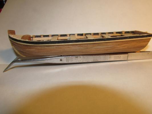
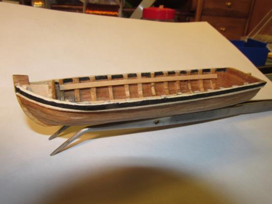
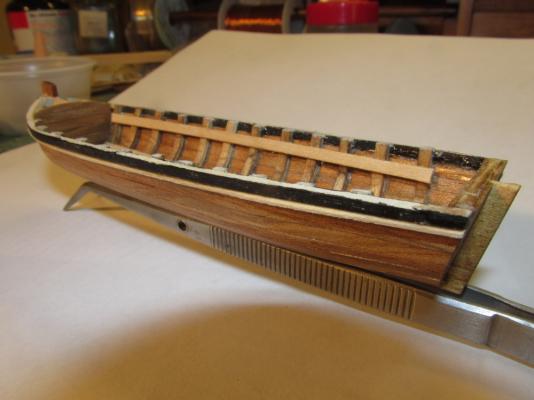
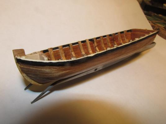
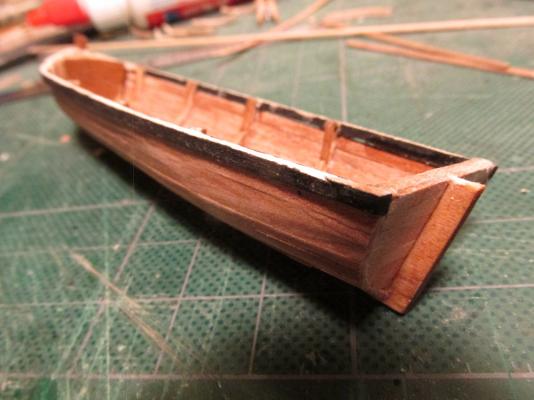
At this point I decided that the exterior still needed something, so I added a piece of unstained 1/32” x 1/32” basswood right up against the sheer plank. It did two things. First it added a little snap to the boat. I had seen other small boats with similar structures. Second, it covered up small gaps between the planking and the sheer plank. The basswood piece was cut from the 1/32” x 3/32” basswood planking stock that came with the kit. I actually made two strips from one plank! Boy, I love that Byrne’s saw!
- 93 replies
-
- ships boat
- model shipways
-
(and 1 more)
Tagged with:
-
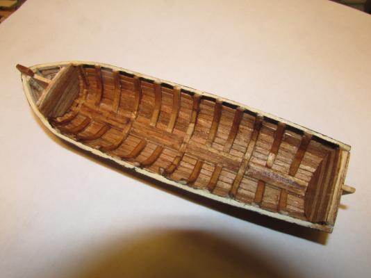
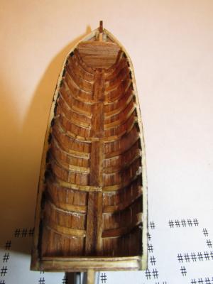
Basswood planking stock was added as the interior floor boards and for a change, there were no hassles. I left this basswood as well as the other basswood in the interior unstained to provide a contrast between the interior and the exterior of the boat.
- 93 replies
-
- ships boat
- model shipways
-
(and 1 more)
Tagged with:
-
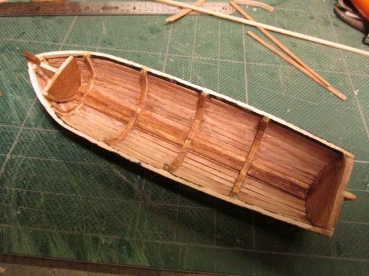
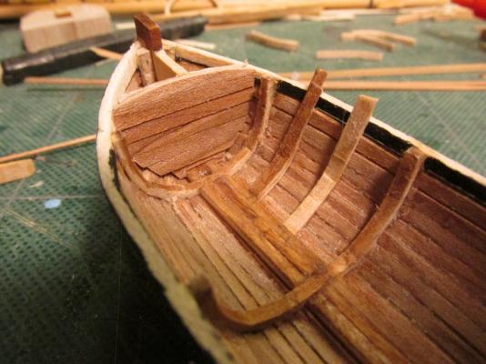
Following the kit plans, additional ribbing was added. The ribs were made of the kit’s basswood but not the bass designated for it. Instead I used the unused planking material which was half the intended thickness. Two pieces were cut to size, soaked, bent, and laminated together. The bending was much easier that the original ribs on the building jig. They were glued to the inside of the hull, trimmed, and stained. The whole hull was then coated with Wipe-on Poly.
- 93 replies
-
- ships boat
- model shipways
-
(and 1 more)
Tagged with:
-
Using the Teak planking I made for the hull, a new bulkhead was veneered over the original. The same was done to the transom to match.
- 93 replies
-
- ships boat
- model shipways
-
(and 1 more)
Tagged with:
-
You will notice that the pre-cut bow bulkhead was too small and I had to beef it up during planking so it was not a pretty sight.
- 93 replies
-
- ships boat
- model shipways
-
(and 1 more)
Tagged with:
-
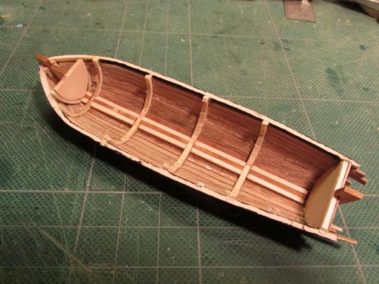
The excess planking was removed at the stern, but in the process the unsupported stem post above the hull broke off. That was because the grain of the wood was horizontal so it had no strength. A sneeze could have knocked it off so it wasn’t unexpected. If the stem post had been constructed like a real boat, the grain would have been vertical but because this was a very cheap kit (I paid $5.00 on sale, otherwise $8.00) a lot of detail was spared. I will address this later. The light colored basswood ribs and keel looked like tan lines against the darker Teak so I stained them with Early American 230 Minwax Wood Finish (what else?) to match the Teak.
- 93 replies
-
- ships boat
- model shipways
-
(and 1 more)
Tagged with:
About us
Modelshipworld - Advancing Ship Modeling through Research
SSL Secured
Your security is important for us so this Website is SSL-Secured
NRG Mailing Address
Nautical Research Guild
237 South Lincoln Street
Westmont IL, 60559-1917
Model Ship World ® and the MSW logo are Registered Trademarks, and belong to the Nautical Research Guild (United States Patent and Trademark Office: No. 6,929,264 & No. 6,929,274, registered Dec. 20, 2022)
Helpful Links
About the NRG
If you enjoy building ship models that are historically accurate as well as beautiful, then The Nautical Research Guild (NRG) is just right for you.
The Guild is a non-profit educational organization whose mission is to “Advance Ship Modeling Through Research”. We provide support to our members in their efforts to raise the quality of their model ships.
The Nautical Research Guild has published our world-renowned quarterly magazine, The Nautical Research Journal, since 1955. The pages of the Journal are full of articles by accomplished ship modelers who show you how they create those exquisite details on their models, and by maritime historians who show you the correct details to build. The Journal is available in both print and digital editions. Go to the NRG web site (www.thenrg.org) to download a complimentary digital copy of the Journal. The NRG also publishes plan sets, books and compilations of back issues of the Journal and the former Ships in Scale and Model Ship Builder magazines.


