-
Posts
2,649 -
Joined
-
Last visited
Content Type
Profiles
Forums
Gallery
Events
Everything posted by JSGerson
-
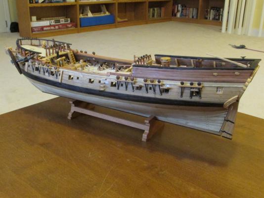
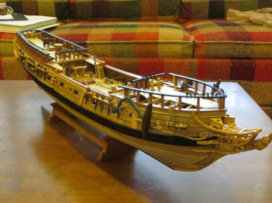
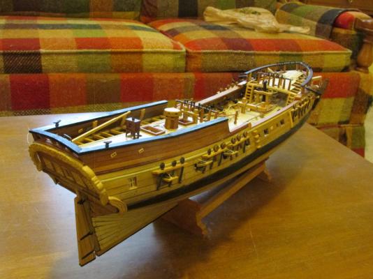
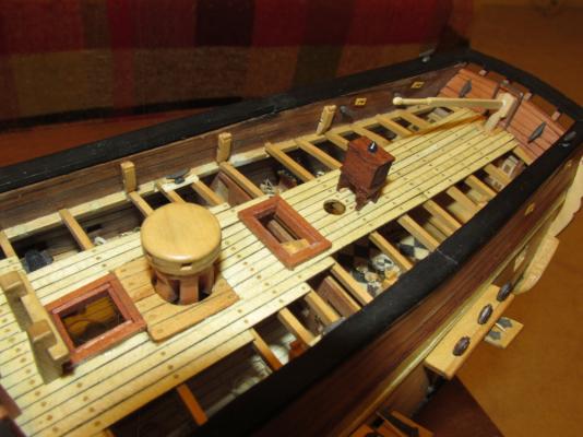
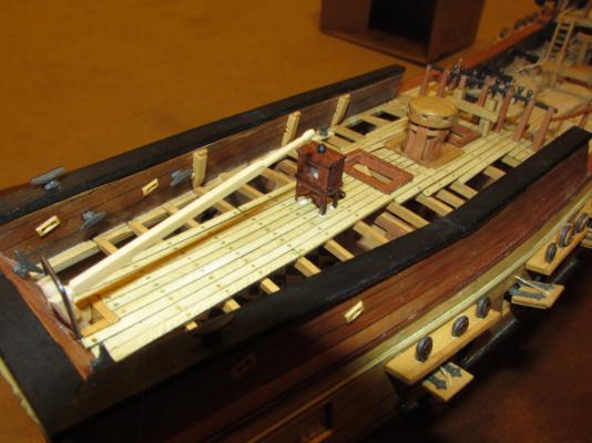
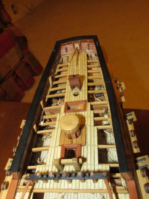
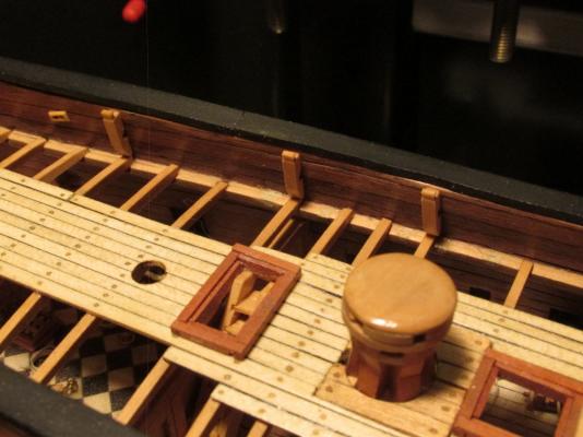
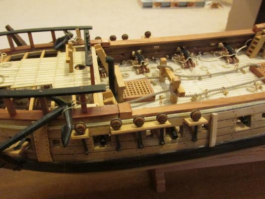
At this point, according to the Practicum, the hull is complete. What is left in Chapter nine of the Practicum to complete is the ship’s boat and the spare masts it rests on; and maybe a tweak or two here and there. Here are a couple of parting shots. Well, it not perfect. I would have been very surprised if it was but it will have to do.
- 974 replies
-
- rattlesnake
- mamoli
-
(and 1 more)
Tagged with:
-
- 974 replies
-
- rattlesnake
- mamoli
-
(and 1 more)
Tagged with:
-
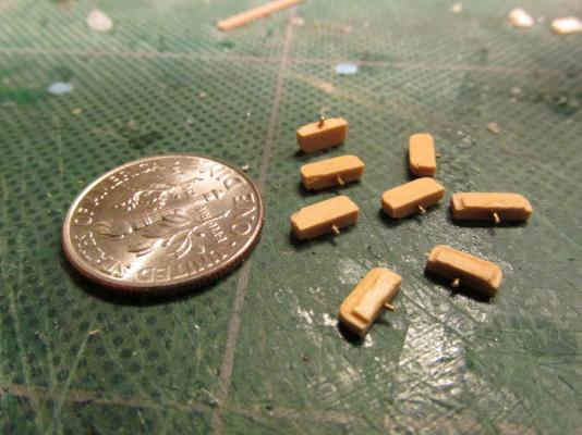
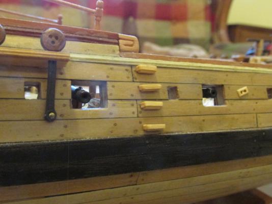
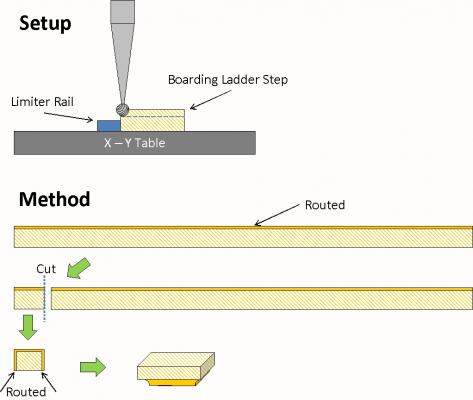
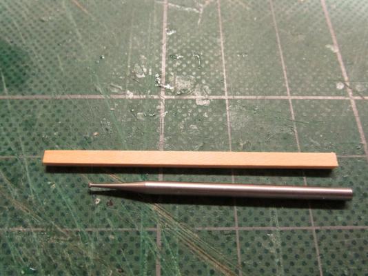
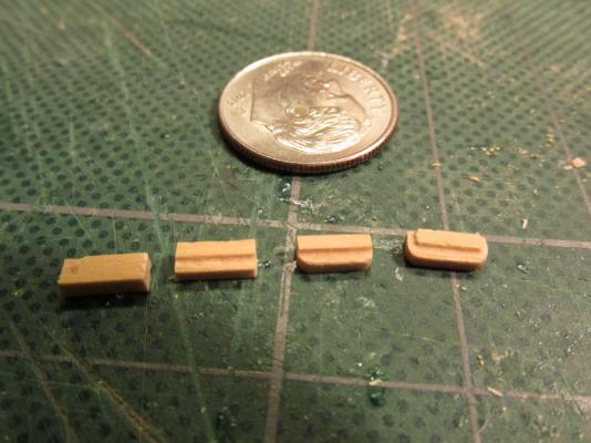
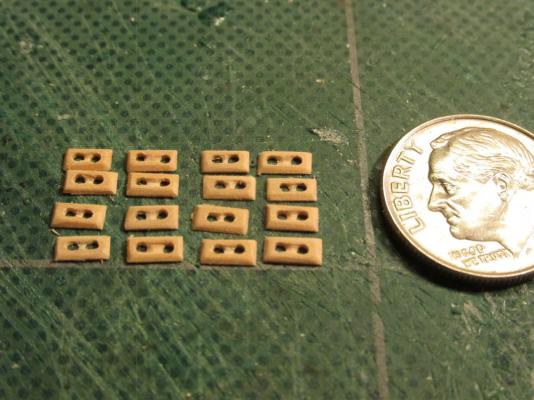
Boarding Ladders Surprisingly (or not) the Practicum also does not address the boarding ladder, those little steps on the outside of the hull. Mamoli does have an illustration as to how to construct them but I didn’t like the looks of it when I reviewed how other models made theirs. they were to be made with stacked upside down L-shaped channels. So to put it into technical terms, I winged it. Based on the picture of the steps I “guestimated” their dimensions. The steps are not simply slabs of wood stuck to the side of the hull. They appear to be either two layers of wood, one smaller than the other, or one thick piece carved. Because of the size of the step pieces, I chose to make each out of one piece of wood. I converted my rotary drill into a pseudo router again using a dentist sized ball burr tip as my cutter. A piece of 1/16” x 3/32” boxwood about 2” long was placed into my pseudo router to cut an inverted rounded corner along the whole length of wood strip. Then eight ¼” pieces were cut, four steps for each side of the model. The new two edges of each piece were then “routed” leaving the fourth side untouched.
- 974 replies
-
- rattlesnake
- mamoli
-
(and 1 more)
Tagged with:
-
Miscellaneous Stuff It was time to install three more items to the deck, two of which I had previous fabricated. First the tiller was added to the rudder post and the binnacle was glued to the deck. The third item, the “iron horse” was not addressed in the Practicum. This piece is nothing more than an upside down square shaped “U” wire structure behind the rudder post. Seemed simple enough, but because of the problems I encountered earlier with the transom and quarter deck, I had little room for its installation. My rudder post was practically against the transom. So being technically minded and handy with the tools, I fudged it, artistic license…so sue me. The kit called for brass wire, but that is very soft and therefore deforms very easily. I chose to use music (piano) wire. It’s dark in color and very stiff. My “horse” had to go above the rudder post for clearance due space considerations I mentioned earlier. As a result, mine looks a bit tall and narrow as opposed shorter which would make it look squatter.
- 974 replies
-
- rattlesnake
- mamoli
-
(and 1 more)
Tagged with:
-
Igor - I understand, that was my intention. They ended up looking like they do because they were based on the measurement from Hahn's plans which my model pretty much approximates. It should be an exact match but somehow it didn't work out that way. It's easy to draw lines on an image to get the exact angle but I wasn't quite certain how to do it with accuracy on the model itself. I suppose I will have to adjust them in the future when I know better where the lines will actually be. Thanks for your insight.
- 974 replies
-
- rattlesnake
- mamoli
-
(and 1 more)
Tagged with:
-
All of this rigging stuff is new to me so I am watching you and Blue Ensign closely. I am getting very close to finishing my Rattlesnake hull and will have to tackle this phase of the build soon. My apprehension grows daily. But like all things, I will take it one step at a time and hope I don't screw it up too badly.
- 104 replies
-
- rattlesnake
- mamoli
-
(and 1 more)
Tagged with:
-
The Byrnes saw is a great piece of precision and workmanship. I could not have done many of the things I did without that saw. I also have his dimensional sander and draw plate. I met Jim and his wife at the Nautical Research Guild convention in Charleston SC this past October and they are great people as well. He allowed me to buy an accessory to the saw with no money provided I went online and ordered it when I got home. And because I got it from him directly at the convention, he made sure to deduct the automatic charge for shipping. He backs up his products.
- 974 replies
-
- rattlesnake
- mamoli
-
(and 1 more)
Tagged with:
-
The easy part is gluing them into place. Note two of the kevels are attached to aft rail post where the anchor is tied. The anchor had to be re-tied after the kevel was attached.
- 974 replies
-
- rattlesnake
- mamoli
-
(and 1 more)
Tagged with:
-
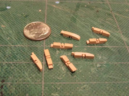
A chesstree is essentially the same as a kevel except it is installed on the outside of the hull and does not have a knighthead.
- 974 replies
-
- rattlesnake
- mamoli
-
(and 1 more)
Tagged with:
-
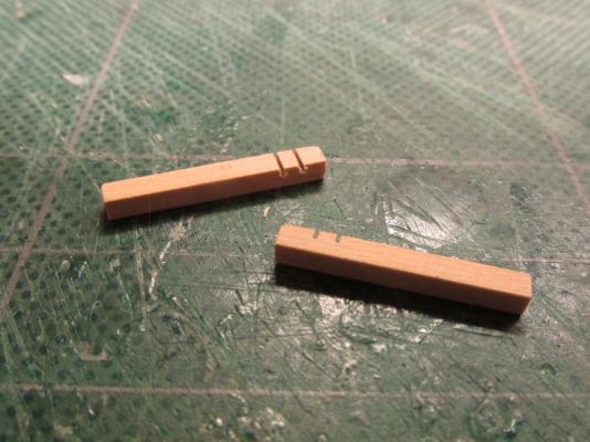
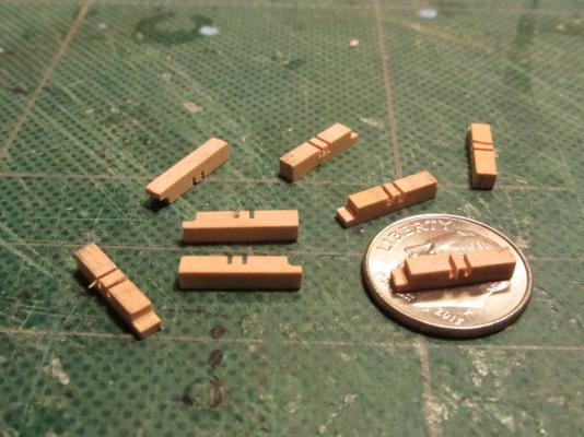
Using a very fine chisel, the wood material between the lower horizontal cuts was carved to look like the side of a wheel when it will glued in place. Care must be taken here because even a slight slip may cause the chisel to slice through the tiny piece of wood between the cuts.
- 974 replies
-
- rattlesnake
- mamoli
-
(and 1 more)
Tagged with:
-
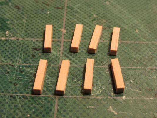
Kevels and Chesstrees A kevel is basically a post with a sheave in it. The Practicum calls for eight 3/32” square boxwood ½” long pieces. Once more, like the hull sheaves, Mr. Hunt uses one hole for the sheave. I elected to follow the Mamoli plan which shows two. Actually it shows a representation of pulley wheel as well. Because the side that is to be glued to the inside of the hull is exposed during fabrication, it is possible to create a pseudo wheel which I did. Using my Byrnes saw, I made three 3/64” deep cuts across the side and one more across the top to create a notch for the knighthead. It looks like the knighthead is used to tie off and hang excess line.
- 974 replies
-
- rattlesnake
- mamoli
-
(and 1 more)
Tagged with:
-
Oh, I like your idea using the Xacto blades for scrapers which allows you the use of a handle! (I had been using a razor blade) Cutting the metal scraper was easy; cutting the metal scraper to the exact profile and proper width I found difficult. Your moldings came out looking real good. I'm not clear how you are making the hinges out of rings so I guess I will have to be patient and just wait to see what you do next.
-
I took a look at my collection of 34 different model Rattlesnake's build pictures that I have assembled over the past four years of my build. Of the completed models that were painted and that had bill boards, some were black in color and others natural wood. Just remember that the purpose of the bill board is to take the abuse of the anchor so it doesn't mess up the hull. I would imagine a lot of pieces have to be replaced over time as the wood wore down and keeping it painted would be a pain. So I guess the choice is yours - make it look good or make it more realistic.
-
The anchor board thing is called a billboard because the flukes on the anchor are called bills. The board provided added strength for wear and tear as the anchor is hauled aboard the ship. You can see how I handled it here: http://modelshipworld.com/index.php?/topic/2293-rattlesnake-by-jsgerson-building-robert-hunt%E2%80%99s-kitbashed-mamoli-american-privateer-a-164-scale-pob-model/page-27
-
The deck planking on my model was done per the plans: A false deck made of a single piece of thin wood that came with the kit was installed after the bulkheads were glued to keel.This was the foundation for the deck planking. Where I kit bashed the cabin floor with a checkerboard (per Robert Hunt's Practicum} there is an additional layer to support the the checkerboard. The combined thickness of the support and the checkerboard pieces equals the thickness of the deck planks so there is no difference in height. To ensure that the gun ports were of proper height from the deck planking, I created a heavy stock card cannon. If the cardboard cannon could slide easily through the gunport, it was OK. Other decks (quarterdeck and forecastle) were planked directly onto the ships beams. As for other methods, I can only assume that any change from a kit's plans must be compensated for any change in overall dimensions. This is my first model of this type so I am a bit limited in experience. I don't know if I have answered your question but maybe some other readers of this log can jump in with their ideas.
- 974 replies
-
- rattlesnake
- mamoli
-
(and 1 more)
Tagged with:
-
I too have Byrnes draw plate and it is worth the money. Someone once said they don't like models that have the Measles. If you look a actual ships the treenails are subdued almost to the point of disappearing on some decks. For that reason I did nothing to enhance the treenail contrast. I used bamboo skewers I bought at the grocery store, split them down, and then used the draw plate. They were "glued" in place with Poly-wipe, the same treatment I applied to the whole deck and hull planks. Because the grain of the treenails are perpendicular to the surface, it draws in the Poly-wipe and darkens them just enough so you can see them, but not enough to overwhelm the senses. It's a matter of taste of the builder. Just my 2 cents.
-
I collected Pasi's build log as he was creating it and copied it to a Word file for my own use. It's not the complete log as I have deleted what I felt were non essential comments from other followers or I have deleted their screen names if I kept their comments. Because it's edited and technically it's Pasi log. I don't know if I have the right to distribute it. If you can get Pasi's or the Moderator's permission, I would gladly send it to you. Moderator, can I distribute another member's build log without his permission?
- 974 replies
-
- rattlesnake
- mamoli
-
(and 1 more)
Tagged with:
-
Scott - This week finds me visiting my spry 95 year old Mom in Florida, so no work on the model till I return. According to the Practicum, there are just a few more items to add to the deck ( sheave structures, cleats, spare masts, etc.) then the last major piece, the ship's boat, which is a little model unto itself. At that point I will have completed all nine chapters of the Practicum for creating the hull. Then the real fun begins - starting the Practicum for the masts, yards, and rigging!
- 974 replies
-
- rattlesnake
- mamoli
-
(and 1 more)
Tagged with:
-
I've got to believe what I read somewhere that Bob took a lot of short cuts near the end of the hull building in his Practicum. He stated somewhere earlier that he was building four models and writing their Practicums at once and had deadlines to meet. That would explain why he never finished his model hull or rigged it. At least he provided detailed interpretations of the rigging plans so we could finish. Still, all things considered, if I had to start over, I'd still buy his Practicum. There is a wealth of experience and knowledge there.
- 974 replies
-
- rattlesnake
- mamoli
-
(and 1 more)
Tagged with:
-
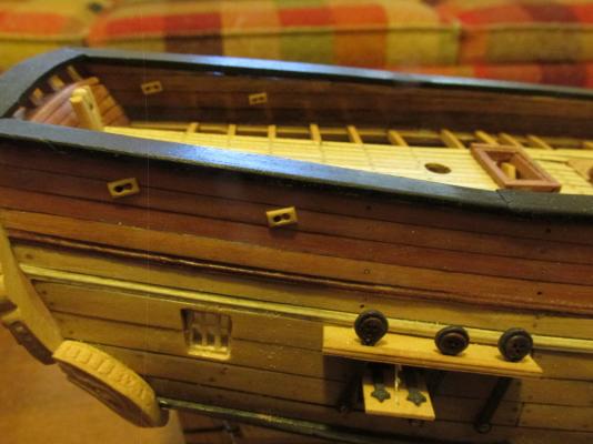
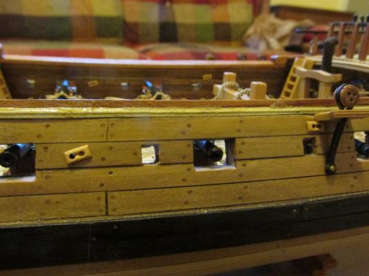
The blocks were first glued into position on the outer hull. Only one hole had to be drilled through the hull to the inside wall where the line passes through. The other hole in the block is just for show. For the inside sheave block, glue was applied to the block, a pin was place in one of the sheave block holes and then the pin with the block was stuck into the hole in the bulwarks. The sheave block was then slid off the pin and orientated on the bulwark and the pin removed. A final coat of Poly Wipe on the block and it’s done. It sounds way more complicated than it really was.
- 974 replies
-
- rattlesnake
- mamoli
-
(and 1 more)
Tagged with:
-
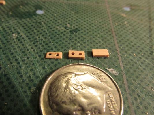
Hull Sheaves At first this looked like a straight forward simple install. A piece of 1/32” x 3/16” x 3/32” boxwood is to be glued to the outside of the hull and a hole drilled through until it passes through the bulwarks on the inside of the hull. Somehow this didn't look right. First, a sheave is a rope pulley built into the hull wall. That means it actually has two holes, one at the top of the pulley wheel and the other at the bottom. Second from what I could find, these were built flush with the hull; they didn't stick out of the hull. In order to install the sheave in the hull I would have to make a finely cut rectangular hole in the hull and fill it with a double-holed sheave block that could accept a “rope” to pass through it. This would require very high tolerances and I don’t have those skills. The sheaves should have been constructed before the hull was planked. I just didn't know then. Remember this is my first boat of this style. Why the Practicum didn't address this then, I don’t know. Therefore a compromise was required. Instead of a simple block of wood with a hole in it as depicted in the Practicum, I elected to make the block with a double hole and a shallow trough between them to give the impression of a pulley wheel inside. The practicum would have the builder make six of these blocks, for three sheaves on each side of the outside hull. There are in fact four sheaves. The fourth one is just under the aft deadeye channel of the foremast. This required that 16 (not 8 or 6) sheave blocks be constructed – 4 per side, outside the hull (8) and 4 per side, inside the hull (8) for a total of 16. This was accomplished by cutting 16, 3/16” long pieces of 1/32” x 3/32” boxwood. Two holes were drilled and a groove chiseled between the holes. Because I didn't want the blocks sticking out, the backsides of the blocks were sanded down as much as I dared to reduce the thickness and the edges tapered so that there were no sharp edges other than the rectangular shape. Without sharp edges hard shadows are hopefully reduced. The idea was to fool the eye into thinking the blocks were flush when they were installed.
- 974 replies
-
- rattlesnake
- mamoli
-
(and 1 more)
Tagged with:
-
Scott, I too was new to building POB models and the Rattlesnake was/is my first build (four years an still counting). In my case I am using the Mamoli kit following Bob Hunt's Practicum, and using a wood supplement package (all the gory details on my log). Don't be intimidated. If you break it down into small steps, progress will be made. I watch a multitude of logs and gleam every last detail to help with my build. Although I was intimidated by the quality of other builder's skills, I was encouraged to start my own log so others could learn from my mistakes and triumphs. Because of the log, it kind of gives you the incentive to keep going because others are watching you. That, and all the tips and suggestions you get from your followers. I hope to see your log soon, yes?
About us
Modelshipworld - Advancing Ship Modeling through Research
SSL Secured
Your security is important for us so this Website is SSL-Secured
NRG Mailing Address
Nautical Research Guild
237 South Lincoln Street
Westmont IL, 60559-1917
Model Ship World ® and the MSW logo are Registered Trademarks, and belong to the Nautical Research Guild (United States Patent and Trademark Office: No. 6,929,264 & No. 6,929,274, registered Dec. 20, 2022)
Helpful Links
About the NRG
If you enjoy building ship models that are historically accurate as well as beautiful, then The Nautical Research Guild (NRG) is just right for you.
The Guild is a non-profit educational organization whose mission is to “Advance Ship Modeling Through Research”. We provide support to our members in their efforts to raise the quality of their model ships.
The Nautical Research Guild has published our world-renowned quarterly magazine, The Nautical Research Journal, since 1955. The pages of the Journal are full of articles by accomplished ship modelers who show you how they create those exquisite details on their models, and by maritime historians who show you the correct details to build. The Journal is available in both print and digital editions. Go to the NRG web site (www.thenrg.org) to download a complimentary digital copy of the Journal. The NRG also publishes plan sets, books and compilations of back issues of the Journal and the former Ships in Scale and Model Ship Builder magazines.


