-
Posts
2,611 -
Joined
-
Last visited
Content Type
Profiles
Forums
Gallery
Events
Everything posted by JSGerson
-
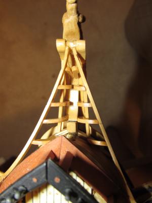
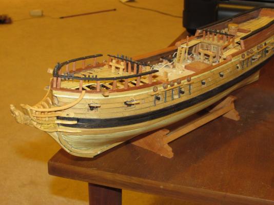
Due to the errors that I made during the early part of the transom construction which I think I discussed at length, I knew I would have problems with the rudder post. On my model, I had to make the rudder post opening butt against the transom and even then I had to fudge a bit with the post. Actually I made the rudder post at the same time I made the post opening using the post as a guide to position the opening. Once I knew they would fit I put the post aside till it was time to use it. As for the tiller, I don't think I will have a problem due to the fact the rudder post is so far back. The conference was great. Over the course of 4 days, we had 12 speakers and 3 tours. The speakers were excellent, all top notch experts in their areas. They talked everything restoring actual relics including the USS Monitor, modeling techniques, history of private boat building in Racine WI, among others. The tours included touring 3 WWII warships (carrier, destroyer, & sub), visiting the first sub to sink a warship, the Hunley, and a tour of Ft. Sumter. So I'm planning to go to St. Louis next October for the next conference.
- 974 replies
-
- rattlesnake
- mamoli
-
(and 1 more)
Tagged with:
-
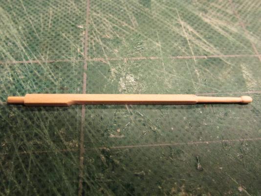
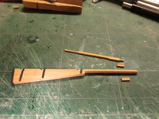
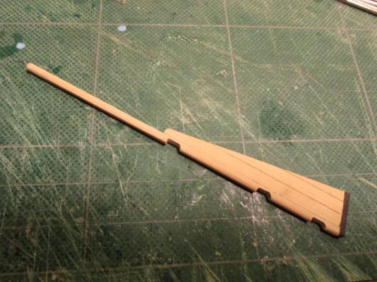
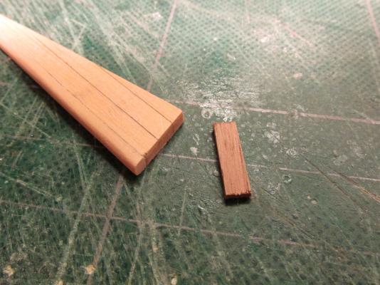
In a sentence that could be easily overlooked, the Practicum instructs the builder to drill a 1/16” hole in the rudder post for the tiller and then goes silent on the construction of the tiller for another 23 pages. I decided to construct the tiller now while everything was off the model and easy to manipulate. The Practicum instructs the builder to use 1/16” x 3/32” boxwood to make the tiller. That’s it, no other instruction on shape. The 3 plans show a simple straight rod going through the rudder post. The Mamoli and MS plans show some reinforcing blocks where the tiller passes through the post but no real detail. Bob’s tiller looked quite nice and structural stronger than what the plans showed with no reinforcing blocks. The blocks would add the material and strength back that was drilled out for the tiller hole. So my tiller is based on Bob’s photo of his tiller and the reinforcing blocks.
- 974 replies
-
- rattlesnake
- mamoli
-
(and 1 more)
Tagged with:
-
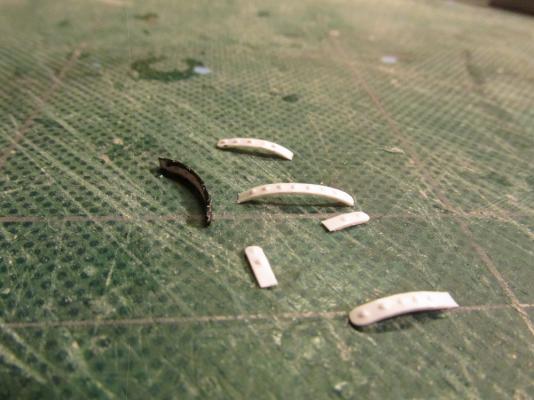
The Practicum claimed that the cast grudgeons and pinties parts that came with the kit were too thick and the spacing between the two sides was too large to use. The Practicum called for them to be made out styrene. Since they were to be painted black, there would be no hint as to what material they were made of. I suppose I could have made the pinties out of card stock or paper and the skipped the grudgeons since they would not be seen. But I didn't. If this were a larger scale model, I might have tried to make those pieces out of metal and blackened them (which by the way I’ve never done), but since it wasn’t, I didn't. I just wanted to let anyone know I did think about it. The Practicum called for the pinties to be made out of .015” x .060” styrene and the grudgeons .060 styrene rod. I used .050 styrene rod as I didn't have any of the other. It made no real difference. The pinties have rivets so using a dull but pointy instrument, I impressed on the backside of the styrene straps to make bumps on the opposite side. The straps were painted black except on their backside. I wanted a clean surface for the glue. In this case, I used “airplane” glue.
- 974 replies
-
- rattlesnake
- mamoli
-
(and 1 more)
Tagged with:
-
5/32” notches were then cut into the tiller edge to accommodate the grudgeons (pins) and pinties (straps). The notch had a top edge straight cut while the bottom curved. This was accomplished using the fine tooth saw from my miter box, a micro chisel, and some needle files. In hindsight, if I were to do this again I would have made the notches a bit longer, at least 3/16”. In order for the rudder to be removed, a working space of one strap as a minimum would be required. Therefore 2 straps widths and one strap space is about 3/16”.
- 974 replies
-
- rattlesnake
- mamoli
-
(and 1 more)
Tagged with:
-
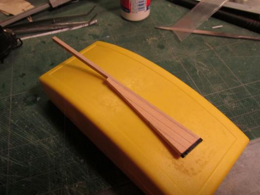
The false keel was added and the whole assembly was then shaped to match the keel thickness. The tiller edge was rounded over to allow the rudder to rotate even though it will be glued fixed in place. The false keel was then painted black.
- 974 replies
-
- rattlesnake
- mamoli
-
(and 1 more)
Tagged with:
-
- 974 replies
-
- rattlesnake
- mamoli
-
(and 1 more)
Tagged with:
-
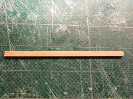
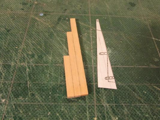
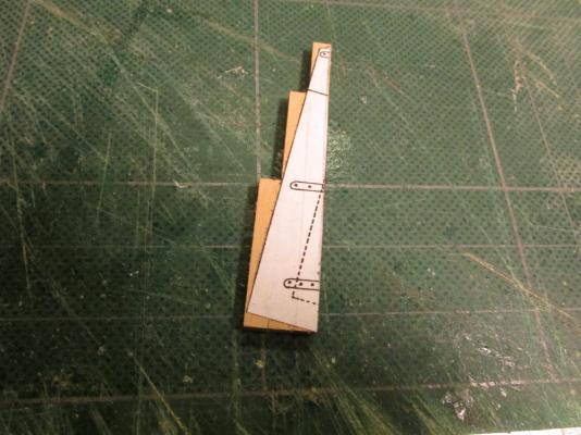
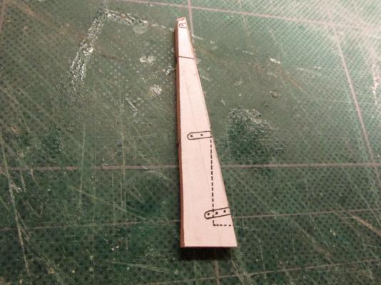
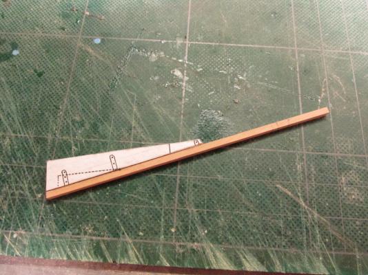
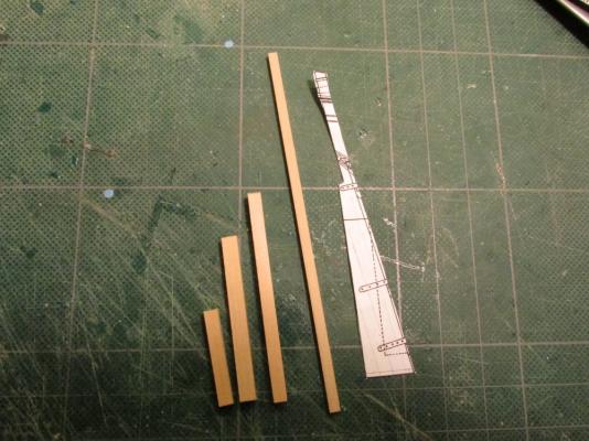
Rudder and Tiller It’s time I spent working on the other end of the ship and add the rudder and tiller. Per the Practicum, the rudder is made of three pieces: 2 boxwood pieces for the rudder and tiller, and 1 ebony piece (in my case black painted walnut) for the false keel extension. Based on what I have seen in this website and other sources, the rudder is not a solid piece wood. The Mamoli plans as well as the Model Shipway plans both show a composite build albeit slightly different from each other. Hahn’s plans do not address the makeup of the rudder. I chose to follow the Mamoli plan. The Practicum calls for the rudder post to be made of 1/8” square boxwood. Bob Hunt used a single piece of 1/8” boxwood, but because the wood package does not contain a piece of the rudder size, the Practicum instructs you make it from two pieces of 1/8” x ¼” edge glued to give sufficient width. If I have to edge glue two pieces, I might as well edge glue 3 piece of 1/16” x 1/8” to match the Mamoli plans. Since my wood package didn't have 1/16” x 1/8” boxwood, I used 1/16” x 5/32” and used my Byrnes dimension sander to reduce it down 1/8” thick. Hopefully I didn't use too much of the 1/16” x 5/32” boxwood for whatever it was later intended.
- 974 replies
-
- rattlesnake
- mamoli
-
(and 1 more)
Tagged with:
-
I'll throw in my 2 cents about tree nailing: Point one, ships used treenails. Point two, tree nails were not used as a fashion statement. Therefore on my Rattlesnake, I did nothing to enhance the contrast to make them stand out. I like to think of the model like an onion. As you peel back on layer there is another. So the closer you look, the more detail you see. The effect I believe, should subliminal. Why does one model look better than another. Many times you can't put your finger on it, but I think it boils downs to craftsmanship, presentation, and the little details. Treenails are the little details that you may not a first realize are there but enhance the overall effect. That said, I'm really a novice at this. The Rattlesnake is my first POB sailing ship so take this with a grain of salt.
-
Thanks. I'll be starting work on the rudder and tiller soon, probably next week. Not much construction will take place this week due to the Nautical Research Guild Conference in Charleston SC.
- 974 replies
-
- rattlesnake
- mamoli
-
(and 1 more)
Tagged with:
-
Based on the typical dimensions of a home toilet and the images provided by Pasi, I made the sides height 3/16” and the seat opening 1/8”. I was a little concerned that I might have trouble with the bumkins fitting right next to the seats, but I think I’m OK.
- 974 replies
-
- rattlesnake
- mamoli
-
(and 1 more)
Tagged with:
-
This was remedied by drilling and carving out a crude U-shaped opening. As long as it was a clear shot, as it were, to the sea it worked. This part of the structure would not be seen.
- 974 replies
-
- rattlesnake
- mamoli
-
(and 1 more)
Tagged with:
-
In addition, only a portion of the base is to be seen. Once the base was installed I realized I shaped it wrong – it covered too much. The area directly below the seat was not open enough.
- 974 replies
-
- rattlesnake
- mamoli
-
(and 1 more)
Tagged with:
-
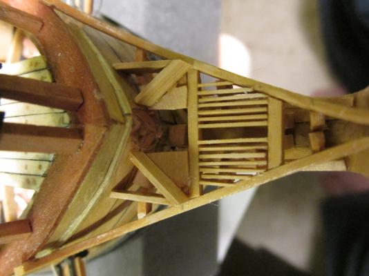
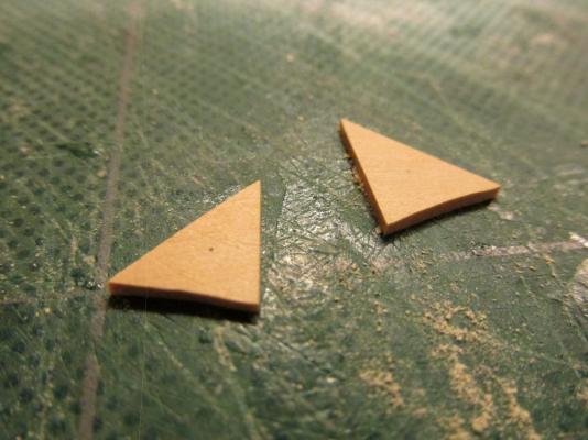
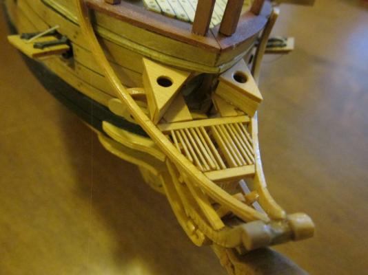
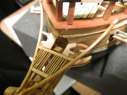
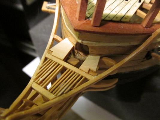
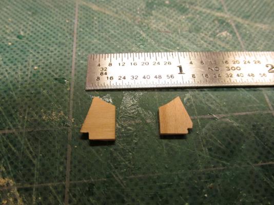
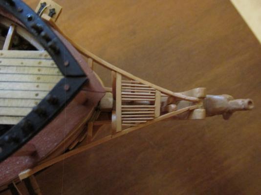
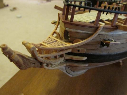
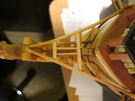
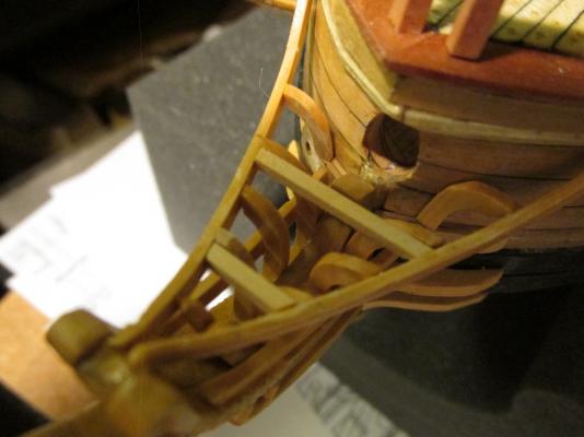
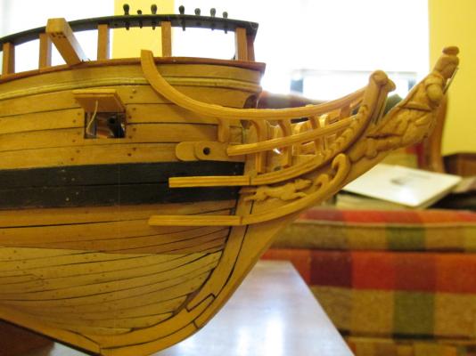
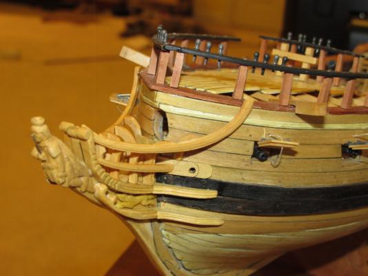
As I have mentioned before I am following fellow Rattlesnake builder Pasi Ahopelto. His seats of ease varied a bit from that shown in Hahn’s plans. Each seat is made of 4 pieces of boxwood, the base, 2 sides, and the seat. The base was the trickiest part because it had to fit flush with the grating and wrap around the cross beams and rail supports.
- 974 replies
-
- rattlesnake
- mamoli
-
(and 1 more)
Tagged with:
-
Yeah, I got lucky. I only found out about the Guild earlier this year and then it turns out they had a yearly conference and then to find that it was being held in my neck of the woods and I had the time (newly retired), the opportunity, and the money to attend...I hit the jackpot.
- 974 replies
-
- rattlesnake
- mamoli
-
(and 1 more)
Tagged with:
-
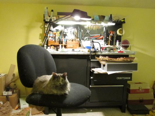
Peaches, my cat, is extremely affectionate. She will actually asked to be picked up and held ...tightly multiply times during the day. To get her off the chair and make it seem like her idea, I show her my secret weapon - a comb. She loves to be combed and combine that with a tummy rub, she will come running. Crazy for a cat, right? Once she has been sated, the chair is mine again. I hope to get the seats of ease done by this weekend. Next week I'll be attending the Nautical Research Guild Conference in Charleston SC which not too far from where I live. I hope to learn a bunch to stuff and have a good time. http://www.thenrg.org/2013-nrg-charleston-conference-details.php So things on the model building side may slow down again.
- 974 replies
-
- rattlesnake
- mamoli
-
(and 1 more)
Tagged with:
-
How did it work out with your lettering? Having never tried reversing the dry transfers with tape, how did you make the letters stick to the transom and not the tape when you rubbed the tape? Wouldn't the tape peel off the dry transfers when you removed it? Of all the build logs I've looked at for the Rattlesnake, yours is the first I've seen for the painting stage. Since my model isn't and won't be painted, I look forward to watching yours as you progress.
-
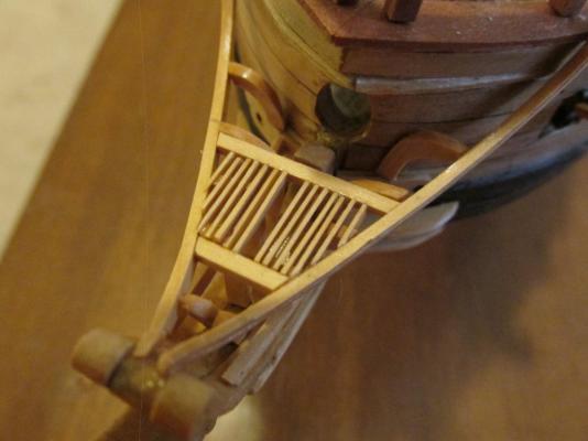
As the slats installation approached the rails, accommodations also had to made to custom fit each slat around the rail supports and rail angles. As each slat was placed into position, I waited at least 30 minutes before working next to it for the next slat less I touch it and knock it out of position. Work progressed very slowly. The results although not perfect in the close-up images, I believe will work. Next comes the seats of ease themselves.
- 974 replies
-
- rattlesnake
- mamoli
-
(and 1 more)
Tagged with:
-
It appeared that Pasi used Hahn’s plans only as a guide in that he made his slats the same width as the cross timber. I chose to make mine narrower. Even the Hahn plans were not drawn very consistently as to their width. As the installation progressed, it became obvious that this was not going to be easy. Working with an eye loupe on my glasses (I wear tri-focals), trying to hold the model at a steady and proper work angle while maneuvering the delicate slats into precise position, with proper lighting so I could see what I was doing, before the CA glue dried, proved to be a challenge. Oh did I mention that I had to fight to get my work stool from my cat? I mean how can anyone disturb a contented cat?
- 974 replies
-
- rattlesnake
- mamoli
-
(and 1 more)
Tagged with:
-
Then the first of fourteen 1/64” x 1/16” grating slats were installed starting from the center. Following Pasi’s photos, I left a wide space in the center to separate the two gratings.
- 974 replies
-
- rattlesnake
- mamoli
-
(and 1 more)
Tagged with:
-
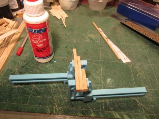
I couldn't follow Pasi’s build exactly as he built his model because he was working to a larger scale: ¼” – 1’. In particular, he used lap joints for his grating which I was not able to duplicate at my smaller scale. I therefore used butt joints because cutting clean, equally spaced, notches in the cross timbers either completely across or half way for lap joints was beyond my ability and it would not be noticed to the casual observer without a magnifying glass. First, the cross beams made of 1/16” square boxwood were cut to size, fitted, and installed.
- 974 replies
-
- rattlesnake
- mamoli
-
(and 1 more)
Tagged with:
-
As you can tell from my log, I haven't started the masts or yards. In fact I have never made any masts or yards before. I hope you will create your own build log so I can learn from you by following your build and photos.
- 974 replies
-
- rattlesnake
- mamoli
-
(and 1 more)
Tagged with:
-
Welcome aboard! I hope my experiences in building this model helps you to build yours even better than mine. As you may of read early in my build log, this is my first build of this type, so I hope you will forgive any errors I have made along the way. Good luck to you.
- 974 replies
-
- rattlesnake
- mamoli
-
(and 1 more)
Tagged with:
-
I'll be away from building anything this weekend so the earliest you will something will be at least a week away. For the notches, I think, due to the scale, butt joints would work for you. I'm thinking of using 1/32" x 1/16" boxwood (which I will have to mill myself) for the grating and will either notch completely across the cross beam or butt joint. Remember, Pasi was working to 1/4": 1' scale so he had the luxury of larger scale and therefore more space. The seat of ease does have a place for the user's feet. Using the seat, the sailor is facing inward towards the center-line and Pasi did provide a flat surface there. It should be interesting to see how this turns out. What are the "sister blocks" you referred to? Take care Jon
- 974 replies
-
- rattlesnake
- mamoli
-
(and 1 more)
Tagged with:
-
The next step is the construction of the grating and “seat of ease” otherwise known as the “head.” Again, for some reason (I suspect Mr. Hunt was running out time to publish the Practicum and he was building four boats at once), the Practicum is totally silence on its construction. For guidance in this phase, I will fall back to fellow Rattlesnake builder, Pasi Ahopelto’s wonderful but now unavailable build log. Luckily I made a copy of it for reference while he was posting.
- 974 replies
-
- rattlesnake
- mamoli
-
(and 1 more)
Tagged with:
-
- 974 replies
-
- rattlesnake
- mamoli
-
(and 1 more)
Tagged with:
About us
Modelshipworld - Advancing Ship Modeling through Research
SSL Secured
Your security is important for us so this Website is SSL-Secured
NRG Mailing Address
Nautical Research Guild
237 South Lincoln Street
Westmont IL, 60559-1917
Model Ship World ® and the MSW logo are Registered Trademarks, and belong to the Nautical Research Guild (United States Patent and Trademark Office: No. 6,929,264 & No. 6,929,274, registered Dec. 20, 2022)
Helpful Links
About the NRG
If you enjoy building ship models that are historically accurate as well as beautiful, then The Nautical Research Guild (NRG) is just right for you.
The Guild is a non-profit educational organization whose mission is to “Advance Ship Modeling Through Research”. We provide support to our members in their efforts to raise the quality of their model ships.
The Nautical Research Guild has published our world-renowned quarterly magazine, The Nautical Research Journal, since 1955. The pages of the Journal are full of articles by accomplished ship modelers who show you how they create those exquisite details on their models, and by maritime historians who show you the correct details to build. The Journal is available in both print and digital editions. Go to the NRG web site (www.thenrg.org) to download a complimentary digital copy of the Journal. The NRG also publishes plan sets, books and compilations of back issues of the Journal and the former Ships in Scale and Model Ship Builder magazines.


