Check out our new MSW Sponsor Innocraftsman
×


JSGerson
-
Posts
2,603 -
Joined
-
Last visited
Content Type
Profiles
Forums
Gallery
Events
Everything posted by JSGerson
-
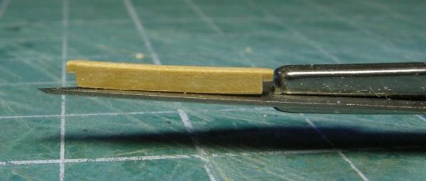
 Head Rails According to the Practicum, I've come to “one of the most difficult areas of the ship model.” Don’t you just love that kind of encouragement? The first things to make are the cheek rails, a set of upper and lower rails starting from the wale area and working their way onto the stem. They are made in two parts: the wale component and the stem component. The first template was made for the top wale components from the Hahn plans, rubber cemented to 3/32” x ¼” boxwood, and cut out with the scroll saw. These pieces have a molding on their edge. Mr. Hunt stated that he used a #10 Exacto blade to form them. I don’t know how he did carve them that way. I used the razor blade method as I did on the other moldings. Let me tell you, cutting the razor blade was easy; cutting the razor blade with precision was not. I used an X-Y table on my Dremel “drill press” with the cutting discs attached to the Dremel held horizontal and the razor blade mounted vertical. I then could move the razor blade precisely. My first molding attempt worked but I was not satisfied. I made three grooves in the wood instead of two as shown and felt they didn't stand out very well. My second attempt was a disaster. Because the wale cheek has a wavy surface, drawing it across the razor blade was difficult especially because the piece was so small. Normally when making a molding, you work with a long straight strip and you a pulling with the grain of the wood. With the cheeks the pieces are very short and the grain changes due to the curvy shape of the wood. The stem component was supposed to be made from 1/8” x ½” boxwood but since the wood package did not come with this size, Mr. Hunt stated in the Practicum to glue two piece of 1/8” x ¼” to make it. I found this to be unsatisfactory. The stem cheek rails are slender and they will have to be carved not only with a molding but a design as well. I was afraid that in the process of hand carving the pieces, I could break the fragile glue joints. Therefore I ordered a 1/8” x ½” boxwood package from HobbyMill which consisted of two 24” pieces. I should have plenty of wood in about a week’s time should I screw up. Basically I accomplished nothing this week. To make matters worse I wanted to try using cutter bits (like what the dentist uses) but I've misplaced mine and wasted a bunch of time looking for them. No luck so far. Then the video card on my computer died. I was able to cannibalize an old card from a dead computer but now the image stretches to fill the 9x16 aspect ratio screen. Sometimes it just doesn't pay to get out of bed.
 -
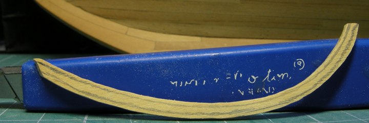
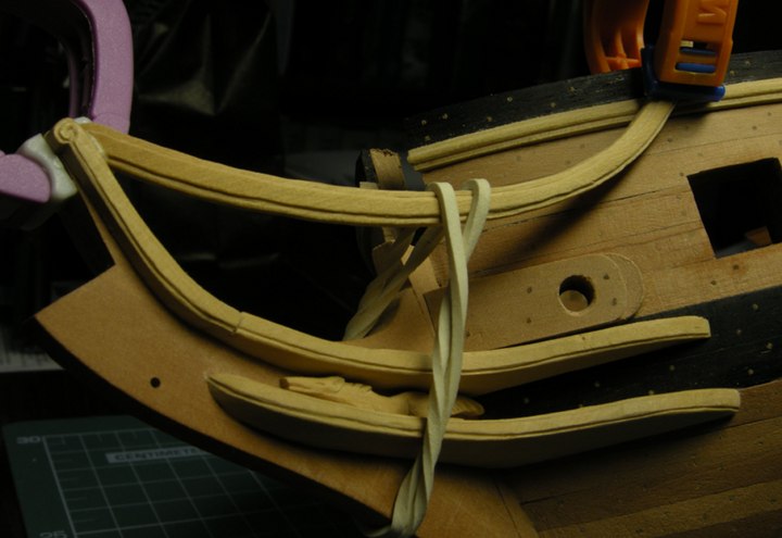
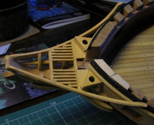
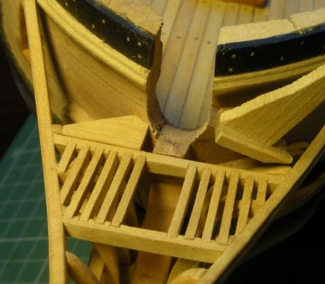
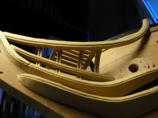
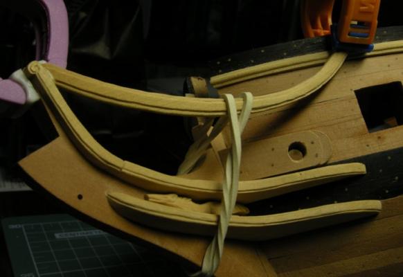
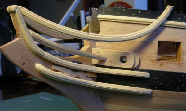
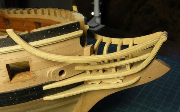
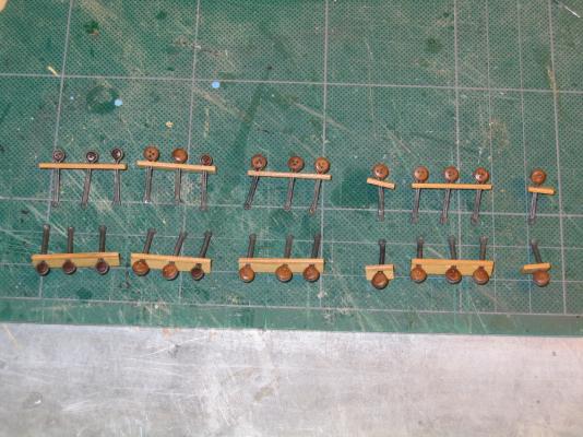
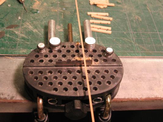
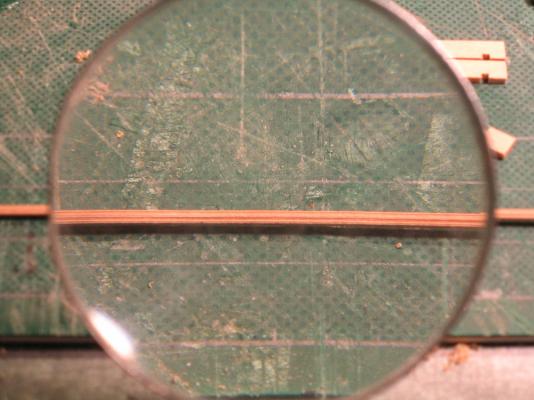
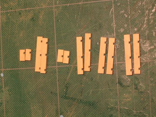
Found a few more. Sorry there not in order. I hope these help. And thank you Pasi Ahopelto

- 974 replies
-
- 1
-

-
- rattlesnake
- mamoli
- (and 1 more)
-
A few more images

-
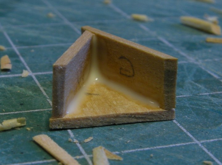
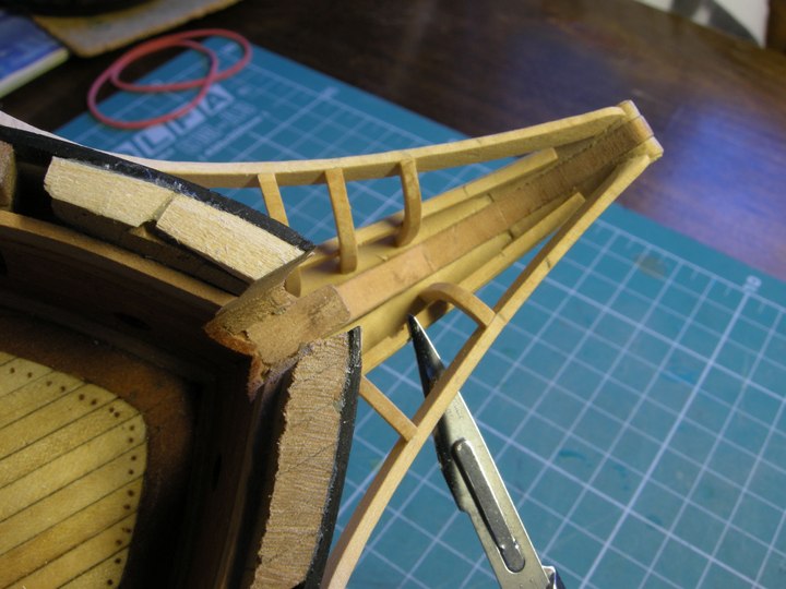
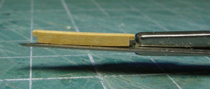
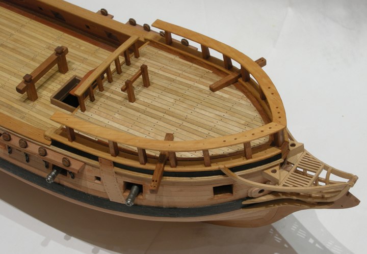
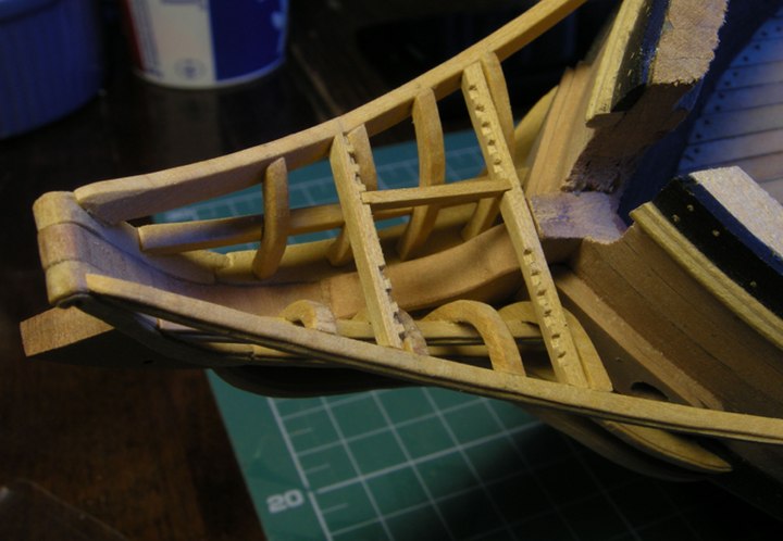
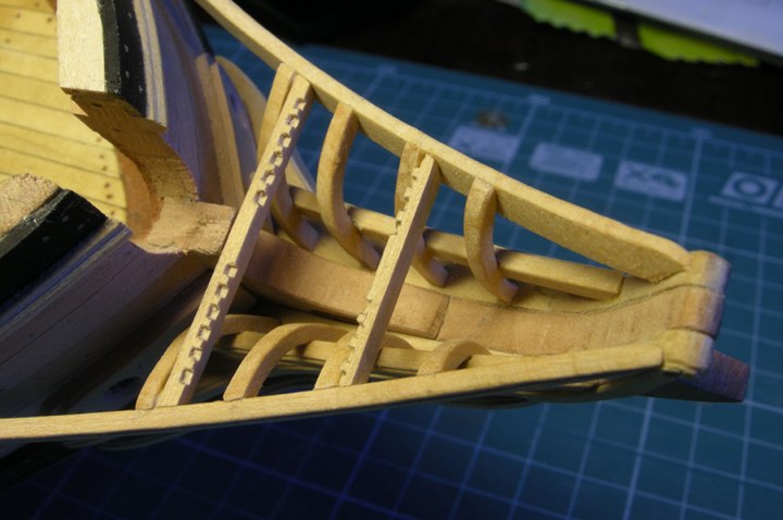
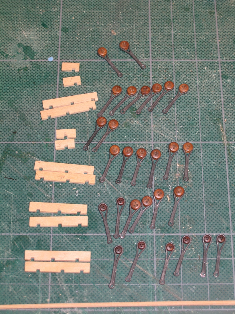
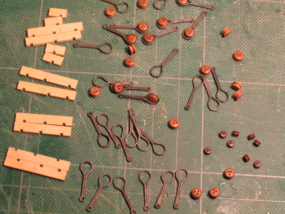
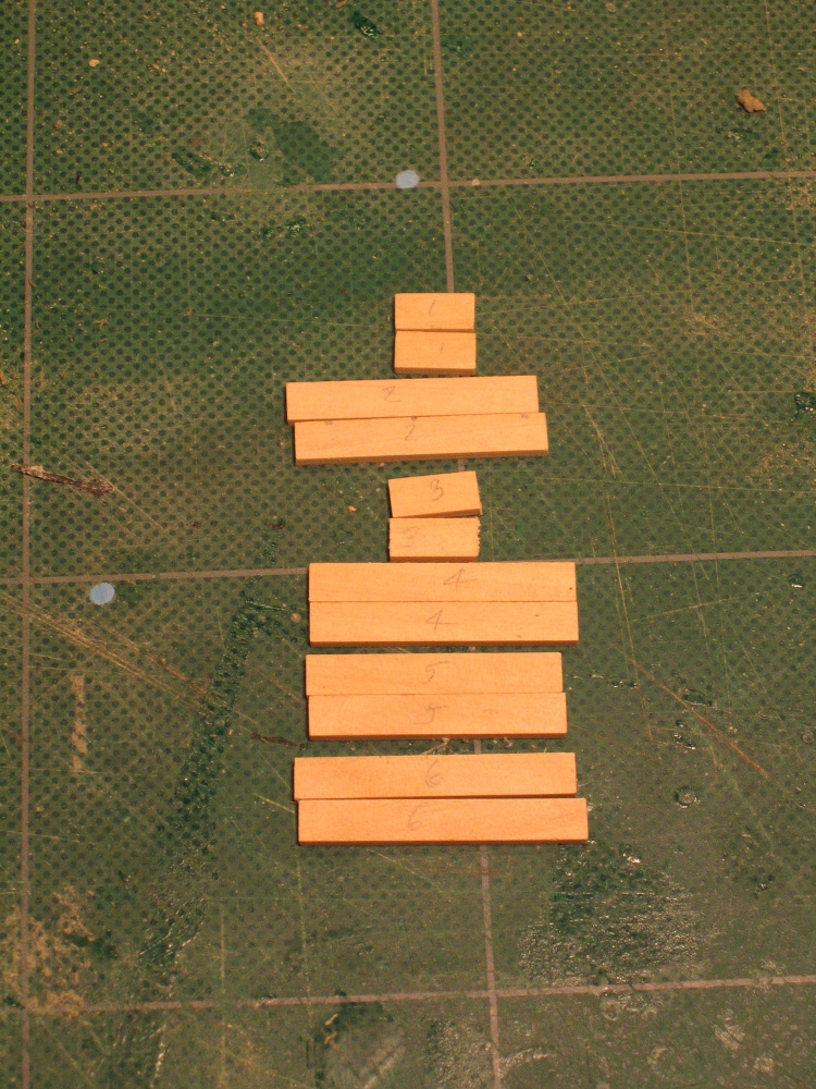
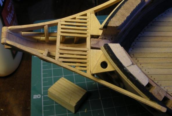
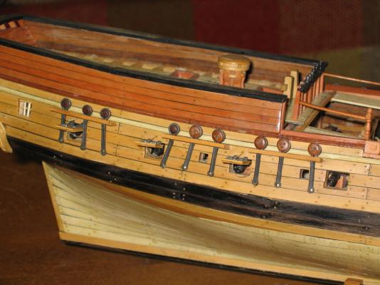
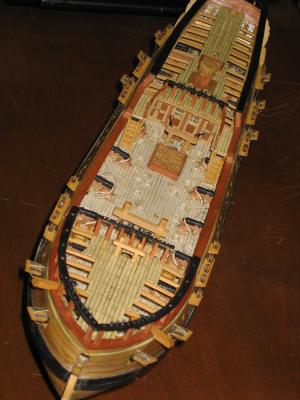
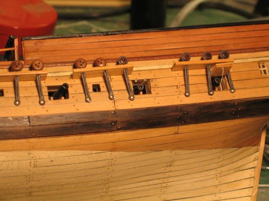
Thanks for the, ahem, encouragement. I have some images from Model Ship World 1.0 when Pasi Ahopelto had a running build log. He was following the Hahn's plans directly so his model was 1/4" = 1'. It was a wonderful log and a beautiful build but unfortunately when MSW 1.0 died, so did his build log. I however, in my infinite wisdom, had copied all of his images before this happened. Here for your use are his images on how he built the head rails.


-
How "neat a solution" it was will depend how long those lids will remain attached before I, like you, knock them off. They were a minor pain to attach. I am starting the head boards and that will require a lot of manipulation of the model as I manufacture, fit and install all of those little parts. Wish me luck!
-
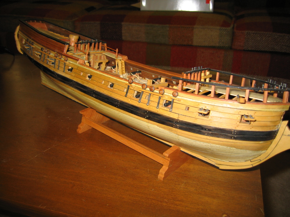
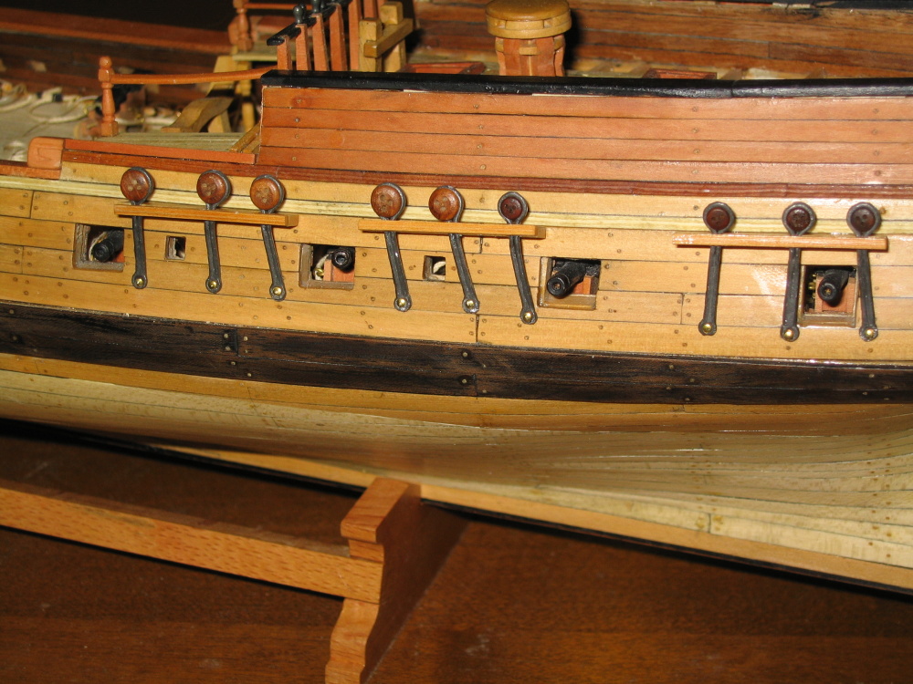
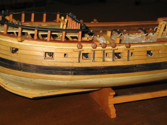
Then there is the matter of gun port lid tackle used to open and close the lid. The Practicum and Hahn’s drawings are silent in this regard. The Mamoli plan’s show a continuous rope from the inner hull through a hole just above the gunport and below the channels through a hole low in the lid which then hangs down inside the hull. I must assume there were knots or some other method by which the rope was secured to the lid on the actual ship. These would be too small to see at this scale. The Model Shipway plans (which I just got my hands on) show a ring on the outside of the gunport lid from which the rope is attached and then goes over the channels into the hull. Going over the channel doesn’t make sense as the rope would then be passing through the hull and appearing on the deck above. Nothing is shown as to how the lid was closed. Any ring that I could buy or fabricate would appear to my eyes too large for the scale of the model. Based on the above, I have elected to follow the Mamoli plans. The method of securing the rope to the lid is moot as far as I am concerned due to the scale. In actuality, beige thread was glued to a hole on the outside hull above the gunport and below the channel, passed through a hole in the lid at the lower end and glued to the inside hull as if it were secured by a cleat which the observer can’t see. To accomplish this, the thread was first glued to the outside hull above the gunport. Once set, it was threaded through the hole in the lid. The model was laid on its side and the lid was CA glued in place so it stood vertical. It was almost like balancing a pencil on its end. It was left this way for at least 30 minutes. I was taking no chances. This was done nine more times. This took a lot longer than I had expected. The result is shown below.


- 974 replies
-
- 2
-
-
- rattlesnake
- mamoli
- (and 1 more)
-
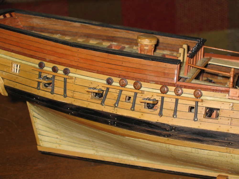
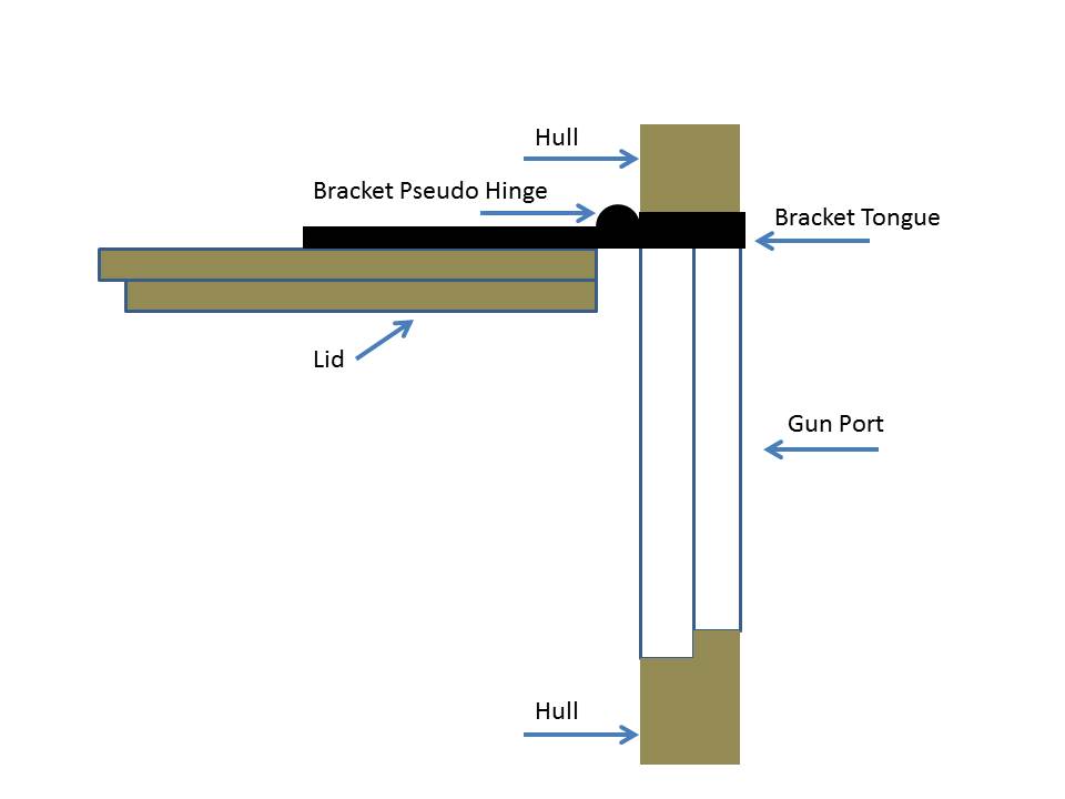
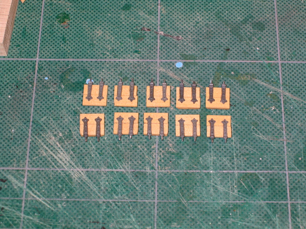
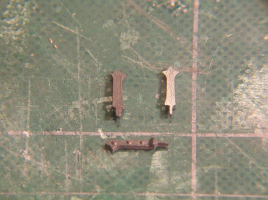
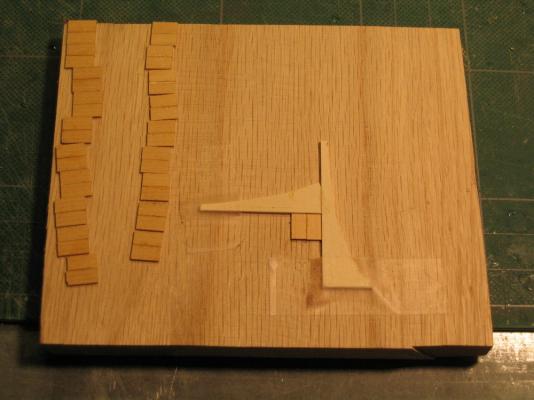
The practicum only stated that the lids were attached in an open position with no detail. It appears from the pictures provided that Mr. Hunt simply cut off the tongue from the bracket and just glued the lid edge directly to the hull. If one wants the look of hinges, then the use of the tongues is a must. The tongues on the brackets are rectangular in shape and cross section. Because the pseudo hinge had to appear at the gun port opening edge, a simple drilled hole would not work. The drill would not stay in place; grooves would have to be formed for the bracket tongues. I used a variable speed cordless rotary tool with a cone cutting bit. The picture below shows the three stage: Before, drilled holes, completed installation. The center gunport shows the grooves in the top of opening that is for the bracket tongues.
-
The brackets were then glued to the lids with the pseudo hinge off the lid otherwise the lid would not be able to swing if the hinge were actually real.


-
Each door required two brackets. At the top end of the bracket was a pseudo hinge and gluing tongue. The practicum was correct in stating that the kit’s brackets were a bit thick. Rubbing the back of the bracket on a fine sanding block, material was removed leaving a smooth shiny surface from what was a slightly rough and concave finish. Additionally excess metal was also trimmed away.
-
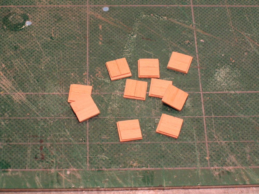
To create the actual lid, an outer component and inner component were glued together at right angles to each other with one edge flush with each other in such a way that outer component slats were horizontal.

-
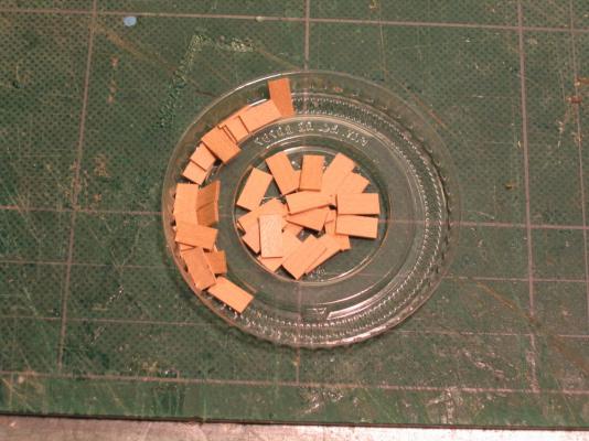
20 pieces were cut to a length of 3/8” and another 20 were cut 1/32” shorter. Although you can’t tell in the picture above, the inner pile of pieces is the large size. This was a modification of the method described in the Practicum which used 40 pieces cut to the same length but required subsequent hand trimming. I thought my method was simpler and it gave the same final results. Two pieces of the same size were glued along their long edges using a simple jig to ensure everything was square making a component. The larger ones made the outer component and the smaller the inner.
-
The Gunport Lids Although the Rattlesnake is a 20 gun ship only 10 of the gunports, which are under the Quarter Deck and the Forecastle, have lids. In lieu of using the kit supplied one piece lid these are fabricated from 4 strips of 1/32” x 3/16” boxwood. Two of the strips glued at their edges are perpendicular to the other two strips glued the same way. The one difference is that the inner side of the lid is has a 1/32” lip on the sides and bottom.
-
There are so many great build logs on MSW it's hard to keep track of them all. Thanks for pointing me to Blue Ensign's blog. It's getting so I haven't had any time to build, I spend so much time reading everybody's else's stuff. I'm about halfway through making the gunport doors and will post them as so as I'm done.
-
Flattery will get you everywhere! Careful, I may sound like I know what I am doing but I'm learning on the fly. There are a lot of things I wish I could do over and hopefully better. For example, I'm still not comfortable with planking. Looking at other builds and can see that I have a lot to learn. The part that really scares me are the masts and yards not to mention the rigging. But like they say, take it one step at a time...that and a deep breath!
-
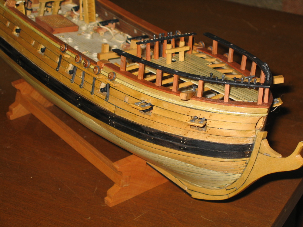
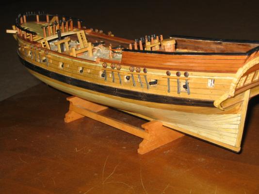
Now it was just a matter of positioning the channels and chain plates according to Hahn’s plans and gluing and fastening everything down. The results you see below.

- 974 replies
-
- 1
-
-
- rattlesnake
- mamoli
- (and 1 more)
-
I received a tip from Martin W for a simple way to shorten the chainplates, but in the end I decided it really didn’t make much difference; the amount was so small. If one were follow exactly the Practicum and glue the molding to the channels before slipping the chainplate into the resulting square hole, you would quickly realize that the chainplate won’t fit. The loop at the bottom where the nail is to go is twice as large as the opening. Of course if I followed Mr. Martin W’s tip of snipping off the loop and drilling a new hole there would be no problem. So instead I cut the moldings to length and glued them on with the chainplates in place.
-
I have the Byrnes Thickness Sander and as usual it is up to his high standards. The only items I don't have are his new rope walk and and the disk sander. They're on the expensive side but you get what you pay for.
-
Not a bad idea. Since I'm still attaching them to the channels and they are not on the model I can still do that. Thanks for the tip.
-
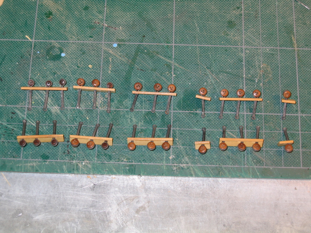
The chainplates are made of Britannia metal which very soft and has the consistency of lead (without the lead). It is very easy to break. So very carefully the large loop of the chainplate was squeezed tight as much as I dared around each deadeye, eight of which were of a smaller diameter. The Practicum discusses how Mr. Hunt modified the kit’s chainplates to shorten them, but I didn't want to risk doing that. The channel moldings were made in the same fashion as my earlier moldings using a razor blade with the molding cross section cut into it. The wood strip was then drawn repeatedly over the cut area until the design was cut into the wood.

-
At this point the Practicum gives the builder a choice to either use the kit supplied chainplates or make their own. Based on the experience of Mr. Hunt and the need to solder very fine pieces, I chose to follow his lead and use the kit provided chainplates. They look a bit different from the Hahn’s plans, but it’ll work. Here an image of all the components necessary to create the channels.

-
CHAPTER 9 - Final Details The Channels Basically the decks are complete sans the rigging accoutrements; it’s time to work on the channels. The first thing I noticed was that the Practicum directs the construction of 6 channels per side. Looking at the Hahn’s plans, it shows only 5 (two in the bow and three at the aft end) while the Mamoli plans shows 6 (3 at each end). The channel in contention is the one which starts from the edge of the forecastle. As a two channel breaking over the gun port configuration, the first channel contains one deadeye and the second contains three. As a single channel, it contains all 4 deadeyes and spans over the gun port. To get a consensus of which way I should build them, I went looking at my collection of 44 different Rattlesnake models images (Mamoli, Model Shipway, scratch built and pre-assembled). Only two model-makers built their models with 5 channels (a very fine Hahn’s based POF and a pre-assembled), so it would appear the 6 channel configuration is the model of choice. So be it. Using 1/16” x 3/16” boxwood two pieces each of six lengths were cut per the Practicum. These were then placed on the drawing to determine where the 1/16” notch for the chainplates were located. As shown in the Practicum, I used the Byrnes saw with a .40” thick blade to cut a 1/16” notch. The Practicum called for a .057 thick blade, but I didn't have one. A fine diamond coated needle file will be used to get the extra width.

-
If you take a look at the Mamoli plan sheet No. 3, in the center right of the illustrations, it is part No. 107. On the Model Shipways plan (yes I finally received them) identified in the bottom right hand corner as "Plan-on Bulkhead Hull Construction" look at "section C-C" in the center of the drawing. The Hahn's plans don't address them. Somewhere I read that the gang planks were removed while out to sea, but those supports are something I wouldn't want run into during battle or in a storm.
-
I'm curious, when the sailors removed the temporary gangplanks, what happened to the supports that held them up? They look like metal right angle brackets mounted directly to the bulwarks. If they are left in place, wouldn't that be some sort of work hazard? I know they didn't have OSHA looking over their shoulders but those shipwrights did know how to build a ship! In other words, should I install the brackets without the gangplanks?
-
From what I understand, the temporary gangplanks were removed while the ship was at sea. The Practicum, based on Hahn's plans, does not address these. Some of the models I have images of show the temporary gangplank and some do not so at this point I have no plans to add them. If I did, I would have to move the ladders. They would also cover up the remaining cannon from view. Also some of the models show netting by the gangplanks. I'm not sure if that is part of the gangplanks or not so I'm not sure yet if I will try to make that.
-
It was all done with fine needle files (flat and V-shape) and a very fine chisel