JSGerson
-
Posts
2,646 -
Joined
-
Last visited
Content Type
Profiles
Forums
Gallery
Events
Everything posted by JSGerson
-
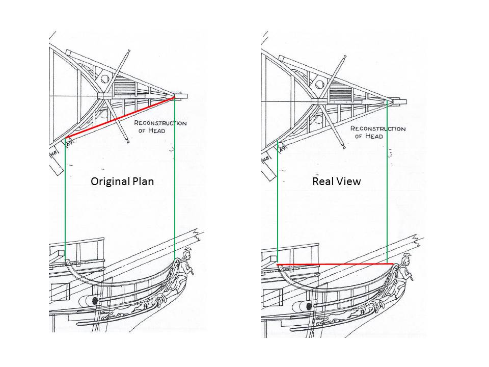
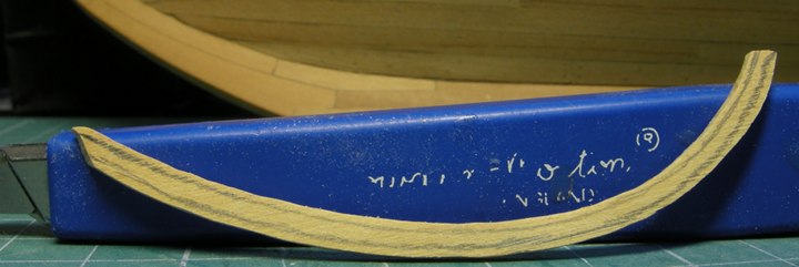
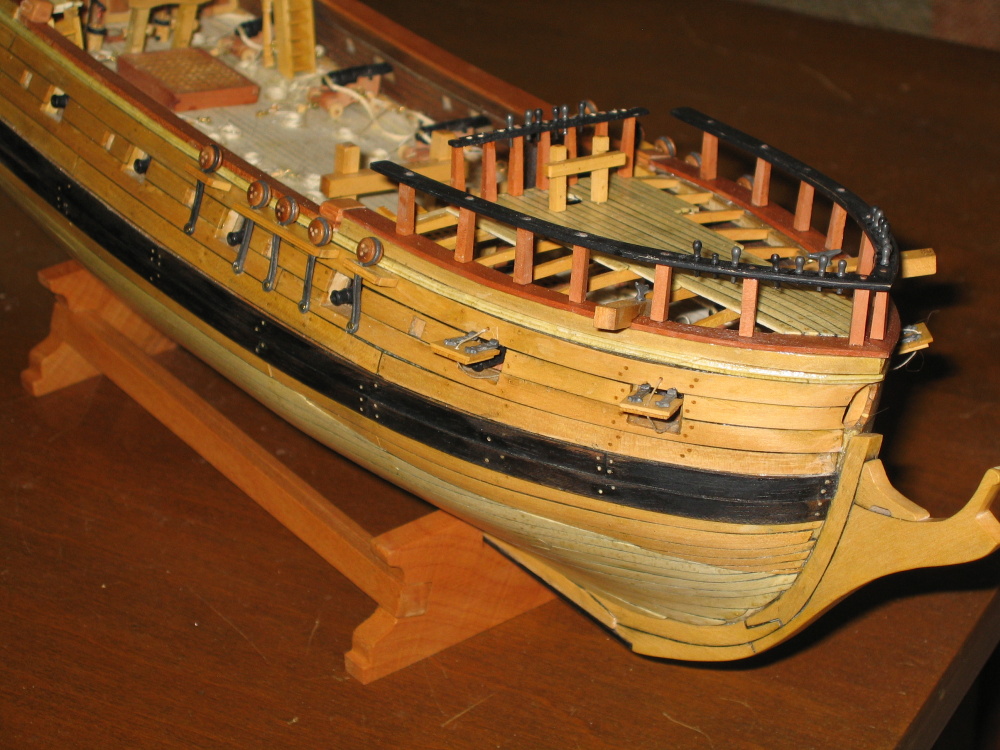
 Back to the Head Rails When viewed from the side, the head rail forms a sweeping arc from the bow to the tip of the stem. From the top it is straight and tapers toward the stem. None of the plans from Harold Hahn, Mamoli, or Model Shipways shows the head’s true full scale shape. All of them either show a top down view or an elevation (side) view. The rail is foreshortened in the elevation view. The Practicum tries to address this by having you reduce Mr. Hahn’s plan 90% instead of the 72% or 75% as before in order to increase the size so the template would properly fit. My 3 in 1 home copier/scanner/printer cannot do reductions or enlargements so that option was out. Even if I could, I wouldn't do it this way. Yes, you may get the proper length, but now the height would be larger as well. While I was still employed (up until this time last year) and still had access to my company’s copier, I made a number of piece-meal legal size copies of the reduced version of Han’s plans so that I could cut them up to make templates without ruining the original reduction version. Using one of those copies I scanned the bow section into the computer. On the scanned image I drew a line (red) on the rail in the top view. This was the true length of the rail. This line was copied, rotated till it was horizontal and placed on a second copy of the scanned image. The second scanned image was then stretched horizontally until the elevated view length of the rail matched the horizontal red line. Now I had a true length of the rail without any vertical distortion to be used as a template. You can see how much longer the rail is when compared to the green reference lines.
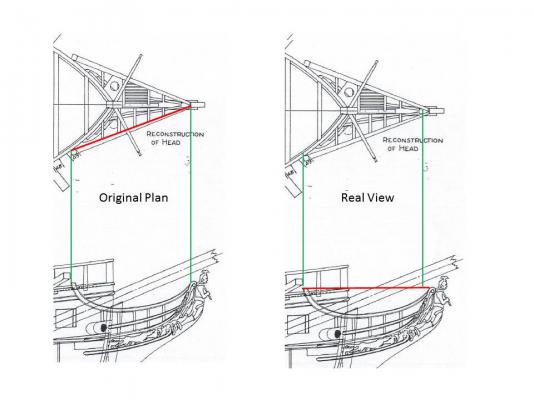
-
In pre-computer days, I made a lot of forms for use in my office, I drew every line by hand and lettered all the text with dry-transfers (rub-on). Multiple copies were then made on the Xerox machine. I know from experience how difficult it can be to get the proper kerning (spacing between lettering), letter angles, as well as proper line justification on nice flat smooth paper. To do this on a wood surface, in a cramped space that curve, on a model boat to boot, is no easy task. My hat is off to you. In my case, I think I might try making a decal. Because I included two molding strips that go across the transom, the lettering would have to go in between them. Applying dry transfers here would be very difficult if not impossible. First I would plan to print the name on a piece of paper to check for size, placement, font selection, etc. and then create the decal. The results are yet to be determined.
-
I don't mind a bit, in fact I encourage it. I may be working on a tricky part now, the head rails, but as I think I mentioned before, I am very apprehensive when it comes time to work on the masts, yards, and rigging. So I am following a lot of people, including you Martin, on this part of the model construction. I have the luxury of time being unemployed/retired (depending whom I'm talking to) to work pursue my hobby more than an hour a day. So take your time Martin just so long as you document it, so I can learn from it. 8-) Jon
-
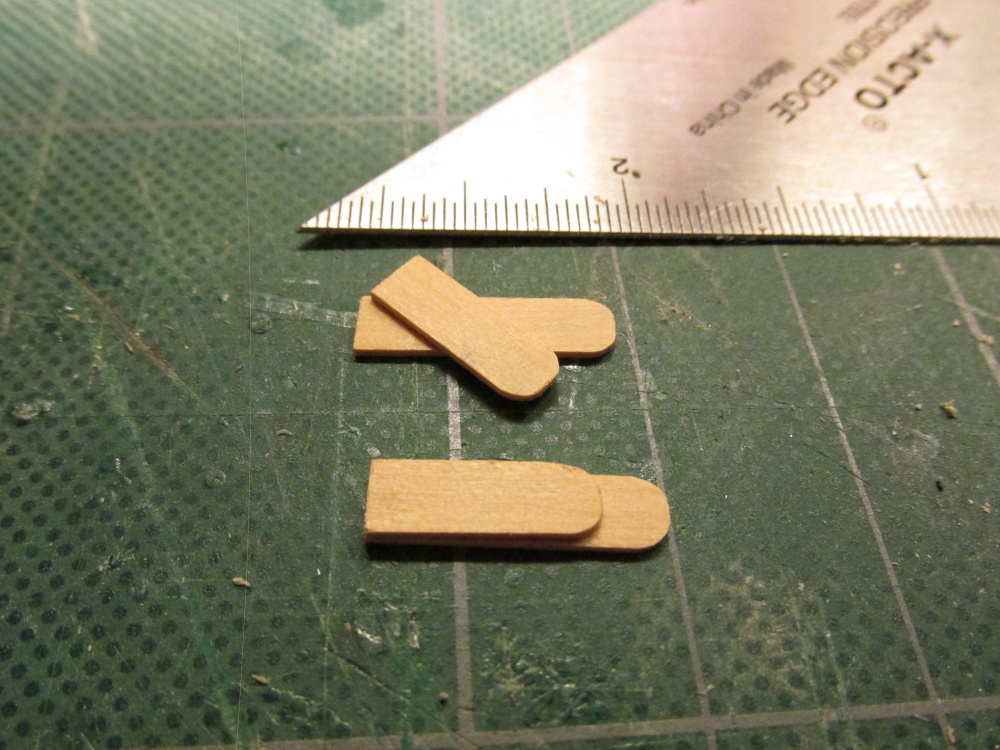
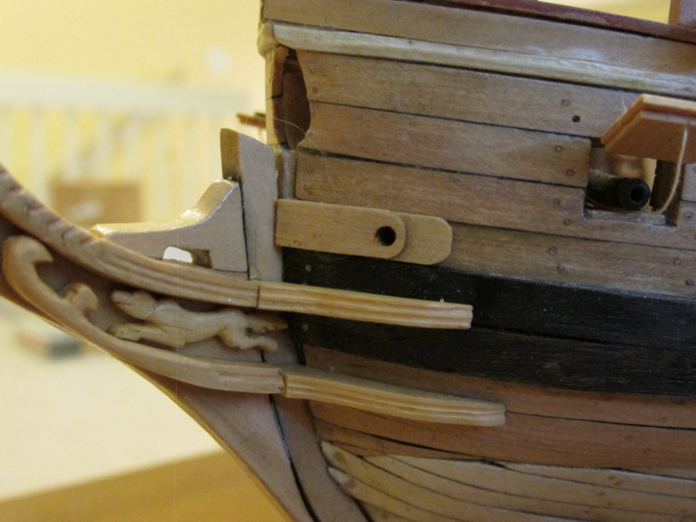
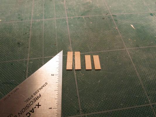
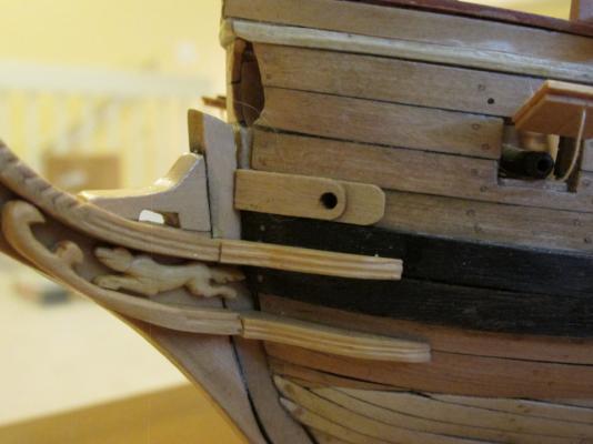
Hawse Port Reinforcement Boards This is a real simple item to construct. Using the last of my wood package’s 1/32” x 3/16” boxwood (I hope I don’t need anymore) two pieces were cut to size per side. One end of each piece was “rounded” and dry fitted for any alignments. They were then glued one on top of the other directly above the wale and against the stem. A 3/32” hole was drilled right through the hull and bulwarks near the outer end of the shorter board piece. A coat of Poly-wipe was then applied.

-
I did a quick search on the internet and although you can get vinyl lettering down to 2 or 3mm choices of font and color are limited. Ill be curious to see how you do.
-
Now that you mention it, I've got the same lettering problem myself. On my previous boat the Evergreen, I made my nameplate using a homemade decal.. By typing the name of the boat in whatever style/font and color I wanted (except white, you can't print white) on the computer, I could then print it in full scale size on decal paper which I got at my local hobby shop. Then I applied the decal coating (usually from a spray can) and let dry. It was then applied like you would any decal. But if you wanted raised lettering, that's a boat of a different color. One modeler I read about somewhere used vinyl lettering (as opposed to rub-on).Due to the scale, the letters appeared raised. The first trick is to find the right style/font, size, and color. The second, is the task of applying to the model with precision otherwise it will look awful.
-
Flattery will get you everywhere! Jon
-
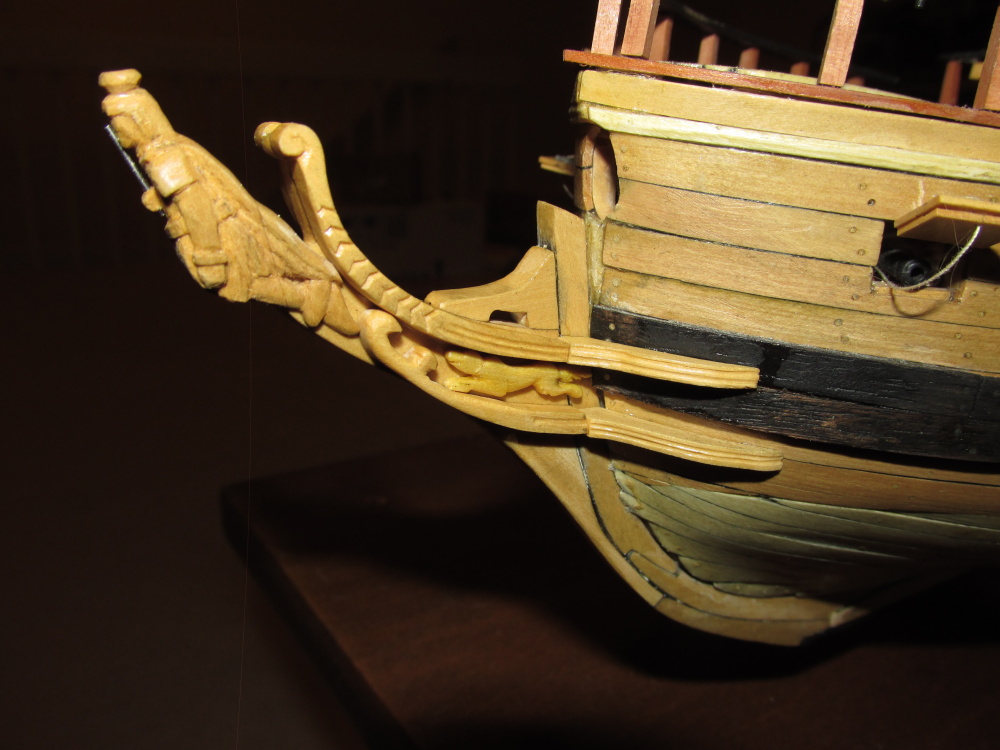
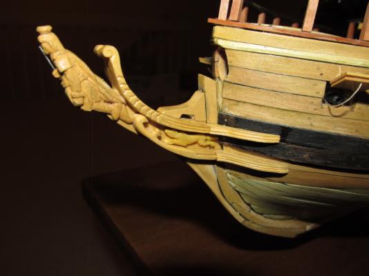
If you look closely at Hahn's plan, you can see remnants of the carving design on the lower cheek (I couldn't on the upper). What I interpreted was some of the same carvings that were on the transom hence my "fancy" carving. My apologies for calling the fox a wolf. Who could tell from my carving? I could have called it a dog!
-
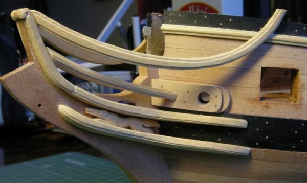
The two pieces that made up the lower cheek were constructed in the same manner as the upper cheek except the carving on the stem piece was different. In addition the wolf carvings and the masthead, made at the time the transom carving was done, were installed as well.
-
Thank you for the response. I will certainly look into get my hands on the book. I look forward to your photos. Jon
-
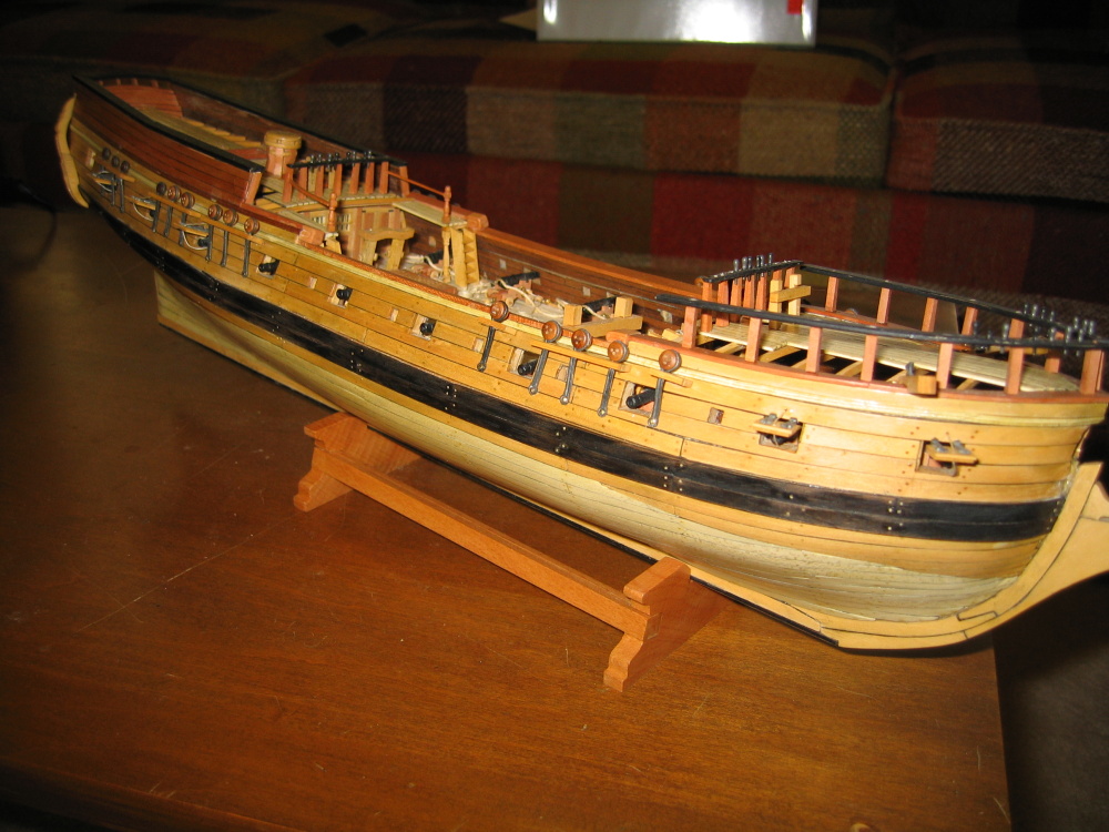
It's easy when you're a life long bachelor, forced into retirement (I got laid off just as I turned 66. I had planned to work till I was 67), no commitments, no dependents ( if you don't count the cat), and all the time in the world to do what ever. Actually I only put in a few hours a day, sometimes none, and others I just contemplating the sequence of actions needed to perform a particular task with no actual physical work done. Some might call that day dreaming! I've accomplished more in the last 12 months due to the "retirement" than I did in the four years prior. Yeah, I've been at it about 5 years. Looking at what needs to be accomplished for the masts, yards, and rigging I'm guessing another 2 years and that no including finishing the hull. At the rate I'm going, I figure I've got one more boat in me to complete and that's the Conny. After that I'll probably be half blind, feeble, no patience, and yelling at kids "get off the lawn."
- 974 replies
-
- 1
-

-
- rattlesnake
- mamoli
- (and 1 more)
-
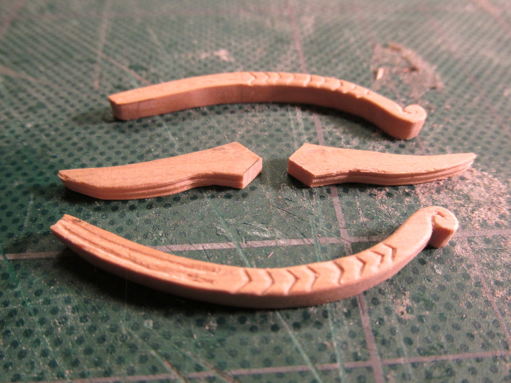
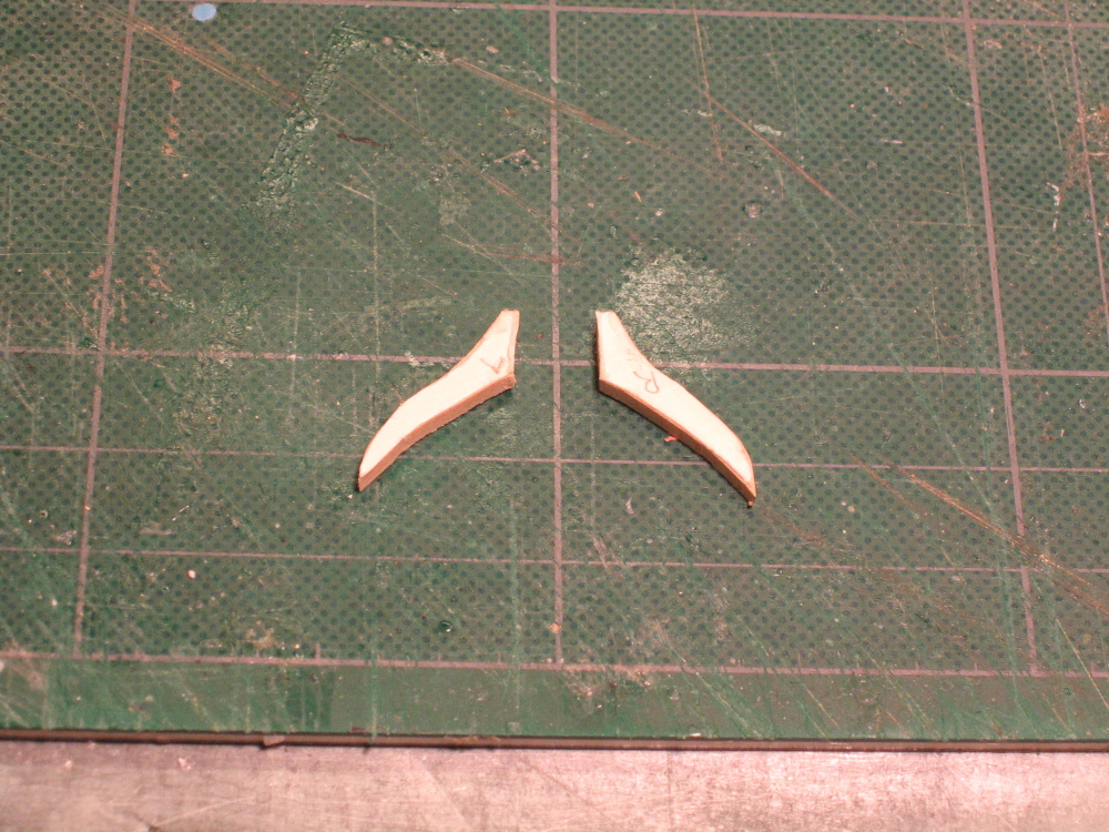
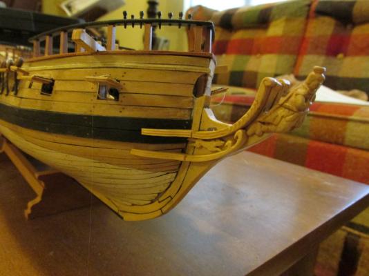
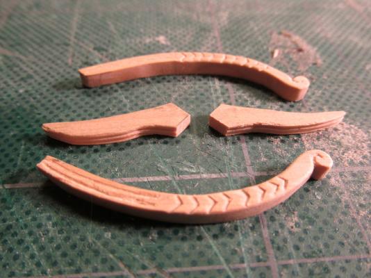
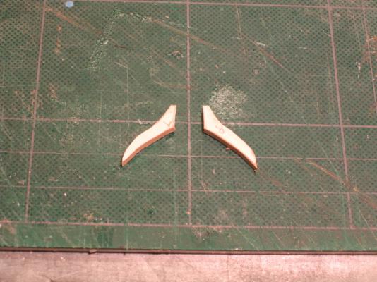
The upper stem cheek was fabricated the same way as the wale cheek using a card stock template rubber cemented to the 1/8” x ½” boxwood I purchased from HobbyMill. Using my “router” setup, two grooves were cut about 1/3 the length of the lower portion of the cheek so as to continue the grooves on the stem cheek. Most of the remaining area was carved with a chevron design as shown by the Practicum. The Hahn plans don’t show a good image of what it really is supposed to look like. The tip of the stem cheek is formed into a scroll to match the stem shape.
-
I am getting to the point soon were I will be building my Mamoli Rattlesnake longboat for my model. Although I am following Bob Hunt's Practicum as my "bible" as this is my first plank on bulkhead boat in 30 years. I never did finish that one. I plan to deviate from the Practicum and not use the boat shell provided in the kit. I purchased the Model Shipways 108mm boat kit MS0107. It just seemed like fun thing to do. I am not all that familiar with the "methods advocated by the late Ewart Freeston in his book Model Open Boats " or "W E May's book The Boats of Men-of-War ." What kit manufacture did you use? Did you use the boat supplied by the kit, or did you scratch build? The Mamoli's boat is a rough carved shell. I don't know what Model Shipways supplied, but suspect layers to be glued together like the kit I purchased. What has me a bit confused is that you stated "The plans of the Rattlesnake show a correctly proportioned longboat, but the lifts do not give the same result and there’s absolutely nothing that can be done to rectify the errors. The hull is too narrow, particularly towards the stern, and she lacks sufficient body for a longboat." If the kit plans were correct, where you stating that the boat parts were not? Anything that you can guide me along would be greatly appreciated
-
Glad to have shared the idea. The only other tiny shapes I have are the cone and tapered cylinder. Now if I can only find actual itty bitty router bits to do corners and fancy edges, we could really do some fancy stuff!
-
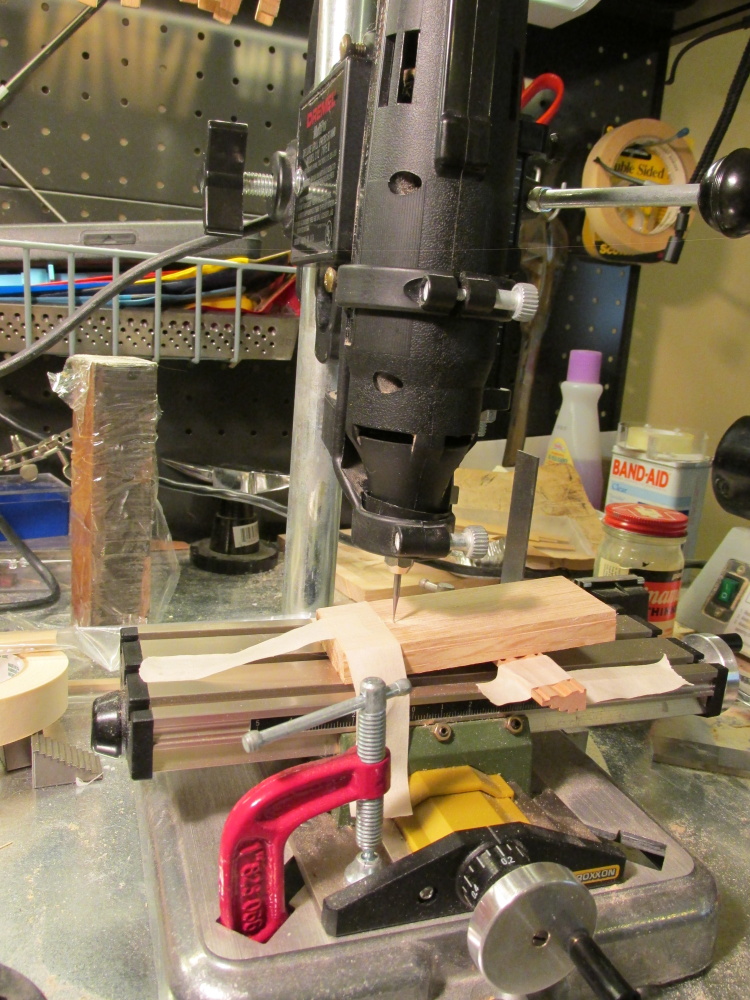
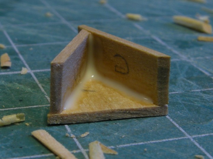
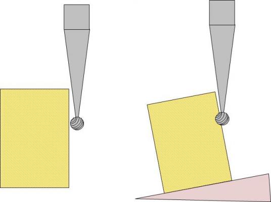
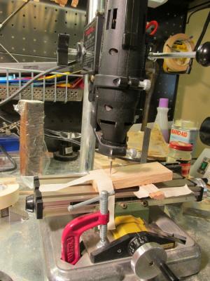
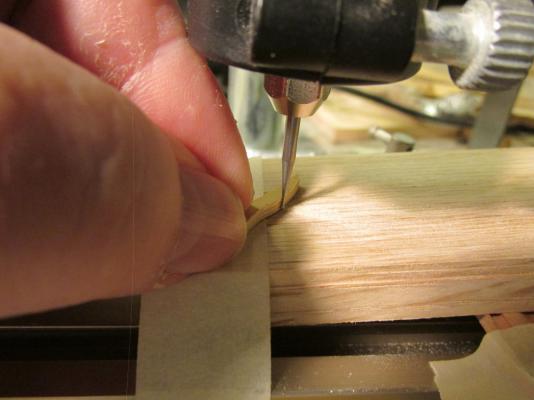
The idea was to make a router-like set-up without using a router bit. As shown in the diagrams below, if I set up the piece to be cut directly on the drill table, the bit doesn’t bite into the wood. The shaft blocks the bit from touching the wood. However, if the work surface is tilted then the bit can cut the wood. Additionally, by moving the work surface left or right using the x-y table, the bit can be adjusted up and down relative to the work surface due to the wedge. The wood is then ”routed” by hand. With a little experimenting and practice it seemed to work. NOTE: I have a new pocket camera (Cannon SX160 IS) with a terrific built-in macro capability. Now I can show you my screw ups in excruciating detail!

- 974 replies
-
- 4
-
-
- rattlesnake
- mamoli
- (and 1 more)
-
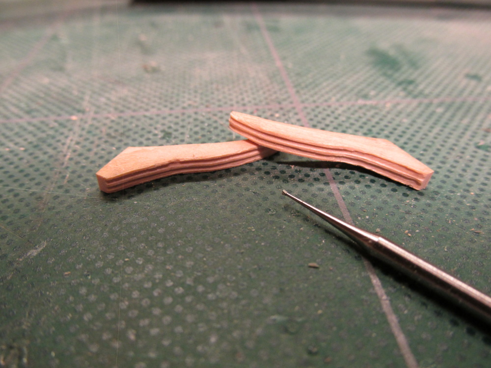
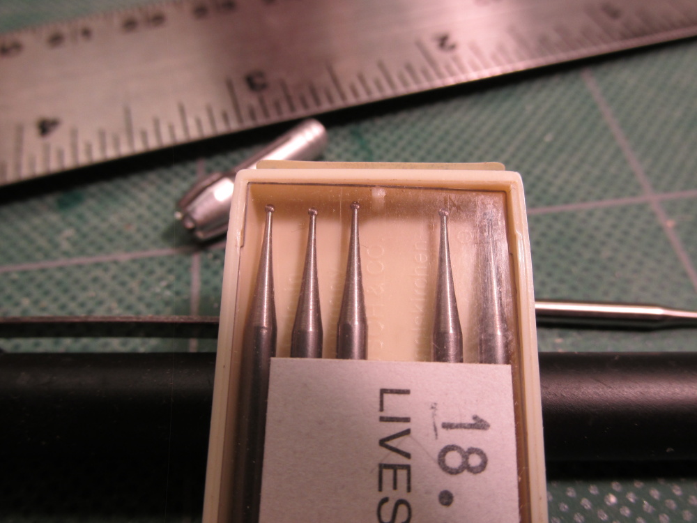
I made a new rig to create the moldings. Using one of my globe “dental drill bits” that I bought from Livesay’s when I was carving the transom ornaments a while back, in my rotary tool, the tool was inserted it into the rotary tool “drill press.“

-
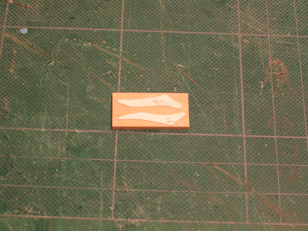
New week. - The upper wale cheeks were first made out of card stock then transferred to the 3/32” x ¼” boxwood.
-
Thanks for the carving tip. I'm going to attempt another technique I made up first and will let you know its results. Glad I could provide those photos of Pasi's build. I have all of them that he posted should you need them. As a side note, I bought a new computer Saturday because of the problems I reported earlier. I didn't want to sink money into an older computer. But as it turned out on Sunday, I finally got the computer working properly and returned the new one Monday. As much as I would have like to have a new computer, that's $1,000 I didn't have to spend. Maybe next year.
-
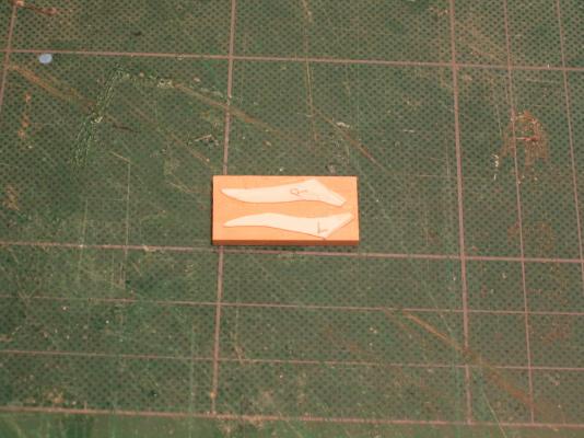
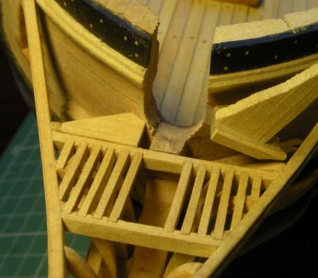
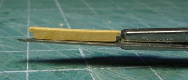
Head Rails According to the Practicum, I've come to “one of the most difficult areas of the ship model.” Don’t you just love that kind of encouragement? The first things to make are the cheek rails, a set of upper and lower rails starting from the wale area and working their way onto the stem. They are made in two parts: the wale component and the stem component. The first template was made for the top wale components from the Hahn plans, rubber cemented to 3/32” x ¼” boxwood, and cut out with the scroll saw. These pieces have a molding on their edge. Mr. Hunt stated that he used a #10 Exacto blade to form them. I don’t know how he did carve them that way. I used the razor blade method as I did on the other moldings. Let me tell you, cutting the razor blade was easy; cutting the razor blade with precision was not. I used an X-Y table on my Dremel “drill press” with the cutting discs attached to the Dremel held horizontal and the razor blade mounted vertical. I then could move the razor blade precisely. My first molding attempt worked but I was not satisfied. I made three grooves in the wood instead of two as shown and felt they didn't stand out very well. My second attempt was a disaster. Because the wale cheek has a wavy surface, drawing it across the razor blade was difficult especially because the piece was so small. Normally when making a molding, you work with a long straight strip and you a pulling with the grain of the wood. With the cheeks the pieces are very short and the grain changes due to the curvy shape of the wood. The stem component was supposed to be made from 1/8” x ½” boxwood but since the wood package did not come with this size, Mr. Hunt stated in the Practicum to glue two piece of 1/8” x ¼” to make it. I found this to be unsatisfactory. The stem cheek rails are slender and they will have to be carved not only with a molding but a design as well. I was afraid that in the process of hand carving the pieces, I could break the fragile glue joints. Therefore I ordered a 1/8” x ½” boxwood package from HobbyMill which consisted of two 24” pieces. I should have plenty of wood in about a week’s time should I screw up. Basically I accomplished nothing this week. To make matters worse I wanted to try using cutter bits (like what the dentist uses) but I've misplaced mine and wasted a bunch of time looking for them. No luck so far. Then the video card on my computer died. I was able to cannibalize an old card from a dead computer but now the image stretches to fill the 9x16 aspect ratio screen. Sometimes it just doesn't pay to get out of bed.
-
Found a few more. Sorry there not in order. I hope these help. And thank you Pasi Ahopelto

- 974 replies
-
- 1
-
-
- rattlesnake
- mamoli
- (and 1 more)
-
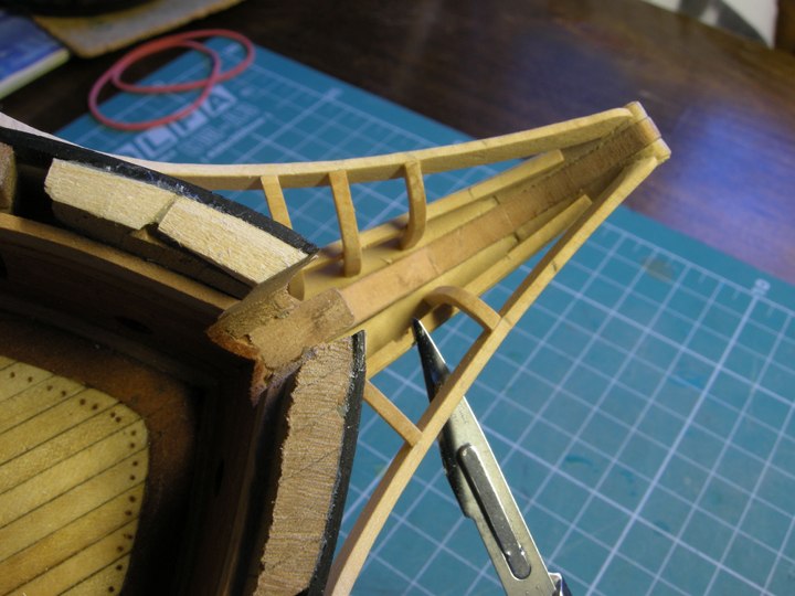
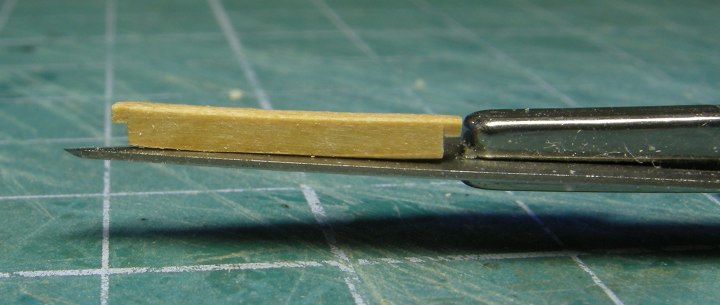
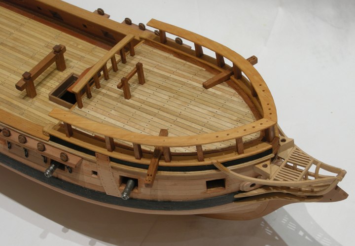
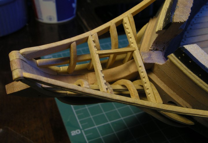
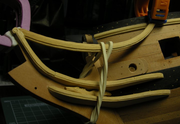
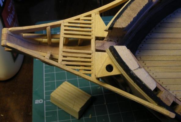
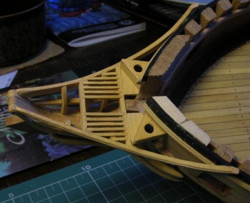
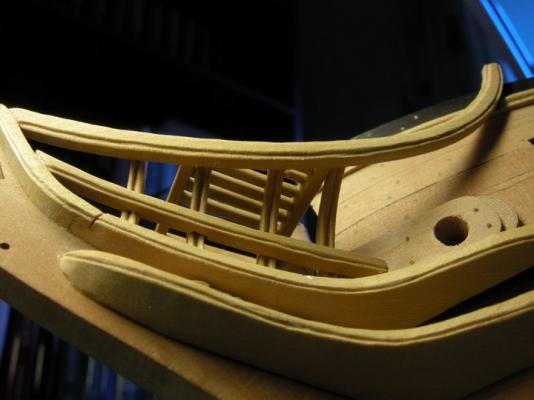
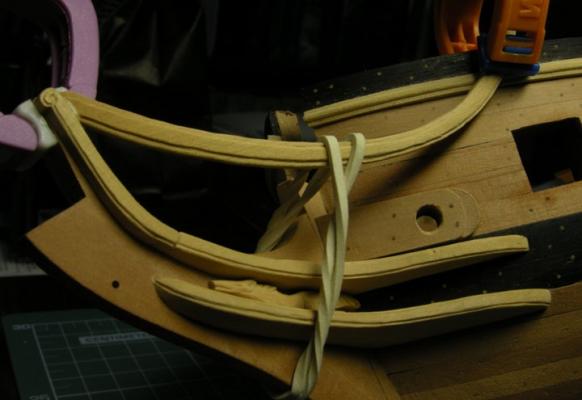
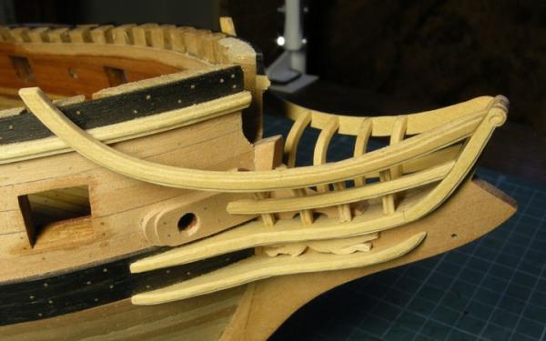
A few more images

-
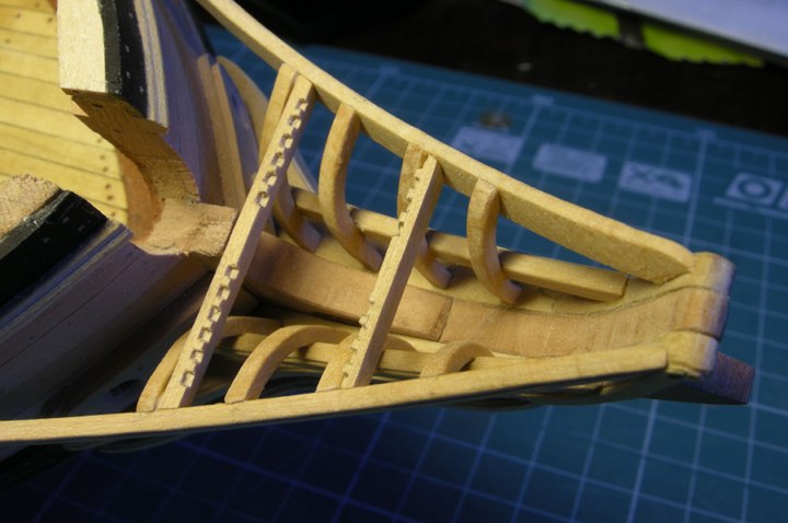
Thanks for the, ahem, encouragement. I have some images from Model Ship World 1.0 when Pasi Ahopelto had a running build log. He was following the Hahn's plans directly so his model was 1/4" = 1'. It was a wonderful log and a beautiful build but unfortunately when MSW 1.0 died, so did his build log. I however, in my infinite wisdom, had copied all of his images before this happened. Here for your use are his images on how he built the head rails.


-
How "neat a solution" it was will depend how long those lids will remain attached before I, like you, knock them off. They were a minor pain to attach. I am starting the head boards and that will require a lot of manipulation of the model as I manufacture, fit and install all of those little parts. Wish me luck!
-
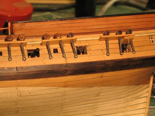
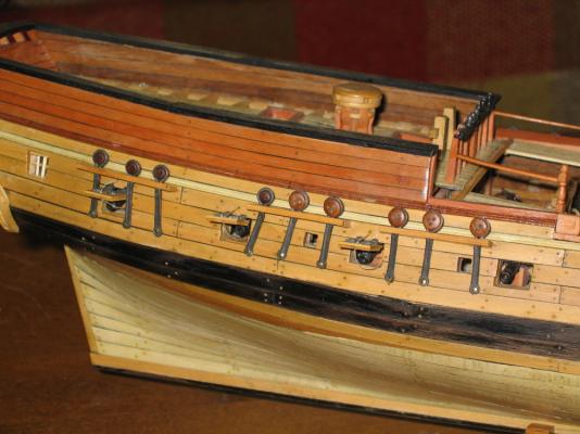
Then there is the matter of gun port lid tackle used to open and close the lid. The Practicum and Hahn’s drawings are silent in this regard. The Mamoli plan’s show a continuous rope from the inner hull through a hole just above the gunport and below the channels through a hole low in the lid which then hangs down inside the hull. I must assume there were knots or some other method by which the rope was secured to the lid on the actual ship. These would be too small to see at this scale. The Model Shipway plans (which I just got my hands on) show a ring on the outside of the gunport lid from which the rope is attached and then goes over the channels into the hull. Going over the channel doesn’t make sense as the rope would then be passing through the hull and appearing on the deck above. Nothing is shown as to how the lid was closed. Any ring that I could buy or fabricate would appear to my eyes too large for the scale of the model. Based on the above, I have elected to follow the Mamoli plans. The method of securing the rope to the lid is moot as far as I am concerned due to the scale. In actuality, beige thread was glued to a hole on the outside hull above the gunport and below the channel, passed through a hole in the lid at the lower end and glued to the inside hull as if it were secured by a cleat which the observer can’t see. To accomplish this, the thread was first glued to the outside hull above the gunport. Once set, it was threaded through the hole in the lid. The model was laid on its side and the lid was CA glued in place so it stood vertical. It was almost like balancing a pencil on its end. It was left this way for at least 30 minutes. I was taking no chances. This was done nine more times. This took a lot longer than I had expected. The result is shown below.


- 974 replies
-
- 2
-
-
- rattlesnake
- mamoli
- (and 1 more)
-
The practicum only stated that the lids were attached in an open position with no detail. It appears from the pictures provided that Mr. Hunt simply cut off the tongue from the bracket and just glued the lid edge directly to the hull. If one wants the look of hinges, then the use of the tongues is a must. The tongues on the brackets are rectangular in shape and cross section. Because the pseudo hinge had to appear at the gun port opening edge, a simple drilled hole would not work. The drill would not stay in place; grooves would have to be formed for the bracket tongues. I used a variable speed cordless rotary tool with a cone cutting bit. The picture below shows the three stage: Before, drilled holes, completed installation. The center gunport shows the grooves in the top of opening that is for the bracket tongues.