


JSGerson
-
Posts
2,650 -
Joined
-
Last visited
Reputation Activity
-

 JSGerson got a reaction from Unegawahya in USS Constitution by JSGerson - Model Shipways Kit No. MS2040
Peter, The US Navy plans I have. The 3-D printer I don't have, nor do I know of anyone who does have one. Cutting the brass 1/16" stock or the styrene 0.060" stock into cubes wasn't a real problem if you have a small miter box and a fine tooth saw. Cutting the brass rod and tubes also not a big deal. I used a fine tooth saw because if I used a cutting disk on a Dremel tool, the tiny piece pieces would fly off into Never-Never Land. I bought the brass balls. The hard part (for me at least), was trying to drill holes into the brass as I have documented.
Take it one step at a time, and it will come together. Albeit, there are a lot of steps. As for going to a larger scale, the 1:76 scale of the MS kit creates a four foot model. That in turn requires an even larger display box, which requires a display table large enough to properly show off the display box. Now increase the scale of the model and everything gets bigger. Oh, one other thing, usually a larger scale almost demands more detail. Be careful what you wish for.🤥
If you enjoy it, it not work
Jon
-

 JSGerson got a reaction from Der Alte Rentner in USS Constitution by Der Alte Rentner - Model Shipways - 1/76
I would never pass judgment on the model builder's choices, so much is involved. In this case, there is no correct selection for the carronades. Either you match what is on the the ship today and have the incorrect style armament or install the correct 1812 style guns and not be true to what the ship has on board. It's the builder's decision.
Jon
-
 JSGerson got a reaction from Geoff Matson in USS Constitution by JSGerson - Model Shipways Kit No. MS2040
I had to work out the sequence of CA gluing a block to a rail and sliding the block and rail component down the stanchion to the bottom position and have the rail slip into the block on the other stanchion with precision. Then do it again for the top rail. Those rails lengths had to be precise which meant nipping the ends of the rail and filing to shorten the brass rod within thousands of an inch by trial and error. Then gluing the rail into the block so it didn’t protrude into the stanchion’s vertical hole, about 1/64”. Invariably, I broke glue joints, crushed blocks, lost the tiny pieces if I dropped them, and had to refabricate numerous parts
Now I must bring 7 arched 1/32” brass rods together into a styrene ring that is to hold them together at the center of the stairwell and add a yet to be fabricated ornament it its center. So, this is as far as I got in all this time.
-
JSGerson got a reaction from Geoff Matson in USS Constitution by JSGerson - Model Shipways Kit No. MS2040
I thought assembling the pieces was going to straight forward, so I painted the blocks with brass color paint which as it turned out, was a bit more copper in color than the actual brass parts. Attaching a block to the stanchions was basic, however attaching the horizontal rails was not.
-
JSGerson got a reaction from Geoff Matson in USS Constitution by JSGerson - Model Shipways Kit No. MS2040
Now the fun began. Making the connector blocks for the canopy stanchions was very delicate and tedious. My original plan required two to three drill press setups per block depending on whether it was for a corner, an open end or inner stanchion. Changing the setup was required because of the two different sized brass rod/tubes that needed to fit into the blocks. After a few haphazard starts, I realized that all that was necessary was to drill a 1/32” passthrough hole with the drill press for the 3/32” brass tube which will be the vertical stanchion. This hole left an opening with only a 1/64” wall outside of the hole. Precision was required. The other holes for the 0.020” rod (horizonal rails), were a little more forgiving and was done with a hand drill fairly quickly. Cutting the 1/16” cube from the 1/16” square styrene rod was done with my mini miter block with a properly set stop and a razor saw. However, a 1/16” cube of styrene with holes drilled through it almost to its edges created a very fragile component with very little surface area remaining for gluing. I slipped on the unpainted styrene blocks again for fit.
-
JSGerson got a reaction from Geoff Matson in USS Constitution by JSGerson - Model Shipways Kit No. MS2040
It has been over a month since my last posting of the progress of my model. I have not been idle but working on it at my usual pace…slowly. I made very little progress considering the time I spent.
For the first railing and canopy structure I chose the companionway and skylight frame because it was large and looked like it was the easiest. I drilled seven 1/16” holes for the 1/16” base sleeves which were cut from a 1/16” brass tube. The stanchions were cut from 3/32” brass tube and inserted into the sleeves for fit.
-
 JSGerson got a reaction from KARAVOKIRIS in USS Constitution by JSGerson - Model Shipways Kit No. MS2040
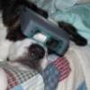
I am taking my canopy frame fabrication cues from several builders but am using 1/32” brass tube instead of 1/32” brass rod as many other builders have used for the vertical components. This allows me to use a continuous vertical component, passing through the junction blocks and decorative balls to just beyond the top railing. Then the overhead canopy support made of 0.02” brass rod can be inserted into the 1/32” tube creating a strong mechanical connection. The 0.06” blocks will only support the horizontal rails with no stress. The brass balls are strictly ornamental and provide no support. The tricky part is where the canopy arches all meet at the top. A hub piece will be used to connect all the arches plus the finial. The finial is to be comprised of a rod and tube configuration (TBD), and filed into its final shape and inserted into the hub. The vertical framework base will be inserted into rings made from 1/16” tubes, embedded into the grating wood frames. Here is a summary of the materials:
Base of vertical component: 1/16” brass tube – K&S Engineering No. 5125 Vertical component: 1/32” brass tube– K&S Engineering No. 815035 Horizontal component: 1/32” brass rod - K&S Engineering No. Junction blocks: 0.06” Styrene square rod – Evergreen No. 223 Ornament: 1/32” brass balls – Tribal Desert from Etsy Junction hub: 3/32” styrene tube – Evergreen No. 153 So here is my plan based on the US Navy plans and the trial prototypes of the vertical components and the canopy hub element to see if this would work. The prototype is purely concept, so it is not adjusted for proper dimensions or glued and yet it stands on its own. The final image shows the styrene painted brass. It appears it just might work.
-
 JSGerson got a reaction from kmart in USS Constitution by JSGerson - Model Shipways Kit No. MS2040
I had to work out the sequence of CA gluing a block to a rail and sliding the block and rail component down the stanchion to the bottom position and have the rail slip into the block on the other stanchion with precision. Then do it again for the top rail. Those rails lengths had to be precise which meant nipping the ends of the rail and filing to shorten the brass rod within thousands of an inch by trial and error. Then gluing the rail into the block so it didn’t protrude into the stanchion’s vertical hole, about 1/64”. Invariably, I broke glue joints, crushed blocks, lost the tiny pieces if I dropped them, and had to refabricate numerous parts
Now I must bring 7 arched 1/32” brass rods together into a styrene ring that is to hold them together at the center of the stairwell and add a yet to be fabricated ornament it its center. So, this is as far as I got in all this time.
-
 JSGerson got a reaction from PaddyO in USS Constitution by JSGerson - Model Shipways Kit No. MS2040
I thought assembling the pieces was going to straight forward, so I painted the blocks with brass color paint which as it turned out, was a bit more copper in color than the actual brass parts. Attaching a block to the stanchions was basic, however attaching the horizontal rails was not.
-
JSGerson got a reaction from PaddyO in USS Constitution by JSGerson - Model Shipways Kit No. MS2040
Now the fun began. Making the connector blocks for the canopy stanchions was very delicate and tedious. My original plan required two to three drill press setups per block depending on whether it was for a corner, an open end or inner stanchion. Changing the setup was required because of the two different sized brass rod/tubes that needed to fit into the blocks. After a few haphazard starts, I realized that all that was necessary was to drill a 1/32” passthrough hole with the drill press for the 3/32” brass tube which will be the vertical stanchion. This hole left an opening with only a 1/64” wall outside of the hole. Precision was required. The other holes for the 0.020” rod (horizonal rails), were a little more forgiving and was done with a hand drill fairly quickly. Cutting the 1/16” cube from the 1/16” square styrene rod was done with my mini miter block with a properly set stop and a razor saw. However, a 1/16” cube of styrene with holes drilled through it almost to its edges created a very fragile component with very little surface area remaining for gluing. I slipped on the unpainted styrene blocks again for fit.
-
JSGerson got a reaction from PaddyO in USS Constitution by JSGerson - Model Shipways Kit No. MS2040
It has been over a month since my last posting of the progress of my model. I have not been idle but working on it at my usual pace…slowly. I made very little progress considering the time I spent.
For the first railing and canopy structure I chose the companionway and skylight frame because it was large and looked like it was the easiest. I drilled seven 1/16” holes for the 1/16” base sleeves which were cut from a 1/16” brass tube. The stanchions were cut from 3/32” brass tube and inserted into the sleeves for fit.
-
JSGerson got a reaction from PaddyO in USS Constitution by JSGerson - Model Shipways Kit No. MS2040
I had to work out the sequence of CA gluing a block to a rail and sliding the block and rail component down the stanchion to the bottom position and have the rail slip into the block on the other stanchion with precision. Then do it again for the top rail. Those rails lengths had to be precise which meant nipping the ends of the rail and filing to shorten the brass rod within thousands of an inch by trial and error. Then gluing the rail into the block so it didn’t protrude into the stanchion’s vertical hole, about 1/64”. Invariably, I broke glue joints, crushed blocks, lost the tiny pieces if I dropped them, and had to refabricate numerous parts
Now I must bring 7 arched 1/32” brass rods together into a styrene ring that is to hold them together at the center of the stairwell and add a yet to be fabricated ornament it its center. So, this is as far as I got in all this time.
-
JSGerson got a reaction from Unegawahya in USS Constitution by JSGerson - Model Shipways Kit No. MS2040
I had to work out the sequence of CA gluing a block to a rail and sliding the block and rail component down the stanchion to the bottom position and have the rail slip into the block on the other stanchion with precision. Then do it again for the top rail. Those rails lengths had to be precise which meant nipping the ends of the rail and filing to shorten the brass rod within thousands of an inch by trial and error. Then gluing the rail into the block so it didn’t protrude into the stanchion’s vertical hole, about 1/64”. Invariably, I broke glue joints, crushed blocks, lost the tiny pieces if I dropped them, and had to refabricate numerous parts
Now I must bring 7 arched 1/32” brass rods together into a styrene ring that is to hold them together at the center of the stairwell and add a yet to be fabricated ornament it its center. So, this is as far as I got in all this time.
-
JSGerson got a reaction from KARAVOKIRIS in USS Constitution by JSGerson - Model Shipways Kit No. MS2040
I had to work out the sequence of CA gluing a block to a rail and sliding the block and rail component down the stanchion to the bottom position and have the rail slip into the block on the other stanchion with precision. Then do it again for the top rail. Those rails lengths had to be precise which meant nipping the ends of the rail and filing to shorten the brass rod within thousands of an inch by trial and error. Then gluing the rail into the block so it didn’t protrude into the stanchion’s vertical hole, about 1/64”. Invariably, I broke glue joints, crushed blocks, lost the tiny pieces if I dropped them, and had to refabricate numerous parts
Now I must bring 7 arched 1/32” brass rods together into a styrene ring that is to hold them together at the center of the stairwell and add a yet to be fabricated ornament it its center. So, this is as far as I got in all this time.
-
JSGerson got a reaction from Unegawahya in USS Constitution by JSGerson - Model Shipways Kit No. MS2040
I thought assembling the pieces was going to straight forward, so I painted the blocks with brass color paint which as it turned out, was a bit more copper in color than the actual brass parts. Attaching a block to the stanchions was basic, however attaching the horizontal rails was not.
-
JSGerson got a reaction from Unegawahya in USS Constitution by JSGerson - Model Shipways Kit No. MS2040
Now the fun began. Making the connector blocks for the canopy stanchions was very delicate and tedious. My original plan required two to three drill press setups per block depending on whether it was for a corner, an open end or inner stanchion. Changing the setup was required because of the two different sized brass rod/tubes that needed to fit into the blocks. After a few haphazard starts, I realized that all that was necessary was to drill a 1/32” passthrough hole with the drill press for the 3/32” brass tube which will be the vertical stanchion. This hole left an opening with only a 1/64” wall outside of the hole. Precision was required. The other holes for the 0.020” rod (horizonal rails), were a little more forgiving and was done with a hand drill fairly quickly. Cutting the 1/16” cube from the 1/16” square styrene rod was done with my mini miter block with a properly set stop and a razor saw. However, a 1/16” cube of styrene with holes drilled through it almost to its edges created a very fragile component with very little surface area remaining for gluing. I slipped on the unpainted styrene blocks again for fit.
-
JSGerson got a reaction from Unegawahya in USS Constitution by JSGerson - Model Shipways Kit No. MS2040
It has been over a month since my last posting of the progress of my model. I have not been idle but working on it at my usual pace…slowly. I made very little progress considering the time I spent.
For the first railing and canopy structure I chose the companionway and skylight frame because it was large and looked like it was the easiest. I drilled seven 1/16” holes for the 1/16” base sleeves which were cut from a 1/16” brass tube. The stanchions were cut from 3/32” brass tube and inserted into the sleeves for fit.
-
 JSGerson got a reaction from Stevenleehills in USS Constitution by JSGerson - Model Shipways Kit No. MS2040
I had to work out the sequence of CA gluing a block to a rail and sliding the block and rail component down the stanchion to the bottom position and have the rail slip into the block on the other stanchion with precision. Then do it again for the top rail. Those rails lengths had to be precise which meant nipping the ends of the rail and filing to shorten the brass rod within thousands of an inch by trial and error. Then gluing the rail into the block so it didn’t protrude into the stanchion’s vertical hole, about 1/64”. Invariably, I broke glue joints, crushed blocks, lost the tiny pieces if I dropped them, and had to refabricate numerous parts
Now I must bring 7 arched 1/32” brass rods together into a styrene ring that is to hold them together at the center of the stairwell and add a yet to be fabricated ornament it its center. So, this is as far as I got in all this time.
-
JSGerson got a reaction from KARAVOKIRIS in USS Constitution by JSGerson - Model Shipways Kit No. MS2040
I thought assembling the pieces was going to straight forward, so I painted the blocks with brass color paint which as it turned out, was a bit more copper in color than the actual brass parts. Attaching a block to the stanchions was basic, however attaching the horizontal rails was not.
-
JSGerson got a reaction from KARAVOKIRIS in USS Constitution by JSGerson - Model Shipways Kit No. MS2040
Now the fun began. Making the connector blocks for the canopy stanchions was very delicate and tedious. My original plan required two to three drill press setups per block depending on whether it was for a corner, an open end or inner stanchion. Changing the setup was required because of the two different sized brass rod/tubes that needed to fit into the blocks. After a few haphazard starts, I realized that all that was necessary was to drill a 1/32” passthrough hole with the drill press for the 3/32” brass tube which will be the vertical stanchion. This hole left an opening with only a 1/64” wall outside of the hole. Precision was required. The other holes for the 0.020” rod (horizonal rails), were a little more forgiving and was done with a hand drill fairly quickly. Cutting the 1/16” cube from the 1/16” square styrene rod was done with my mini miter block with a properly set stop and a razor saw. However, a 1/16” cube of styrene with holes drilled through it almost to its edges created a very fragile component with very little surface area remaining for gluing. I slipped on the unpainted styrene blocks again for fit.
-
JSGerson got a reaction from KARAVOKIRIS in USS Constitution by JSGerson - Model Shipways Kit No. MS2040
It has been over a month since my last posting of the progress of my model. I have not been idle but working on it at my usual pace…slowly. I made very little progress considering the time I spent.
For the first railing and canopy structure I chose the companionway and skylight frame because it was large and looked like it was the easiest. I drilled seven 1/16” holes for the 1/16” base sleeves which were cut from a 1/16” brass tube. The stanchions were cut from 3/32” brass tube and inserted into the sleeves for fit.
-
 JSGerson got a reaction from Coyote_6 in Rattlesnake by JSGerson - FINISHED - Mamoli - 1:64 - Using Robert Hunt’s practicum
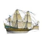
This is a big milestone: All of the rigging is installed. That being said, there still some work to be done:
· Belay all the remaining lines
· Repair:
o Rudder straps – some of the original paper ones came off
o Anchor tie down line – replace snapped line
o Gunport doors – glue back on
· Add the flags with their associated blocks and halyards
· Rework the model stand – the model wobbles too much
· Buy the cut Plexiglas for the case
· Stain and assemble the model case
· Obtain a table for the case to sit on
-

 JSGerson got a reaction from DARIVS ARCHITECTVS in Rattlesnake by JSGerson - FINISHED - Mamoli - 1:64 - Using Robert Hunt’s practicum
The last pictures will be posted when the case is finalized, the model cradle is tweaked, and the model is inside.
-
 JSGerson got a reaction from Auger in Rattlesnake by JSGerson - FINISHED - Mamoli - 1:64 - Using Robert Hunt’s practicum
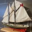
FINISHED
Well here they are, the last planned official images of my Rattlesnake, safe and snug in her case. For those who followed my loooonnnnnng and s l o w build over the past seven years, once again, thank you for being so patient and thank you for all the “likes.”
-
JSGerson got a reaction from Auger in Rattlesnake by JSGerson - FINISHED - Mamoli - 1:64 - Using Robert Hunt’s practicum
The last pictures will be posted when the case is finalized, the model cradle is tweaked, and the model is inside.