
HOLIDAY DONATION DRIVE - SUPPORT MSW - DO YOUR PART TO KEEP THIS GREAT FORUM GOING!
×


Force9
-
Posts
405 -
Joined
-
Last visited
Reputation Activity
-

 Force9 reacted to wglasford in USS Missouri by wglasford - Trumpeter - 1/200 - PLASTIC
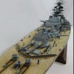
Back to working on this model. Took a break to complete all the other mostly completed models and even created a 3D printed model of The Big Carl crane. This is now the only model I have in-progress, a final push to get this one complete. Continuing to work my way up the superstructure, creating the smoke stacks and main stack. Things have gone from mostly plastic parts to mostly photo etch. And the parts are getting really small and fragile. These little hatches are 2x3mm in size. The ends of the tweezers are feeling really big.
Here are pictures of the forward tower/smoke stack and the aft smoke stack. They are not glued on yet because more parts need to go on and some of it still needs to be painted. I'm holding off on adding the more delicate parts.
-
Force9 reacted to MisterMeester in RMS Titanic by MisterMeester - Trumpeter - 1/200 - PLASTIC
Doubling plates (all 180 of them) attached. Used CA glue for these. Parts A - D now complete. I found Part CU-2 backplate to be the most difficult. Particularly on the Stbd side (circled in red). It popped off under stress from handling. Re-attached with epoxy. Unfortunately I re-attached it without paying attention to alignment. Thus, it is slightly off by about 1-2mm longitudinally. Shouldn't be a big deal and hardly noticeable.
Up next, as per instructions, with this PE kit is to prepare the hull. However, before engaging in that surgery, I want to do somewhat of a dry fit first. As well, there are other hull features still to be attached. For attaching the bilge keels and propeller/shaft wings I expect I'm going to want to flip the hull upside down. I'm quite certain that would not be a good idea with this PE in place.
Further, kit parts N1 & N2 and P1 & P2 (for A, B, and C decks) come into play with this PE. Having said that, it's time to install the internal frame aftermarket kit. Original plan was to install the frame kit after painting the hull, as it would be much easier to install the porthole "glass" without the frames in place. But that plan was before I decided on this PE kit, and plans change.
Glueing one frame at a time. I did not have a bar clamp large enough for this, so went out and bought one. At $18.99 CDN each (on sale, down from $29.99) it made more sense to get just one, instead of four.
In the meantime, prior to starting on the internal framing, I was pondering the lowest row of molded indentations on the hull, which represent through hull fittings. Common advice regarding these is to DON'T DRILL THESE OUT(!). But wait.....I'm not lighting my model, and therefore, there would be no light leakage through these if they were drilled. I decided the overall look will be better with them drilled. Left undrilled, some of them will end up painted over with antifouling red. Done.
Second frame glued in this morning. Two more to go. Should have that completed within a couple of days. After that will be the bilge keels and propeller/shaft wings.
Thanks for looking.
Cheers,
Mark
-
 Force9 got a reaction from GrandpaPhil in TITANIC by Force9 – Trumpeter - 1/200 - PLASTIC - White Star Liner
Installing the starboard Bilge Keel
Sorry for the extra-long delay on updates… Lots of travel and a minor health adventure. The garage has cooled down after a very warm summer and I’m back at the workbench.
I thought installing the starboard bilge keel would be an easy exercise to get back into the build.
Of course, I made it harder than I thought it would be…
I didn’t love the lower hull butt straps that I had placed earlier. It gnawed at me that they could not align to a single strake that spanned the length of the hull just above the bilge keel.
Trumpeter’s versions of the strakes in this area are all over the place. The edges of the strakes on the model change as you move fore to aft without a consistent edge to align against the tops of the straps.
This becomes especially problematic once the keel is installed since the top halves of some butt straps need to be added along the upper edge of the bilge keel. They will look odd if they don’t align to the edge of a single contiguous strake.
Argh.
I decided to scrape off the previous effort and begin anew.
This time I added a new strake running above the length of the bilge keel using very thin .005 strips that I fashioned using my Fiskar paper cutter:
I then filled in the in/out strakes in this area using .010 strips (and liberal globs of Tamiya putty).
I also added a new strake below the keel to help align the bottom edges of the butt straps.
Everything was sanded smooth in preparation for adding the bilge keel and the new butt straps.
Using the keel outline on the model, I cemented the new bilge keel in place – but left a few inches on either end free to move:
I’ll try to spoof the eye of the viewer into thinking the Trumpeter hull has more curve than it does.
I slightly bent the ends upward – very subtle – and cemented them down to give the keel a bit of a smile. The real ship would have a rounded shape in this area of the hull that would allow the bilge keels to curve upward. You can see that in any profile drawings available in books or online.
Aft end keel bilge view:
Now to add the new butt straps.
Using Bob Read’s starboard profile as a reference, I determined the number of Butt Straps needed along the length of the keel (eleven) and created a spacer from scrap styrene to mark the equally spaced locations:
I again used the paper cutter and some thin .005 sheet to create the straps. I don’t want them to stand too proud from the hull.
They were all trimmed and cemented with their top edges against the newly created upper strake, with the bottom edges against the new lower strake.
Along the length of the bilge keel, I custom trimmed the top half of each strap to fit between the bottom edge of the new strake above and the top edge of the keel and cemented them in place based on the pre-marked locations.
The bottom half of the straps were similarly trimmed and cemented into place between the bottom edge of the keel and the new strake below.
A wide view to see the effect:
This representation is closer to reality.
I think I’m satisfied. Hopefully I won’t need to revisit these again!
Next up – The starboard B and C deck profile/sides:
Cheers,
Evan
-
Force9 got a reaction from GrandpaPhil in TITANIC by Force9 – Trumpeter - 1/200 - PLASTIC - White Star Liner
The after Well Deck (Starboard)
I moved aft and continued the thinning of the Well Deck bulwarks.
The drill was again put to work… I removed a section starting an inch or so behind the aft end of the break (where the kit molding changes thickness) and extending a bit forward of where the break ends (to give a bit of wiggle room to for a future modification).
A quick pass with the hand saw will finish the job.
I use a sturdy file to clean the jagged edge:
Finally, I’ll need to use a medium and fine file to get a clean opening:
Now to add the bulwark.
This was similarly outlined on a small sheet of .020” styrene as we saw on the forward well deck.
I created a mockup to make sure everything fit in the opening. I used the KA brass bulwark as a template to determine the gangway door locations. I moved the wash port openings a bit higher to allow for the additional interior bulwark details to clear the Trumpeter decking with the added thickness of the wood deck veneer on top. Details were added using thin .010” strip.
I installed the new bulwark and then etched the outlines of the gangway doors on the exterior.
It all looked good – until it didn’t. Something was amiss…
Have a look at the aft Well Deck exterior detail extracted from Robert Read’s profile:
I really need to account for all the areas highlighted… The doubling strakes need to be added along with the strake below to give the correct dimension to the side.
Additionally, I need to reconsider the wash ports. Many modelers complain that @#$@ Trumpeter did not completely open the aft well deck wash ports and they must put in the extra effort to open them up.
The kit has an indentation to show their location, but they are molded with a solid interior.
Ugh.
or… maybe…they got that almost right…?
It seems to me that all the photos/representations showing these wash ports on the Titanic always have them with their covers closed over the openings. I can’t find an exception. I suspect that Trumpeter was trying to compromise – show the wash ports, but represent a cover on the interior.
I ripped out the newly installed bulwark and started over.
I cut another bulwark using the template I had already made for the first pass. This time I used .015” styrene for the main bulwark piece.
I then added a strip of .005” styrene that I cut using my new (and very masculine) Fiskar paper cutter. I purchased this at a steep discount during an online sale a few months ago.
This is very useful for cutting strips of .005” up to .020” styrene sheet.
I shaped the gangway doors using .005” styrene and added them to the exterior. Then I inserted filler strips shaped to match the curve of the doors (Circled below) and extended the strake across the bulwark piece - protruding a bit on each end. This’ll help merge everything into the kit and keep it flush to the sides.
I drilled the mooring openings and added thin .005” styrene to represent the closed wash port covers.
The result is ready to install.
The seams were filled with Tamiya putty diluted with Lacquer thinner and sanded smooth.
The doubling strake can now be added using more of the .005” styrene strips made using the Fiskar cutter.
More .005” strip was added to the lower strake to give additional dimension. The ports were re-drilled from the inside.
New doubling straps were strategically placed to hide the ends of the new pieces. These were fashioned from .005” strip with rivets added using another fun new tool:
This is a “corner” rivet tool that allows for accurate embossing of the parallel rivet pattern on small styrene strip:
Apply even pressure to get the indentations, then flip over and cement in place.
Finally, I did some careful filing to smooth the top edge.
I think this’ll work.
I’ll add the interior detail on the next post.
Cheers,
Evan
-
Force9 got a reaction from GrandpaPhil in TITANIC by Force9 – Trumpeter - 1/200 - PLASTIC - White Star Liner
The Bilge Keel
The kit provided bilge keels are – no surprise – subpar. No hate on Trumpeter here… It’s nearly impossible to create an accurate keel using injection molding. It’d be too thin and would likely warp as it cooled on the sprue.
So, the kit version is very thick/heavy and lacks any of the detail that the actual keel would show.
Here is what TITANIC – TSM shows for these keels:
You can see that we need thinner representations with doubling strips top and bottom along with a narrow cope along the outer edge of the underside.
I think there have been 3D print versions for these, but that seems like overkill. These are very easy to scratch build at minimal cost. Any modeler can (and should) make these.
I purchased some Styrene T pieces from PLASTRUCT:
These are long – 24” – so that I don’t need to combine smaller lengths. Just trim the piece to fit the outline on the model. I found these at the nearby Model Railroad store. Those guys build model bridges with this stuff.
First, I shaped the curvature on both ends using my hobby knife and a quick pass with a medium metal file.
Next, I dipped into my stash for various strips to add the cope and doubling/reinforcement:
I’ll use the wider .080” strip for the top surface and the slightly smaller .060” on the underside. That’ll generally align to what the TSM diagram shows.
A quick test fit to confirm that the basic dimensions align to what is needed for the scale:
Couldn’t be easier to lay down the topside .080“ styrene strip… Just rest it in position against the inner corner of the T, apply some thin cement, and let the capillary action fill in underneath. It takes two pieces to cover the distance. I just matched the factory ends together for a tight fit. The seam is basically invisible. Let the smaller length extend a bit beyond the end of the T piece and trim to fit after it sets.
Flip it over and do the same on the underside using the .060” strip.
Finally add the .010” x .020” cope to the underside edge. I used a small metal ruler to help align to the edge as I applied cement:
The underside completed:
A meaningful improvement over the kit version, I think.
It just takes a few minutes to whip these together. Fun to build for anyone wanting to try a little scratch building on their Titanic.
I’ve decided to hold off a bit longer on installation… These would be vulnerable as I continue to flip the hull around on various other add-ons.
The starboard after well deck bulwark is up next.
Cheers,
Evan
-
Force9 got a reaction from GrandpaPhil in TITANIC by Force9 – Trumpeter - 1/200 - PLASTIC - White Star Liner
The Gangway doors
A quick thought exercise…
The future positioning of the open Gangway door on my model is a bit of a puzzle.
My initial understanding was that these gangway doors were REMOVABLE… slide out the upper bolts, loosen the detachable iron stays, lift the gangway door away and stack it off to the side while loading cargo.
I see these referenced as removable doors in many Titanic forums. This is supported by a caption on a photo in TITANIC THE SHIP MAGNIFICENT book:
But alas… This is contradicted by the diagram on the opposite page where these are described by the author as FOLDING gangway doors:
Hmm…
If these are indeed folding doors, then how do they work?
It might make sense that these gangway doors hinge 180 degrees outboard and lie flat against the hull during cargo transfers. That would keep the doors out of the way and the deck clear. But these are heavy and could be problematic to pull back up into position. They could also damage the sides and paint if they swing all the way down.
Alternatively, there seem to be photos/video from the wreck showing these gangways swung 90 degrees outboard and resting on their hinges. Presumably the sliding bolts melted away and the detachable iron stays rusted thru leaving these doors hanging precariously outboard.
But that can’t be the correct position while loading cargo. They’d be in the way and subject to damage as loads were swung up and inboard by the cranes.
Hmm…
I think Robert Read provides the answer. His excellent overview of the Titanic Hatch Coamings (“Titanic-Hatch-Coamings-Color” that can be found in his Titanic CAD collection) includes a grainy historic photo showing the handling of cargo on the forward well deck:
Have a look at the circled portion of the photo… Aha. We see the gangway door folded inboard and lying flat on the deck with the detachable iron stays protruding out from underneath. Note the white coaming strip and the yellow sheer stripe painted on the outer surface of the gangway door.
This seems to undermine the idea that these doors were removable. Instead, it looks like these are folding doors that stay attached to the bulwarks and hinge inward to provide the pass-thru for cargo being swung on board.
I’ll replicate this when I eventually reach this stage.
Next up – The Bilge Keel:
Cheers,
Evan
-
Force9 got a reaction from GrandpaPhil in TITANIC by Force9 – Trumpeter - 1/200 - PLASTIC - White Star Liner
@Jeff59 - The hull modifications have not YET pushed me over the edge... Stay tuned. Speaking of temporary insanity - Great to see your progress on the Bismarck.
@md1400cs Thanks for keeping up with my build. I appreciate the encouragement.
More Starboard Well Deck Bulwark Detail
I’ve made progress on the Well Deck.
Details have been added to the interior of the bulwark:
Sliding bolts, bulwark stay rods, etc. will be added at a later stage. I’ll likely utilize the KA PE versions of the rigging pad eyes.
The exterior has also been refined a bit.
You can see the doubling strake is in place as well as doubling plates. These plates are only the underlying beds at this point… I will come back and add a top layer to these using the thinnest styrene sheet that will include the rivet pattern.
Additionally, the coping strip has now been extended across the new piece using .10” x .20” Styrene strip. This is also added along the top edge of the Fo’c’sle wash plate that was recently added.
A bit tricky to keep it straight along the edge – a small metal ruler was a useful guide while gluing.
More fun to come.
Cheers,
Evan
-
Force9 got a reaction from GrandpaPhil in TITANIC by Force9 – Trumpeter - 1/200 - PLASTIC - White Star Liner
The Forward Well Deck Bulwark (Starboard)
Time now to install the starboard bulwark replacement… Let’s see how it fits.
I made the section a bit longer on the aft end so that I could carefully file the end a bit at a time to get a perfect fit.
Once satisfied, I first cemented down the forward upright side – paying particular attention to aligning the facing of the new section with the outboard hull edge.
Next, I cemented down three strips along the base and lined up the new piece with the hull across the bottom – again paying particular attention to exact alignment to the outer hull surface. Since there is a slight curve to the hull along this edge, I divided the strip into three sections so that there wouldn’t be any tension pushing outward along the length of the new bulwark.
Lastly, I cemented the aft edge to align with the edge of the hull – paying particular attention… blah, blah.
The small gaps are fine… easily filled in and smoothed over at a later step.
You can see the significant improvement in the scale width of the bulwark. Not to say it is exact to what the true scale would need to be – but close enough for me. Using the .020” sheet gives enough stiffness to work without the risk of warping when the inner details are applied.
I did not add the inner stiffeners and other details “off the model” ahead of installation. That would be wasted effort if for some reason I messed up the fit and alignment of the new section and had to start over. (ask me how I know) Instead, I’ll add those details in situ after I’m satisfied with the fit.
The gap that is created with the thinner bulwark will be handled with filler pieces. Once the Scaledecks piece is in place, the space will get filled with the “Limber Board” that overlays on top of the deck along the inboard edge of the bulwark.
I’ll follow up to show some of the detail in place, then move on to the aft well deck starboard bulwark.
Cheers,
Evan
-
 Force9 got a reaction from madtatt in TITANIC by Force9 – Trumpeter - 1/200 - PLASTIC - White Star Liner
Installing the starboard Bilge Keel
Sorry for the extra-long delay on updates… Lots of travel and a minor health adventure. The garage has cooled down after a very warm summer and I’m back at the workbench.
I thought installing the starboard bilge keel would be an easy exercise to get back into the build.
Of course, I made it harder than I thought it would be…
I didn’t love the lower hull butt straps that I had placed earlier. It gnawed at me that they could not align to a single strake that spanned the length of the hull just above the bilge keel.
Trumpeter’s versions of the strakes in this area are all over the place. The edges of the strakes on the model change as you move fore to aft without a consistent edge to align against the tops of the straps.
This becomes especially problematic once the keel is installed since the top halves of some butt straps need to be added along the upper edge of the bilge keel. They will look odd if they don’t align to the edge of a single contiguous strake.
Argh.
I decided to scrape off the previous effort and begin anew.
This time I added a new strake running above the length of the bilge keel using very thin .005 strips that I fashioned using my Fiskar paper cutter:
I then filled in the in/out strakes in this area using .010 strips (and liberal globs of Tamiya putty).
I also added a new strake below the keel to help align the bottom edges of the butt straps.
Everything was sanded smooth in preparation for adding the bilge keel and the new butt straps.
Using the keel outline on the model, I cemented the new bilge keel in place – but left a few inches on either end free to move:
I’ll try to spoof the eye of the viewer into thinking the Trumpeter hull has more curve than it does.
I slightly bent the ends upward – very subtle – and cemented them down to give the keel a bit of a smile. The real ship would have a rounded shape in this area of the hull that would allow the bilge keels to curve upward. You can see that in any profile drawings available in books or online.
Aft end keel bilge view:
Now to add the new butt straps.
Using Bob Read’s starboard profile as a reference, I determined the number of Butt Straps needed along the length of the keel (eleven) and created a spacer from scrap styrene to mark the equally spaced locations:
I again used the paper cutter and some thin .005 sheet to create the straps. I don’t want them to stand too proud from the hull.
They were all trimmed and cemented with their top edges against the newly created upper strake, with the bottom edges against the new lower strake.
Along the length of the bilge keel, I custom trimmed the top half of each strap to fit between the bottom edge of the new strake above and the top edge of the keel and cemented them in place based on the pre-marked locations.
The bottom half of the straps were similarly trimmed and cemented into place between the bottom edge of the keel and the new strake below.
A wide view to see the effect:
This representation is closer to reality.
I think I’m satisfied. Hopefully I won’t need to revisit these again!
Next up – The starboard B and C deck profile/sides:
Cheers,
Evan
-
 Force9 got a reaction from MisterMeester in TITANIC by Force9 – Trumpeter - 1/200 - PLASTIC - White Star Liner
Installing the starboard Bilge Keel
Sorry for the extra-long delay on updates… Lots of travel and a minor health adventure. The garage has cooled down after a very warm summer and I’m back at the workbench.
I thought installing the starboard bilge keel would be an easy exercise to get back into the build.
Of course, I made it harder than I thought it would be…
I didn’t love the lower hull butt straps that I had placed earlier. It gnawed at me that they could not align to a single strake that spanned the length of the hull just above the bilge keel.
Trumpeter’s versions of the strakes in this area are all over the place. The edges of the strakes on the model change as you move fore to aft without a consistent edge to align against the tops of the straps.
This becomes especially problematic once the keel is installed since the top halves of some butt straps need to be added along the upper edge of the bilge keel. They will look odd if they don’t align to the edge of a single contiguous strake.
Argh.
I decided to scrape off the previous effort and begin anew.
This time I added a new strake running above the length of the bilge keel using very thin .005 strips that I fashioned using my Fiskar paper cutter:
I then filled in the in/out strakes in this area using .010 strips (and liberal globs of Tamiya putty).
I also added a new strake below the keel to help align the bottom edges of the butt straps.
Everything was sanded smooth in preparation for adding the bilge keel and the new butt straps.
Using the keel outline on the model, I cemented the new bilge keel in place – but left a few inches on either end free to move:
I’ll try to spoof the eye of the viewer into thinking the Trumpeter hull has more curve than it does.
I slightly bent the ends upward – very subtle – and cemented them down to give the keel a bit of a smile. The real ship would have a rounded shape in this area of the hull that would allow the bilge keels to curve upward. You can see that in any profile drawings available in books or online.
Aft end keel bilge view:
Now to add the new butt straps.
Using Bob Read’s starboard profile as a reference, I determined the number of Butt Straps needed along the length of the keel (eleven) and created a spacer from scrap styrene to mark the equally spaced locations:
I again used the paper cutter and some thin .005 sheet to create the straps. I don’t want them to stand too proud from the hull.
They were all trimmed and cemented with their top edges against the newly created upper strake, with the bottom edges against the new lower strake.
Along the length of the bilge keel, I custom trimmed the top half of each strap to fit between the bottom edge of the new strake above and the top edge of the keel and cemented them in place based on the pre-marked locations.
The bottom half of the straps were similarly trimmed and cemented into place between the bottom edge of the keel and the new strake below.
A wide view to see the effect:
This representation is closer to reality.
I think I’m satisfied. Hopefully I won’t need to revisit these again!
Next up – The starboard B and C deck profile/sides:
Cheers,
Evan
-
 Force9 got a reaction from richardhd in TITANIC by Force9 – Trumpeter - 1/200 - PLASTIC - White Star Liner
Installing the starboard Bilge Keel
Sorry for the extra-long delay on updates… Lots of travel and a minor health adventure. The garage has cooled down after a very warm summer and I’m back at the workbench.
I thought installing the starboard bilge keel would be an easy exercise to get back into the build.
Of course, I made it harder than I thought it would be…
I didn’t love the lower hull butt straps that I had placed earlier. It gnawed at me that they could not align to a single strake that spanned the length of the hull just above the bilge keel.
Trumpeter’s versions of the strakes in this area are all over the place. The edges of the strakes on the model change as you move fore to aft without a consistent edge to align against the tops of the straps.
This becomes especially problematic once the keel is installed since the top halves of some butt straps need to be added along the upper edge of the bilge keel. They will look odd if they don’t align to the edge of a single contiguous strake.
Argh.
I decided to scrape off the previous effort and begin anew.
This time I added a new strake running above the length of the bilge keel using very thin .005 strips that I fashioned using my Fiskar paper cutter:
I then filled in the in/out strakes in this area using .010 strips (and liberal globs of Tamiya putty).
I also added a new strake below the keel to help align the bottom edges of the butt straps.
Everything was sanded smooth in preparation for adding the bilge keel and the new butt straps.
Using the keel outline on the model, I cemented the new bilge keel in place – but left a few inches on either end free to move:
I’ll try to spoof the eye of the viewer into thinking the Trumpeter hull has more curve than it does.
I slightly bent the ends upward – very subtle – and cemented them down to give the keel a bit of a smile. The real ship would have a rounded shape in this area of the hull that would allow the bilge keels to curve upward. You can see that in any profile drawings available in books or online.
Aft end keel bilge view:
Now to add the new butt straps.
Using Bob Read’s starboard profile as a reference, I determined the number of Butt Straps needed along the length of the keel (eleven) and created a spacer from scrap styrene to mark the equally spaced locations:
I again used the paper cutter and some thin .005 sheet to create the straps. I don’t want them to stand too proud from the hull.
They were all trimmed and cemented with their top edges against the newly created upper strake, with the bottom edges against the new lower strake.
Along the length of the bilge keel, I custom trimmed the top half of each strap to fit between the bottom edge of the new strake above and the top edge of the keel and cemented them in place based on the pre-marked locations.
The bottom half of the straps were similarly trimmed and cemented into place between the bottom edge of the keel and the new strake below.
A wide view to see the effect:
This representation is closer to reality.
I think I’m satisfied. Hopefully I won’t need to revisit these again!
Next up – The starboard B and C deck profile/sides:
Cheers,
Evan
-
 Force9 got a reaction from ccoyle in TITANIC by Force9 – Trumpeter - 1/200 - PLASTIC - White Star Liner
Installing the starboard Bilge Keel
Sorry for the extra-long delay on updates… Lots of travel and a minor health adventure. The garage has cooled down after a very warm summer and I’m back at the workbench.
I thought installing the starboard bilge keel would be an easy exercise to get back into the build.
Of course, I made it harder than I thought it would be…
I didn’t love the lower hull butt straps that I had placed earlier. It gnawed at me that they could not align to a single strake that spanned the length of the hull just above the bilge keel.
Trumpeter’s versions of the strakes in this area are all over the place. The edges of the strakes on the model change as you move fore to aft without a consistent edge to align against the tops of the straps.
This becomes especially problematic once the keel is installed since the top halves of some butt straps need to be added along the upper edge of the bilge keel. They will look odd if they don’t align to the edge of a single contiguous strake.
Argh.
I decided to scrape off the previous effort and begin anew.
This time I added a new strake running above the length of the bilge keel using very thin .005 strips that I fashioned using my Fiskar paper cutter:
I then filled in the in/out strakes in this area using .010 strips (and liberal globs of Tamiya putty).
I also added a new strake below the keel to help align the bottom edges of the butt straps.
Everything was sanded smooth in preparation for adding the bilge keel and the new butt straps.
Using the keel outline on the model, I cemented the new bilge keel in place – but left a few inches on either end free to move:
I’ll try to spoof the eye of the viewer into thinking the Trumpeter hull has more curve than it does.
I slightly bent the ends upward – very subtle – and cemented them down to give the keel a bit of a smile. The real ship would have a rounded shape in this area of the hull that would allow the bilge keels to curve upward. You can see that in any profile drawings available in books or online.
Aft end keel bilge view:
Now to add the new butt straps.
Using Bob Read’s starboard profile as a reference, I determined the number of Butt Straps needed along the length of the keel (eleven) and created a spacer from scrap styrene to mark the equally spaced locations:
I again used the paper cutter and some thin .005 sheet to create the straps. I don’t want them to stand too proud from the hull.
They were all trimmed and cemented with their top edges against the newly created upper strake, with the bottom edges against the new lower strake.
Along the length of the bilge keel, I custom trimmed the top half of each strap to fit between the bottom edge of the new strake above and the top edge of the keel and cemented them in place based on the pre-marked locations.
The bottom half of the straps were similarly trimmed and cemented into place between the bottom edge of the keel and the new strake below.
A wide view to see the effect:
This representation is closer to reality.
I think I’m satisfied. Hopefully I won’t need to revisit these again!
Next up – The starboard B and C deck profile/sides:
Cheers,
Evan
-
 Force9 got a reaction from yvesvidal in TITANIC by Force9 – Trumpeter - 1/200 - PLASTIC - White Star Liner
Installing the starboard Bilge Keel
Sorry for the extra-long delay on updates… Lots of travel and a minor health adventure. The garage has cooled down after a very warm summer and I’m back at the workbench.
I thought installing the starboard bilge keel would be an easy exercise to get back into the build.
Of course, I made it harder than I thought it would be…
I didn’t love the lower hull butt straps that I had placed earlier. It gnawed at me that they could not align to a single strake that spanned the length of the hull just above the bilge keel.
Trumpeter’s versions of the strakes in this area are all over the place. The edges of the strakes on the model change as you move fore to aft without a consistent edge to align against the tops of the straps.
This becomes especially problematic once the keel is installed since the top halves of some butt straps need to be added along the upper edge of the bilge keel. They will look odd if they don’t align to the edge of a single contiguous strake.
Argh.
I decided to scrape off the previous effort and begin anew.
This time I added a new strake running above the length of the bilge keel using very thin .005 strips that I fashioned using my Fiskar paper cutter:
I then filled in the in/out strakes in this area using .010 strips (and liberal globs of Tamiya putty).
I also added a new strake below the keel to help align the bottom edges of the butt straps.
Everything was sanded smooth in preparation for adding the bilge keel and the new butt straps.
Using the keel outline on the model, I cemented the new bilge keel in place – but left a few inches on either end free to move:
I’ll try to spoof the eye of the viewer into thinking the Trumpeter hull has more curve than it does.
I slightly bent the ends upward – very subtle – and cemented them down to give the keel a bit of a smile. The real ship would have a rounded shape in this area of the hull that would allow the bilge keels to curve upward. You can see that in any profile drawings available in books or online.
Aft end keel bilge view:
Now to add the new butt straps.
Using Bob Read’s starboard profile as a reference, I determined the number of Butt Straps needed along the length of the keel (eleven) and created a spacer from scrap styrene to mark the equally spaced locations:
I again used the paper cutter and some thin .005 sheet to create the straps. I don’t want them to stand too proud from the hull.
They were all trimmed and cemented with their top edges against the newly created upper strake, with the bottom edges against the new lower strake.
Along the length of the bilge keel, I custom trimmed the top half of each strap to fit between the bottom edge of the new strake above and the top edge of the keel and cemented them in place based on the pre-marked locations.
The bottom half of the straps were similarly trimmed and cemented into place between the bottom edge of the keel and the new strake below.
A wide view to see the effect:
This representation is closer to reality.
I think I’m satisfied. Hopefully I won’t need to revisit these again!
Next up – The starboard B and C deck profile/sides:
Cheers,
Evan
-

 Force9 got a reaction from Hubac's Historian in TITANIC by Force9 – Trumpeter - 1/200 - PLASTIC - White Star Liner
Installing the starboard Bilge Keel
Sorry for the extra-long delay on updates… Lots of travel and a minor health adventure. The garage has cooled down after a very warm summer and I’m back at the workbench.
I thought installing the starboard bilge keel would be an easy exercise to get back into the build.
Of course, I made it harder than I thought it would be…
I didn’t love the lower hull butt straps that I had placed earlier. It gnawed at me that they could not align to a single strake that spanned the length of the hull just above the bilge keel.
Trumpeter’s versions of the strakes in this area are all over the place. The edges of the strakes on the model change as you move fore to aft without a consistent edge to align against the tops of the straps.
This becomes especially problematic once the keel is installed since the top halves of some butt straps need to be added along the upper edge of the bilge keel. They will look odd if they don’t align to the edge of a single contiguous strake.
Argh.
I decided to scrape off the previous effort and begin anew.
This time I added a new strake running above the length of the bilge keel using very thin .005 strips that I fashioned using my Fiskar paper cutter:
I then filled in the in/out strakes in this area using .010 strips (and liberal globs of Tamiya putty).
I also added a new strake below the keel to help align the bottom edges of the butt straps.
Everything was sanded smooth in preparation for adding the bilge keel and the new butt straps.
Using the keel outline on the model, I cemented the new bilge keel in place – but left a few inches on either end free to move:
I’ll try to spoof the eye of the viewer into thinking the Trumpeter hull has more curve than it does.
I slightly bent the ends upward – very subtle – and cemented them down to give the keel a bit of a smile. The real ship would have a rounded shape in this area of the hull that would allow the bilge keels to curve upward. You can see that in any profile drawings available in books or online.
Aft end keel bilge view:
Now to add the new butt straps.
Using Bob Read’s starboard profile as a reference, I determined the number of Butt Straps needed along the length of the keel (eleven) and created a spacer from scrap styrene to mark the equally spaced locations:
I again used the paper cutter and some thin .005 sheet to create the straps. I don’t want them to stand too proud from the hull.
They were all trimmed and cemented with their top edges against the newly created upper strake, with the bottom edges against the new lower strake.
Along the length of the bilge keel, I custom trimmed the top half of each strap to fit between the bottom edge of the new strake above and the top edge of the keel and cemented them in place based on the pre-marked locations.
The bottom half of the straps were similarly trimmed and cemented into place between the bottom edge of the keel and the new strake below.
A wide view to see the effect:
This representation is closer to reality.
I think I’m satisfied. Hopefully I won’t need to revisit these again!
Next up – The starboard B and C deck profile/sides:
Cheers,
Evan
-
 Force9 got a reaction from Maxthebuilder in TITANIC by Force9 – Trumpeter - 1/200 - PLASTIC - White Star Liner
Installing the starboard Bilge Keel
Sorry for the extra-long delay on updates… Lots of travel and a minor health adventure. The garage has cooled down after a very warm summer and I’m back at the workbench.
I thought installing the starboard bilge keel would be an easy exercise to get back into the build.
Of course, I made it harder than I thought it would be…
I didn’t love the lower hull butt straps that I had placed earlier. It gnawed at me that they could not align to a single strake that spanned the length of the hull just above the bilge keel.
Trumpeter’s versions of the strakes in this area are all over the place. The edges of the strakes on the model change as you move fore to aft without a consistent edge to align against the tops of the straps.
This becomes especially problematic once the keel is installed since the top halves of some butt straps need to be added along the upper edge of the bilge keel. They will look odd if they don’t align to the edge of a single contiguous strake.
Argh.
I decided to scrape off the previous effort and begin anew.
This time I added a new strake running above the length of the bilge keel using very thin .005 strips that I fashioned using my Fiskar paper cutter:
I then filled in the in/out strakes in this area using .010 strips (and liberal globs of Tamiya putty).
I also added a new strake below the keel to help align the bottom edges of the butt straps.
Everything was sanded smooth in preparation for adding the bilge keel and the new butt straps.
Using the keel outline on the model, I cemented the new bilge keel in place – but left a few inches on either end free to move:
I’ll try to spoof the eye of the viewer into thinking the Trumpeter hull has more curve than it does.
I slightly bent the ends upward – very subtle – and cemented them down to give the keel a bit of a smile. The real ship would have a rounded shape in this area of the hull that would allow the bilge keels to curve upward. You can see that in any profile drawings available in books or online.
Aft end keel bilge view:
Now to add the new butt straps.
Using Bob Read’s starboard profile as a reference, I determined the number of Butt Straps needed along the length of the keel (eleven) and created a spacer from scrap styrene to mark the equally spaced locations:
I again used the paper cutter and some thin .005 sheet to create the straps. I don’t want them to stand too proud from the hull.
They were all trimmed and cemented with their top edges against the newly created upper strake, with the bottom edges against the new lower strake.
Along the length of the bilge keel, I custom trimmed the top half of each strap to fit between the bottom edge of the new strake above and the top edge of the keel and cemented them in place based on the pre-marked locations.
The bottom half of the straps were similarly trimmed and cemented into place between the bottom edge of the keel and the new strake below.
A wide view to see the effect:
This representation is closer to reality.
I think I’m satisfied. Hopefully I won’t need to revisit these again!
Next up – The starboard B and C deck profile/sides:
Cheers,
Evan
-
 Force9 got a reaction from Marcus.K. in TITANIC by Force9 – Trumpeter - 1/200 - PLASTIC - White Star Liner
Installing the starboard Bilge Keel
Sorry for the extra-long delay on updates… Lots of travel and a minor health adventure. The garage has cooled down after a very warm summer and I’m back at the workbench.
I thought installing the starboard bilge keel would be an easy exercise to get back into the build.
Of course, I made it harder than I thought it would be…
I didn’t love the lower hull butt straps that I had placed earlier. It gnawed at me that they could not align to a single strake that spanned the length of the hull just above the bilge keel.
Trumpeter’s versions of the strakes in this area are all over the place. The edges of the strakes on the model change as you move fore to aft without a consistent edge to align against the tops of the straps.
This becomes especially problematic once the keel is installed since the top halves of some butt straps need to be added along the upper edge of the bilge keel. They will look odd if they don’t align to the edge of a single contiguous strake.
Argh.
I decided to scrape off the previous effort and begin anew.
This time I added a new strake running above the length of the bilge keel using very thin .005 strips that I fashioned using my Fiskar paper cutter:
I then filled in the in/out strakes in this area using .010 strips (and liberal globs of Tamiya putty).
I also added a new strake below the keel to help align the bottom edges of the butt straps.
Everything was sanded smooth in preparation for adding the bilge keel and the new butt straps.
Using the keel outline on the model, I cemented the new bilge keel in place – but left a few inches on either end free to move:
I’ll try to spoof the eye of the viewer into thinking the Trumpeter hull has more curve than it does.
I slightly bent the ends upward – very subtle – and cemented them down to give the keel a bit of a smile. The real ship would have a rounded shape in this area of the hull that would allow the bilge keels to curve upward. You can see that in any profile drawings available in books or online.
Aft end keel bilge view:
Now to add the new butt straps.
Using Bob Read’s starboard profile as a reference, I determined the number of Butt Straps needed along the length of the keel (eleven) and created a spacer from scrap styrene to mark the equally spaced locations:
I again used the paper cutter and some thin .005 sheet to create the straps. I don’t want them to stand too proud from the hull.
They were all trimmed and cemented with their top edges against the newly created upper strake, with the bottom edges against the new lower strake.
Along the length of the bilge keel, I custom trimmed the top half of each strap to fit between the bottom edge of the new strake above and the top edge of the keel and cemented them in place based on the pre-marked locations.
The bottom half of the straps were similarly trimmed and cemented into place between the bottom edge of the keel and the new strake below.
A wide view to see the effect:
This representation is closer to reality.
I think I’m satisfied. Hopefully I won’t need to revisit these again!
Next up – The starboard B and C deck profile/sides:
Cheers,
Evan
-
Force9 reacted to The Bitter End in USS Constitution by The Bitter End - Model Shipways - 1:76
Good evening all
Firstly thank you to everyone for all their kind comments, its a great help when the going gets tough. I addressed a few small items when I had the free time and I have opted to show them in a few separate posts for simplicity sake.
Starting off with the controversial air vents.
Tyrone Martin and many other constitution experts disagree on the exact nature of the small unidentified squares shown on the Felice corner 1803 painting of the constitution. There are essentially 2 main theories as far as I can tell, the first being air vents(and the theory which I am most drawn to and the second being that they are the ends of reinforcing bars inside the vessel.
Beginning with the latte, it seems that these bars only came into use around 1850 and there is no mention of them in any documentation relating to the constitution before that time period.
There is also the matter of design, it is hard for me to imagine that a reinforcing plate of this nature would be designed to fall on a single strake of planking when simply making the plate marginally wider would result in a significant increase in stress distribution.
In terms of an argument for these bein air vents we can look to 3 somewhat circumstantial pieces of evidence.
It is mentioned in the ships logs that air vents were added, the language isn't definitive but it implies that there were already air vents prior to 1810. See below from "Close up" referring to ships logs
It is well documented that ships of this period employed air vents and it would be surprising if constitution didn't have some ventilation.
And finally, there is a painting of the Frigate President(Sister ship to Constitution) by an unknown member of the Roux family which clearly shows very similarly positioned rectangles as air vents in the open position(below channels)
In our Corne painting we see a very similar article.
The rectangles in question can be seen in the upper portion of the wale, I therefore positioned them in the same strake along the entire length of the wale, 1 strake below the top of the wale. Another matter of interest is the fact that these air vents are not equally spaced along the length of the wale. When we alight the drawings of the deck beams with knees made by C.F. Waldo in 1819 we can immediately see why. The deck beams below are not evenly spaces and all aft facing knees are at an angle. Taking this into consideration allows air vent placement which matches the irregular spacing on the Corne painting with surprising fidelity. Below is the placement of vents what I went with.
The actual modeling of the vents was pretty basic and I am not entirely happy with the result. The average size shown appears to be around 10inches by 12-14inches and I therefore makes this out in position with pencil, I then scribed the outer edges of the vent with a vernier set to the correct width and then outlined the frame with a chisel. There is no obvious latching or hinge visible on any of the available artwork and I therefore decided to leave the vents as a simple rectangle. Here you can see a marked vent as well as a completed one.
And a slightly wider shot of the completed vents. The final effect with the painted wale can be seen in the upcoming posts.
Thats about it for air vents, next up scuppers.
Cheers
Haiko
-
Force9 reacted to MisterMeester in RMS Titanic by MisterMeester - Trumpeter - 1/200 - PLASTIC
Back Plates of Sheets 1 and 2 done.
I've been working on another project, which delayed me for a while, but that's completed now.
As well, I found I had to provide weight to the PE to flatten the bends resulting from the shipping damage. Not sure if this would have been required regardless, but me thinks not. At any rate, because of this, I chose to do each of the larger back plates one at a time. I wanted to minimize the possibility of the back plates slipping as much as possible. Thus, this slowed the process down.
I chose a BIG HEAVY book for the weight.
Further, I switched to a slower curing epoxy. Working out well.
On to Sheet #3, and more Back Plates.
Four back plates for each side (Port and Starboard) on this sheet. I'm hoping to get all eight done in two applications. We'll see.
Thanks for looking.
Cheers,
Mark
-
Force9 reacted to MisterMeester in RMS Titanic by MisterMeester - Trumpeter - 1/200 - PLASTIC
Argh. Didn't take long to have a couple of issues. I take full accountability for my mistakes, but some clearer and more comprehensive instructions would be nice. But that's part of scale model building, isn't it?
The first issue. Fitting Back Plate A, for the Port Side of the kit.
As one can see of the port holes within the blue oval, I did not get the back plate lined up properly. The way the instructions are written suggests that the back plate can, and ought to, be fitted in place with Plate A upside down. No. This is not the best way. Don't do what I did.
Upon gluing Back Plate C to Plate C (haven't done B yet), I found that what's better is to flip it back over to topside up and work the underneath back plate from above, with a scriber tool. The "Utley" aspect of said portholes, as well as the inside portion of the window frames, are visible and the back plate can be manipulated into position this way.
The second issue. Completely got the placement of Back Plate DP wrong.
The end in the blue circle needs to be at the end of the green circle. I was wondering why there was no port hole in Plate A for this end of the back plate. Further, I trimmed the end as it was slightly covering the adjacent smaller port hole by ~1mm. I had just assumed this was a manufacturing flaw. Nope. Modeler flaw.
Having said that, the instructions could be better.
I'm a visual guy and a better diagram would have gone a long way. The contrasting color of blue (the back plates) to grey (the fret, etc.) is not very evident in this particular spot. Further, all the port holes of this back plate are indicated in white....except for the one port hole at the left end, where the red arrow points. Yes, turns out it is indicated, but in extremely hard to see, and easy to miss, grey. Just a poor visual representation. Had it been indicated in white, like all the others, it would have been obvious.
Great. What to do? Am I going to have to order another sheet and go through another three months of waiting for it to ship? Thankfully, no.
I managed to separate the back plates from Plate A with a straight razor. (Gorilla two part epoxy glue used.)
And cleaned up with a sanding stick. Ready for attempt #2.
I'm happy, and relieved, to announce that attempt #2 was a success. Back Plates A and DP are now glued on Plate A correctly.
Thanks for looking.
Cheers,
Mark
-
Force9 reacted to MisterMeester in RMS Titanic by MisterMeester - Trumpeter - 1/200 - PLASTIC
Small update.
Got the starboard side anchor guard bars and porthole guard bars glued on a couple weeks ago.
In so doing, I discovered a mistake in the instructions. The location of the non-existent porthole indicated (starboard side only) is not where the instructions say, but rather ~20mm further aft. But it's a moot point anyway, as Trumpeter did not even mold this porthole into the hull, and therefore, it's obvious.
Golf season is officially over for me (as of 10 days ago). I've been busy with chores around the house, transitioning from summer to winter. Getting back to the bench just now.
Next step will be starting work on the MiniBrass Hull Profiles PE set. This set is quite extensive and will transform the hull significantly.
The set arrived (last May) damaged. All three sheets bent. I assume this occurred during shipping. I emailed the proprietor advising him of this. I mentioned I thought I could make the damaged product work, but suggested he might want to re-address choice of packaging for future orders. He replied that this is the first time he had a report of damage and assured me that he'd replace any parts that won't work. Fingers crossed.
Intro to the instructions...
General information page....
First three pages, describing the first steps...
Expecting to get started this afternoon. Should be fun.
Thanks for looking and cheers,
Mark
-
Force9 got a reaction from Marcus.K. in Wales
Hello all...
A very interesting discussion to which I can add nothing substantial. Clearly the American 44s had Wales built into their structure, but how prominent they would appear on the ship makes for interesting possibilities.
My knee jerk reflex is to reject any reference to the John Lord restoration when considering historical configurations of the Constitution. He seemed more concerned with cost and practicality than any historic exactitude.
I have a copy of Commander Tyrone Martin's pamphlet "Creating A Legend" which outlines the design and construction of the Constitution along with an appendix section for Humphreys' notes and construction directives.
Some that seem pertinent:
Height amidships of lower edge of the wale: 17' 11"
Six strakes of Wales, ten inches wide: 5'
Height from the top of the wale to port sill: 2' 11"
Main Wale: six strakes on each side, seven inches thick and ten inches wide.
...The upper edge of the black strake to be mitered down to a level, in order to carry the water out of the seam: plank between the black strake and the string, to be three and one-half inches thick.
Pg. 70 with Martin's description based on Humphreys' notes: "The area of the main Wales was six strakes (courses of timber) high. The strakes of planking above and below the main wale gradually tapered down until the uppermost strakes were just three and a half inches thick. Below the Wales, the strakes thinned again to four and a half inches as they turned under the bilge, then thickened again to six inches at the keel. All of the strakes above the main Wales had their upper surfaces mitered down so that water would not collect in the seams.
Fun stuff!
Cheers,
Evan
-
 Force9 got a reaction from The Bitter End in Wales
Hello all...
A very interesting discussion to which I can add nothing substantial. Clearly the American 44s had Wales built into their structure, but how prominent they would appear on the ship makes for interesting possibilities.
My knee jerk reflex is to reject any reference to the John Lord restoration when considering historical configurations of the Constitution. He seemed more concerned with cost and practicality than any historic exactitude.
I have a copy of Commander Tyrone Martin's pamphlet "Creating A Legend" which outlines the design and construction of the Constitution along with an appendix section for Humphreys' notes and construction directives.
Some that seem pertinent:
Height amidships of lower edge of the wale: 17' 11"
Six strakes of Wales, ten inches wide: 5'
Height from the top of the wale to port sill: 2' 11"
Main Wale: six strakes on each side, seven inches thick and ten inches wide.
...The upper edge of the black strake to be mitered down to a level, in order to carry the water out of the seam: plank between the black strake and the string, to be three and one-half inches thick.
Pg. 70 with Martin's description based on Humphreys' notes: "The area of the main Wales was six strakes (courses of timber) high. The strakes of planking above and below the main wale gradually tapered down until the uppermost strakes were just three and a half inches thick. Below the Wales, the strakes thinned again to four and a half inches as they turned under the bilge, then thickened again to six inches at the keel. All of the strakes above the main Wales had their upper surfaces mitered down so that water would not collect in the seams.
Fun stuff!
Cheers,
Evan
-
 Force9 got a reaction from Jeff59 in TITANIC by Force9 – Trumpeter - 1/200 - PLASTIC - White Star Liner
Ahoy all...
Apologies for the lack of updates... Still alive.
Workshop has been too hot in the throes of summer, but I've made some small progress. It'll be a few more weeks before I get far enough to post anything worthwhile.
In the meantime, I have been gathering equipment and testing the editing software so that I can start the long-threatened Titanic VLOG on YouTube. Look for that in September. (and keep your expectations on quality low!)
Cheers
Evan
-
Force9 reacted to Jeff59 in TITANIC by Force9 – Trumpeter - 1/200 - PLASTIC - White Star Liner
Really glad you’re still alive, hey, everyone needs a break from routines or you just get fed up 🤛
-
Force9 got a reaction from madtatt in TITANIC by Force9 – Trumpeter - 1/200 - PLASTIC - White Star Liner
Ahoy all...
Apologies for the lack of updates... Still alive.
Workshop has been too hot in the throes of summer, but I've made some small progress. It'll be a few more weeks before I get far enough to post anything worthwhile.
In the meantime, I have been gathering equipment and testing the editing software so that I can start the long-threatened Titanic VLOG on YouTube. Look for that in September. (and keep your expectations on quality low!)
Cheers
Evan