

theoracle09
-
Posts
151 -
Joined
-
Last visited
Content Type
Profiles
Forums
Gallery
Events
Posts posted by theoracle09
-
-
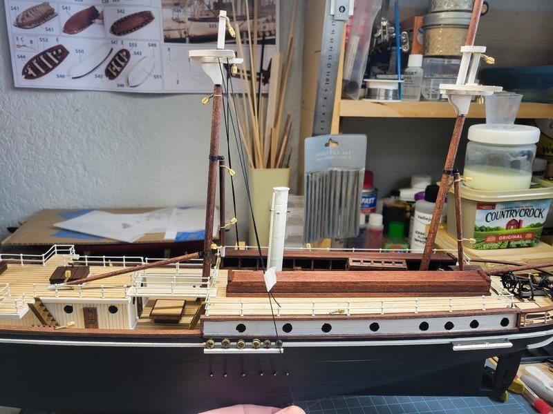
Hi folks, thanks for the likes and checking in. I completed the mizzen mast deadeyes and went ahead and ran the shrouds. I don't have a belay pin rack created for the main mast yet, so until I do, I can't install the shrouds.
The structures on the mizz have been glued down (minus the smoke stack, it'll be nice to remove it during rigging.) The two smaller funnels aren't installed yet for the same reason: they can be installed later and less prone to being knocked around.
I was a bit over shrouds and deadeyes by this point and was waiting on glue to dry for the main mast belay pin rack. I wanted to start figuring out ratlines, or more historically correct, some sort of bar across the shrouds. Several months ago when this came up in discussion I naively thought it should be simple to tie a 0.5mm brass rod (blackened) across them using a clove hitch, or overhand knot, or something. Turns out after spending an hour battling the top sheerpole I decided it's entirely too much trouble than it's worth (to me, anyway). Not only was there immense difficulty in getting the rod tied to the shrouds, but cutting, blackening, sorting, and managing them all before even tying seemed a bit too much.
So, I grabbed some 0.3mm black rope I made and tied a bunch of clove hitches.
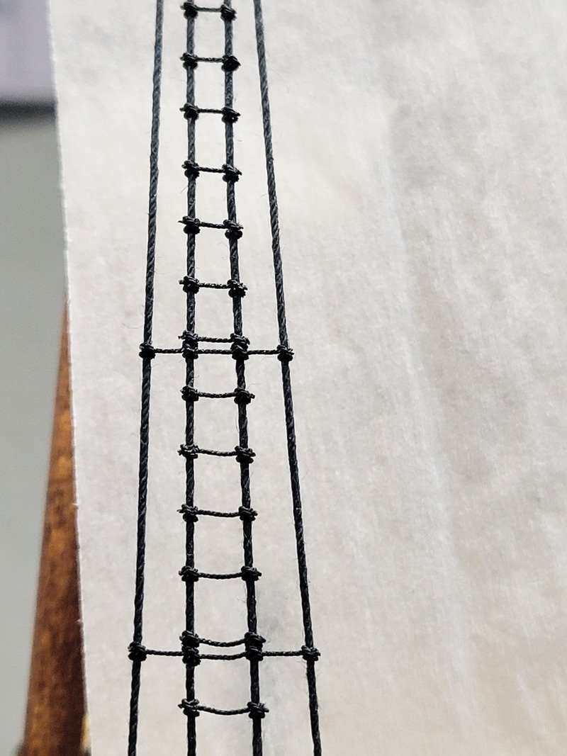
Each knot gets a touch of thin CA applied through a needle applicator. I really like the effect these make, and had I straightened the rung out more, it'd pass for a bar going across I'd say. I still really like it, so I'll do the same for the remaining 5.
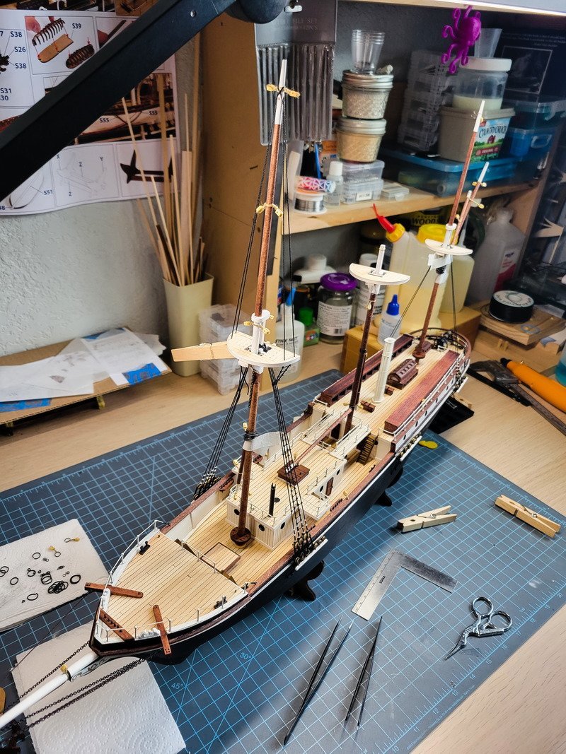
Finally an overall shot of things.
-
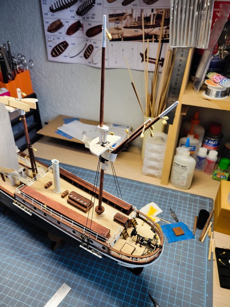
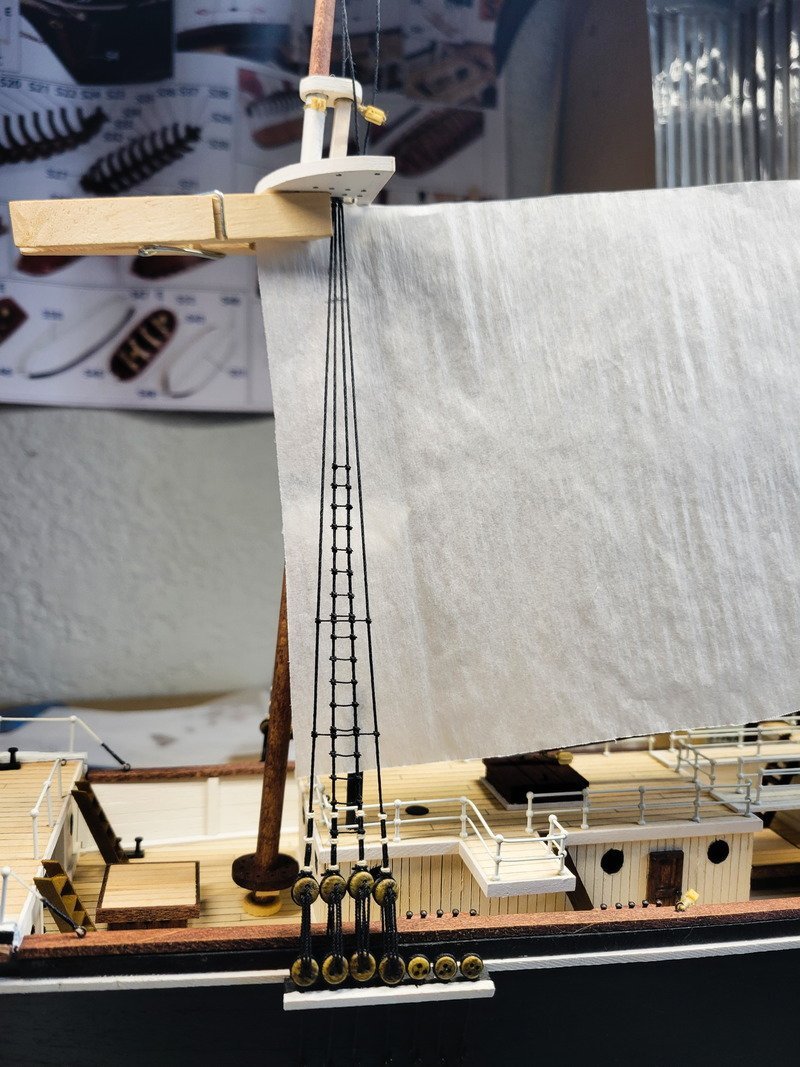
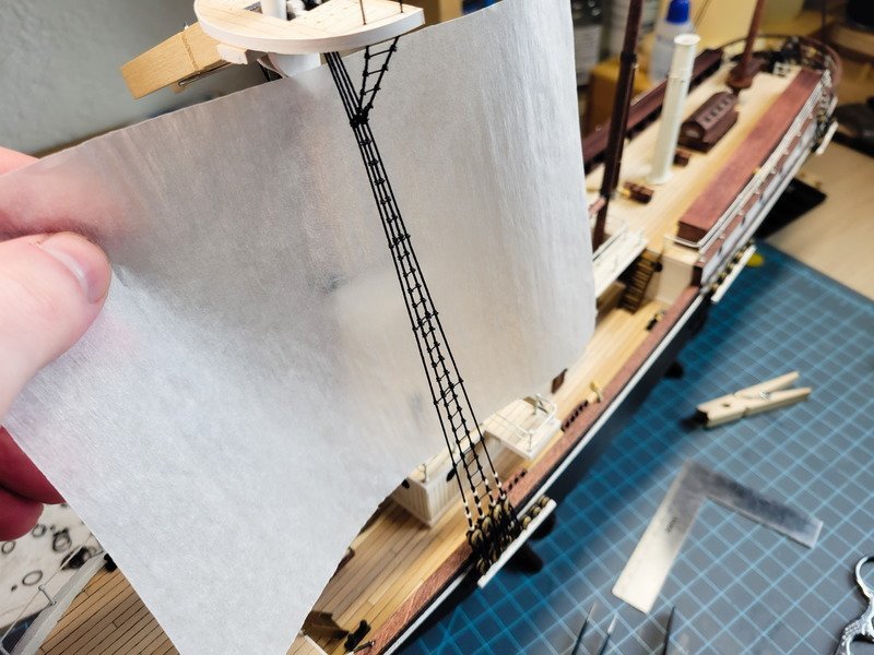
Hi everyone, thanks for the likes! I've finished up the square sails and can begin attaching them to the yards.
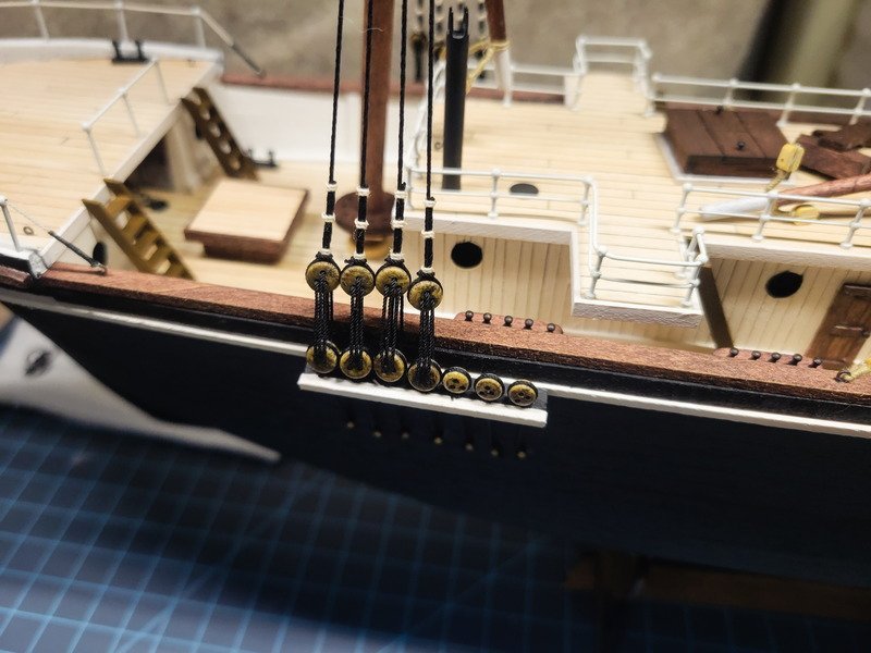
However, before that, I made a decision on the deadeyes. I have been avoiding making more since the first batch many months ago, and realized there's no reason to go that route when much easier options exist. I ended up using an Amati black rope. It's about 0.6mm, and best of all, doesn't look like rope. It almost looks like it's waxed, but it's not. The point is, from behind a display case, it'll look exactly like blackened iron.
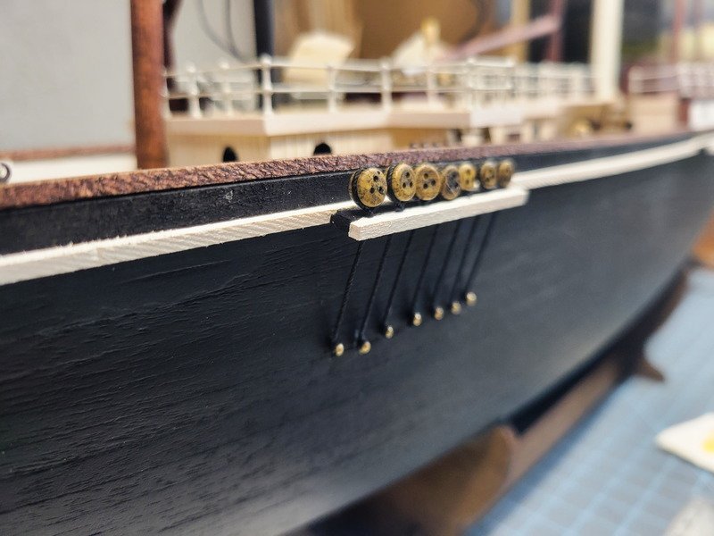
Yes: the deadeyes are upside down. Sadly, I didn't catch this until I had completed both sides for the fore mast. The deadeye is only seized by 2mm or less so I used a dot of thin CA once it's in the right place. It's impossible to twist the deadeyes right way around. It's also impossible to remove it, as the CA soaked into the rope and also the wood. I don't mind this, the main and mizzen mast will be corrected. It's a detail only I will know about in the end anyway. The brass nails will be painted black once all of them are done.
To measure the correct angle I rigged (taped) two temporary shrouds and marked the way it laid over the channels.
The deadeyes take time and after doing some last night and more this morning I wanted to get some rigging done. Over the last few days I've been racking my brain to figure out if there's any reason not to start bending the shrouds and I haven't been able to think of one. I decided not to sew on the fore gaffsail robbands because the gaff can hinge and move around, so if I really can't get to it once it's time, I can rotate it to in front of the mast and access it that way.
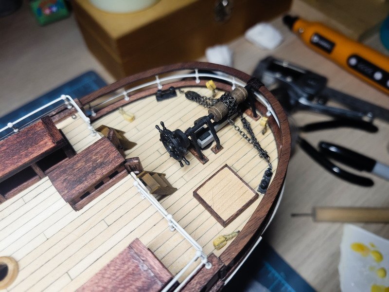
Before gluing in the mast I installed the 6 blackened brass rings for the gaffsail and the pin rack. You can't see them, but there are cleats under the rail to make sure I got it level to the deck. (Many things still aren't glued to the deck yet, so please disregard the crooked skylight lol.)
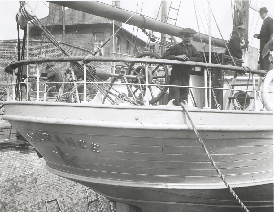
Next were the shrouds. I pulled up this pic for reference:
I remembered a while back in this log we discussed the shrouds being a braided cable. I didn't come up with a clever way to emulate this, but the same Amati rope I mentioned earlier will fit the bill because it doesn't look like rope. Or rather, it doesn't look as much like rope as scale rope does. I loosely measured the shrouds and seized them on the machine.
The two-piece mast really shined here. I didn't get any in-progress pics, but I finished up the lower shrouds on the fore mast. I was in the zone and installed another one for the smaller deadeyes, but then decided to check the plan first. Yeap, those are stays, let's remove that shroud hah.
I bumped the chimney's rain protector, opps. That'll be glued back later.
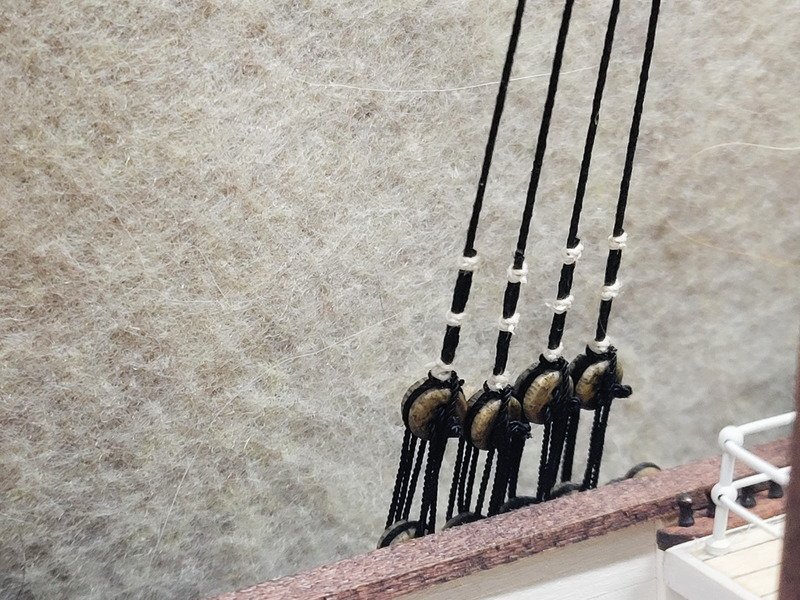
I really like the look of the rope lanyards, and then the shroud isn't as defined. The white thread is more of an egg shell color as well, which adds to it not being so bright and "new". Thanks for stopping in!
- Tomculb, iMustBeCrazy, HakeZou and 3 others
-
 6
6
-
A short update with not a whole lot to talk about, the gaffs are complete and installed. They're all loose so can be removed, and will be removed when installing the sails.
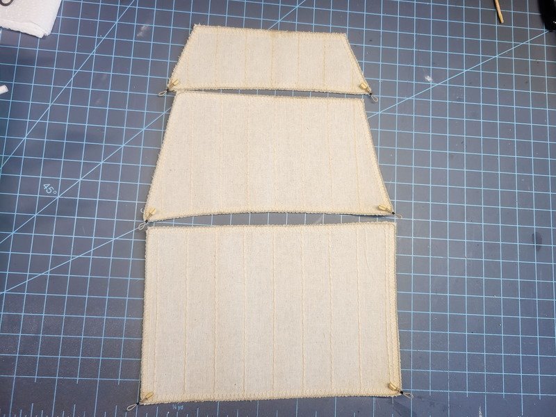
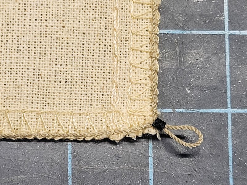
Speaking of the sails, I started checking out the connections needed to actually rig them. After viewing a few logs, and referring to Ship Modelling Simplified, I decided to sew a rope around the perimeter of the sails. This way I can include two beckets at the bottom of the sails for the sheets and clewlines. To accomplish this I already knew I didn't want to glue the rope first because it'll stiffen the sail. I could use fabric glue, but I don't have any. Instead I used my bench pin and clamped the rope on top of the sail, taut.
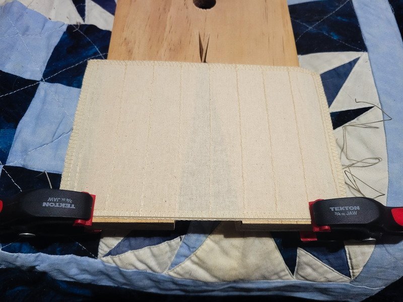
This way I could do a running stitch with a 1.5mm - 2mm gap. It took much longer than I anticipated, and there are a lot of sails to go. This will just be done in stages, and be completed over time.
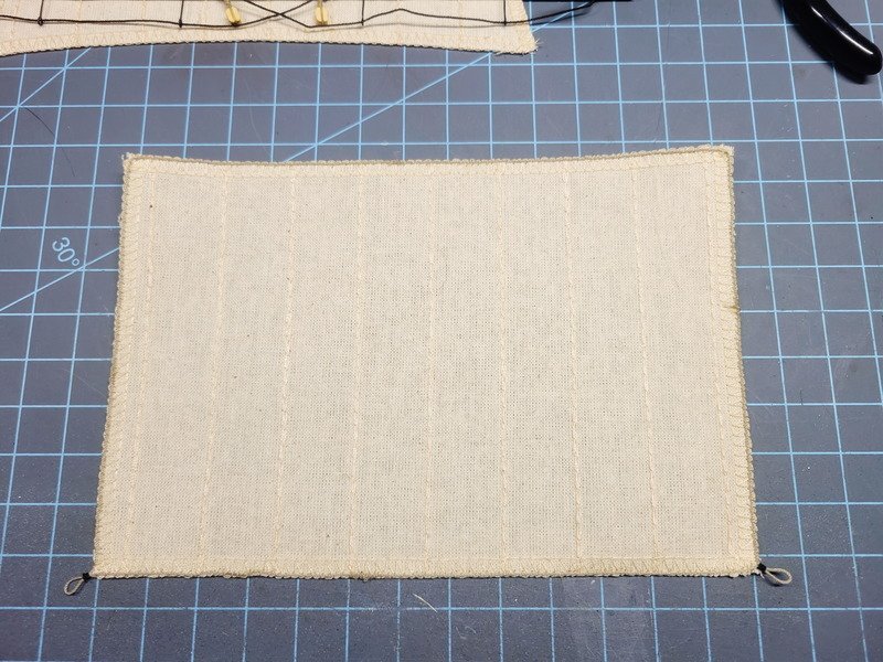
And close-up of the becket and stitching.
Tedious, but worth it. We'll see if I feel the same way after doing all the sails!
Thanks for stopping in!
-
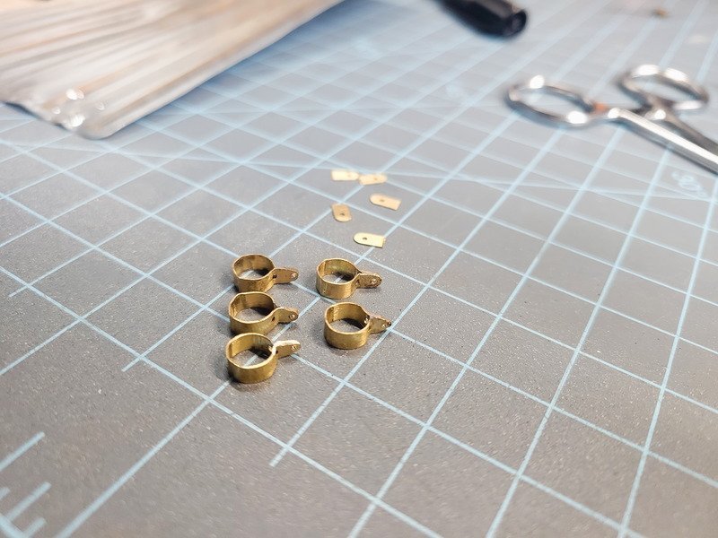
Hi everyone. I've been pondering the gaff connections over the last few days and have tried a few different things. They didn't work, needless to say. Just this morning, however, I happily came across some extra model ships bits that hadn't been migrated to my desk yet. Inside were exactly 5 brass strips from the first hull I completed, an AL San Francisco. These happen to be the exact size needed to fashion a working hinge.
Five ends of the strips were cut off to be inserted into the gaffs themselves. More on this further down.
The strips were flattened, and the bits on the right were ground to the half circle shape.
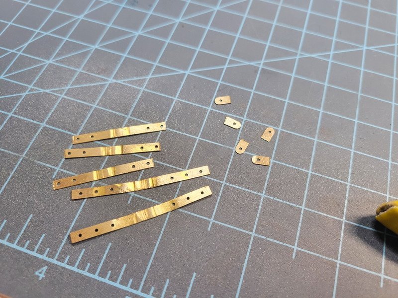
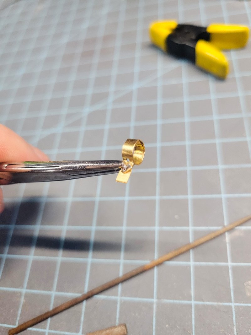
Using a cut-off dowel from when I tapered the masts, the strips were bent as tight against the dowel as possible. Even though the masts are tapered, all 5 of these are the same size. The taper the kit calls for is small enough the collars will still fit over the bottom of the mast and be tight enough around the top of the lower mast.
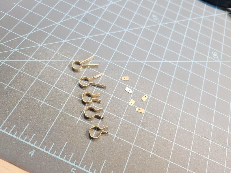
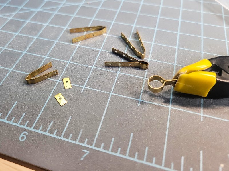
The collars got soldered together and the hinge was shaped and cleaned up. In the pic above you'll see there are pre-drilled holes along the strip. The hole closest to the collar is actually too far away from the mast. I cut all the collars at that hole, drilled new holes, then shaped on a bench grinder.
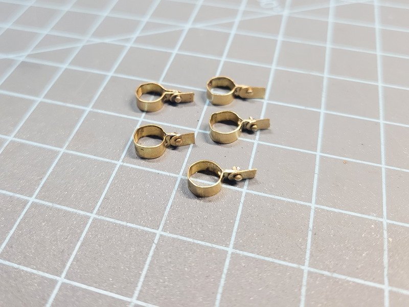
The pieces were cleaned up with a soft wire wheel, for better blackening later. I used the nails that came with the kit (for the hull planking) as the hinge. Non-serrated hemostats were used to clamp it all together, and a tiny dab of solder was placed on the back.
Hand files were used to clean up the solder, but the finished nail head is still easier on the eyes. These will all be oriented port side, which is the display side. The whole assembly was wire wheeled again.
The pieces were dropped in an acid solution, rinsed in water, then blackened. It only takes a minute or less and I rinse in clean water (not the same used to rinse the acid solution). After they're dry I used a Q-tip to buff the metal into a deep, dark, almost blue-black. Very satisfying to look at.
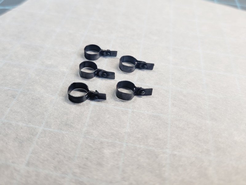
A slot was sawed into the back of all of the gaffs to accept the collars. I already had the sheave holes drilled on the two that need them, and totally disregarded those when sawing and gluing in the collar. Luckily I used wood glue instead of CA so I could remove it, saw the correct slot, and re-glue and insert.
They hinge, and they slide. Super neat. I could glue the collar to the mast, or just leave it and let the ropes do the work. We'll see how much I'll put up with it moving around when it comes to that time. The crane gaff and the lower one on the mizzen mast will be snug enough they won't move. The remaining upper three will slide a little bit, but still appear nice and snug on the model.
Thanks for taking a look!
-
On 2/24/2024 at 2:25 PM, Tomculb said:
I too was thinking of crafting some jaws and parrels, but after Keith's and Craig's input, I don't think I'll do that.
I agree and have been trying to come up with something, but haven't landed yet. Ideally I'd use brass strip and fashion a goose neck and blacken it. I tried to cut strips (again) from brass sheet I have and it's not straight enough. I do have copper tape that I've been thinking of using, but not sure how the connection would look. Still at the drawing board phase on this one.
----------------------------------------------------------------------------------------------------------------------------------------
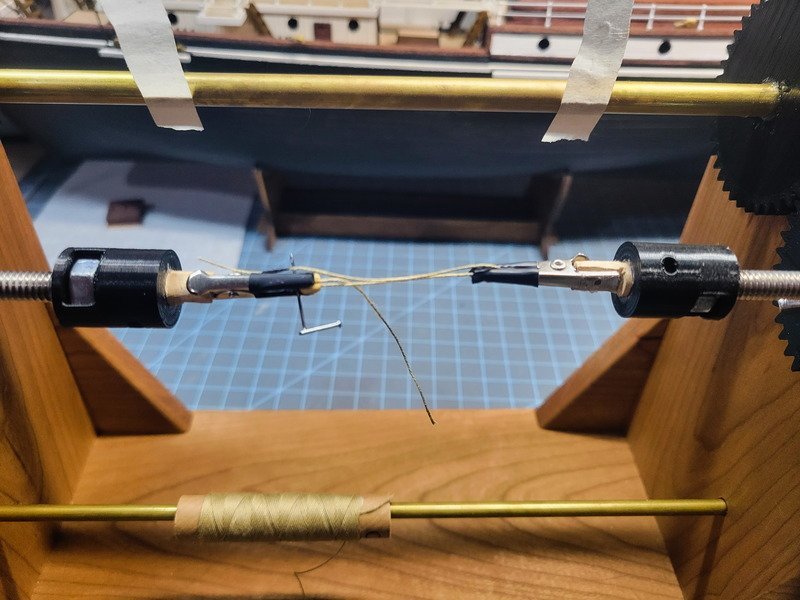
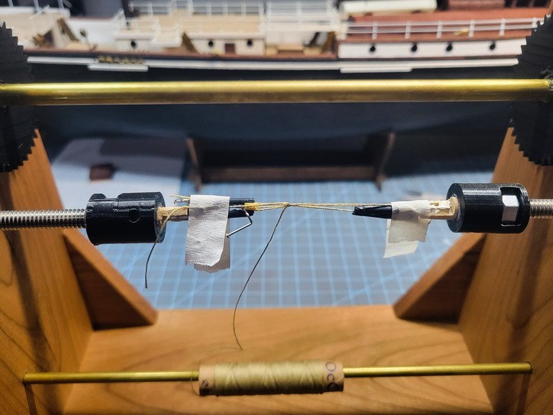
While working on the yards I needed to consult my log to figure out how I seized the blocks. I ended up tweaking this procedure and fashioned a new accessory for the seizing machine. Whether the blocks get seized around eyebolts, or yards, or gaffs, it's the same method and I ended up with extremely consistent results. Here's a pic guide on how I do this, so if I take another 4 month break I can remember how I did it!
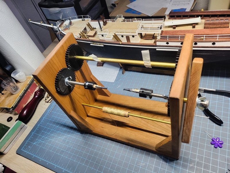
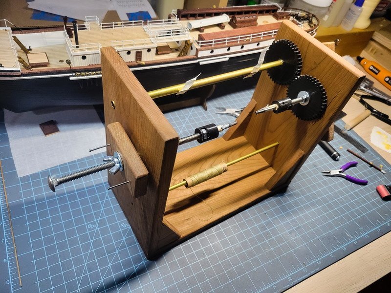
The carriage bolt on the left can be adjusted in or out to allow specific sizing between the alligator clips. I don't take credit for this idea...I saw it on this forum several months ago. I did however 3D print the black couplings between the bolt and the alligator clips. The idea here is the alligator clips can be removed and other attachments can be installed.
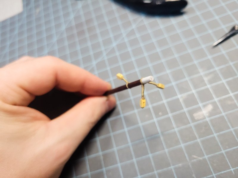
To begin I cut off around 10" of the same thread occre supplies with this kit. I glue a block to the thread about 1/3rd of the way down, and then fold the thread over and glue that side. If a becket is required, I insert a pin.
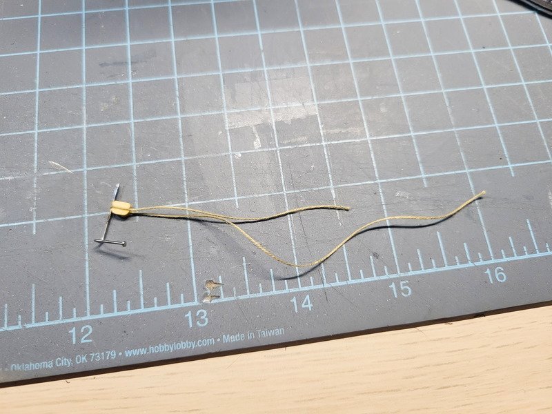
The longer side is marked with a sharpie and then the block is placed in one of the alligator clips. This thread can be pulled after wrapping to affix to yards or whatever. If an eyebolt is required, I thread it on now and that'll be inserted into the other clip.
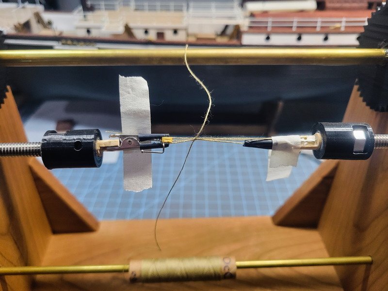
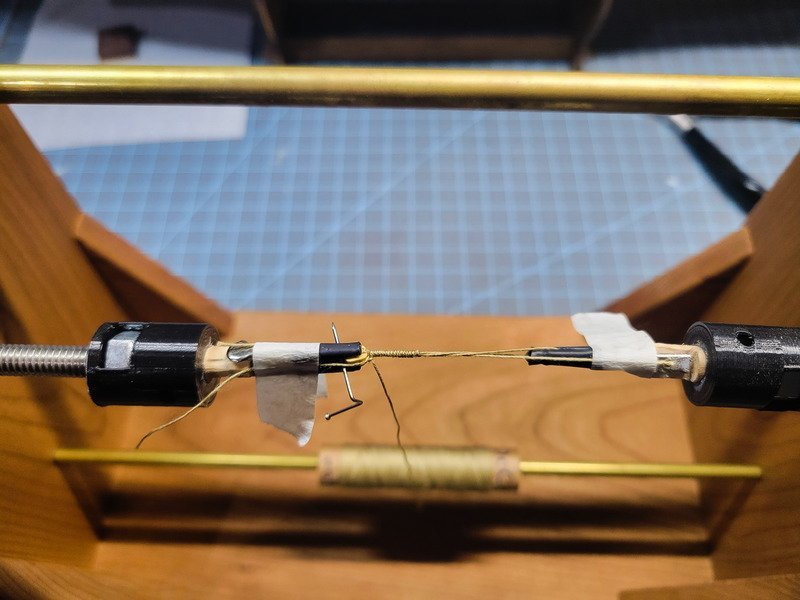
The marked thread is then taped back to the left alligator clip.
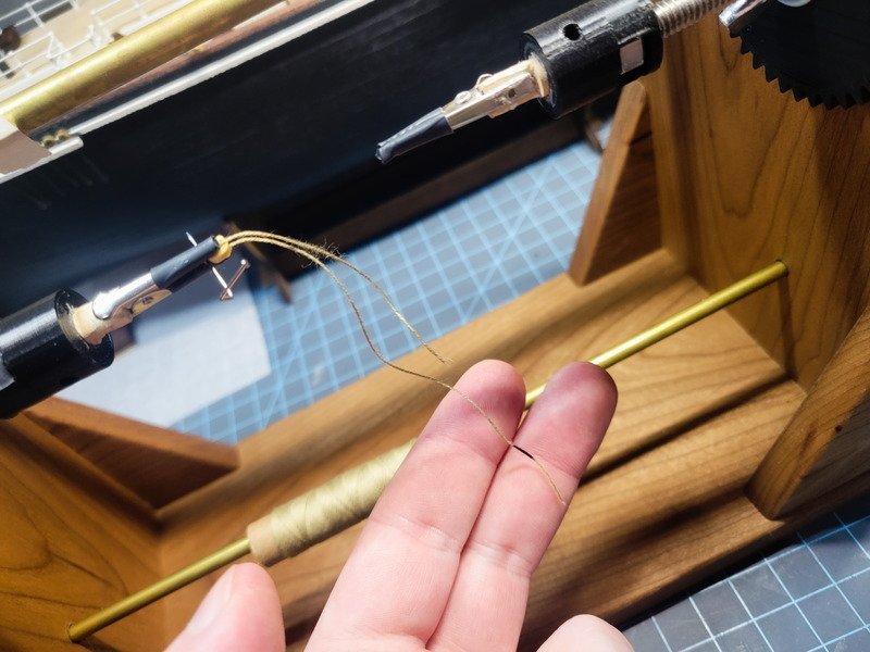
The loose ends are taped to the alligator clips to keep everything tight and out of the way. I then bring up the thread from the spool on the rod below, and tie an overhand knot. The loose end is taped to the left.
I'll hold tension on the thread being wrapped and rotate the handle. Since everything's held tight it winds up really fast. A half hitch is used to secure it under the block after being cut from the spool.
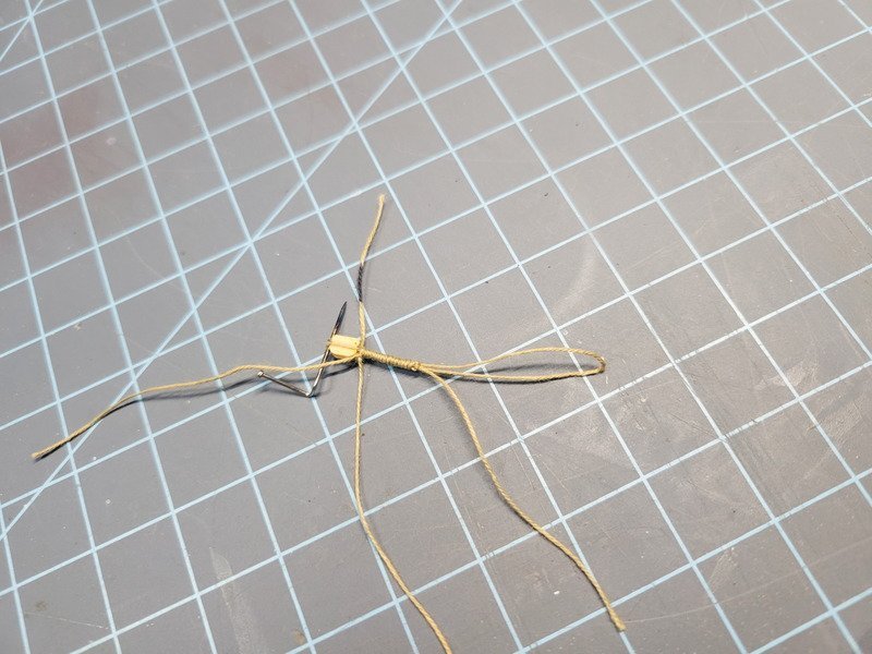
And here it is off of the machine. Notice the loop on the right, and the marked thread on the left. Pulling the thread will tighten the loop. This one doesn't have an eyebolt, but if it did I'd still pull that marked thread and it'll tighten the wrap to the block.
I finished up the final blocks on the aft deck.
And finally the skylight is complete. This is the 4th or 5th iteration of this structure, and while I'm not 100% happy with it, I'm more happy I'm done with it. Happy enough to call it done, anyway. Before anyone notices: no, there aren't any window holes. lol. Every one of these I built looked like it came from a Tim Burton movie with how crooked everything was, so I determined that's the limit of my modeling skills. For now lol.
I also noticed after scribing the roof there's a separation between the two hinged panels, and I have them butting up against each other. I'm happy with it, I'm happy to be done with it, so it'll stay that way. No problem.
Thanks for coming by!
-
-
21 hours ago, clearway said:
make the stick a bit longer abd thinner and it will be about close enough.
After looking at it the last few days I think you're right. It's glued together (but not to the deck) so I may adjust it, or I'll leave it.
21 hours ago, iMustBeCrazy said:2' tall in the middle, 4' x 4' square, 2 windows each side, hinged centre panel in the roof either side
Thanks Craig. That's what I came up with as well. Surprisingly I don't have stock small enough to just build it, and all 4 or 5 attempts I've made have had crooked cuts, not consistently measured, etc. Just doesn't look how I want it lol. One of these days it'll get built.
On this topic though I wanted to drop a link to a huge Endurance model I came across yesterday. In doing all my research several months ago when there was great discussion about the placement of this skylight and a hatch I never came across this. Of course, it's a subjective model created by someone (or someones), however, it shows the post-Buenos Aires configuration with the mizzen deck extended to the quarter deck house. Here's the link, click on 3D Tour in the top right. You have a full walk around of the 15' model. Again it's subjective though, because the stern deck is completely incorrect, along with the ratlines, no capstan, no area under the anchor deck, etc.
The point is this is the second model I've now found that shows a skylight and a hatch (here's a link to the first one). Where are the builders getting their information from to include them in this way?
Back on track I've finished up the yards for the foremast. I'm not happy with the foot ropes being kinked so much, but that was the last of my homemade rope anyway and new batches are going to be stored differently.
I also added some rope to the stern railing to hide the join.
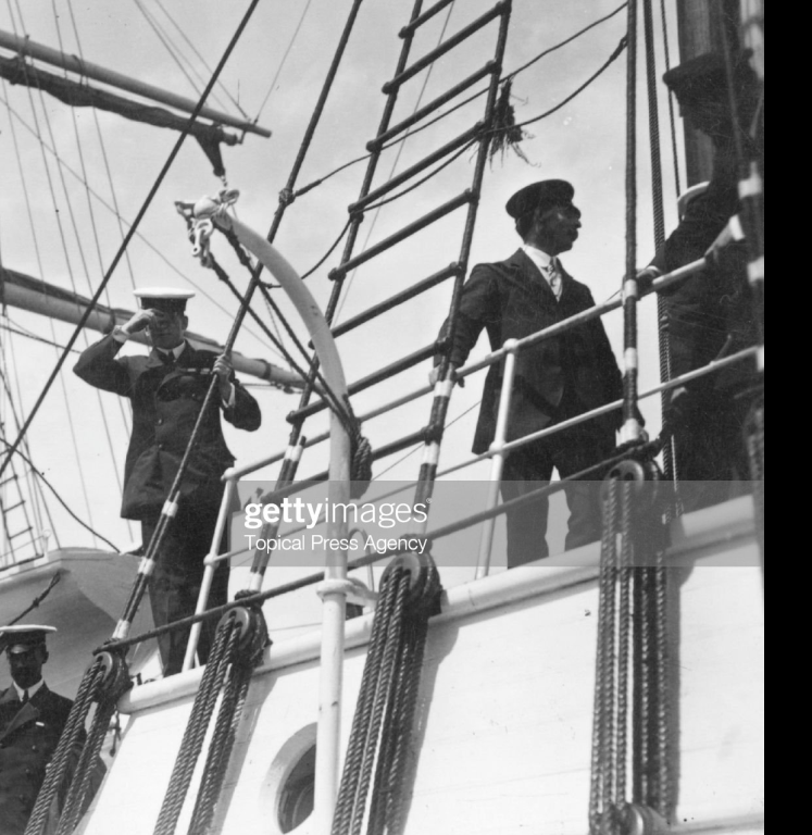
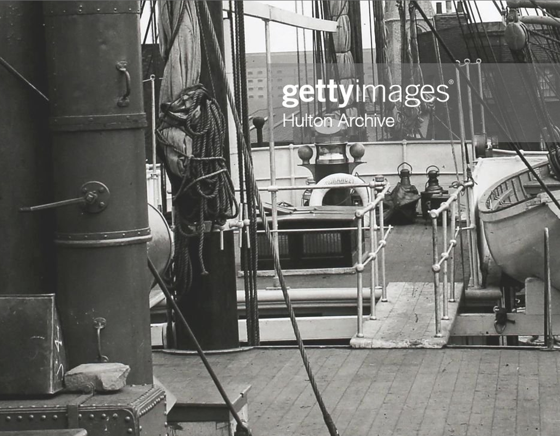
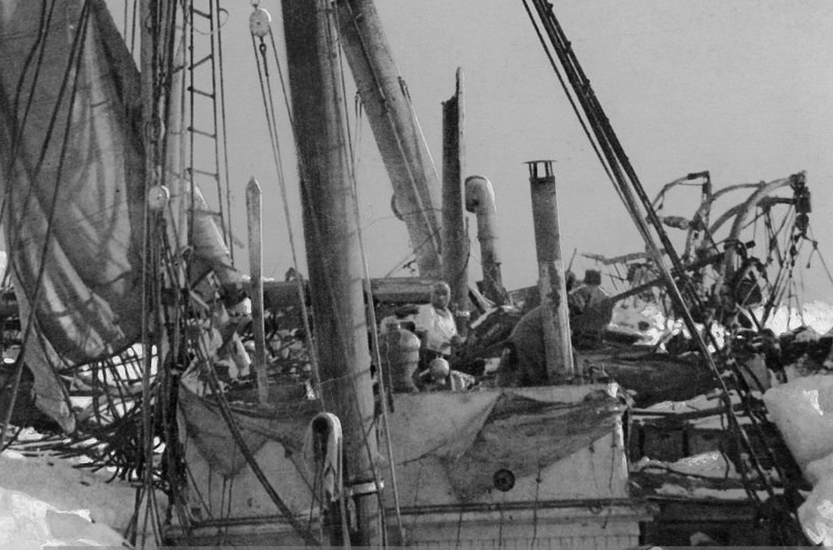
Lastly I've got a question for anyone. The kit would have me install the gaffs using an eyebolt on the masts, and Hakezou mentioned having issues during rigging because of this. With all of the images out there of Endurance, this is the closest I can find that shows the gaff connection.
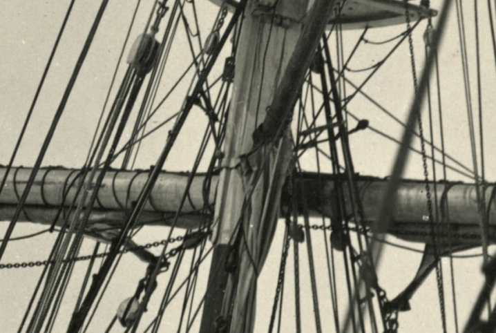
I don't see any parrels, or jaws for that matter. Here's a pic from Ship Modelling Simplified:
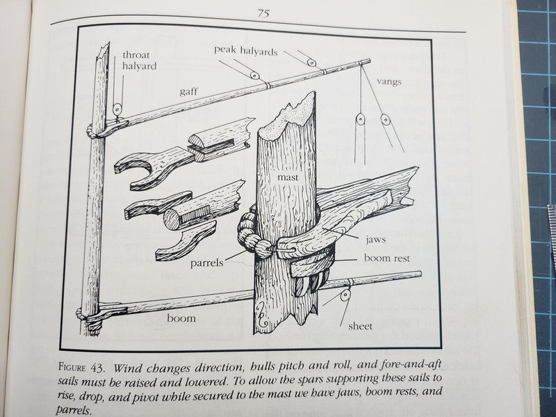
If I added parrels and jaws to the gaffs (minus the crane) would that be unrealistic, or out of period?
-
7 hours ago, iMustBeCrazy said:
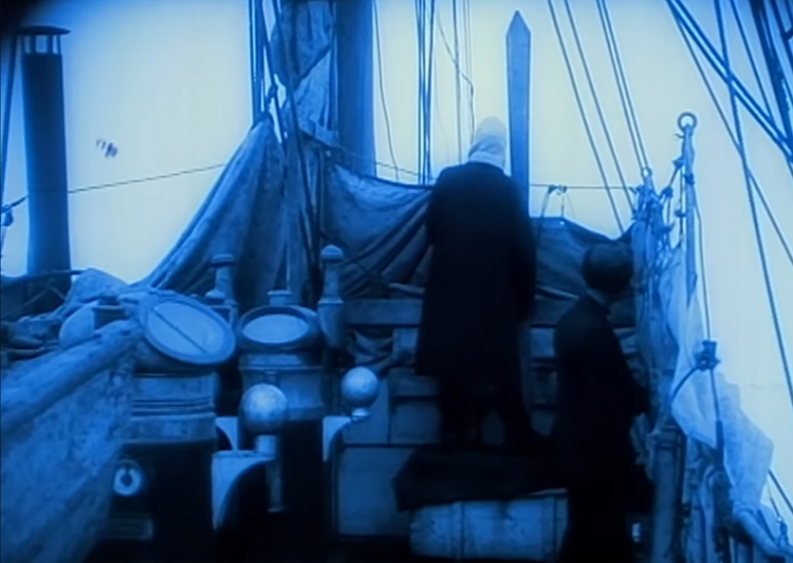
I think this is all I've got. The photo seems to confirm the sketch in that it shows the top glass is very steep (behind the guy's legs on the right).
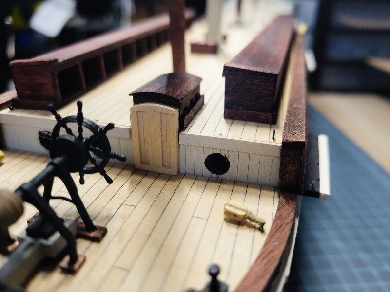
I'm afraid I don't know what you mean, Craig? The skylight on the mizzen deck is complete and I'm happy with that. I'm referring to the bridge deck, or "deck house" on the quarter deck. It's what I was calling the "Ritz" earlier in this build log. Here's a pic of it:
I believe the glass you're seeing behind the man's leg is due to an open window. Check out this post in my log, there's a screen grab of the wreckage video which shows the mizzen skylight really well.
-
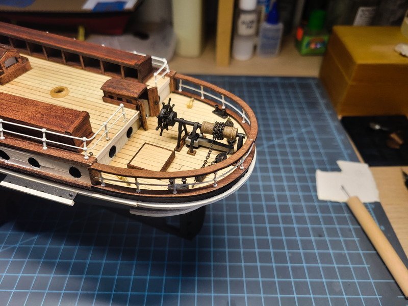
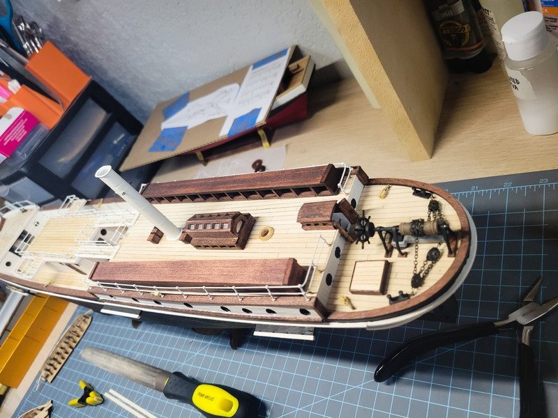
Hi everyone, thanks for the likes and comments. I believe the skylight on top of the quarterdeck house is the last structure that needs scratch built. I've sat down and pondered it several times, but can't come up with something I move forward with. Eventually that'll get built.
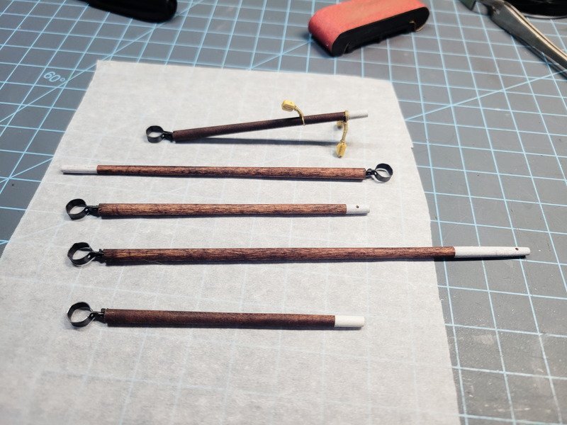
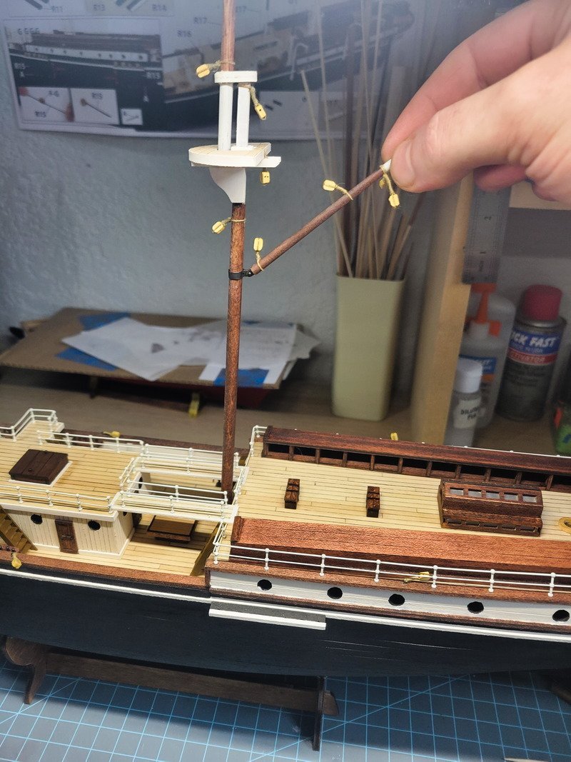
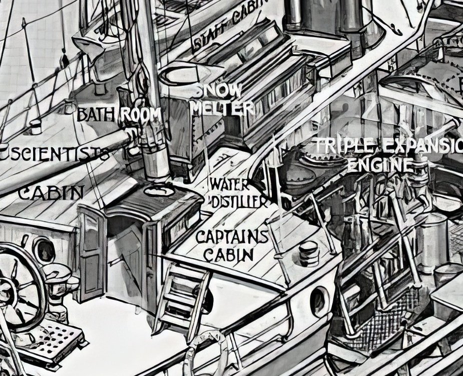
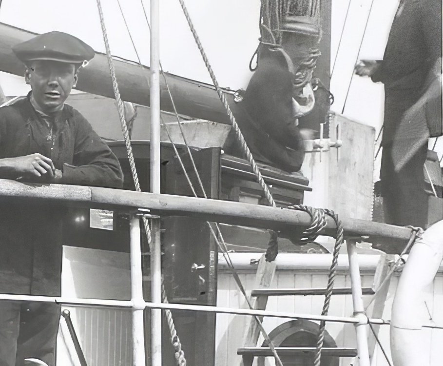
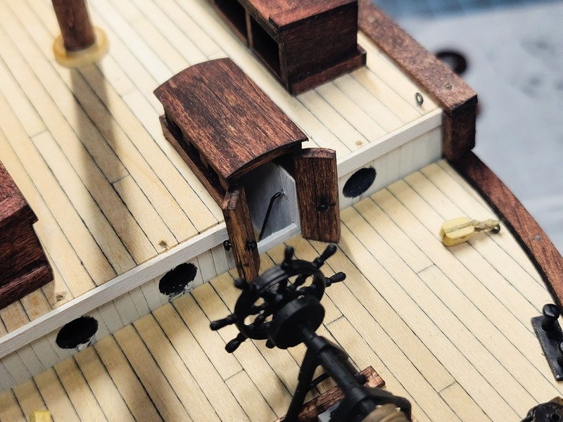
Something much easier though is the telegraph. It's not part of the kit, but can be seen very briefly in one of the youtube vids. Here are two stills showing it:
Not a whole lot to go off of, I did notice the arrow itself could be just about as tall as the guy operating it. In 1:70 that's just over 25mm, so that's the length. It also appears the arrow is about as tall as the galley stove pipe, so I eyeballed something to hold it and stuck a nail through it. Then just glued it to a chest.
The angle of this pic isn't very flattering, but I like the detail it adds.
Next is finishing the foremast yards, and hopefully figuring out a skylight soon. Thanks for reading!
-
Good point Keith, but I haven't even considered putting them in. I think I'll have all of the ship's boats outboard, so I wouldn't need to put the skid beams in right?
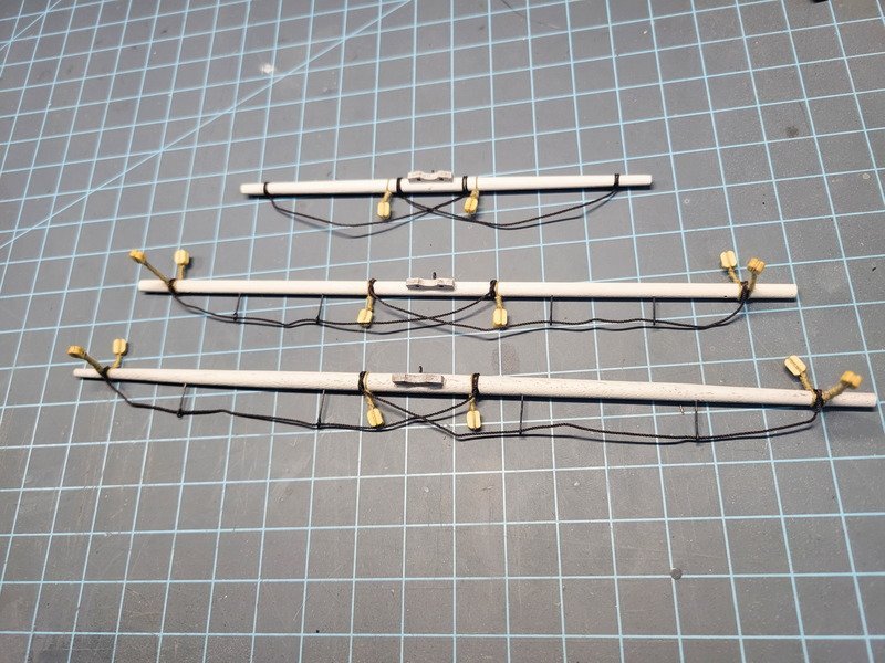
A bit of progress which took a ton of time are the yards for the fore mast. Not much to say about them as they're built to the kit's direction. The upper and lower topsail are complete, with the foresail still needing finished. I'll fashion the wire that goes around the mast once it gets closer to time to putting them on permanently.
The foot rope is 0.5mm brown (guterman 696) made from the rope walk. It was stored on a flat bobbin and wound up which left kinks. I'll be considering a new storage situation, probably just keeping the ropes in circular wraps. Anyway, once they're hanging from the mast I can try hanging some light weight from them to shape them, and using diluted pva to get them to hold shape.
The real ship had a roller on the lower topsail, and I decided not to include it so as not to add to the complexity. Next time!
Thanks for stopping by!
-
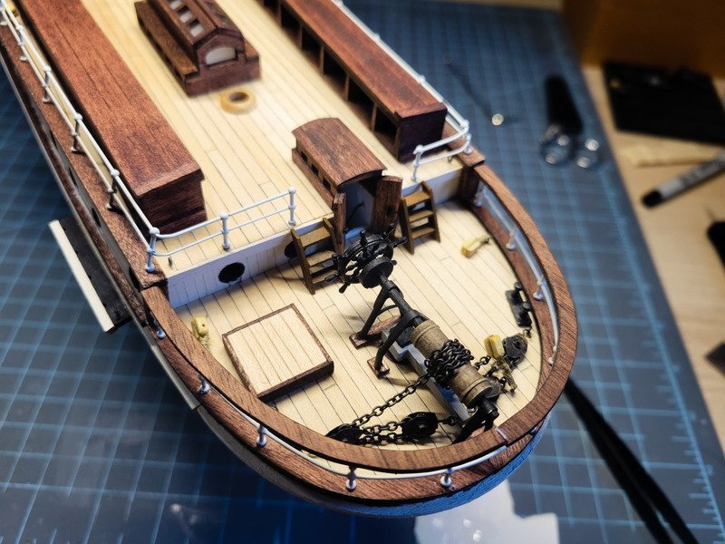
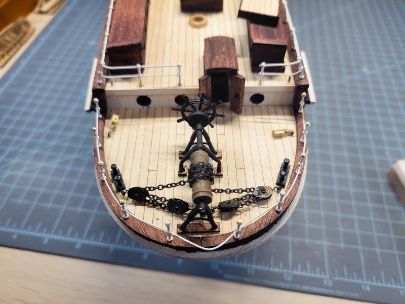
Another update for the day, the quarter deck pin racks are complete. I would've done this a long time ago, but Occre shows two different layouts, so I needed to get the rigging plan mostly finalized. Thankfully @HakeZou still had his excel sheet and shared it, so I have an extremely solid foundation to rig this model. This will be my first full rig, so I'm using it to learn the ropes (heh) and all credit to HakeZou for the changes from the "plans".
That being said, there are 4 racks of 5 pins installed. The pins are blackened 8mm brass pins, not the ones that came from the kit.
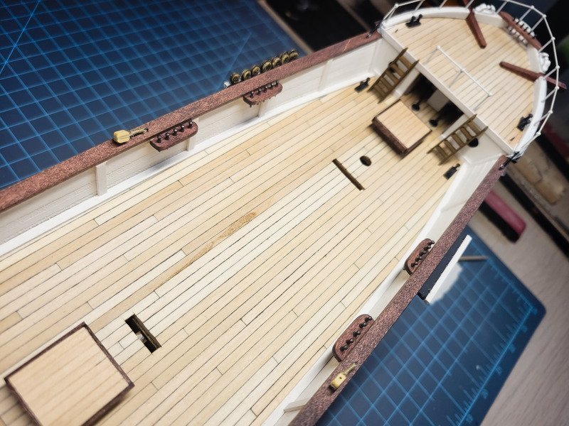
With the racks finally installed I trimmed out the bottom of the deck house and glued it in. The ladders were also glued in after this pic.
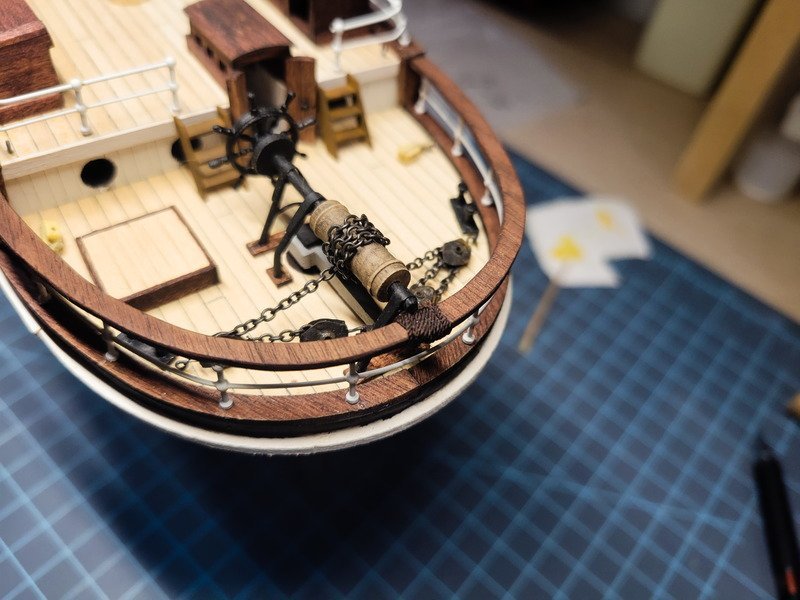
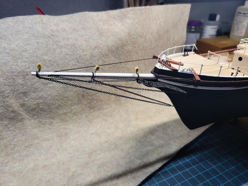
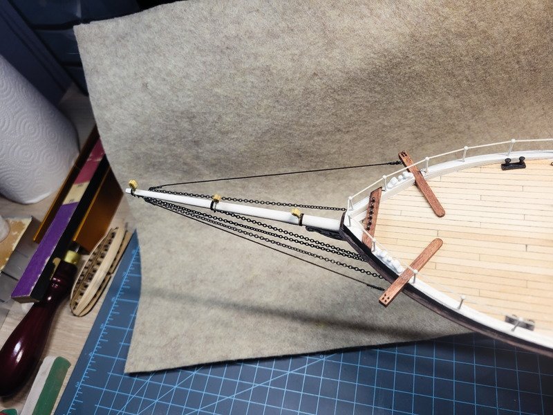
In the swing of things now I wanted to tackle the bowsprit. Since every eyebolt on this ship is soldered shut, I needed to attach the chain by bending links. I spent probably 40 minutes on this task before finally just using black thread instead. It looks more or less like a link in a chain, and won't be noticeable in the grand scheme of things.
Thanks for reading!
-
Thanks Keith and Tom! And no worries at all Tom about your post! It's been nice to get back into thinking about the Endurance and working on her again. I don't think it'll be an every day thing as before, but it's always an ebb and flow with progress with these models.
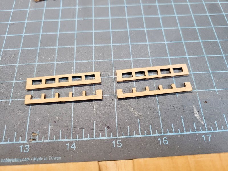
Speaking of progress I've completed all of her ladders. The kit supplies a brass PE sheet and many months ago I attempted to solder the two smallest ladders together. It didn't work out (I was later guided towards gluing them, which would have worked much better.) Alas, the two small ladders had entirely too much solder on them to even try to clean up so I scratch built all of them anyway. This took a lot longer than I wanted it to. Next time, I'll build a small jig to make sure the angles are correct, as these leave a little to be desired as far as being square.
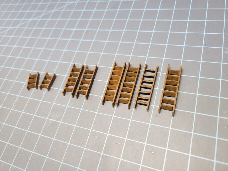
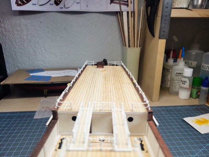
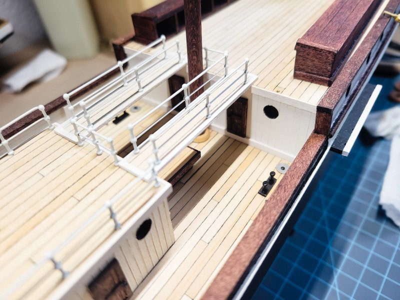
With the stern companionway doors open like I've represented them, the stock ladders would have been too wide and ended up well passed the inboard stanchion, so scratch ladders would have needed to be built anyway.
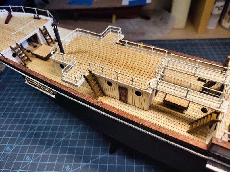
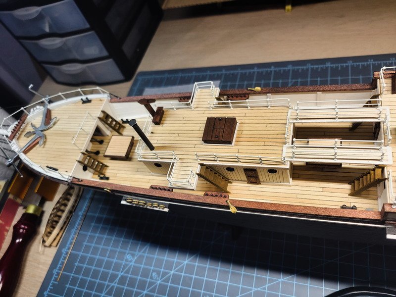
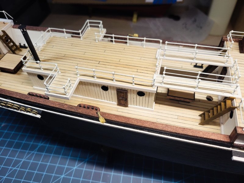
Note: Nothing on the mizzen deck is glued in yet. Things probably aren't in the correct position.
The deck house (formally referred to as the Ritz) on the quarter deck is still not glued in, as I need to add trim to the bottom of it. Although I haven't decided if I'm going to add that trim with the deck house off of the model, or attempt to do it while it's on. Problem for another day.
I mention this though because the gangways are not glued in, and will not be glued in until rigging is more or less complete. This was done on purpose because the real ship's gangways were removable. Once she started her journey to the pole that section was entirely decked over anyway. Going back to my original motivation for building this ship, I honed in on the gangways as being a nice detail I've never seen before, which is why I'm representing them. Making them removable (as opposed to Occre having them permanently attached to the roof) not only is more realistic, but makes rigging a breeze. I hope, anyway.
Lastly I wanted to leave a picture of my current time spent on this model. For anyone that doesn't know, I track my tasks in an excel sheet so I can definitely say "the decks took this long. The rigging took this long." etc.
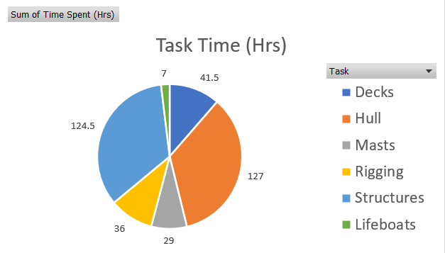
Total time spent (so far): 365 hours.
Thanks for stopping in!
-
29 minutes ago, Tomculb said:
Thanks Josh. I wish you were still posting your log, showing me the way 😃. I assume you've realized that available time is finite, and as between writing and building, you choose to build. Good choice.
I only wish that second part were true, sadly. I haven't been in a position to work on her until literally two days ago haha. It took almost an hour just getting all the cat hair off the decks!
If I may, when posting links to specific posts, did you know you could link directly to a post number, like this (Post #68)? At the top of each post on the right hand side you'll see the post number:
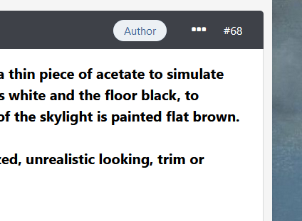
You can right click that "#68" and "Copy Link" then use that as the address when you embed the link like normal. I only mention this because you linked to my log and I needed a refresher on what we were talking about at the time lol!
I really like your interpretation of the aft companionway. One thing so basic I actually struggle with is getting those perfect 90* corners like you have on the door. Well done!
-
-
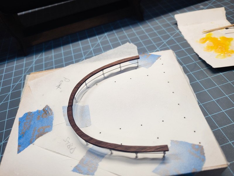
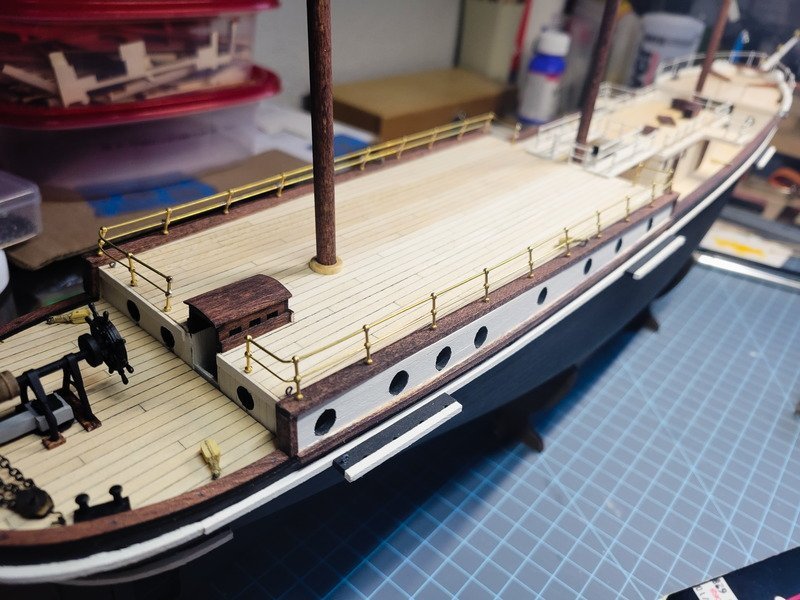
Hi folks, it's been a few months since my last update and today the stars finally aligned to make some progress with Endurance. Coming off of the last update I really wanted to fix and finally be done with the aft railings. I removed the stanchions from the rail and ended up needing to recycle a few. I dunked them in acetone for a bit then used a rotary tool to easily remove the paint.
This time, I installed the stanchions into the existing holes and started running the 0.7mm brass rail through the middle ball. I'm letting this one go, but had I opened up my log and read my last few updates, I would have reminded myself that the middle rail needed to be 0.5mm, not 0.7mm. I realized this after the fact, and am totally fine with it. With the rail installed I used thin CA to glue it up, then removed it and airbrushed it. Reinstalled, I could size up the walnut cap rail, make some adjustments, and glue it in.
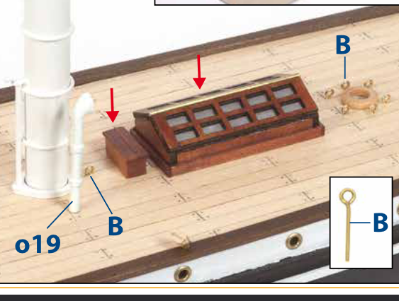
Where the two cap rails meet at the aft-most point I'm planning on a rope hank to cover the butt joint. However, there's an eyebolt with a block that's supposed to go into the bottom rail. See here (don't mind the red arrows):
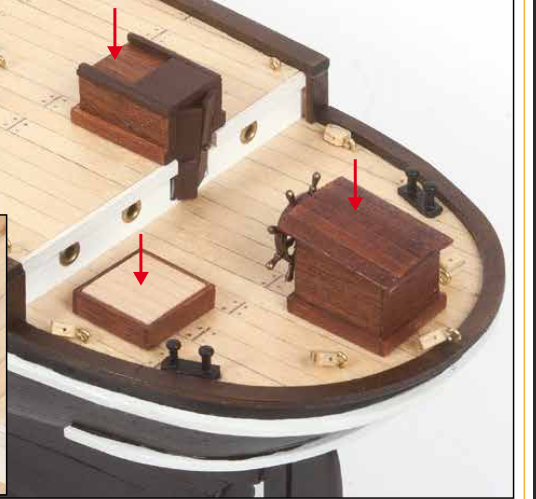
Originally I was just going to extend the block from the eyebolt. But after further inspection of her pics there doesn't appear to be a block there at all.
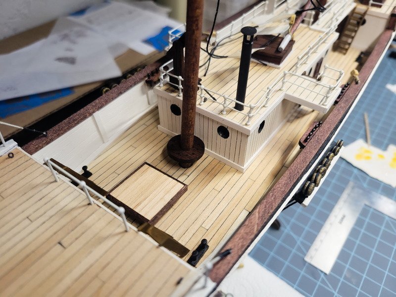
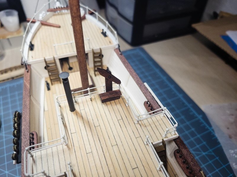
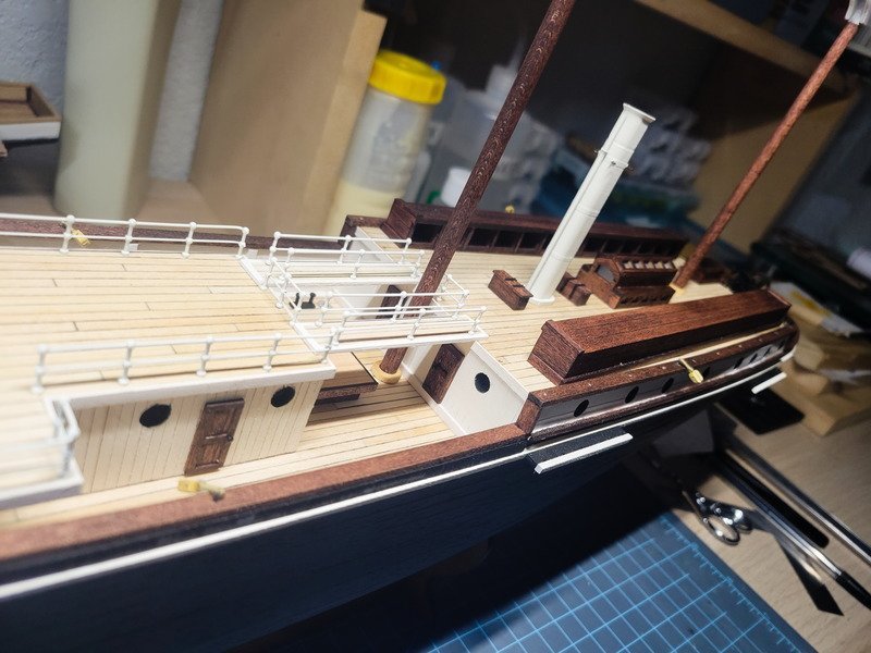
It's for the flag, so that'll be a problem for rigging Josh to solve. Since I didn't open my log and I didn't have a plan for what to do next, I decided to tackle the stove pipe coming from the quarter deck house. This isn't in the kit, but is visible even in her wreckage pictures. This time I did open my log, because I remember clearway providing the measurements he used (thank you again!).
First was figuring out a rain guard. I selected some rather thin brass sheet and used a paper hole punch to get a perfect circle. This circle ended up being (more or less) exactly to scale against the 4mm brass tube being used.
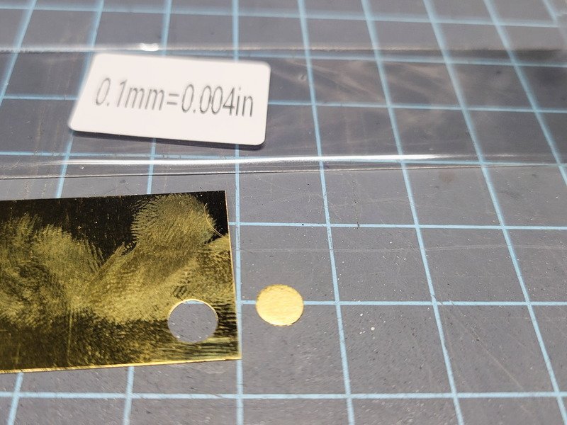
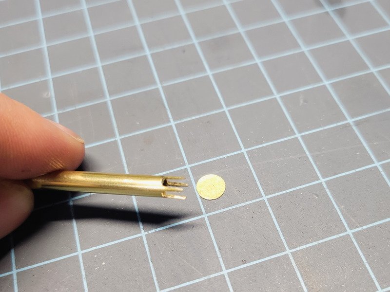
A rotary tool was used to cut 5mm down the middle, then rotate 90* and cut down again. Hand files cleaned it all up. I decided against attempting to solder them together, so next was blackening.
I used some steel wool to clean up both parts. For the tube, this was not enough. I ran it through the process and kept getting spots that wouldn't take the blackening solution. I ended up sanding the entire thing (should have been done first!) in 220, 400, then steel wool. It came out extremely smooth and consistent. I then used a Q-tip to softly buff away the extra crud on the surface and polish it.
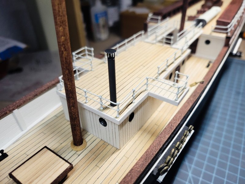
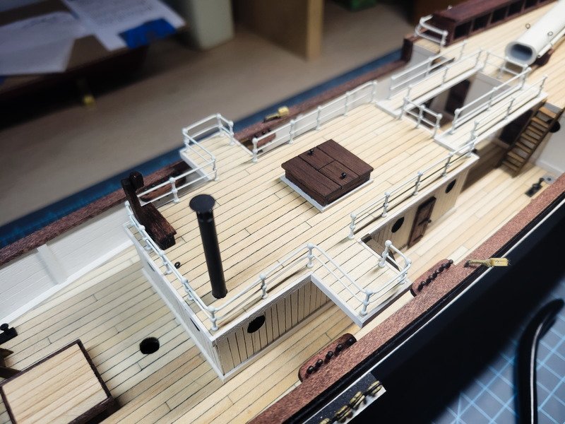
I was so impressed that I was able to get the splotchiness out of it I drilled a 4mm hole into the deck and inserted the stove pipe. It's the same as clearway's: 35mm above the deck, 5mm slits down from the rain stop. I added 10mm below deck, so mine is 45mm total. I glued it in.
THEN I looked back at the reference photos.
The darn thing is half white. In London, it's all white. (Bit hard to see, but it's in front of the main mast.)

Dang. The railings are already glued in to the quarter deck house, so without removing the pipe (it's glued in) painting is out of the question. That's alright with me though, I like the blued metal look. The pic makes it seem warmer than it is, it's a deep dark slightly blue black color.
Thanks for stopping in!
-
On 9/28/2023 at 11:20 AM, clearway said:
I always use superglue on my handrails
This is definitely the way. I'm not sure why I was holding myself to soldering them, but that ship has sailed, so to speak.
--------------------------------------------------
Small update to show not everything can be rainbows and daisies. I took a few days off from the bench and came back when I received some 1.8 mm walnut sheet. I ordered this specifically to cut out a handrail for the aft deck, as seen in pics. I didn't want to use 0.7mm wire painted white like the bridge and mizzen deck. I traced the aft deck cap from the laser sheet and cut the same pieces using a jeweler's saw. The walnut gets extremely fragile towards the end perpendicular to the grain because it's not ply. Then stained red mahogany.
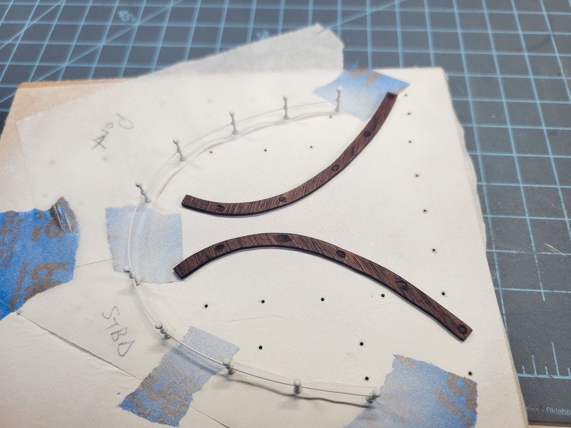
Here's the mistake. I glued 90% of the stuff to the aft deck that needs to be there which left very little room to try and use tracing paper to transfer the stanchion locations. Another issue is pencil lead on red mahogany stain is almost imperceptible once you lay tracing paper over it (heh, who knew?). So keep in mind the marks are not accurate, but somewhat close.
I glued (finally learned my lesson!) 0.5mm brass rod through the middle balls and used a cheap engraver to make cups under the hand rail. I didn't want to just glue the rail to the balls. I thought about cutting the top ball off entirely, but decided against because the middle rod won't be in the middle anymore after drilling holes into the rail. Sure, you could butt joint it I suppose, but it'd be awfully delicate for a lot more work to yet be done.
Success, it actually worked! I'm surprised at how well thin CA holds, as I couldn't move the brass wire at all. I'm not sure why I thought gluing the hand rail on would negate the pent-up force in the rod from the bend, but here we are. Once I removed it from the jig, the wire promptly went back to straight, causing all stanchions to become unglued. Right on, I'll just re-glue the rail and move on.
Well, back to the drawing board! I don't really see a way to solidly fix this, so I'll chalk it up to another railing failure. So, what can be done to avoid this? Well, marking and transferring the stanchion hole locations as soon as those caps were installed would be a good idea. With nothing to get in the way, there's no worry of messing up the transfer. Just don't lose the tracing paper.
With all the stuff installed I suppose I have two ways out. I can use the laser sprue to trace the exact shape on to tracing paper and use that, since it'll lay down completely flat. Then drill new holes, etc. I could also install new stanchions in-situ, glue new rod, then remove and paint. I'm leaning towards that, since the CA really holds, but I'll leave it for another session.
Thanks for reading!
-
Hi folks. I received the replacement stanchions (take two) and set up a building board. I detailed this with the quarterdeck house (bridge) update. It's hard to tell, but after each 90* angle, the stanchions needed to be countersunk 2mm because the main run is installed into the trim. The remaining get installed into the deck, 2mm below. Had I not accounted for this, the brass rod would be the wrong length and it wouldn't fit.
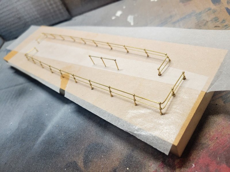
There's no soldering, even the ends. The paint was airbrushed on, then a coat of matte finish. Left to dry a few hours and installation was an absolute breeze. There's very minimal touch-up which still needs to happen. This method of installation as opposed to soldering it all together works best for me. I suspect the solder I'm using is too high of a temp for the liquid flux I have. It boils before it has a chance to wick the solder places.
I'm really happy with the inboard angle. As mentioned I still need to touch them up.
I was cruising through the manual to make a list of what's left before rigging can be seriously considered. I'll admit, I genuinely forgot there were 4 more boats to build! I know they don't need to be done before rigging, but I found it funny this particular kit has 5 vessels and I forgot about 4 of them.
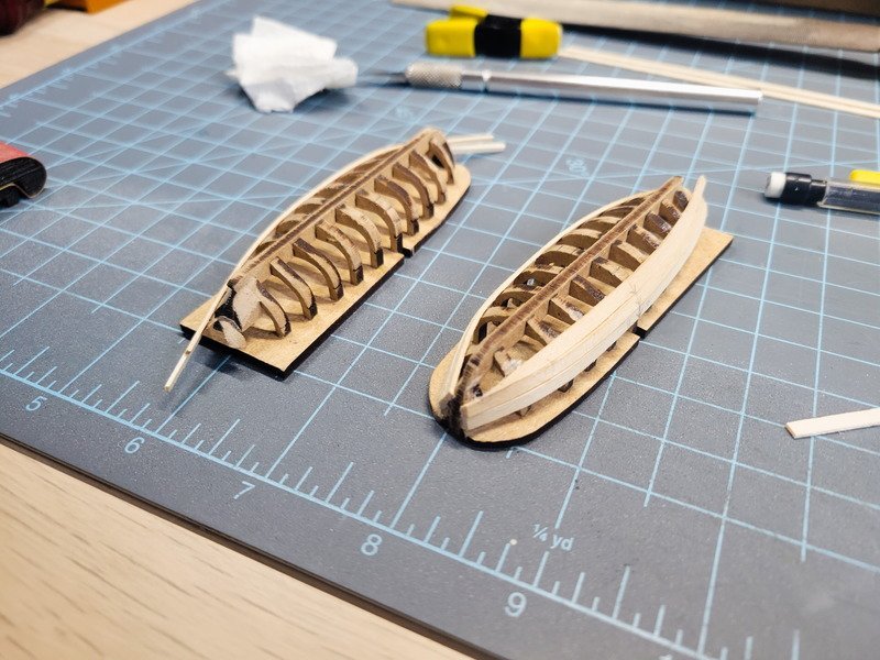
Starting with the 2 bigger boats setting up the frames went smoothly. The plans have you use 0.6x5 for planking which is brittle and doesn't allow for much tapering. I built in 25% overage into my deck timber order so I grabbed a few strakes of that and find it much easier to shape.
Thanks for reading!
-
-
9 hours ago, clearway said:
this is from a book about model shipbuilding called 'building and detailing model sailing ships by george e campbell in the u.k. and 'the neophyte shipmodellers jackstay' in the U.S.A.- not sure if it is still in print though. Also check cutty sark logs and charles w morgan logs on here as they had them too along with most mid 19th century ships onwards.
Keith
Perfect, I appreciate the recommendations!
---------------------------------------------
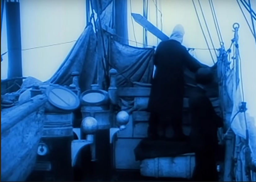
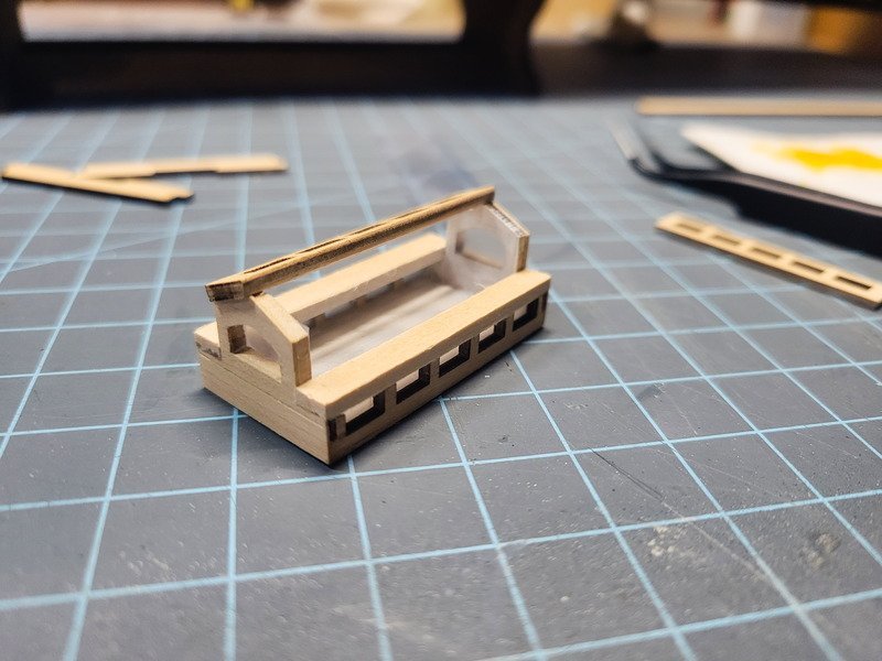
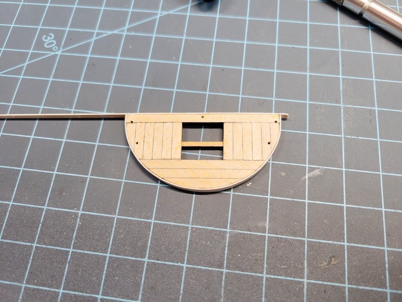
Thanks for all the likes and comments. Today was spent working on upgrading the mizzen deck skylight. It took a while to get it where it is, and it could definitely be better but I just built it along the way and ended up with the result. Perhaps if planning was involved, the ply ends would be hidden with the 0.6 thin stuff leftover from decking (which I didn't use anyway.) Here's what the plans call for:
There's a youtube video floating around that shows it at 4:51 in footage of the wreckage. Here's the reference I grabbed:

Indeed it's quite a bit different from what OcCre would have me build. I was thoroughly inspired by Clearway's skylight, so I began figuring it out by cutting the two window pieces in half, so as to use the smaller half as the bottom row of windows.
The base needed reworked to accept the new bottom windows.
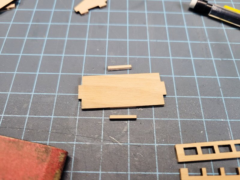
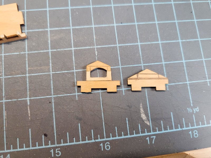
After mucking around with ways to build the ends, I decided to just cut the triangle piece off, then the ends of that to give me the top shape. A piece of 2x5 planking fit in the middle nicely. A jeweler's saw was used to cut the window from each piece. The original is on the right.
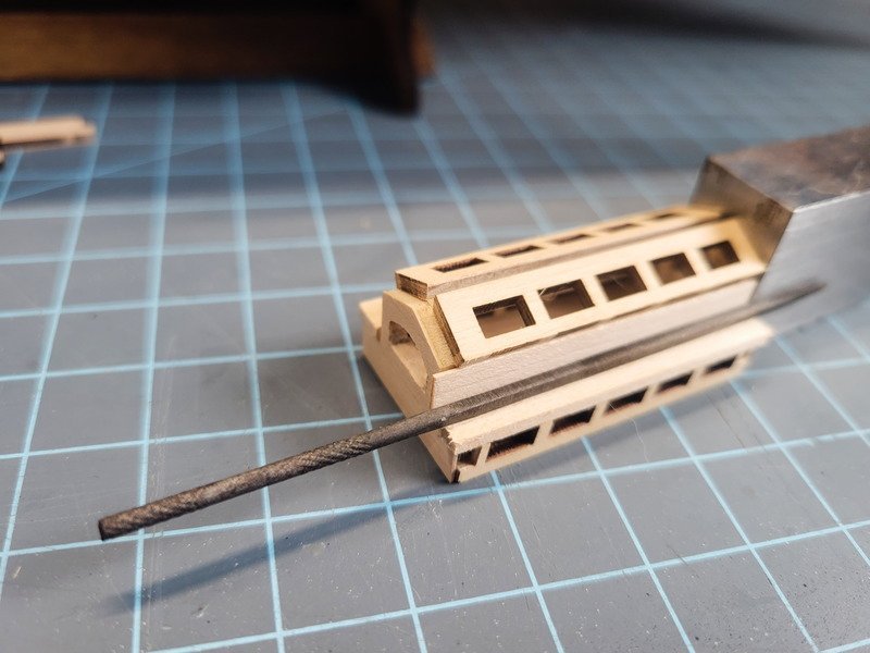
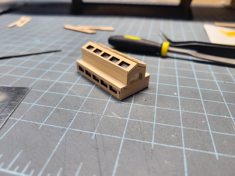
2x5mm was also used for the seat. 0.6 veneer made the vertical seat back. In this next pic, Somehow the whole assembly became 2mm longer than the top windows. I had to cut 2mm off of everything to accommodate.
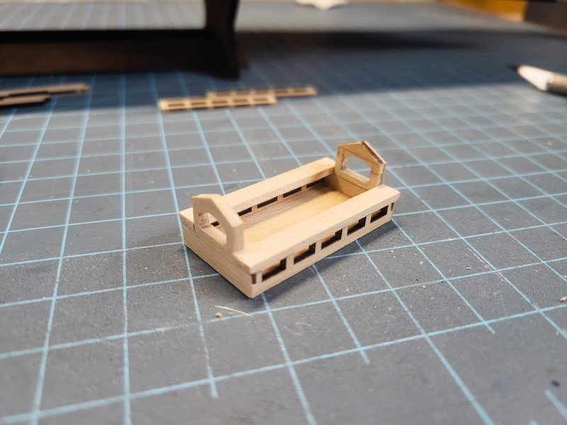
After gluing up to the seats I sanded everything and painted the inside white. I also installed the plastic window stuff, after roughing it up with 600g paper. The bottom windows ended up being 4 x 39mm, pretty small to cut and fit under the seats.
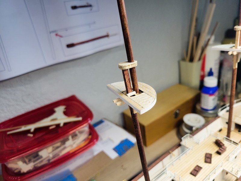
The whole thing was stained, carefully, with red mahogany like everything else. It's extra dark and not very red in the next pics because it needs to dry for a day or two. It should have the same finish as the kennels in a couple days.
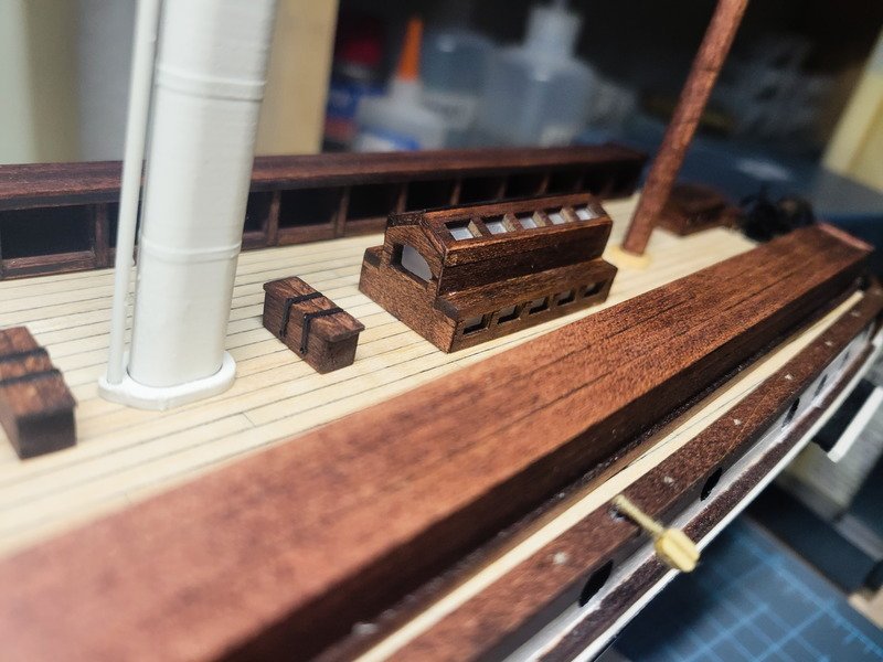
It's better to tell in the next pic, but I used 0.7mm brass rod (blackened) between the top two windows as a faux hinge.
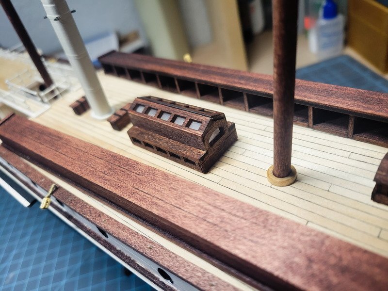
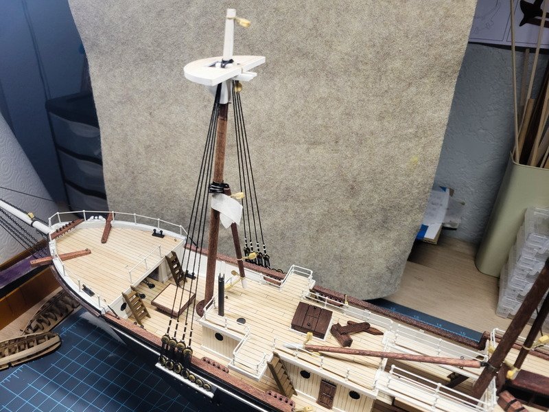
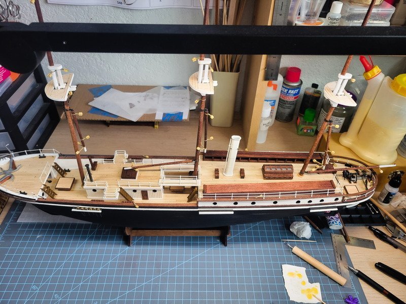
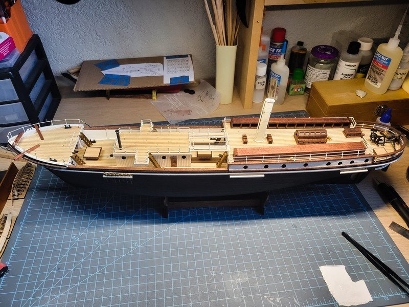
Overall view of progress so far. The masts and most of the deck structures aren't glued yet. I can also separate the top mast from the lower mast if need be.
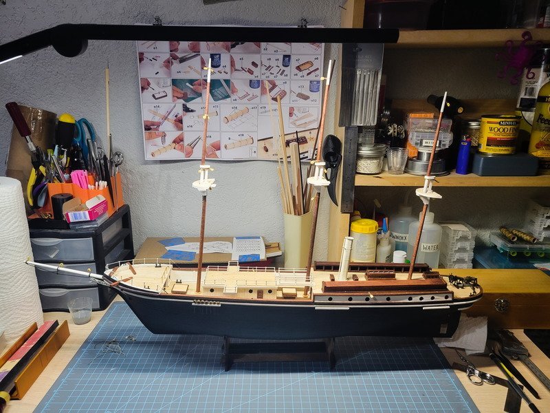
Thanks for reading!
- clearway, Hunt270, iMustBeCrazy and 2 others
-
5
-
On 9/24/2023 at 1:42 AM, clearway said:
Reference to the yard crane- also called a truss here you go:
Thank you! Is this from the book you recommended? Rigging the clipper and ocean liner?
On 9/24/2023 at 6:36 AM, Jorez de Saint Nazaire said:very nice you really upgrade the kit.
Sometime it would be interesting to use a figurine to evaluate the scale.1:70
Thanks François! I have a small strip of wood I have cut to 5' 10" in 1:70 (25.4mm) I've used to check scale. A figure would be helpful as well!
------------------------------------
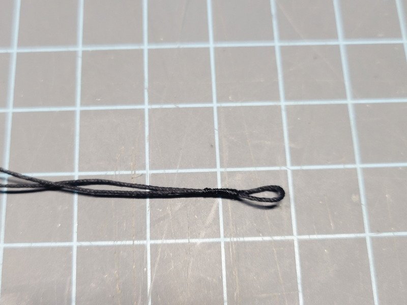
I received the Guterman Mara thread I ordered and made some 0.5mm rope, which I could then use to create the bowsprit foot rope. This is color 696, a very dark brown.
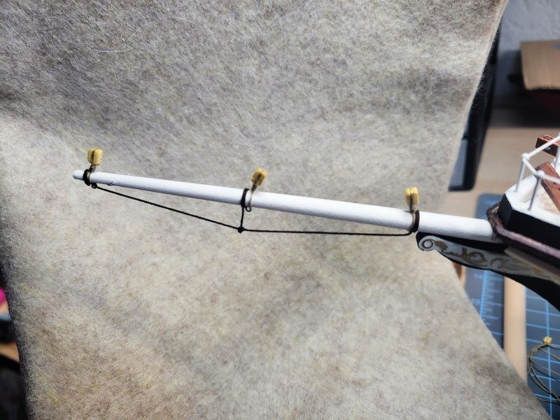
I tied the longer piece first using clove hitches and once I got it to the length it needs to be glued the knots with thin CA. Then an eyebolt (open one, not fully soldered closed) in the end of a clothespin was used to hang in the middle of the rope while I painted on diluted PVA. After 10 mins or so I could remove the clothespin and it held its shape. Then it was just a matter of tying the small piece on, gluing the knots, and cutting.
The remaining doors have been finished on the quarterdeck. I also installed "coal hatch covers" similar to how Tom did his with a paper hole punch circle painted grey with a nail stuck into the middle of it to simulate a handle.
And to finish up the doors I measured the aft companionway and built a single door to fit the opening.
I cut it in half using the jeweler's saw, drilled holes for the door knobs (nails that came with the kit) then stained and installed.
A couple of considerations: the doors will move the aft deck ladders outboard from the companionway a few mms. You can see because I've attempted the mizzen railings I have holes in the deck for the stanchions. The supplied brass ladders are now too wide for the aft deck, so I'll be scratch building them out of wood. Depending on how close I can get them to look like the other ladders on the ship I'll either use the brass ladders or make the remaining ladders from wood.
-
Thanks Keith. Do you happen to have any reference for a yard crane? I attempted to google it but didn't find anything definitive.
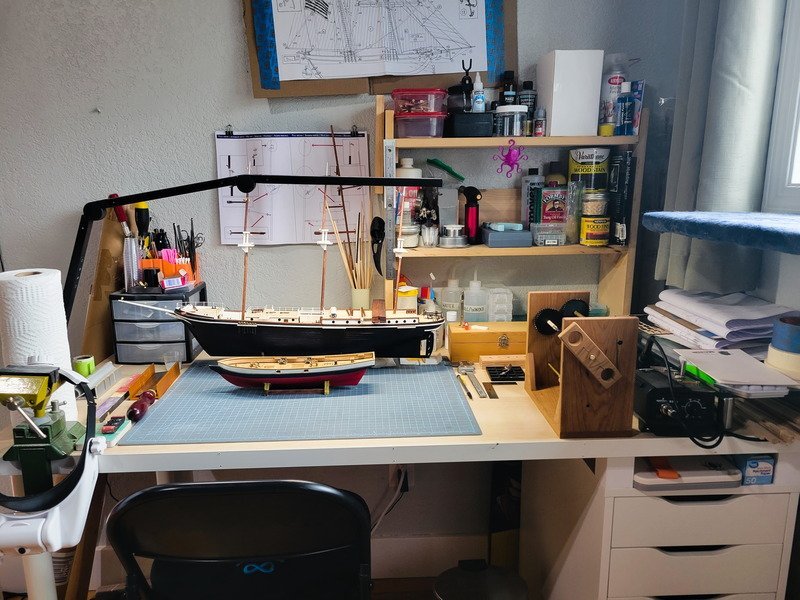
I ordered a bunch of stuff which came in all at one time yesterday so I had a need for a shelf before work continues.
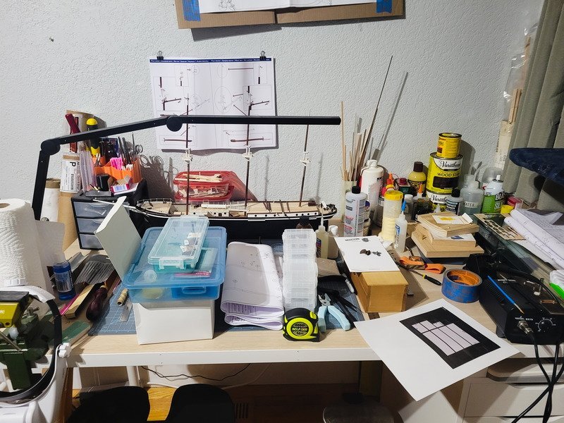

Much better!
-
Hi Sgmartz,
Tooling can be a pretty loaded question. What some can do by hand others will do by machine, so your skill will determine tooling requirements.
However, I can tell you what I personally rely on and feel as though are required tools for my skill set to build wooden models:
- #11 xacto knife. Blades can be bought online (generic brand, 100 blades in the box, few dollars)
- Cutting mat
- Good lighting. I paid $30 I think for an LED fixture that clamps to the tabletop. It has two strips, providing an angle other than "directly overhead". I'll attach a pic at the end so you can see what it looks like.
- Needle files. Amazing for shaping small wooden parts, and I've had mine for 10 years now and most likely will not need to buy more.
- Mitre saw box with saw. Make sure the slots in the box aren't too big for the saw. I had a wide-slot box for some reason and discovered they make thin-slot boxes as well. Total game changer.
- Micro hand plane. Planking a wooden ship is a feat that requires practice, and I've done two hulls without the hand plane. I'll never build another boat without that tool for the planking stage. I also purchased a plank clamping device for my current project, Endurance, and will tell you I tried it once and then bought the hand plane. Along with the plane you'd need a way to sharpen the blade from time to time.
- Magnification. I found a $13 headset that has several magnification lenses from Harbor Freight. I use 1.5x most times (and my eyes are fine) but not having the strain is helpful during marathon sessions.
- Various sandpaper. I typically use 80, 150, 220, 400, and 600. You can buy or create sticks and glue the paper to various sizes to have an assortment available to you.
- Clamps. All of them. You can never have too many. Clothespins, mini clamps, medium clamps, big clamps, alligator clamps, all of them.
- Tweezers. Micro and big types. It's helpful to have self-closing ones as well so you don't strain your hand.
- Dental picks for rigging. You'll find rigging to be a new experience and having the picks are helpful to move thread around your model.
- Needle threaders are a must in my opinion for getting thread through things. Alternatively you can glue the end of the thread/rope with CA and create a needle, but it doesn't last more than a few blocks.
- Glue. CA (super glue, medium and thin), yellow wood glue, and white PVA glue are all used. I have a bottle of diluted PVA glue that I can brush on things as well, which is just Elmer's white glue mixed with water.
- Hair dryer. Heat and water is used to bend planks. You really don't need to buy the "plank bender" but some really like it. I find a hair dryer is enough to get things bent, sometimes soaking the part in water first.
- Jeweler's saw and bench pin. This is the manual version of a jigsaw. I don't need to cut using a jigsaw often, so a jeweler's saw and bench pin is enough. But it's still handy enough to include in my list.
Getting into luxury items, I've found I use the drill press a ton, and the lathe has made tapering masts and yards a dream. I'm also tired of hand sanding 90* angles because I completely suck at it, so I'm planning on purchasing a desktop disc sander at some point. A small handheld rotary tool is in my future as well, but not necessarily needed. I've found I enjoy working with brass and have included it on my Endurance, so a soldering iron, solder, liquid flux, and a brass sponge are used. I have an 1/8" thick, 2" x 6" piece of steel flat stock with magnets on it to use as a building platform for small brass parts that need soldered.
Because I already have a shop in my shed I made a seizing machine and a rope walk with stuff laying around. You don't need them to build a wooden model, but they are specific to wooden ships and I find them helpful. You can purchase these two 'machines' from various places as well.
I hope this helped!
- Toolmaker, Landlubber Mike, Canute and 3 others
-
6
-
11 hours ago, Jack-in-the-Blue said:
Bolsters? I think I read about that a few days ago.
That's it!
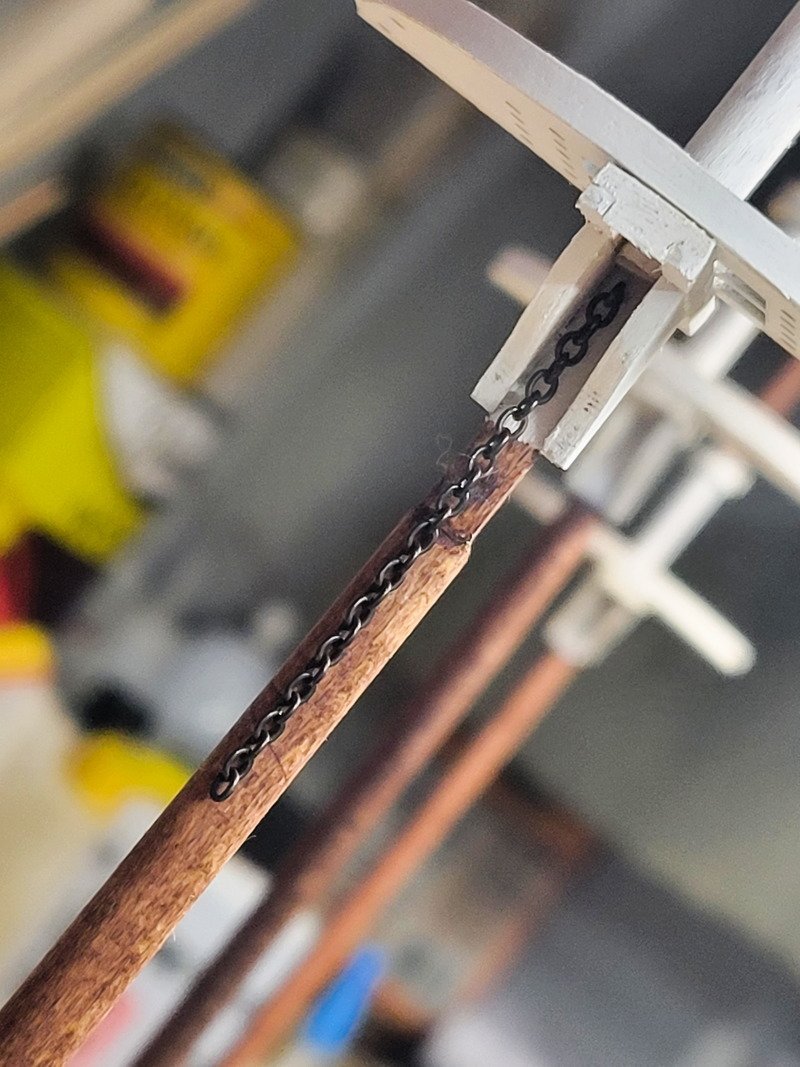
I've finished up the foremast. Since I squared off the planking of the mast top (the ply is curved), there's an eyebolt that gets installed at the bottom of the topmast that now won't fit. This holds the chain foresail sling, so I had to relocate it to the very top of the lower mast, just under the cap. Everything was already glued, so I drilled through from the back and was able to install an eyebolt with the chain already attached.
All blocks have beckets following the technique with a pin located here.
As for the mizzen railings, the entire assembly was too fragile to file the excess solder I left. There were parts of the balls that became flat, and most of the stanchions became un-soldered. The entire point of soldering it was to be able to paint it off-model without using a building board. I should've just cut a board, transferred the measurements, and built and painted it off-model like I did the deck house. Since that's the route that needs to happen, I went ahead and ordered new stanchions (I didn't have enough anyway, because I added more to the deckhouse than the plans called for.) I'll scrap the ones on the wire and eventually tear it apart and clean it up and use the pieces on other models. Not all is lost, I just have to wait a week or so to receive the new ones.
Once they're in I'll assemble them on the building board and paint without soldering. The paint will hold it together and will require touch up, but it'll be better than funky shaped stanchions.
-
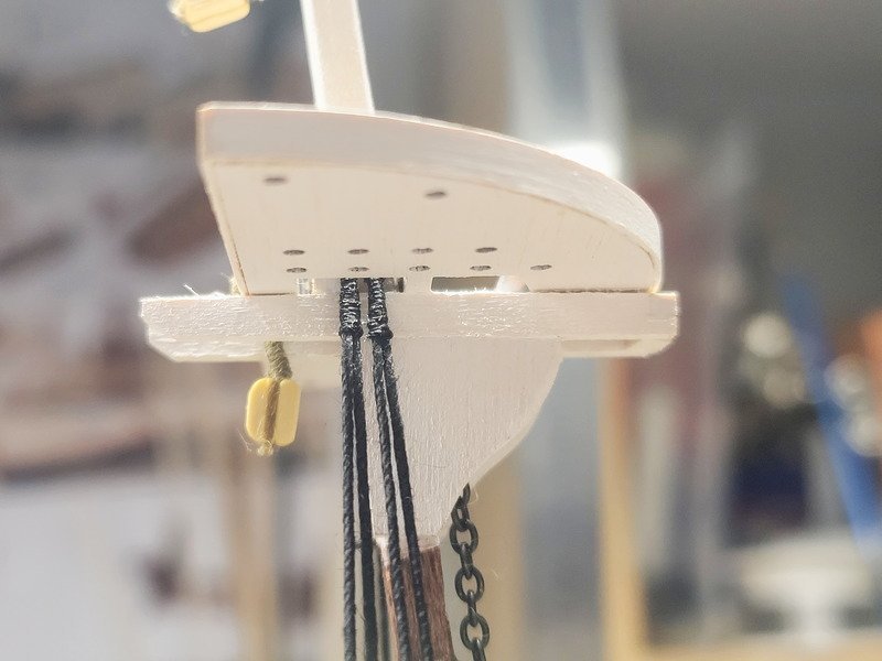
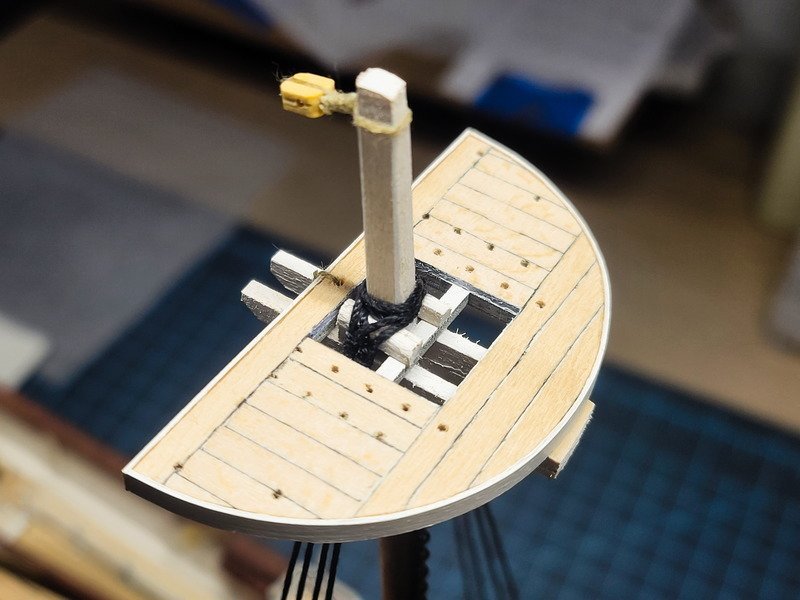
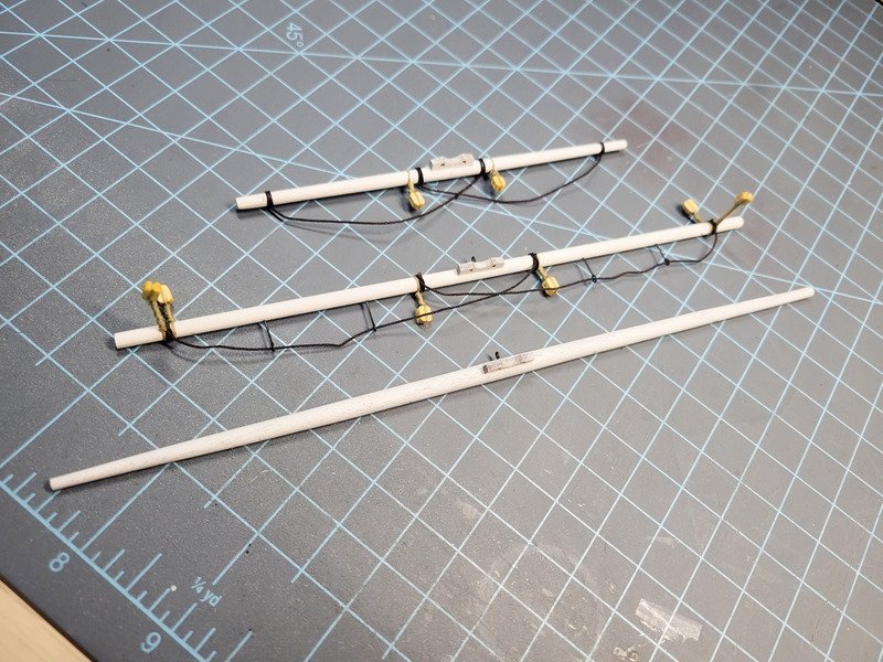
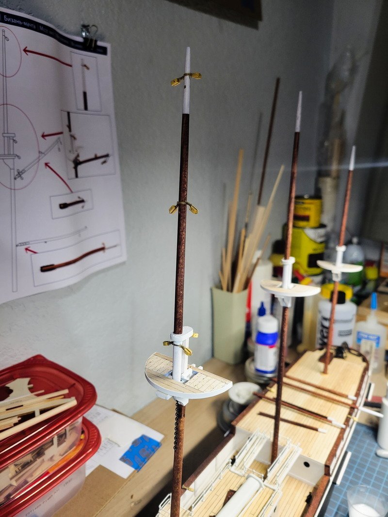
Hi folks, thank you for the likes and comments. Progress continues as all 3 masts have been built and stained, but they still need painted and blocks installed. That'll happen today, along with the mizzen deck railings. I started with the railings after my previous update but got seriously burnt out on soldering (punny!). So I switched gears and started tapering the masts.
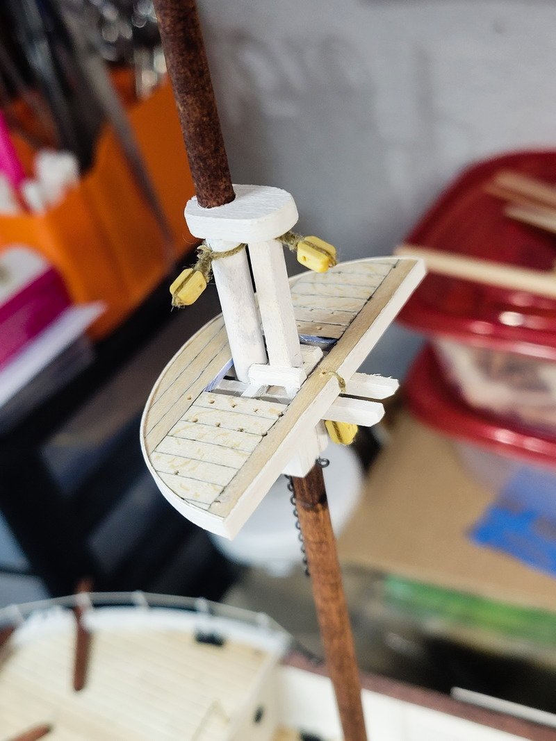
The plans call for a simplified mast construction with cheeks, 2 crosstrees, ply platform, and ply mast top. I added the small fore piece based on Frank Mastini's 'Ship Modeling Simplified' and also planked the top.
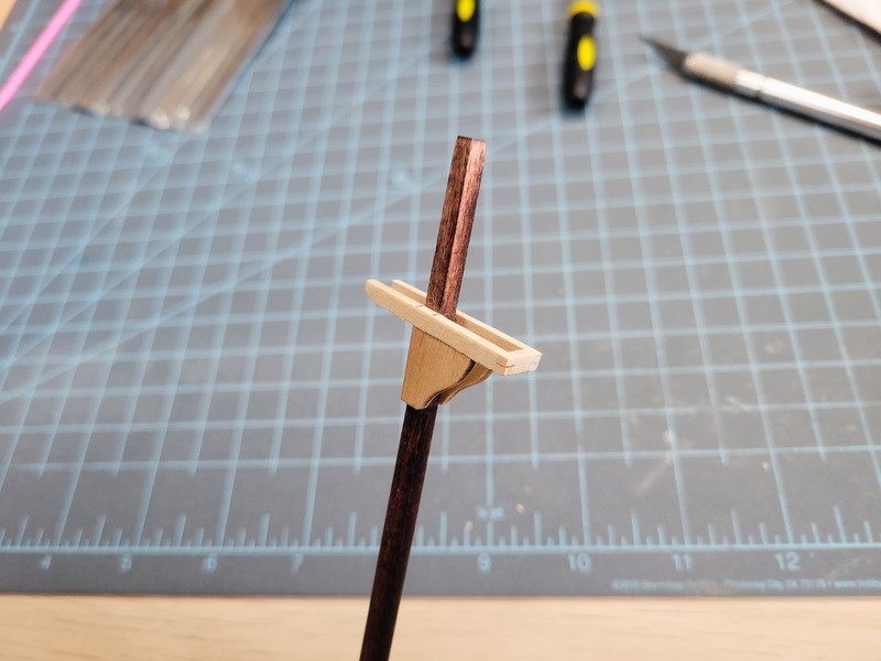
I also added (book isn't in front of me...I think they're bollards?) rounded-over 2x2mm next to the lower mast for the shrouds to lay against. Since I squared off the top of the lower mast, I also planked the top of the mast cap, so the square lower mast doesn't slip through the cap. The cap is glued to the top mast, and everything else is glued to the lower mast. In this way, I can separate the two assemblies and install seized blocks before it all gets glued together. Additionally the bottom of the top mast has been squared off so as to be inserted into the mast top. Everything is snug, so I can install into the deck and check alignment without gluing the masts together, or to the deck.
The plan is to do as much rigging as possible off-ship, and then install the entire thing when need be.
As for the mizzen railings, it's a really simple task which takes time since I'm building it on the model instead of on a building board like I did the quarter deck house (formally called ritz). I thought I'd be able to bend the stanchions to achieve the required angle as on the real ship, but the wood wasn't happy about that so I had to pull each one individually and bend them 1 by 1. The port side is soldered and needs cleaned, the starboard still needs soldered. Then I'll airbrush the railings, masts, and booms all at the same time.
Lastly I've decided not to push for realism for the rigging because I'm in a bit of an odd situation when it comes to building experience, as rigging is where the experience trails off. Endurance will be my 3rd hull completed, but I haven't rigged any of them. My first project, San Francisco, was 'lost at sea' unfortunately during a move (the log is in my profile if anyone wants to see it from 10 years ago). The Newport is on the bench as a 95% completed hull when I started the masts but didn't have a lathe at the time so the dowel broke. I had to order dowel from overseas which arrived a week or two ago, so progress can continue on the Newport at some point.
All of that to say, I am going to use Endurance as a learning curve to the rigging so I'm not focusing on installing every little line on the square sails. As mentioned @HakeZou has blazed that trail and I'm more than happy to follow his additions for this ship, which are plenty and add a lot to the rigging plan OcCre provides. So please forgive the historical inaccuracies (if any, I haven't researched it or traced the rigging yet).
I have a strong suspicion Terror and Erebus are in my future and I can see from the logs there are a ton of opportunities to bash/upscale, so for future projects I'll have more experience with the rigging and would be more comfortable adding things.


Endurance by theoracle09 - OcCre - 1:70
in - Kit build logs for subjects built from 1901 - Present Day
Posted
I'm not following you here Keith. I'm not aware of pinrails on those mast shrouds, do you have a pic or something to explain it better?