
Toolmaker
-
Posts
223 -
Joined
-
Last visited


-
 JpR62 reacted to a post in a topic:
Pretty cool tool: drilling positioner
JpR62 reacted to a post in a topic:
Pretty cool tool: drilling positioner
-
J11 reacted to a post in a topic:
Pretty cool tool: drilling positioner
-

Pretty cool tool: drilling positioner
Toolmaker replied to CPDDET's topic in Modeling tools and Workshop Equipment
Here is another tool offering the same capability but using a different method. This one uses a fixed drill shank size but the diameter of the material is less critical. https://hobbyisthaven.com/pages/dspiae-9-in-1-assistance-bench-tool?utm_source=fb&utm_medium=cpc&utm_campaign=Jun+18th+Dspiae+Platform+–+New+landing+–+UK%26CA%26AU&utm_content=Photo1_+Medium&utm_term=UK%26CA%26AU&placement=Facebook_Desktop_Feed&audience=new_cust&utm_id=120228898377920471_v2_s02&campaign_id=120228898377920471&ad_id=120228898378080471 -
 paul ron reacted to a post in a topic:
Where can I get small grommets?
paul ron reacted to a post in a topic:
Where can I get small grommets?
-
Toolmaker reacted to a post in a topic:
HMS Winchelsea 1764 by woodartist - 1:48
-
Toolmaker reacted to a post in a topic:
Le Rochefort by No Idea - 1/24th Scale - First POF Build
-
The link is to a short one page thread of mine showing simple “fittings” ideas. Those little spring clamps are used extensively. I find them continually useful with my ship building. Hopefully of some use Paul
-
Have a look here James. I think they do various sizes and it’s local. https://www.hannants.co.uk/product/CMK001
-
Fractal vise on kickstarter
Toolmaker replied to DavidG's topic in Modeling tools and Workshop Equipment
1.2 inches for the standard version and 3.2 inches for the extended version -
Fractal vise on kickstarter
Toolmaker replied to DavidG's topic in Modeling tools and Workshop Equipment
https://www.kickstarter.com/projects/metmo/metmo-fractal-vise https://www.kickstarter.com/projects/metmo/metmo-fractal-vise -
Toolmaker reacted to a post in a topic:
Napoleonic Era Miniatures by Thukydides - 1/700 & 1/1200 - 3D-Printed Hulls
-
Very enjoyable watching you develop your work on these miniatures. To remove the frustration of the fragile jointing on the masts I would default to soldering the joints. That would make them much more resilient to handling. keep up the good work Paul
- 36 replies
-
- 3
-
-
-
- Black Seas
- wargaming
- (and 1 more)
-
Toolmaker reacted to a post in a topic:
Le Rochefort by No Idea - 1/24th Scale - First POF Build
-
Toolmaker reacted to a post in a topic:
Question re "Line Off"
-
Question re "Line Off"
Toolmaker replied to JohnWW's topic in Building, Framing, Planking and plating a ships hull and deck
Thats as inspirational as it gets when it comes to planking. -
Need thread about 0.1mm in diameter
Toolmaker replied to Doug McKenzie's topic in Masting, rigging and sails
Fly-tying line should cover what you require. I have been using it with diameters down to 0.05mm. I am in the UK so my sources are not relevant, but you will find plenty of US suppliers. -
Kit review 1:25 Drakkar ‘Oseberg’ V3 - Ships of Pavel Nikitin
Toolmaker replied to James H's topic in REVIEWS: Model kits
The advancements in wooden kit development are just fantastic. 1900 +, pre cut parts, over 6 kilo’s of wood, months of entertainment and all for around £200 sterling plus import. It’s a great review and the fact that Chris is prepared to stock it, further adds weighty kudos.- 14 replies
-
- 3
-
-
- Pavel Nikitin
- viking
- (and 2 more)
-
Toolmaker reacted to a post in a topic:
Le Rochefort by No Idea - 1/24th Scale - First POF Build
-
Good advice all around there. You would be asking the saw to do something it isn’t designed to do and if something went wrong you would be annoyed with yourself. It might also likely be dangerous to try. Hacksaw, milling machine, metal bandsaw are all good options.
-
methods for serving a thin rope
Toolmaker replied to georgeband's topic in Masting, rigging and sails
Hi George, I have recently done what you are asking about. I served various size ropes from 1.1mm down to 0.45mm. I served the 0.45mm using 0.05mm diameter fly tying thread. This thread is 1/9 the diameter of the served line and I thought that was acceptable. With a little practice It was reasonably easy using the Syren serving machine. For me the issue was seeing clearly what I was doing. For the fine threads I used a magnifier to watch the thread. This picture shows some practice, but the serving thread was a bit too fine, however it shows the idea. I am a beginner compared to many so open to criticism if I am doing wrong. I hope something here is useful. Thanks Paul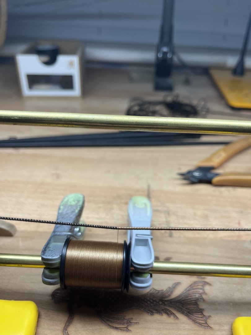

-
Beginner - Rigging Tools
Toolmaker replied to nheather's topic in Modeling tools and Workshop Equipment
Only this week have I finished rigging my HMS Cheerful so I am still running warm. I see lots of good advice above, especially about not buying tools before you have a specific need. You will certainly need 1 and likely 2 pairs of longish narrow tweezers and something to cut the line. I did most of my work with good quality small sewing scissors. My choice of make was fiskars. I also used a scalpel when rigging blocks off model. I used a helping hands system extensively and would find life more difficult without it. Used for stropping blocks etc. For serving I used the Syren version with some modifications, but I didn’t bother with serving on my first two builds. I use the same modelling clamps for adding tension to hanging ropes as I use during the build. The only thing I haven’t seen listed above which I like to have on hand are collapsible eye needles. They make threading through blocks a real breeze. The link is a uk one but I am sure you will find them anywhere in the world. https://www.thecuriousgem.co.uk/needles/beadalon-collapsible-eye-needles-assorted-sizes.html?srsltid=AfmBOoouysXEk_rNhhoVnaP66KHRpxEinAGwkJmAlkwoT-bk1JPEYrgt Enjoy the hull build first, then you can concentrate on the needs of the rigging. Good luck Paul -
Congratulations on your superb effort. Thanks seems so inadequate in consideration of all the pictures and instructions you have posted here. I am about to finish Cheerful having followed your build log alongside the instructions, as it is your level of skill, and more importantly, your patience, that is my aspiration. In the New Year I will begin my Winchelsea adventure and once again, I shall be using your build log as my guide alongside Chuck’s instructions. Cheers Paul
- 840 replies
-
- 3
-
-
- winchelsea
- Syren Ship Model Company
- (and 1 more)
-
Companies such as Dormer do drill sets down to 0.3mm which is a little smaller than number 80. These sets are readily available from various companies. Individual hss twist drills are easily sourced down to 0.2mm (-.008 inch). After that it’s getting specialised and prices start to take off. I’m in the uk so my links are only relevant to there. No doubt similar is available in the US.
-
Yes Todd, I agree. I can use them in my Sherline for the same reasons. Just not suitable for hand work.