


theoracle09
-
Posts
151 -
Joined
-
Last visited
Content Type
Profiles
Forums
Gallery
Events
Posts posted by theoracle09
-
-
3 hours ago, Jorez de Saint Nazaire said:
Hi,
At this stage it could be good to fit the garboard Plank but it is up to you.
Your log is very clear.
For the stern the ply former have the advantage to give the good geometry (volume).
Have a nice day
Yeah I think the ply formers are going to be the way to go. Balsa would be easier to sand, but the pre-cut ply would give the definitive shape. I'll be using the ply formers when the time comes I believe.
2 hours ago, Jorez de Saint Nazaire said:Hi
for the propeller ( I bought a brass one with 2 blades from Raboesch) ; type A diameter 30 mm M4 left (code 145-02).
Just for information.
FJZ

_resultat.jpg.d2e6d8541c541292af3fcc0ae1e09f40.jpg)
That prop looks really good! Did you leave it brass, or blacken it? The prop I bought is 2-bladed 30mm made out of bronze, and it's just barely a mm or 2 longer (fore to aft) to fit when the rudder support post is installed. If I were to buy a 25mm I won't need to adjust the false keel, but I may also design one and ask @Hunt270 to print it out.
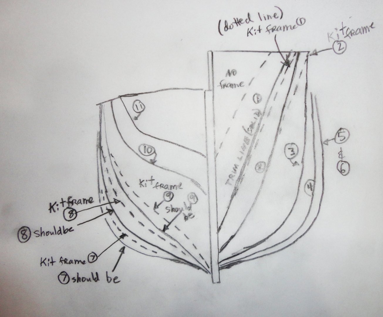
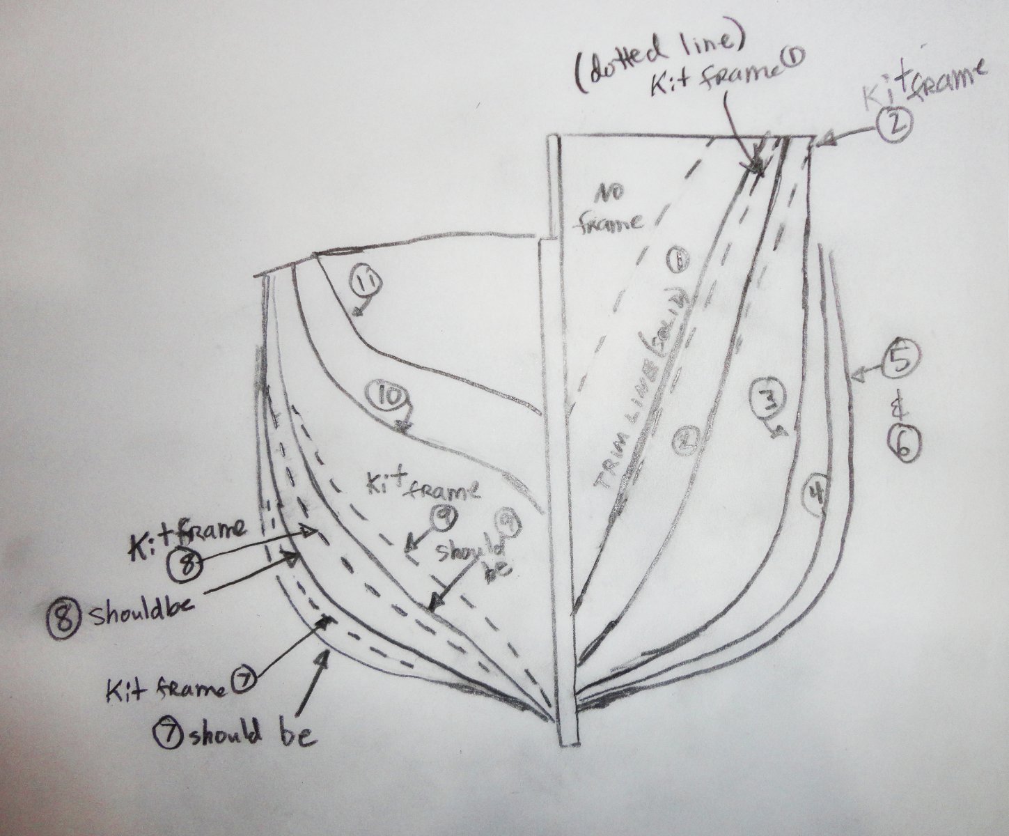
1 hour ago, Snug Harbor Johnny said:Seeing profiles of the planked hull that you have so far give a nice visualization of the lines - and something subtle I noticed in my kit review of OcCre's Endurance. The bow flare of the kit is a little more than seen in forward photos of the ship, as well as published lines. So I'll trim the first two kit bulkheads a tad to correct when the time comes, and this will impart a little less 'twist' to the solid bulwark piece provided (which can be pre-planked as you've already done. Bulwark installation and subsequent planking will then be a little easier at the bow.
Conversely, kit bulkheads 7, 8 and 9 are not as wide as the ship's lines would indicate, and one can see some lack of fullness in this area. New builders can revise these bulkheads (either by bonding additional material or cutting replacements on a jigsaw) prior to framing. Planking then would be less easy towards the stern, but would have correct lines. I suspect the designers opted for ease of planking, and the difference would not be noticed on the finished model.
The drawings posted in the kit review can be confusing, because there is no kit frame forward of the first one provided in the kit, so I made another to show the frame differences I'm talking about.
Thanks for the info Johnny! I'll admit that's one thing I didn't even think of to look at, so you have a great eye to notice the lines are a bit off.
43 minutes ago, Jorez de Saint Nazaire said:Hi,
More pictures for your demonstration. 😉
.thumb.jpg.d5f8ed56152f8cf06d9b8b169e424bb4.jpg)
.thumb.jpg.a52f2cfd82667d731560637751d555be.jpg)
.thumb.jpg.a186a1ecc82eb97a7e6185720b1ba7b0.jpg)
.thumb.jpg.e1fbd05e4406280c8bba1302469277b2.jpg)
.thumb.jpg.b04044adf55ca8015d7a34ea9612acc0.jpg)
.thumb.jpg.a09f42c23c4565a270b5033930dc9564.jpg)
.thumb.jpg.8e90634635049d2d024fee4b2e82dc5b.jpg)
.thumb.jpg.ec93037361a3236900013a0f7e385264.jpg)
Thank you for posting these pics! It shows me the runs of the different bands of the second planking, which I've decided to do. I like the first layer I have going on right now, but there are a lot of gaps at the stem on the port side. I've gotten a preliminary vision that I'd like to display the starboard side of this model. Not 100% decided yet but I'm leaning towards that arrangement.
-
Somebody's watching me ... 👀
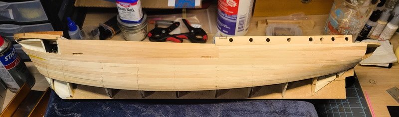
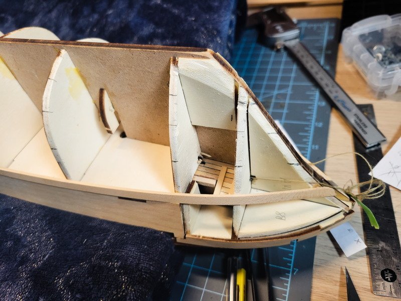
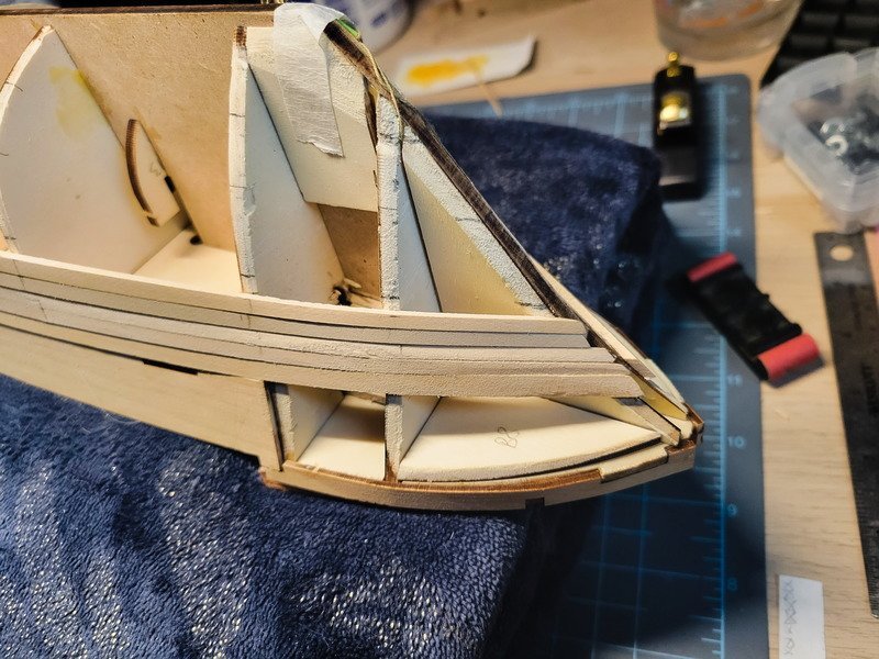
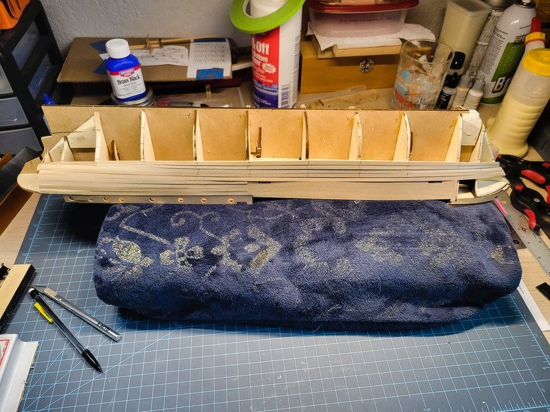
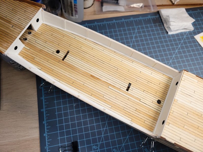
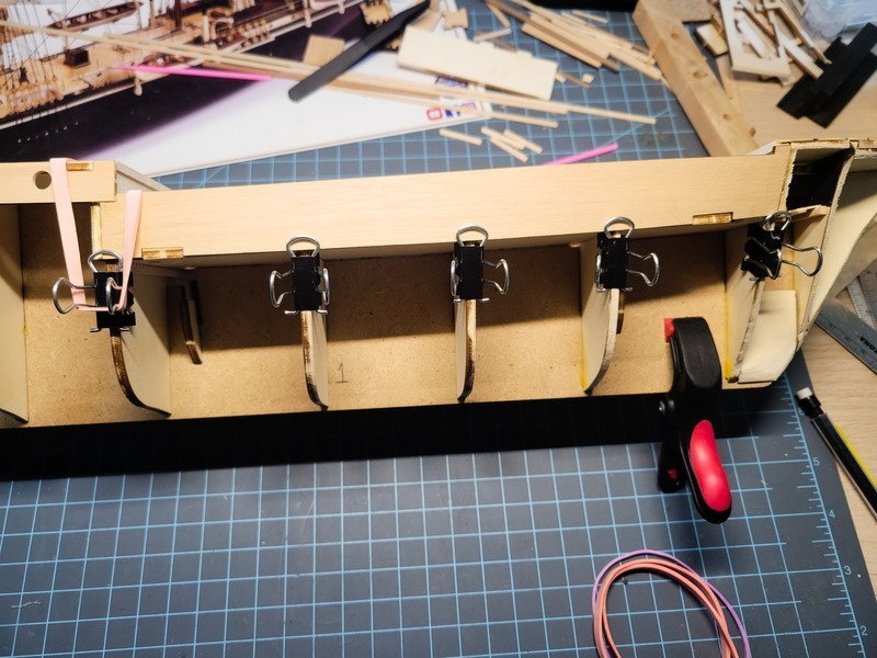
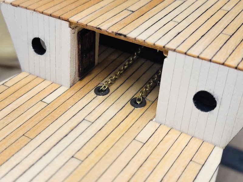
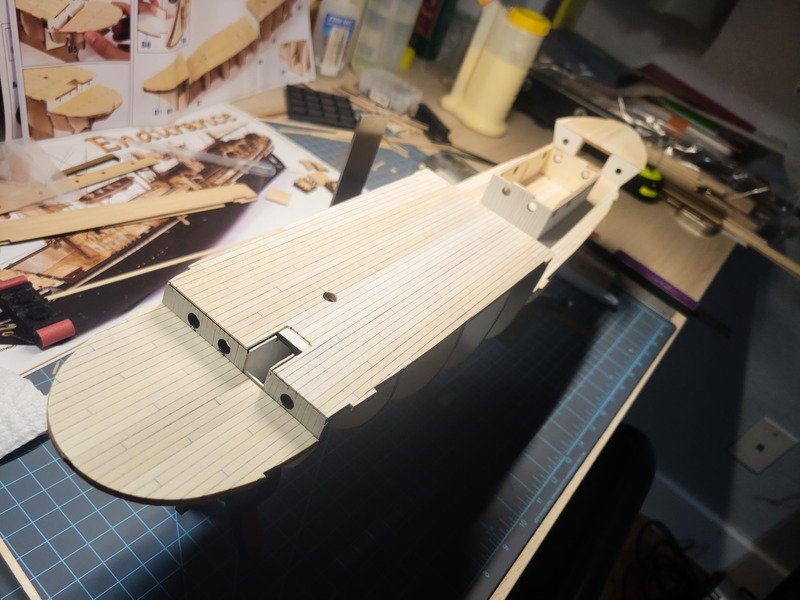
Hi folks, planking is just about halfway done, maybe 45% or so. Two bands on each side are complete, which leaves the final two bands and the upper bow to finish off. The next move is to clean up the keel slot at the bow and start looking at where the anchor holes are located. In the pics you can see some tape holding string and a small washer, this is tied off through the bulkhead to another washer under the anchor deck. I'll use it to fish the anchor chains to where they need to go when it's time, but the string needs to go through the hull before it's closed up.
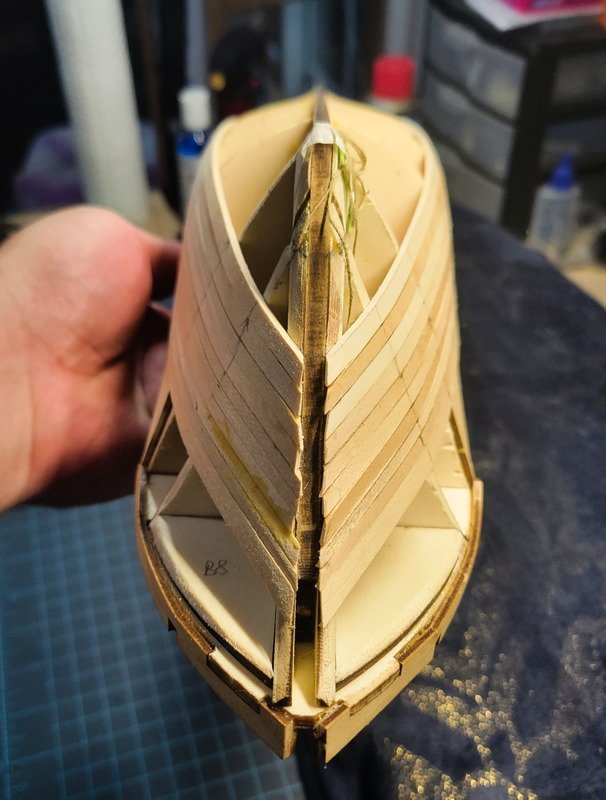
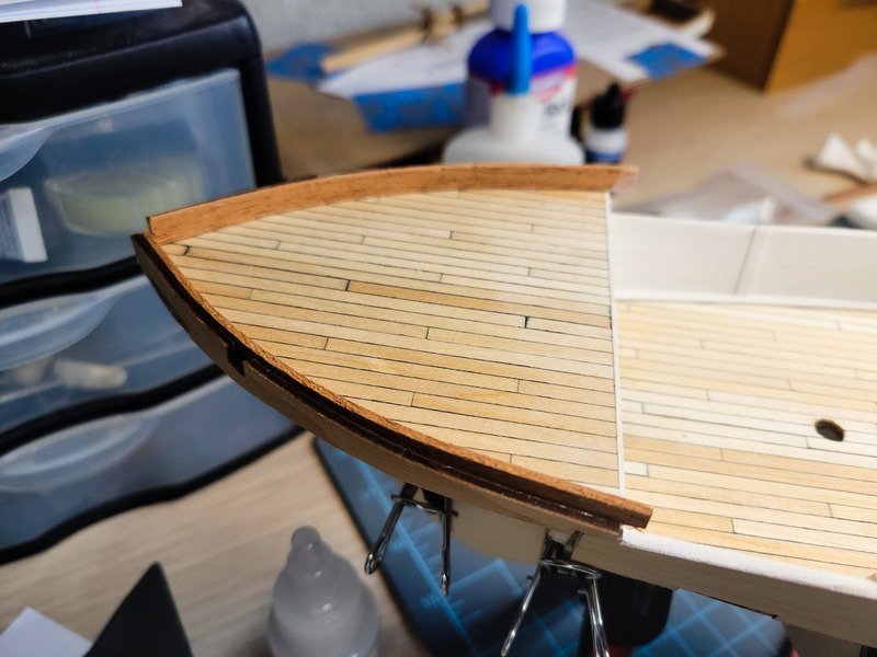
I didn't really start comparing each side at the bow until 3/4 up, and it shows. I had to purposely make two of them different sizes to get back on track. As I mentioned, this is supposed to be planked over with a second layer, so I'm using it as an opportunity to practice. I enjoy it, so why not. However, I'm extremely pleased with how this is going so far, I may not plank it again. My only concern is the stern. The kit has me building a bread and butter shim object out of ply, which gets planked over. Even with filler and paint, I know from my Newport build even when I think it's smooth, primer and paint will still show the timber below. Perhaps it's my impatience, so if I were to spend more time on filling and sanding the transition between hull and bread and butter ply, I could make it work.
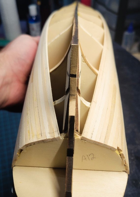
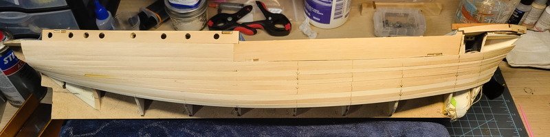
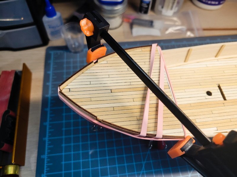
I was able to mirror the stealer on the other side nicely, although I didn't do the best of jobs trimming one of the planks it connects to (starboard side). I mixed up some saw dust and wood glue and spackled it in some spots just to cover the real heinous crimes. After a couple of hours the entire stern got sanded to 240 just so I have less sanding to do later. I stayed away from the bow and the last plank this time.
So, to second plank or not. Either way, the stern needs built up and I have balsa I can use instead of the ply formers which I might look at. I believe I've seen mentioned they go a very particular way so I'll be sure to pay attention to that. Once it's done and sanded I'll have a better idea if I can get it to smooth out under paint, or if it'll need the second planking.
Thanks for coming in!
-
-
27 minutes ago, Tomculb said:
Thanks Josh for letting me know I'm not as oblivious as I thought I was. 😁
Last night I finished planking the hull. I'll get some photos and a post on my log within the next few days. I'm hoping to leave it at one layer of planks, using a lot of sanding, filler and paint to hide all the blemishes. Regarding glue, I've always used carpenter's wood glue almost exclusively. I have often used a moderate amount of pressure (along with some water & heat induced bending) to hold pieces in place while the glue dries, and I've never had a plank spring loose. My oldest such hull is 30+ years. At least that's what has worked for me.
Awesome to hear it's finished! I look forward to seeing it in the next few days.
My plan was to use titebond for everything on this ship, but after seeing Chuck's videos and how fast the hull gets planked using CA I started using it. I'll switch back to titebond after planking is done. And actually, the CA is holding it all together at the moment, but once the hull starts closing up I'll go into the inside and spread around wood glue across the planks/bulkheads and in the corners to really hold everything.
-
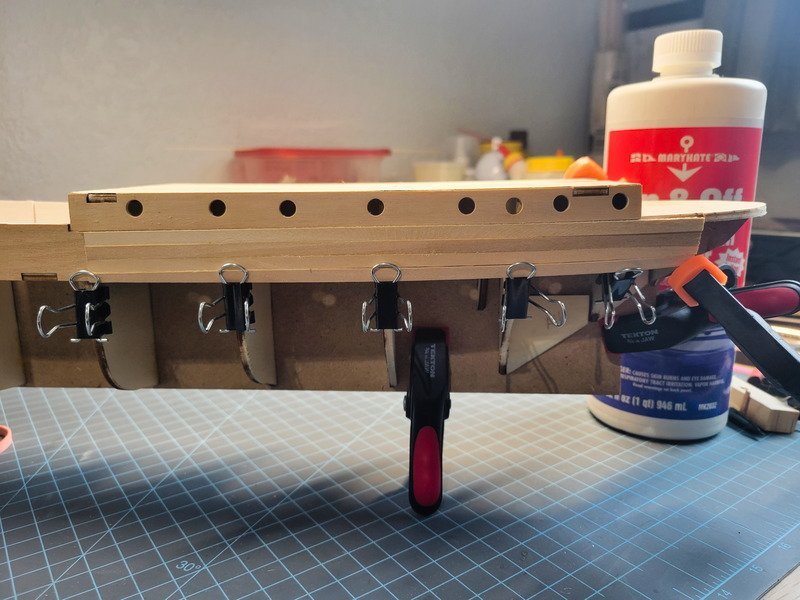
After a long and confusing battle with lining off the hull, planking is officially underway. I thought I'd be smart and didn't need to segment the hull (the very first step) which resulted in hours of lost time. My segmenting ideas didn't work, so instead of reinventing the wheel I followed the lining-off PDFs and things went much smoother.
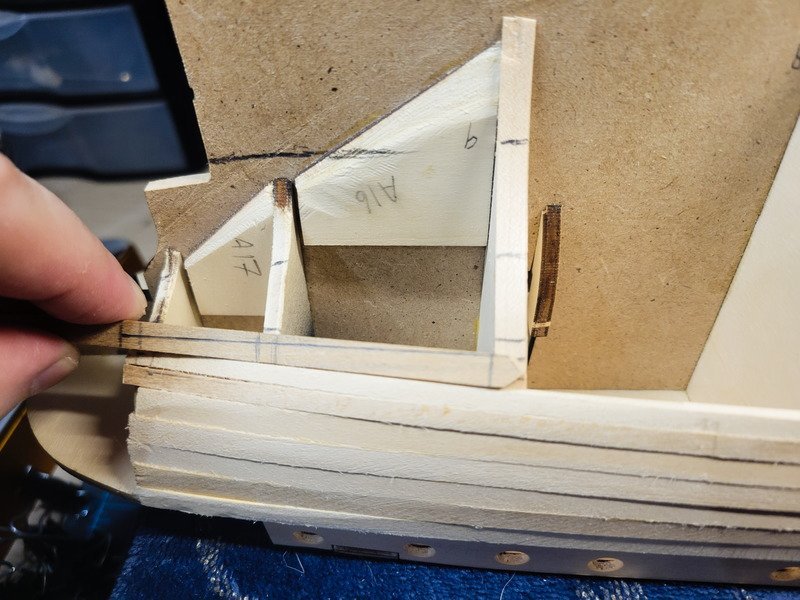
Speaking of smooth, the 3rd bulkhead in from the stern required shimming. I didn't notice this because I clearly didn't pay attention to it when I was fairing the hull. As mentioned previously I hate fairing the hull, it's the worst step for me mentally for some reason in the entire model building process. I used a batten to make sure it was faired, which it is, save for that bulkhead. I used 0.6x5mm planks meant for the decks to increase the bulkhead size.
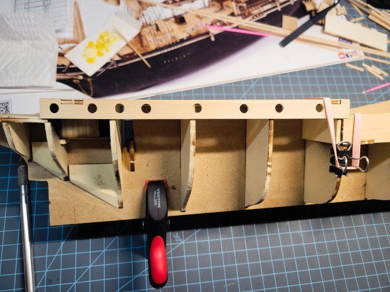
The frame required 3 strips on each side. If I didn't add the strips, one could sand the surrounding bulkheads to match, and we all know I hate that step so I opted to build it out.
I won't get in to the lining of the hull and all the dumb stuff I tried. It didn't work, so I did it exactly how it's supposed to be done and made 4 bands. I'm going to do a band at a time, on each side, so the hull builds up on both sides.
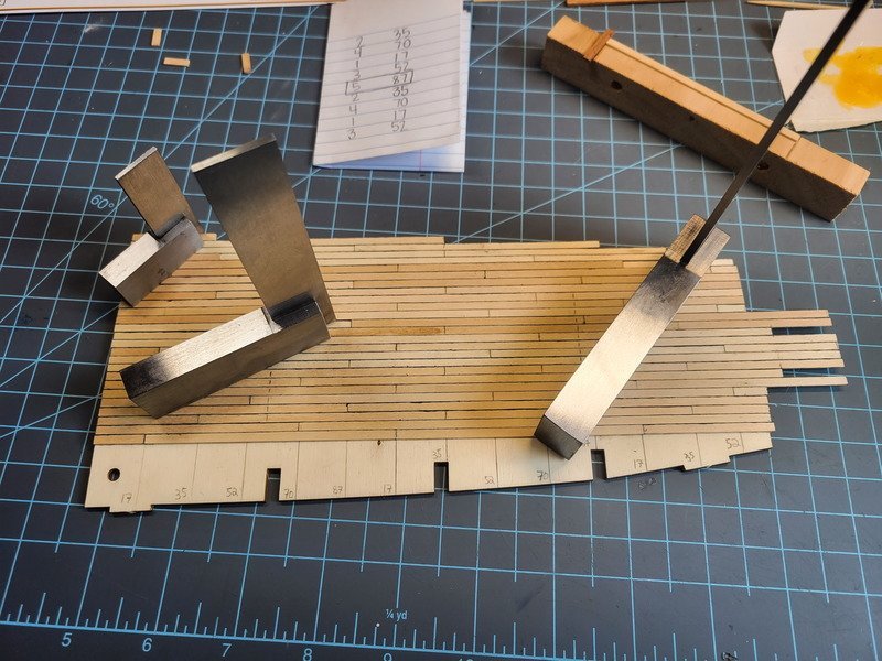
There are 4 planks on each side towards the stern I fitted and glued, and then a single plank running the entire length of the ship. This gave me a base to create the bands. In each band, I'll determine how many planks can fit at midship and base the current working band's measurements off of that as I go along.
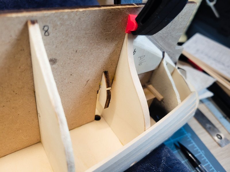
After installing planks on the port side I needed a stealer (or is it a drop plank? I'm not sure the difference) so here's a pic showing how that determination is made.
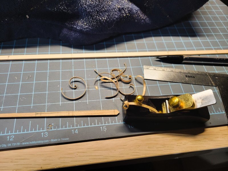
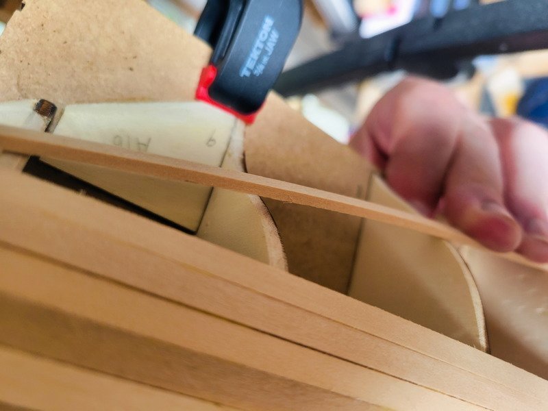
I'm used to using 1.8mm thick timber for hull planking, and the supplied planks are 2mm. That 0.2mm really makes a considerable difference when bending these planks. It seems more difficult and frustrating. I picked up a new micro-hand plane and holy moly, it makes the job of tapering a cake walk. This little thing is straight up hand-held magic!
Now I just need 1 more plank to finish out the first of 4 bands on the port side.
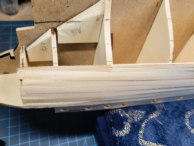
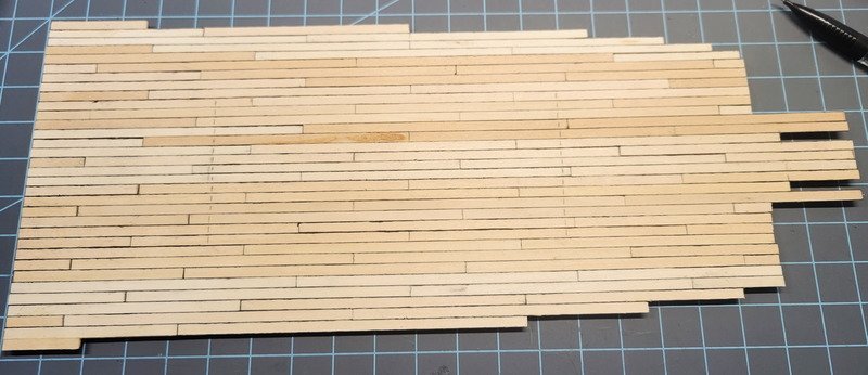
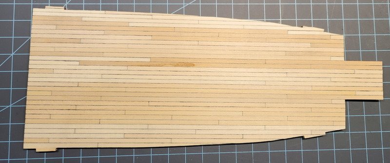
In the above pic, you can see my mistake. Before installed the top two planks, the third one from the top split just a bit on that first bulkhead after the stem. I tried to sand it out (which worked) but the angle needed to be better as I also took some of the top edge off of plank #3 from the bottom. That's where the chine effect is coming from, but with the planks so thick (2mm) it'll be easy to correct once sanded.
And here we are, 5 planks on the port side, 1 plank on the starboard side (plus the 4 on each side aft of the bulwarks. You can see the chine effect even more pronounced in that last pic. It's because I was beveling the wrong edge for all but the top 2 planks. But hey, lesson learned, and I'm excited to keep going because I think I've now "figured it out".
Thanks for reading!
- Vlax, HakeZou, MajorChaos and 1 other
-
 4
4
-
Just now, Tomculb said:
Josh, I don't know how the heck I overlooked your name, in your signature block of all places! And thanks for the info on where to find stanchions.
Tom
Oh no you're fine! I actually updated it after your post! You were right, it wasn't there before 🙂
Small update: The plans call for a simplified planking where you just slap planks down and when you need wedges, put them in. Since this is going to be double planked, it makes sense to expedite the process because it'll just be covered up. I don't really like doing it this way so even though it's going to be covered, I'm going to take the opportunity to practice planking the hull "the right way" by lining it out, doing some math, then spending time shaping each plank. Here is where my posts will slow down. I originally was going to use titebond for each plank and just wait for it to dry, probably overnight. I'm seeing where more and more folks are using CA now for the planks, only if the plank is prepared and pre-bent correctly.
I'll be following Chuck's method, outlined in videos located at this link. If the planks don't have any tension in them, CA should be fine to use and it'll last. However, if you rely on the glue to bend the planks and hold them down, the glue will deteriorate over time and you could find the planks spring away from their bulkheads years and years from now. If the planks don't have any tension in them, this shouldn't be a problem.
-
Thanks Tom, I appreciate you stopping by! Your words are very kind, thank you. I may not have a large post count, but I have actually been around long enough (off and on) to know about MSW 1.0, including having a portion of my San Fran log fall victim to it as well. The point is, I keep coming back to this site because of everyone's contributions and it motivates me to maintain a detailed log for others who build the Endurance as well.
The stanchions are 10mm 2-ball from Ages of Sail, you can find a link to their stanchion page here. They're based in California, so it took about a week from placing the order to receiving it. The kit stanchions are 12mm, and I decided 2mm won't be visible to the lay-viewer. As for the 1-ball, I purchased the 15mm size and am planning on cutting them down to 10mm to match the 2-ball stanchions.
1 hour ago, Tomculb said:We’re fortunately more than a dozen miles or so from what was the worst of the fires, but we’ve been buried in smoke. Raining today, which is good.
That's good to hear! We've been keeping an eye on it over the last week or so and was glad to see it being contained. We had smoke over the weekend but nothing as bad as on your side.
-
6 hours ago, Snug Harbor Johnny said:
Super job to date - especially pre-lining the bulwarks with thin planking ... another opportunity seized.
Thanks Johnny! All ideas I've garnered from others' logs, which I very much appreciate!
4 hours ago, Jorez de Saint Nazaire said:Hi,
The planking of the deck is vey nice and realistic, Bravo ! you really improve the model
Hi Jorez, thank you! Your Endurance model is beautiful, and is a source of motivation and inspiration!
2 hours ago, iMustBeCrazy said:Sounds good.
I've now come to pretty much the same conclusion although I think it was further forward (between the deckhouse and the beam). When they decked over the gap they would have fitted a hatch to access the hold with the crane, later they built a companionway on the hatch (or so I think).
And it's way past time that I said - Nice work!
Thanks Craig! Indeed I do agree with you. I always wondered what that hook was on the prototype model, hooked on to the railing. Until you said crane just then, it never occurred to me that's what the boom is. It's so funny, I've looked over pictures for hours pondering different aspects, and never knew there was an actual crane until now haha.
Work continues, steadily marching towards full time planking. The 3 planks below the officer's quarter portholes are now installed.
In between waiting for glue to dry I masked off the quarterdeck for painting.
I hand-painted the space between two stanchions and promptly said "nope" and masked the entire rest of the deck for airbrushing. It would have taken entirely too long as it would've needed more than several layers to hide brush strokes. The airbrush made short work of it and it's nice and even. I chamfered the edge of every plank on the bulwarks so after sanding and painting I'd still have lines.
Now the interior planking of the bow with the supplied 5x2mm was frustrating. I'm not sure what's going on with the timber, but it didn't matter what I did to it as soon as it started bending it snapped. I used heat, soaked and then used heat, soaked for even longer, didn't use heat, etc. So I grabbed some 1.8x5mm mahogany and made it work.
Finally I have a 4th plank now installed.
Thanks for reading!
-
Yeah I'm just going to call the structure on the quarterdeck a deckhouse at this point, as it does appear the Ritz was a different part of the ship.
I finished the officer's quarter's portholes. Both sides were drilled out to 1/4" using a forstner bit. I also faired the hull, a step I absolutely loathe for some reason. A bastard file took care of it rather quickly, but I still dislike doing the procedure for some reason.
Bulwarks also installed on both sides.
The ply that goes around the bow gave me no issues on the port side. I found when planking the Newport water isn't needed to bend the planks, just a hair dryer. I get it nice and hot (only takes 30 secs or so) and then put the piece where it needs to go and bend it slowly. I clamp it, dry, to cool down for 5 mins or so. Then I take it off and glue it. The port side went on just fine, however the starboard side is stubborn and broke when I glanced at it. It's currently being glued in multiple pieces.
The bulwarks have been lined from fore to aft horizontally (not called for in plans) and the stanchions installed. Once I get the inner bow bulwarks installed (it needs a 5x2mm installed against the ply, then cut to shape) I'll paint both bow bits and the lining on the quarterdeck/bulwarks white.
Thanks for looking!

- HakeZou, iMustBeCrazy, clearway and 1 other
-
4
-
1 hour ago, iMustBeCrazy said:
Well, that's thrown the cat amongst the worms!
By any chance, was the main hold used as the dining room during winter?
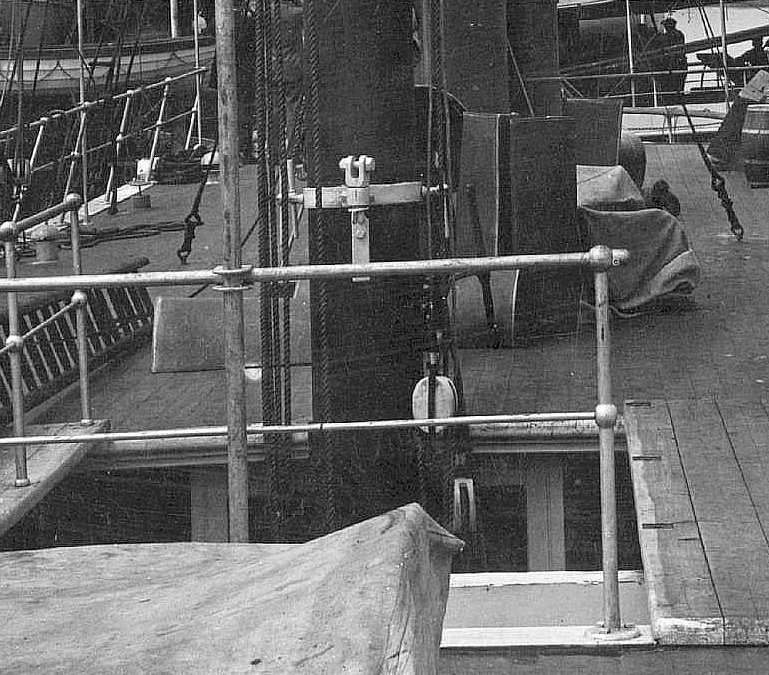
That might explain it.No, I don't think that works either. Then again, maybe.I assumed the pillars were to strengthen the bridge deck but I had/have a niggling suspicion the the beams aren't really 'ritz' quality. So perhaps they did duplicate the 'ritz' layout in the hold. I'm so confused.
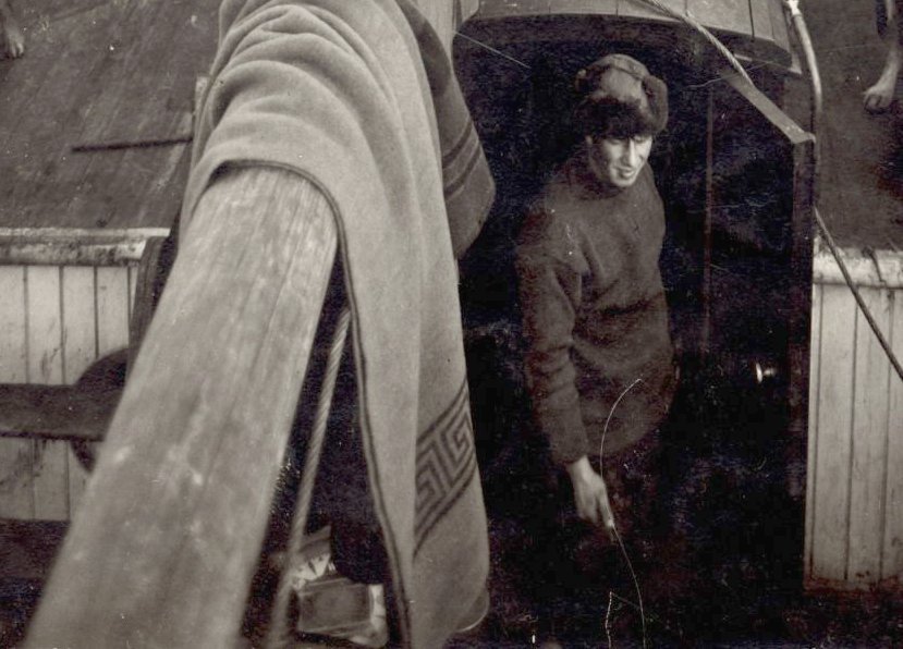
This shot shows a glimpse through to what I have been thinking is the galley but now I realise we should see a dirty great big stove if that was the case. Perhaps it's a servery below the galley?
It doesn't appear to be the Officers cabins as the 'servery' would be either the Captains cabin or one of the other cabins and the door would be wrong.
The door and the wall it's attached to are better quality than the partitions down the sides and are probably original. Could be the main hold/lower deck, bottom of the stairs.
Sorry, rambling. So many worms.
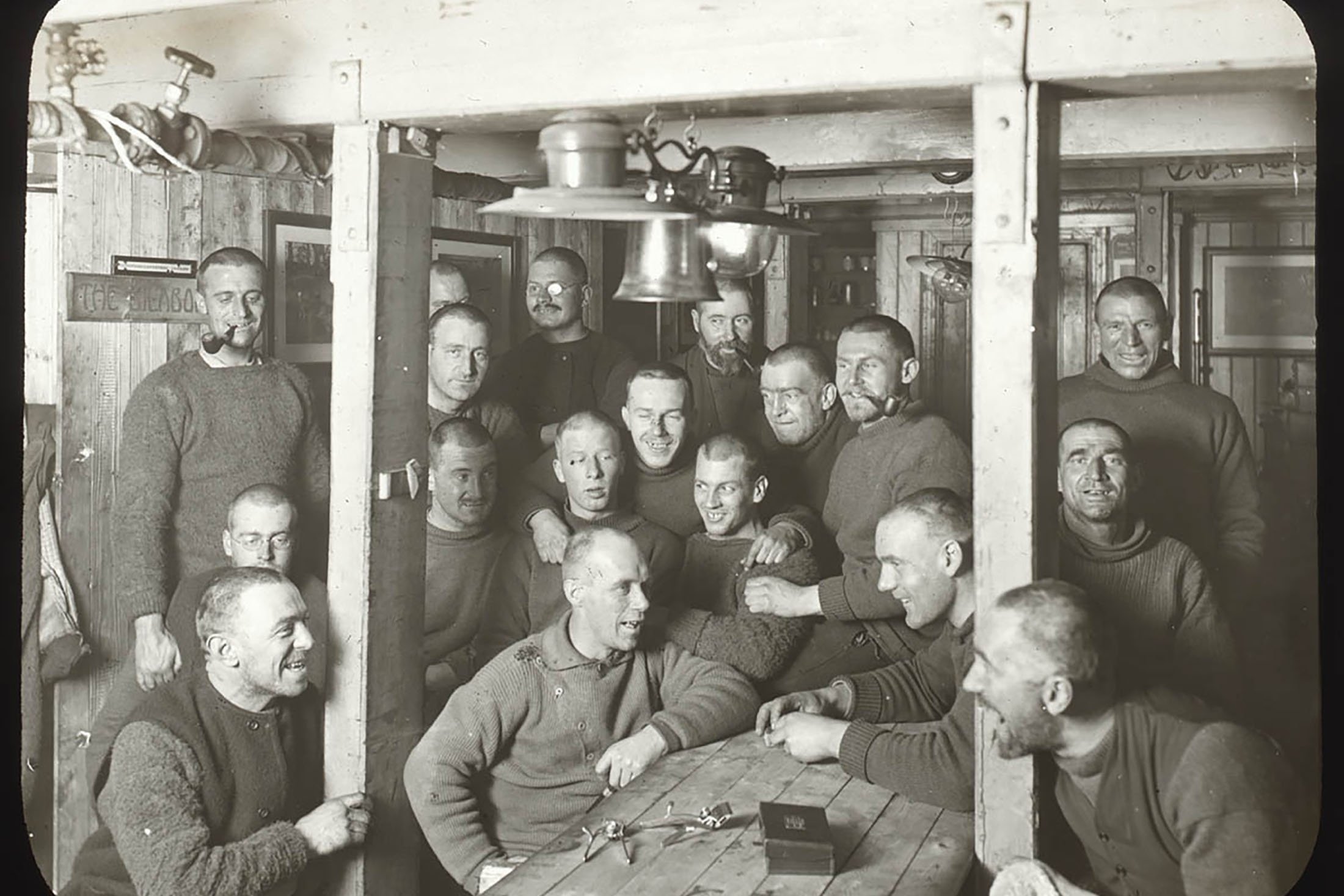
I'd say that pic accurately shows the ritz. Take a look at this passage from "South":
“The quarters in the ‘tween decks were completed by the 10th, and the men took possession of the cubicles that had been built. The largest cubicle contained Macklin, McIlroy, Hurley, and Hussey and it was named ‘The Billabong.’ Clark and Wordie lived opposite in a room called ‘Auld Reekie.’ Next came the abode of ‘The Nuts’ or engineers, followed by ‘The Sailors; Rest,’ inhabited by Cheetham and McNeish, ‘The Anchorage’ and ‘The Fumarole’ were on the other side. The new quarters became known as ‘The Ritz,’ and meals were served there instead of in the wardroom. Breakfast was at 9 a.m., lunch at 1 p.m., tea at 4 p.m., and dinner at 6 p.m. Wild, Marston, Crean, and Worsley established themselves in cubicles in the wardroom, and by the middle of the month all hands had settled down to the winter routine.
“I lived alone aft.”
-
On 8/26/2023 at 9:49 AM, theoracle09 said:
Building the railings on a separate board is definitely the way to go! I'm sure I picked up the hint from a log on here, and I apologize I don't remember who said it. But either way it worked very well, and is how I'll do the remaining rails when it comes time (if it's feasible to do so.) It took longer to drill the holes (making sure they were precisely aligned with the marks) than it did actually transferring it over.
The rails maintained their shape and the paint acted as a glue, as long as I was careful. Tweezers and magnification helped be gentle, and having the drilled holes 0.86mm (stanchions are 0.85mm) helped to hold them in place. I could then slide each one up and apply the tiniest drop of wood glue, then push them down and clean up the squeeze out with a micro applicator.
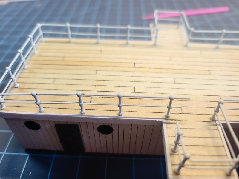
I've viewed some brass soldering tutorials and have a better idea of how to tackle the railings in the future. I'm also going to re-try the ladders with what I've learned. The point is, touch up was needed because the railings shifted ~0.6mm in some spots. Even just soldering (or gluing) the corners would probably have helped, but honestly, touch up paint took 10 mins or less so it wasn't a big deal.
And here we are. I'm extremely proud of how straight everything is. I was a bit worried about bending it and keeping the stanchions straight up and down, but it really wasn't that bad.
Well, dang. Here's another example of poor planning. I was so focused on getting the stanchions correct I forgot about the gangways. Now I need to ponder what to do about it. I could leave it, and not have gangways at all. But I really like the detail, so I'd have to think a while on that. Otherwise I imagine the entire run will need to be removed, because there are bends in the two aft corners. The 3 stanchions between the corners are in the wrong position (with the middle one being useless entirely). This means holes in the deck which would need to be filled, then new spacing established and holes drilled.
Or I could just leave it. Does anyone have an opinion on what to do?
Edit: Looks like I got lucky here. The distance between the corner stanchion and the next one is the exact width of the gangways anyway. All I need to do is cut the wire out, but all the stanchions can stay where they are.
-
Building the railings on a separate board is definitely the way to go! I'm sure I picked up the hint from a log on here, and I apologize I don't remember who said it. But either way it worked very well, and is how I'll do the remaining rails when it comes time (if it's feasible to do so.) It took longer to drill the holes (making sure they were precisely aligned with the marks) than it did actually transferring it over.
The rails maintained their shape and the paint acted as a glue, as long as I was careful. Tweezers and magnification helped be gentle, and having the drilled holes 0.86mm (stanchions are 0.85mm) helped to hold them in place. I could then slide each one up and apply the tiniest drop of wood glue, then push them down and clean up the squeeze out with a micro applicator.
I've viewed some brass soldering tutorials and have a better idea of how to tackle the railings in the future. I'm also going to re-try the ladders with what I've learned. The point is, touch up was needed because the railings shifted ~0.6mm in some spots. Even just soldering (or gluing) the corners would probably have helped, but honestly, touch up paint took 10 mins or less so it wasn't a big deal.
And here we are. I'm extremely proud of how straight everything is. I was a bit worried about bending it and keeping the stanchions straight up and down, but it really wasn't that bad.
-
Thanks Keith! I got the idea to split the rods in the middle of the stanchion from your log, so thank you for detailing that and logging about it!
That's a neat detail about the stanchion angles. I didn't consider this when I ran the rods, so I don't believe I'll be able to easily include it without significantly changing the length of the runs, which changes the corner angles, thus making the task infinitely harder because it's already painted. I'm going to have the boats positioned outboard, so I don't think I'll try and angle those stanchions. Had I caught that detail prior to running the rods I probably would include it.
-
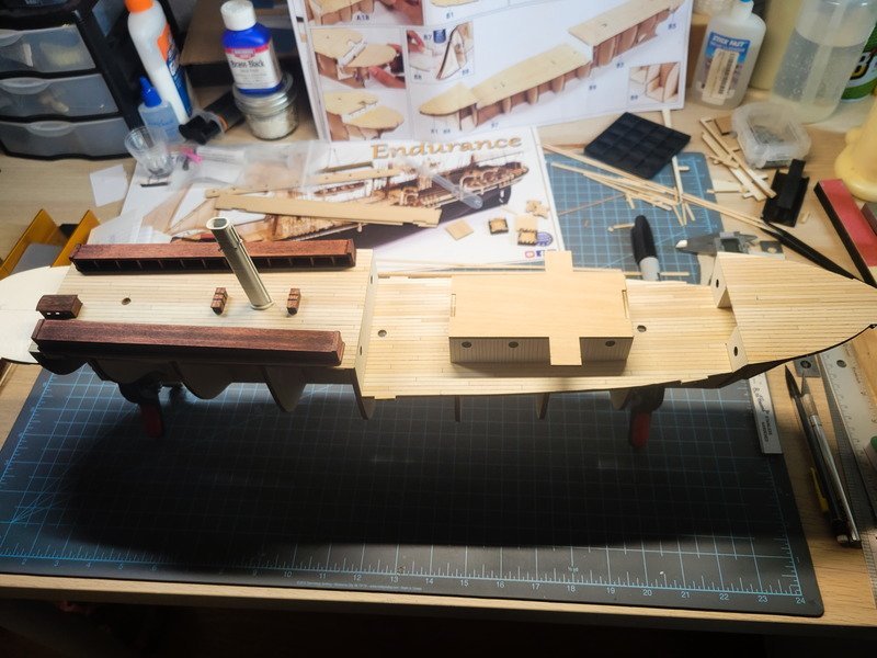
Hi folks, another productive day in the shipyard. I wrapped up instruction sheet "A" and "B" by finally gluing the false keel reinforcement ply in. I've also glued down the anchor deck, so all decks are now officially down. One thing I didn't mention in my last few posts that some of you may notice, I'm not going to be using the eyebolts on the deck around the masts. I'm sticking with a circular pin rail. I did grab a block and did a mock setup for running the rigging through a block attached to the eyebolts and I determined two things: 1. I just don't want to fiddle with it; and 2: I'd have to raise the pin rail high enough to clear the block(s) attached to the deck, which is unrealistically high on the masts for the sailors to utilize properly. I may replace the blocks, which would lower that clearance due to smaller blocks, but I haven't decided yet. I still don't believe I'll mess with it, so the rigging will terminate at circular pin rails.
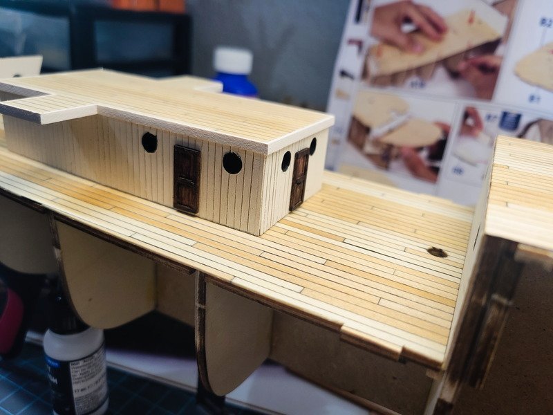
I began by trimming out the ritz with the supplied 3x1mm, then painting the off-white mixture. At the same time I trimmed the 3 deck transitions.
I ended up using the 3x1mm called for to trim the forward deck, so chiseling the space between closets didn't matter.
Next up I wanted to knock out the doors for the ritz. Originally I planned on making all 6 at one time to replace the brass doors supplied, but I got ridiculously bored after doing 4 of them so I'll save the remaining two for a later time.
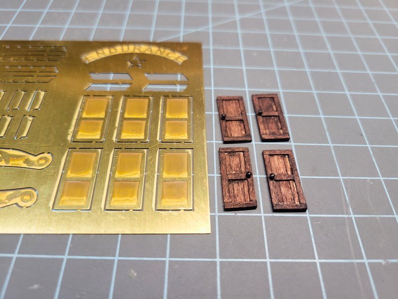
I know others have moved the doors on the ritz to more accurate positions, but I was in a mood after making the doors so I just glued them on where the kit said to. I've got no problem with them being in the wrong spots.
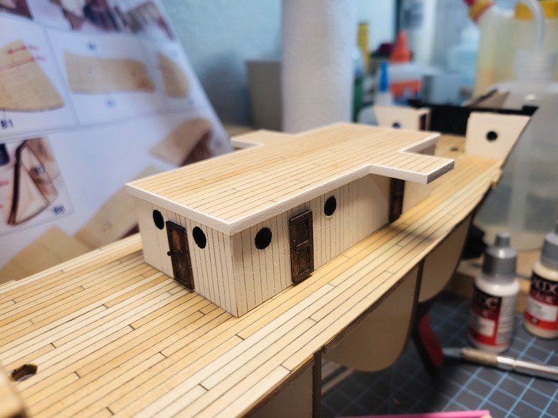
The port side door has the handle on the aft side, and the starboard doors have the handle on the foreward. I was thinking, if the ship was moving forward and someone opens the door, the hinge on the forward side would allow the door to swing normally. If the hinge were on the aft side, it'd really whip open, or be more difficult/require more force to operate. I have no idea if this is true or not by the way, it just "sounds right". A few hours after the glue dried I came to the realization that the wind is coming from the aft, so perhaps the hinges should be aft as well so as not to be whipped open by the wind. Hmm.
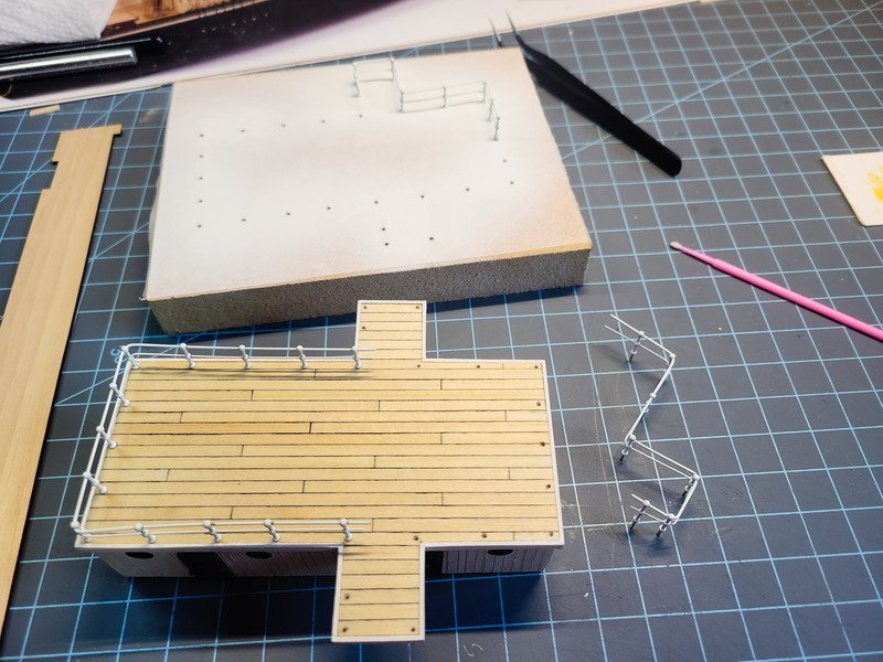
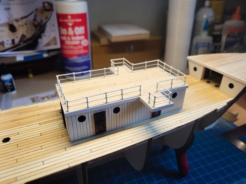
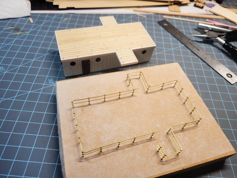
At this point I had clamps on the hull because I glued in the false keel reinforcement pieces. I decided to just keep right on going with the ritz and marked the stanchion locations. I transferred this to a 3/4" thick MDF board using tracing paper, glued on with spray adhesive.
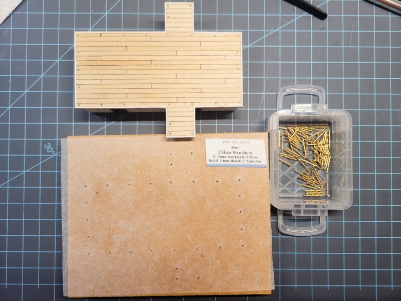
To note: these should be 12mm tall, but I couldn't find any in stock. I'm using 10mm instead. I considered somehow raising these up by 2mm, perhaps a small shim, but decided to keep my sanity instead and use them as they are. The holes were drilled with a press using the same diameter drill bit.
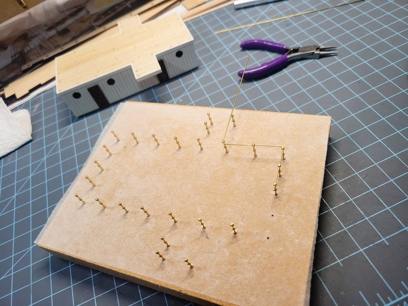
I'm using 0.7mm brass rod, not wire, for the top run. I don't know why I thought it'd be easier than it was, but it took considerable planning to make sure the corners are correct. This is my first time doing something like this, and I'm certainly satisfied with it, but knowing what I know now, the next one will be better. A big tip here is to grab the top ball of the corner stanchion with non-serrated needle nose pliers (with both runs inserted) and start twisting, keeping the stanchion straight up and down. Manipulate the rods at the same time. I was able to bend both runs most of the way, to get the corner stanchion facing 45* to both sides, then continue bending just the rods to the next stanchion location.
I will say doing the bending was significantly easier to do off model than on. If I were doing this on the ritz I guarantee something would've pulled the wrong way and scratched the deck, or ruined the stanchion holes, etc. I'm saying all of this before I have to move it, so we'll see if I feel the same way trying to get it from the board to the deck.
I tossed around ideas for what to use for the second run. Having it be the same 0.7mm rod was out of the question. Pics show it to be smaller than the top, so I grabbed some 0.3mm black rope I made. I considered how it would paint, and then it hit me: moving it would be almost impossible. Then I stopped over-thinking it and grabbed the abundance of 0.5mm rod I have for eyebolts. Because of the number of 90* corners, I had to remove almost all of the stanchions in the above pic from the top 0.7mm rod to insert the smaller run. Knowing that, it made the rest of the runs much easier because I inserted and bent both runs at the same time.
The whole assembly is split into 3 different pieces. In the pic above, the middle stanchion in the run at the bottom left, the rods are split so they equally fit into the stanchion. That way I have the port, starboard, and then separately the aft assembly to move to the ritz, and the middle stanchion hides the break.
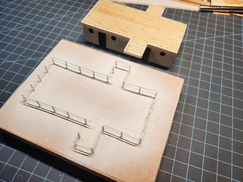
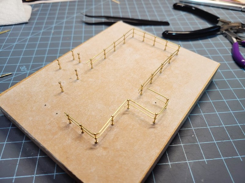
After several coats of paint, it's ready to move over. I'll drill the ritz sometime this weekend and see how bad it'll be to move over. I'm expecting a lot of touch ups, but I believe it'll transfer over just fine. I left the rods long on purpose to aid in keeping the stanchions on. I didn't use any glue at all, which might cause issues, but I justified it because the holes are so snug trying to remove a single stanchion would break a solder or CA joint. Probably. Maybe. I considered soldering it together, but recently attempted to solder the ladders together and had a terrible experience. The heat from one side would desolder the other. I really want to pick up a micro-torch soon. Something about using wet cloth or paper towel or something to keep the finished joints cool? I'll have to look into brass work more, and is something I want to improve on.
This is a long one, I appreciate you taking the time to check it out!
-
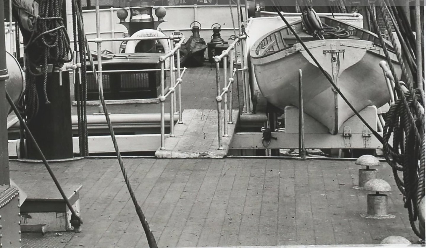
22 hours ago, iMustBeCrazy said:
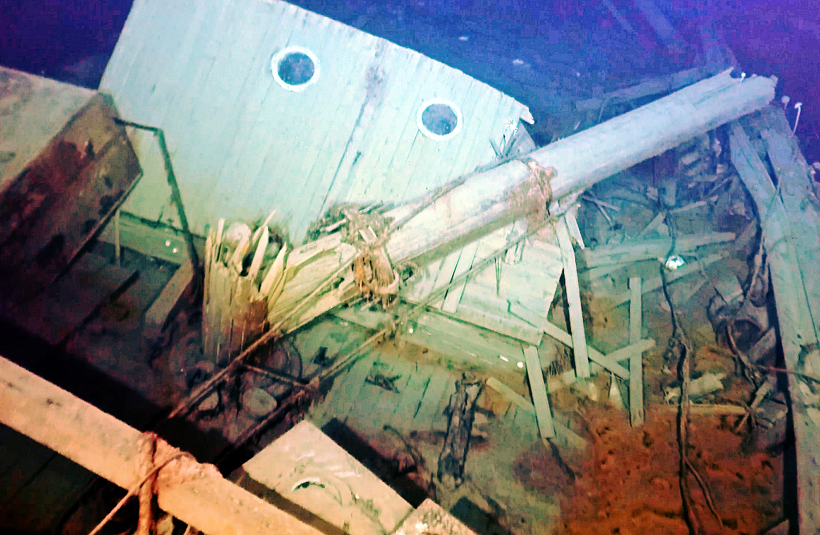
You're moving along. I was trying to get ahead and was looking at the bridge deck access.
From what I can see of the wing bridges they are surrounded by solid railing and it would seem the companionways have a landing at the top with a right angle turn to access the bridge deck proper.
Then I found this:
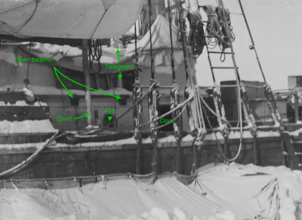
It would appear that the starboard wing bridge and companionway were removed, the raw ends of the beams suggest that it was probably after getting trapped.
Hmm, I hadn't noticed a wing missing before. That's a great observation. I'm going to keep both of them for this build, but it could be interesting to take it a step further and remove one/both of them if there were more pictures of that area when they were stuck in the ice.
12 hours ago, Hunt270 said:Just catching up on your progress! Looking fantastic.
Thanks Will!
Big picture update today. I used a penetrating oil on the deck to really bring out the grain and it really makes the sharpie caulking stick out as well, but it's not over-bearing.
After drying a few hours they received a coat of tung oil and were left alone to dry for another few hours. I then decided to glue them down, except for the anchor deck. It took 32 hours total to planks and finish the decks, so I was excited to get them glued in. This was a mistake for two reasons, one of which you'll see further in this post. The second reason being I talked about shimming the mast supports in the false keel and didn't do that. It would've been easier to accomplish this if I were able to pull the decks off to glue shims in, then replace them to check the mast fit. Now, I get to fumble-fart around under the decks with tweezers.
When the anchor deck is installed there's an angle of viewing where you can see there isn't a floor after the closets. See this pic:
So I added a few more planks.
This is much better. I also chiseled out the bottom thickness from the anchor deck between the two closets. I haven't decided if I'm using the 3x1 (which would hide it anyway) strips for the trim that the kit calls for, or if I'm changing it to something else. So if I do change it to something thinner, you won't see the plywood behind it.
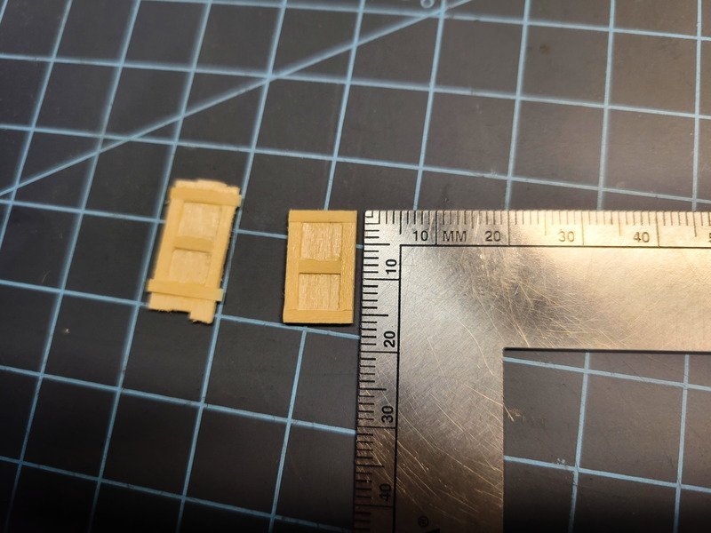
To get the anchor deck glued in I'll need to first create the doors to the closets. I laid down some of the decking material on blue masking tape and started assembling two doors. The finished dimensions are 16mm x 9.8mm.
In the below pic, the one on the right has been sanded down to remove thickness. I didn't measure it, but if I'd guess the doors are 1.5mm thick or so. I sanded the top, removed from the tape, and sanded the bottom as well. They are very thin doors.
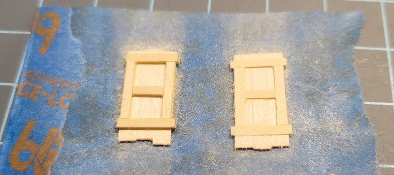
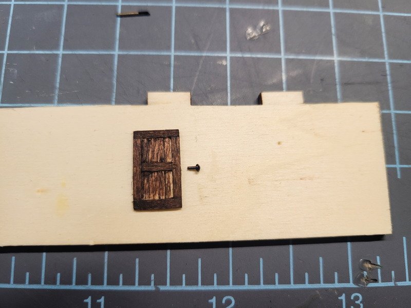
I need to do a better job cleaning up glue squeeze-out, as this is the reason the stain didn't take in the corners of the inside panels. All well, it's so tiny and hidden, it won't matter. I took a nail from the kit (I won't be using them for the planks anyway) and used a sharpie to blacken it. After the nail was glued in I brushed over matte varnish over both doors and handles to kill the shine. I really like the look of these doors, especially the knobs. There's a good chance I'll be replacing the brass doors with home-made doors similar to these (just a bit bigger I believe).
Next up I was cruising other logs when I realized I totally forgot Tomculb's awesome details he included with the anchor chains traveling through the hull, through the first bulkhead, and then down below the deck where the rope/cable store would be located. I wanted to include the same detail, but already glued in my bulkheads and decks. No matter! I'll take a hand drill and make short work of it.
Sigh. Gotta show the mistakes too, right?! Of COURSE the spot I chose to drill was half on/half off the bulkhead under the deck, so when the bit hit it it caused the bit to push forward and eat the deck planks. As you can also see, I drilled bow to stern into the first bulkhead and caused major chip out from the back. This is the result of a momentary lapse of fore planning and it'll happen again, I'm sure. The cool thing is, it's totally able to be hidden.
I took two brass porthole inserts (credit to Tomculb here on the look and method) and filed them flat a bit, then chemically blackened and glued them in. Here's the result.
Ah, much better! Phew. The damage lies directly in line with the chain, so technically no harm done. And you can't see that back wall with the deck in place due to the black paint so all looks to be well now.
Thanks for stopping by!
-
Thanks for the likes and looking in! I've completed the mizzen deck and a couple hours after that finished off the aft deck and began the bridge. I'm definitely looking forward to being done preparing planks and gluing decks. Something to note, none of the decks are glued in right now. I also grabbed some 6mm dowel and checked the mast fit after drilling out the deck planks. I noticed it's rather loose at the false keel (but nice and snug around the deck), and I really don't want to rig something up later to make sure the masts are raked correctly, and are straight between port and starboard. I'll be adding some shims at some point so all I need to do later is step the mast and it'll already be in the correct position and ready for glue.
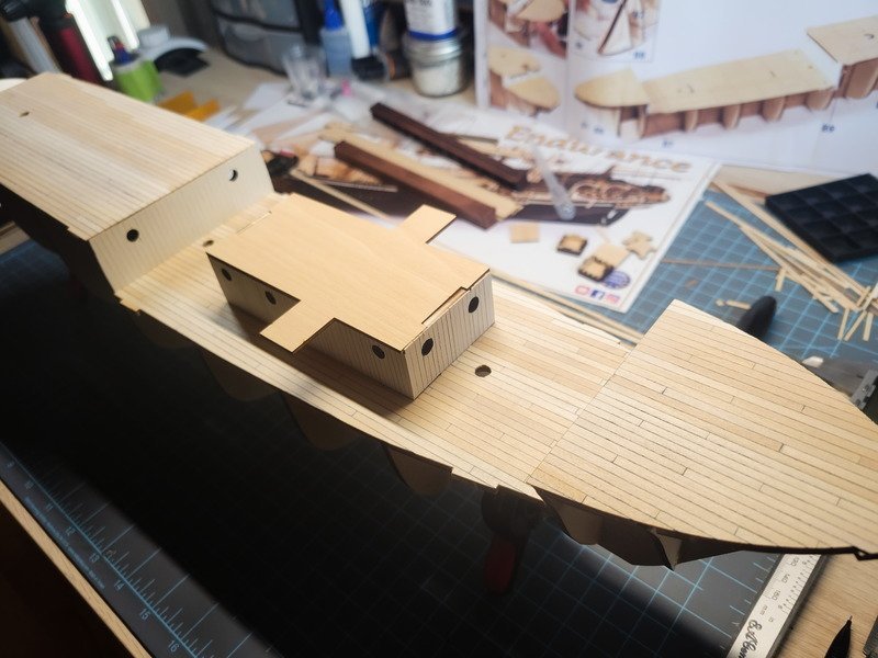
Pic before I planked the aft deck. Nothing is glued down right now.
Everything is nice and smooth and I'm really happy with how the decks look. The timber I purchased seemed to have been mixed in with some smaller stock and I didn't catch it until in the middle of the quarter deck. It's rather noticeable if I take a close-up on the anchor deck. I'm not worried, I plan on having a busy deck, so it'll be easily covered.
I also didn't catch the color variations in the timber. My wife pointed it out on the anchor deck, but I think I like the different color of the planks. It's a little distracting right now, but once there's "stuff" elsewhere to look at I think it'll add to the look I'm going for, which is a well-used ship with a lot of different detail everywhere.
One thing I thought of while keeping my mind busy planking, for anyone building this after me, if you want to cut the bulkhead under the anchor deck to include that space under there, grab whatever planks you're going to use and lay them out on the quarter deck towards the bow to get a sense of spacing. If you plan it out correctly, you can cut your bulkhead at the precise width of whatever number of planks that'll fit between them and still look good.
- iMustBeCrazy, clearway and HakeZou
-
3
-
7 hours ago, clearway said:
They also had cleats incorporated into blocks as well just to confuse matters even more! On the main mast apart from the tackle to use the boom and the halliards for the sail the braces for the foreyards would lead there- if you look carefully there are also pinrails on the shrouds just above the deadeyes. I have Harold Underhill's "rigging the clipper ship and deep sea carrier" as a source of reference but havn't delved too deeply into yet.
Keith
Ah yes, even more stuff to look in to! I won't be rigging for a while, but sometime between now and then I really need to start learning the different terminology and how it all works. I'm not too concerned with rigging it 100% correctly, but we'll see how close to that I do end up getting.
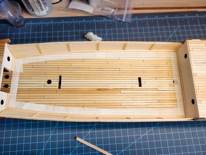
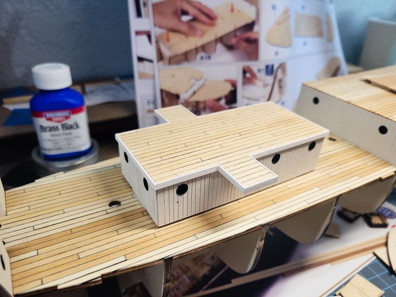
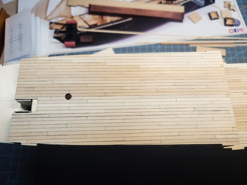
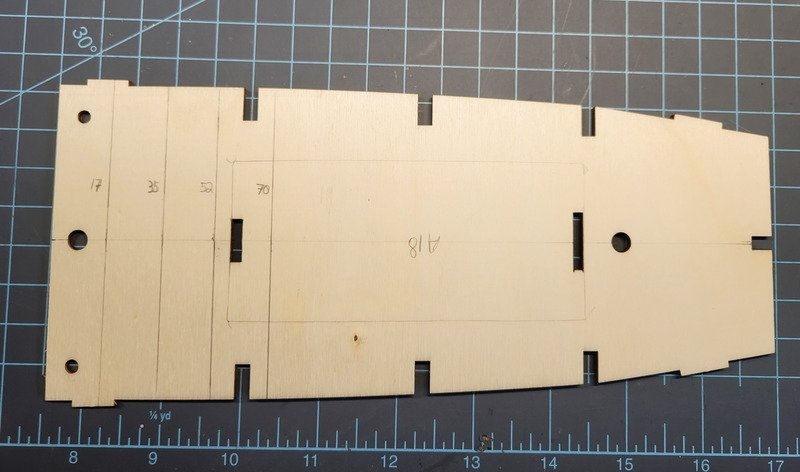
I finished off the quarter deck this evening. Cutting and prepping each plank becomes a chore after a while, so the observant among you will notice I opted to use continuous planks for the portion of the deck which is under the ritz. This won't be seen, so to save time I didn't worry about the pattern. I started by marking the deck with measurement lines and dry-fitting the first planks.
You'll notice the pattern in the following pictures because I marked the butts under the ritz with pencil so I didn't confuse myself.
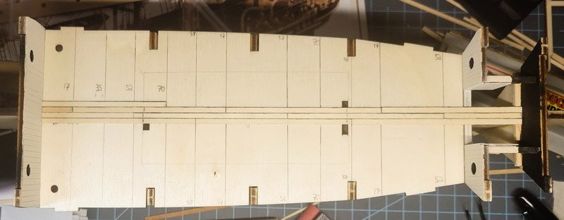
The plywood deck had a twist in it after cutting from the sheet. I used machinists squares to hold it down while the titebond dried. This worked the twist out and now the deck lays flat. The measurements on the paper refer to the length of the first plank from the left. After that first plank, every plank in the run after it is the #5 plank, or 87mm. That's how the pattern is established.
And finished. The final planks under the anchor deck would be installed after the majority of sanding was done.
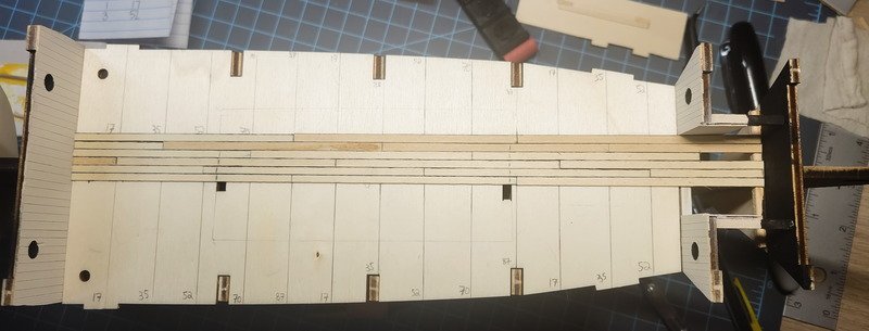
I started with 150g, then 240g, then 400g. You'll see here the pattern butt lines under the ritz are now gone. I also placed that ugly knot under the ritz on purpose.
There's the smallest gap in the forward space on the starboard side under the anchor deck. It should easily be covered though by some trim. It fits perfectly otherwise.
Pic with the ritz more-or-less where it'll be installed.
Thanks for reading!
- HakeZou, iMustBeCrazy, clearway and 1 other
-
4
-
Thanks Craig! I'm still a ways away from permanently deciding, so for now I'll stick with the pin rails and not worry about the spider band on the main.
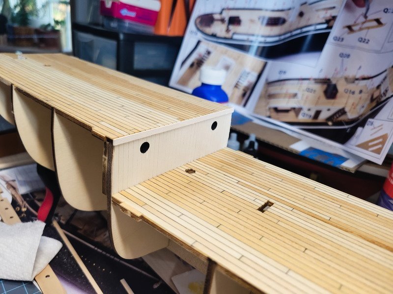
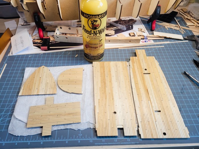
I received the timber for the deck today so I began on the anchor deck ... deck. I took a look through other build logs and I wasn't able to determine if there was a "right" way to deck the Endurance. The plan shows planks running the length of all decks with no butts, and I haven't been able to find any butts in any of her pictures.
So I decided to add butts anyway because I really like the detail it brings in. It's a way to separate the grain and a classic part of the "model ship" look. I looked around and landed on this forum post and decided to do the same pattern. The measurements for a 20' plank at 1:70 works out to 87mm. For the ratio 5:2:4:1:3 the deck planks should be 87:35:70:17:52 mm. This is considered a 4-butt shift. It's tedious, but rewarding. I made a small jig to measure out the '5' ratio planks (87mm) as those are needed the most.
To represent caulking I used a king size sharpie on one edge of the plank only. Having the black on both edges was too much and I had to pull a few planks after finding this out. Additionally, sharpie on the ends didn't work because the grain soaked it in immediately. This is visible on the anchor deck in a couple spots but I'll hide it with a bucket or something. I switched to using a pencil on the ends, both sides, and I think it looks pretty good.
I made sure to leave enough hanging aft so I can sand it flush with the vertical planking I added. It was sanded to 400 grit and I'll add tung oil to it once the other decks are decked so I can do it all at one time.
Thanks for reading!
- clearway, iMustBeCrazy and HakeZou
-
3
-
29 minutes ago, iMustBeCrazy said:
The window proportions look much better, well done.
Main mast fore and aft:
In this configuration, with the gangways, where would the crew be interfacing with the ropes for the main mast? Since the spider band is pictured there, would there be a pin rail on the quarterdeck? Or, just that spider band? So the rigging would come down to blocks in the main deck and back up to the spider band on the mizzen deck.
-
16 minutes ago, clearway said:
yep- i think that shot is showing the foremast and front bulkhead of the ritz- on other pics the mainmast has a steel spider band incorporated into the swan neck fitting for the boom. On mine i have wooden pin racks fore and mizzen but will add the steel spider band to the main (might actually replace the mizzen one with a steel band next.
As regards eyebolts on the deck- yes heavy hauling lines (yard lifts, halliards etc) would have led to a block hooked onto the deck at the base of the mast to take the strain then to the belaying pins.
Keith
This is interesting, thank you for posting it! I've seen the spider band that you're talking about as well. Once I get the decks in I'll be able to see how much space is between the main mast and the aft quarterdeck bulkhead. I may do a U shaped pin rail if I can't fit a circular one. Since I'm keeping the gangways, I like the idea of the rigging terminating under/between the gangways. I'll have to see if there's enough space to include blocks in that area to the pin rails.
-
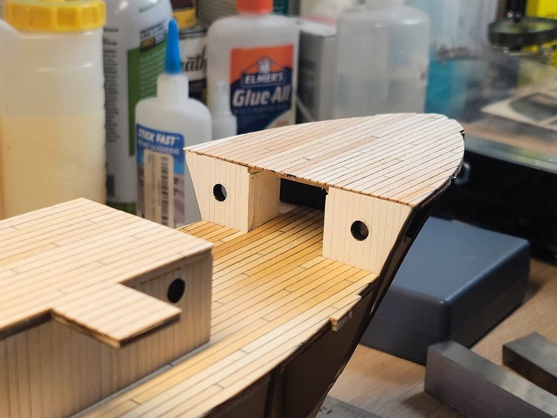
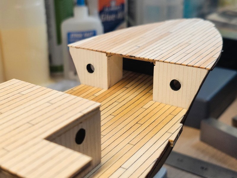
I didn't actually wait to sand and continue on the aft companionway so here it is complete after the stain has dried.
I still need to paint the inside passageway walls, and I did end up increasing the height of the windows. The structure was built to sit directly on the deck, not on top of the decking that still needs to be glued on. I'll be adjusting for this fact once I begin the decking.
- HakeZou, clearway and iMustBeCrazy
-
3
-
48 minutes ago, iMustBeCrazy said:
The aft companionway would appear to have two doors, the first two shots aren't conclusive but the third shows the left door still hanging:


And a brightened version of your last shot:
Ah yeap, two doors. Thanks for the pics!
-
19 hours ago, clearway said:
Its an old billings stovepipe fitting altered to look more accurate- so the rain hat is turned brass from the fitting with 3 pieces of brass wire added. The pipe is 35mm from the deck with the rainhat 5mm above that- pipe diameter is 4mm.
Keith
Thank you!
Continuing to work on deck structures, I put together the chests rather quickly. I saw someone use the brass stanchions as hinges and really liked the way they looked, so I did the same.
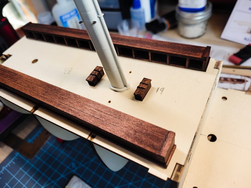
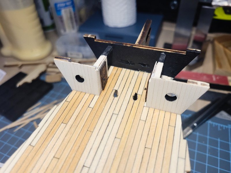
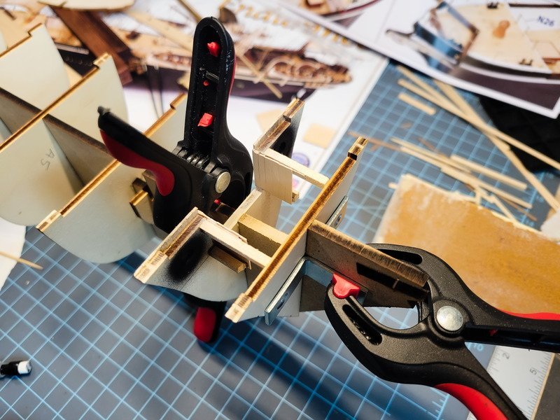
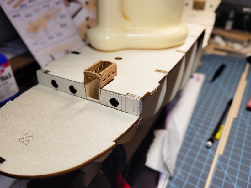
Next up I moved ahead with gluing the bulkheads on to the MDF false keel. I used some steel corner brackets that I ensured were 90* to clamp the bulkheads in place.
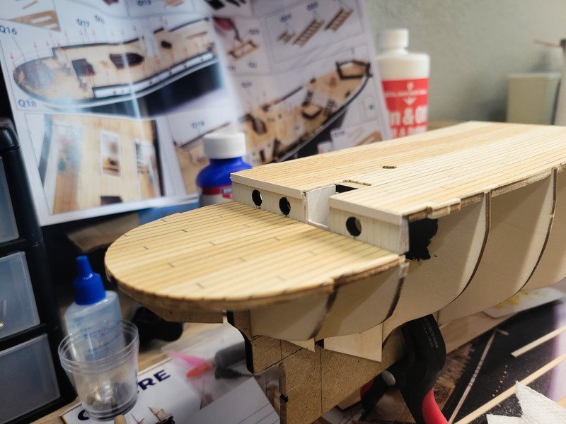
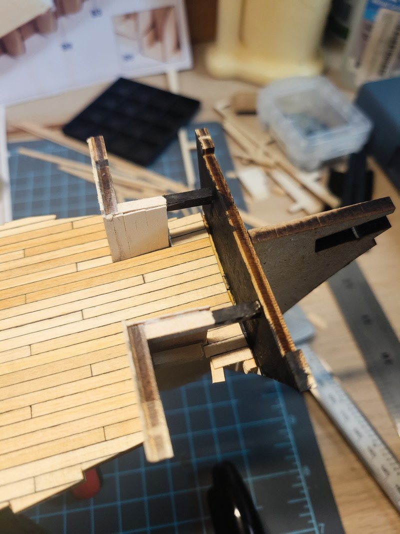
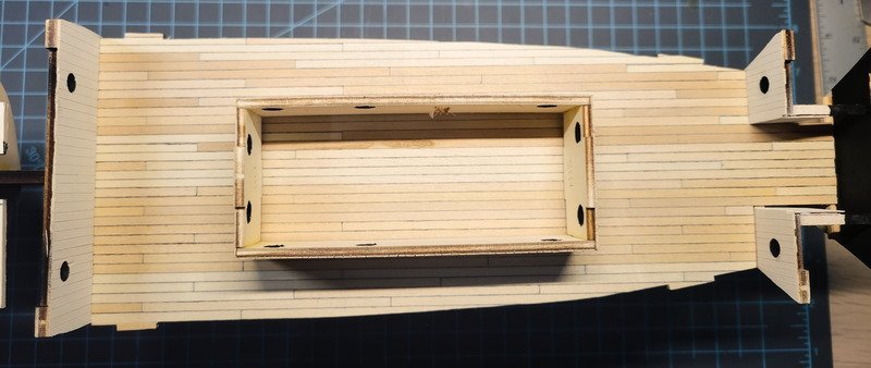
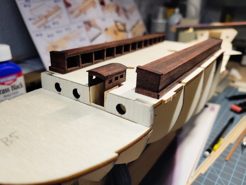
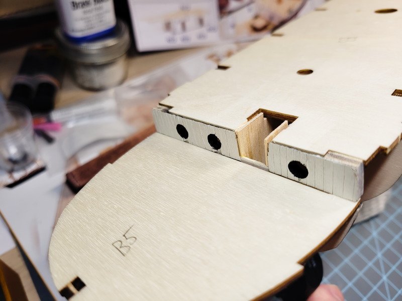
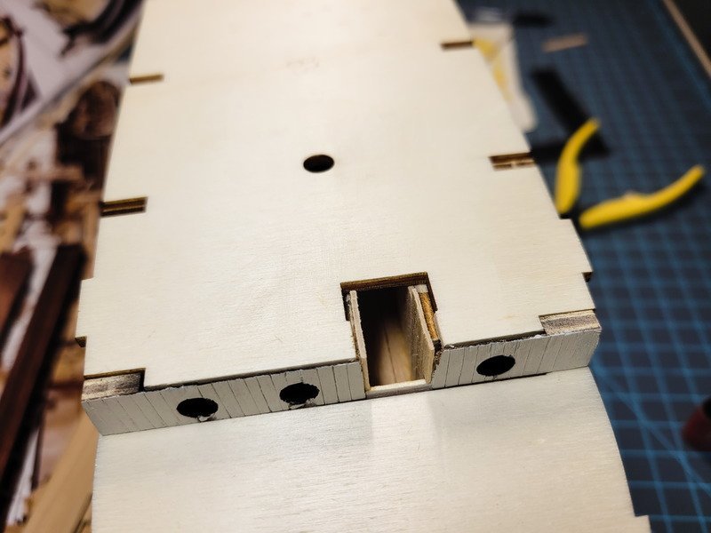
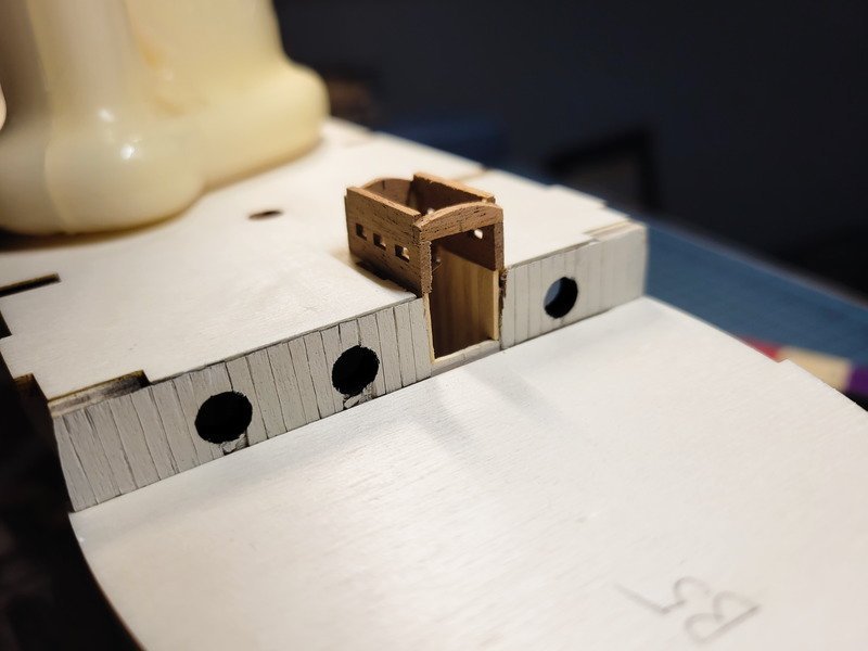
With the bulkheads now secure I started working on the aft companionway. Since I'm changing the hatch, I decided I wanted the companionway door to be open, with the passageway detail visible.
This is another change from other models I've seen: the aft companionway appears to only have one door in the pics. I've only found two pics, both of which are already in this thread, that show this opening, and the door appears to cover the entire space.Edit: There will be two doors.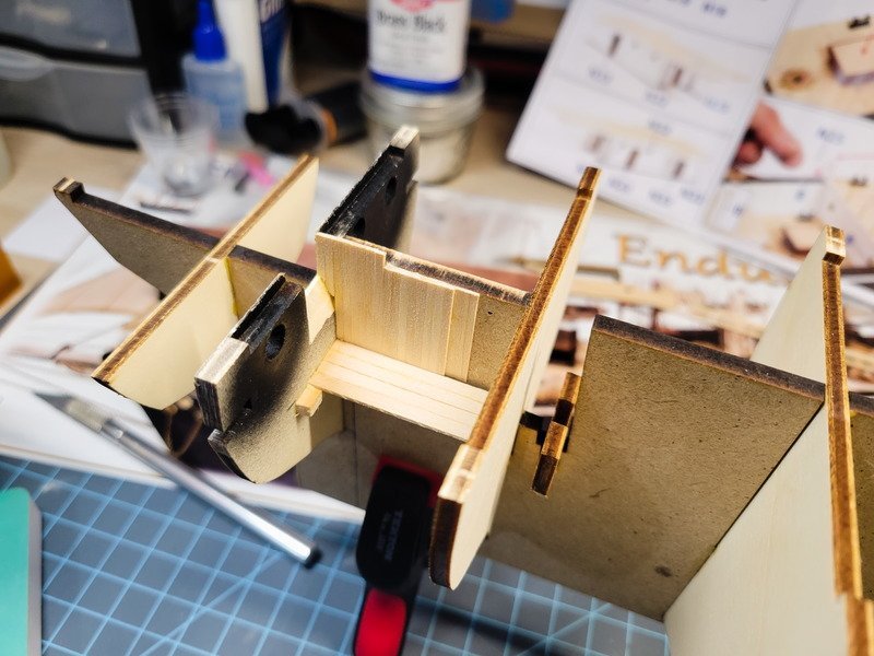
I chiseled out the left bulkhead in the above pic so it doesn't appear so thick when viewed from aft. I then planked the keel with 0.6x5mm decking veneer so the opening in the bulkhead was flush with the keel. The inboard wall was planked with 1.6mm basswood, and then I planked the floor with the 3x1mm that comes in the kit. Finally the outboard wall was framed with spare plywood sprue, and planked with the same 1.6mm basswood.
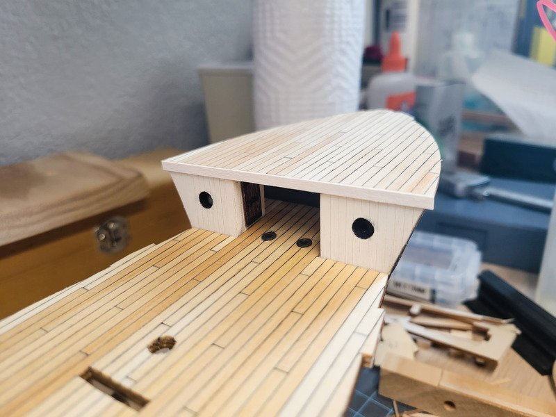
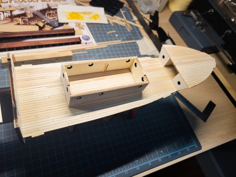
I still need to paint the new walls the same white I'm using everywhere else. I'll be including a 0.5mm brass rod hand rail, but won't install it until I decide which side of the ship will be displayed. Next was planning the structure. I decided on 3.3x1.5mm mahogany strips, with slots filed out for the windows. I used a $10 micro engraver to remove most of the material, then needle files to square up the lines. All under magnification.
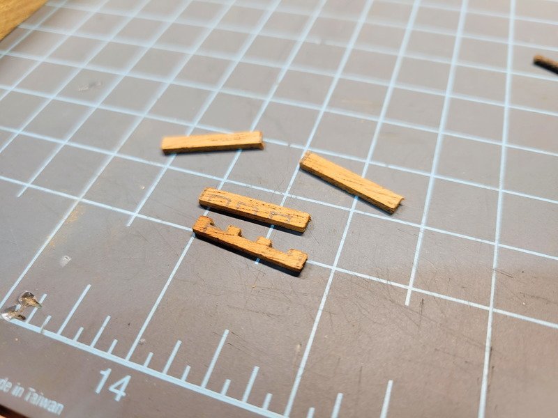
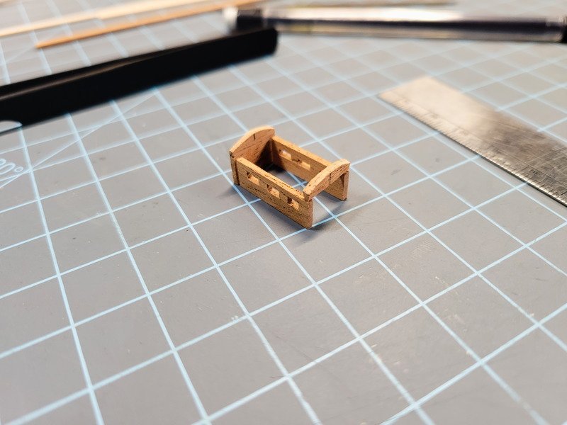
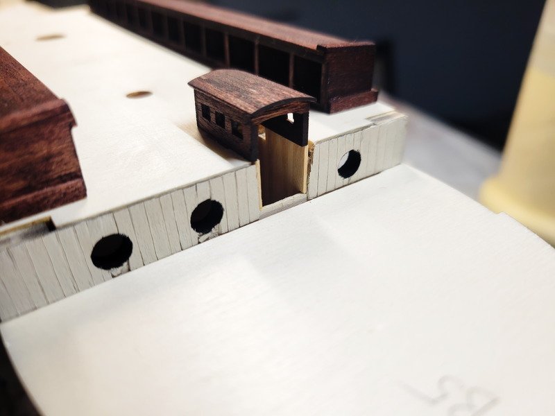
It's not fancy, and doesn't have joints like it probably should. The structure is ~8mm tall by 20mm long by 10mm wide. The slots are 4mm long, with 2mm between. After adding an additional strip to the top of the walls, and gluing it all together, we have this:
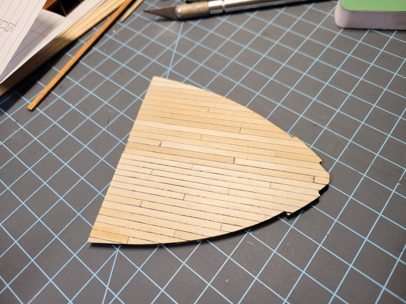
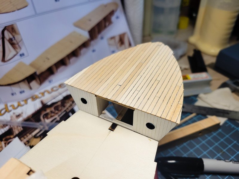
The glue will need to dry over night so I can sand it tomorrow without fear of it breaking apart. I'll sand down the roof to match the front and the back, then install planks and stain it. It'll have some trim to cover up the transitions as well, like the damage to the starboard side of the doorway on the aft bulkhead. I'm also going to sand the proper curve into the top of the doorway, but want it to be glued to roof planks first. Looking at the pics, I may need to increase the height of the windows so will consider that tomorrow as well.
Finally, I remembered the found-wreckage video showed a fly-in shot to the aft deck. I wanted to get more reference for the structure. In doing so, I also noted the confirmation, finally, of circular pin rails on the masts.

I have spent many hours going through videos and photographs trying to determine what the rigging actually affixed to. Were there actually eye bolts in the deck? Why? It seemed that spot was blocked, conveniently, every time I thought I was getting close to discovering it. I'm excited to finally spot this detail.
Thanks for coming in!
- HakeZou, iMustBeCrazy and allanyed
-
3
-
53 minutes ago, Snug Harbor Johnny said:
Once more, some pictures new to me ... ferreting out "Getty" branded images (or any others that really are in the public domain - due to prior publication under the old laws - but have been since "copyrighted" by various organizations in possession of them). I have a collection of 'turn of the 20th century' post cards (most of them printed overseas, often Germany) with no copyright information on them (being ephemera at the time) - ergo they were public domain from the moment they hit the streets. YET, I'm seeing the same images on various internet sites where the holder has 'slapped' a so-called 'common law' copyright on the image ... hmmmm, perhaps they imagine that whatever spots, postmarks, folds, tears, etc. make them unique and fair game to anyone who wants to try and claim them as theirs. Yup, I've seen multiples of the same postcard in multiple sites ALL 'claiming' ownership.
Not to worry, all one has to do is Photoshop out blemishes, foxing, postmarks, etc. and you have then created your own 'new' image ... and no would-be hoarder can lay claim to it.
You have good points Johnny. I don't know if my attitude is the right way to think about it, but I've never cared about copyright because I'm not profiting for the material I am referencing. I'm not profiting from the material I produce, either, and have zero interest in doing so. I don't know who owns the images I post, and have no inclination to find out. Getty seems to have the majority of images, but I've also going to google images and searched different key words to find the lesser-known images I've posted.
27 minutes ago, clearway said:the stovepipe is for the galley stove and is fitted towards the front of the ritz. The galley occupied the port forward side and an entry way/ staircase leading below decks to starboard with the "ritz" taking up the rest of the room leading astern- well i aint tearing my ritz off and adding the square window now😁- On the pre conversion plans i have for Polaris the plans show 3 square windows each side on the ritz- and even the the ones on the quarterdeck are square.
Keith
I'm with you Keith; while I'm striving for historical accuracy I mentioned in my first post I'm only shooting for 90% or so. The square windows in the ritz don't really interest me enough to cut them in and figure out trim, or suggesting glass, etc.
Do you mind providing some measurements on your stovepipe? It looks to scale, so what's the height from the deck and the diameter of the tube you used? Also, did you make the top bit? I've been puzzling over how to create that as I don't have any brass sheet (other than PE sprue, if you call it that).
.jpg.ad557eee6c790c34d500db3fc74bb3cb.jpg)
.jpg.200a8488efa87b809d57d27fc463dcb2.jpg)
.jpg.67ad0a98a5ee35da4ab8431b2835b524.jpg)
.jpg.ed26d2d97c3b8b710e2a65e34332c512.jpg)
.jpg.4da1d3257c9dc64be829f4d8f088951a.jpg)
.jpg.2150c859a40899d68e16028380260292.jpg)
.jpg.3f8feaa8bce91698692cecd81c9397e5.jpg)
.jpg.df1b0d756e2d893bd4e65c958922d6c4.jpg)


Endurance by theoracle09 - OcCre - 1:70
in - Kit build logs for subjects built from 1901 - Present Day
Posted
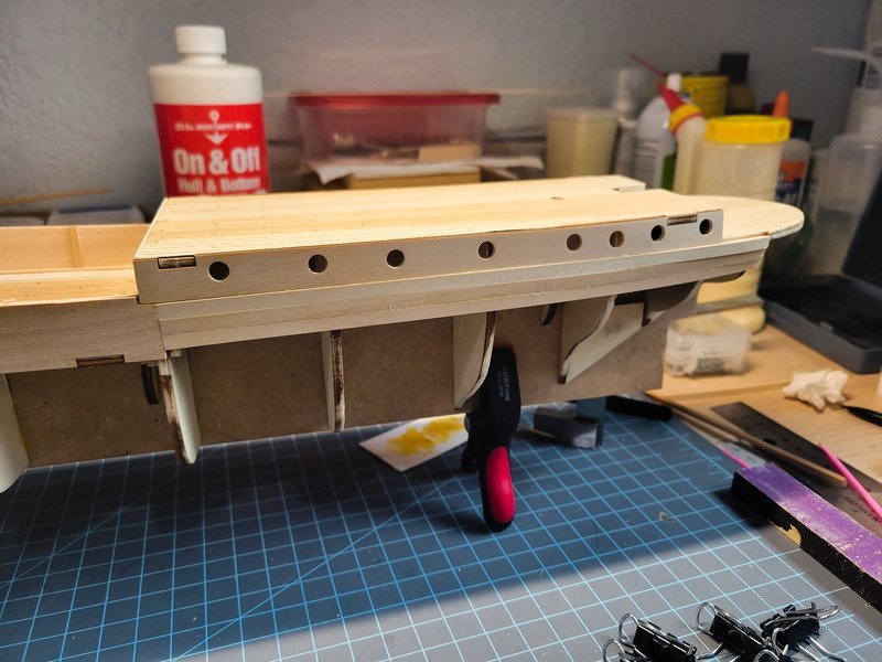
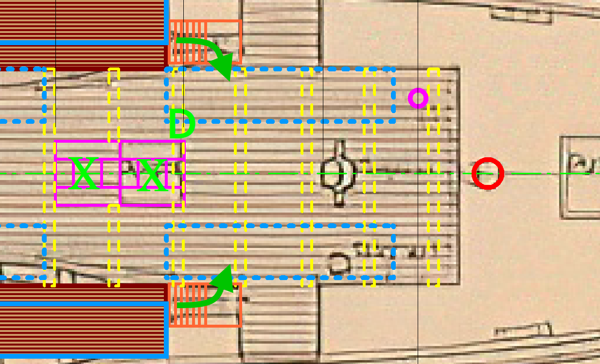
Does anyone have any reference for a windlass that may have been installed under the anchor deck? As I've been planking, I've been pondering the anchor chains dropping through the quarter deck, and building a windlass and installing it would have probably been better off with the anchor deck off.
I've attempted to search what they'd look like around 1911/1912 but haven't found anything concrete to use to model off of. As the anchor deck is on top of it, it wouldn't be visible unless viewing from an extreme angle, but that's precisely why I want to include it. No one will know it's there unless they look under that deck, and with the closet and door details it'll really round out the area I think.
In the plans pic above, does it say "Steam Windlass"? Until I zoomed in to take that screen shot I had assumed it said "Stem Windlass". If the windlass does run off of steam (I know nothing about windlasses by the way, even what they do without steam) could that explain the steam pipe running on the ceiling of the 'tween decks area we're now calling the Ritz?
Thanks in advance for any pointers!