


Rick01
-
Posts
637 -
Joined
-
Last visited
Content Type
Profiles
Forums
Gallery
Events
Posts posted by Rick01
-
-
Thanks - next stop my library I think. :-)
Rick
-
So it would be normal with a cutter built to naval specs to have this area boarded in? As you may have Guessed my knowledge of ship construction is near zero so I'm using contemporary models plus King's own illustrations of the Mermaid to build my model and the more I do the more it seems the kit instructions have deviated from what would be correct.
Rick
-
Next question whilst I'm working on the deck area of my model. This section of Ollie's build shows a series of "frames" as required by the plans http://modelshipworld.com/index.php/topic/3958-hm-colonial-cutter-mermaid-by-ollie-modellers-shipyard/page-16?hl=mermaidMy problem here is that all the models I've looked at of cutters built during the same 1800 period in the UK NMM do not show these frames. Who's correct?
Not from NMM but a good clear shot anyway http://www.modelships.de/Museums_and_replicas/Science_Museum_London/gIMG_0584.jpg
Rick
-
Thanks again - as my knowledge of ships is limited to port, starboard, bow and stern your advice has been very helpful.
Rick
-
Wayne - thanks for the high res. shot. It has helped answer my queries. For some reason I'd not found that particular link when looking for information.
Rick
-
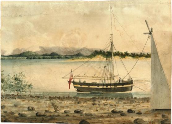
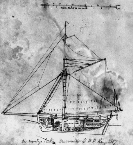
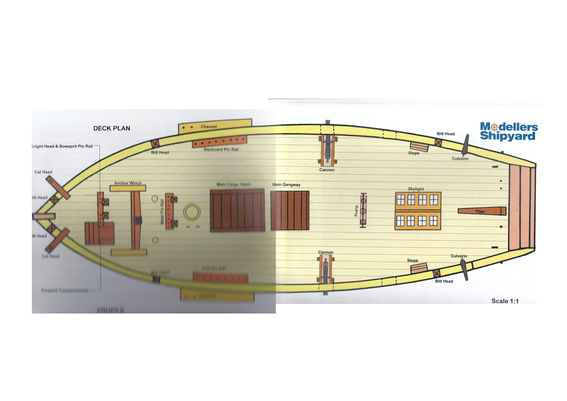
I've already got a query going in the rigging section but now have a point to clarify re fixtures and fittings. I'm basing everything on the sketches by King rather than Modellers Shipyard plans as these appear to be lacking in accuracy in some areas.
In this sketch from left to right we appear to have a forward companionway, pinrail, windlass tight up against pinrail and then possibly ship's oven. Behind the mainmast is the main cargo hatch, gangway, sky light with the ship's boat stored behind, then lastly possibly the pump.

The plans however seem to have gained a "main pinrail" unless it's hard up against the mainmast in King's sketch, reversed the pump and skylight and removed the ship's oven.

I understand the oven is moveable so that's not of concern however any comments on these points would be appreciated.
Rick
-
Thanks for the picture - better than the one I have. It has raised another couple of questions however. First the oven would appear to be exactly where the anchor windlass should be situated and second the anchor attachment would appear to be chain not rope. Any one like to comment, particularly over the windlass situation.
Rick
-
Not exactly something King would get wrong is it.
 Looks like I'll be making some VERY small hooks later in the build and I had no intention of kit bashing this early in my career.
I thought it may be a stove but didn't realise they were "mobile" so looks like an Aussie BBQ isn't anything new.
Rick
-
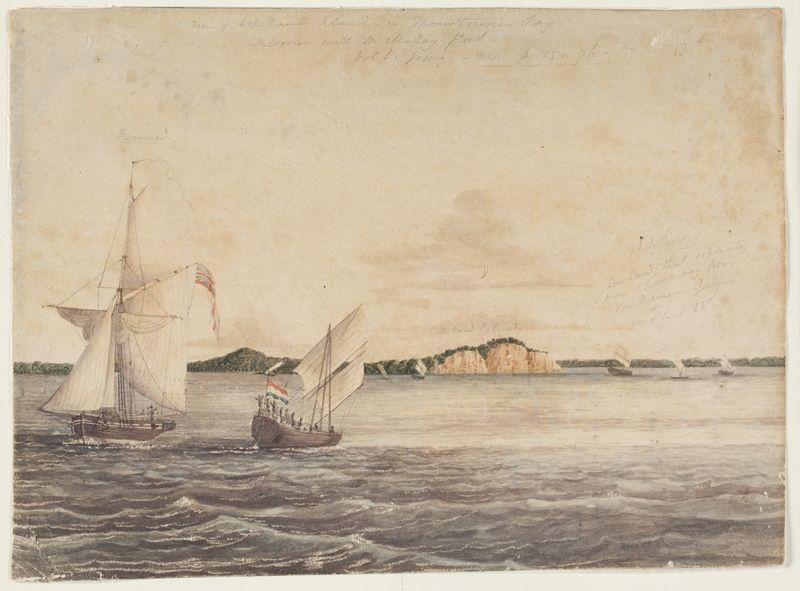
This watercolour seems to show hooks on the second and third visible blocks counting from the left. Blowing it up in Photoshop makes them appear quite clearly as a hook shape below the block.
Just as a matter of interest this also shows something looking like an F1 air intake reversed on top of the anchor winch!
Pittwater News has the best copy see http://www.pittwateronlinenews.com/bungaree-was-flamboyant-by-neil-evers.php
Rick
-
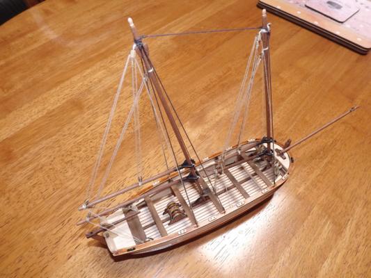
I'm basically working off those for details of rigging etc. rather than the plan booklet supplied. I also noticed that the blocks controlling the upper boom/gaff? seem to attach via hooks rather than having been bound to it. In this case the eyelets that they attach to would either have been bound to the gaff or bolted through it at a guess. I wouldn't have thought the latter however as that would seem to weaken it quite considerably.
Rick
-
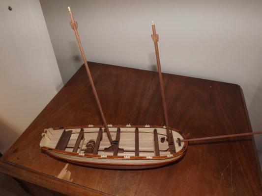
OK next rigging query (and unless it's a problem I'll keep any rigging type queries going on this thread). The mainsail attaches to the mainmast via a number of large metal rings, when the sail is removed I assume that the rings stay on the mast, so if I complete my model under bare masts I assume that to be somewhere near correct these rings should still be apparent sitting on the yoke that connects the boom to the mast (excuse the terminology if it's incorrect).
I'm nowhere near this stage yet but I prefer to have an idea of what I'm doing well before I get there and find I've got to tear something down because I forgot to ask the question.
Rick
-
Thanks John - cleared that up nicely. Pity Modellers Shipyard didn't look at King's own sketches of his ship when putting the model together.
Rick
-
Thanks - knew there would be a simple answer. So displaying the finished model without sails would mean that the only evidence of this would be (and I'm guessing here) a spare block near the top of the top mast and a similar spare block at the end of the gaff.Would any rigging be run through these and if so where would they be tied off? Or can you point me to a simple (layman's) instruction manual?
Rick
-
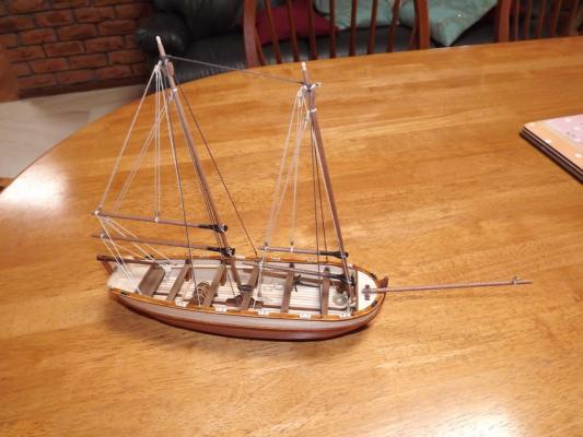
I've just opened my Christmas present and am attempting to research a few items as I start my build. Obviously I've been over Ollie's build http://modelshipworld.com/index.php/topic/3958-hm-colonial-cutter-mermaid-by-ollie-modellers-shipyard/?hl=mermaiduntil I almost can repeat it by heart. However I am still puzzled by one item and that is the yard/spar/boom whatever attached to the top mast. Ollie after discussion by pm has it attached centrally and notes that it may be a "flying" yard which I won't dispute as I have pretty well zero knowledge of ship nomenclature. However from studying King's own sketches/water colours it appears that it is loosely attached possibly via block behind the top mast and at a point 1/3rd along its length.

This is born out by some models and sketches from the NMM (UK)
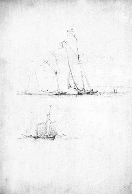
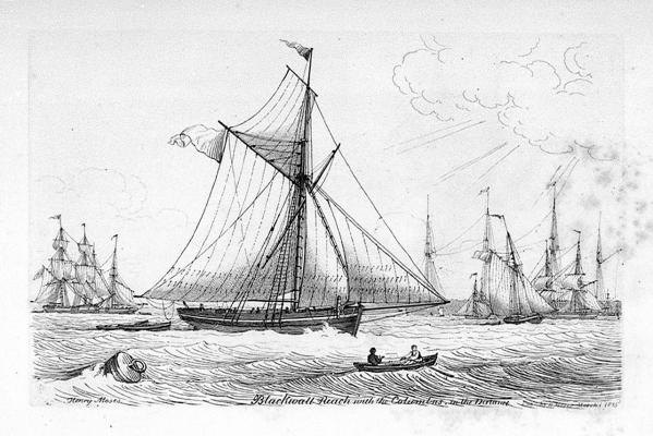
So - how does one rig this or is it something that would only be brought out when you wanted to go really really fast!! If so where would the yard be stored on or below deck? Just as an aside I saw that Ollie was querying the cannon positions, if you look very closely at the first picture you can see what appears to be a single cannon run out at the rearmost cannon port.
Rick
-
-
Well I've just received some extra rigging from AL - however it's from a different dye lot and is noticeably different from the previous lot. So, the only solution will be to check how much they've sent me and hope that there's enough to re-rig all the stays etc. Didn't really want to do this but if it's going to look good then so be it.
Meanwhile I have built a case for it so the time waiting wasn't all wasted.
-
I've almost completed the rigging and other fittings now but have come to a stand-still due to a shortage of rigging. AL have supplied about 40 cm less of the heavy (dark brown) thread than is needed to complete this, however I have been in contact with them and they are sending a further supply out. The actual rigging illustrations/instructions really are pretty basic and I've had to use the box top illustration plus internet searches to get something that looks near correct. Not overly happy but it'll do for a first time!
Rick
-
Newbies question but if you don't ask you wont find out.
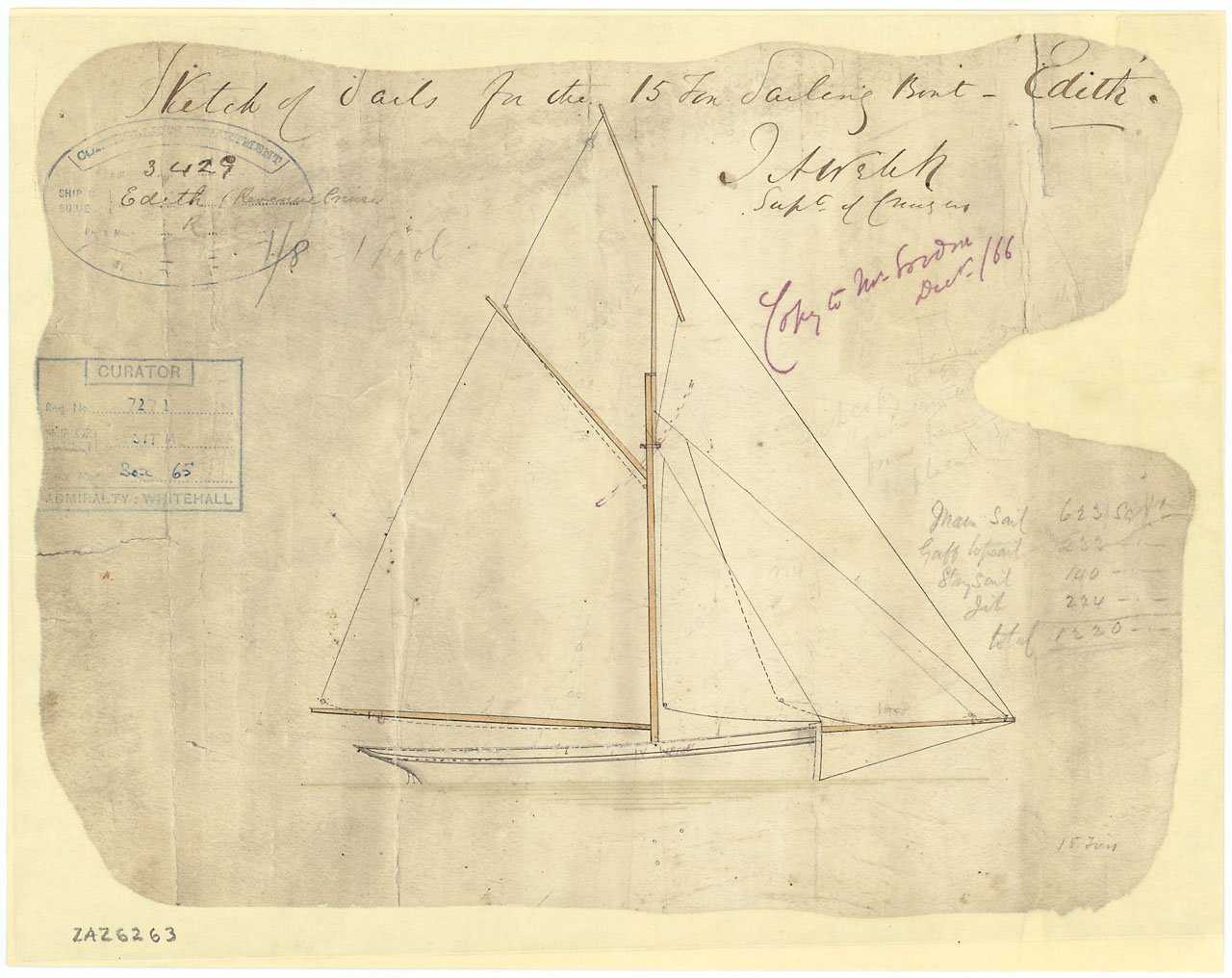
I'm building the AL "Endeavour's Longboat" and have arrived at the rigging. Their instructions are as clear as mud for a beginner but with the help of the 18th Century longboat build here, plus their box illustration I've got a fair idea of what goes where (and why!!). However the instructions just say to "tie off to mast/eyebolt". All very well but this leaves no method of tensioning for the stays were this the real thing. Personally I'd have expected the stays to be looped at the top of the masts and a hook/turnbuckle arrangement at the eyebolt. I know the latter would be pretty hard to model at this scale but a plain hook should be possible. So what do I do - just tie it all off or at least try modelling a small hook at the eyebolt end?
Rick
-
Few more items fitted up and more grizzles about the instructions. Boom brackets - no measurements given as to where they sit on each mast and no side comment that they'll fit better if you file a groove in the side against the mast, so I've had to look at the box illustration and make an inspired guess for positioning. Got it roughly correct I hope but having taken them down twice I'm not doing it again. Trysails (?) you'll need to file the jaws flat internally to fit the booms.At least they did give positional information for the lugs at the top of the masts. Next the eyebolts - instructions suggest 1 mm dia. drill holes - do this and they'll fall straight out again. A 0.5mm drill is needed here. Next item will be the rigging - again not the best instructions but hopefully the 18th century longboat here will help.
Rick
-
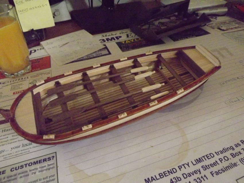
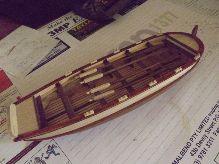
Now starting to fit it out. For anyone who builds this I'd suggest that steps 9 and 10 in the manual be ignored until you've fitted step 11 - boarding and thwarts, the gunwale covers really get in the way when trimming everything to size. So steps in this order 8, 11, 9, 10. Instead of the single pin resembling a marlin spike I've chosen to make a set of thole pins with reasonable success - cutting down cocktail sticks 'til they're about 1mm thick is somewhat time consuming but I did get there. Oars were reasonably easy but I do need to make some sort of jig in order to centralise drill holes in future as near enough isn't quite good enough when you know where your mistakes are.


Feel free to comment if anyone wants to.
Rick
-
No problem with hijacking - I've basically got an answer to my part of the query so any other heritage questions remarks are welcome - let the thread run and go where it will, :-)
Rick
-
Thanks for that Bob - I'll try and hunt up a copy with the plans still intact.
Rick
-
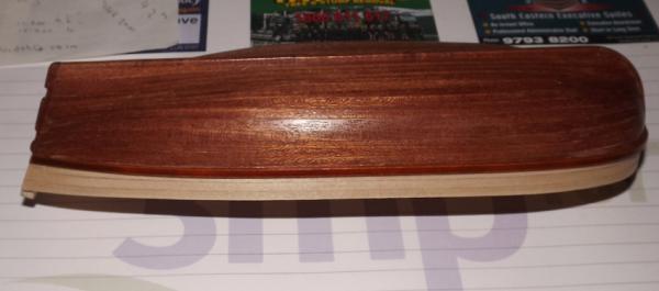
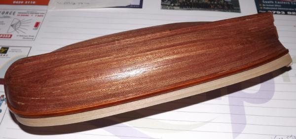
Well planking is now finished to a reasonable level. I didn't have to fill with much home made wood putty although fitting the last couple of planks each side was difficult and a couple of stealers were used. A water base satin finish clear coat has been applied to the exterior to preserve it from grubby fingers whilst working on other areas.
Rick
-
Perhaps a poll of other Australian members would show the level of interest in a project regarding the Enterprize. At my current skill level this is just academic but a little further down the track it would definitely interest me.
Rick


HM Mermaid fittings.....(Edited by admin)
in Discussion for a Ship's Deck Furniture, Guns, boats and other Fittings
Posted
Thanks - I hadn't picked up on that set of photos.
Rick