


ccoyle
-
Posts
8,611 -
Joined
-
Last visited
Content Type
Profiles
Forums
Gallery
Events
Posts posted by ccoyle
-
-
The Digital Navy V108 kit does not, with a few exceptions such as the bridge wings, include railings for the model, nor does it include any templates for railings. But hey, it's a free model, so we won't complain too much, right?
But that doesn't mean you can't add railings. Railings add a lot of subtle visual appeal to a card model, and there are four ways you can add them: 1) made from paper, much as the bridge wing railings (these create the illusion of open railings); 2) after-market laser-cut railings (to my eye these are overly stout-looking, but they come pre-cut obviously, and that's worth something); 3) photo-etched railings (the best-looking and also most expensive option); or 4) thread railings. I'm going to show you how to do option #4.
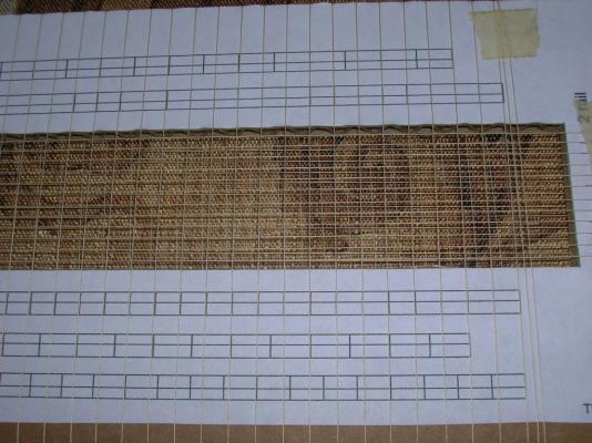
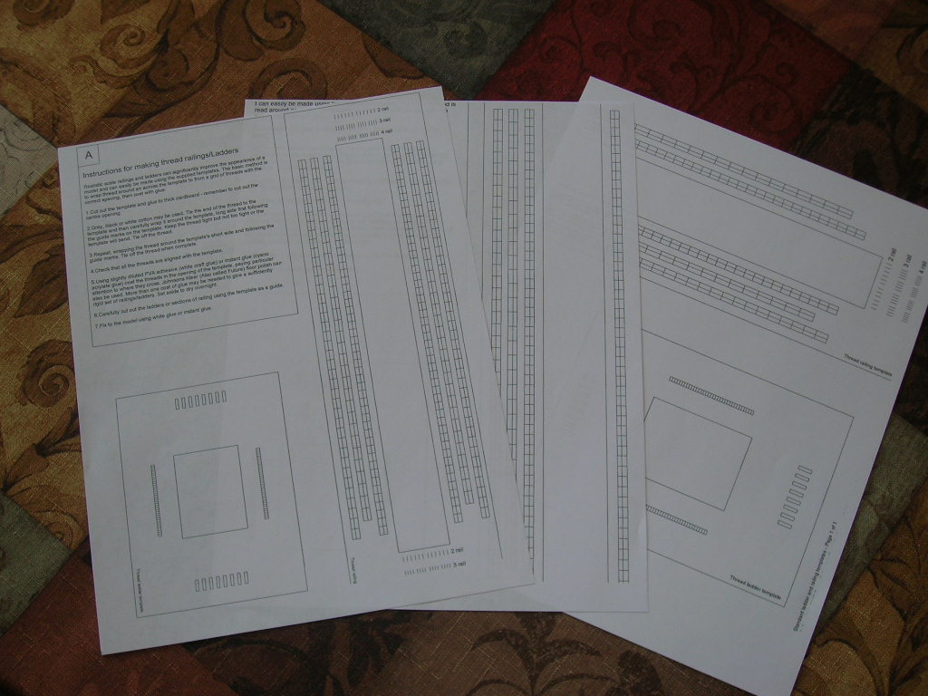
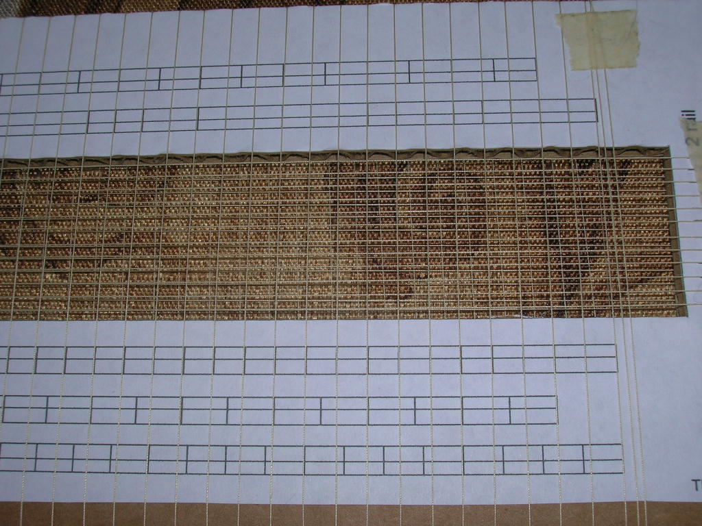
Start by downloading the free railings template at Paper Shipwright. You'll have to go through the whole checkout procedure, but relax - you don't get charged anything for the transaction. The Paper Shipwright template is in 1/250 scale, so you'll need to scale it up for 1/200 by printing at 125% of the original. At that size, you won't be able to print the template on one sheet of paper. What you do absolutely need is both ends of the template; I managed this by printing two copies of the template in landscape mode.
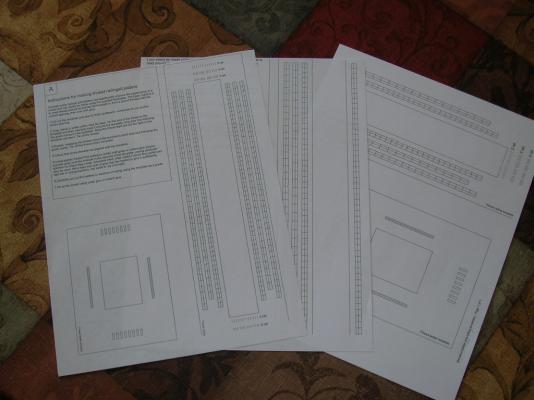
(L to R: full-sized template, middle portion enlarged 125%, two copies at 125% printed in landscape mode.)
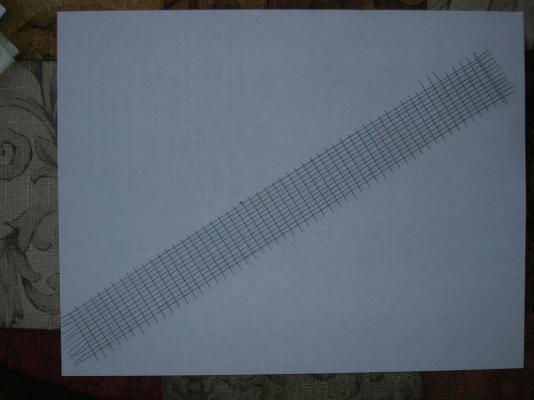
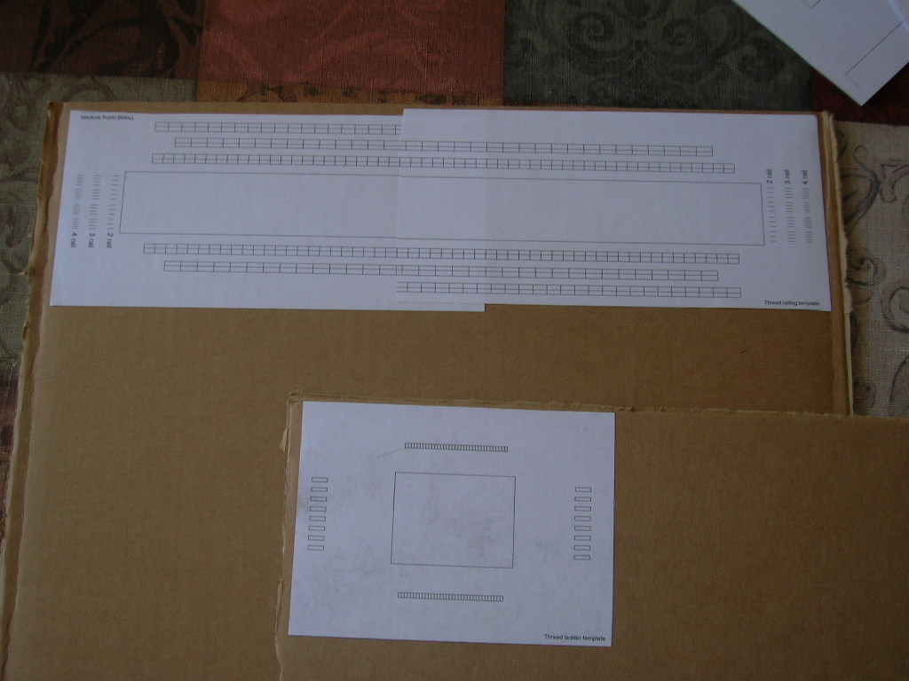
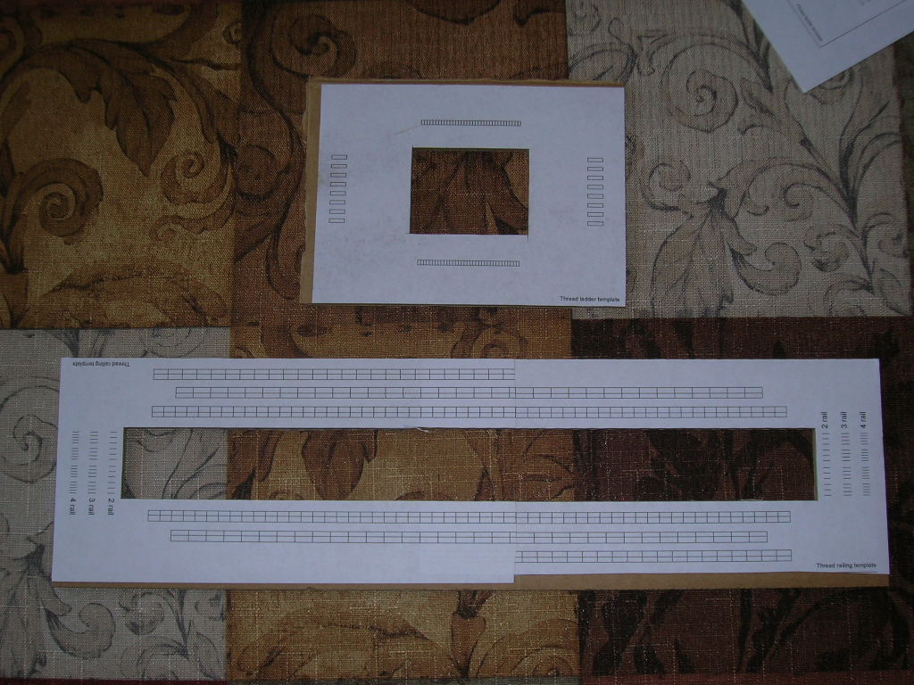
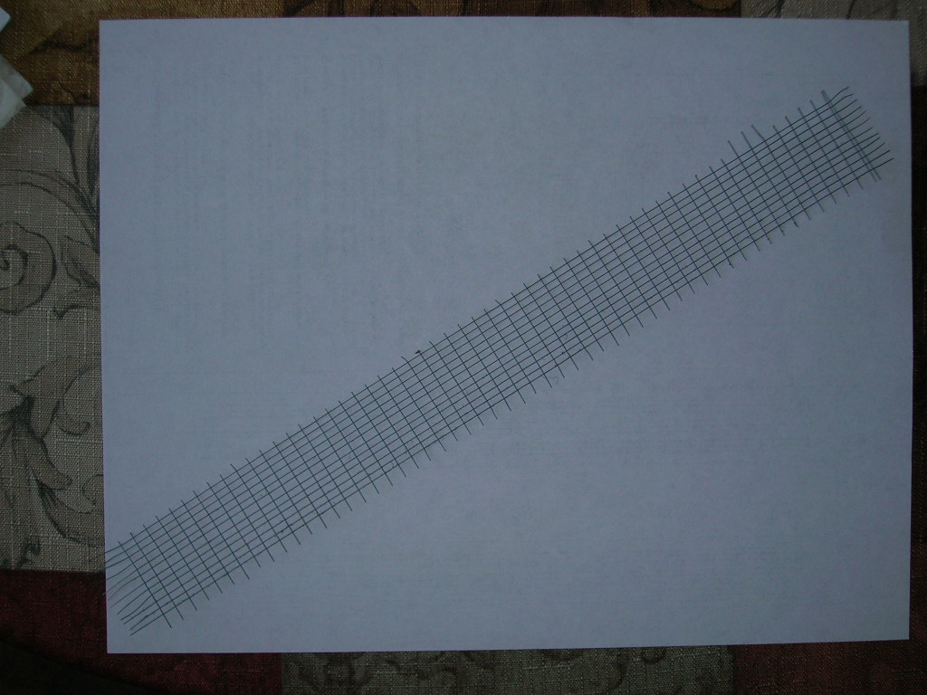
Next you'll need to glue the templates onto some heavy-duty cardboard. I found that a case for liquid fabric softener worked well -- it's very rigid, because of course liquids are heavy. Use spray adhesive to glue down the templates. In this picture you can see that I've spliced the two landscape-mode copies together to make a single template. There's also a thread ladder template, which I won't be demonstrating, but which works in principle exactly like the railings template.
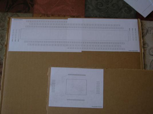
Next, remove the center portion of the template.

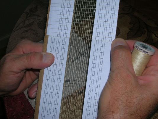
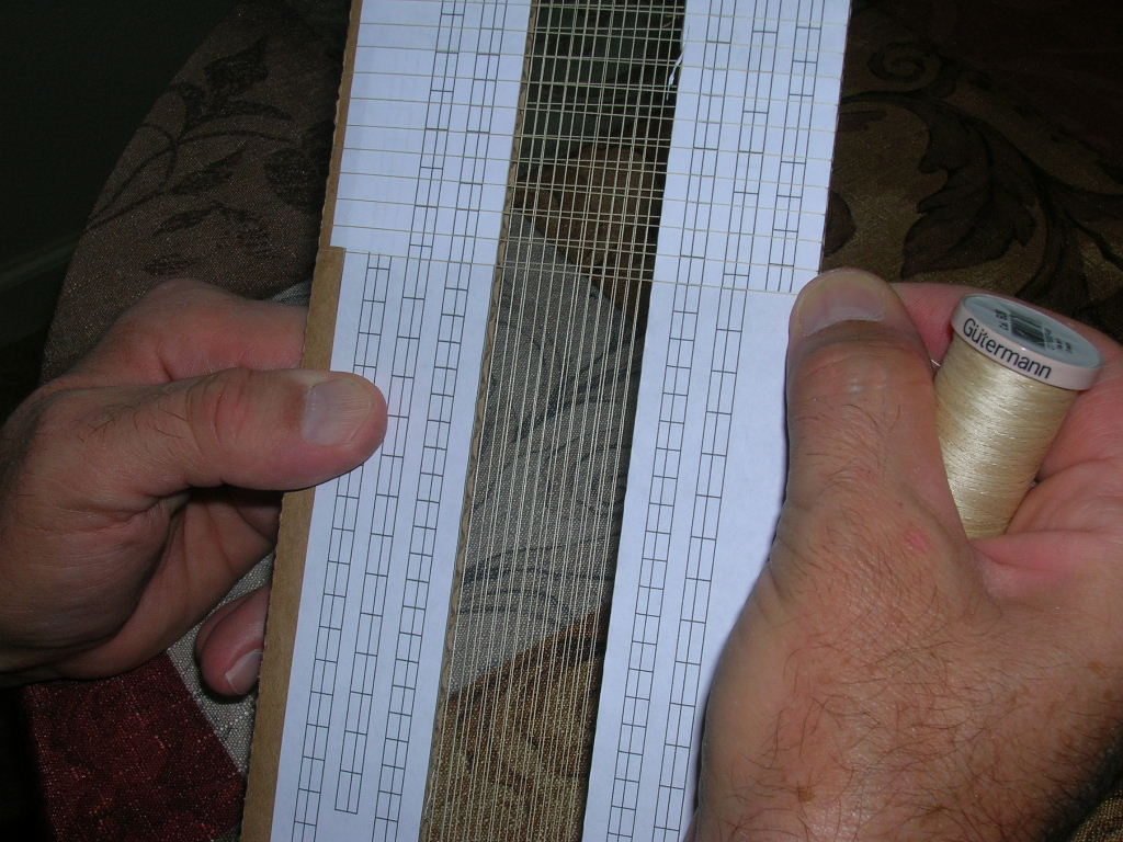
You're now ready to start wrapping thread. I use quilting thread, but regular thread will also work.
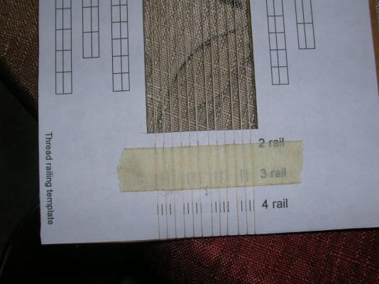
The template works like this: At each end are tic marks labelled two rail, three rail, and four rail. These are the marks you will use to align the railing threads. Notice that the two-rail marks actually consist of three marks - the bottom 'rail' is actually used to mount the railing to the model and doesn't count as one of the real-life rails.
On opposite sides of the template are drawn railings with the stanchions spaced at different intervals. The smallest interval is about 5.5 mm. The stanchion locator marks on the model are 6 mm apart. I don't know about you, but I'm not going to nit-pick over 0.5 mm, so I used the 5.5 mm spacing.
Start by wrapping the rails first. Use some tape to secure the thread right on top of the tic marks. Go ahead and use all four sets of two-rail marks - you'll get four lengths of railing as a result.
When the rails are done, cut the thread and secure the end with tape, taking care to ensure the thread stays taut and properly positioned. Next, add the stanchions in the same fashion. You have to kind of train yourself to concentrate only on the stanchion interval you want to use, otherwise you wind up with irregularly spaced stanchions. You can cut off the other stanchion spacing guides if you find them too distracting.
When all the rails and stanchions are wound, it's time to secure the joints by giving the entire railing set a coat of diluted white PVA glue. You can also try medium-cure CA, which will make the railings stiffer. I didn't use CA this time around because my bottle of medium-cure is on the old side and is more like medium-slow, which is too viscous for this job. Before brushing on the glue, I find it helpful to add some tension to the railings by sliding a piece of dowel or strip wood under the rail threads at either end of the template; this will push the rails up and against the stanchions. After the glue dries thoroughly, you can paint the railings in any manner you choose. I use gray spray primer. One thing to take note of here is that any thread will have some fuzz on it. Quilting thread has less fuzz, but it still has it. Spray painting causes build-up on the fuzz, and too many coats can make this build-up unsightly. It helps to pick off as much of the fuzz as you can before and/or after painting.
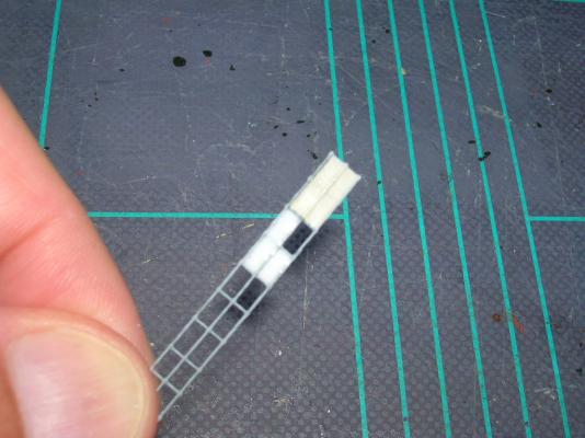
When the paint is dry, you can remove the finished railings from the template. Here's my set:
At this scale and template length, I got about four feet of railing, which should be more than enough to do the model, even if I mess up on some and have to try again.
-
It's been a while since I built this kit, but I do remember having difficulty with that lower plank. As I recall, the amount of bending at the front was particular severe. I believe i got around the problem by making an approximately one inch long cut in the plank parallel to the keel and about half-way up the the front edge. Once the plank was glued and dried, I filled and sanded the resulting small gap in the plank.
-
Believe it or not, there's just a few things left to do on the basic structure.
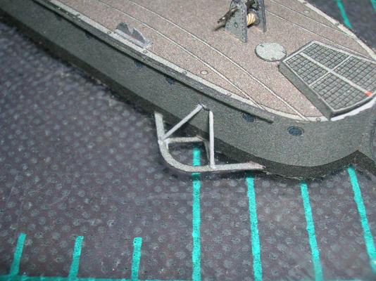
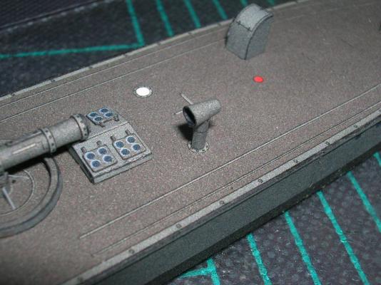
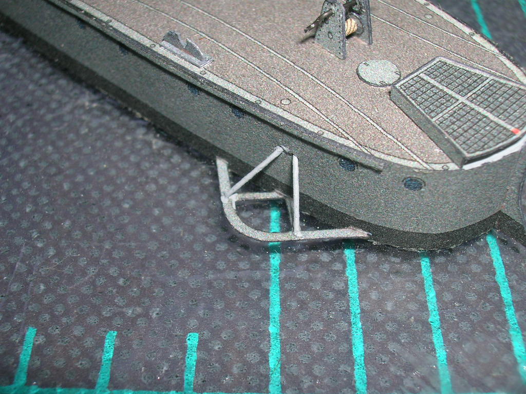
Something we didn't add way back during the hull construction are the propeller guard struts. Same as we did with the bridge supports, start by carefully punching holes in the hull above the guards (there are locator marks). Cut small pieces of wire slightly longer than needed for the finished strut. Insert one end through the hull and pull the opposite end down onto the propeller guard. Secure it with CA. When the glue dries, the loose wire ends at the hull will allow you to move the guards up or down to get them level with the waterline.
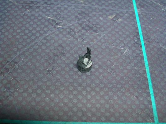
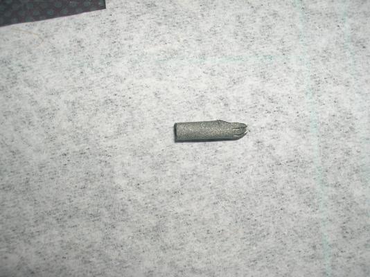
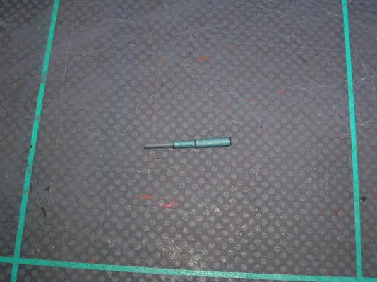
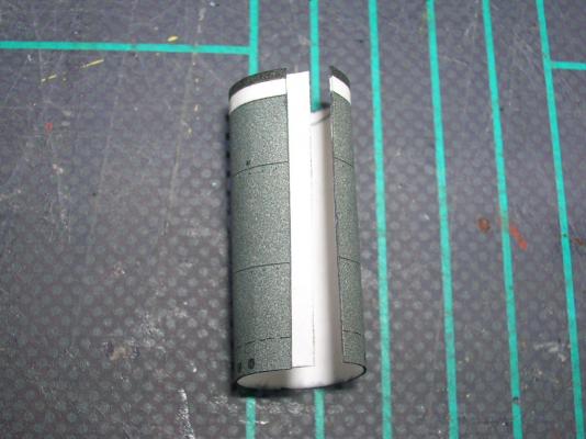
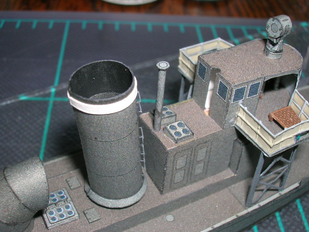
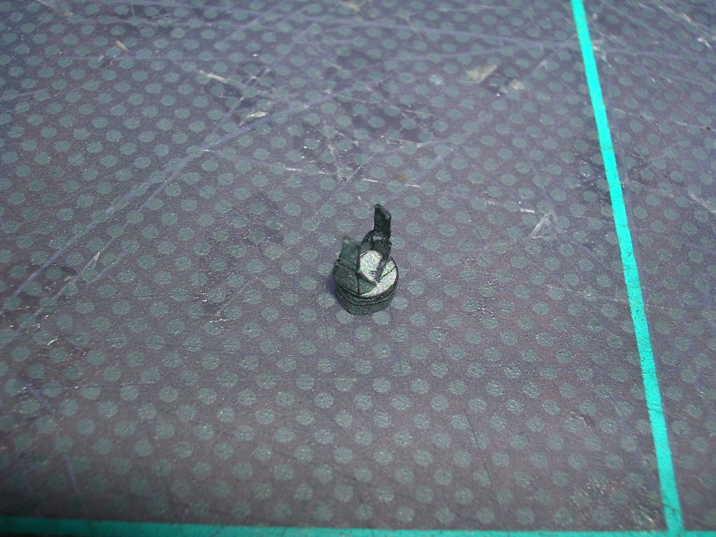
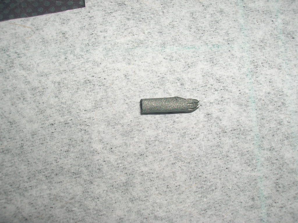
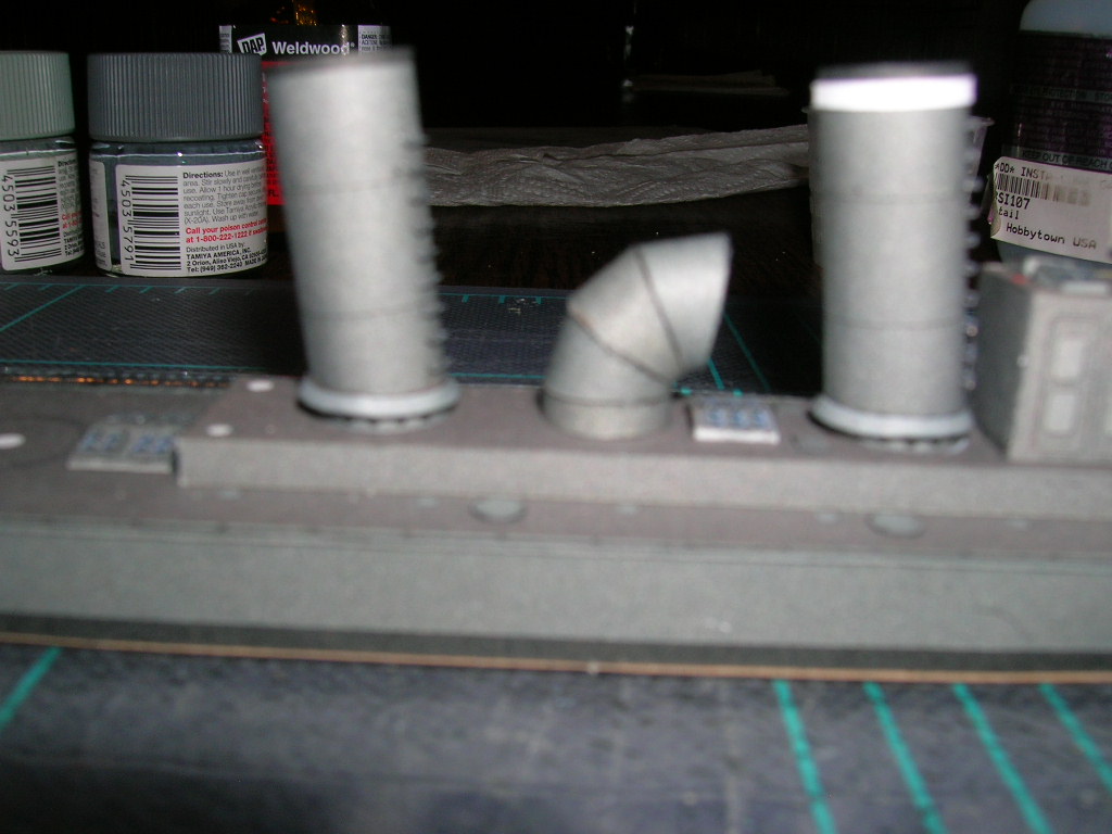
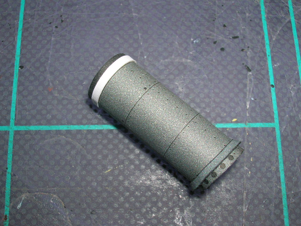
The galley stack (61) is one of the last parts for good reason -- it is easily knocked off the model if it is mounted earlier. A long, cylindrical part like this can be made from paper alone, but I prefer to give it some more substance by rolling the 20# bond version of the part around an inner core, in this case styrene rod. Start by tacking the glue tab side of 61 to the rod.
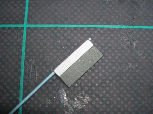
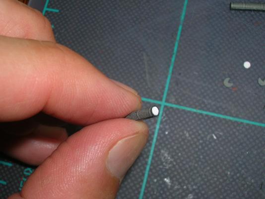
When that's dry, simply roll up the remainder of 61 onto the rod and add the cap. Notice in the previous picture that I left a small stub of styrene at the end of 61 - this will be a locator peg for mounting the stack on the model after drilling out the locator mark on the roof of the galley.

(You may notice in this photo that two of the photo-etch rungs have come off the forward stack. They disappeared into the ether and have not been seen since. I had to cannibalize two replacement rungs from the PE fret.
 )
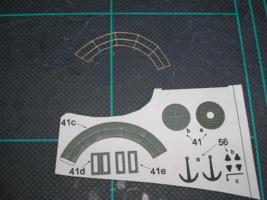
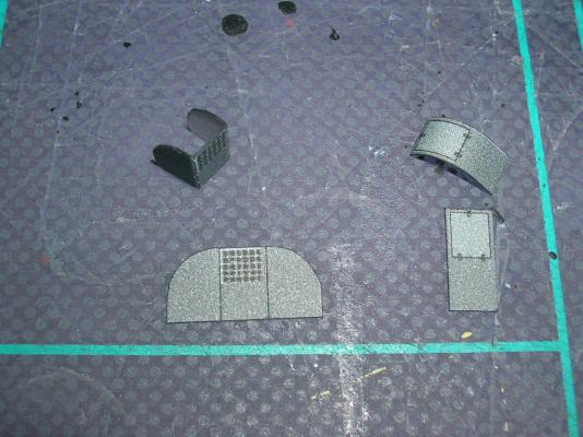
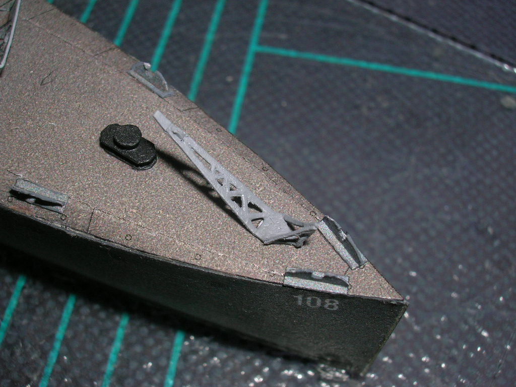
)The anchor crane (51) will require some very careful cutting.
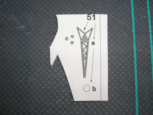
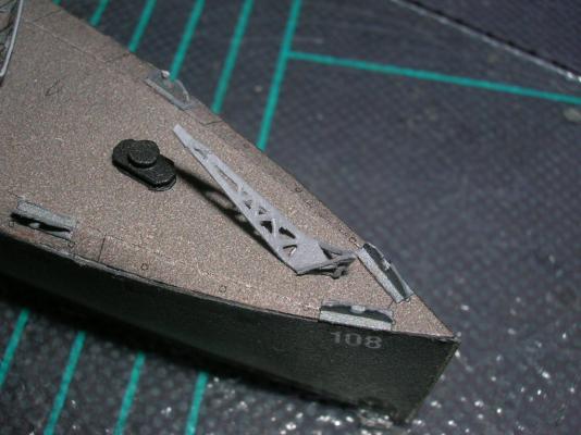
Start by removing all the interior white bits, using the push-cut technique we learned earlier. Before removing the crane from the parts sheet, stiffen the part by applying some CA to the back side. Parts 56c are a pulley; adding it to the crane requires making a tiny cut into the end of the boom and then inserting the pulley. Probably no one will notice if that's too much surgical detail for your liking and you omit the pulley. After cutting the crane out, folding up the back corners, and adding the base and pulley, I gave the whole thing a coat of gray spray paint before mounting it to the deck. You can try adding a cable if you so desire.
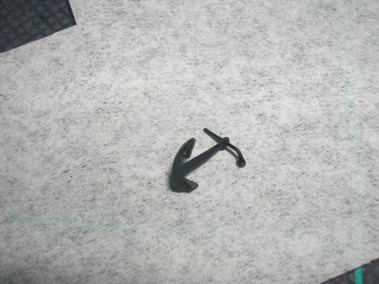
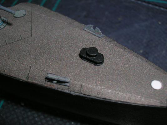
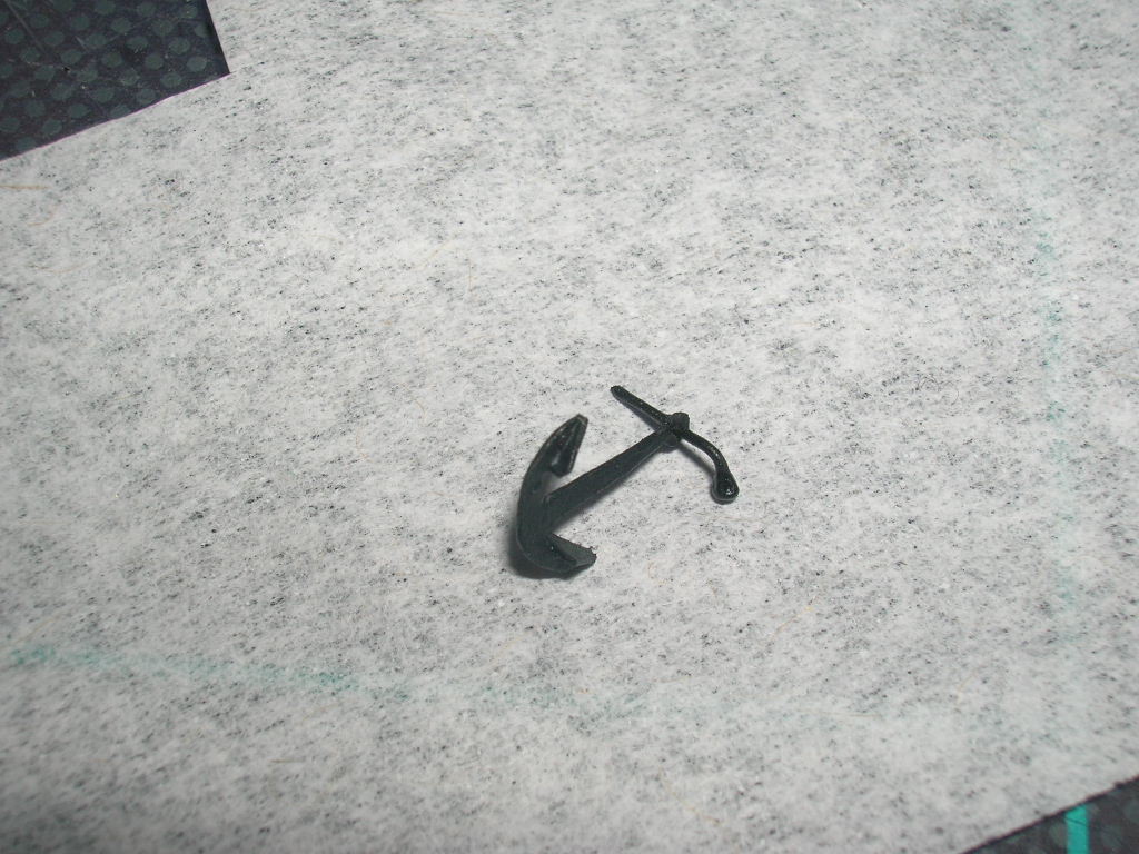
Next we'll make the anchors (56), but we won't mount them to the model until after the railings are added.
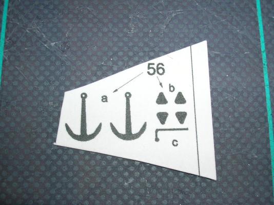
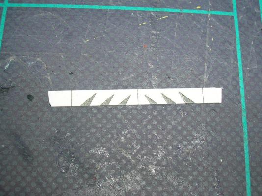
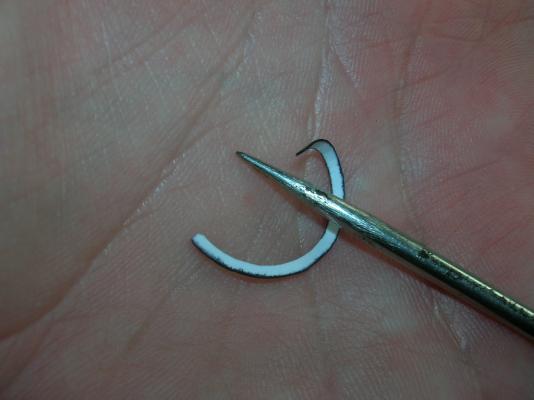
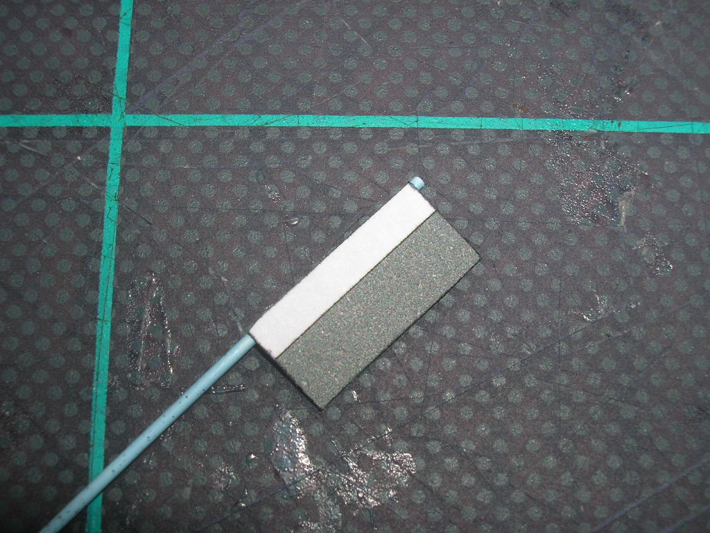
The anchors are another assembly I prefer to paint after constructing them. Punch the holes for the stocks before cutting the anchors (56a) from the parts sheet. Cut out and glue the flukes (56b) to the anchor arms. While those dry, you can use the template (56c) to cut two small pieces of wire to length for the stocks and add the bend. The knobbed end of the stock is easily made by dipping the wire into some PVA glue. The surface tension of the glue will pull it into the desired round shape. The glue shrinks as it dries, so you might need a second dunk.
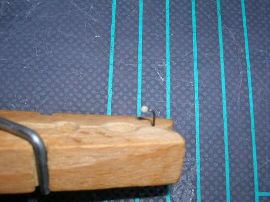
Add the finished stocks to the anchors and give both assemblies a coat of black paint.
Next I'll show you how to make something that will really add a sharp touch to your model: thread railings.
-
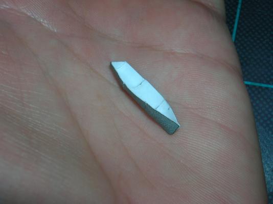
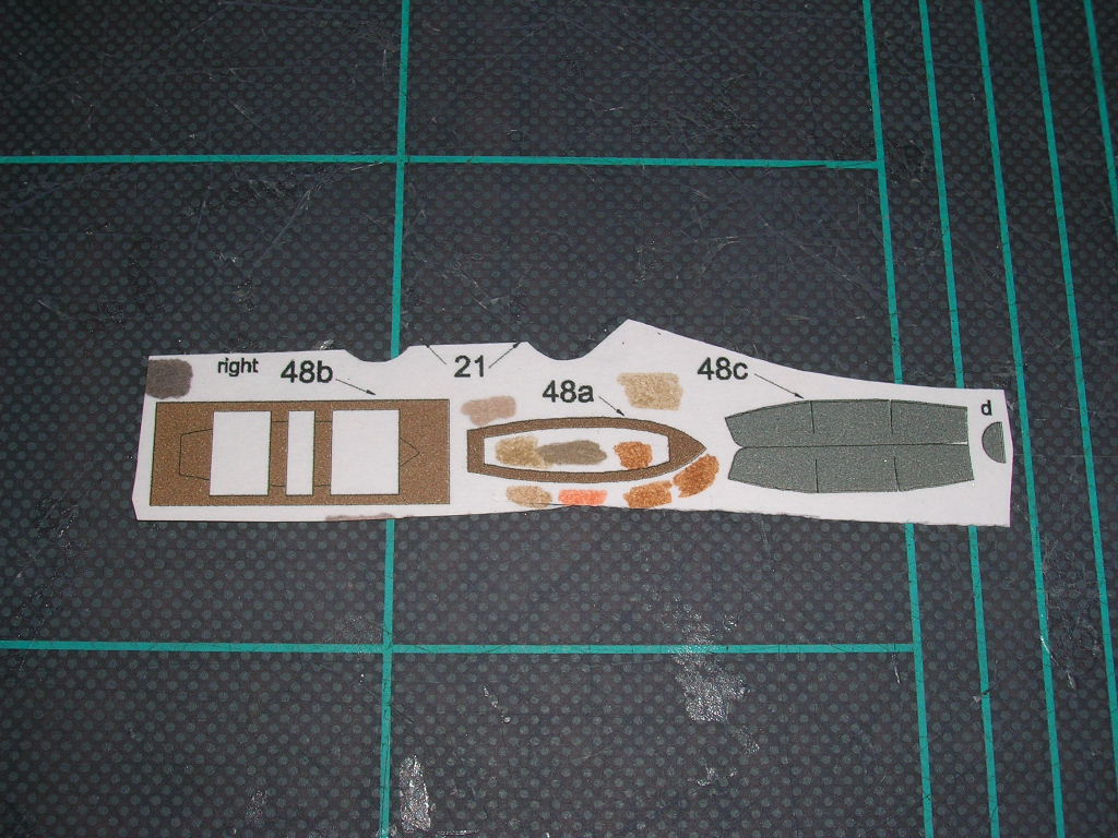
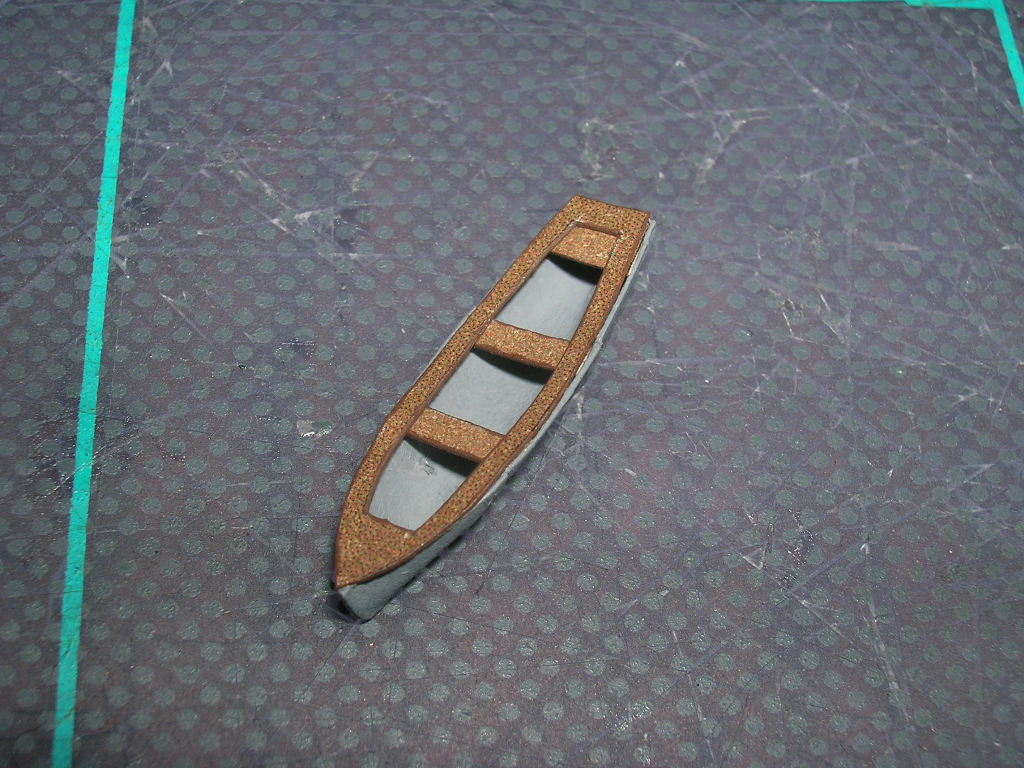
Ship's boat (48) is next.
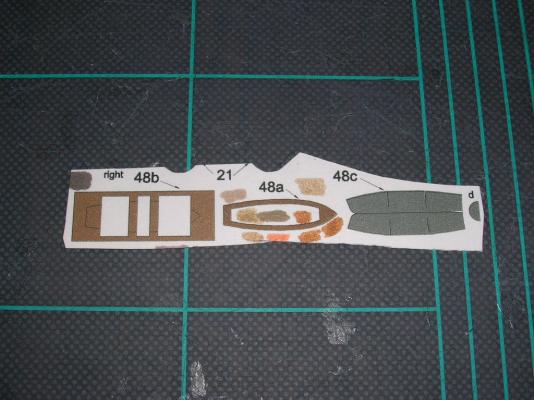
A paper ship's boat is mainly all about forming, forming, and more forming. I don't color the edges before hand, because whenever possible I like to paint the boats after making them. I use my scribing tool and the round end of a paintbrush to get the shape of the boat (48c) as close to the finished product as I can before I glue any of the seams.
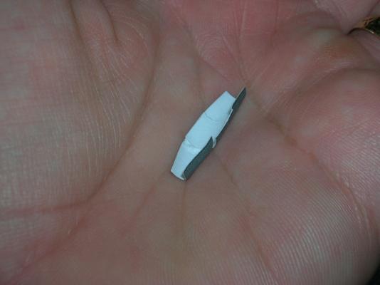
Next I seal the seam at the stem and add the transom (42d).
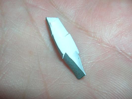
I glue the middle seams last. The boat now has its basic shape. It might need some additional forming to get it to match the outline of the caprail.
After the boat is painted, add the thwarts and caprail (42a and 42b).
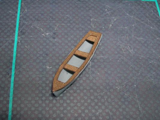
The kit doesn't include any boat chocks, but I can't imagine the ship wouldn't have had them. They're easily scratch-built from scrap card.
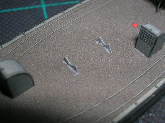
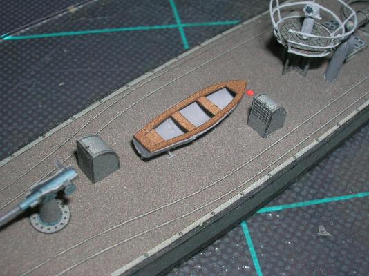
Mount the boat on the chocks (or to the deck if you opt for not adding the chocks).
-
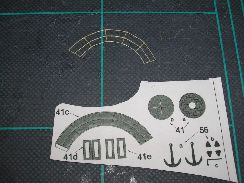
Next we'll add the rangefinder platform. At least, I think it's a rangefinder -- looks like one, and it's not a searchlight, so that's what we'll assume it is.
The platform (parts 41) does not present any new challenges...
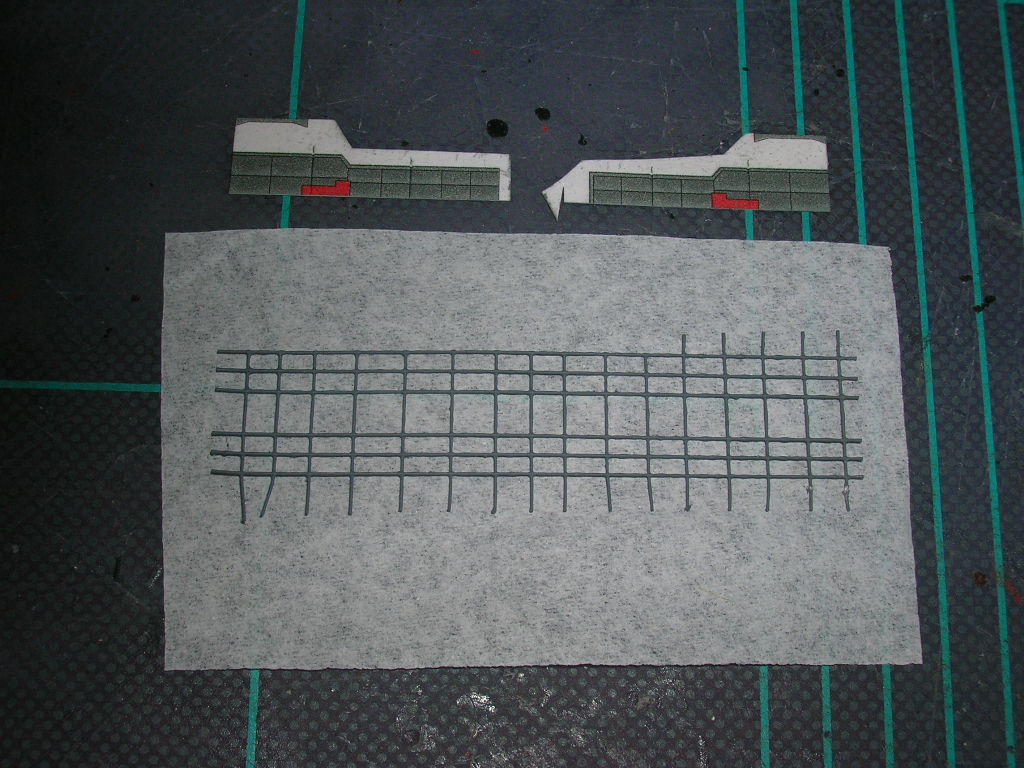
... unless you want to replace the printed railing (41c) with thread railing. I use quilting thread for making thread railings; it has a nice diameter and is far more fuzz-free than ordinary sewing thread. This particular railing will be more than the usual degree of difficulty, because the railing is actually part of a conic section. Use the printed railing as a template and cover it with wax paper. Stiffen the thread somewhat by running it through your fingers with a bit of PVA glue. While the thread still has some tack, you can stick it down onto the wax paper covered template. The wax paper will prevent the stick from being permanent. Start by laying down the curved railings and then glue on some short pieces of straight thread for the stanchions. Let this dry thoroughly before removing the railing from the wax paper. Paint the railing gray - spray gray primer works great. This PVA-glued railing will not be as stiff as the CA-stiffened railings we'll make later, so it can be formed into the necessary conic section shape before gluing it to the platform. I think it's a good idea to be consistent on how you mount your railings; I mount mine with the stanchions inboard. It's a minor detail, but one that might drive you to distraction if you later discover you have some stanchions inboard, but others outboard.
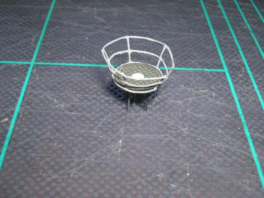
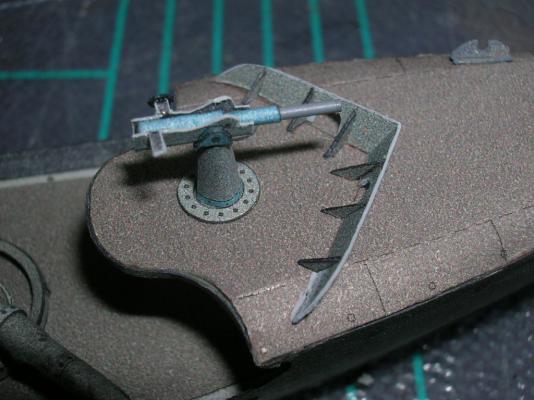
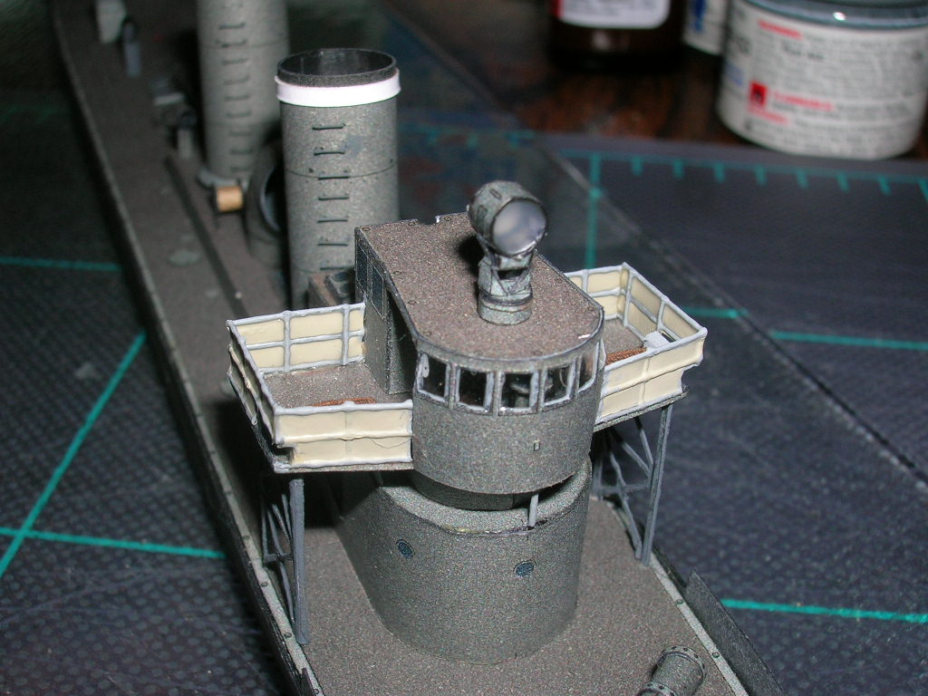
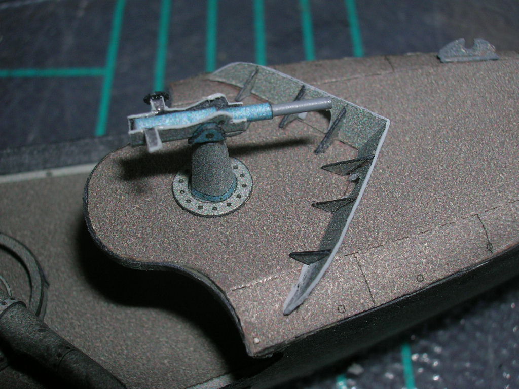
The finished platform looks like this:
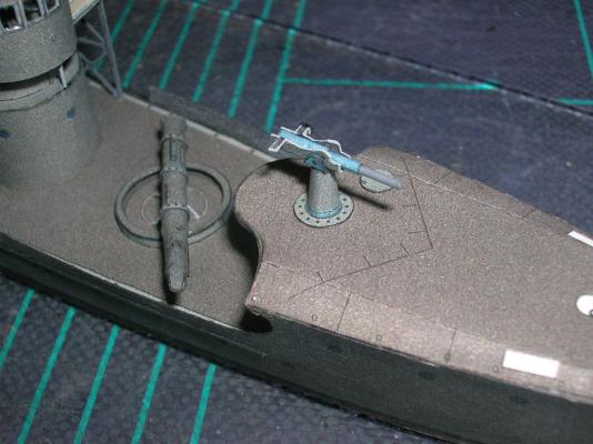
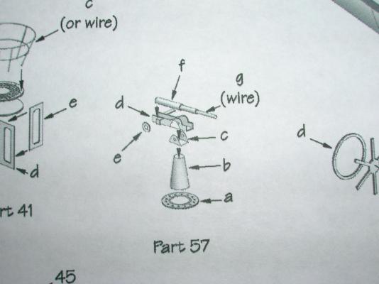
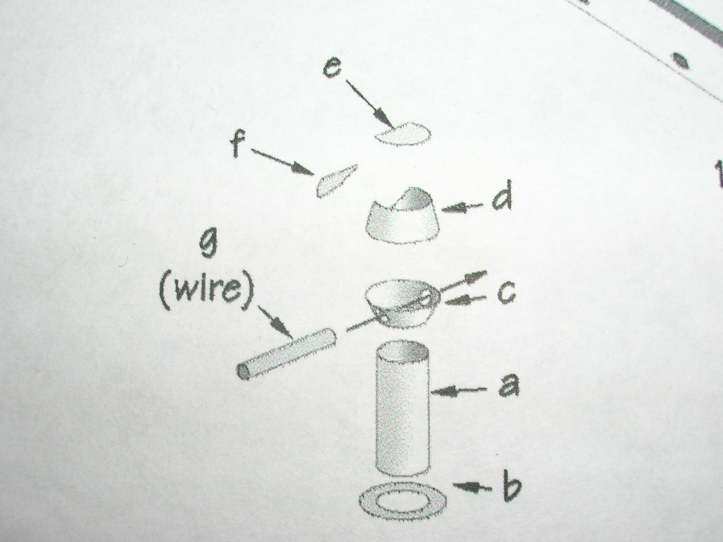
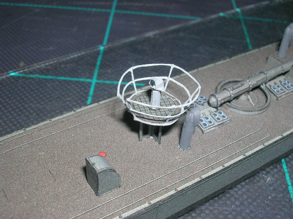
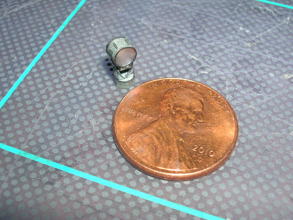
Now to the rangefinder itself.
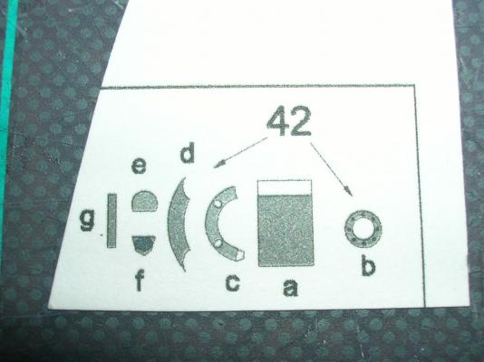
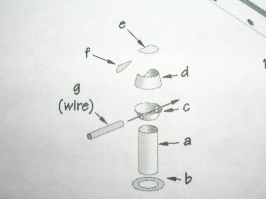
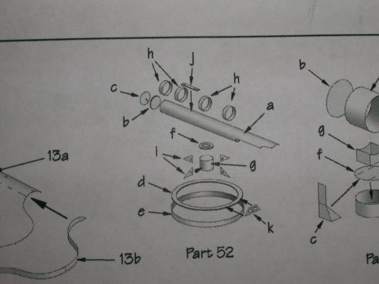
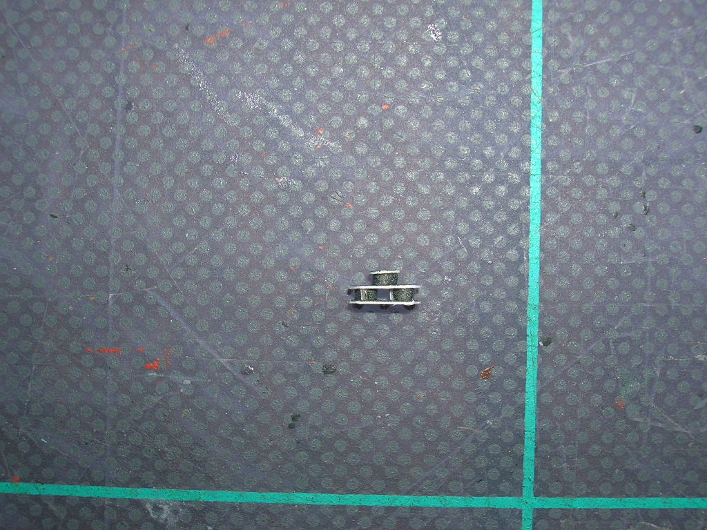
The post (42a and 42b) is no problem, but the rangefinder itself (42c-g) is an exercise in patience. The bottom of the rangefinder (42c) is a devilish part, no matter how you slice it. Start by removing the glue tab. Again, on these little parts, it's better to form the cone, add a little CA to the seam, and pinch the cone closed.

You can use the printed part 42g, in which case I would suggest cutting it into parts and gluing only the external portions. Or, you can replace 42g with a piece of wire, as I did. The wire needs to run through 42c, and because 42c is so narrow, if you punch the holes before rolling the part, the risk of tearing increases dramatically. If you punch the holes after rolling the part, you risk crushing 42c. It's six of one, a half-dozen of the other -- pick your method and work very carefully. I recommend adding parts 42d-f in that order.
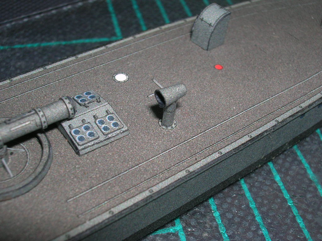
Here's the finished platform and rangefinder.

There should be a gap where the railing edges don't meet at the aft end of the platform. Likely there needs to be a ladder added from the deck to the platform at that point. The ladder can be made in a manner similar to the thread railings I'll show you a bit later.
-
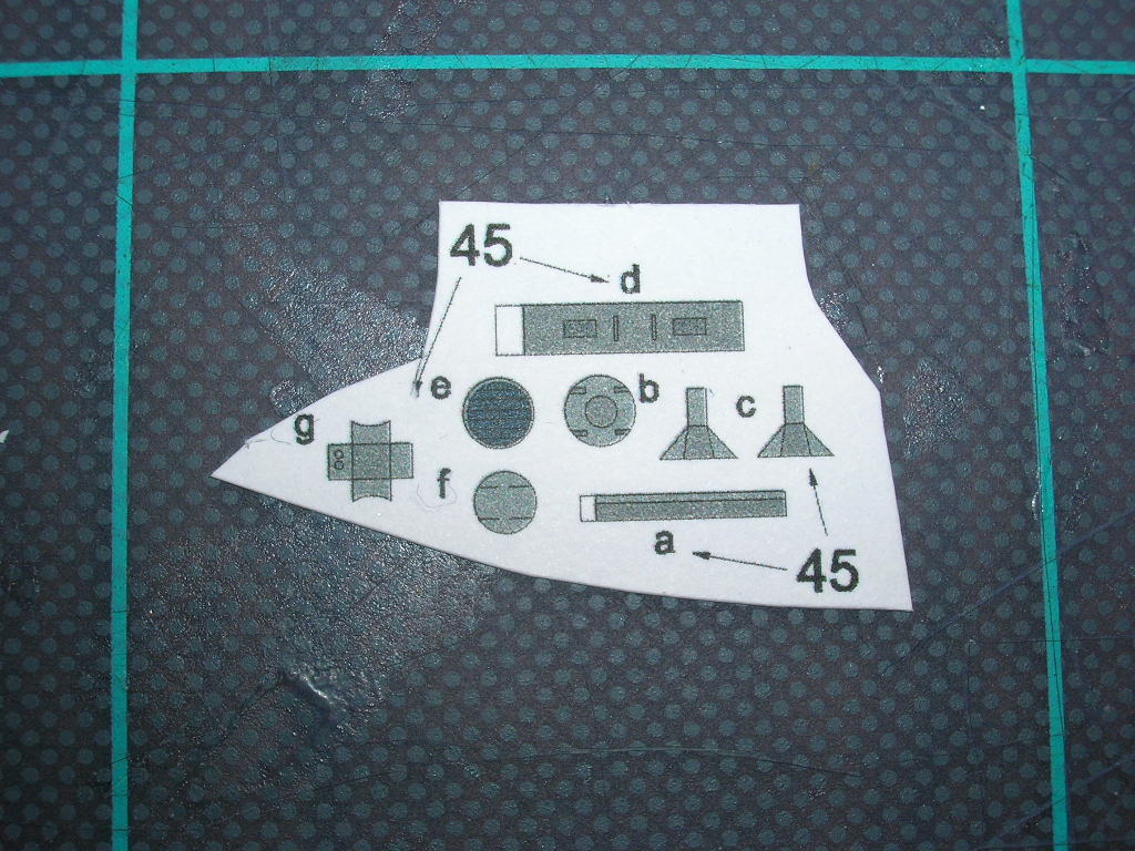
Next we'll add the searchlight (parts 45a-g).

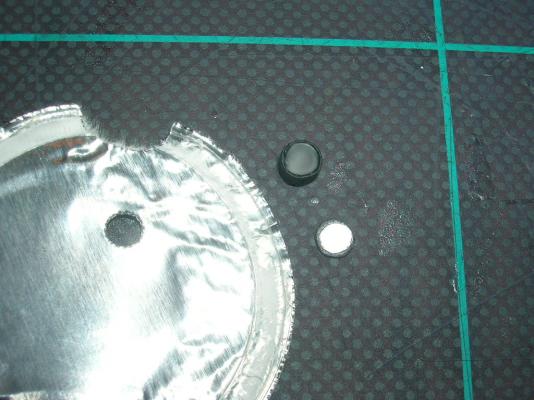
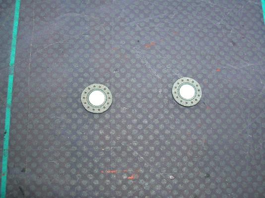
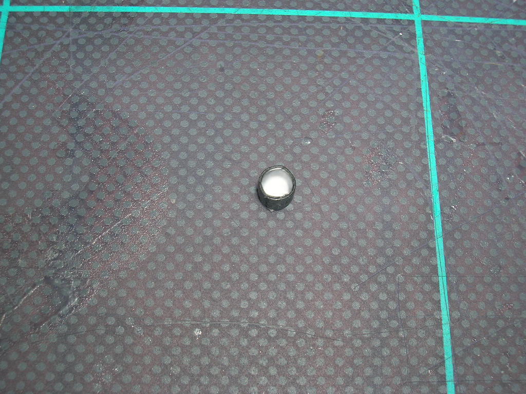
First, I'll show you how to replace the paper lens (45e) with an optional clear lens (key word: optional). Start by rolling 45 into a tube. Next, dab one end of the open tube into some white PVA, so that a film of glue covers the entire opening. Set that aside to dry. In the meantime, cut out the back of the lamp housing (45b). We'll use the resulting hole in the parts sheet as a guide for cutting out a small circle of reflective material for the inside of the housing. I used the foil-lined seal from a vitamin pill bottle - the foil is backed by paper, making it easy to glue the reflective liner to the back (interior) side of 45b. Make sure the liner is cut slightly smaller than 45b, because 45b will sit on the tube, but the liner must fit inside the tube. Here's the lamp housing with the optional clear lens, the foil-lined seal, and 45b with the foil liner cut to fit.
I didn't add louvers. If you want those, you're on your own.

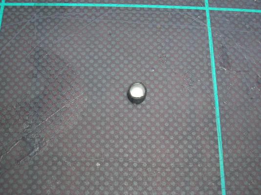
And here's the finished lamp housing. I know -- exciting shot, isn't it?
The searchlight mount (45a, c, f, and g) is a straightforward assembly, although once again it has some pretty small parts. Just work patiently and make sure you hold the parts over your work place. Up to this point I have dropped a couple of the smallest parts on the floor, and during the ensuing searches I found dirt particles on the floor that were larger than the parts.
Attach the lamp housing to the mount (the sides of the brackets, 45c, should reach slightly past the small box, 45e, and up onto the sides of the lamp housing), and then glue the mount to the top of the bridge.


Let there be light!
-
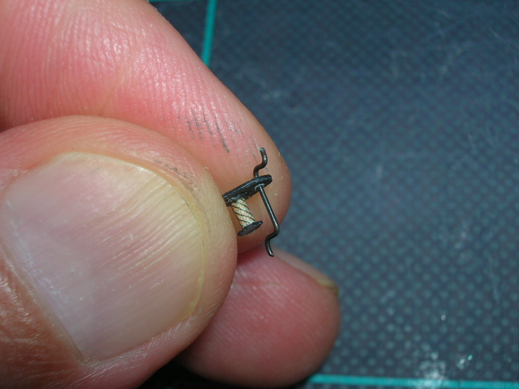
At the stern is a small hand winch.
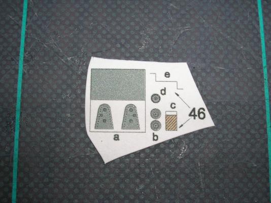
The two sides (46a) get doubled. After these parts are dry, cut out, and colored, glue the gear (46d) to the inside of one side panel, then use a small pin to make holes for the crank. There's a template on the parts sheet for forming the crank (46e), which should be made from very fine wire - which I happened to not have on hand anywhere, so I used some less-than-ideal larger gauge wire. Assemble the drum (46b and 46c); when that's done, attach the drum to one side of the winch. Don't attach the second side until after the crank is inserted.
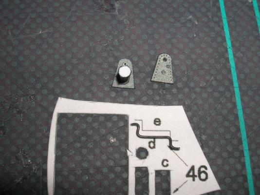
Thread the crank through one side, then the other, then glue the second side to the drum to complete the winch.

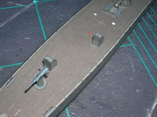
Glue the completed winch to the locator marks aft of the gun mount. The side with the extra gear goes to starboard.
-
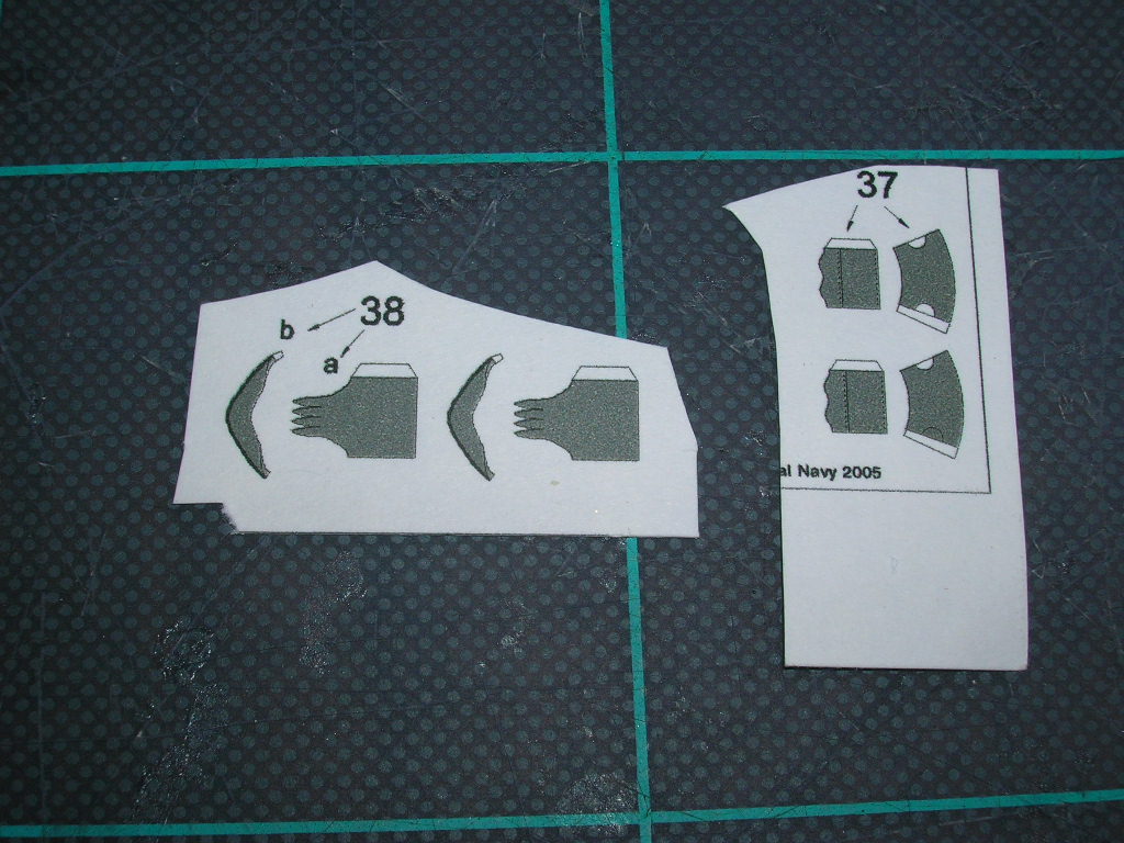
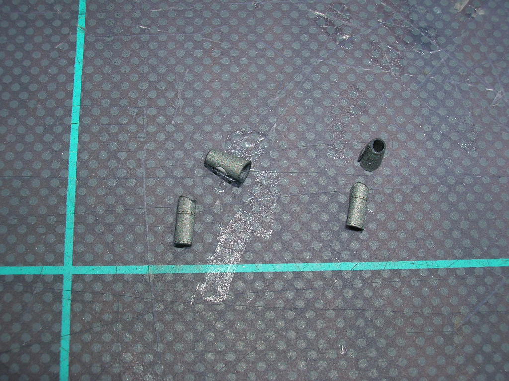
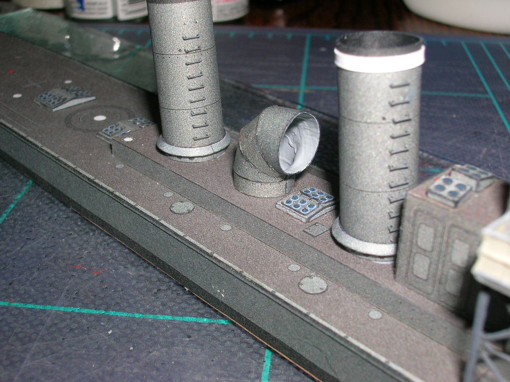
Next we have a series of small ventilators. One in each pair of ventilators is actually a venturi vent. Air passing through the tapered bore of the venturi created low pressure, which in turn drew air from inside the ship. Thus air flowed into a normal cowl ventilator, through the interior, and back out a venturi - a clever means of cooling in the days before air conditioning.
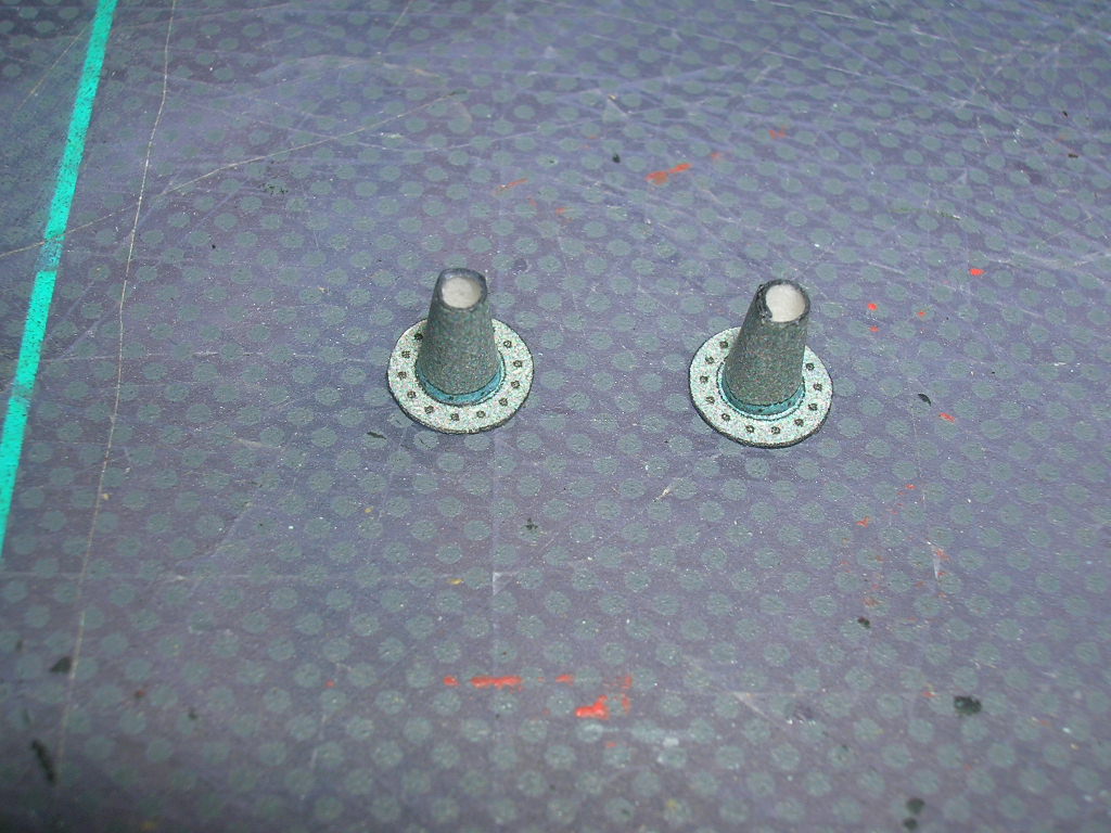
The venturis (37) are easier to build, so start with those.
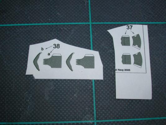
Each venturi is simply a conic section seated on top of a short tube.
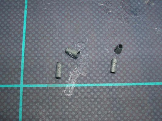
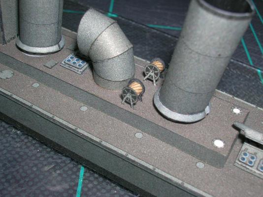
The forward venturi goes on the starboard side, while the aft venturi mounts on the port side.
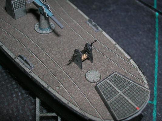
The cowl ventilators (38) introduce one of the banes of card modeling: petals (shudder!). Petals are one way of tackling curved tubes or rounded cones (the other is consecutive slices, as was done with the large ventilator between the stacks). The problem with petals is that they are, in my esteemed opinion, one of the most difficult card structures to form and glue properly. Fortunately, the number and size of petals in this instance is small; any flaws in their construction will have a minimal visual impact.
Start by rolling the tube (38a) for each ventilator.
Then, gently bend over each petal. You'll see that the petal tips will want to come together at a point. Brush some white PVA onto the petals, being sure to get some into the seams. Gently form the petals together with your fingers while the glue sets.
The cowl is made by gluing 38b into an oval to match the opening of 38a. Glue the cowl to the tube, then work the seams, either with your fingers or a blunt tool, to get them sealed as well as possible. I find it best with small cowls like these to paint the entire finished cowl. Mount the cowls to the opposite side of their venturi partners.
Now, pat yourself on the back for having finished your first card petals!
-
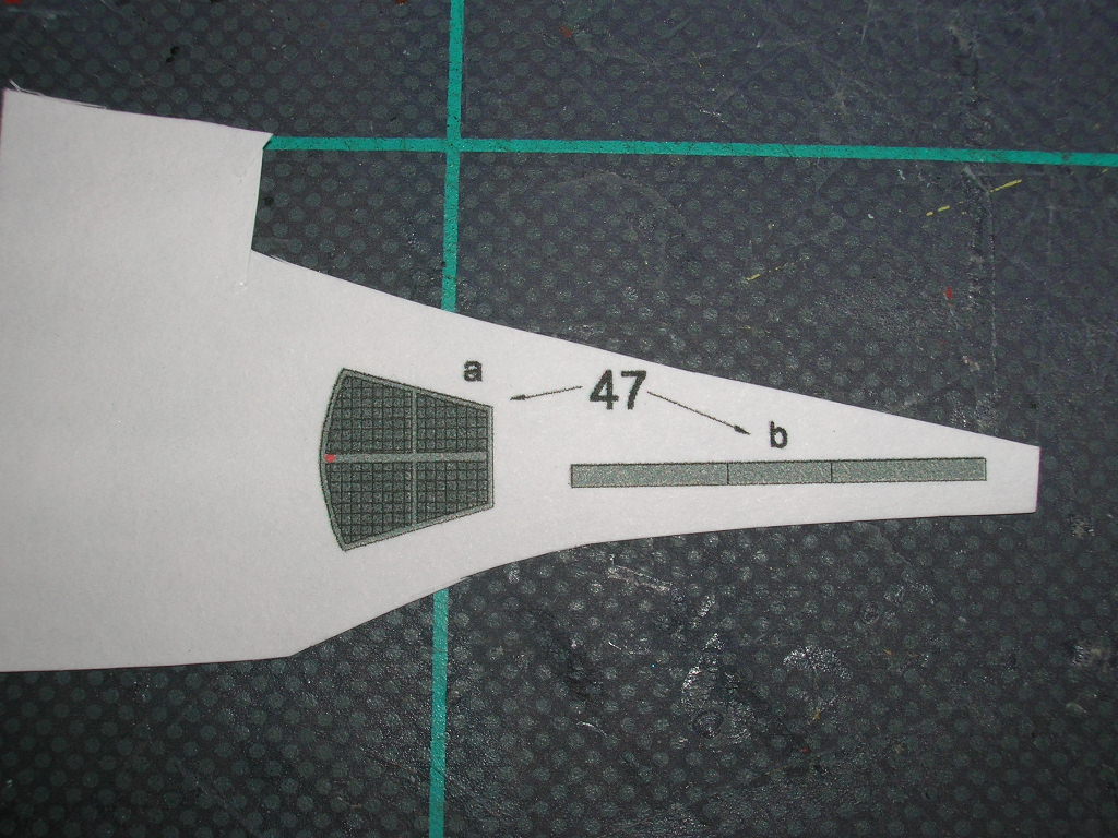
Now we'll head to the stern, starting with the grating (part 47) that covers the steering gear.

You'll need to paint the visible portion of the deck beneath this part before gluing it down. Apply the edging (47b) to the grating (47a). Note that the aft edge of 47a gets no edging - that's where the tiller would pass through to the rudder. A few bits of locator strips are helpful in getting this part positioned correctly.
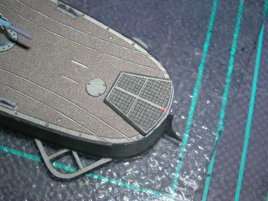
I have no idea what parts 43 are - some kind of vents, or perhaps companionways. Anyways, these are also fairly easily constructed. Just remember to round the back (43a) part before gluing it to 43b.
Attach the finished assemblies to the aft deck.
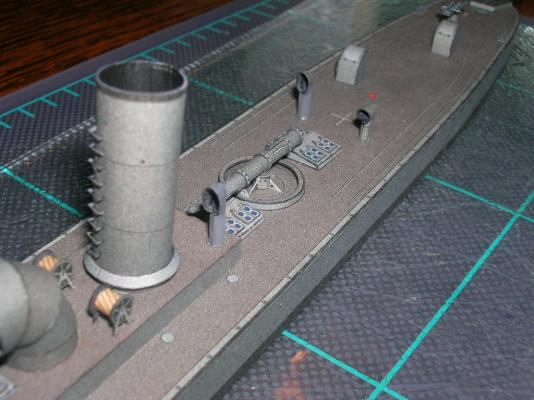
Between the aft stack and the large funnel are locator marks for a pair of hose reels, parts 53.
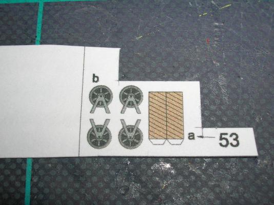
It's a good idea when gluing the hose drum (53a) between the end plates (53b) to glue it so that the seam is on the bottom and out of sight. Other than that, the only tricky part about the reels is being very careful with the delicate legs. Be sure when you glue the two end panels to the drum that they are aligned properly, so that the reels will sit level on the superstructure.
-
At this point, most of the major structures are completed. It's down now to finishing off miscellaneous small bits scattered around the ship. I have some personal, general guidelines I follow (not necessarily to the letter) when I add these parts: 1) Work from the center superstructure towards either end, and 2) add shorter structures first, since tall structures are easily knocked off when working around them on the model. This means the parts numbering sequence is out the window. Of course, it has been for a while now, hasn't it?
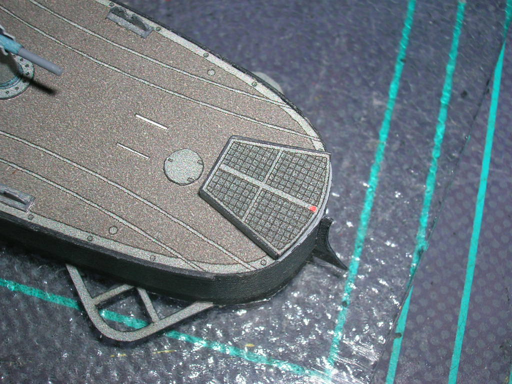
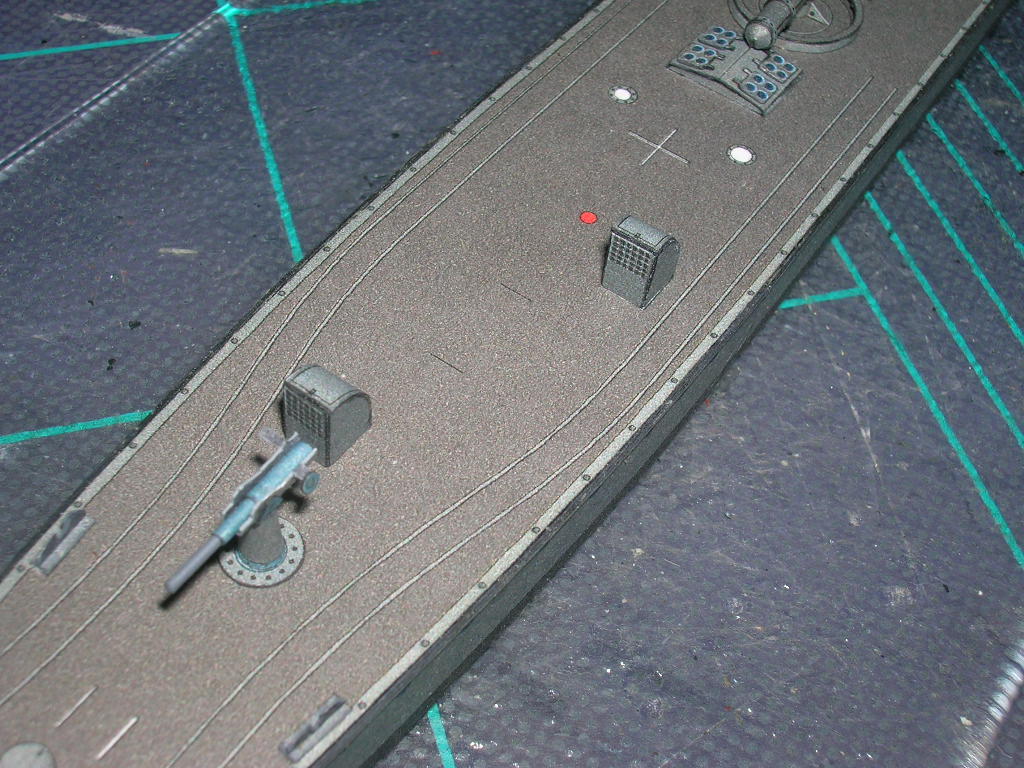
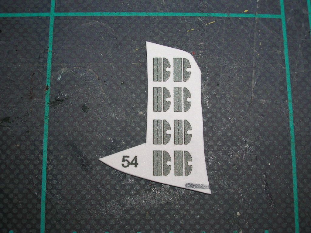
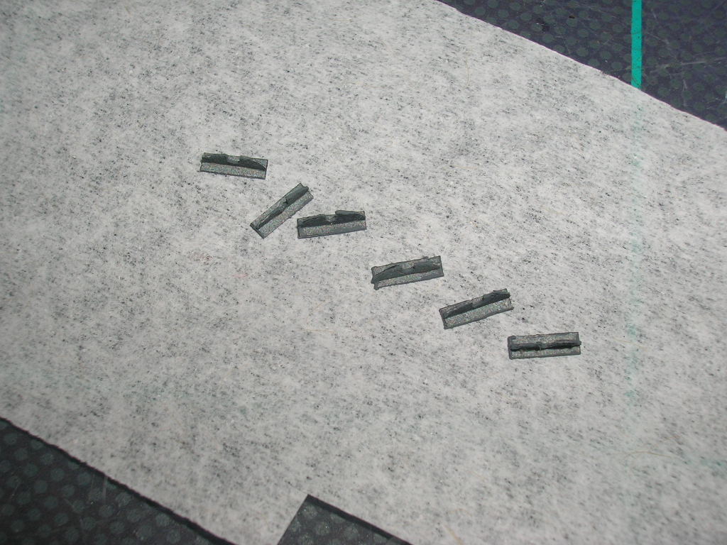
We'll start at the forecastle. Parts 54 are chocks.
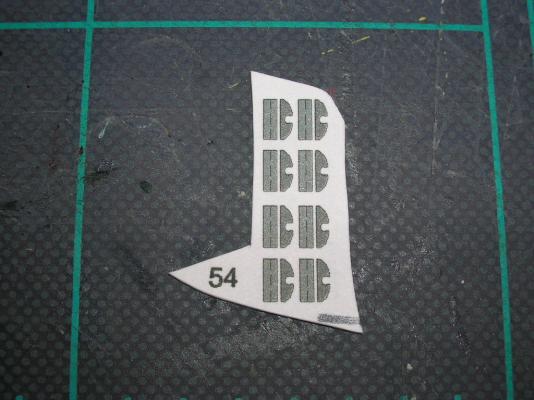
These are easily built, though tedious to cut out, as are many of the parts to follow. Color the back side of the chocks before cutting them out. The horns are glued on the lines running down the middle of the base plates.

There are parts for eight chocks, but only six are needed, four on the forecastle and two at the stern.
There's also a two-tiered capstan on the forecastle, part 50.
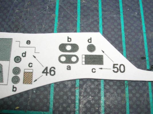
Don't bother edge coloring the tiny bits for this assembly - just paint the entire part black once it's finished. Part 50c gets cut into three strips. Each strip gets glued into a ring. The parts are then glued into a stack - two parts 50c onto 50a, capped by 50b and topped with another 50c plus 50d. Looks like this:
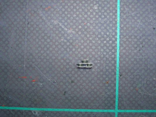
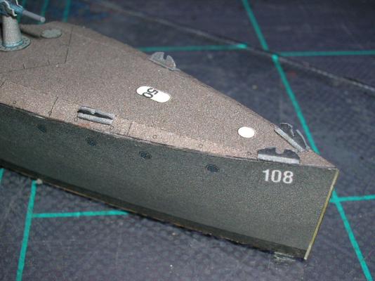
After painting the capstan, glue it down to its spot on the forecastle deck.
Finally, there's a breakwater (49a) to add. It glues down to the angled line that crosses the forecastle deck in front of the gun mount. 49b are the braces that go aft of the breakwater. The larger braces are inboard and get progressively smaller as you work outboard. To prevent these tiny parts from getting lost, cut the braces from their doubled parts sheet only as needed.
The finished breakwater looks like so:
We'll add the anchor hoist later due to its delicate nature.
Return to Part VII: Building V108 - Armament
-
The real La Recouvrance is a beautiful ship. Good luck with your project!
-
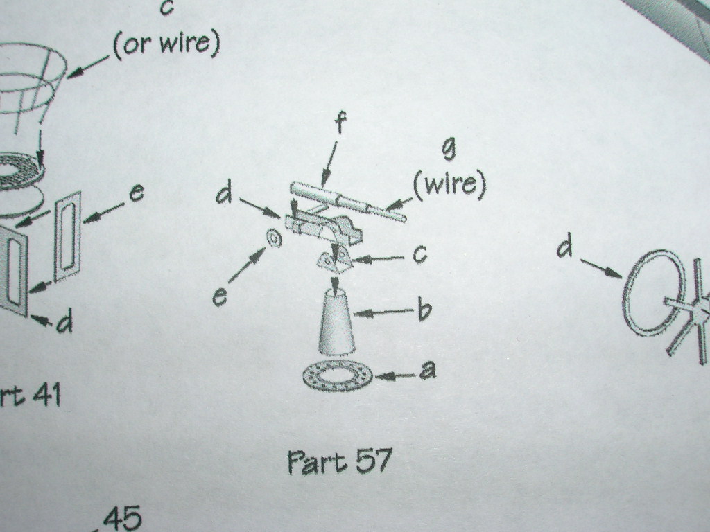
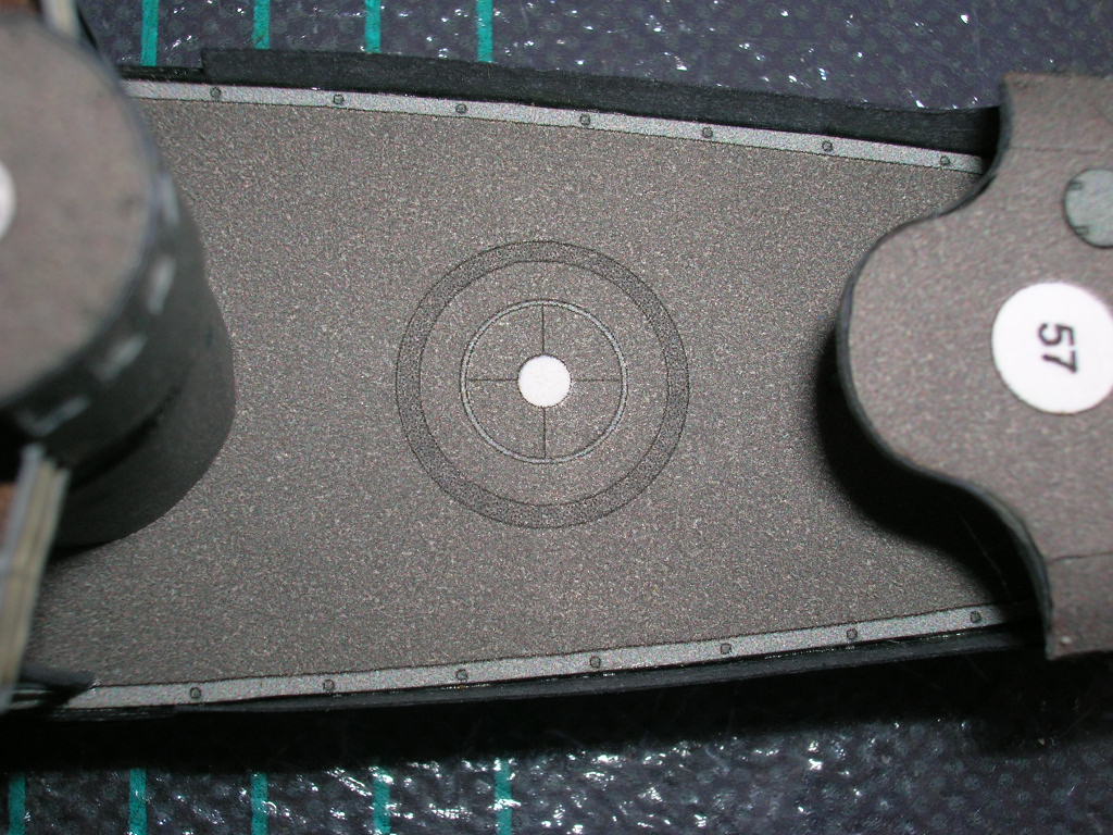
Building the guns is straightforward, albeit another exercise in handling tiny parts. Start with the mount base plates (57a).
The stand (57b) is another conic section. Glue the finished cones to the base plates. Set these aside for now.

The carriage consists of three parts, the carriage slide (57d), a wheel (57e) (Traverse? Elevation? Your guess is as good as mine.), and a mounting bracket (57c).
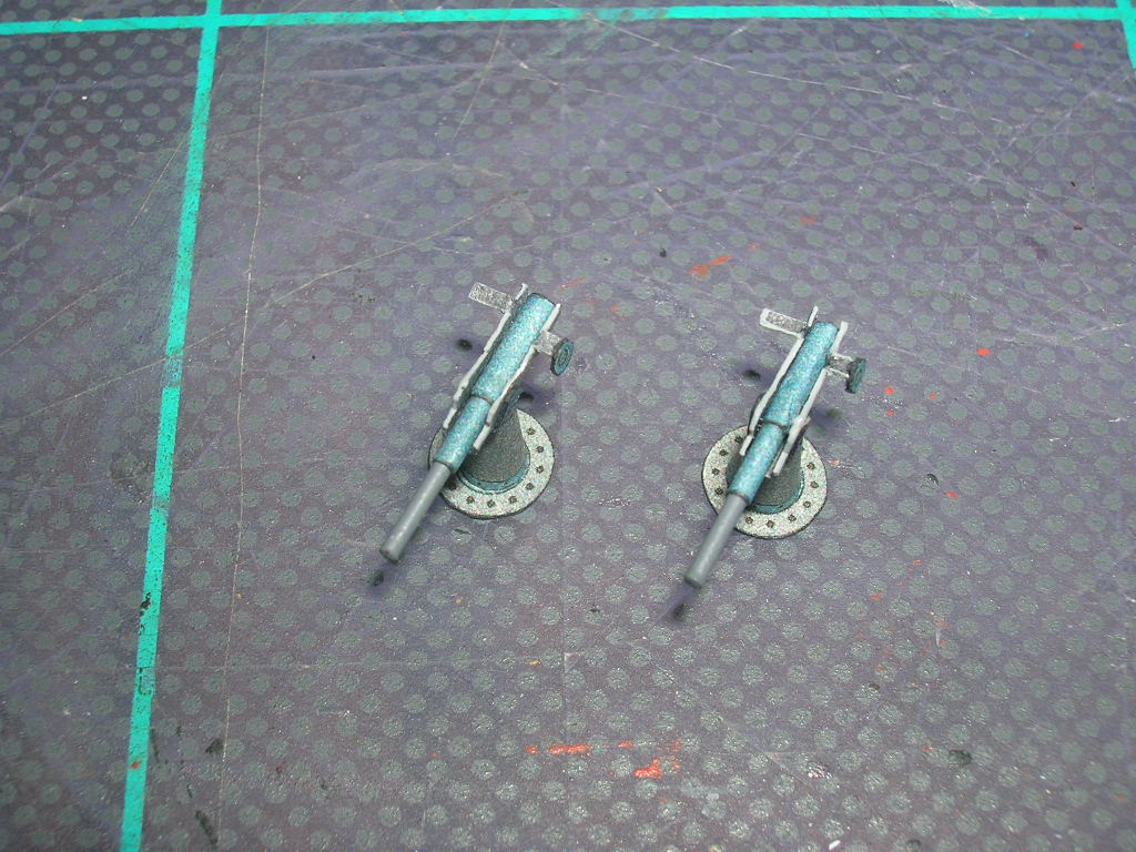
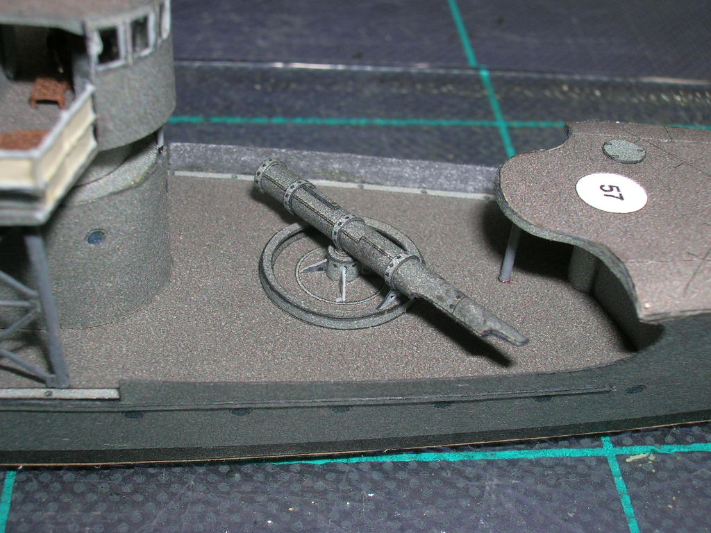
Fold up the carriage slides carefully, then attach the barrels, wheels, and brackets.
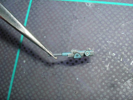
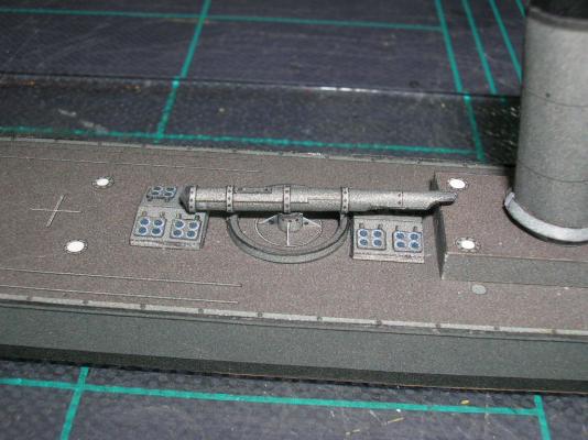
Glue the guns to the mounts...
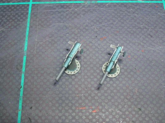
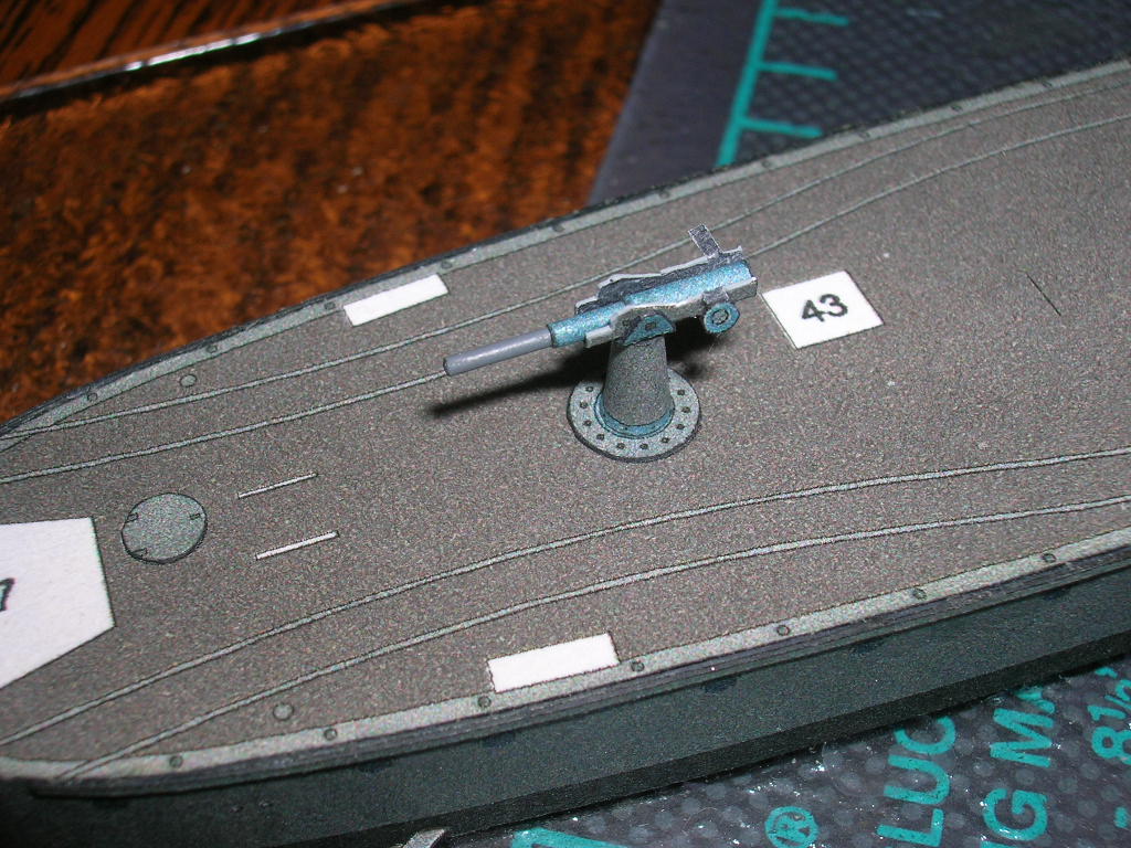
...and the mounts to the aft deck and forecastle.
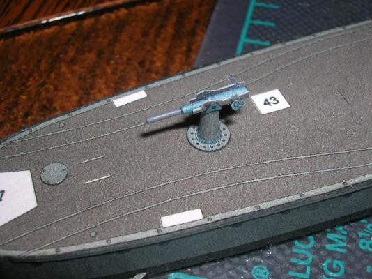
Now you're done with the armament!
Go to Part VIII: Building V108 - Miscellaneous Bits
-
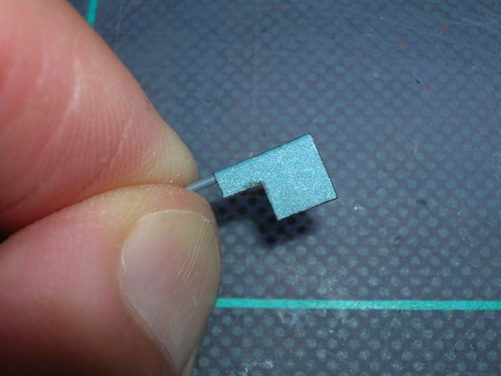
A pair of deck guns will complete V108's armament. From what I can find on-line, these were likely 8.8 cm guns. Whatever their caliber, one thing you can be certain of is that the kit guns are highly simplified; it is simply impossible, in this scale, to replicate all the parts of even a simple gun mount in paper. There's lots of possibilities here for the super-detailers among us, but for the purposes of this tutorial, we'll build the guns as-designed.
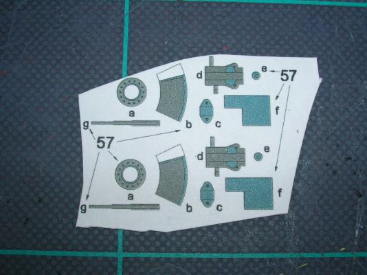
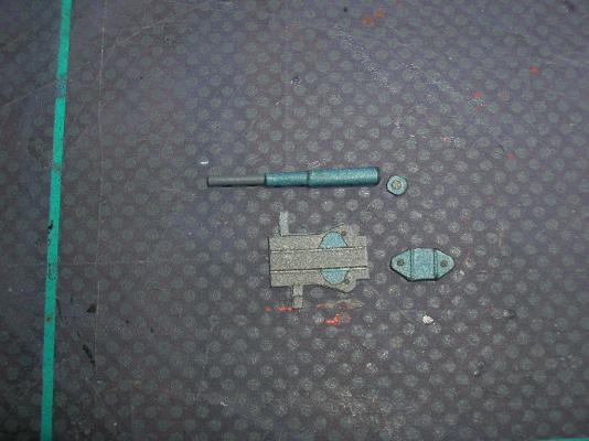
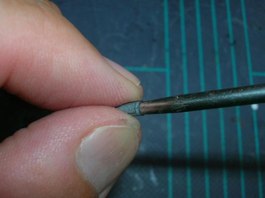
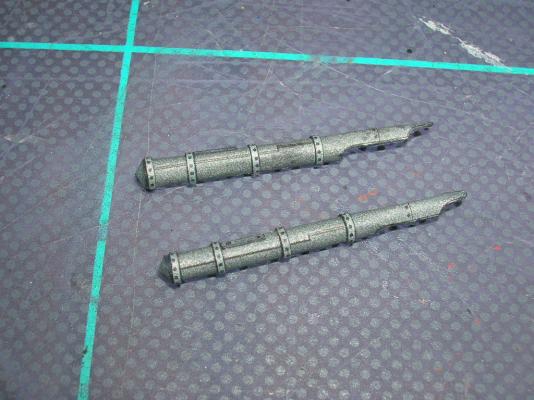
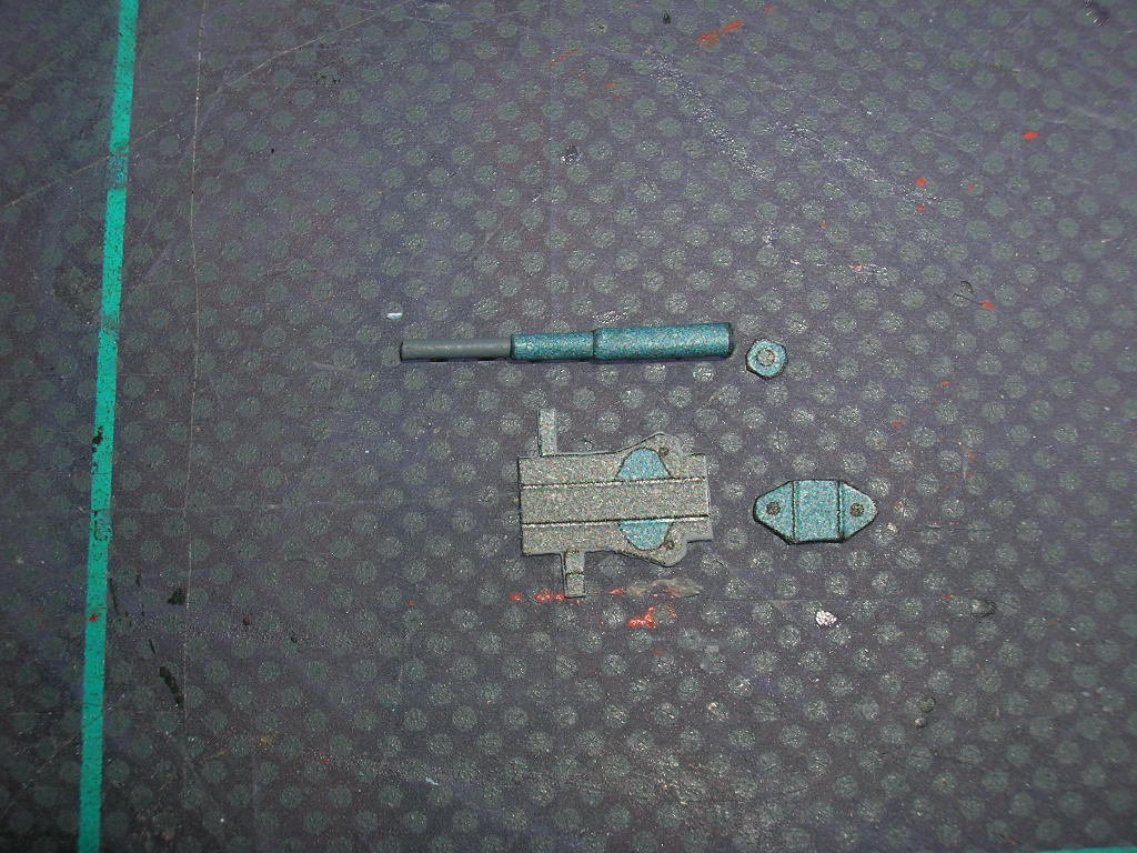
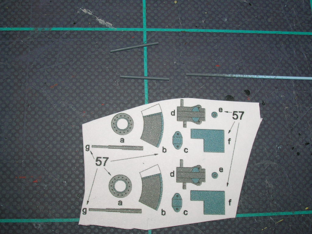
The gun parts are numbers 57a-57g. Part 57g, the barrel, can actually be used in its paper form, but it should really be replaced with wire or styrene rod. I prefer styrene rod simply because it cuts cleaner than wire and doesn't require grinding to get a flat face at each end. The rod is sprayed gray prior to cutting, and 57g is used as a template for the length.
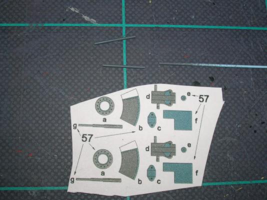
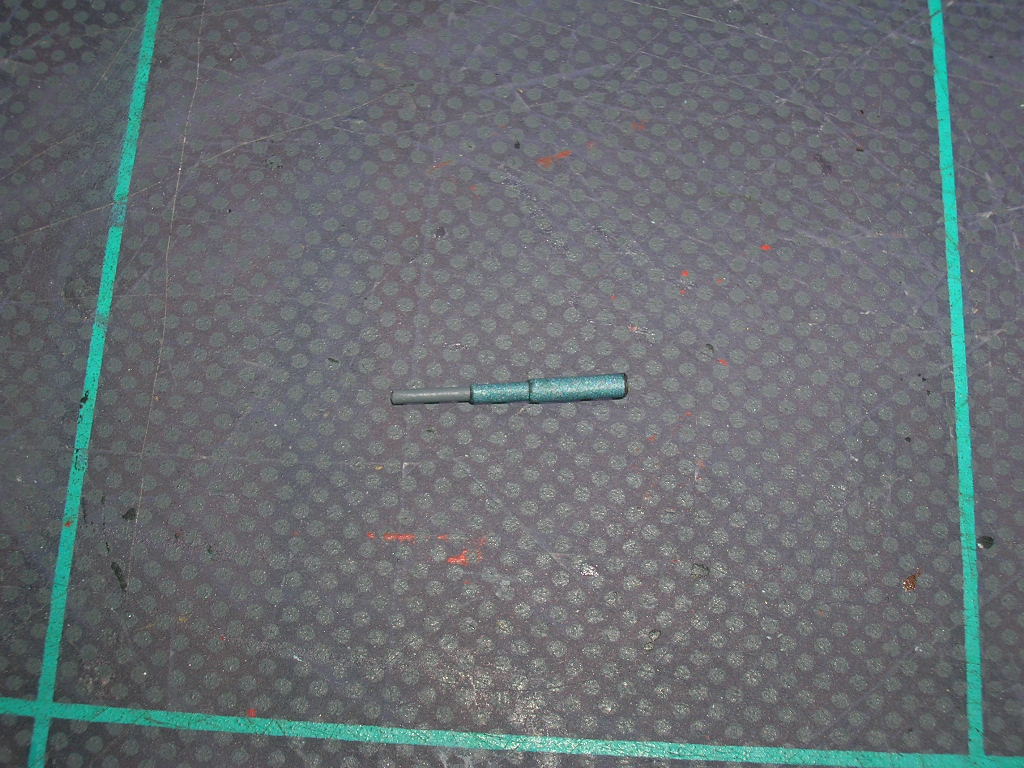
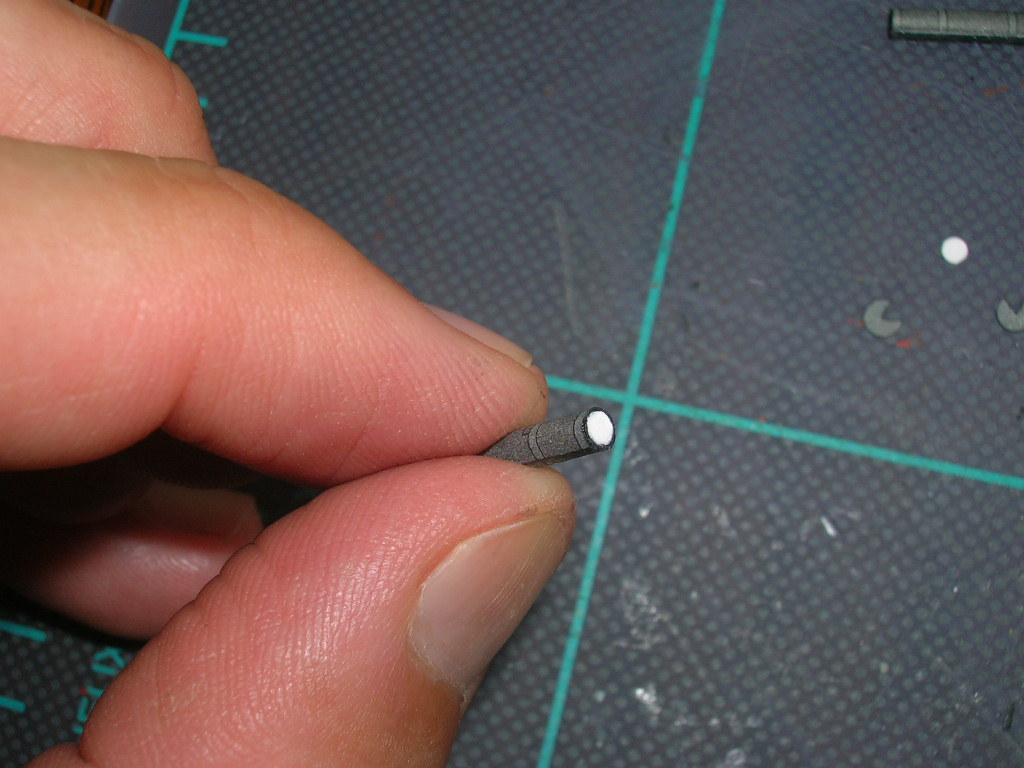
57f is a wrapper that will produce the stepped-down taper of the barrel. Use the 20# bond version of this part. Start by tacking the wide side of 57f to the end of a barrel.

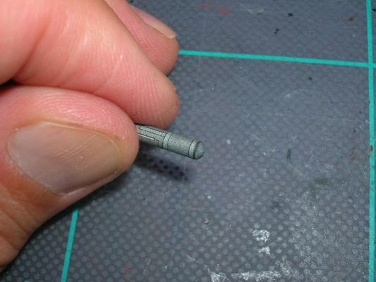
When that's dry, coat the remainder of 57f lightly with glue and wrap it around the barrel. Finished barrels look like this:
-
-
On to the tubes!
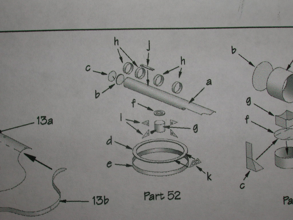
The torpedo tubes (52a) need to be rolled into tubes. They also need to be colored on the reverse side. On narrow tubes, it helps to roll the tube around a series of forming tools of increasingly smaller diameters. It also helps on this particular part to remove about half the joiner tab. Sometimes, in spite of one's efforts not to squish the tube, it gets a little squished anyways. My scribing tool works well in such instances for rounding the deformed tube end.
A tiny former (52b) gets inserted into the breech end of the tube. Cut inside the line to ensure the former will fit.
Next comes the conical breech door (52c). The joiner tab on this part is actually more trouble than it's worth, so remove it. Form the door until the edges will meet, then seal the seam with a bead of CA. Add the door to the breech end of the tube.
A series of four reinforcing bands (52h) are then added. Don't try to make these into rings first - there's a much easier way. Remove the joiner tabs from the rings. Tack one end of the band to the launcher tube at the tube's seam.
When that's dry, brush a small amount of glue to the remaining band, then roll the band onto the tube. Add part 52j between the second and third rings. The finished tube looks like this:
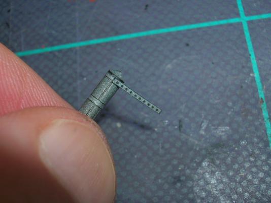
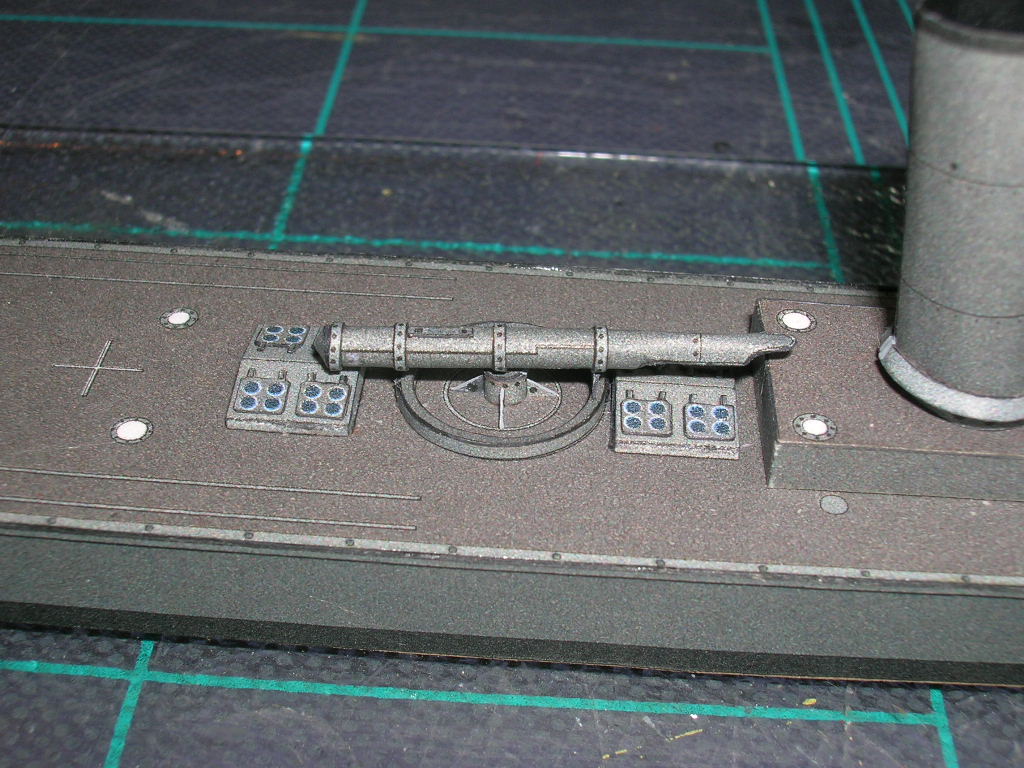
Gluing the finished tube to the pedestal is easier if the tube is pinned. Drill a small hole in the pedestal and tube; glue a short piece of wire into the tube. While that dries, you can work on the track support brackets (52k). Carefully remove the tiny panels from within the brackets, then color the insides and reverse sides of the brackets. Next, cut out the brackets and color the edges.
You'll need to decide which direction you want your tubes aimed prior to gluing down the support brackets; the forward tube cannot point directly forward because the forecastle support column is in the way. I mounted the aft launcher fore-and-aft, and the forward launcher is aimed slightly to starboard. The finished launchers look so:

V108 now has some teeth!
-
The first armament to be installed will be the torpedo launchers, two seemingly complex and fiddly structures consisting of 16 parts each.
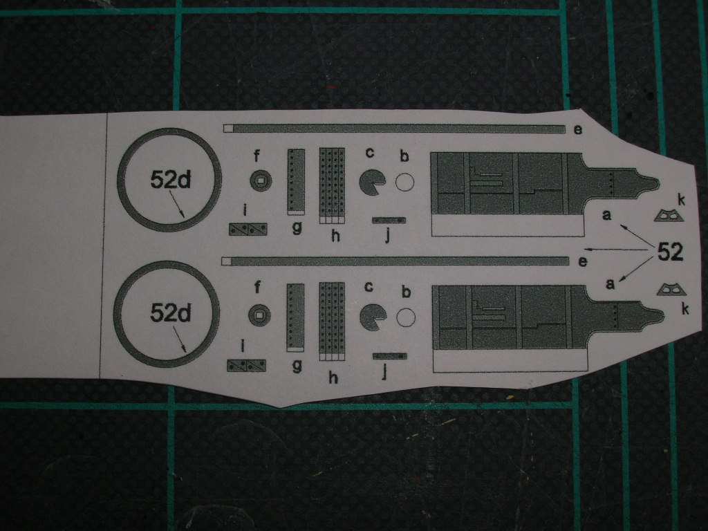
The parts for these are conveniently located together on the parts sheet. Believe it or not, I have built models where this wasn't the case - go figure.
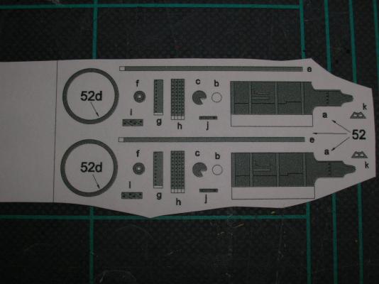
There are two launchers on the model, one forward of the bridge, and the other aft of the superstructure. The launchers are identical, and on assemblies like this I prefer to build them simultaneously instead of first one, then the other.
This is another construction sequence where it makes more sense to me to assemble the parts out of sequence. We'll start with the pedestal. Cut, color, roll, and glue the pedestals (52g), then add the caps (52f). Glue these down to the deck. Next, add the triangular support brackets (52i); these are tiny right triangles, and the long leg of the triangle goes on the deck. The finished pedestals look like this:

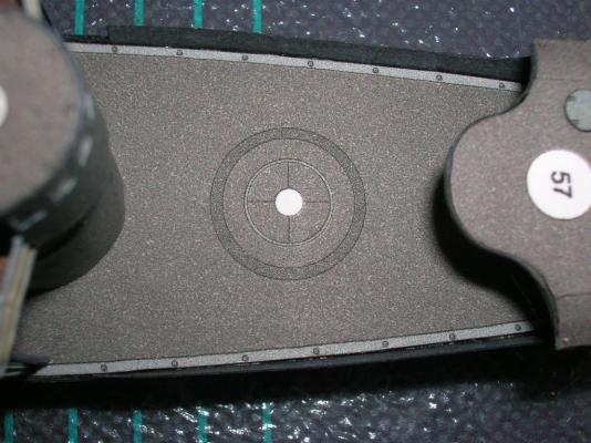
Next comes the ring-shaped structure that I'm presuming is a kind of track that the tube support brackets (52k) travel around when the tube is aimed. This consists of two parts, the ring (52e) and the circular track (52d)(the upper parts in the picture below). The inside of 52e needs to be colored, because it will be visible on the finished launcher.
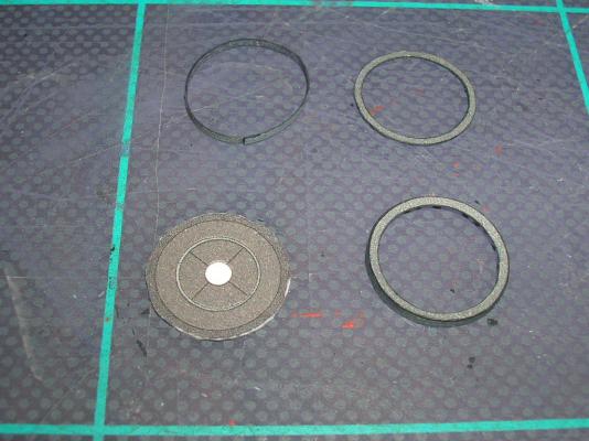
The ring, when closed, will be rather flimsy, and mating the track to it will be difficult. To fix this, we're going to use the spare deck printed on 20# bond. Remove two small squares containing the launcher locations from the spare deck, then laminate these to a couple of sheets of card. When dry, cut out the circular mount location, being careful to cut inside the line. Presto! Now you have a circular former to help you get the ring (52e) nice and round before adding the track (52d) (the temporary former is in the lower left of the previous photo). Work the ring carefully around the former and be sure it is seated at the bottom of the ring - we don't want to accidentally glue these two parts together. Next, cut out and add the track (52d); remember to remove the inner circle first, color the inner edge while the part is still on the sheet, then cut the outer circle. After the ring and track are glued together, the temporary former can be removed. The finished ring/track is in the lower right of the previous photo.
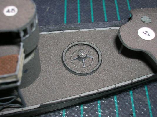
Here's the forward ring glued down to the deck.
Return to Part VI: The Superstructure
-
One of the most difficult parts of a card model ship to build convincingly, if you can believe it, is ventilators. Designers use different techniques for constructing them, and they are all equally a pain. I still consider myself a novice at building ventilators.
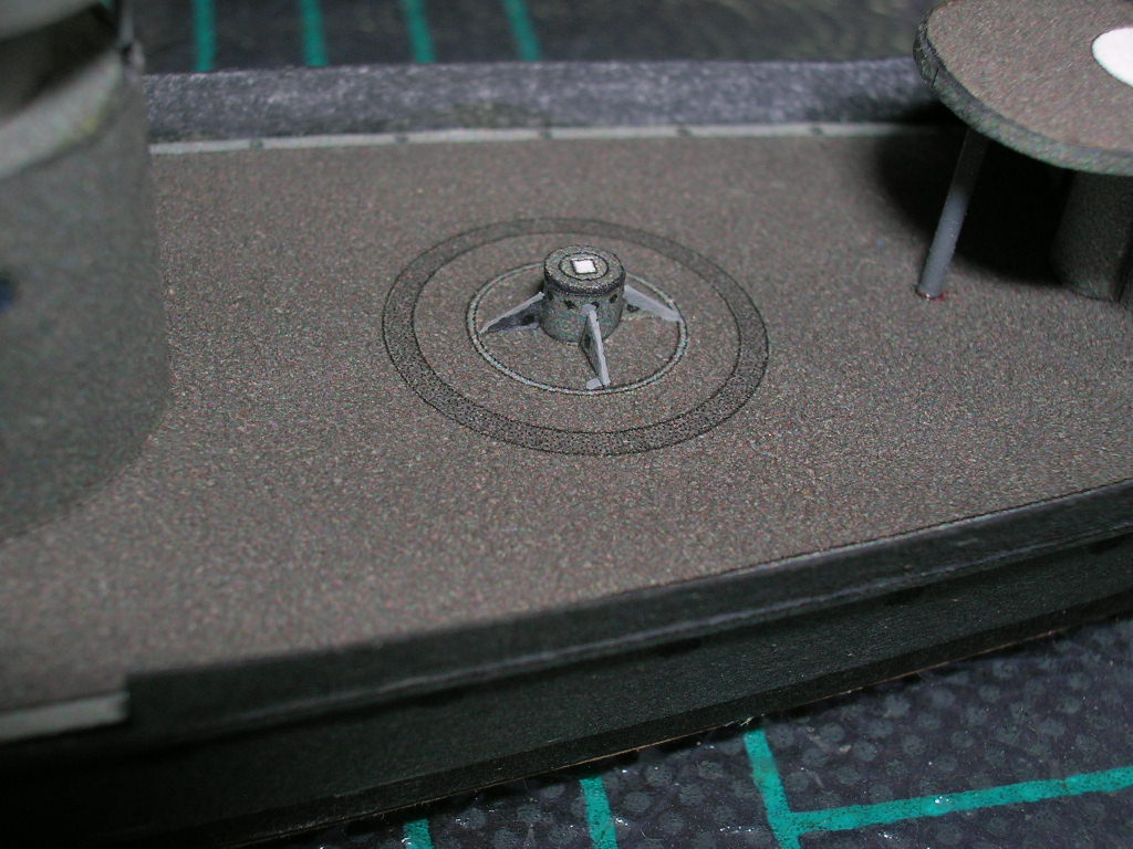
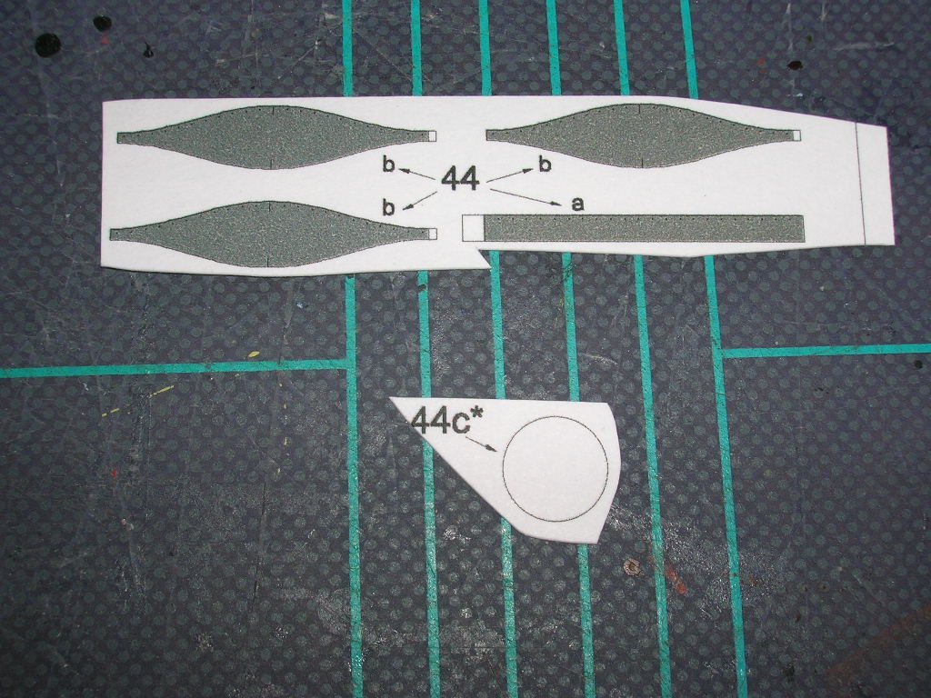
Parts 44a-44c make up the boiler room ventilator. This particular ventilator is made by gluing up a series of rings and then putting them together to make the curved tube.
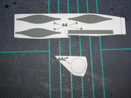
Part 44c should have been one of the parts laminated onto 1 mm card stock, but I somehow overlooked it. No problem - I simply backed the part with two layers of plain card, and as I said much earlier, this type of built-up part is actually easier to cut out.
Parts 44a and 44b need to be cut out, colored, rolled into rings, and glued closed using the small glue tabs. I cannot stress enough how important it is to cut these parts as precisely as possible - the fit between adjacent rings totally depends on how accurately the parts are cut, and even very small errors will result in unsightly gaps in the seams. Same goes for gluing the rings shut - make sure the overlapping end of each ring hits the edge of the glue tab dead-on, or you'll wind up with rings of different diameters.
44a wraps around the base, 44c. An easy way to do this, once you have the 44a ring closed, is to lightly coat the inside of the ring with glue, set it flat on your cutting mat, and then press the base former down into the ring while holding the ring down with your fingers. The flat mat will ensure that the ring and base match up flush.
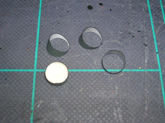
Step one of getting the ring segments mated is to make sure they are as truly round as possible; lopsided rings are much harder to mate properly. To join the rings, apply a thin bead of PVA to the edge of one ring, then seat the second ring on the first. The seams and centerline marks of both rings should line up. The rings also have printed rivets on one edge. I'm not sure whether these should go up or down, but whichever you choose, make it the same for each segment. After the two segments are joined, you can use your fingers to gently mold the seam as tightly sealed as you can , being careful not to smoosh the tube in the process (easily done if you get carried away!).
The inside of the ventilator needs to be colored. I chose to paint the inside gray. Don't wait until the entire ventilator is finished, or you'll have trouble getting your brush down inside the curved tube. I built the ventilator up into two halves and painted the insides of the halves before joining them together.
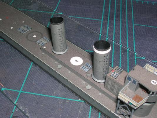
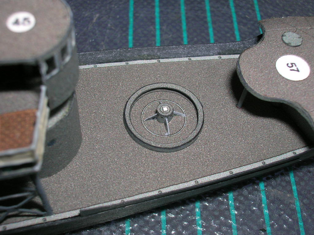
The finished ventilator is mounted to the numbered circle between the stacks. Use the centerline marks and seams to line it up properly.
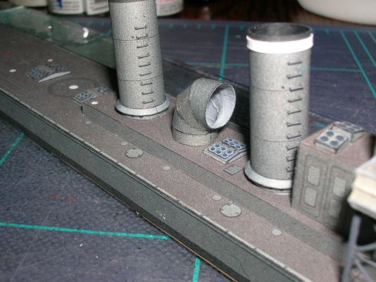
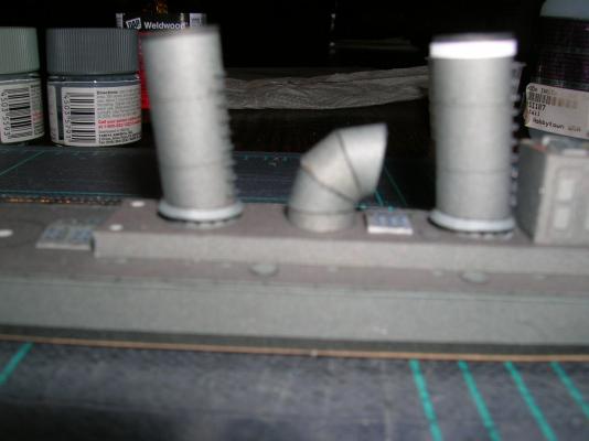
It should be pointed out here that flash photography is particularly unflattering for card models. For example, in the first photo of the finished ventilator, you can plainly see some glue buildup along one of the seams. In reality, that interior part of the ventilator is deeply shadowed in normal light. Same is true for many of the little errors such as differences in color shades, slight gaps in seams, or small glue smudges - all of these are things that tend to get highlighted in close-up flash photos and most are inconspicuous when viewed under ambient light at normal viewing distances. So don't sweat the small stuff!
On to Part VII: Building V108 - Armament
-
Based on your results with the Averof, this should turn out to be an excellent model.
Cheers!
-
No we'll add some aft superstructure parts. As a rule of thumb, we'll work from forward aft, and we'll avoid adding tall, spindly structures, such as the galley stack (61), until later.
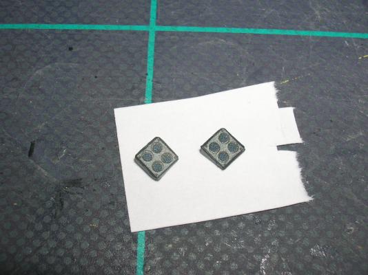
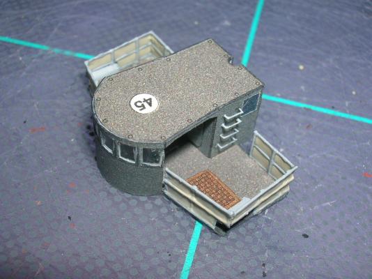
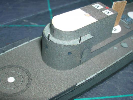
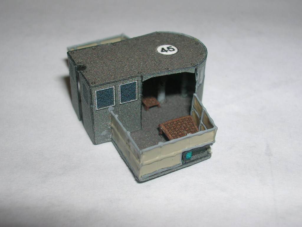
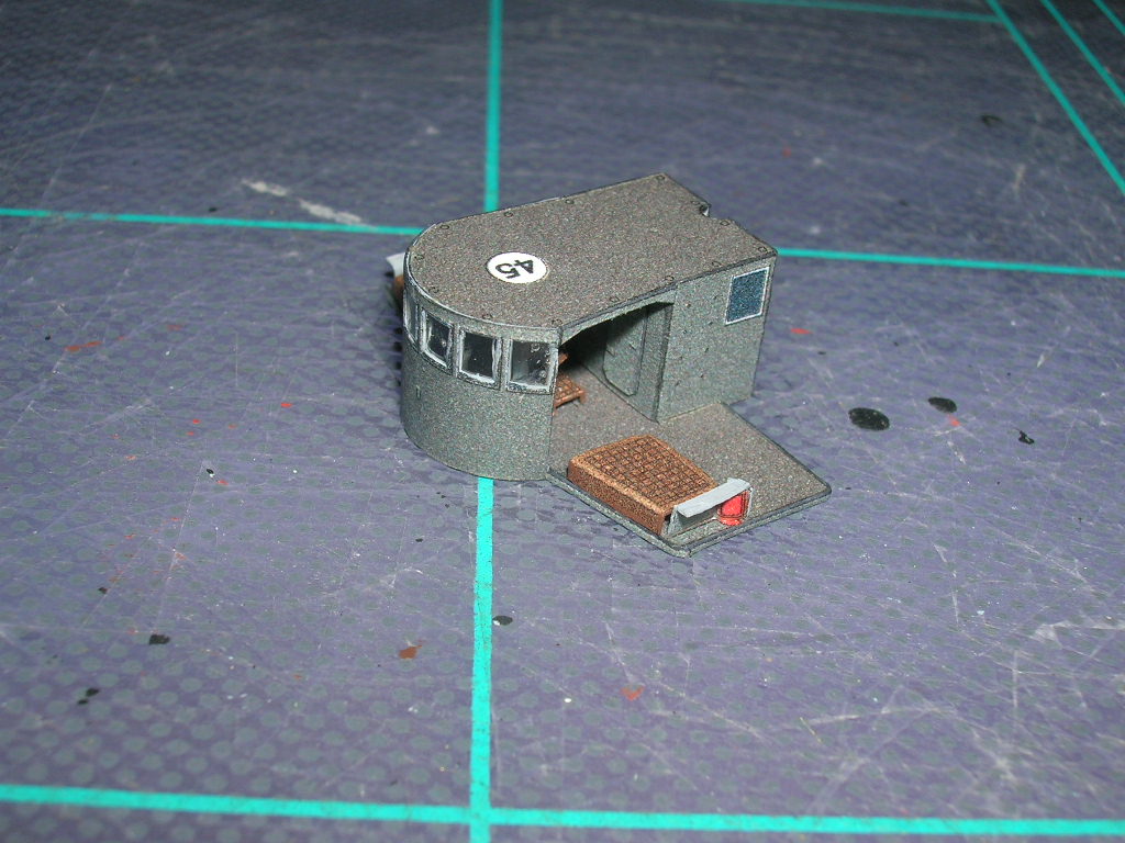
First we'll add the two galley skylights aft of the radio room, parts 35.
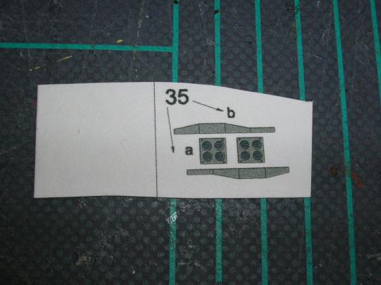
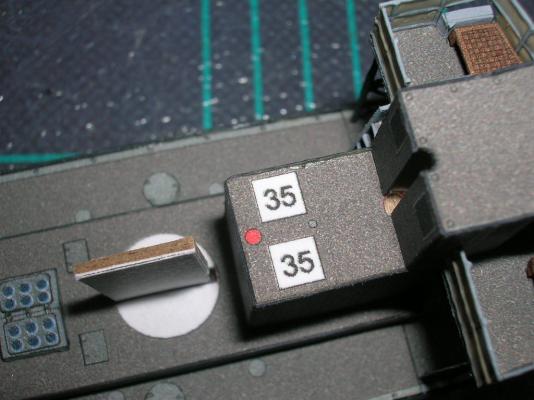
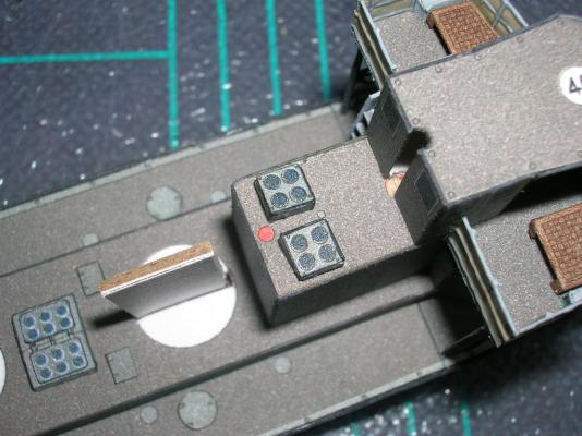
These consist of two frames and two skylights. Score, cut, color, and fold the frames; CA is a good choice for tacking the frame edges where they close together. Add the skylights and glue the finished assemblies down on the locator-numbered squares. The skylights slope down towards their outboard edges.
Next we come to the two stacks, the forward stack (27) and the aft stack (28).
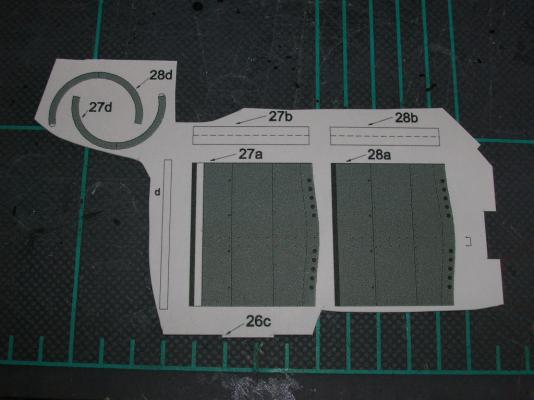
The two stacks are almost identical, so I'll describe the construction of the forward stack, and the construction of the aft stack is basically a repeat.
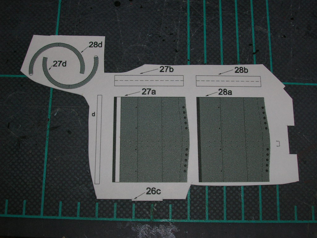
Cut out the parts for the forward stack, parts 27a-27d. There's a misnumbered part in the sequence -- the long, white strip should be 27e. Color the edge of 27a, being careful not to color the portion alongside the white stripe. Next, roll the stack. Remember to lightly moisten the back of the part. Part 27b is a joiner strip; use the 20# bond version of this part. Apply glue to one-half of 27b and glue that half inside one or the other side of 27a.
Apply glue to the other half of 27b and close the stack cylinder. Use tweezers to reach inside the cylinder and pinch the seam tightly shut. The two edges of the seam really need to butt tightly together, or fit problems with 27d may result.
Somewhere in your stash of leftover parts you should have parts 27c and 28c. These are formers for inside the stack cylinders. The diagrams say nothing about where inside the cylinder these should go, so I guessed at it. You can't seat them too low, or the stacks won't fit over the hull profile formers, and you don't want them too high up, otherwise your stack will look like it has a flat cap. I seated my formers about 1/4" down the stack cylinders. Once you get 27c seated, you'll need to paint the inside of the stack black.
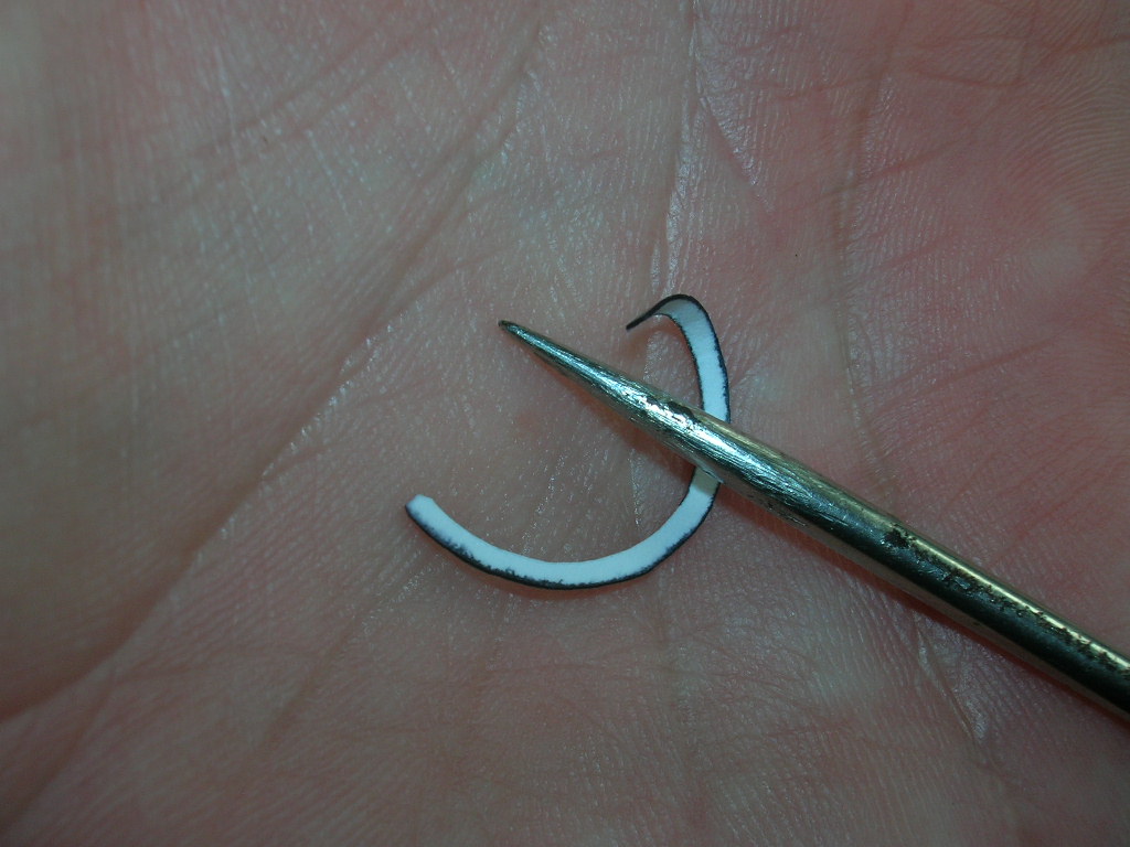
Part 27d is a flange that goes around the lower stack. Cut, color, and roll the flange. This is another conical part, and rolling it with a conical object against a soft surface works well.
On this particular tiny ring, using the glue tab is helpful, and the overlap at the tab won't be terribly conspicuous. When the ring is glued closed, carefully work the ring over the lower stack until it is lined up on the dashed locator line, then apply a small amount of glue to the underside of the flange where it meets the stack. Make sure to line the seam of the flange on the seam of the stack, because both the flange and stack have centerline marks to help line up the stacks on the superstructure. When the flange is done, the forward stack gets a doubled stripe (27e).

The stacks have locator marks for optional rungs. Again, I used some from a photo-etch fret. There are also locator marks for optional guy wires, which I will not be adding (partly because there are no locator marks for the wires on the deck).
The finished stacks fit snugly over the hull profile former. Apply a small amount of glue to the edges of the profile former, then slide the stacks into place, using the centerline marks to get the front and rear edges lined up properly. The ladder rungs should be just off to the starboard side of center.
-
The title of this thread has been edited. Please read the first post here on title etiquette.
With regards to the subject, fictitious kit subject histories, I think this is something of little concern to the manufacturers. Bottom line: as long as the kit sells, what motivation do they have to make sure it's historically accurate? Sad, but true.
-
Now we'll finish up the bridge.
If you look at the port side of the radio room closely, you'll see some locator marks running from deck to roof. These are for grab rails, which are not included in the kit, although there is a microscopically tiny template printed between parts 25a and 28a. The idea is, you have to make your own grab rails from wire, thread, or whatever. The easiest way to make these (notice I said 'make', not 'install') is to use PE aftermarket rails. I used some from a detail set for another model (I'm hoping the fret included plenty of spares!). If this is your first model, you might want to skip little bits like this. On my first card model, my objectives were simple - just to see if I could cut and glue stuff properly. Gluing these tiny parts to the model is an exercise in applying tiny amounts of CA glue and the judicious usage of 'special words'. Working in privacy might be in order.
With this irksome task completed, it is time to mount the bridge to the superstructure. First, we must add three support columns. The easiest way to do something like these is to drill out the locator marks located in the superstructure roof and insert lengths of wire that are longer than actually needed for the finished columns.
Once the bridge is glued on, use tweezers to pull the wires up and glue them into the sockets we previously drilled in the bottom of the bridge deck. Paint the columns after all the glue has dried.
Next come the bridge wing support girders, parts 24c.
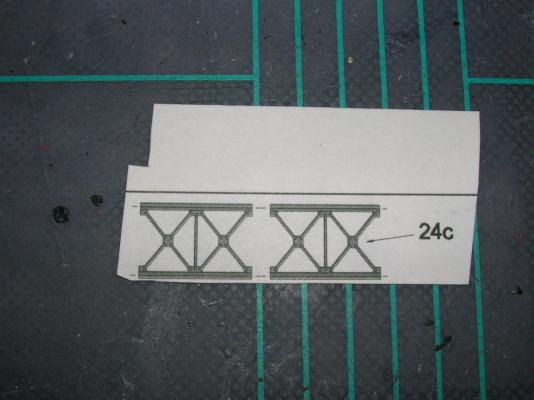
It takes a steady and practiced hand to cut these from the parts sheets. Here's some things to remember: 1) color the reverse side first; 2) remove the inside cutouts first; 3) do as much edge coloring as you can while the girders are still attached to the sheet.
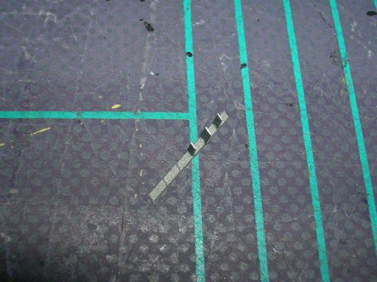
This next step isn't completely necessary, but I wanted to give the girders some additional structural integrity, so I chose to hide some wire behind the main columns, like so:
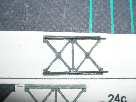
I also coated the entire reverse side with CA glue to give it some added stiffness. Once everything was dry and touched up, I trimmed the wire, leaving ~ 1 mm stubs at the bottom of each column. I then dry-fitted the columns to the main deck and bridge wings, taking note of where the wire stubs met the deck. I then drilled those spots out, creating sockets for the wire stubs to fit into, like locator pins. This eliminates some of the sliding around that might otherwise happen while trying to glue the supports onto the model.
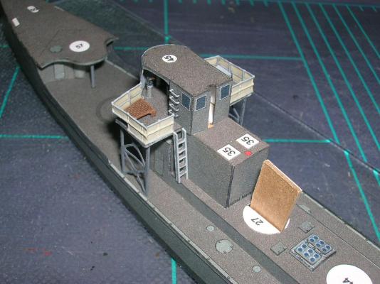
The last bit to add is the ladder, part 34. As I said in a previous post, this is supposed to go on the starboard side, but mine wound up on the port side. Oh, well, lesson learned. The ladder consists of two rails and a set of treads. The rails are two sided, so score and cut out the rectangle containing the rails and their reverse sides, apply glue, and fold. While that dries, you can cut out the treads, which are all together in a continuous strip. Cut out the strip and slice off the individual treads; there are eight on the strip, but the rails only have locators for five. The rails and treads are assembled much like the ladder sets that come in wooden ship kits.
When the ladder is completed, color all the exposed edges and mount it to the aft side of the bridge wing - starboard side, if you did it correctly. The ladder should actually have a handrail on the outboard side, but none is shown on the drawings and no template is provided. Go ahead and add one if you are feeling ambitious!
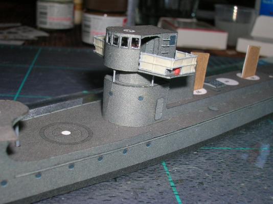
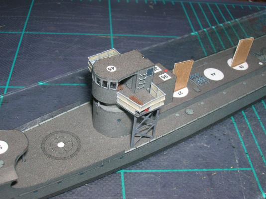
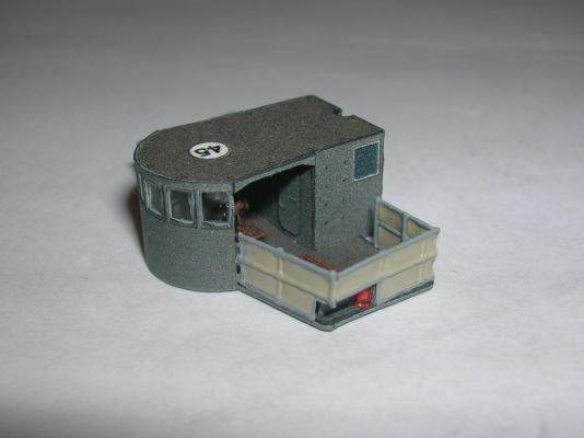
At this point, the completed bridge looks like this:
-
Now for some fun! It is time to add bridge wing railings. If you didn't go for the optional canvas railings, then your railings are already done and you can skip this step. If you chose the optional railings, then read on!
For starters, I happened to have some leftover thread railings from a previous project. Kinda like cheating, I know, but this is why we modelers save leftover bits, isn't it?

These thread railings were made on a jig consisting of a template glued to a piece of stiff corrugated cardboard. The template was from a Paper Shipwright kit, and David at Paper Shipwright has a free railings template available at his web site. I will need to make many more railings for this model later on, and I will give a detailed description of their construction at that point, but if you can't stand the wait, just download David's template and follow the instructions that come with it. Another option is to purchase laser-cut or photo-etched after-market railings.
Before moving on, I will point out that my scratch-built railings don't match the printed railings exactly. For one thing, the kit railings decrease in height between the front railing and the side railing; this I did not attempt to replicate. I also did not try match the correct number and locations of the stanchions. The emphasis here is on improving the overall look of the model, even if it is not 100% true to the original. Making the railings completely accurate would have added considerably to the complexity of the task. The chance your model will be observed and critiqued by an expert on the design and construction of torpedo boats of the Imperial German Navy is extremely remote!
Step one in making the canvas railings, once you have the basic thread railings in hand, is to fill the spaces between the rails with diluted white PVA glue. As I said in a previous post, I wasn't sure diluted PVA would dry hard enough for window glazing, but it's fine for making canvas railings.
Once the glue dries thoroughly, the "canvas" can be painted a suitable color. The paint need only be applied to the front side of the railings; the tint will show through to the back side.
I didn't attempt to bend the railings where needed. It is far easier to cut the railings into properly sized panels and install them one at a time. Openings need to be cut out for the navigation lights, and the port railing needs to end short of the radio room, leaving a space in the back for a ladder. (NOTE: The ladder is actually supposed to go on the starboard side; I missed this in the diagrams. Looks my captain made an executive decision to move the ladder to port!)
Once cut, installed, and touched up, the railings look something like this:
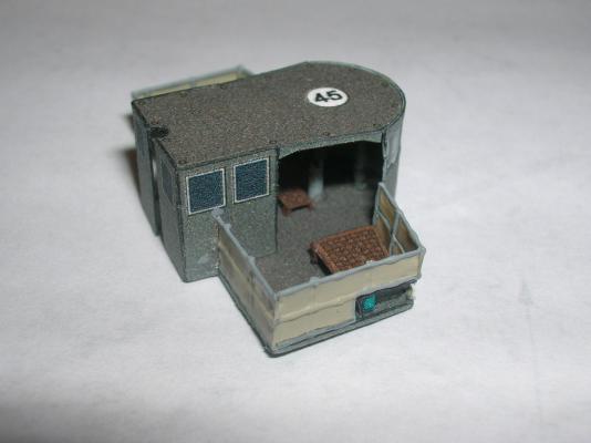
To me, the scratch canvas railings are a significant improvement in the looks of the model and well worth the extra effort needed to make them. But again, it is no sin to omit them if this is your first (or even second) card model and you feel they might be too far out of your comfort zone. The printed railings will suffice nicely.
-
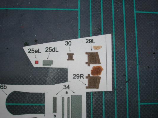
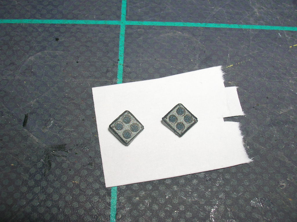
Time to add the bridge wing details. These include the navigation light, parts 25d and 25e, and several gratings, parts 29 and 30.
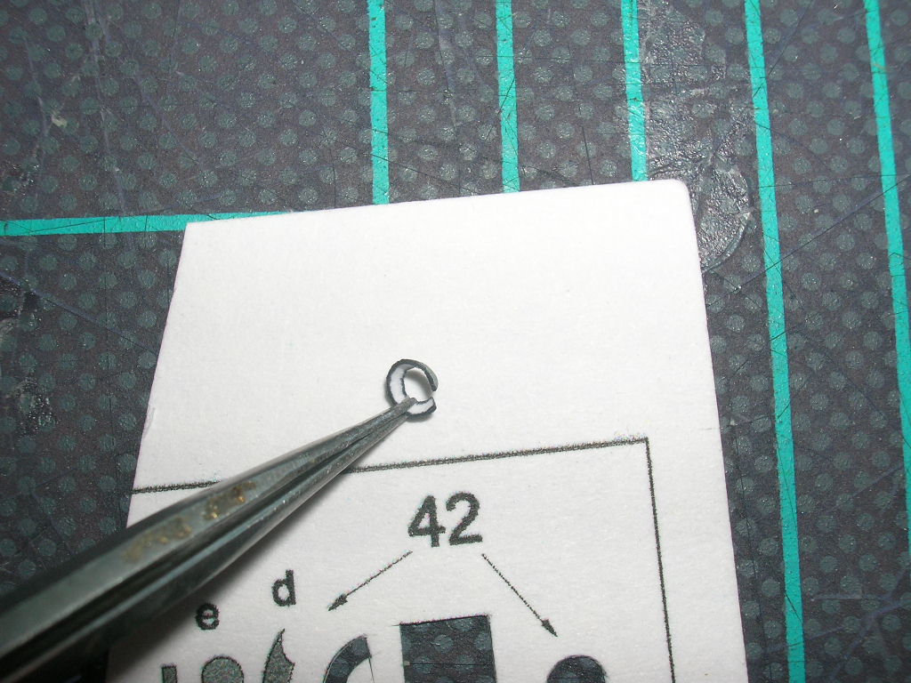
The navigation light housings present a minor decision - there are two ways to fold them, and either way you have to color the reverse side. So, I will use these to introduce yet another new technique. So far, all the fold scoring we have done is for parts that fold down, but what do you do if you have a part that needs to fold up? After all, there are no fold lines printed on the reverse of the part. It seems like the direction of the fold shouldn't matter, but it does - scored lines definitely want to fold one way more so than the other. When you fold up from a scored line, a tiny pucker is created along the folded seam; 99% of the time this pucker might not make a difference, but for really tiny parts, that pucker might result in not being able to place another part correctly.
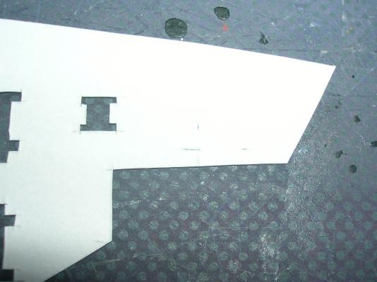
So, here's how to score the reverse of a part, using a navigation light housing (25dL) as an example. Make a small cut right at the end of and exactly in line with each of the printed fold lines, like so:
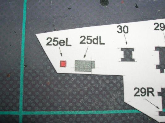
Flip the part over - now the cuts act as two points to define a line. Connect the points with your scoring tool (I used the cutting technique on these because of their size) and you're ready to proceed.
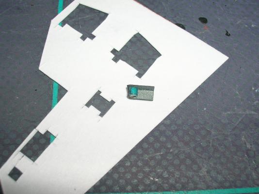
Now, if you use this technique, 25dL actually becomes 25dR and vice versa -- doesn't really matter which one is which as long as you get the orientation of the housing correct on the bridge wing, along with the proper color of light. Finishing the navigation lights requires folding up and gluing the two sides of the housing, coloring the reverse side, and adding the light lens (25e). Use the 20# bond version of the lenses, if you have them, or delaminate the card versions for easier forming. Here's a finished light:
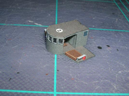
Next we need a few gratings, parts 29 and 30. These are pretty straightforward - score, cut, color, fold, done. Part 30 goes abaft the wheel, while parts 29 and the navigation lights go on the bridge wings - there are locator marks for all of these. Make sure the port light is red and the starboard is green. If you're doing the modified railings, make sure you don't glue these parts right on the edges of the bridge wings - you need a little room to install the railings.
-
I thought about using PVA glue, but I wasn't sure if it would dry hard enough. I applied the top coat from the inside mainly because a) the applicator brush was too large to keep everything entirely within the frames, and b ) I didn't want to see what would happen if I tried to wipe off any excess on the printed side of the part. As with any medium, there's usually more than one way to do these various tasks with card, so thanks for sharing alternative methods.
With regards to very small parts, especially these detail parts that are many times smaller than a fingertip, it pays to handle them as much as possible with tools, such as tweezers, instead of fingers. I even use my knife tip for picking up small parts from my cutting mat - a light stab to pick up the part doesn't leave a visible mark on the printed surface.
Cheers!


Part VIII: Building V108 - Miscellaneous Bits
in Card and Paper Models
Posted
So, how do our thread railings look on the model? Judge for yourself:
Adding the railings consists of measuring off the right length of railing to add, adding any extra stanchions that might be needed due to cutting to length, and gluing the railings to the model. I use PVA for straight sections and CA where necessary to tack down any sharp curves. I brush the PVA onto the deck where the railing goes, not to the railing itself - these springy railings are a great way to spread unwanted glue on your model.
Here's the finished forecastle railings:
The forward flagstaff is a short length of wire.
Anywhere there are angled bends in the railings, I prefer to cut the railing at the joint and glue down two separate panels. Unlike photo-etched metal or card, thread does not like to make nice, crisp bends.