Philg88
-
Posts
166 -
Joined
-
Last visited
Content Type
Profiles
Forums
Gallery
Events
Everything posted by Philg88
-
 Thanks for the input. Unfortunately, the hole in the fore top is currently too small for the line to go back through it. Maybe I can extend it slightly so that can be done but there is not much room. I shall ruminate and cogitate for a while and see what can be done. Cheers, Philip 🍺
 -
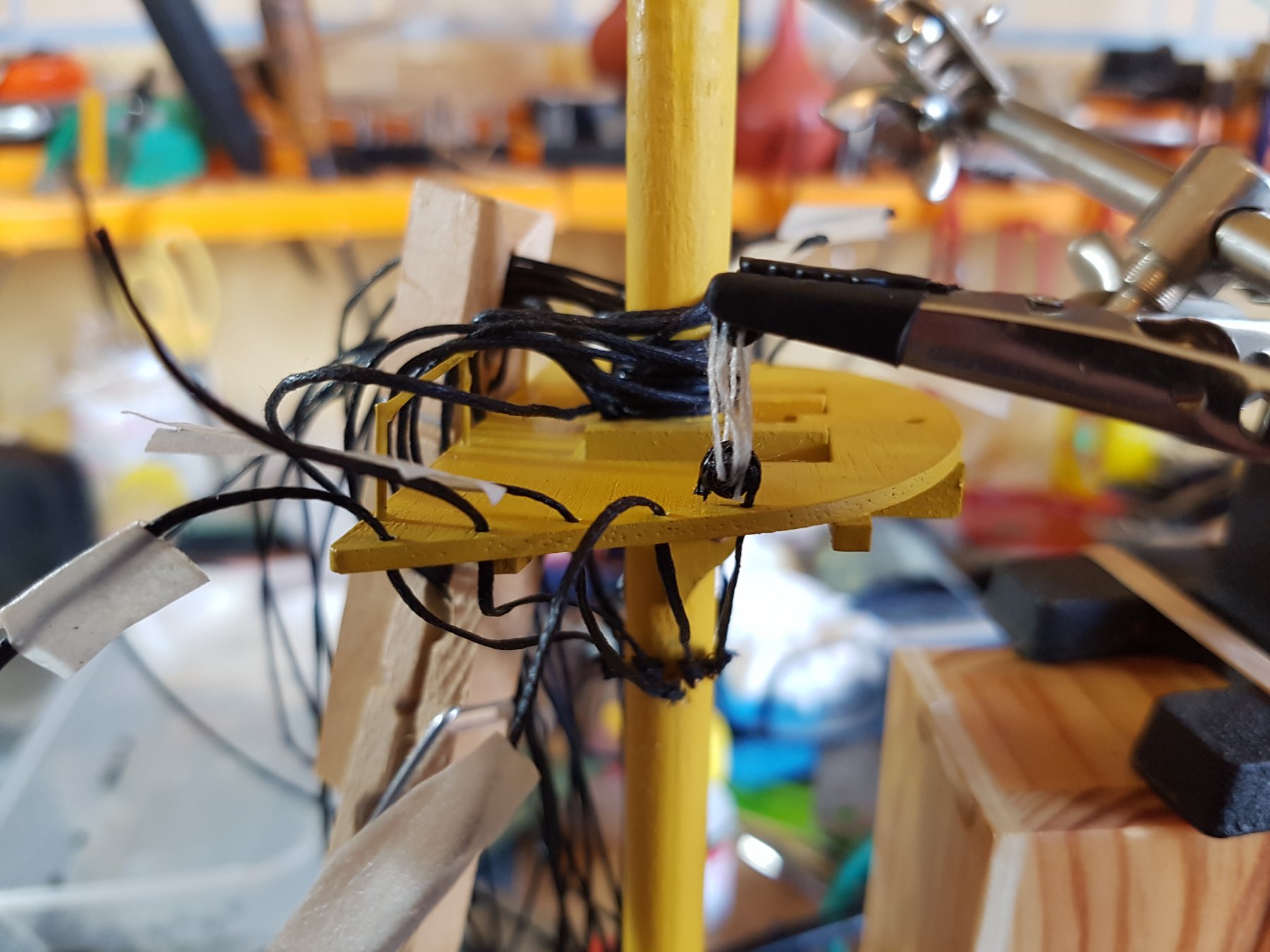
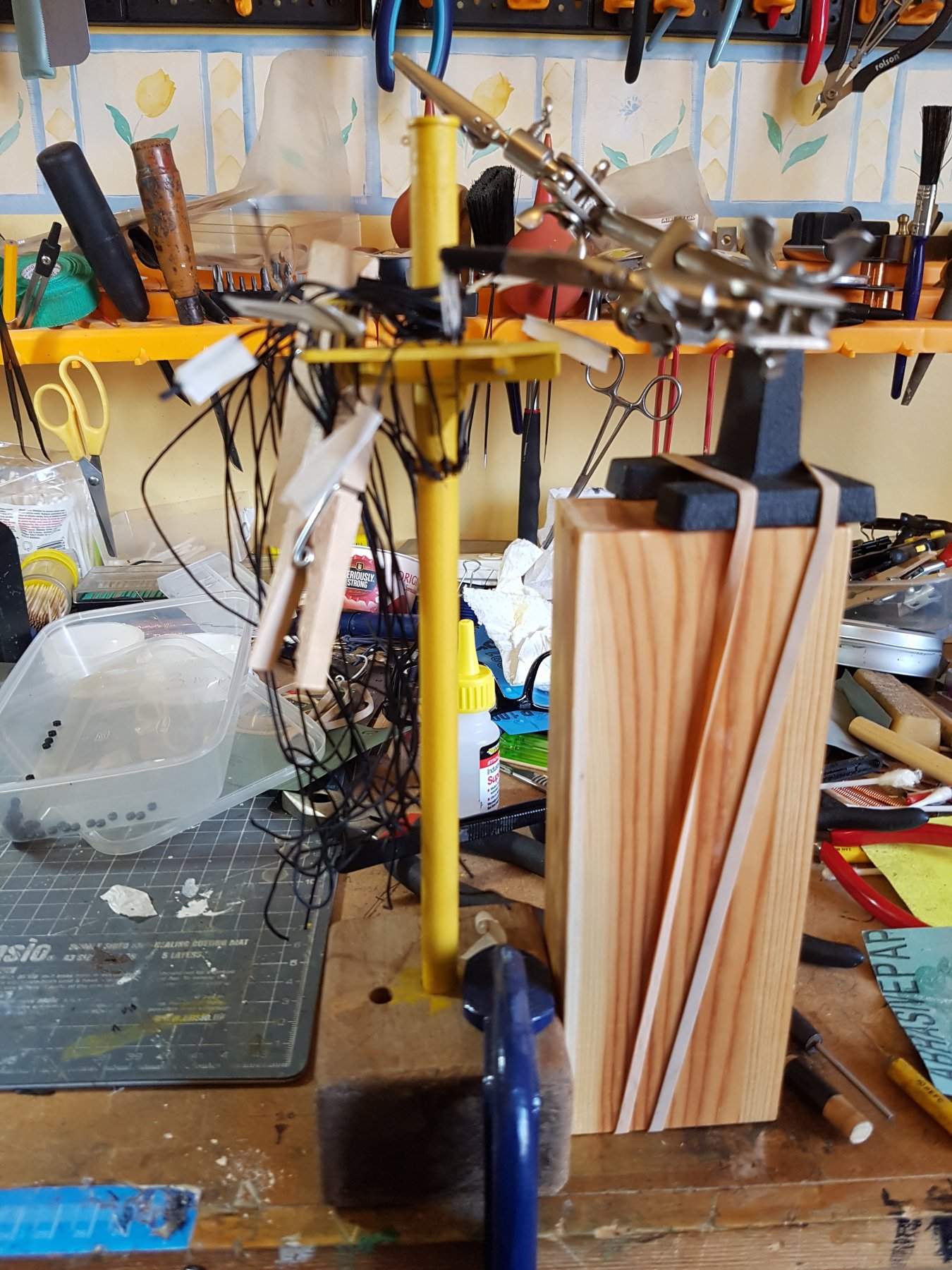
This is the rather Health-Robinson jig I have created to attach the dead eyes to the fore top. Seems to work OK. Note the grips on the crocodile clip are covered with heat shrink to prevent damage to the painted dead eye.


-
Thanks for the encouragement guys. Rigging is proceeding and although tedious quite satisfying. Will post some pics when the foremast is done.
-
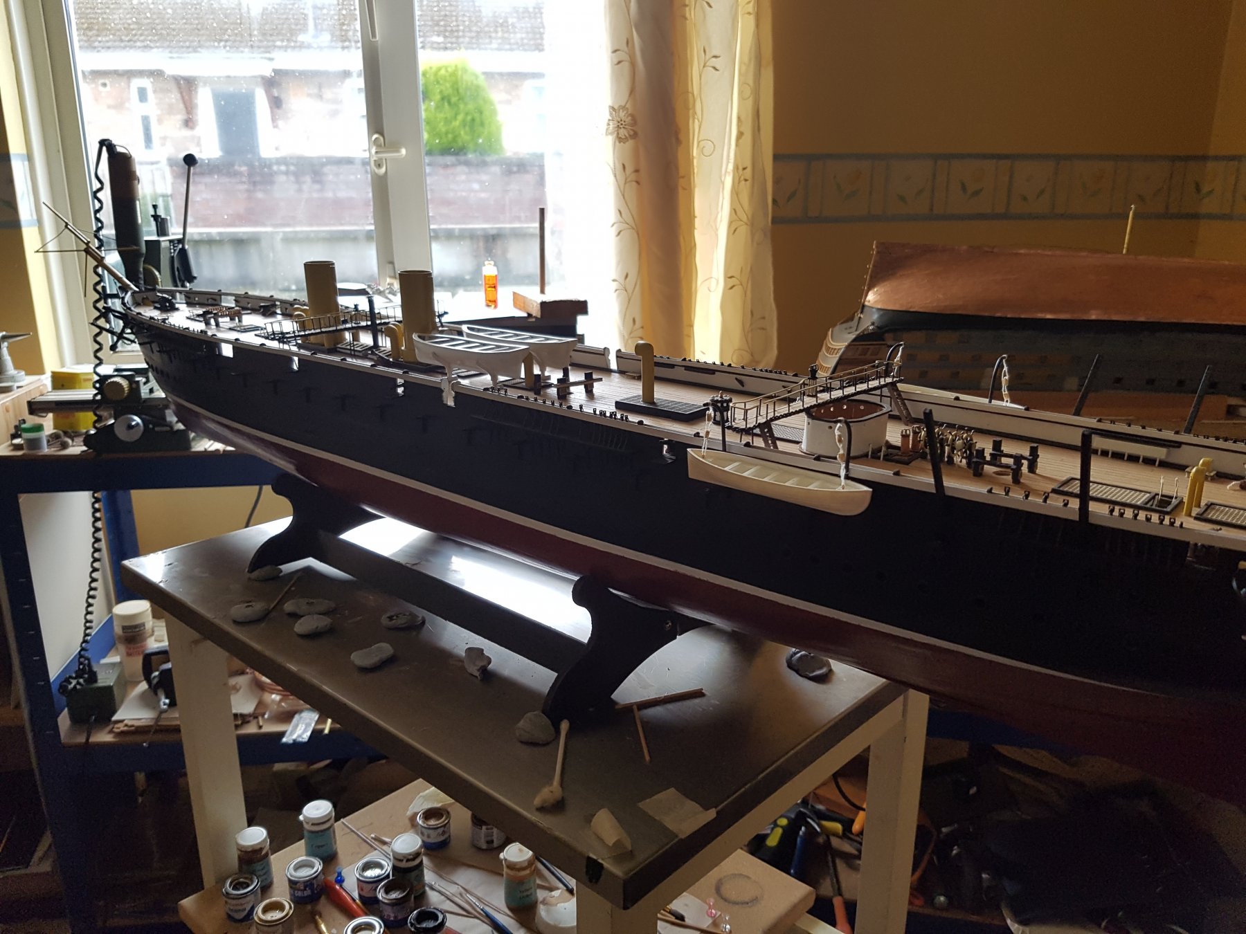
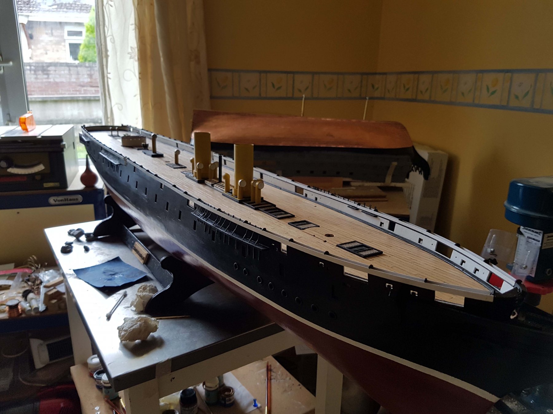
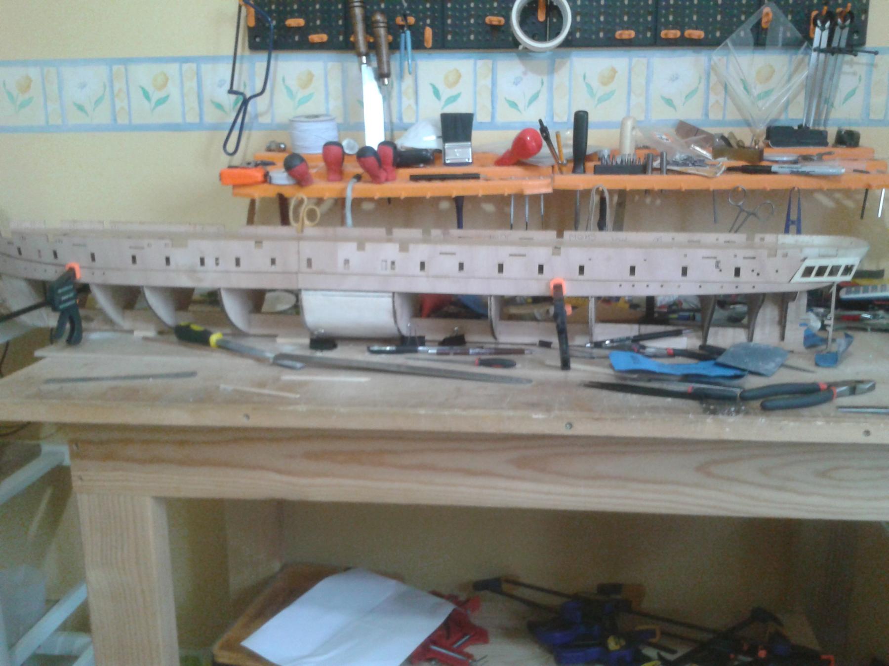
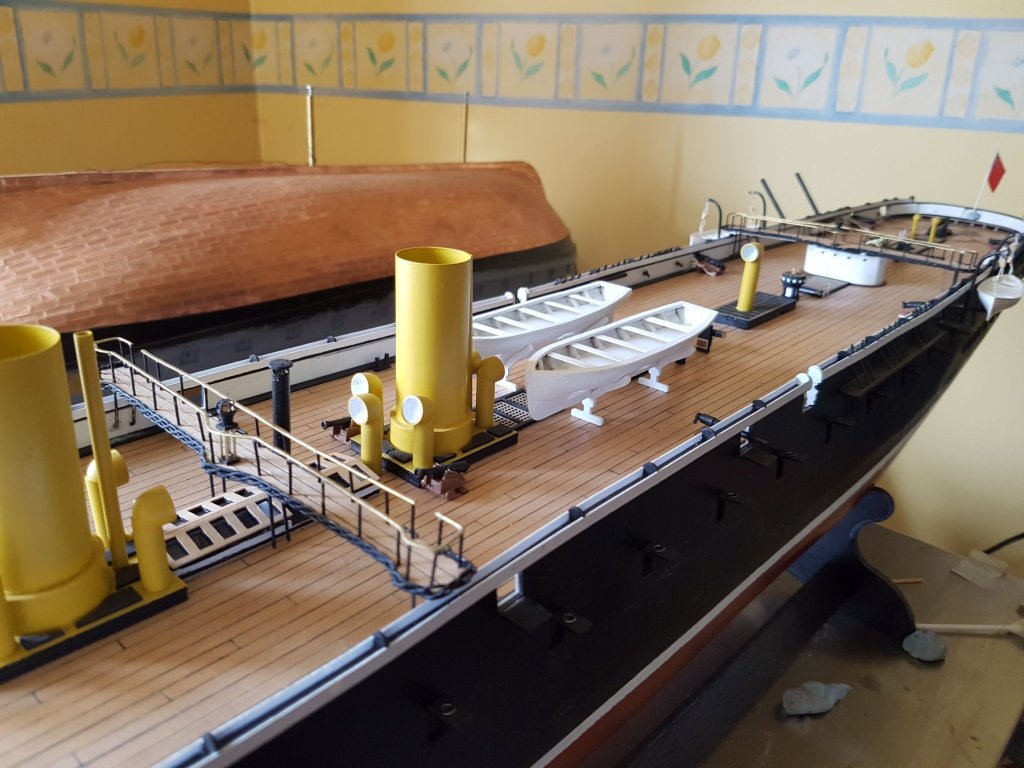
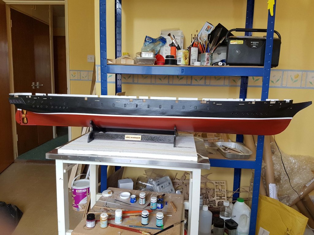
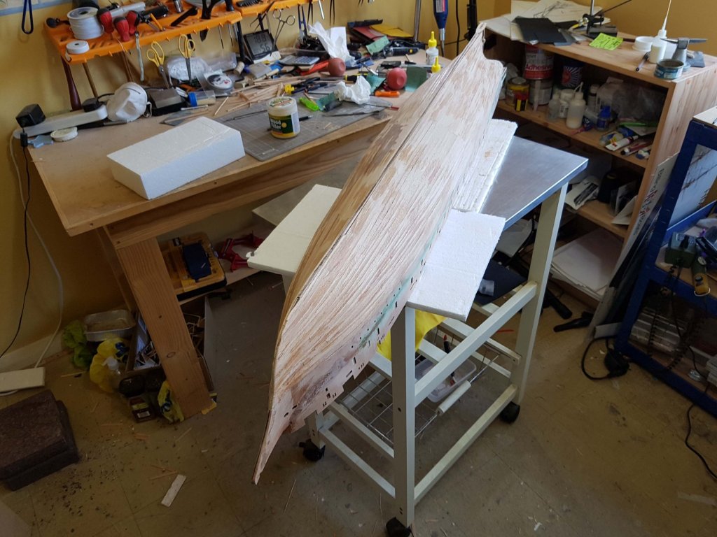
OK, the build hasn't stopped -it's just proceeding at a glacial pace. Boat Construction General Pics - alas she is so big it is almost impossible for me to take a full profile photo


-
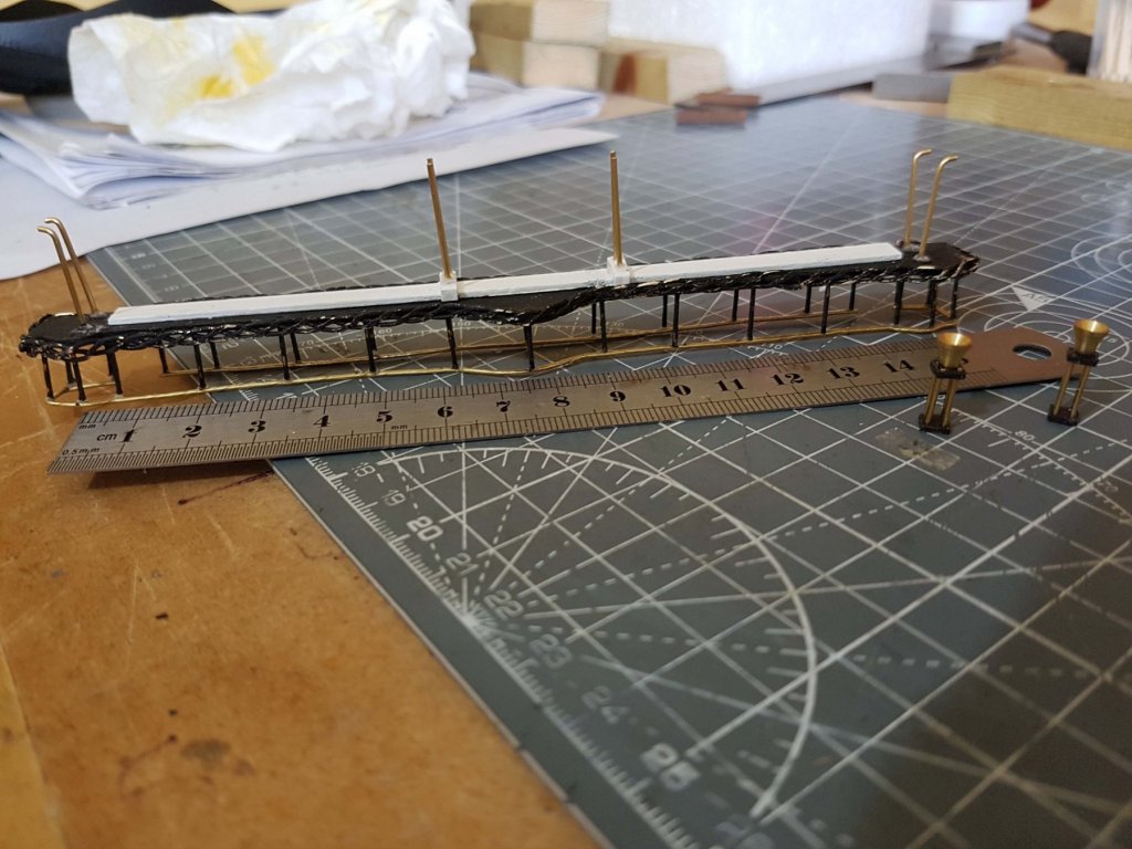
Forward bridge complete and fitted. This is a time consuming and fiddly job to say the least! The decoration that runs around the bridge edge is made by twisting three strands of 1 mm brass wire together then hammering them flat on an anvil block. The handrail is 2 mm brass wire hammered flat. These were then bent into shape using a forming template. Billing's instruction for the edge decoration was to use rigging thread - yuk!
-
Thanks Steven, M33 may well be the pigeon. Once the Warrior is finished we shall see. Best, Philip
-
Thanks Keith, I suspect vicky is a bit jealous of all the attention her big sister is getting so she snuck into the pic out of spite Cheers, Philip
-
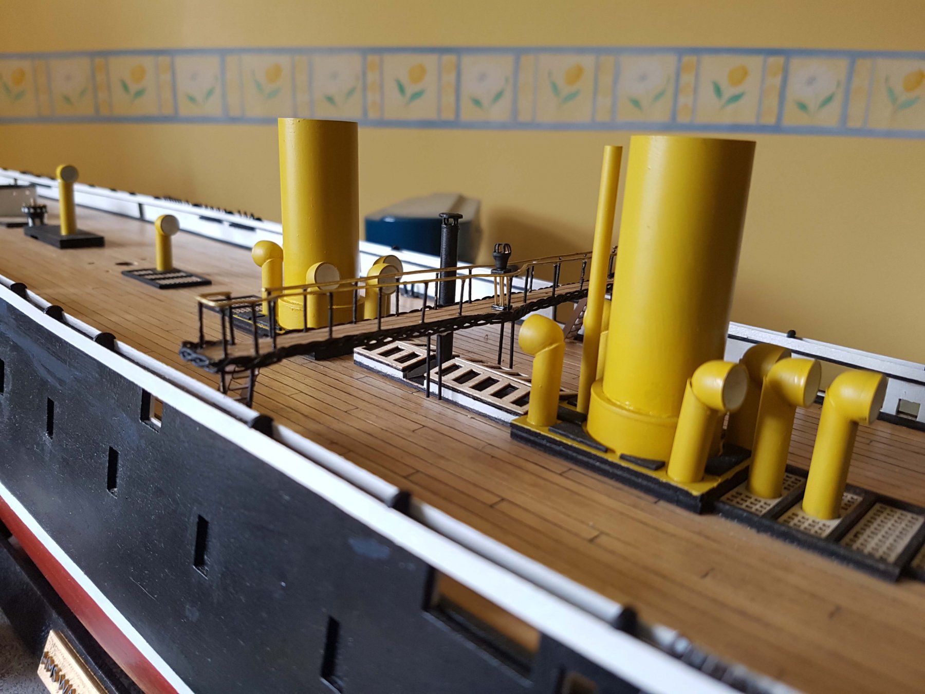
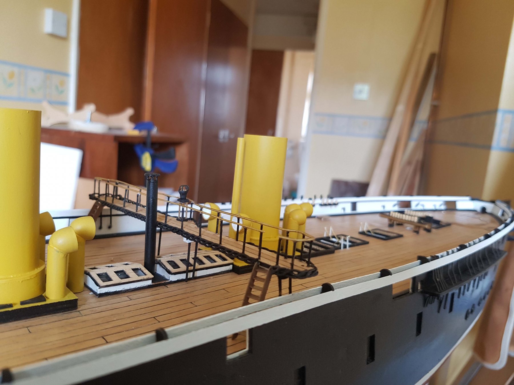
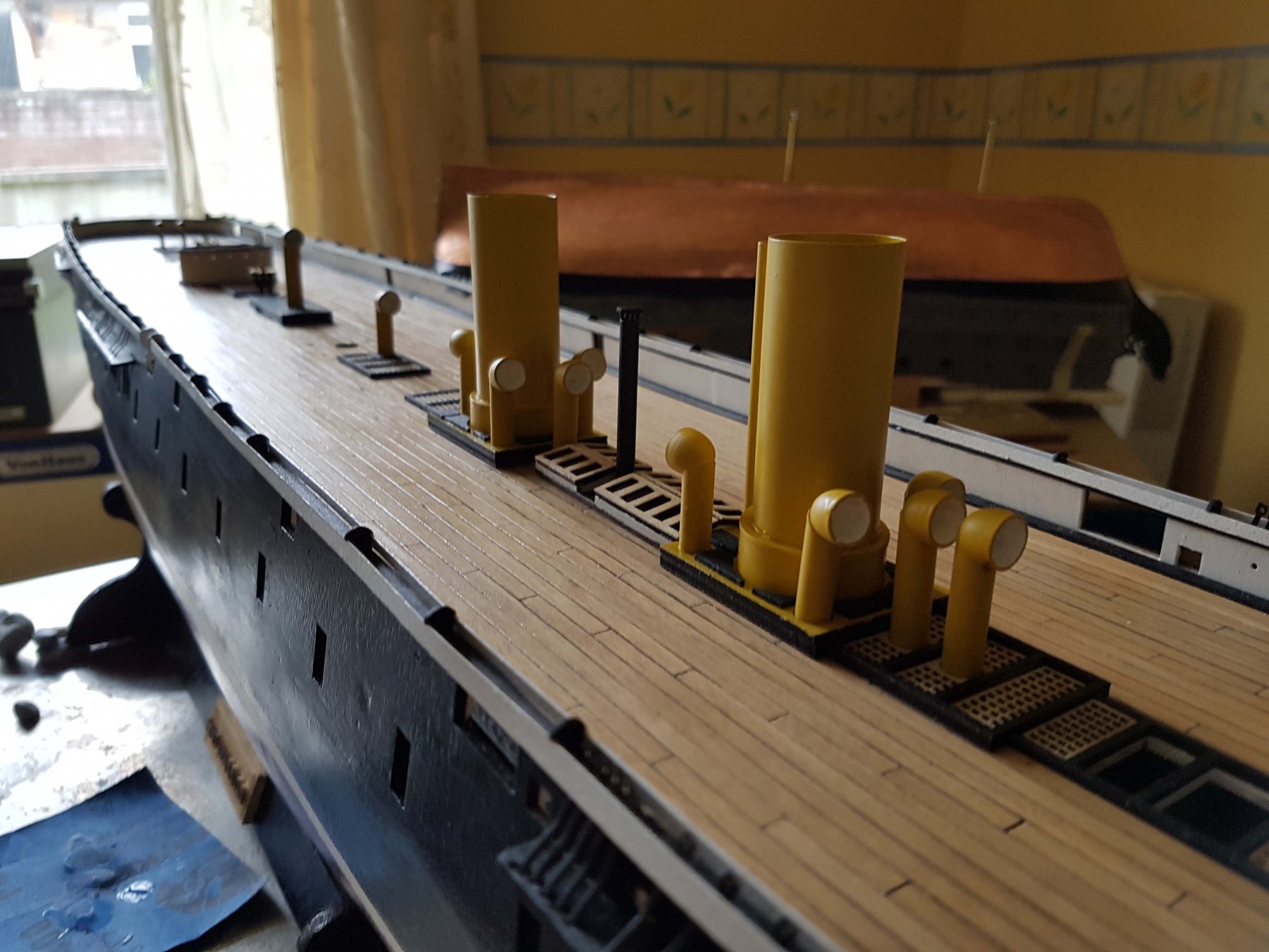
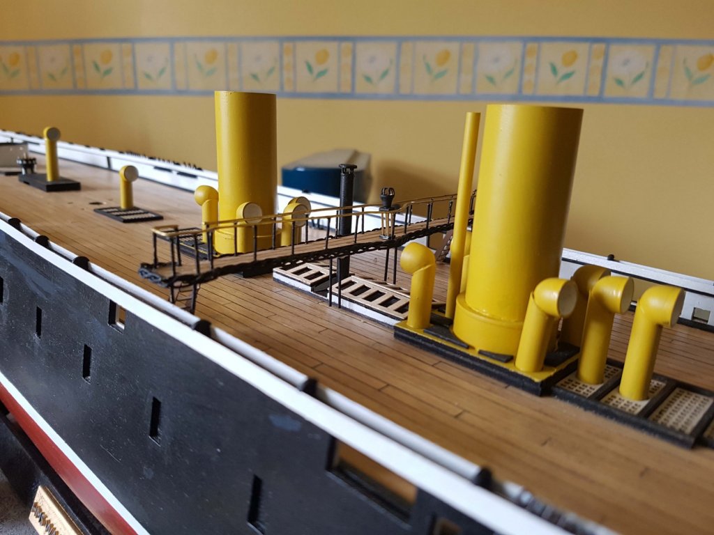
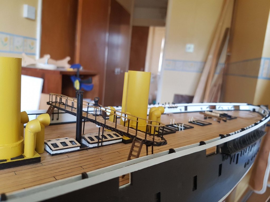
Progress on the superstructure ...


-
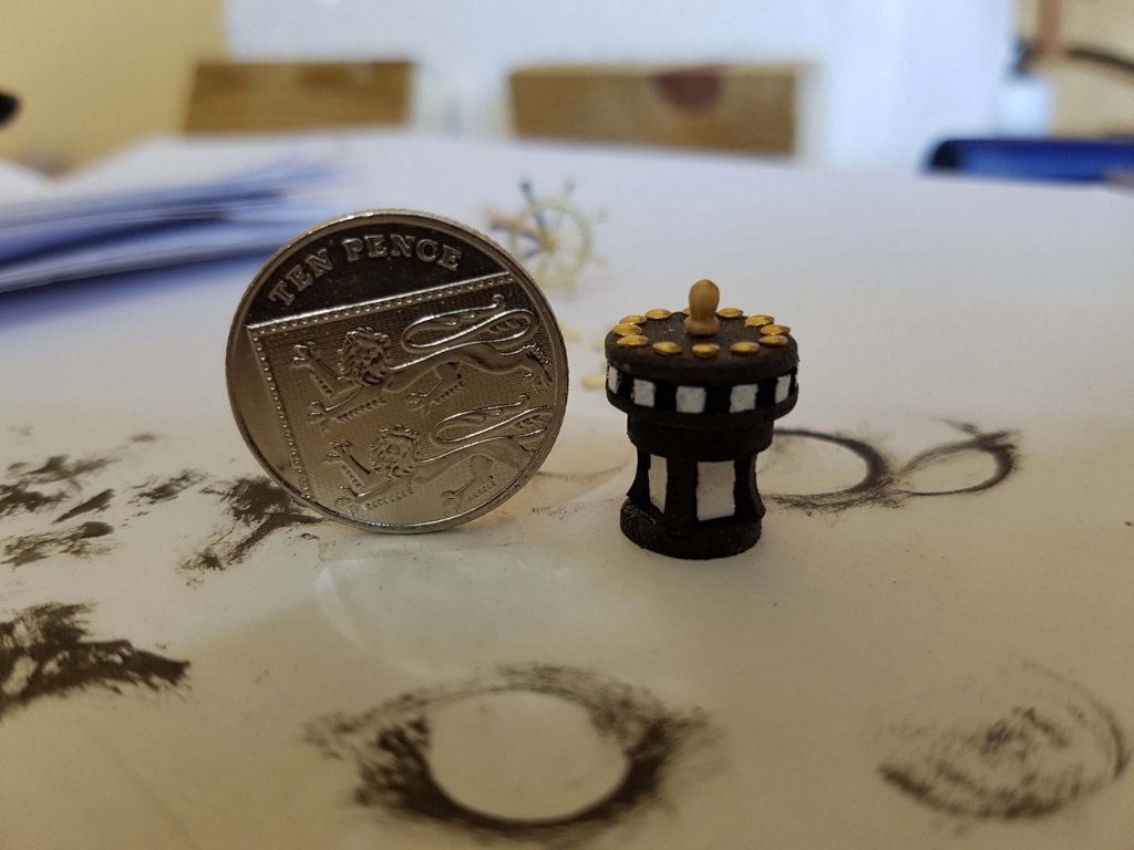
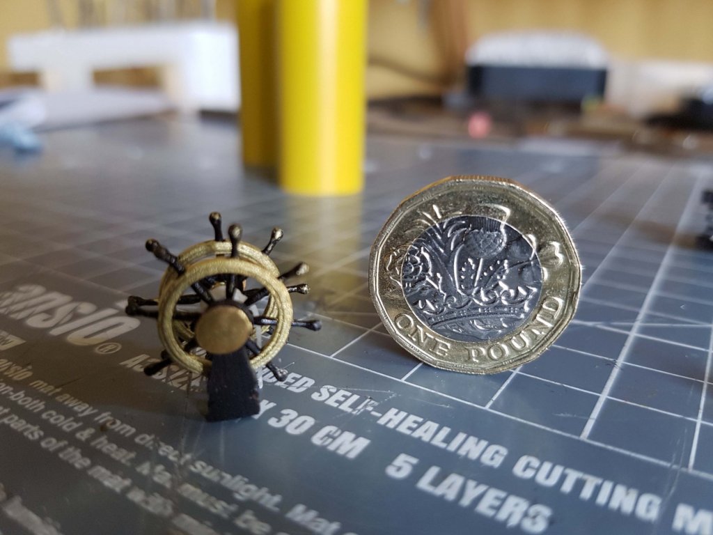
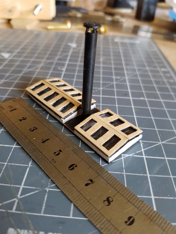
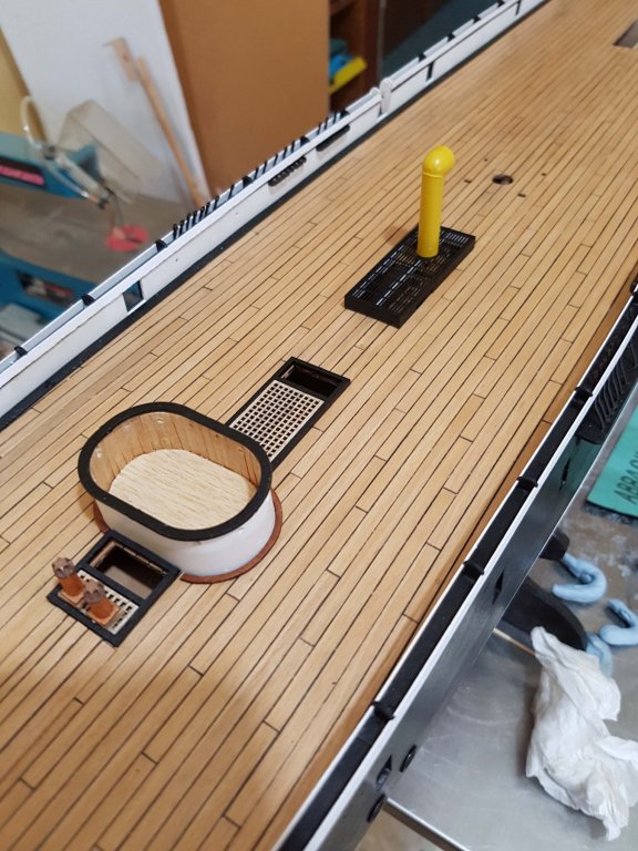
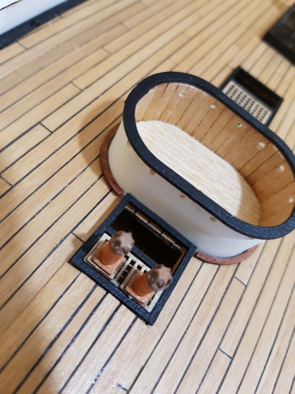
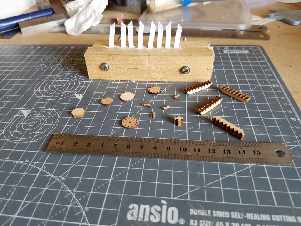
Chainplates and handrails now all fitted so its onto the deck. I ended up making the rifle proof conning tower out of plasticard, as I defy anyone to bend the 2mm plywood provided to the required shape without it delaminating, splitting or warping. It was then lined with 0.8x3mm stripwood. Conning tower, compasses and main vent dry fitted to the deck Now fabricating the deck stairs and capstan.

-
Aye Aye! There is a deadeye pair attached to the top of each one, which then connects to the shrouds. On the real ship the connection was hidden in the middle of the double handrail. I thought about doing that but there is only about 3mm to work in so with a 1mm gap either side its nigh on impossible.
-
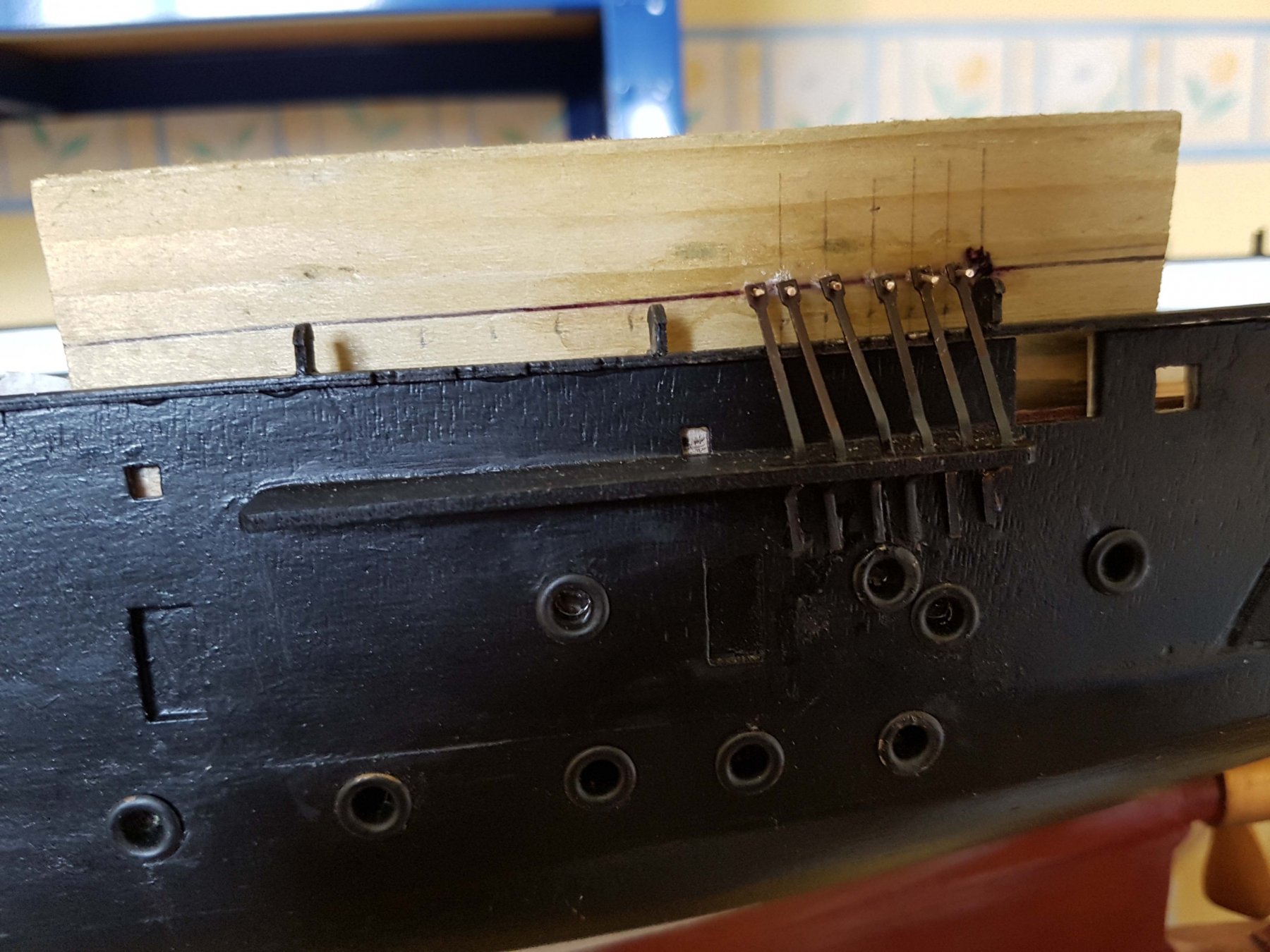
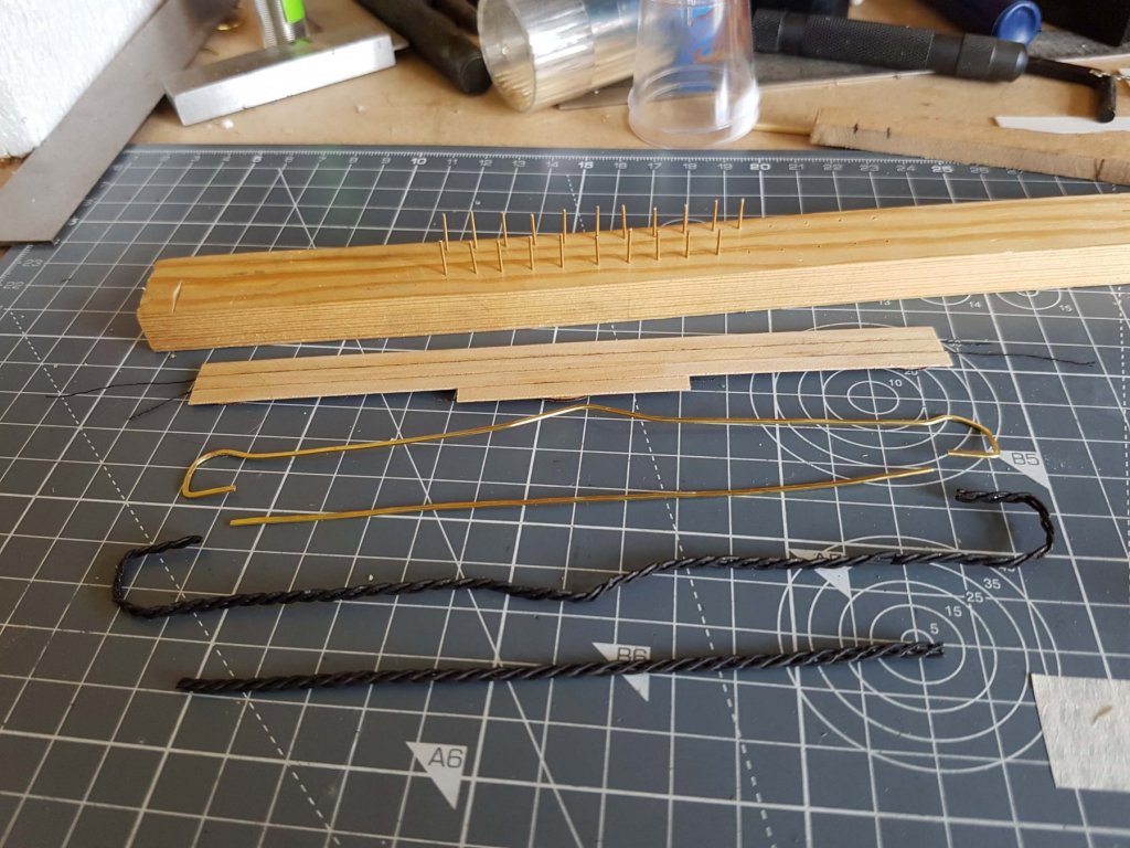
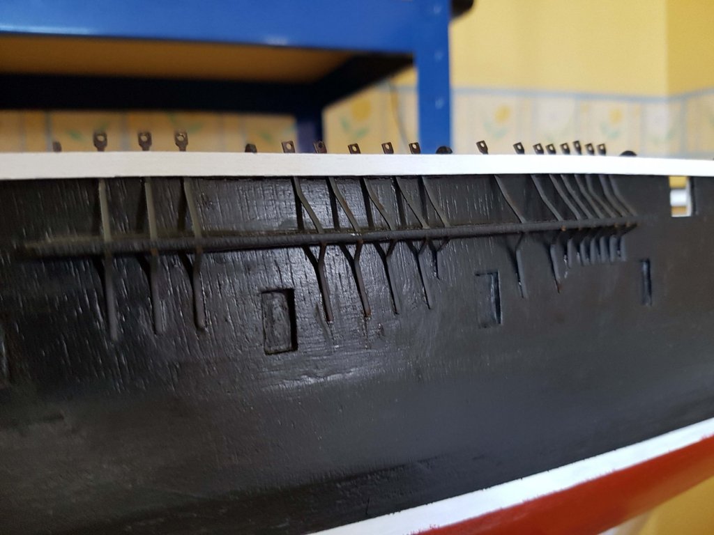
Made jigs for each of the chain plate groups out of 2x1 timber and brass wire (80 in total). Port side is done and the upper double handrail fitted.

-
Thanks for pointing that out, I hadn't noticed it! Weird, must be a reflection from something as the acetate in the windows is clear. Cheers, Philip
-
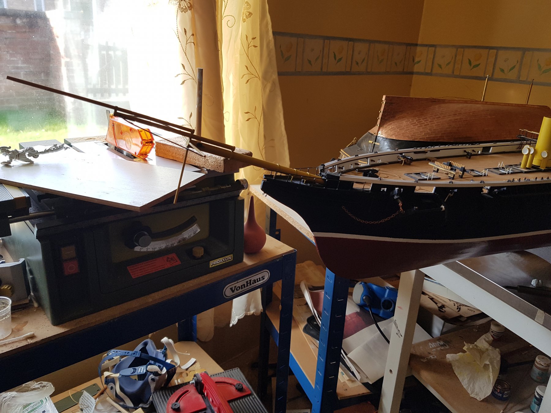
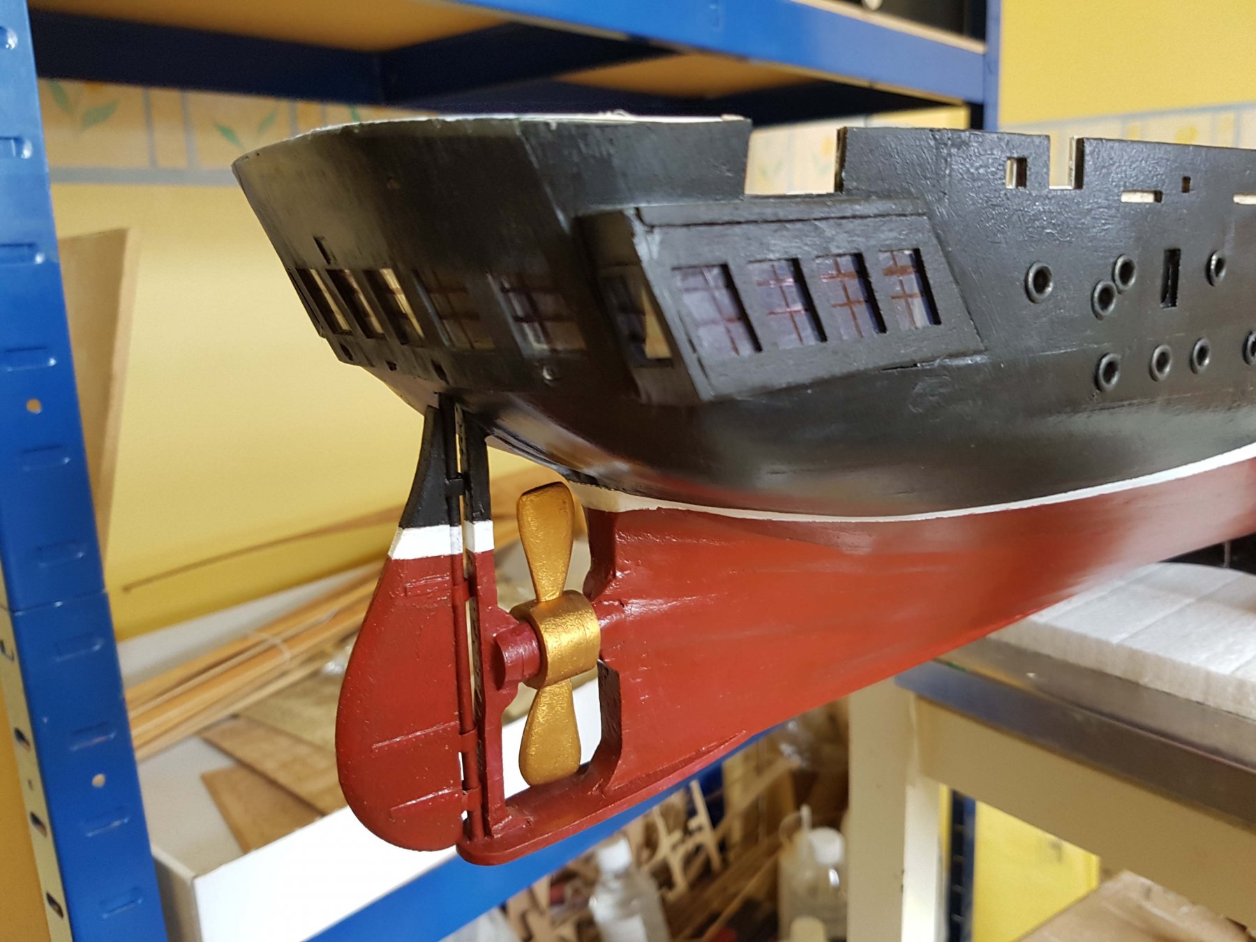
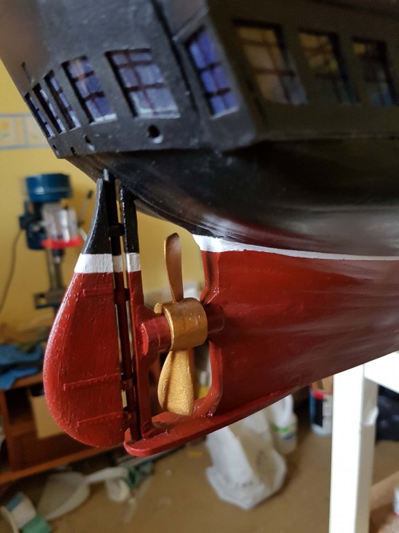
OK, Having checked the reference books I have, there was definitely a pitch on the propeller. So I've modified the blades, thankfully with no damage. As a side note, the propeller pitch wasn't adjustable - when the ship was under sail it would be hauled up into the well in the stern. As the model is in steam mode (because the funnels are up) the representation of the propeller is now correct. Thanks for the input guys! Best, Philip
-
Hi Christos, Thanks. Yes, she is in Portsmouth. There is a webcam at the top of her mast from which you can see the Victory moored not far away. Link is here. Cheers
-
Thanks Gerhard, I see what you mean. I think the blades should be mounted at 45% to the shaft. I will try and fix but it may not be doable without damage in which case it will have to stay as it is. Best, Philip
-
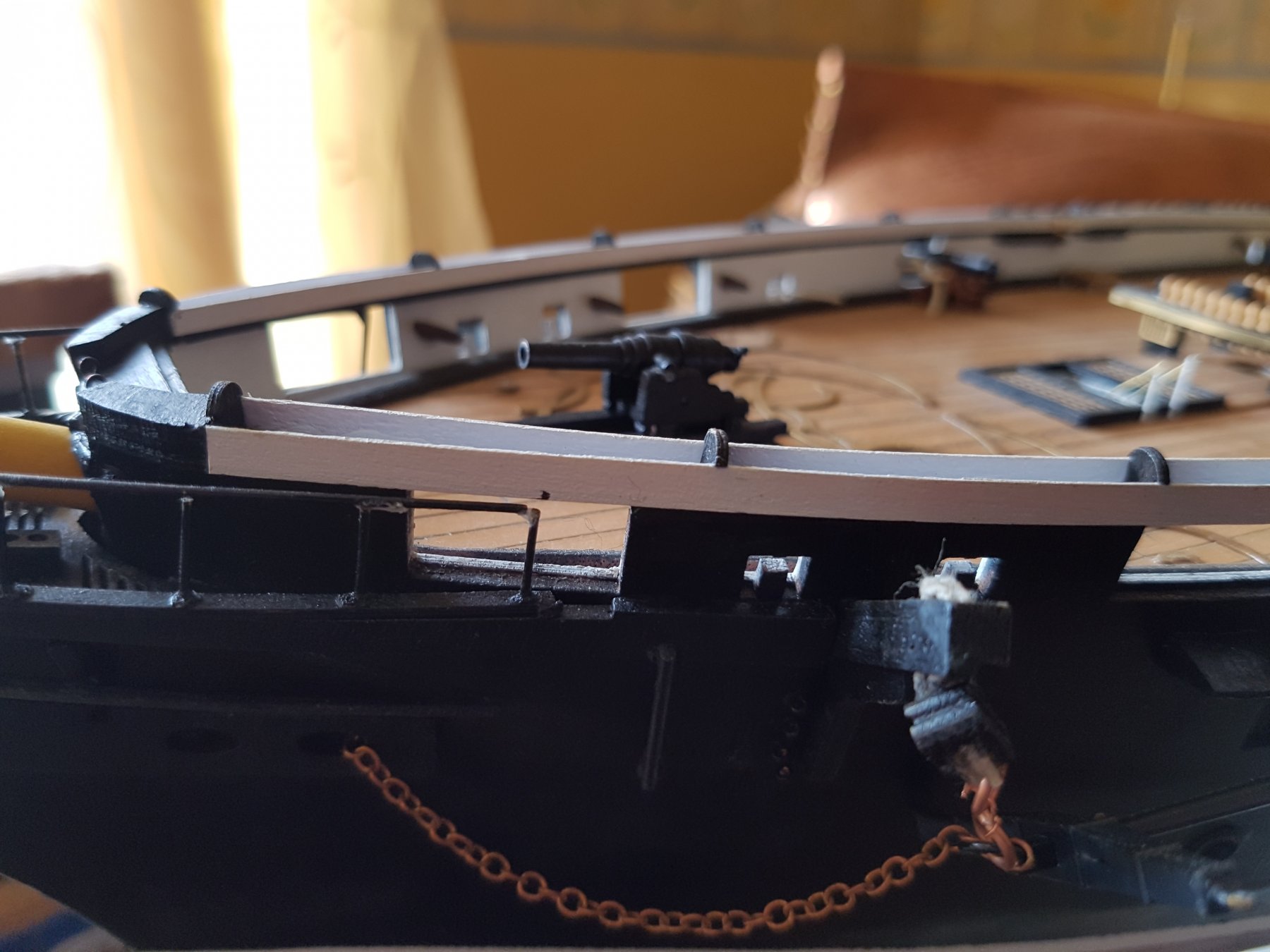
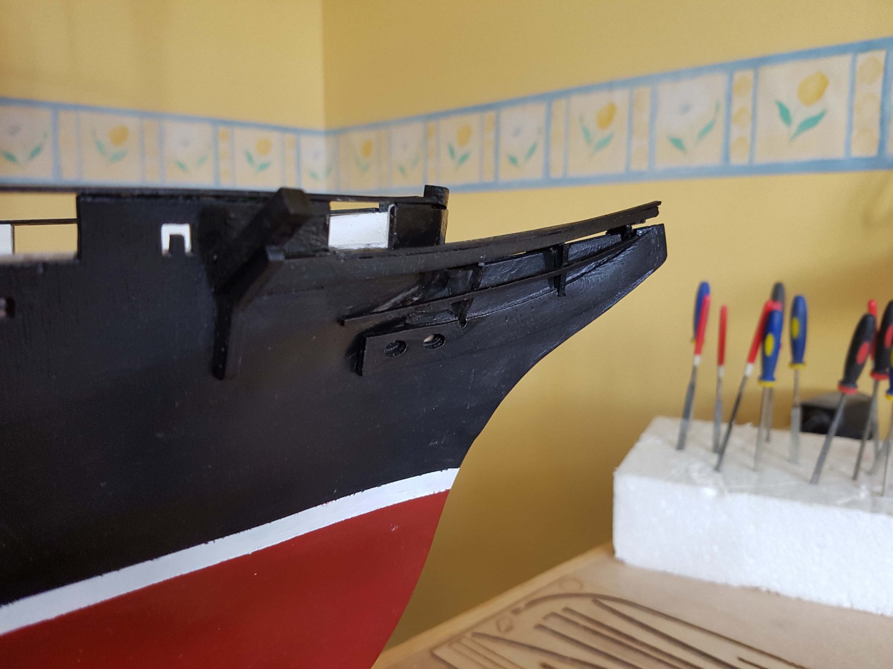
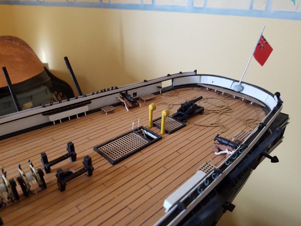
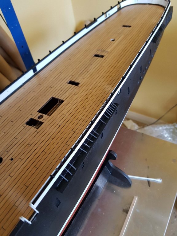
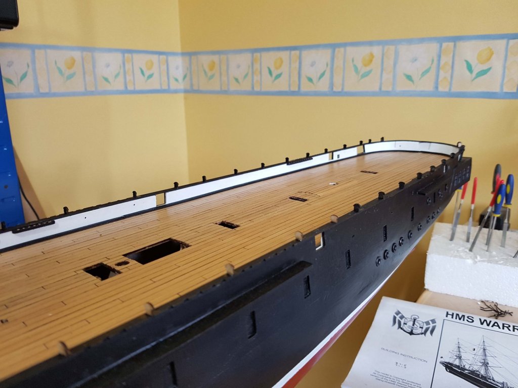
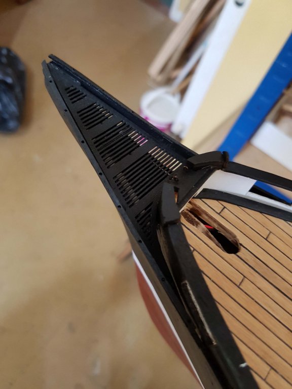
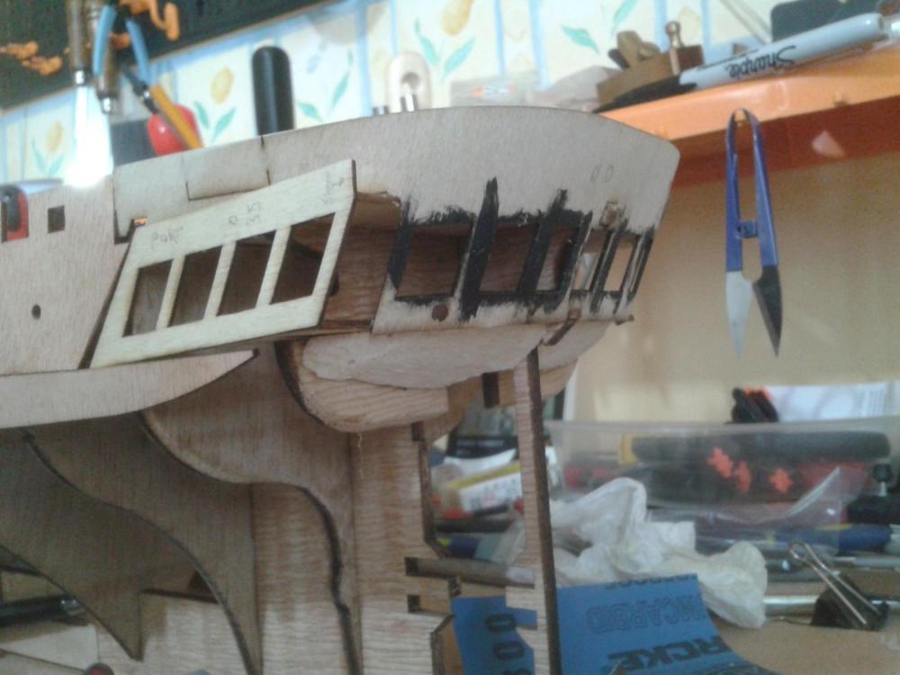
Thanks for the kind comments guys, Some more progress ... Lower hand rail going on Beakhead progess ... 62 upper rail supports fitted - these were held in position with tape then CAed into place, very fiddly. Note chain boards and belaying pin racks also fitted. That's about it for now.

-
Thanks Pat, but after rigging the current two I think a ship with no masts is more likely. Possibly something like this. best Philip
-
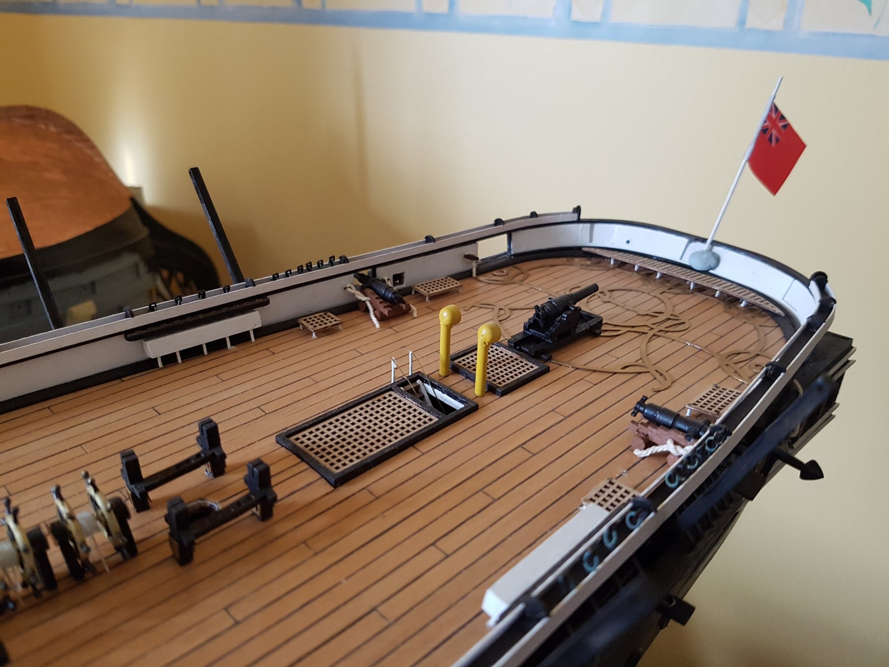
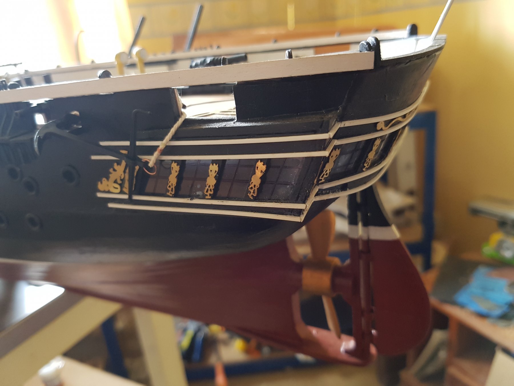
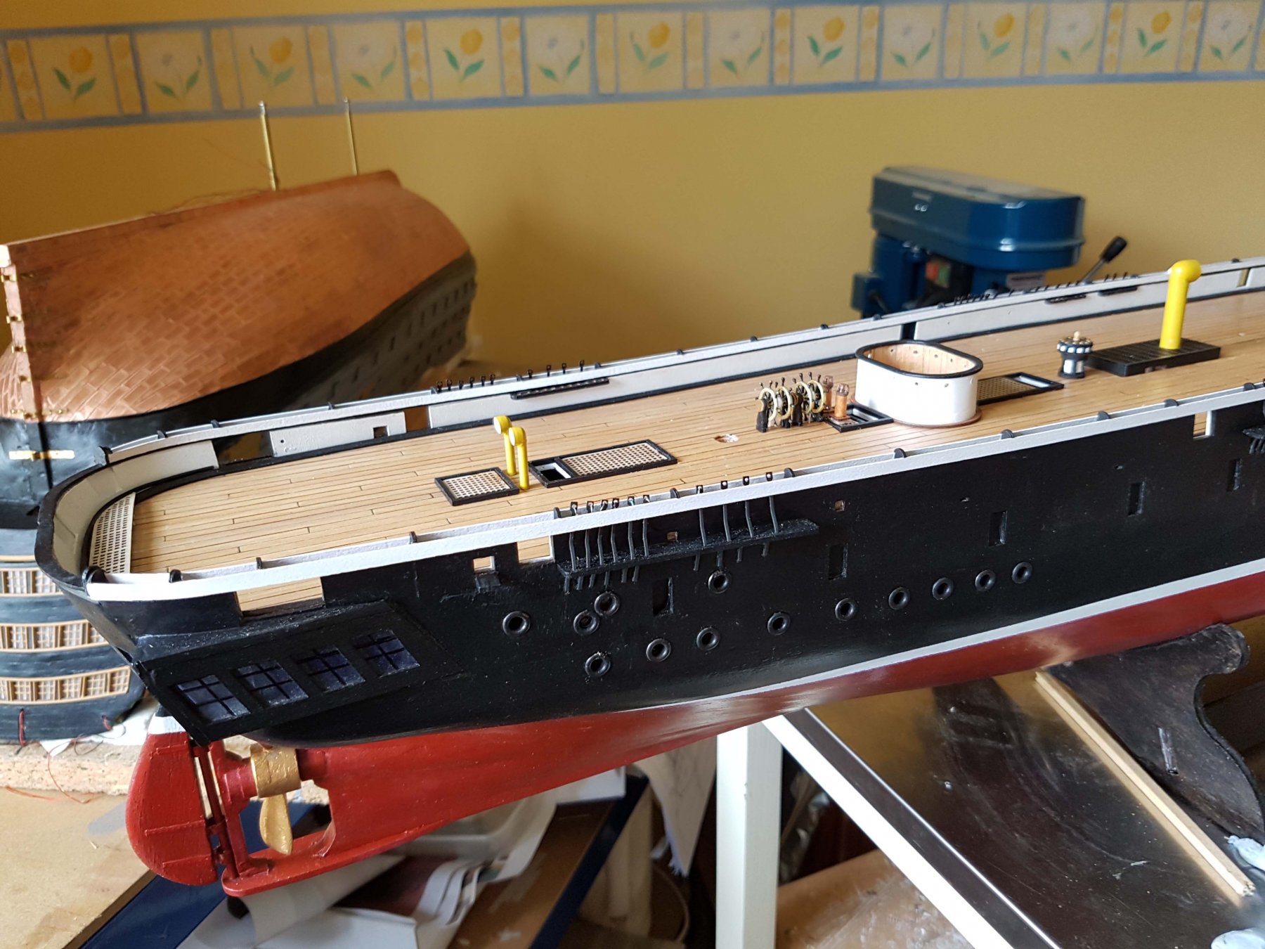
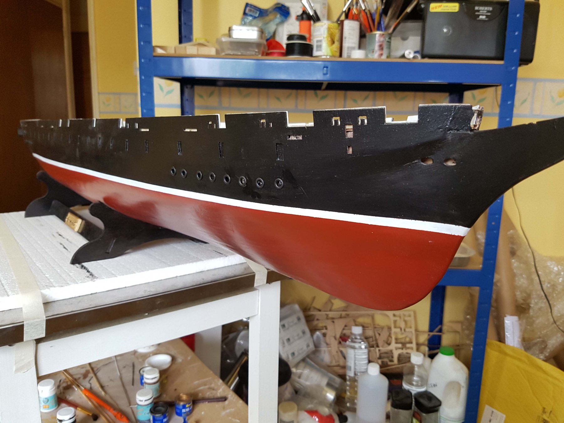
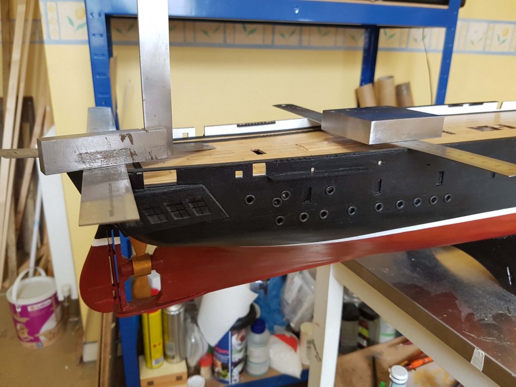
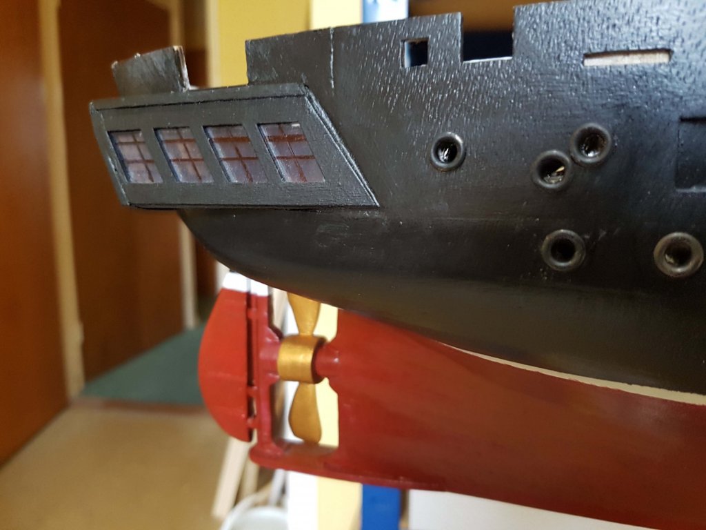
Hi All, Internal gunwales and deck channels added ... Propeller and rudder completed. I modified the hinge of the latter using 5mm brass tube fashioned into faux hinges with the horizontal supports cut from .5mm plasticard and run over with a pounce wheel to simulate rivets. The porthole surrounds are 4mm eyelets painted gunmetal and glued in. And a couple of general views showing the paintwork.


-
Janet, I used superglue when coppering the hull of my Victory, and yes I primed it first to prevent absorption ... still firmly adhering after a year Hope that helps. Philip
-
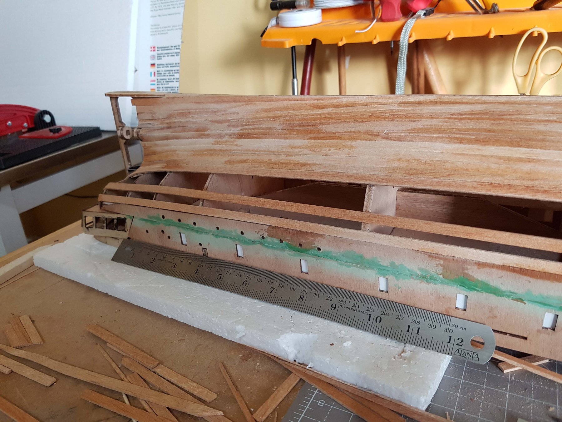
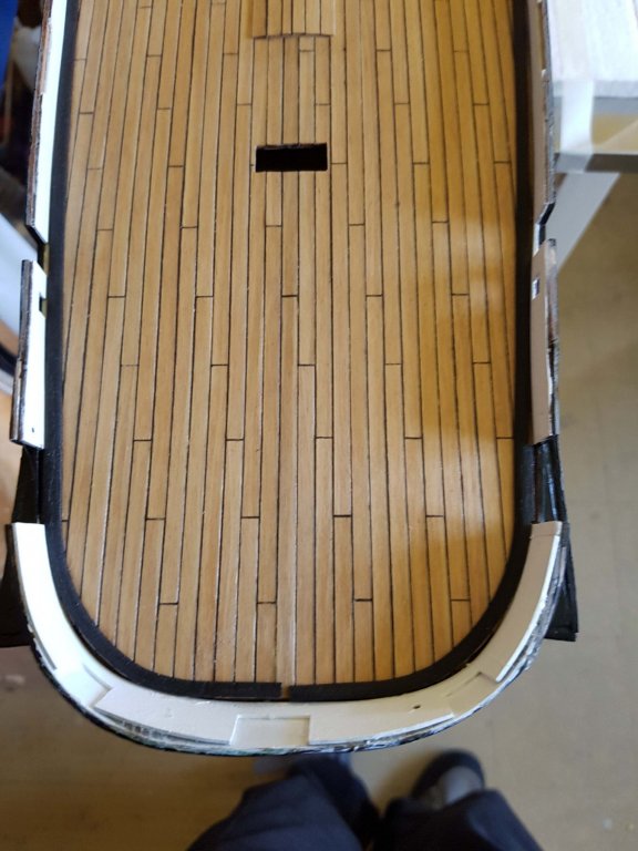
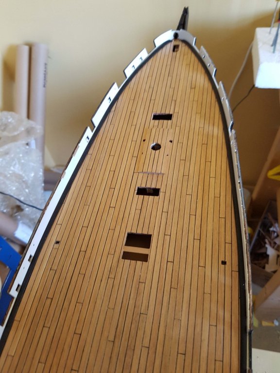
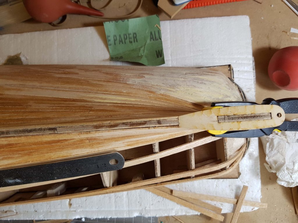
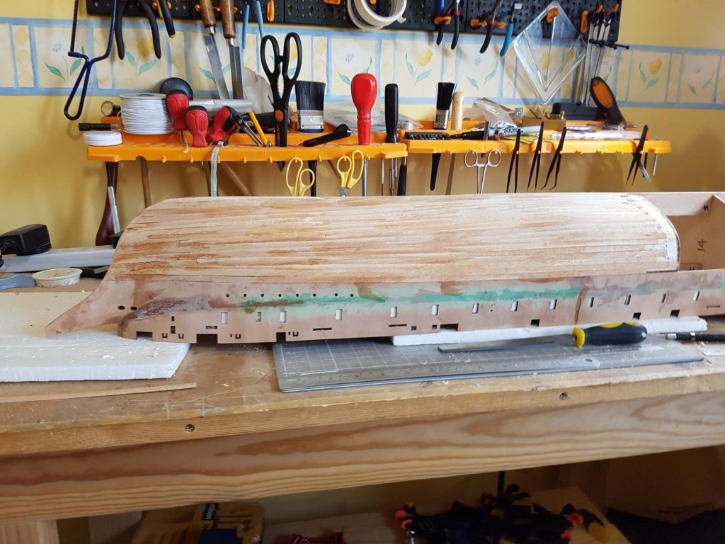
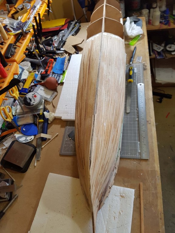
Planking complete, phew, as the late Cilla Black might say "That's a lorra lorra planks! Trickiest part is around the propeller well (which will be trimmed back flush) so apologies for the filler.


-
Welcome along Pat, or should that be aboard Hope you find some useful stuff for your build as things progress. Cheers, Philip
-
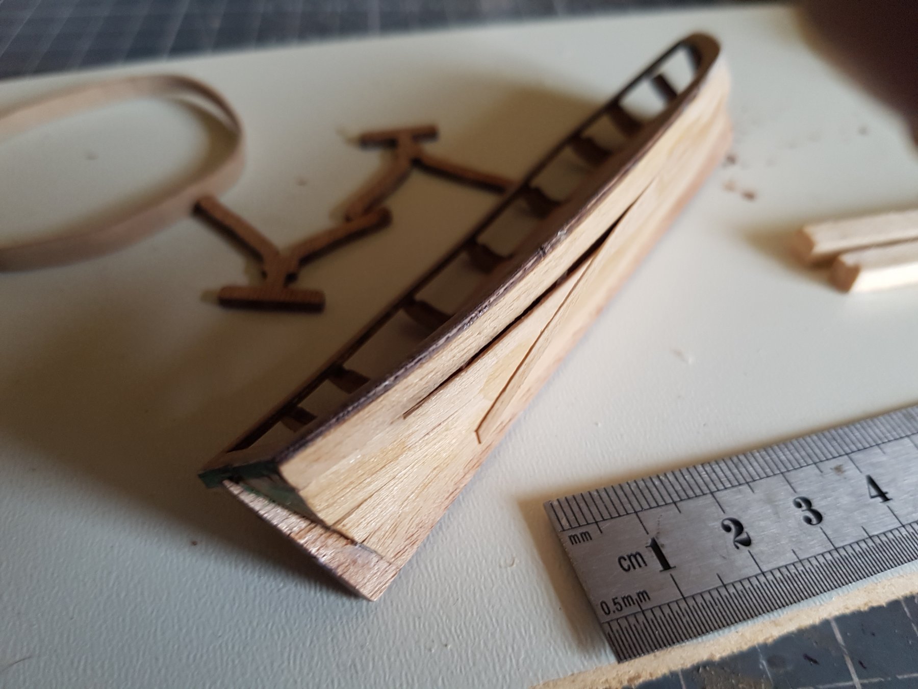
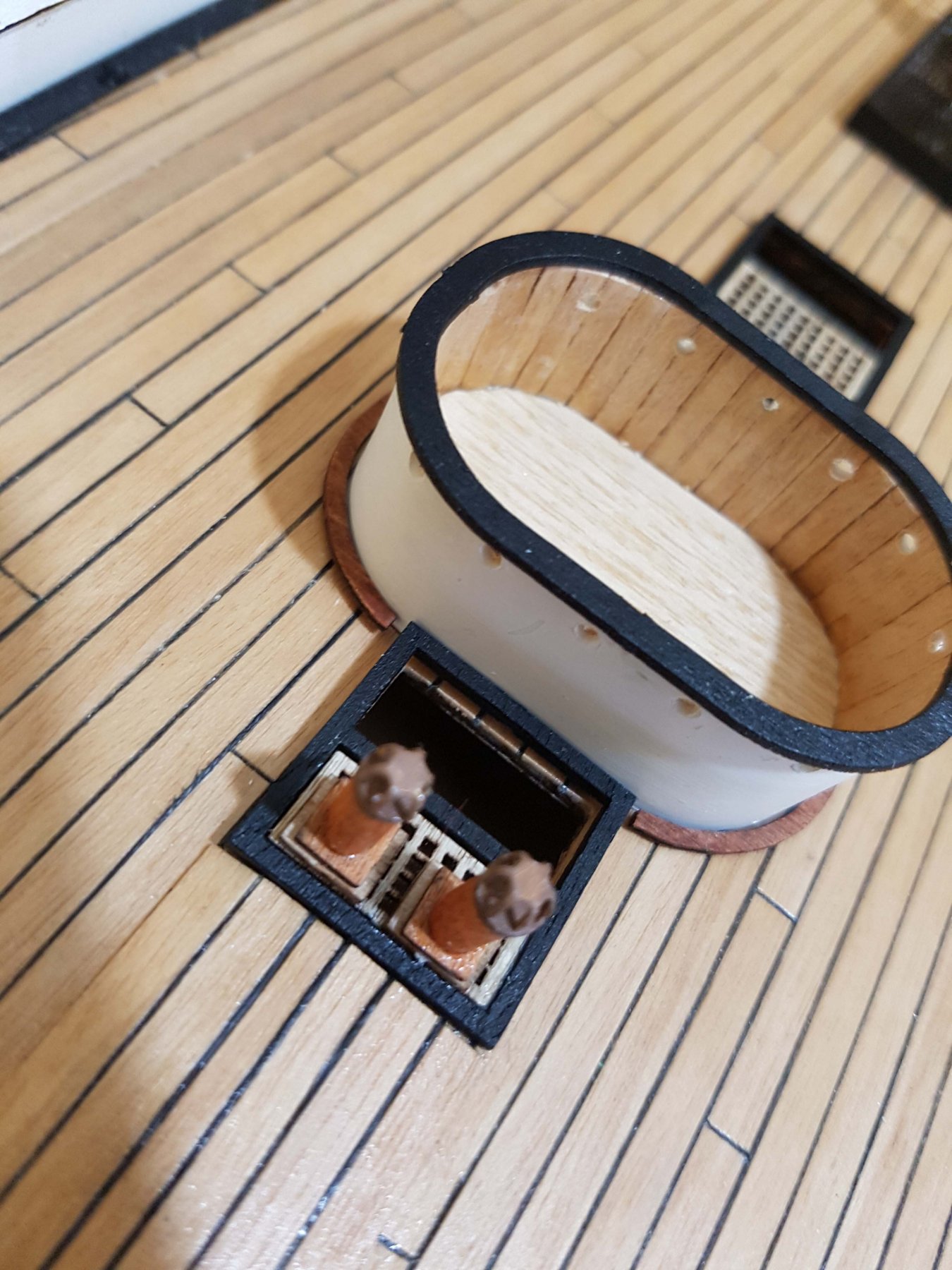
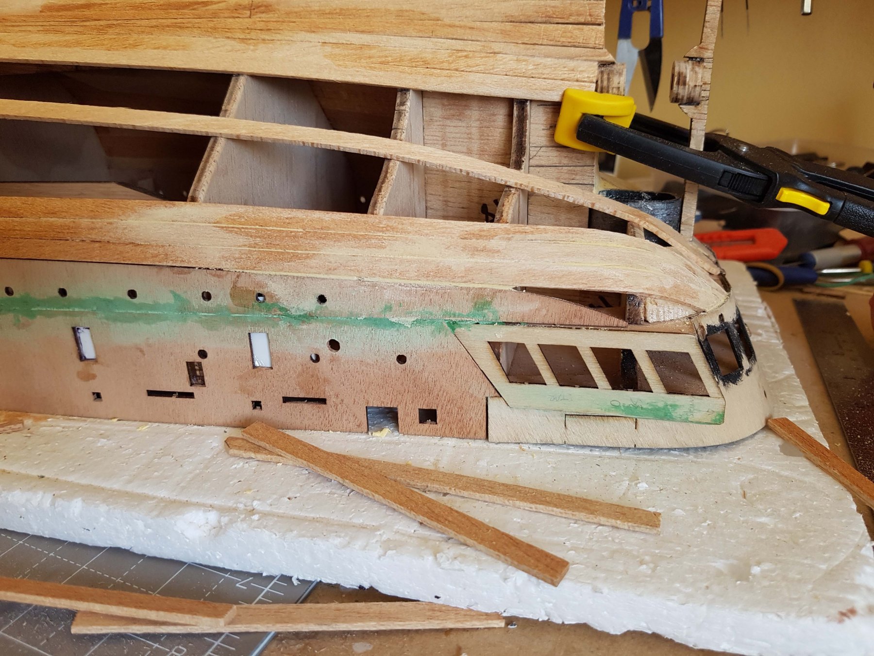
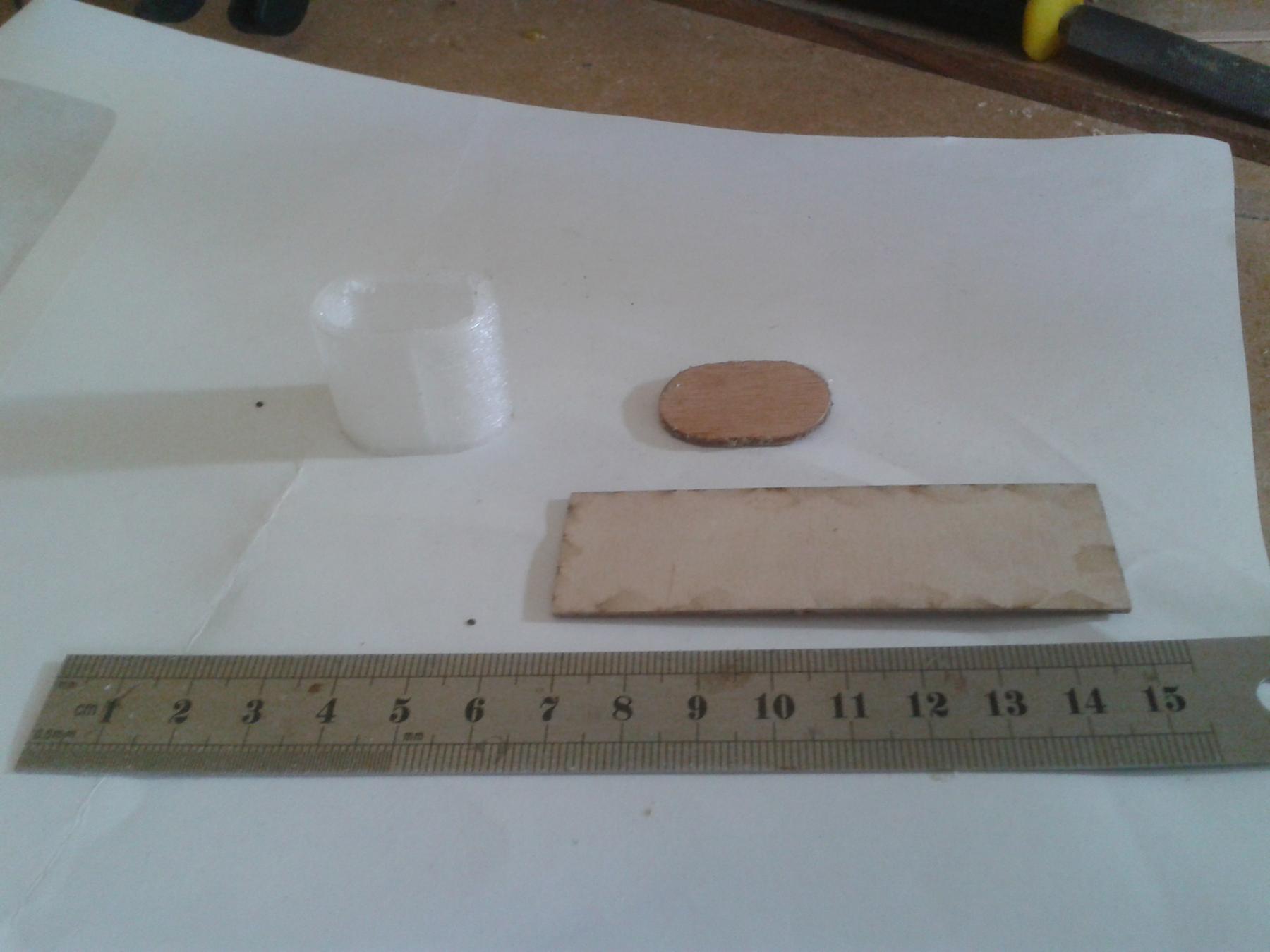
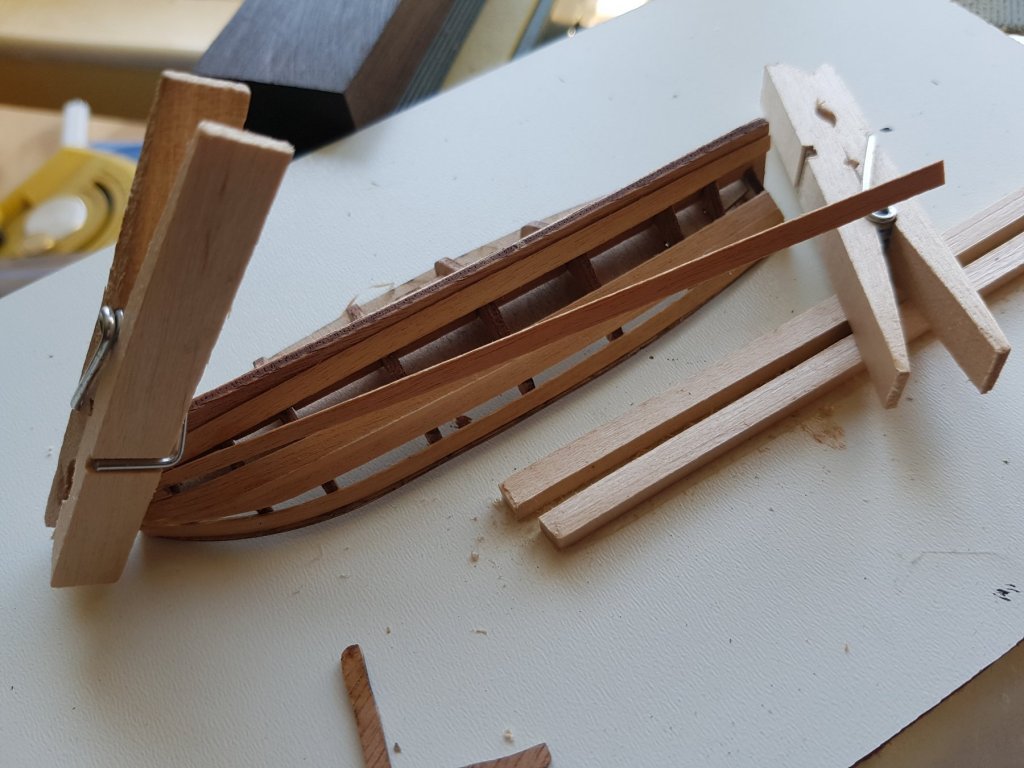
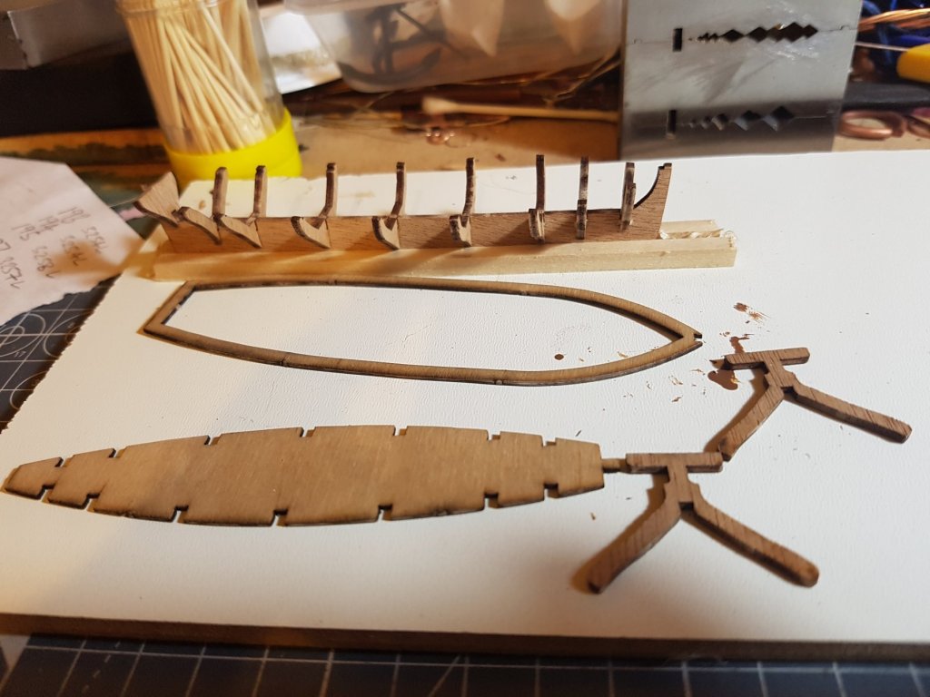
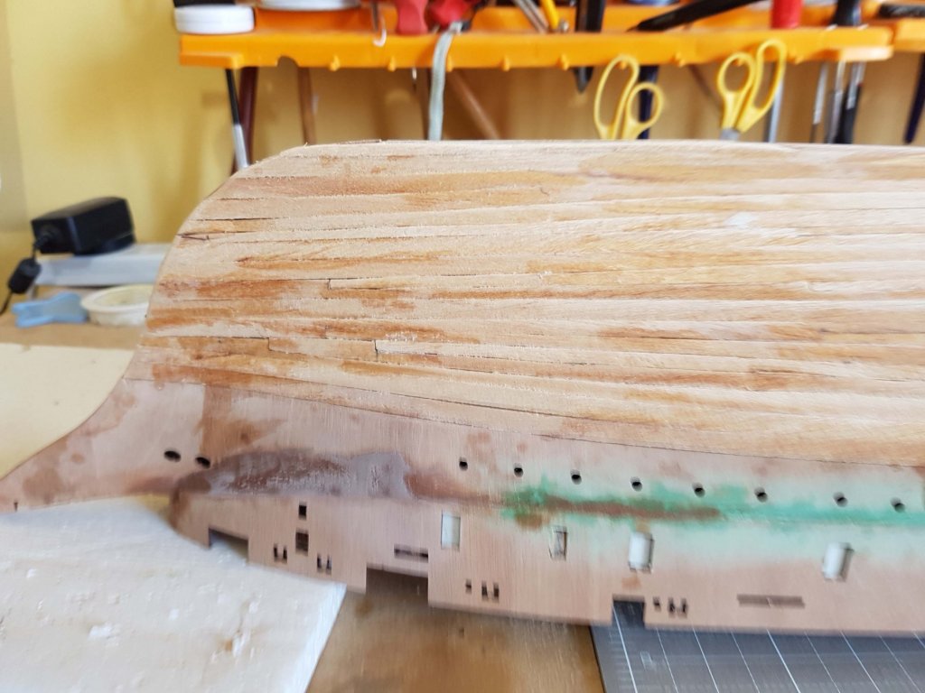
Half the planking fitted. After all these years I think I've finally got the hang of using stealers! The detail of the propeller well shows the 3D printed part
-
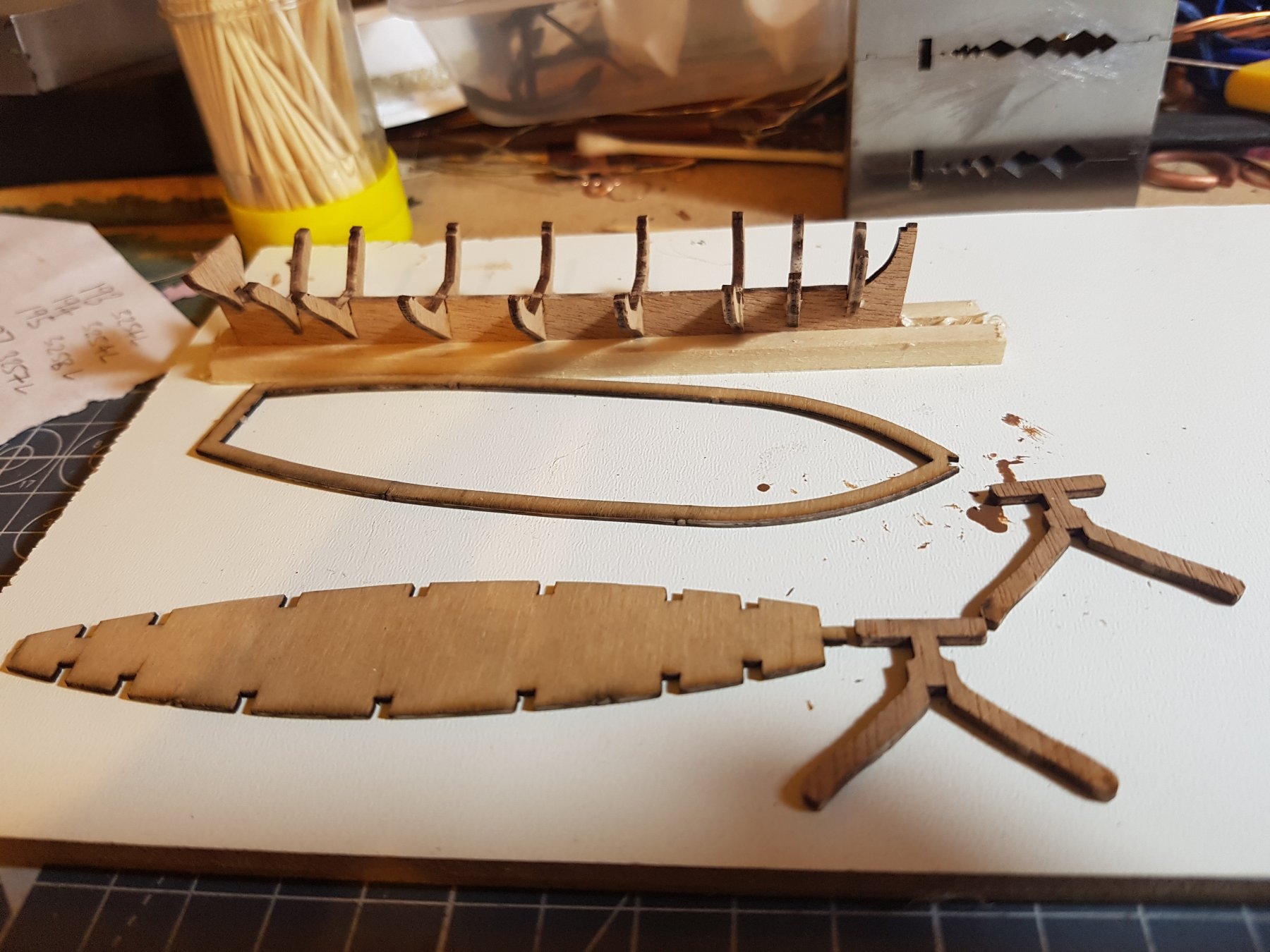
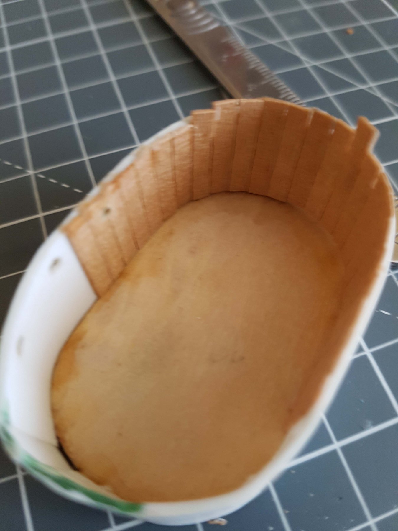
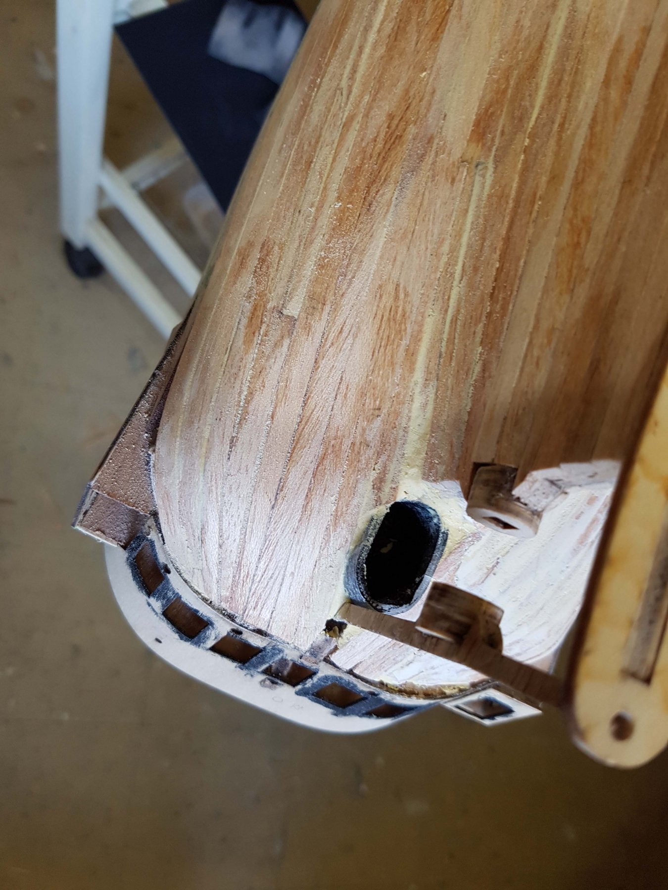
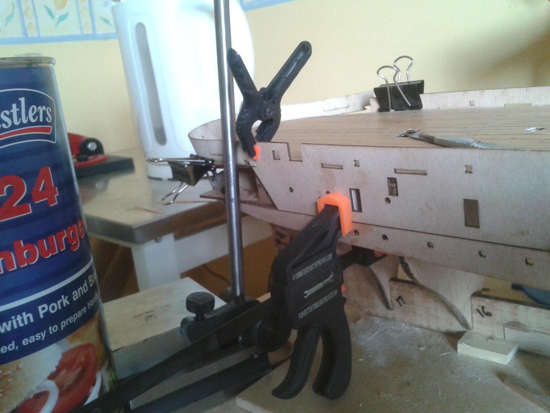
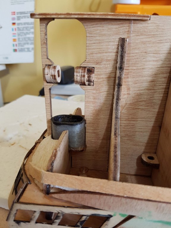
All the bulwarks are now in place - some convoluted gluing required! For the propeller well (whence the prop was pulled up into [manually!] when the ship was preparing to move under sail), Billing seem to think that it's possible to bend a 2mm piece of ply into an elipse without damage/delamination. I don't concur so I designed and printed one in ABS instead. Once it's painted black and buried under the stern no one will be any the wiser and it will hold the keel planks nicely.


-
Sorry for the delayed reply Gerhard but I missed your post. As far as plans are concerned I have failed to track anything down beyond the two books mentioned at the start of this log and another small booklet called Warrior: The first modern battleship by Walter Brownlee ISBN 0 521 27579 2. This has some good detail drawings while the other two both have rudimentary keel plans. The originals are in the National Maritime Museum based in Greenwich, London but they are not available online. Bear in mind that there were two major Warrior iterations: 1791 and 1860. Best, Philip