

CDR_Ret
-
Posts
658 -
Joined
-
Last visited
1 Follower

About CDR_Ret

- Birthday February 1
Recent Profile Visitors


-
 Admiral Rick reacted to a post in a topic:
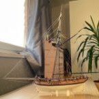
Novice builder and question re: Amati felucca
Admiral Rick reacted to a post in a topic:
Novice builder and question re: Amati felucca
-

Novice builder and question re: Amati felucca
CDR_Ret replied to jrbm's topic in New member Introductions
I'm not familiar with this vessel type. However, a weblink to a Facebook page provides 17 photos of these boats from San Francisco Bay and all of them show smoothly-fared bows into a stem piece. I'd say that flat-faced bow is incorrect. Terry -
CDR_Ret reacted to a post in a topic:
Novice builder and question re: Amati felucca
-
 Snug Harbor Johnny reacted to a post in a topic:
In which offense is taken (or, "hey! I resemble that remark")
Snug Harbor Johnny reacted to a post in a topic:
In which offense is taken (or, "hey! I resemble that remark")
-
Keith Black reacted to a post in a topic:
In which offense is taken (or, "hey! I resemble that remark")
-
In which offense is taken (or, "hey! I resemble that remark")
CDR_Ret replied to Cena's topic in New member Introductions
Like several others here, I built both Revell kits of the Constitution and the Cutty Sark when I was a mid-teen back in the '60s. Sadly, my father was still working for Link Aviation maintaining flight simulators at various air force bases around the US, so we tended to move around a lot. Poor planning on my part. The Constitution model got busted up on the move from Vermont to Ohio, and the Cutty Sark got busted up in the move from Ohio back to Vermont! I watched as the packer for the second move grabbed the ship by the bowsprit and lowered it into a bunch of wadded up paper for packing in the cardboard moving box. There wasn't much left at the other end . . . -
CDR_Ret reacted to a post in a topic:
Ramble Intro
-
It might be helpful to provide a link to the relevant article in the OP of this topic. I'm not sure where to find it myself, never having created a build log!🤔
-
CDR_Ret reacted to a post in a topic:
Please Double-Check Your Log Titles Before Posting!
-
CDR_Ret reacted to a post in a topic:
Nate's PANDORA in 3D
-
Heh, you can never trust submarine movies for dialog or technical accuracy. My family groans anytime we watched a submarine movie because I was always muttering, "That's not the way they do that," "that can't happen," or "that's an attack boat, not a boomer," etc. @CCClarke Terry
-
CDR_Ret reacted to a post in a topic:
HMCSS Victoria 1855 by BANYAN - 1:72
-
 BANYAN reacted to a post in a topic:
HMCSS Victoria 1855 by BANYAN - 1:72
BANYAN reacted to a post in a topic:
HMCSS Victoria 1855 by BANYAN - 1:72
-
Keith Black reacted to a post in a topic:
HMCSS Victoria 1855 by BANYAN - 1:72
-
HMCSS Victoria 1855 by BANYAN - 1:72
CDR_Ret replied to BANYAN's topic in - Build logs for subjects built 1851 - 1900
Good news, Pat. I was wondering whether something had come up. Very glad that you received a clean bill of health. Don't push your recovery. The model will be there. Terry- 1,013 replies
-
- 2
-
-
-
- gun dispatch vessel
- victoria
- (and 2 more)
-
CDR_Ret reacted to a post in a topic:
HMS Triton Project No Longer Available?
-
Starting in Rhino 8
CDR_Ret replied to GioMun's topic in CAD and 3D Modelling/Drafting Plans with Software
Not to mention that you actually have a head on your shoulders . . . ! -
CDR_Ret reacted to a post in a topic:
Starting in Rhino 8
-
hollowneck reacted to a post in a topic:
"Wind of the ball" injuries.
-
I suspect that, rather than a "vacuum" causing the injury, it was the peak differential pressure of the shock wave caused by the ball's passage on soft tissues. The turbulent, low-pressure region associated with a high-speed projectile is directly behind the ball, so the "vacuum" itself would have little to do with causing the non-contact injury IMO.
-
Nate's PANDORA in 3D
CDR_Ret replied to 3DShipWright's topic in CAD and 3D Modelling/Drafting Plans with Software
Hey, Nate (@3DShipWright) and @Loracs. I got the alert that you had tagged me. There are three things to address in such a tutorial: The key steps required in constructing a ship hull and its details. Ship's hulls are not the simplest thing to build in Blender, requiring a lot of knowledge of what you are trying to model first, then translating that into building it in a digital 3D space, which leads to: Knowing how to use the gazillions of features to actually form the model in Blender, and then adding the really cool textures and materials that turn it into a photorealistic product. And (3), placing that model into a photorealistic environment. Sadly, this isn't like a cookbook, where you can start with nothing and end up with something in a linear fashion. The Blender knowledge space is like a 3D network itself, with nodes of prerequisite information connecting to other information. That's about the only way I can explain it. Also, the way you create an object can affect how to enhance it down the road I think it would worthwhile to attempt such a general tutorial for ship modelers, since it is pretty evident there is an interest for a segment of our community in creating such a guide. It would take a lot of effort on the parts of one or two people. If we could crowd source the project (with, perhaps a knowledgeable editor overseeing everything), that could make it more doable. (I did that in DELFTship a while back.) The downside to attempting such a tutorial is that Blender is updated frequently enough, it could make at least the details of using the program out of date fairly quickly. That's my two cents (American). Oh, wait, we aren't making pennies anymore . . . Terry -
Tapering Masts and Arms the easy way
CDR_Ret replied to Johnny Mike's topic in Masting, rigging and sails
Regarding mast tapers (and this applies to spars as well), applying the tables found in Underhill's book for the latter 1800s, you can see in this image that the individual masts are not "conical" tapers. They tend to gradually taper starting at the base then more quickly toward the heads. This is because the torque applied to any section of the mast is greater toward the base and least at the head. That torque on a mast also includes the forces applied by the mast(s) above it. So it makes sense that the mast diameter doesn't simply change proportionately with height. An extreme foreshortened view of the 1891 brigantine Galilee's combined fore topgallant-royal mast, showing the mast taper profiles for each section. Terry
-
That was true as well in our operational spaces on a submarine. Cupholders were provided near any flat surfaces. However, in the Wardroom and Crew's Mess at sea, tables were covered with Naugahyde, which was somewhat padded, so plates and cups didn't slide with rolls, and angles and dangles. Terry
- 489 replies
-
- 3
-
-
- minesweeper
- Cape
- (and 1 more)
-
Importing files into Delftship
CDR_Ret replied to woodartist's topic in CAD and 3D Modelling/Drafting Plans with Software
Hey, Julie, I think those are the files for my Background Images tutorial that I created back in 2022 when I was still primarily using DELFTship. The files can be found here in MSW. You are correct that the instructions are a bit dated, but the principles are still pretty much the same. Those instructions were created with reference to DELFTship v. 19.10 (328). The current program version is 17.30 (358). (Don't ask me how the version numbering system works . . .) The instructions are best for providing the steps for approaching a project. The D/S manual is and has been very weak on how to get into constructing a model. It tells you what each feature does, but very little on processes. Terry -
Starting in Rhino 8
CDR_Ret replied to GioMun's topic in CAD and 3D Modelling/Drafting Plans with Software
Hi, Giorgio. I'm with Julie on this topic. It's likely that someone proficient in Rhino would be able to eventually develop a nice hull, and then add on all the topside embellishments. However, trying to learn how to use a general-purpose 3D-CAD program like Rhino to create a hull comprised of surfaces varying in three dimensions, adhering to an existing set of basic plans, has proven to be challenging to a lot of folks attempting that. DELFTship, on the other hand, is a for-the-purpose naval architectural program with built-in features, like the three standard hull form views (sheer, halfbreadth, and body plans), along with features like "intersection" lines to show stations, waterlines, buttock lines, and diagonals—that all help in hull faring process. This is almost always needed because classic vessels were constructed from hand-drawn plans, and these plans, especially if they were developed before the advent of CAD, tend to lead to lack of fidelity among the standard views. In addition, DELFTship provides surface analysis tools that enhance the faring process, like Gaussian surfaces, that visually reveal bumps in the hull surface as well as providing local curvature analyses. The program is primarily used for hydrostatic and hydrodynamic analyses, but the structural features work well for simply modeling at any scale. One difficulty that most new DELFTship users have is what Julie mentioned—the surface mesh (called the control net) doesn't actually lie on a curved surface because of the mathematical way the program works, which is something you simply have to get used to. I suggest that you take a look at some of the reconstruction projects here in the various forums that utilized DELFTship to see how it presents. Like most 3D modeling programs, it has its own steep learning curve, but once you become familiar with it, the results are directly useful for developing plans of a vessel hull. Terry -
Late 19th or Early 20th Century Running Rigging
CDR_Ret replied to GrandpaPhil's topic in Masting, rigging and sails
Here's my two cents: My Galilee was an 1890s-vintage US-West Coast brigantine. As-built, her standing rigging was steel cable. For the DTM charter (1905--1908), her mast standing rigging was swapped for arctic-service hemp rope to reduce her magnetic signature. Photos of her prior-to and early into her DTM charter period showed rope running rigging throughout except for light chain sheets for the jibs. The foremast yard tye-lifts were of heavier chain, which were retained even during the DTM charter period. Some of the heavier service running rigging for the main boom, like pendants and lifts, may have been wire. Hard to tell from the photos. Hope this helps. Terry -
This is a recent BBC article about the Sutton Hoo ship, including a site photo.