HOLIDAY DONATION DRIVE - SUPPORT MSW - DO YOUR PART TO KEEP THIS GREAT FORUM GOING! (Only 13 donations so far - C'mon guys!)
×


BenF89
-
Posts
316 -
Joined
-
Last visited
Content Type
Profiles
Forums
Gallery
Events
Everything posted by BenF89
-
 Hi Denis, No - not permanent yet; using it as a temporary to ensure the other bulkhead templates remain square. I'll be able to re-fair the curve of this bulkhead, and trust my gut on the other templates. But - yeah, if it was permanent I'd use a gap filling glue or putty or something (assuming it would even be visible once the deck and furnishings were built in). And, yes - I'm happy to be making progress, too. Fits and starts with this, given work and three kids 5 and under... trying to make as much progress as I can before it gets hard again (whenever that may be)
 -
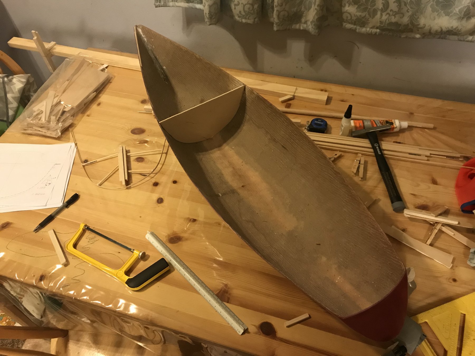
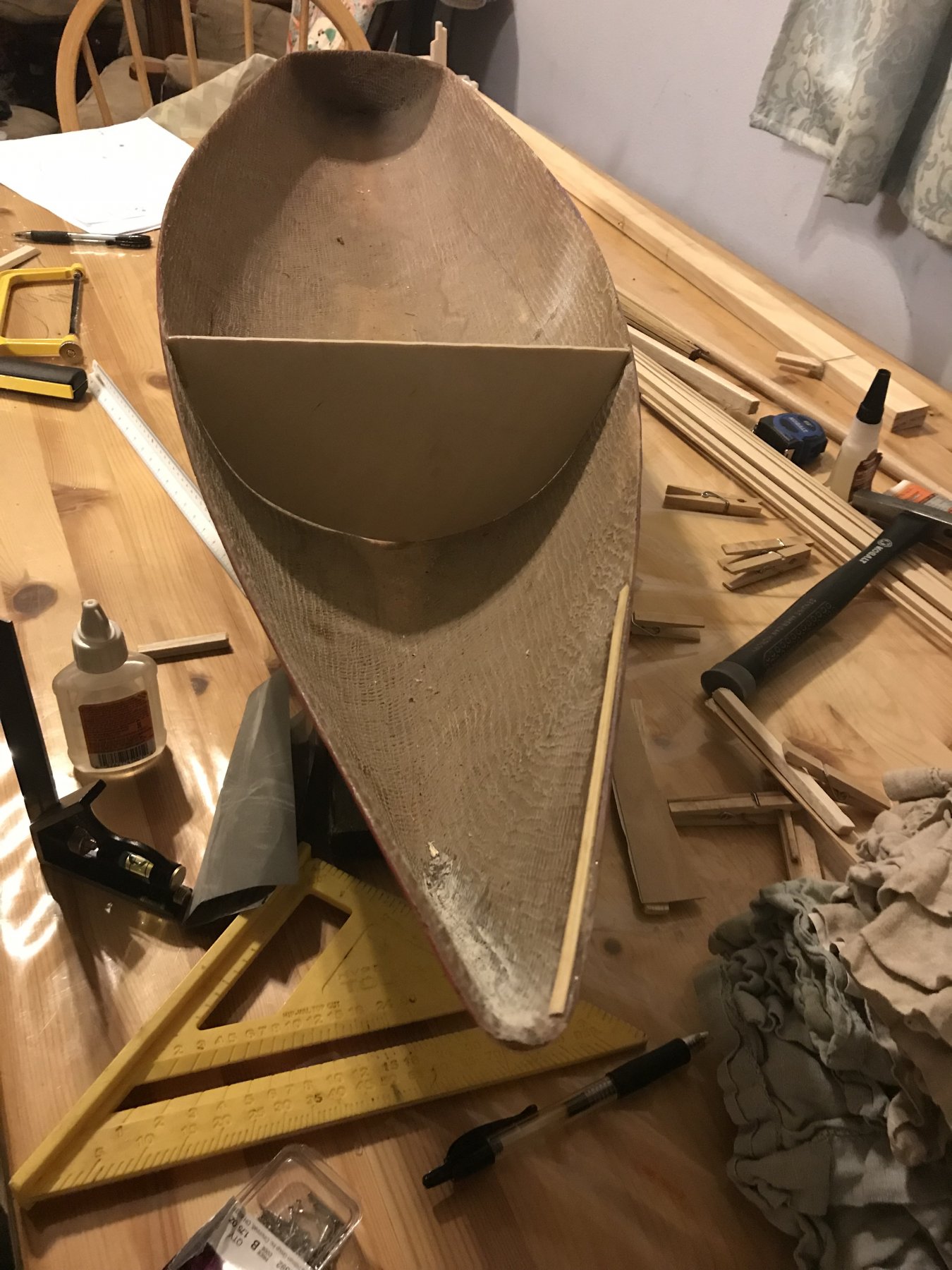
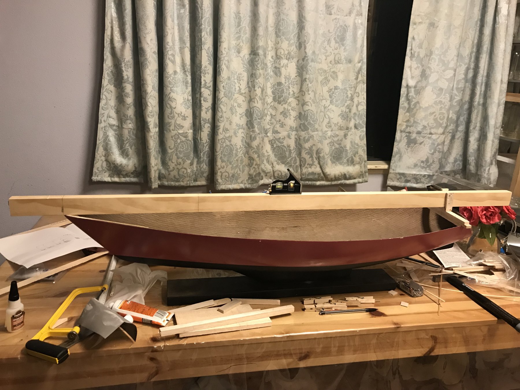
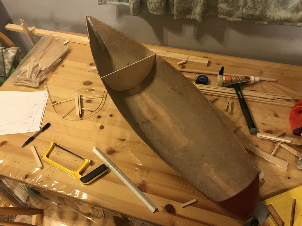
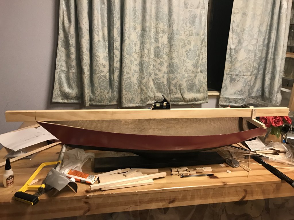
TEMPORARY 'DATUM' BULKHEAD INSTALLED I used the template from the boat to trace out a first, temporary version of the 'datum' bulkhead onto a small sheet of 1/8" modeling plywood. Then I 'tacked' it in with superglue at the gunwale port and starboard and at the keel. It's solidly in place, but should also be fairly easy to remove when it's time to replace it with the real bulkhead. First (Temporary) Bulkhead In Place The purpose for the temporary is to use it as a better means of getting measurements to the remaining bulkheads without having to rely on trigonometry or other head scratching to locate and keep square the other bulkheads. With the temporary in place, I can take solid measurements at any point along the beam to get a couple points on a straight line parallel to the bulkhead, so everything stays square to everything else. I had to make it temporary, because (1) I don't want the real bulkhead ruined for whatever reason while I finish up the remaining six bulkhead templates, and (2) if I made the full bulkhead, including the shape of the overhead, it wouldn't fit under the longitudinal beam jig thing. And, my parenthetical comment at the very end of the last post about the template not quite capturing the fullness of the shape on one side was right - you can see where the light shines through in the picture below. There's a small gap between the bulkhead and shell. 'Fit Check' of Temporary Bulkhead I can re-fair and fix that when I cut the real bulkhead, and I also now know to trust my gut instinct when it comes to an issue of questioning the template shape.

-
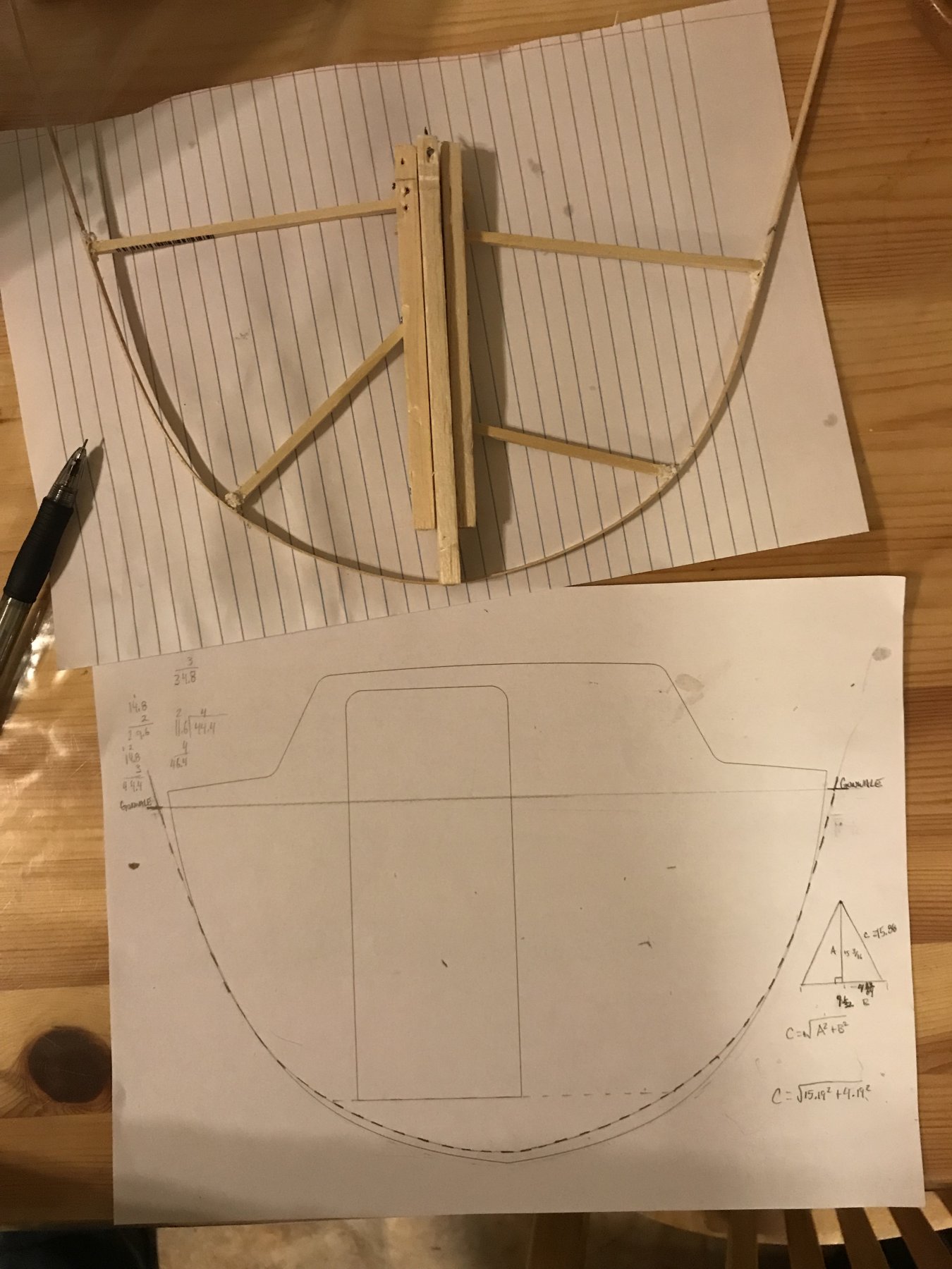
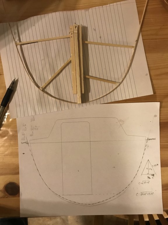
FIRST BULKHEAD TEMPLATE I had one more hiccup in the template process to sort out. I had used wood superglue to hold all the bracing to the vertical center post and to the strip of wood forming the template. It ended up not holding, and when I pulled the jig up the template was (a) not really attached to the bracing and (b) kind of attached to the boat. So it all pulled apart. I did a second attempt, this time with Gorilla Construction Glue, and re-clamped it overnight. I also slipped a strip of thin paper between the template and the hull, to prevent it being attached again for whatever reason. I tentatively pulled out the jig this morning, and it was all still held together and held shape well. I pulled the template off the longitudinal beam, and (with a little more pondering) figured out how to align the template with my 'predicted' shape. I matched the keel, then it was a little skewed, so, with the keel of the template at the keel of the pattern, I marked where the gunwale of the template was (I had marked the gunwale onto the template when it was in the boat). then I took a square and drew a horizontal line to the other side of the boat, then shifted the template so that the gunwale marks were horizontal. This took it off the keel, and made the shape slightly asymmetric. (Also interesting is that beam is a bit wider than in the pattern.) The comparison of the template shape (dashed line) and the pattern shape (printed solid line) is seen in the image below: Template of First Bulkhead I think the asymmetry/discrepancy is reasonable given the age and condition of the hull. Also, my pattern is based on the exterior, and my template is the shape of the interior, and there seems to be a lot of resin/glass buildup within the hull in way of the ballast keel below which might cause the discrepancy in shape I'm seeing. In the end, it doesn't matter that it's asymmetrical and different since all I actually care about is that I have the actual shape of the inside of the hull. (Of course, it could be that the template is wonky and didn't capture the fullness of shape on one side, in which case.... wood putty or something could fill any gaps not hidden behind joinery or below the deck, I suppose.)
-
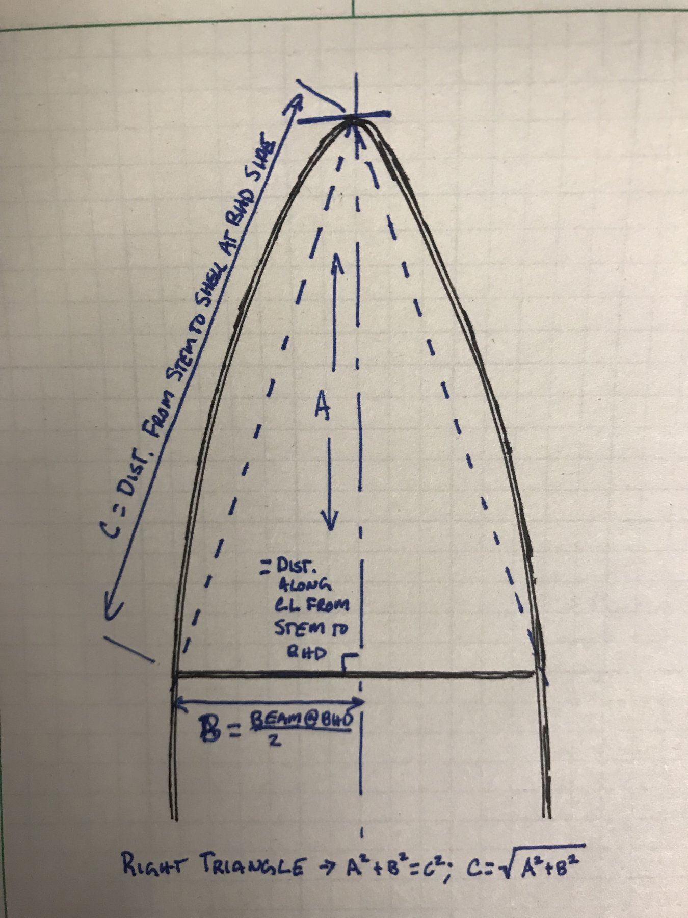
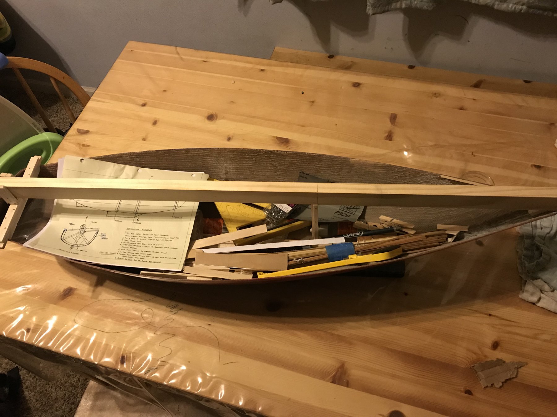
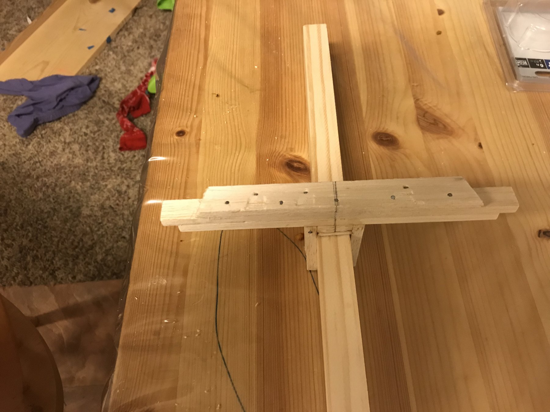
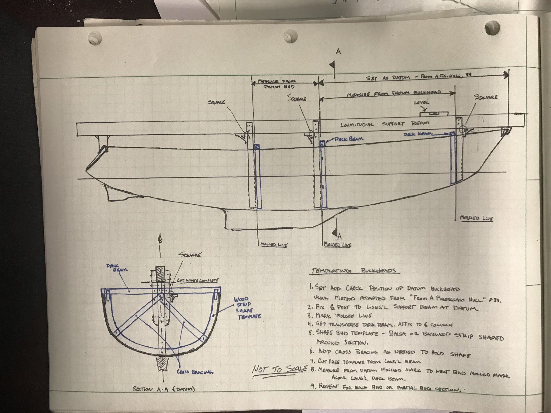
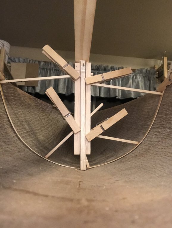
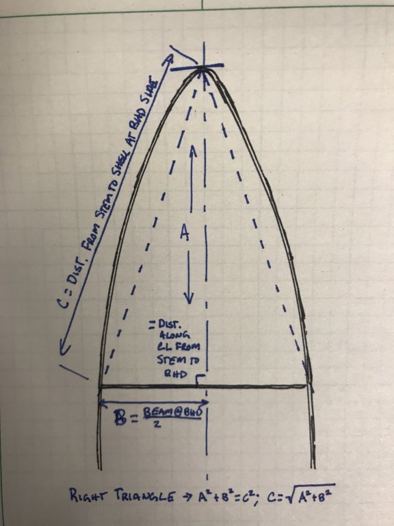
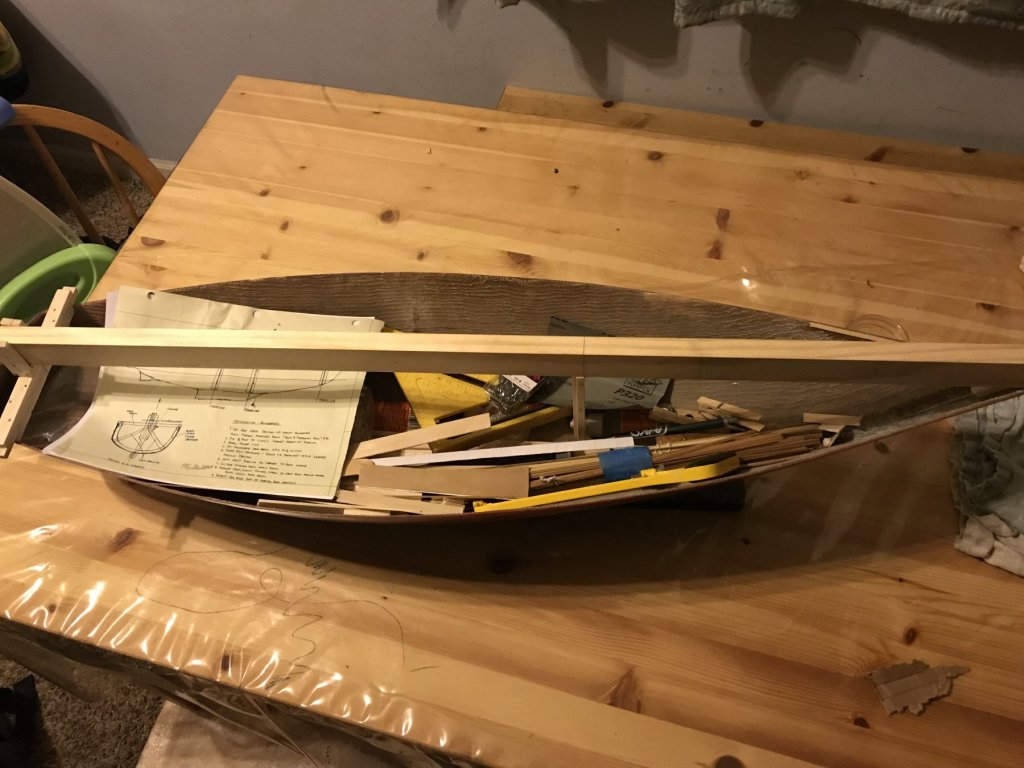
Thanks, Patrick! It's slow going (but then, so has this whole project), but I have a feeling that all the groundwork will help it fly together once the parts get cut. If I can set the bulkheads and lay in the interior deck, then the joinery work should all be pretty well set, and I can adjust parts as needed based on actual measurements in the boat. Like on a real boat! It's often a wonder to me how the scale often has little effect on the overall methods of model building - in the end, building a boat is building a boat - materials and tools are different, but in broad sweeps (and often in details) model boat building looks a lot like boat building. BULKHEAD TEMPLATING JIG - PART 2 So, another small update. After a lot of trial and error, I think I figured out how to make this template thing work. I started by adding a vertical post/support with the forward end of the support at the 'molded' line for the bulkhead: 'Datum' Bulkhead Vertical Support I did my best to keep it square, but it's a super big pain in the [insert preferred synonym for lower rear abdominal region here]. So it's mostly square. But, that's mostly ok. Because the methodology I'm using from my book also prescribes marking out the distance from stem to the shell at the side of the bulkhead. Which I just noticed is super confusing in words. Here's a picture: MATH! So, using that method, I can ensure the bulkhead template is square by lining it up with the marks on the shell. Again, mostly. Some good eye-gauge judgement was required, and everything was tweaked and adjusted until it looked and 'felt' square, since there is not really a good way of ensuring/checking it with an actual square. Also, it's just a template at this point, and I'll come up with a way to make sure the bulkhead itself is fit truly square. Which I can't do until I have a good shape to cut to, hence the less than perfect but good enough for it's purpose approach to the template. I'm finding that, surprisingly, modeling is helping me overcome my perfectionistic tendencies and be ok (and, actually happy) with 'good.' Ok - so, then came the REAL trial and error. I tried several attempts with multiple different materials to run a shape around the hull and fix it in place. I finally found that the best combination was (1) some 1/32 x 3/16 basswood strips 24 inches long for the template shape, braced by 1/8 x 1/8 basswood square strips, and (2) holding the assembly and place with all the wood superglue and clothespins (which, I notice upon writing, aren't pins. Words are weird). Even this was a process - I found that I need to use a clothespin at each side of the beam to first fold the darn thing in place, then ease it into the exact shape of the hull, and then systematically apply braces and superglue and clothespins to fix it all in place: First Bulkhead Template Assembly So that's where I'm at now - I'd hoped to be further, but I was sick all day Saturday and went to bed early rather than try to exert mental energy. I'm letting all the glue cure today, so that (hopefully) it's all rigidly connected and won't shift shape. Although, looking at the picture, it seems I have too large a span on the port side. Might have to brace that section first. P.S. Having a large hull makes convenient temporary storage of tools and supplies in a way that when the boat's put up, they're out of sight:

-
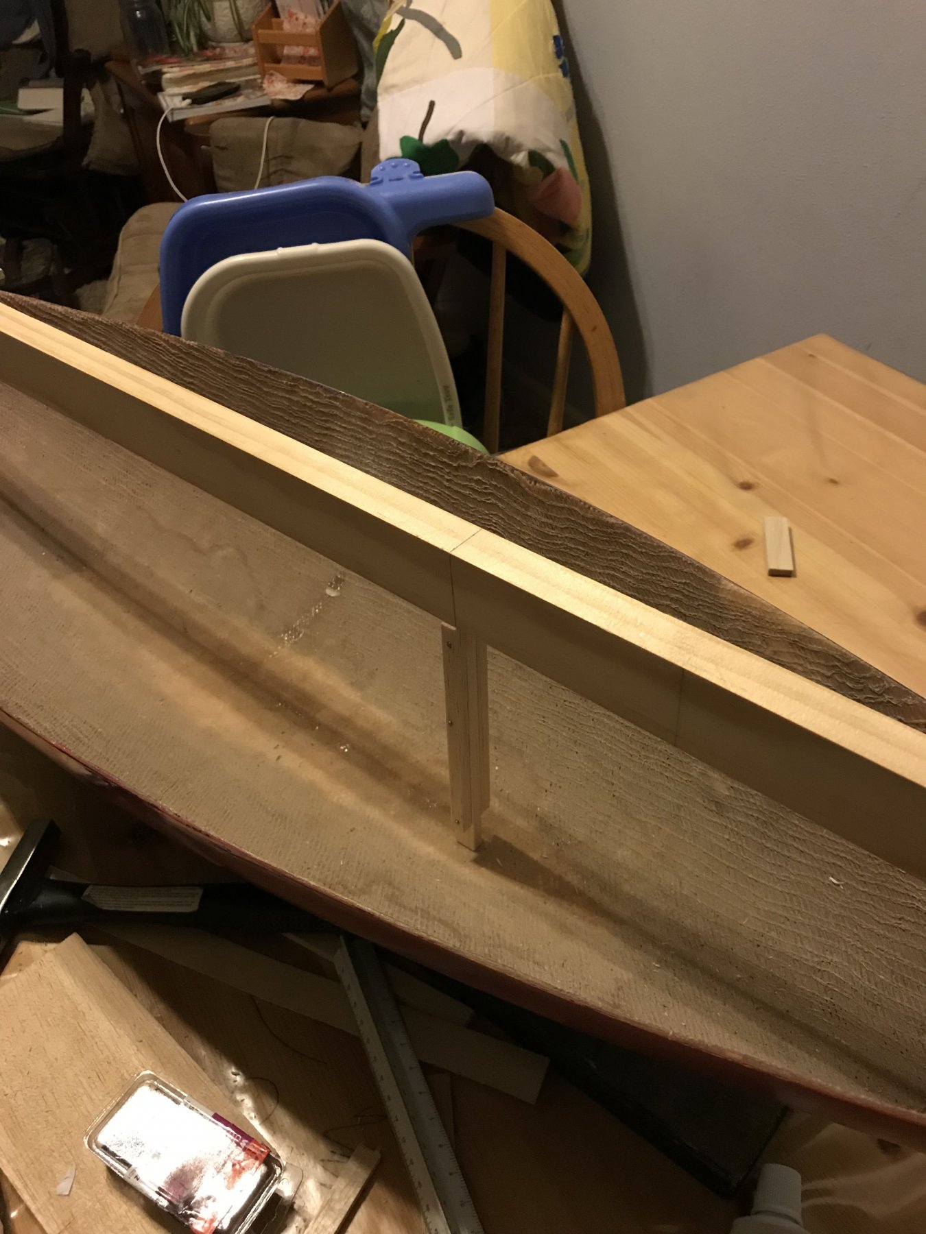
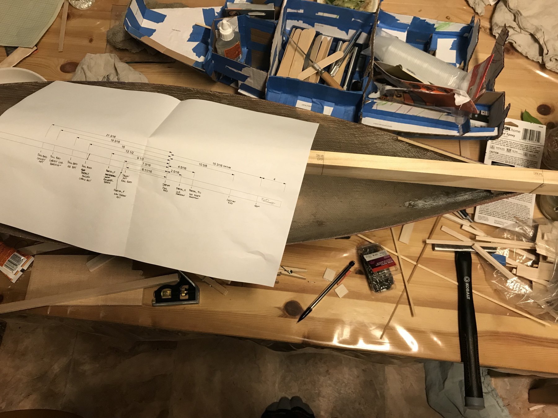
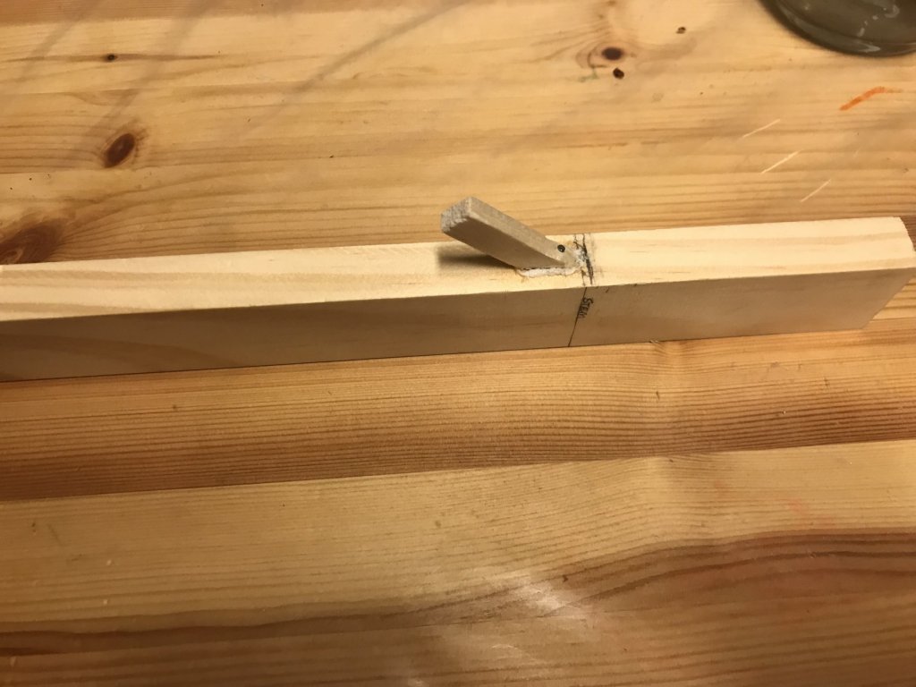
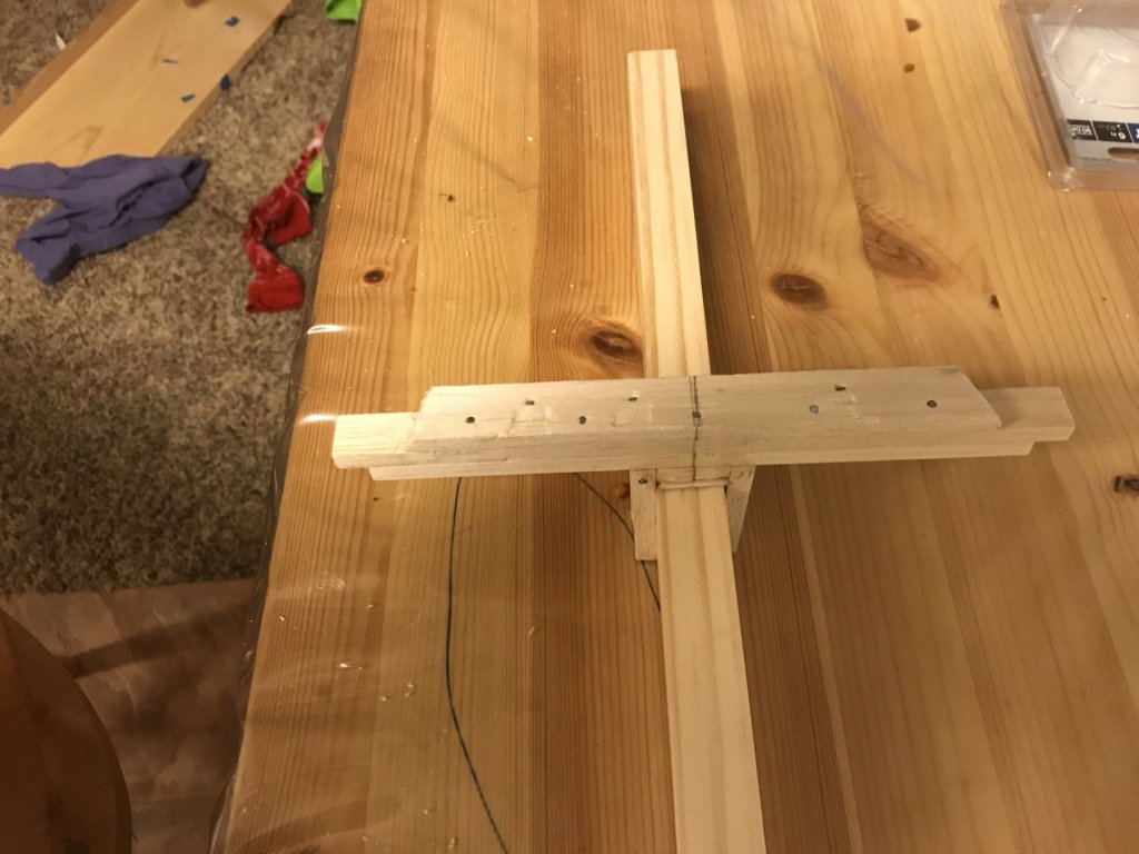
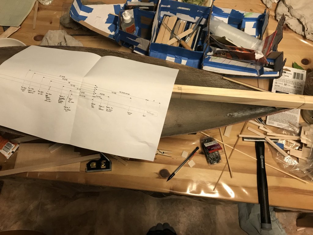
BULKHEAD TEMPLATING JIG - PART 1 I've built the main longitudinal beam of my template jig I sketched up and shared on Monday. I got some nicely finished, and straight 1x2 pine from the hardware store. It cost about twice that of the normal 1x2 furring strips you get, but double a little over a dollar is a little more over two dollars, which seemed justifiable given that the furring strip was not as straight as what I got. The next steps were (a) identify the dimensions to the various bulkheads and partitions to mark out along the beam, and (b) figure out a way to put it on the boat such that it's easily removed, but when put back is in the same place (so my templates are taken at the right place relative to the other templates). The first part was accomplished by using my design 3d model to ID every transverse section that touches the hull. There are a lot of them. More on that later. My solution to the second part was to first ID where I wanted the stem. So I marked that. Then I laid a small piece of balsa into the inside of the stem, and trimmed it horizontally so that when attached to the pine, it would set my mark at the stem and prevent movement forward. See the image below: Stem Guide/Chock/Thing Then, at the aft end, I had to do three things. The first was to prevent movement aft (which, combined with the stem guide/chock/thing preventing forward movement, would fix the beam in place longitudinally). The second was to make sure the beam ran down centerline of the boat, or close enough to it that my measurements stay correct. The third was to make sure the beam was level. I accomplished all three by building up several layers of balsa wood. The lowest was fit into the aft part of the hull, with the sides trimmed to the hull shape. Then I added a couple strips to build height (leveling the beam with the sheer line at the stem). Finally, for the last layer, I made a chunk the width of the beam, and then added guides to either side. Each successive strip of balsa was centered to the piece in the boat, so that the guides on the sides of the last chunk would make it so that the beam was centered. Again, see the below picture: Aft Beam Support - Levels, Centers, and Prevents Aft Movement. One thin balsa shim added to the last chunk put the level bubble dead center. I should note - I put the whole thing together with a hodge podge of wood superglue, Gorilla Construction Adhesive, and small hobby nails. The next picture shows the finished jig on the boat: Finished Longitudinal Beam for Bulkhead Templating With the longitudinal centerline beam complete, I started the process of marking out the template locations by marking the 'datum' bulkhead which will be used to double check all the other positions of the bulkheads, partitions, and interior joinery. I used the forward side of each partition or bulkhead as the 'molded line', so that the thickness is thrown aft, for consistency. A picture of the first bulkhead marked, and my previously mentioned bulkhead-and-partition measurement reference, are below. Bulkhead and Partition Measurements I have a lot of templates to make, it seems. Thinking about only templating those bulkheads and partitions that significantly interact with the side (vs only hit it for a short distance, especially if hidden behind something). Next update will (hopefully) be once I get the 'datum' bulkhead (which is the forward bulkhead of the main salon/aft bulkhead of the forward cabin) templated. I'm planning to print out each bulkhead or partition shape from the model, and compare with what I actually template on the boat. It will be interesting to see how close my process for measuring and adjusting the hull shape got me.
-
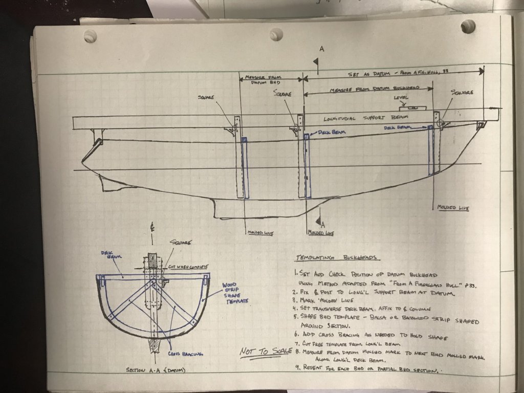
Follow up to previous post: I sketched up my 'jig' and the process I'm intending to follow. I'm thinking this may finally put the concerns I've had about section shape and proper fit to rest. We'll see. Either way, it's a learning experience for next time... (Note, some of the parts of the jig may seem overkill. Part is being not to scale, part is overengineering. I suspect some aspects will be greatly simplified in practice.)
-
I got to play with my scroll saw this weekend; I've got the feel for it, and figured out (I think) how to approach cutting the parts out so that I don't botch the part - by giving myself a line outside the 'finished' line that I can cut to and then sand or file down the rest. I'll try a couple parts this way and see if it works. I've also done some experiments with a couple different glues to figure out the process and glue type to adhere the wooden interior parts to the raw fiberglass interior. By sanding down to a mostly-smooth surface on the interior, I managed to use some clear Gorilla Glue to fasten a plank strip to the hull. The only problem is the clamping required; it won't even tack up for a long while after gluing, and I don't have a good way to clamp things like bulkheads. I've also got some 5-minute 2-part epoxy, so I want to try that and see how it works. Finally, I've been continuing to think about how to get the fit to the hull shape right. I'm still not entirely satisfied with my lines work, or the template process (I think they were great strides, and helped me get a more functional arrangement, so I don't regret those processes at all.) I've been reading up on how to build a real boat when you have just the fiberglass hull, and got a better idea for making a template of the bulkheads and partial bulkheads that will fit to the hull. I'd show it, but I need to work up something more than a napkin sketch for it to make sense to anyone (including me.) I've also rethought the build process - I was originally going to set the inside deck, and work from that as my 'datum', but reading up on the fitting out process for a home-built boat interior, it seems they set a datum bulkhead first, then use that to set the other bulkheads or partial bulkheads, put in the deck substructure, then lay the deck and finally do the joinery work. So. I think I'll do the same. It's more reasonable getting the template shape for the bulkhead sections than trying to template the shape of the deck (at least using the methodology in the book I've got). And, since many of the deck's edges are hidden, it's easier to get away with a less than perfect fit to the shell. And, it may allow the possibility of pre-fabbing some sections of the arrangement on that section's deck panel, and dropping the whole thing in as an assembly. Not sure that will help any; but it becomes an option for areas where have a secure 'base' to the joinery will help with the sub-assembly. More to follow after noodling a bit more on my jig/contraption thing for getting the bulkhead section templates.
-
Small Update: I got my scroll saw yesterday! Now I just need to learn how to use it... but I think that some real interior parts will be coming soon! Maybe! Shoot. I just realized I haven't figured out how to attach the pieces to the hull (wood to fiberglass). Probably an epoxy of some sort. I'll have to noodle on that a bit...
-
Hi Patrick, I'll see what I can find. I agree- hull plans are probably a no-go, even if he had them. But I might get a description that could be useful to you. If I get anything, I'll send it to you directly. And yes, I believe that Palmer Johnson is functionally out of business. I think owner might still be trying to sell stuff, but I'm 90% certain the yard is closed.
-
Hi Patrick - Just FYI: I work with someone who used to work at Palmer Johnson (the builder of Khalilah). I'm not sure he has (or can provide) any useful information, but I saw the yacht and was like "Oh! I know a guy..." Good luck! I'm excited to see this next one - I'm always impressed at the creativity in taking these challenging 'superyacht' shapes and making them look spot-on in such small scale.
-
INTERIOR CONSTRUCTION TEMPLATE - PART 2 So, it's been nearly a year that this boat has been sitting on the top shelf. Been a busy year - had a big US Navy proposal, followed by a transfer to a new location for work, then a third baby (a boy, born in August), and then another set of proposals and other work. Also (and, more significantly), I got to a point where I didn't have the tools I needed to move forward, in particular a means of cutting the pieces out. Well - I finally bought myself a scroll saw! I haven't got it yet - might be a week out, since I ordered it from Amazon. But I've ordered it, and I'm gearing up to start moving forward again. At least for another little sprint. In the mean time, I'll share some year-old pictures of the final result of my cardboard mock-up. It went really well, for the most part. There's going to be some fitting and trimming work, for sure, since not everything seemed to line up exactly right. Some of that could be because I may have lost track of thicknesses when I was lofting and cutting parts, and so the thickness was on the wrong side of the 'molded' line, throwing the rest of the arrangement off. But, the overall effect is what I'm looking for, even if placement isn't exactly 'to plan'.
-
Thanks Patrick! I'm right there with you - excited to see it start to come to life even more.
-
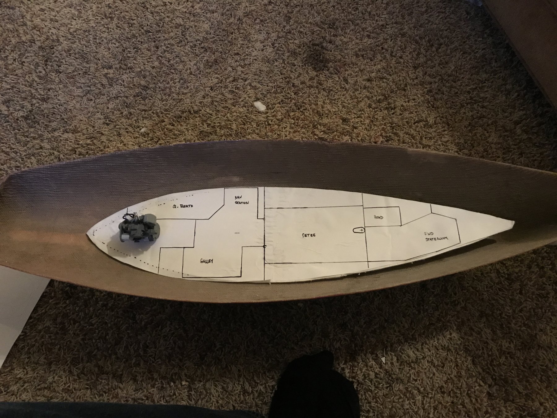
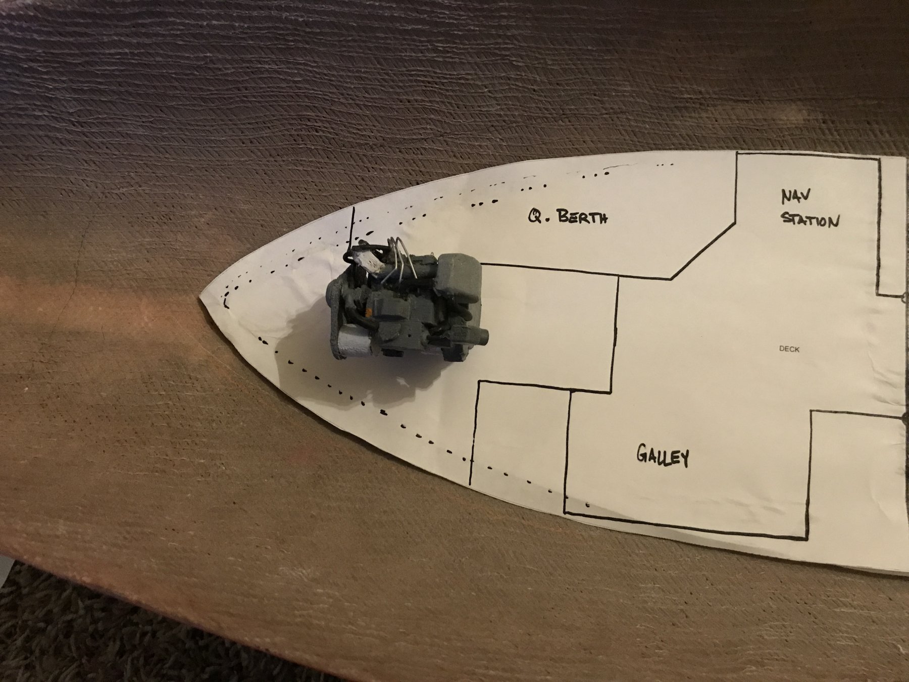
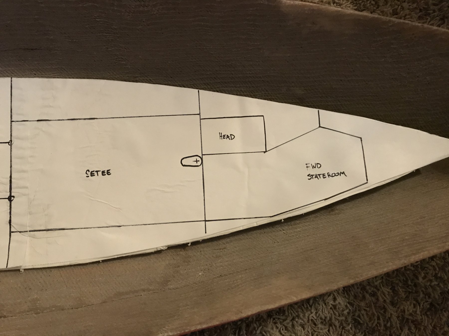
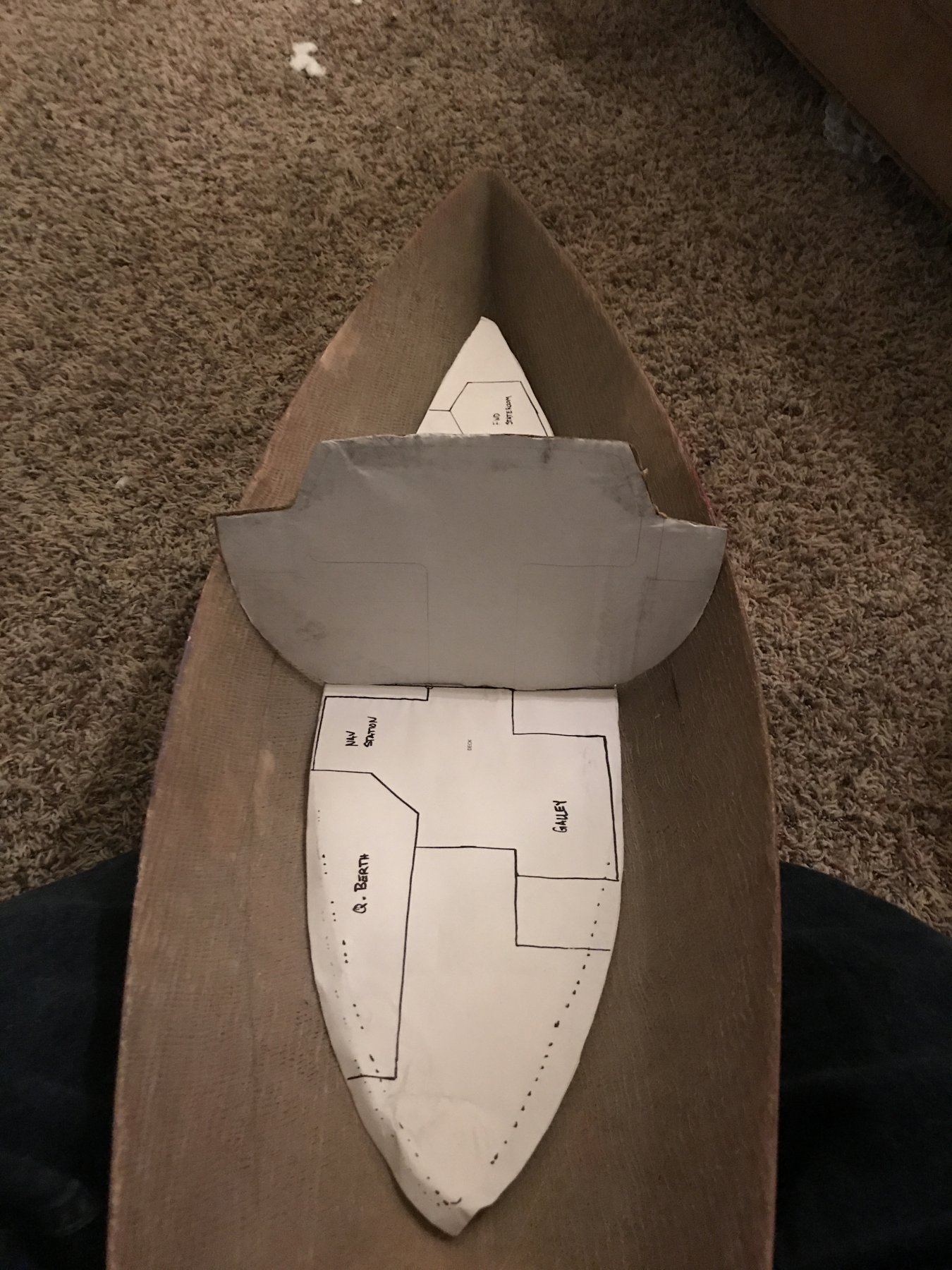
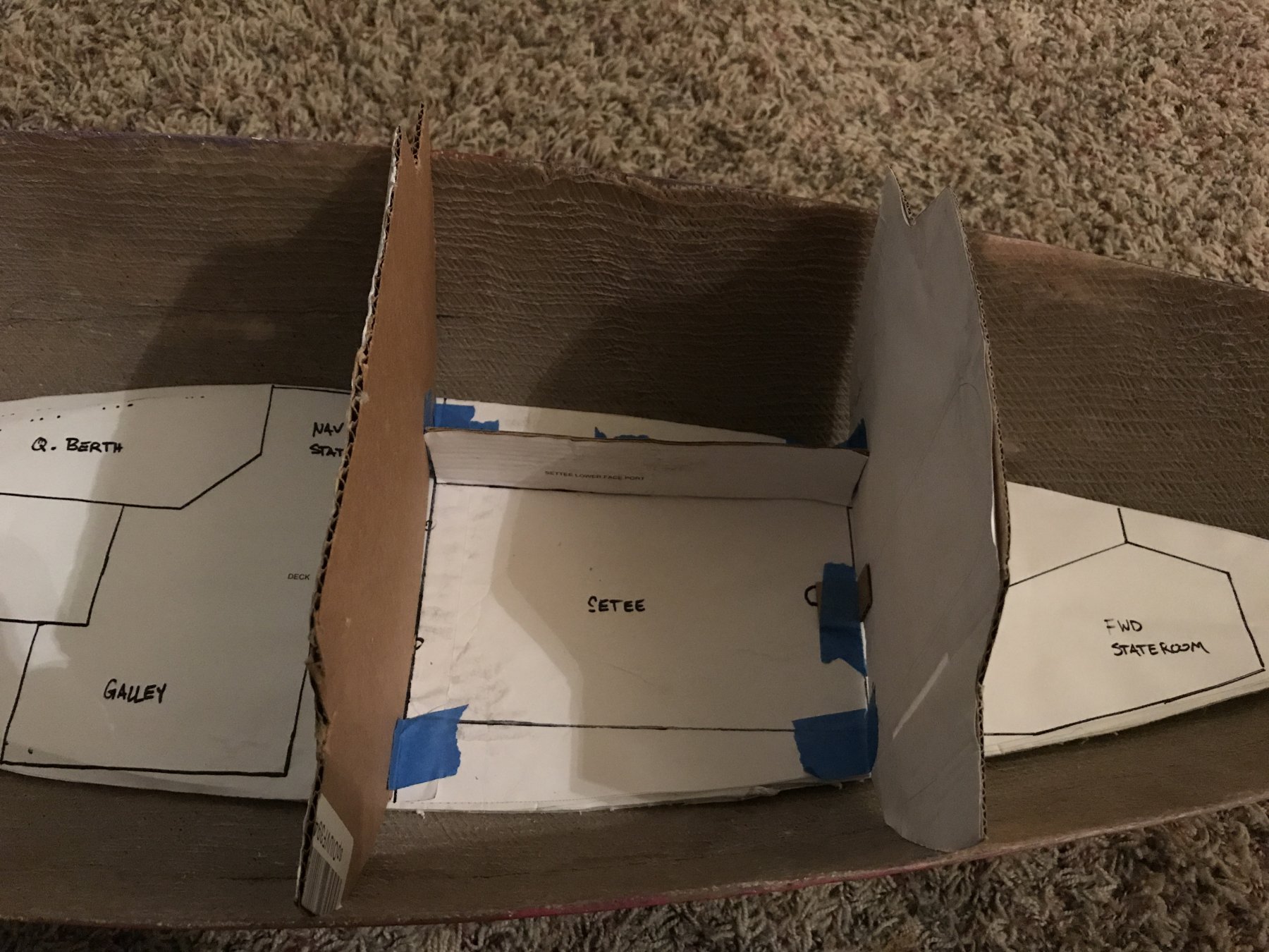
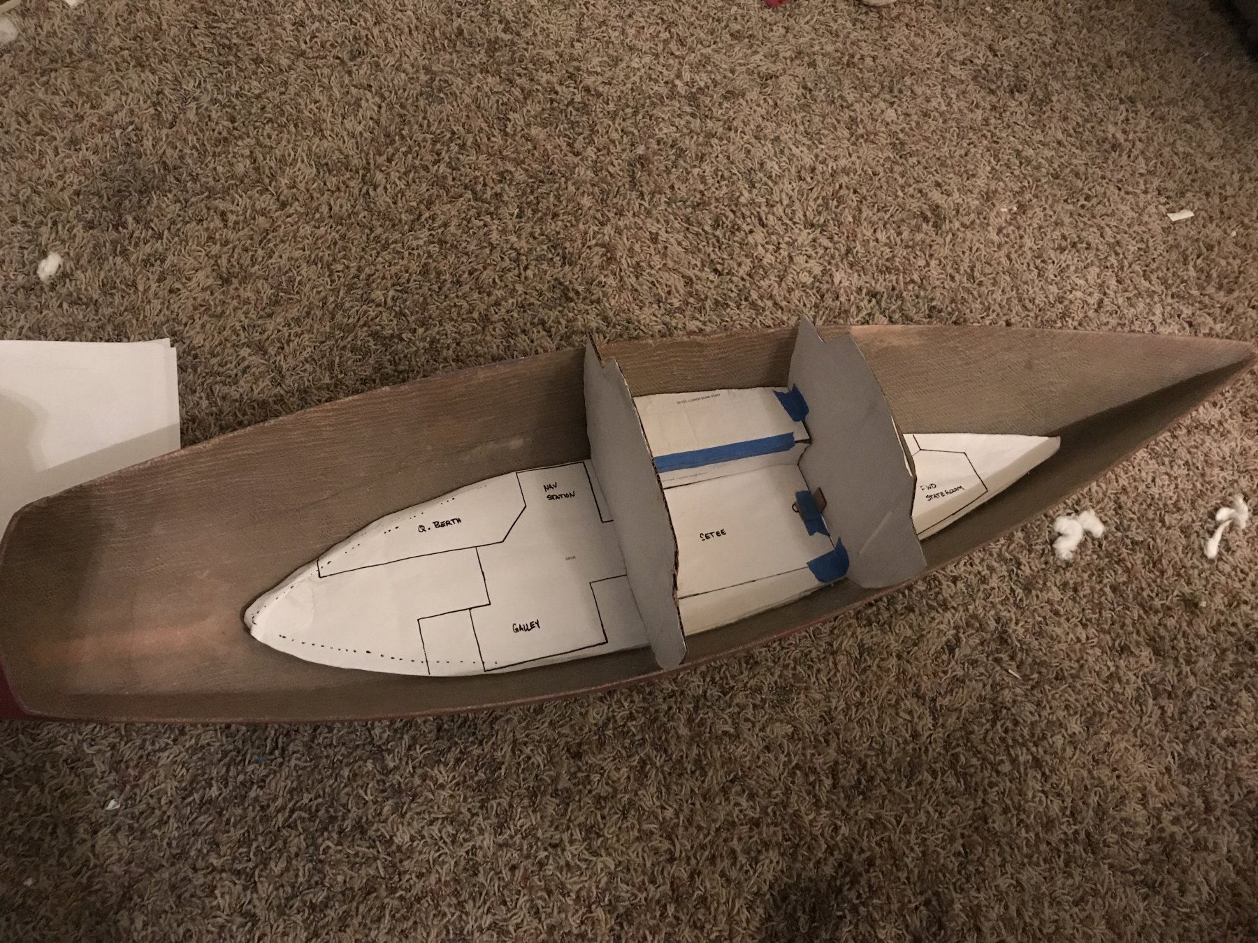
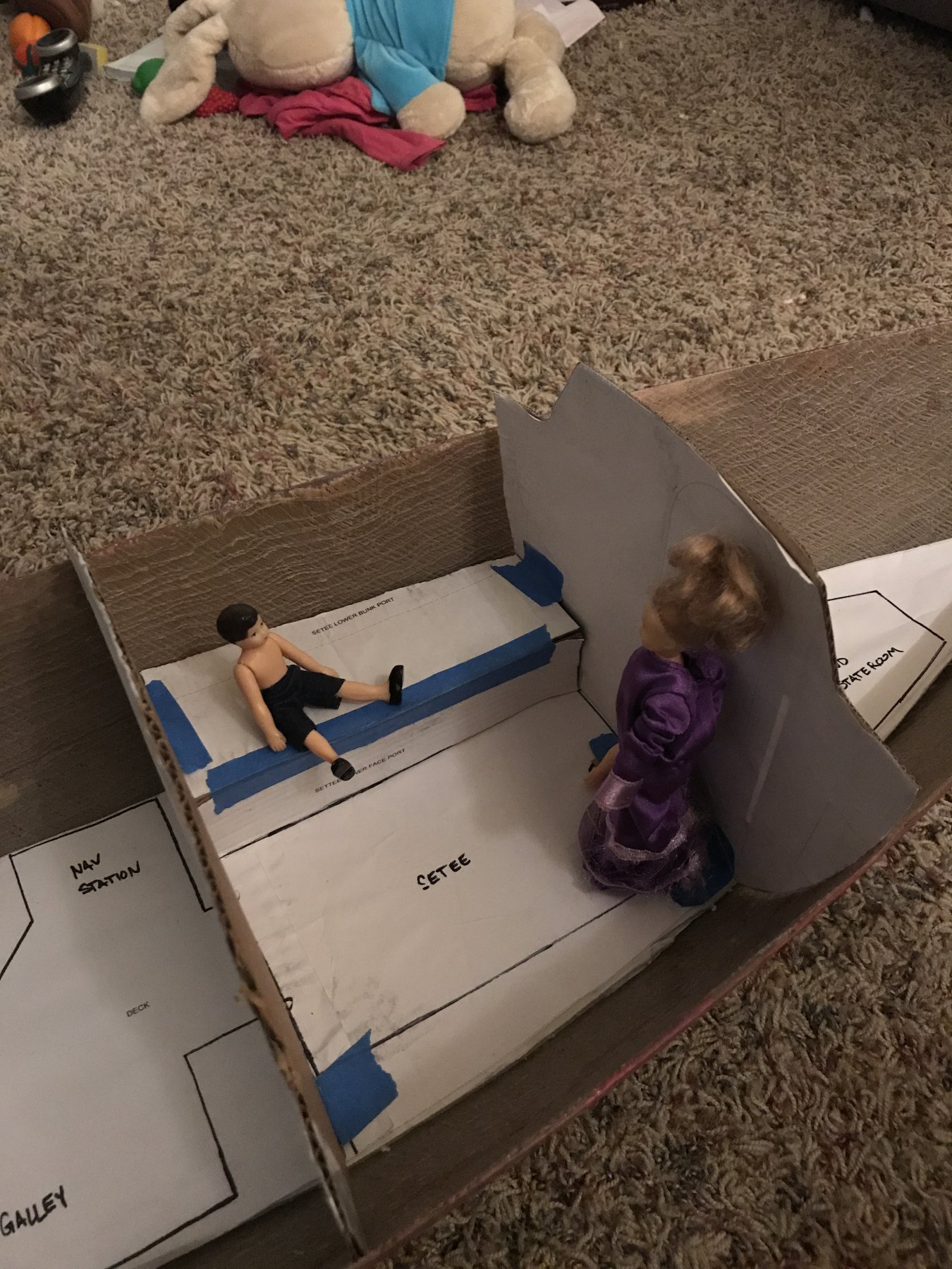
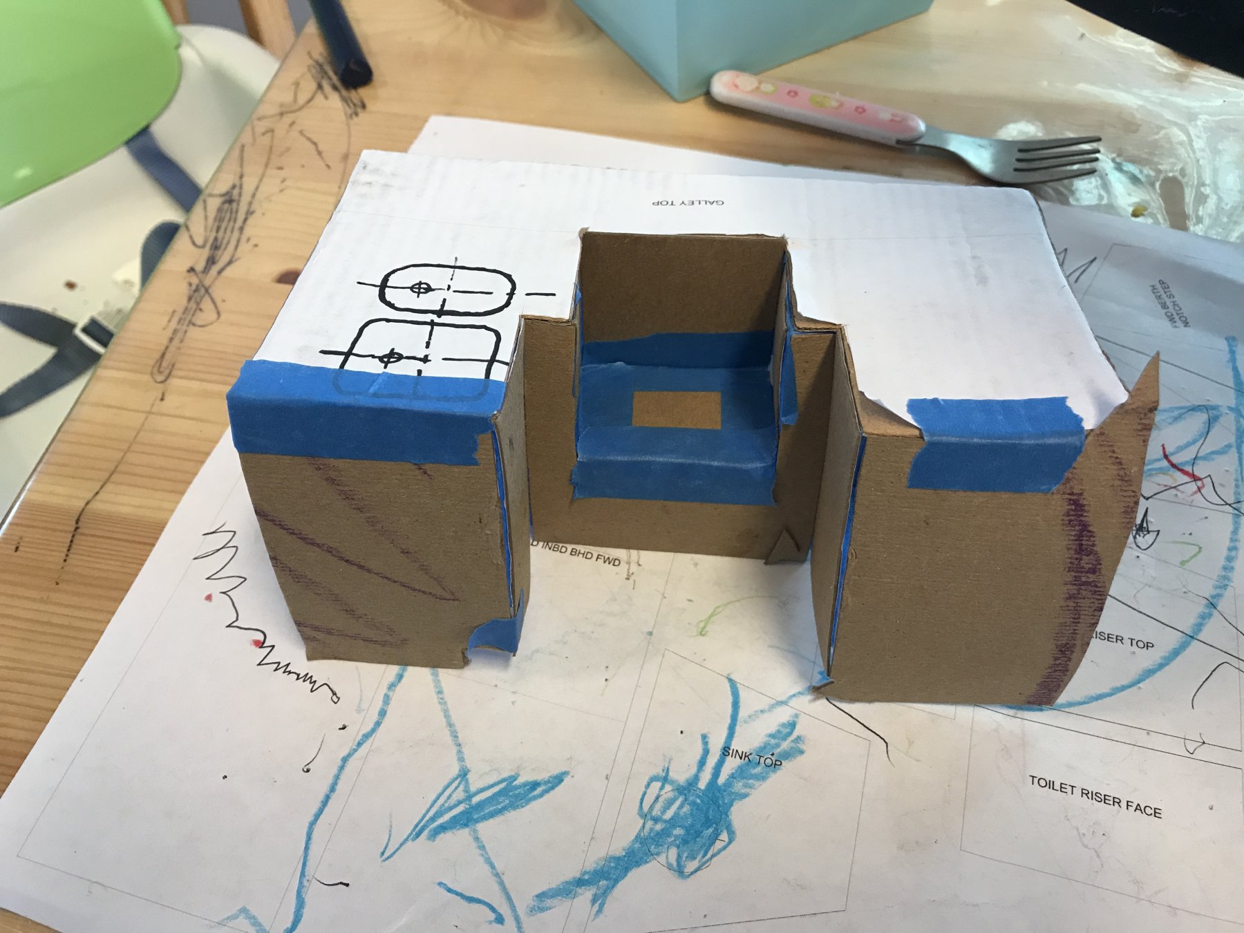
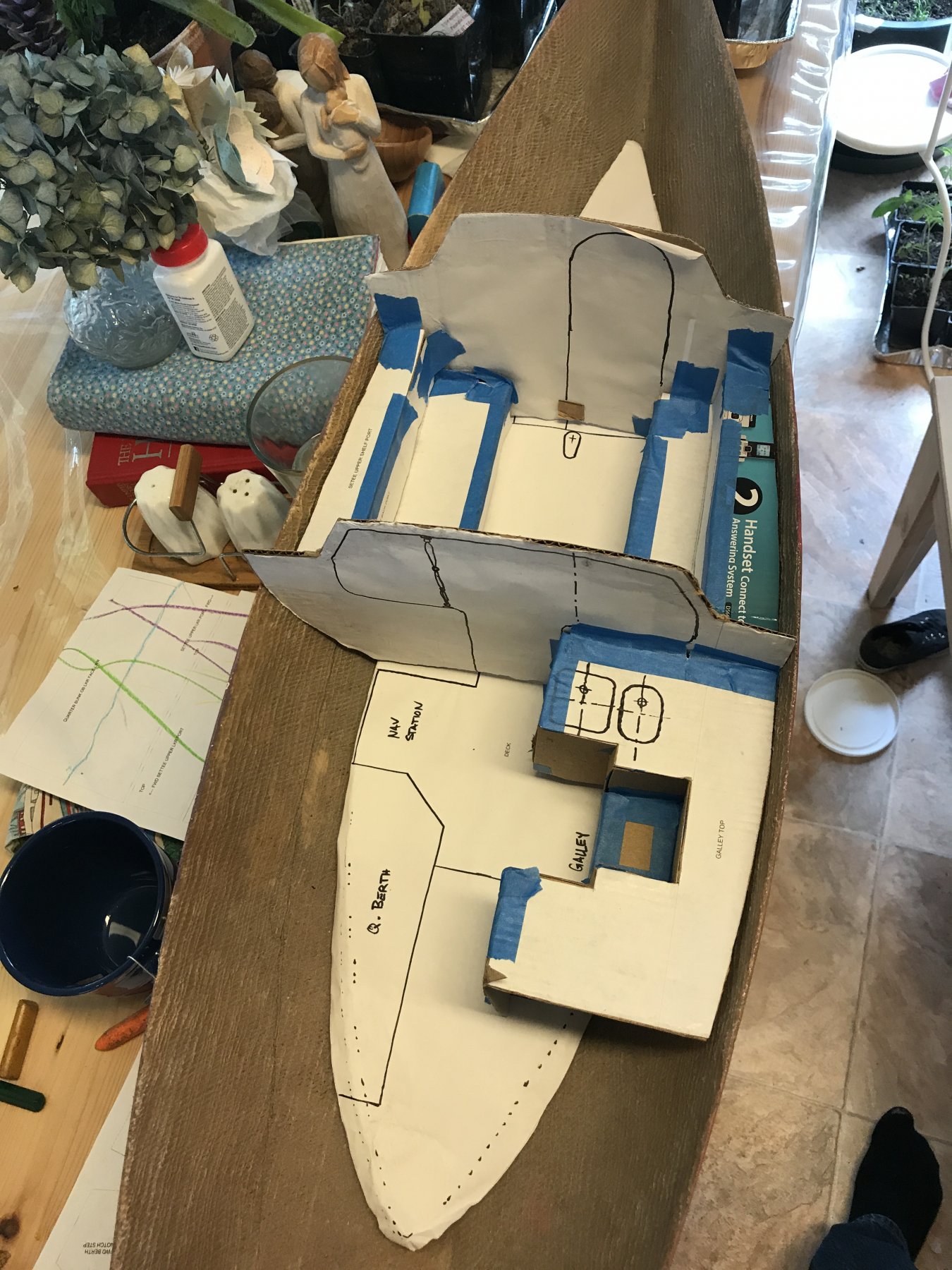
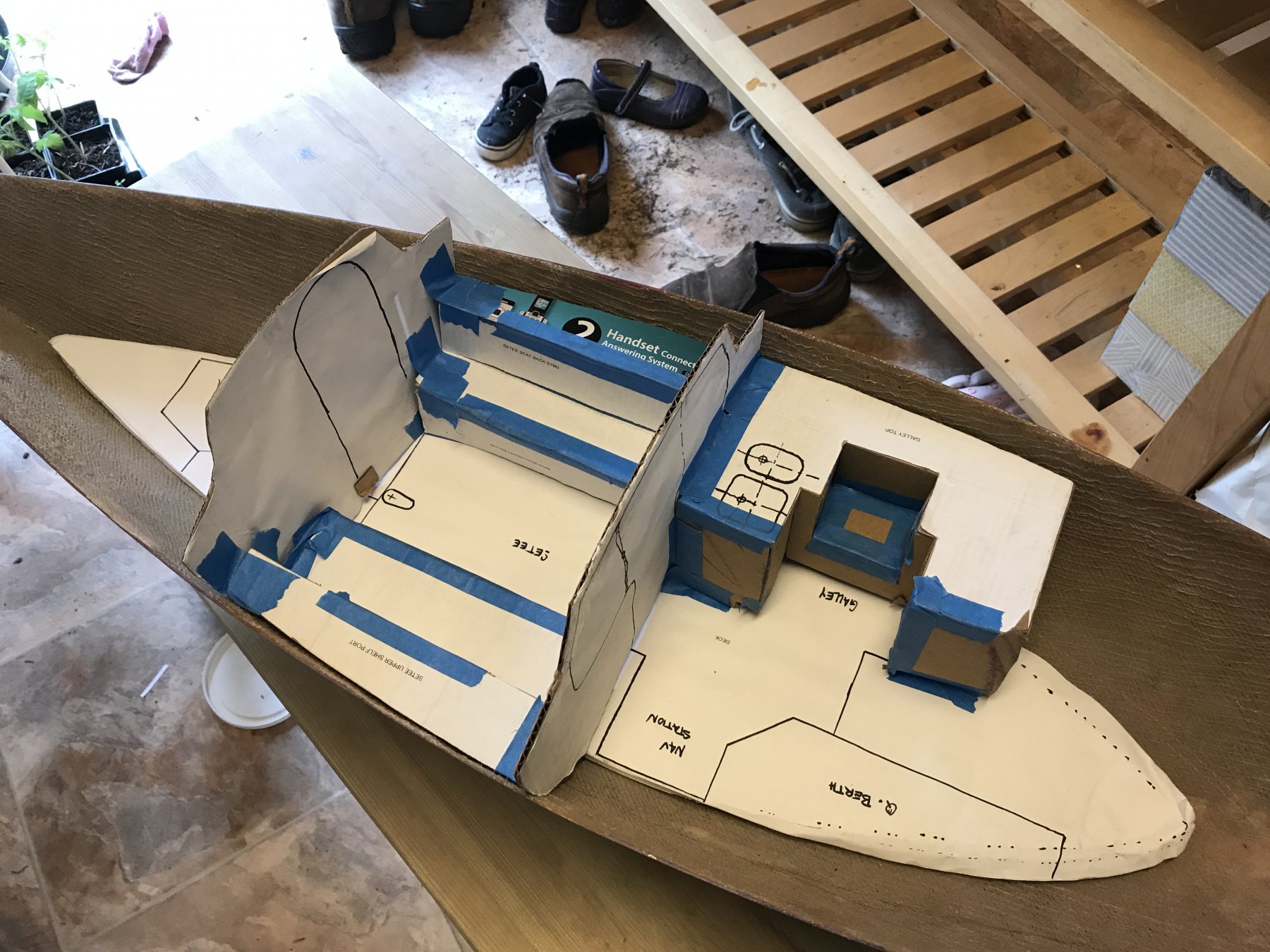
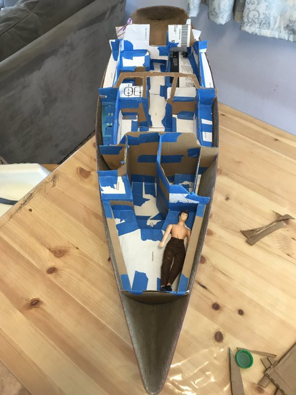
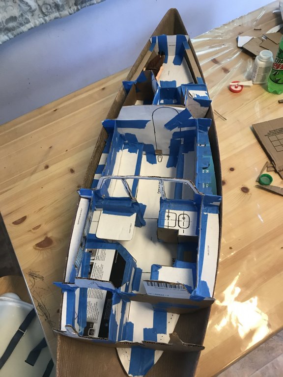
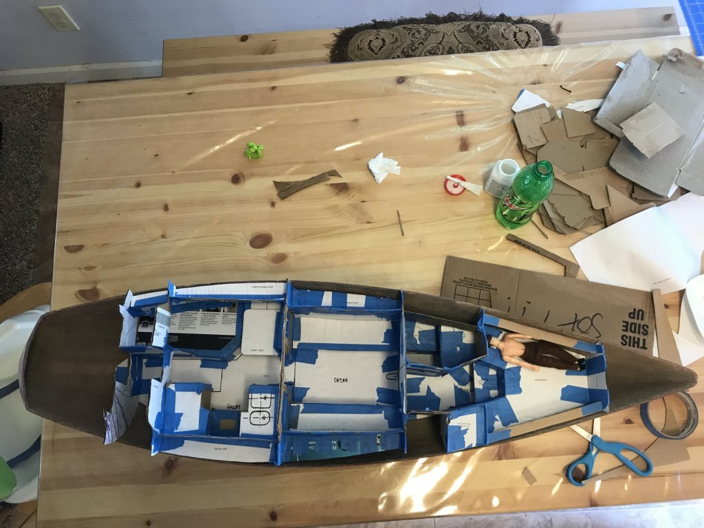
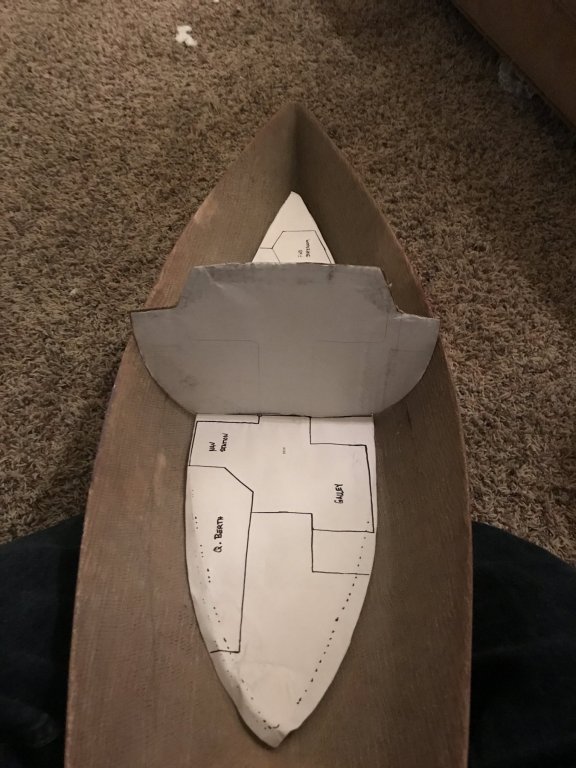
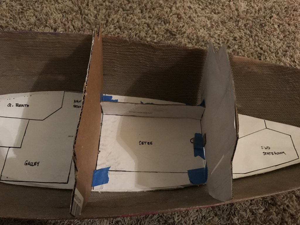
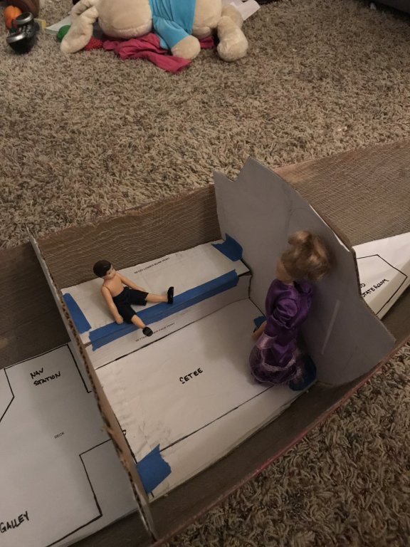
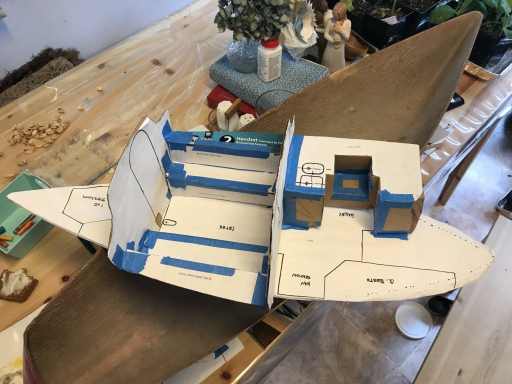
INTERIOR CONSTRUCTION TEMPLATE - PART 1 I printed my 11x17 sheets of paper, and started making and fitting cardboard templates. It has been going better and worse than I expected. Better, in the sense that most pieces fit together, things tend to line up right, and there is general confirmation of all the up-front design work I put in. Worse, in that it's a really tedious, time consuming process to cut the template out from paper, glue it to a suitably sized piece of carboard, cut THAT piece out, then use a lot of muttered four-letter-word-substitutes (there are kids around, after all) and a lot of tape to mash the part in place. Also, for all the attempts at getting the hull form, things still don't fit the curvature quite right. I'm beginning to think that an imperfectly made from scratch hull would be easier to work with than a perfect pre-made one, since with the imperfect scratch built hull, I'd at least have all the information I used to make it! That said, I'm more excited than frustrated, because after over two years of designing and mulling it over and stopping and starting, I can tangibly experience what this is going to turn out like. So, here's some pictures of the progress thus far: Deck Template, with Engine Model for Location/Size Reference Deck Template Detail Aft Deck Template Detail Fwd Below is a big milestone - the first bulkhead template installed! It does (mostly) fit well until the turn of the bilge. Oh, except it (and the other bulkheads so far) are taller than the sheer line. Not sure how that happened, or what I'm going to end up doing about it. That's a problem for future me, though. He'll deal with it. First Bulkhead Template Installed Second Bulkhead and First Piece of Port Settee in Place Settee Construction Intermediate State Dolls at 1:12 Scale, for Size Reference Below is the sub-assembled galley. This went together really nicely, and was a good way to think and plan through the real construction process for the galley. I can definitely build it as a sub-unit off the boat, then fit it in once put together. I'm going to try that same approach with aspects of the nav station, quarter berth aft, and the fwd Vee berth. Galley Sub-Assembly Interior Assembly, Current State I did find, when I installed the galley into the larger assembly, that for some reason it shifted aft 3/8". I'm not sure why, but some combination of compounding errors in positioning and material thickness threw it off. Before going into final construction parts cutting, I need to look at everything with thickness again (or, if I haven't done that, do it!) and adjust the parts to suit. Galley Detail Template Assembly, Current state That's all I've got so far, but things are starting to move along. It's been really nice to be out of the computer and actually making something. But, in general, the time spent designing and planning has been beneficial. This coming week I'm going to finish up the aft end, then start working the forward end.


-
I'm struck by how much like a superyacht this looks every time I see it. From the fantastic hull form to the the completely fiberglass-with-fairing compound-and-gelcoat look of the superstructure. And, of course, the interiors! It's a blast to watch it all unfold.
-
Well, I finally finished getting all the parts onto the wood sheets, and transferring to the 11" x 17" size sheets for template making. Took so long because soon after the last post, work ramped up on a major bid, which we just finished putting together. Such is life, it seems. Anyway, here's a shot of the final set of lofted parts. Once I print these, then it's back to physical building work as I glue to cardboard and then test fit everything. I'm happy to be done with major computer work for a little bit.
-
Hi Patrick - I didn't mean at all to say there was a problem; my point was that they're satellites (probably) so they CAN be that close together. It was a comment on terminology (radome/radar vs satellite) rather than the actual arrangement of the build. Sorry for the confusion! That said, bdgiantman is probably right - they probably serve different purposes - some combination of radar and satellite communications.
-
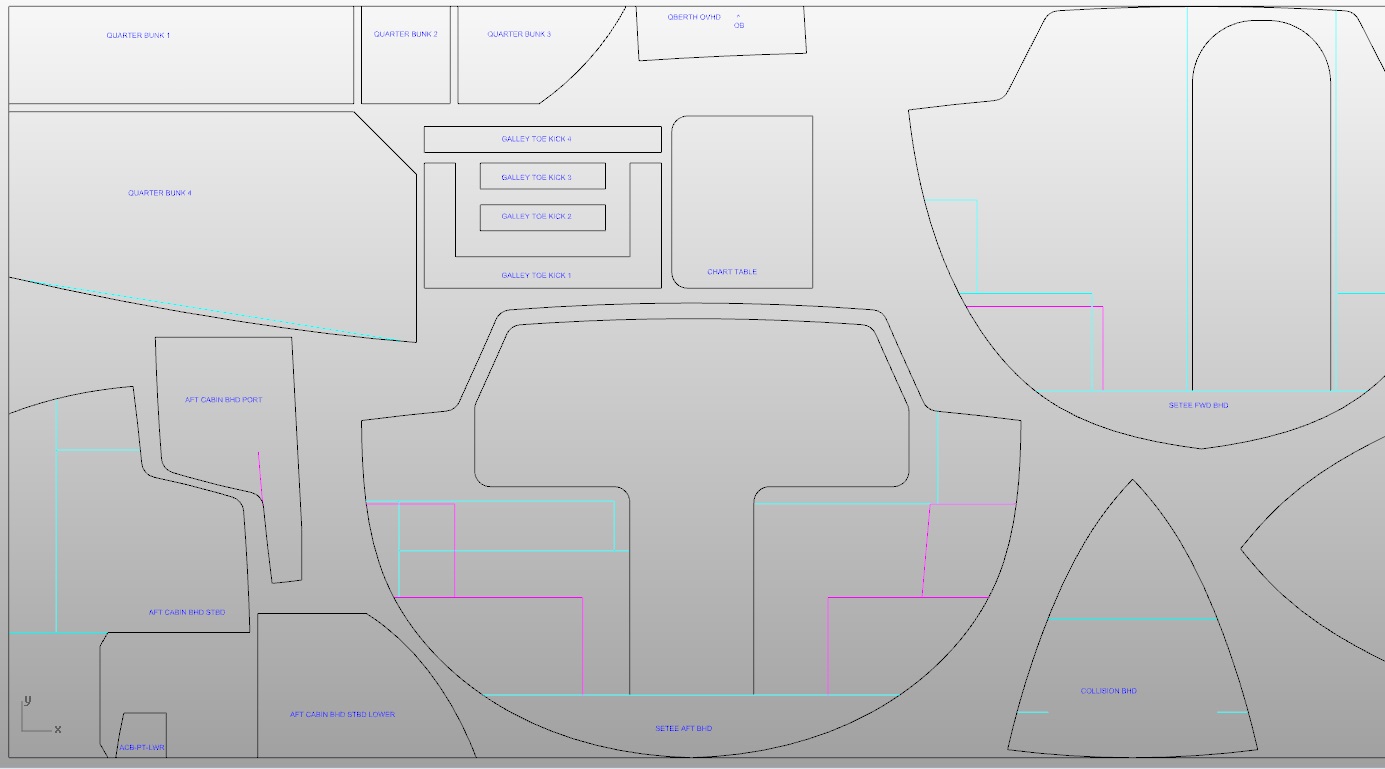
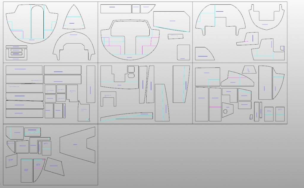
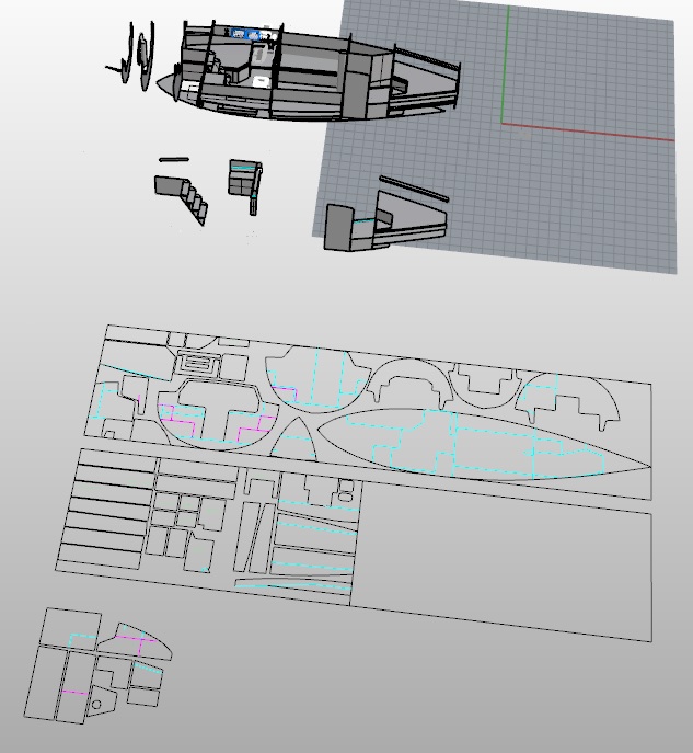
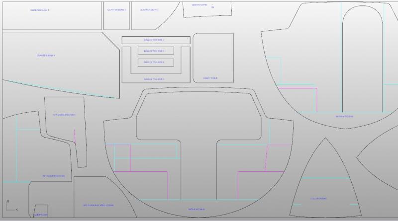
Quick Update (since it's been 7 months since my last posting). I got 80% through turning the 3D model into flat parts to template out, then lost steam for a variety of reasons, the most significant of which not having time at the computer to finish. That's still the status; that said, I'm beginning to get the modeling itch again, with some major home projects complete. I've also saved up a lot of thin cardboard, so I can pre-fit and template the parts, using the cardboard to loft out the actual parts on wood. Plus I also have a friend now who has some woodworking tools, and can help me get the parts cut (my other big mental roadblock). Anyway, two shots below of the process. The first is a view of the whole project - the 'master' in the background, with a copy in the middle where I delete parts as I get them laid out on the sheets in the foreground, to make sure I've captured everything. The second is a closeup of one of the sheets, showing how I'm nesting, marking, and labeling the parts. Light blue lines are 'this-side' intersections with other parts, magenta are 'far-side' intersections. Parts Layout Process Part Marking and Labeling Detail Hope to get some more progress soon. My next step is to take what I've done and copy to 11x17 size so I can print them on a standard printer (should have thought of that in the first place...) and then make the first pass at cardboard templates.
-
Hiya Patrick, I have to say, I'm glad you haven't been moving break-neck speed, so I didn't miss the whole build! I know what you mean about life being crazy on-and-off - haven't gotten on here in months between travels with family, work responsibilities, and general miscellaneous stuff happening. So I was worried that you were all done and off on something new. But I'm happy to see that you're really just getting in the thick of it. It's looking really wonderful so far! And, PS - the domes are for satellite dishes so that the owner and guests and crew don't miss their favorite TV shows while sitting offshore of Tahiti or something. Three radars that close to each other would interfere with each other. Doesn't impact the way you built it at all, just a fun knowledge tidbit Keep up the excellent work!
-
Count me in! I like the way she's shaping up already - the bow form and bulb looks good from what can be seen in the pictures.
-
Looking very nice, Patrick! I'll echo the comments that I can't wait to see what else you could possibly do to finish her, and, of course, can't wait to see what you're planning next!
-
Thanks Bob! I like it better, too. There is a lot of sense in not re-inventing the wheel; there is a reason many small sailboat interiors are very similar - because they work. I appreciate the input! And, it looks like I need to find a friend with a scroll saw or band saw, since the CFO for our household will certainly not authorize that purchase for some time...
-
Yup! Our Freshman year at Webb we had to do a hand-drawn lines drawing for a small 12 ft sailboat from a table of offsets. Splines, ducks, ship's curves, ticker tape, all-nighters...ah, the memories. I do a lot of hand sketching for initial concepts, but (for this model project at least) I've found that I can produce a functional 3-D model faster than I can produce a neat, legible drawing or diagram. And it makes it easier to visualize the interaction of the parts. For the engine I scratch built, using a downloaded 3D model from the Yanmar website was invaluable for taking components off of, making 2D projections at the scale of my model, and using them as templates for making the parts. That said, when it comes to choosing between a well done hand drawn technical diagram, and a computer generated one, I'd take the hand drawn one every time. I have copies (not originals) of some of the builder's drawings of the SS Edmund Fitzgerald from 1958, and the quality is better than many technical drawings I review as part of my daily work. Plus there's that humanity added by still visible guidelines that didn't get fully erased, and minor inconsistencies in ink thickness, etc. that bring out a certain charm. If I had enough wall space they'd be hung up all the time.
-
Hi Roger - thanks! I studied at Webb Institute on Long Island. Graduated 2011.