HOLIDAY DONATION DRIVE - SUPPORT MSW - DO YOUR PART TO KEEP THIS GREAT FORUM GOING! (Only 13 donations so far - C'mon guys!)
×


BenF89
-
Posts
316 -
Joined
-
Last visited
Content Type
Profiles
Forums
Gallery
Events
Everything posted by BenF89
-
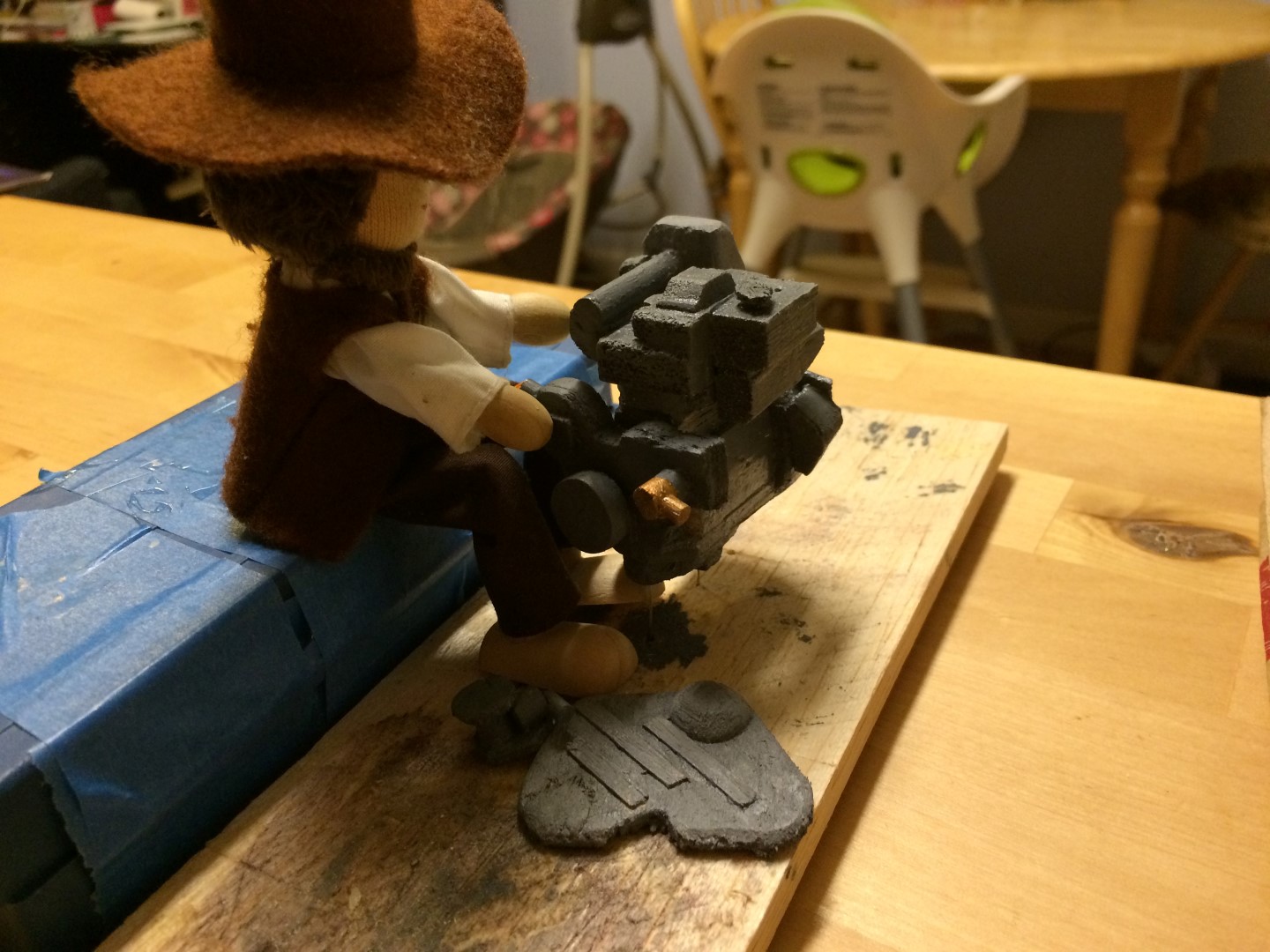
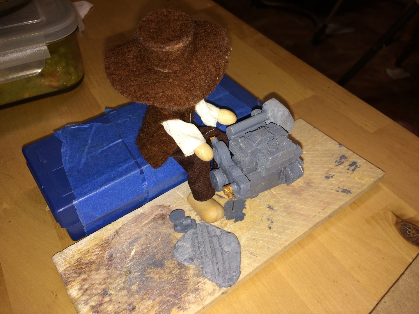
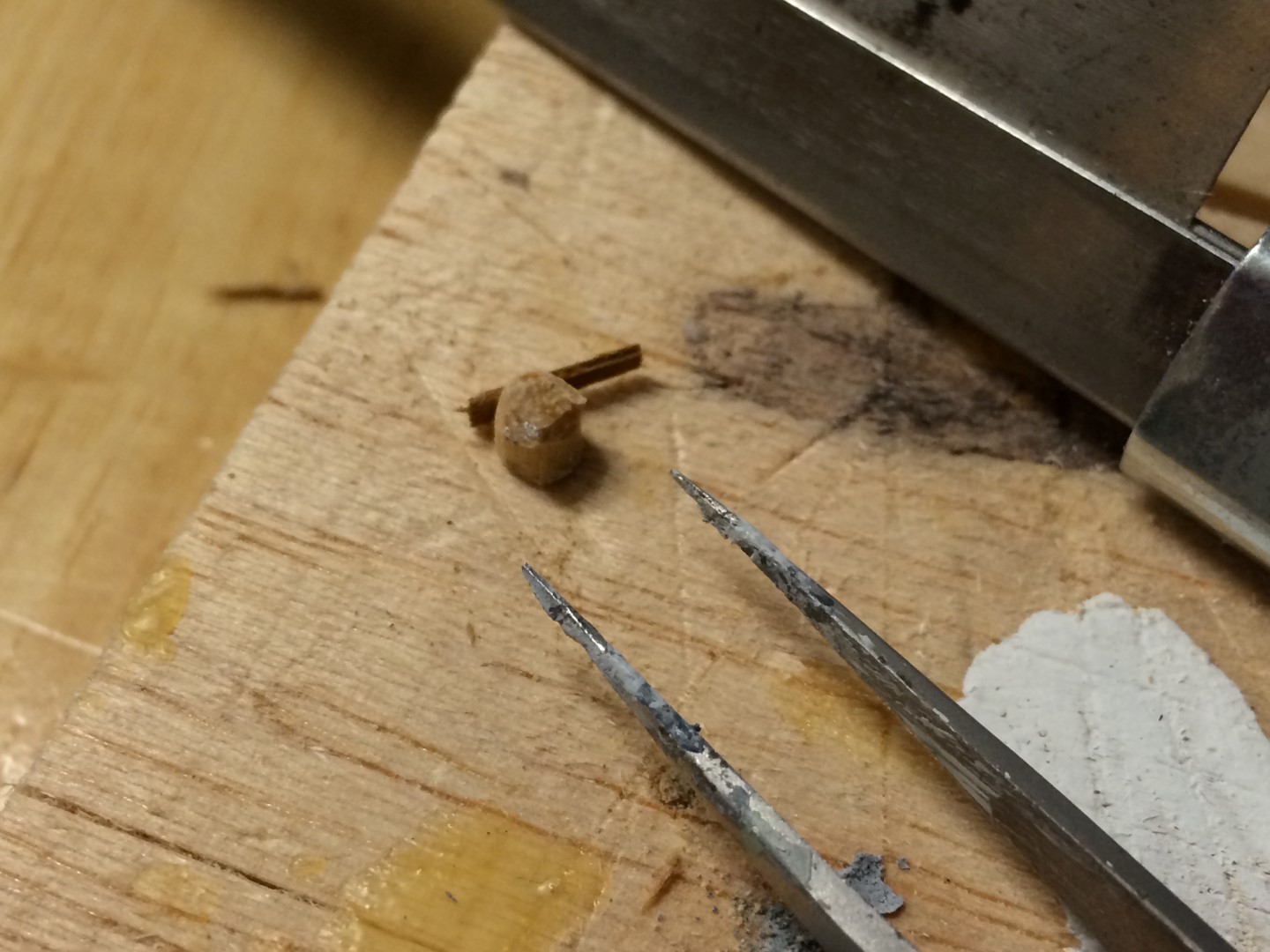
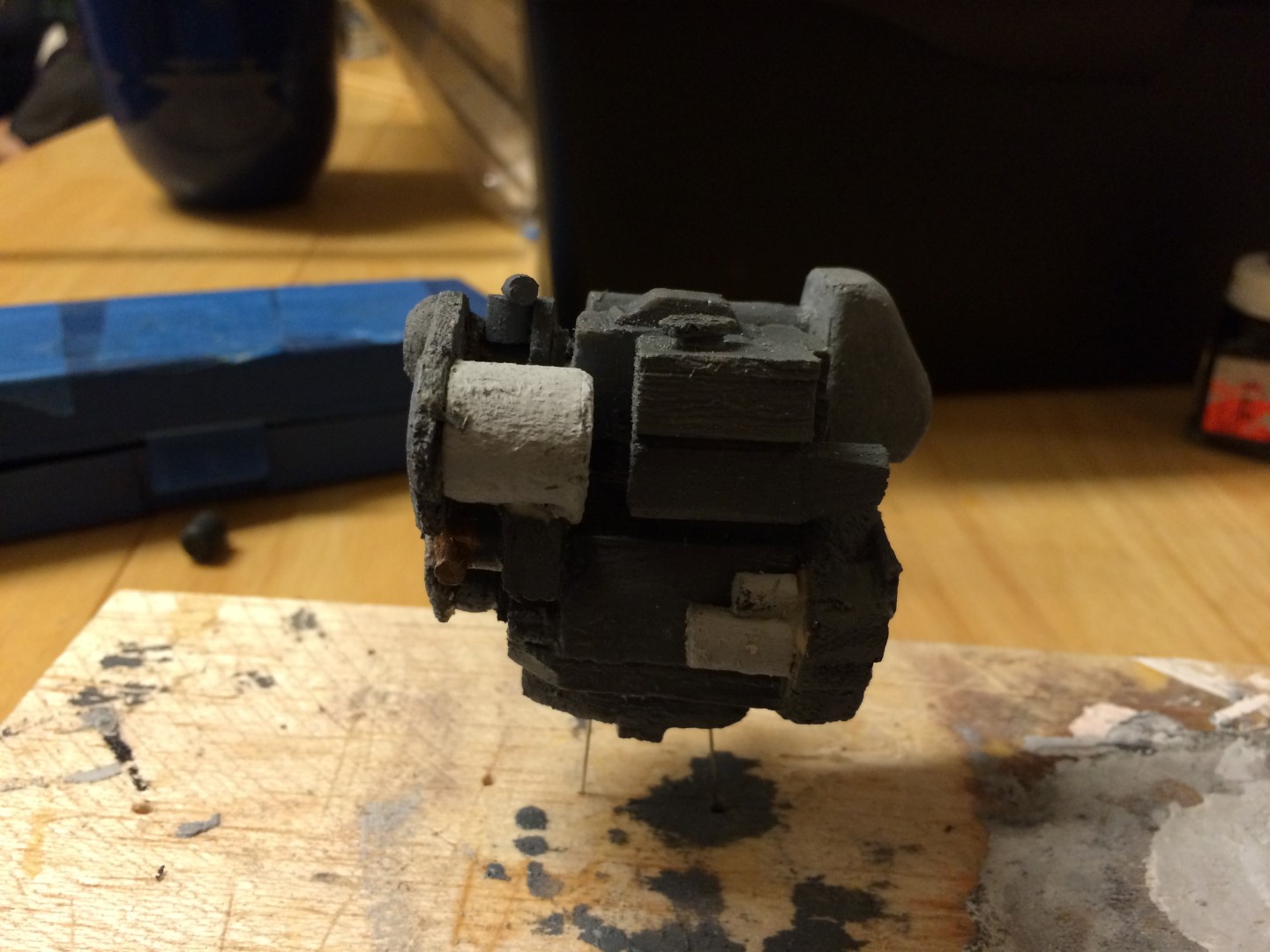
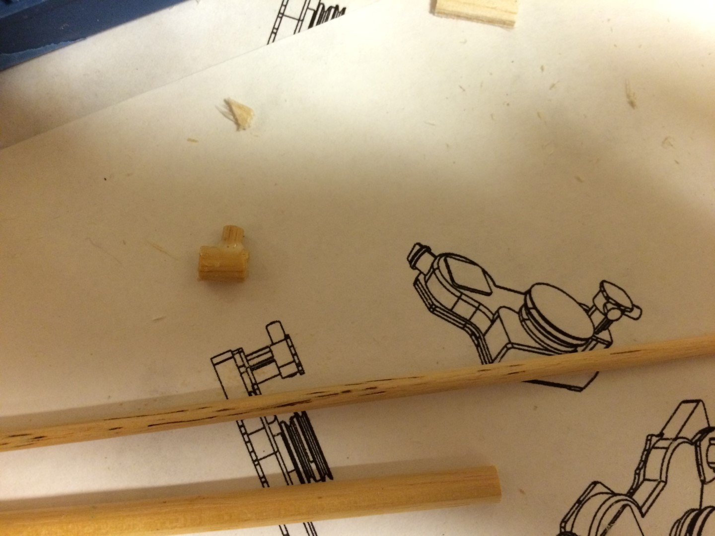
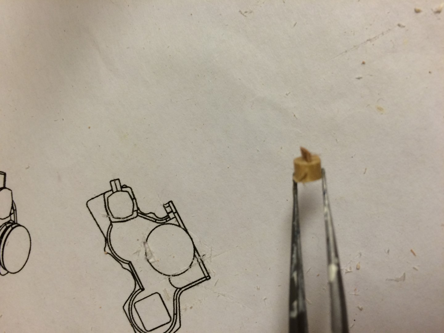
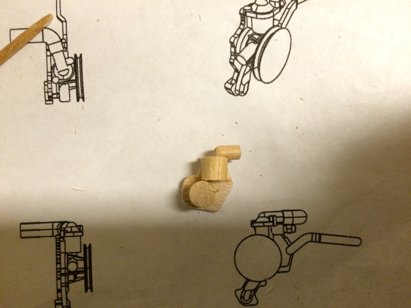
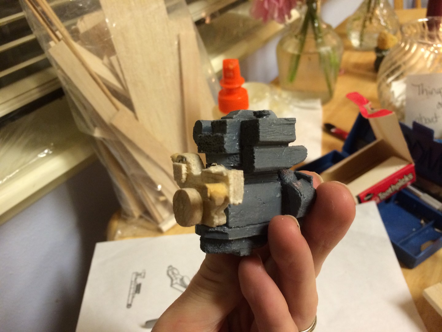
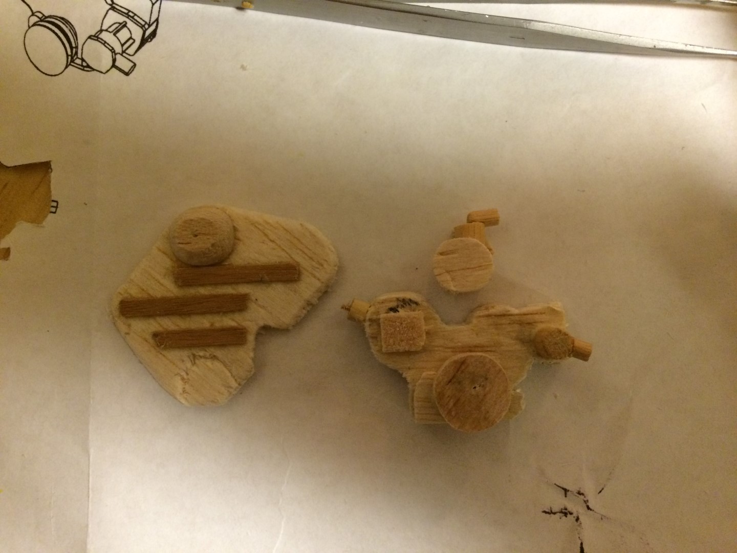
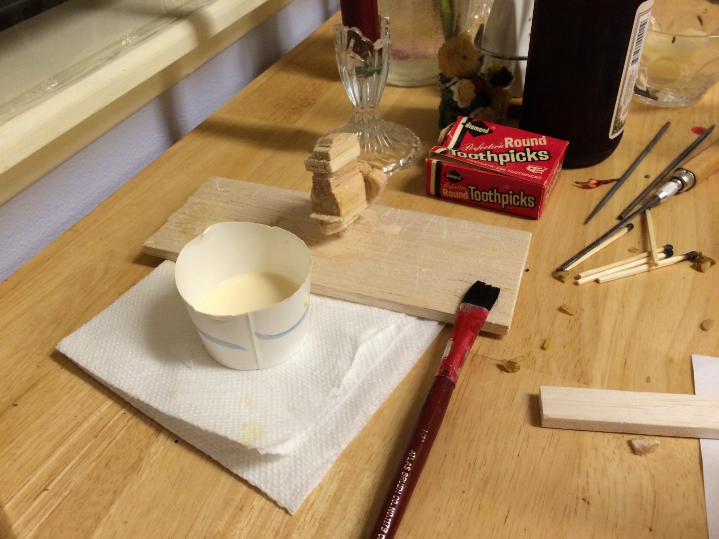
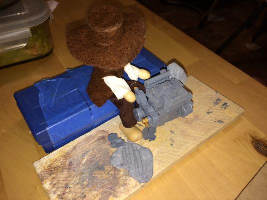
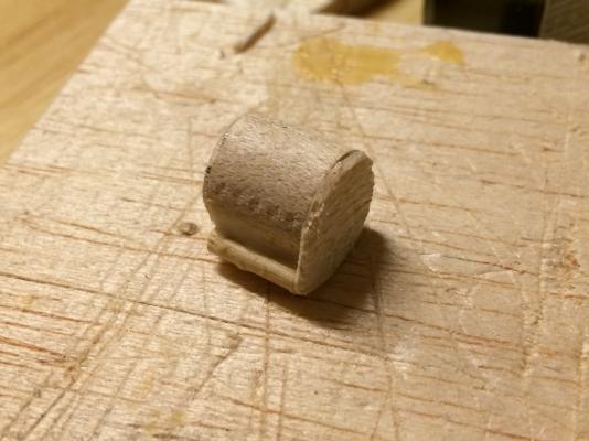
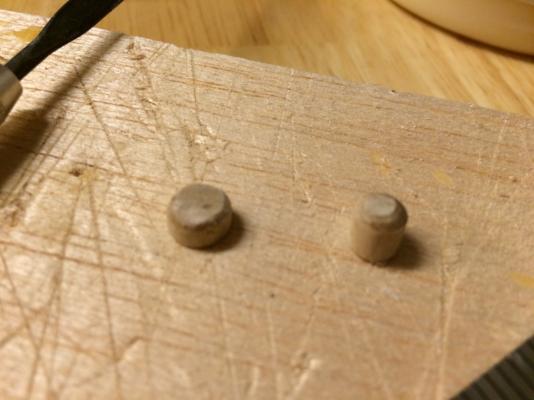
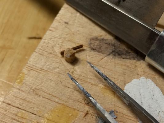
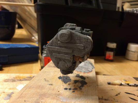
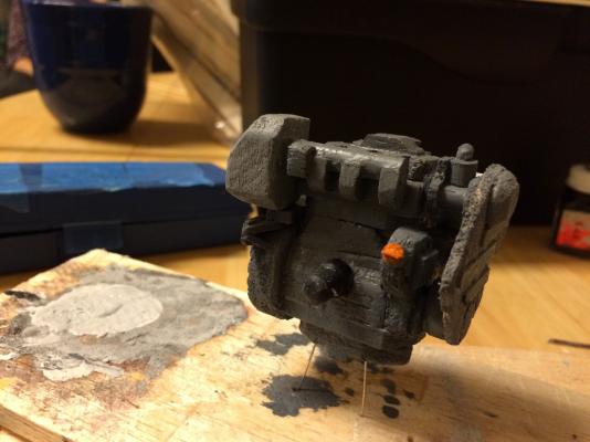
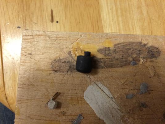
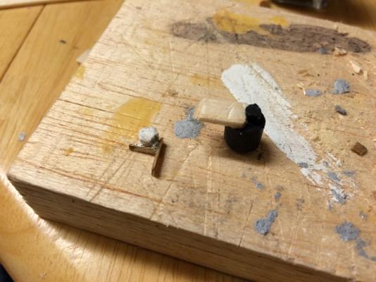
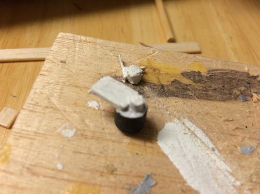
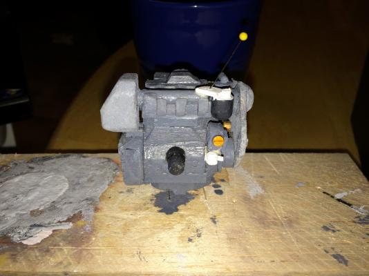
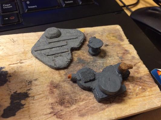
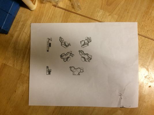
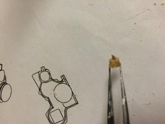
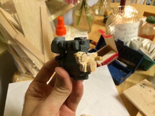
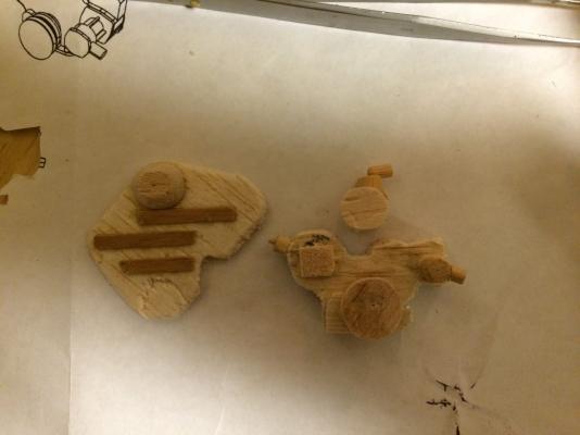
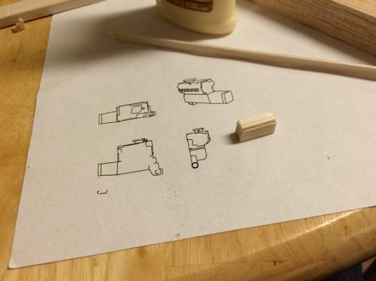
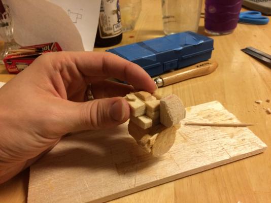
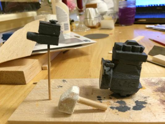
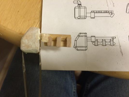
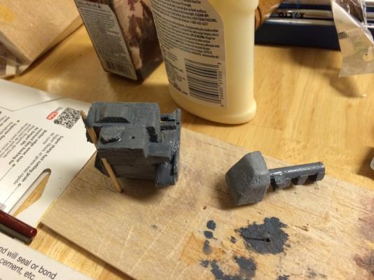
 ENGINE ALTERNATOR, STARTER MOTOR, AND LUBE OIL FILTER So, I got the dowel sizes I needed and finally got some time to get back to work. I started by making the alternator, starter motor components, and lube oil filter (I think). Most of these parts were pretty simple compared with the lower front end assembly - mostly all dowels cut to length, with a few cut shapes sprinkled in. The first was the alternator. Very basic - length of appropriate sized dowel cut, length of smaller dowel cut (for the mounting bolt/brace/thing), and a balsa 'cap' plate made from the thinnest material I had. Alternator Assembly prior to Paint Then, I made the two components for the lube oil filter - a larger 'base' and the smaller filter component. (Note - I call this the lube oil filter. I based that on the location context and where the hoses attached to it run. I actually am only 75% sure this is actually what it is. But that's what I'm calling it. So, take that, Yanmar and your unclearly labeled, freely available tech specs and plans.) Lube Oil Filter components Next I made the two dowels for the starter motor assembly. I didn't take in-process pictures, but these were also just two pieces of dowel cut to length. So then I mixed up some paint. (Which took two tries and almost all the white paint I had because I am terrible at mixing paint and I really just botched it up a lot and next time I should just wait until I can get to a hobby store and buy the color I need rather than spend a long time and a lot of paint just to botch it up. Phew.) I painted the alternator and starter assembly, as well as the lube oil filter which was fortunately just black. FUEL SYSTEM COMPONENTS While I waited for the paint on those pieces to dry, I started making parts for the fuel system, starting with an impossibly small little thing (that I don't know what it is or does but connects to the on-engine fuel filter) and at 1:12 scale is REALLY small. Patrick - I don't have ANY idea how you do EVERYTHING that small. Ugh, I'll just continue watching from the sidelines. Fuel System Part that is really small. FINISHING THE FRONT END So, then the paint on everything dried sufficiently to glue it all up. Including all the sub-components of the front end - woohoo! Sub-Components Added #1 Sub-Components Added #2 Sub-Components Added #3 - the black thing is the Lube Oil Filter Prior to putting this together, I had painted the fuel system parts. I also realized (doing a test fit) that the each needed brackets. Painted Fuel System Parts Brackets Added Brackets Painted By the time I finished the assembly work on the engine proper, they had dried (enough) to get on as well. (I was just a little impatient, so they may not have been completely dry. But it worked out.) Current State of Engine #1 Current State of Engine #2 Current State of Engine #3 An interesting note, is that in the process of putting all these pieces together, the 'that looks about right' sizes and lengths and shapes are catching up to me, so to speak. All the parts have gone together, but some took a little persuasion, and others are in mostly the right place but not exactly the right place, which will make routing hoses and adding some of the other remaining parts interesting. But, overall, I am happy with how things came together. For this being the first time I've scratch built something so complex (and the second time I've scratch built anything at all for a model), I am happy with how it's going. Next up is to add some more components to the fuel system (which is by far the most complex series of parts, hence putting it off), and to start running hoses. I had what I hope is a stroke of genius a while back on how to do the hoses. But you'll have to wait until next time to see it. (That way, if it's actually a terrible idea, you'll never know that it failed miserably and what I actually do is Plan B ) P.S. While I was bored one morning, I saw Pa Pioneer lying around, and my engine assembly on the counter. So I took some still-life shots of Pa working on the engine. I enjoy the juxtaposition of his very old fashioned, almost Amish look, and a modern sailboat engine. Mechanic Pa Pioneer #1 Mechanic Pa Pioneer #2
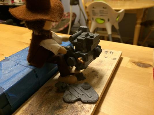


-
Woohoo - I think one of my favorite parts of your builds is seeing the bulkheads start going up. Looking good! Now, are we looking at one deck above the lowest? It seems there isn't a lot of space for an engine room on this level, unless they are wedged in forward of the tender bay (which, actually, wouldn't surprise me.) Of course, I could just flip back through and look at the plans again. But that would be too easy.
-
I suppose it depends on how engineering-minded you are. I think I'd keep the hydraulics visible - but then, one of my favorite book genres is the large Cross-Sections books that expose all the hidden inner workings of everyday things. You know, the ones they have in the children's section at Barnes and Nobles booksellers.
-
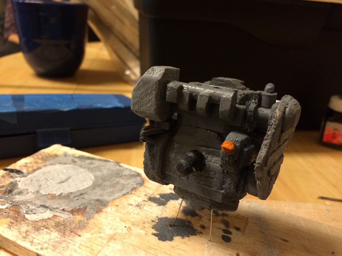
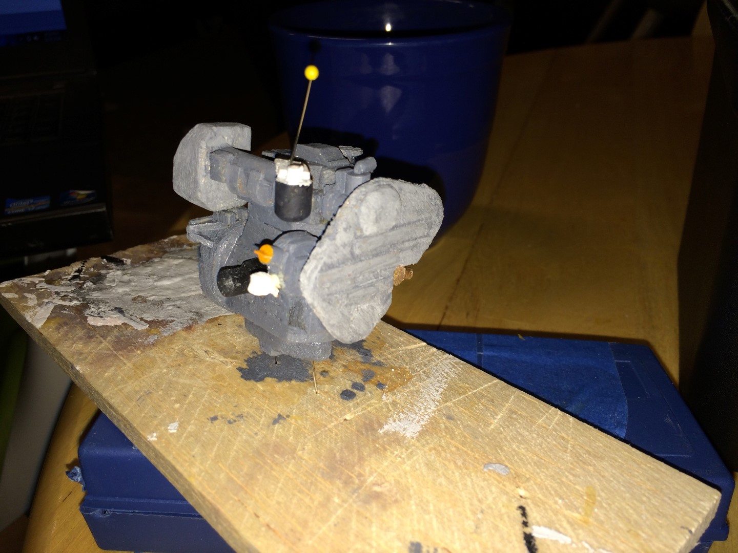
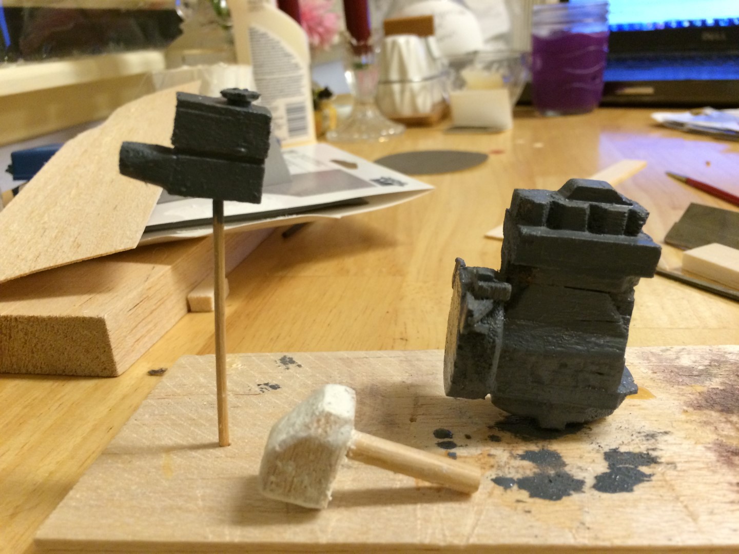
Thanks for the comments and likes! Dennis, If by 'big block' you mean a real engine (like a car or boat engine), I am woefully inexperienced. I do not have much of a mechanical aptitude. I kind of know about engines, but I leave any tinkering to people who do that professionally - I'd botch something up if I tried to do anything, even change the oil! Any knowledge I have is all head knowledge from hours in marine engineering class learning about marine diesel engines. I admire people like you who can take engines apart and put them together again - I've only done it twice, each time in a team with other students, with detailed instructions, and they were both single-cylinder engines. One was a Lister-Petter single-cylinder lifeboat engine, and one was a single-cylinder demonstration version of a Low Speed Diesel (the type where the height of the engine required multiple platforms and stair sets to get from bottom to top). Our class split into two teams; one team disassembled the cylinder head, and the other disassembled the piston (which was a two-part deal - the piston and the crank, coupled by a cross-tie). Then the team that disassembled the cylinder head re-installed the piston, and the team that took the piston apart re-installed the cylinder head. It was a neat exercise, but did not leave a lasting mechanical skill set, at least for me. Anyway, Small Update: Tonight, just to get back in the swing of things, I painted the parts I had made last time. I found an excellent link with a lot of hi-res pictures of this model of engine (with a normal gear vs. a saildrive) that is going to help immensely with getting the colors right. (http://svbreakaway.info/boat-projects.php#repower) So, one assembly had some new colors, other than gray and slightly different gray! On the big subassembly, there is an orange fill cap, and the seawater pump is bronze. Which I used brass metallic paint for, since that's what I had, but I think it will work out alright. Here's a picture! I need to get some more dowel to complete the next sets of parts, but once I do, I'll have another update.
-
Nice! Now we just need to see the miniature hydraulic power unit, hoses, and arms that will move that beast of a door up and down!
-
Just catching up on the log - looks like great progress. I echo Patrick's comments on the ram - that thing looks MEAN!!!
-
Hi Patrick, Been wanting to comment but with getting back to work and then settling back in at home and then a windstorm knocking power out for a day, haven't made the opportunity. Anyway, I really like that contrasting bottom paint - I wasn't sure how the blue-green would look with the black topsides when I suggested it, but it really makes the hull pop! And, of course, I am as tempted as you are to have you skip right to the interior. I've said it before, and I'll probably keep saying it, but I really get excited about seeing how interiors come together and seeing a 2D concept materialize into 3D, with all the inner workings of the bulkheads and passages and the various fixtures and furniture. I'm even more excited for this boat, given it's size (not the model, the source boat) since there are multiple decks and intricate, separated rooms and spaces. Really stoked to see it come together. You really shouldn't have teased with that aft door and boat hold only to put it off more! You sure know how to keep an audience captive... Take care, and keep up the good work! And, just as an FYI, real yachts are built, insides and all, before they make it shine like a new penny on the outside
-
Hello Michael! I echo all the sentiments about the detail and quality of your project! Very impressive. I also couldn't help thinking that you could take some of the photos, especially the ones taken in 'third person' so to speak, combined with a bunch of the black and white close ups, and make a coffee table picture book! The artistry of many of the photos is as compelling as their subject matter. Very, very nice work.
-
I don't believe that is true as a general statement. I only say this because I interned with a shipbuilder, and while I was there they were constructing a very large (85 meter/280 foot) motoryacht. I was interning with the engineering department, so I had access to all the design plans, etc. I think it had a tunnel thruster at the bow, and it had active roll stabilizers (two sets, fwd and aft). But it didn't have a tunnel thruster aft. And, based on Patrick's drawings, I don't believe this boat has one either. It really depends on customer requirements, I would think. Plus, with a good electronic control system, you can make the boat crab in and out (move sideways) using just a bow thruster and two props/rudders, thus negating the need for a stern thruster. Granted, stern tunnels may be a current trend in large yachts - it's not my industry of expertise, so I can defer that I don't follow all the latest designs and trends closely. If you have some examples, I'd love to see them. But in the yachts I've seen, across a variety of sizes and companies (Westport and Christiansen come to mind), I haven't seen a lot of stern tunnel thrusters. I don't think they are that common, probably because it's yet another potential leak point, it complicates construction, and it adds drag. All that said, I think tunnel thrusters are really cool, and I'd probably throw one in the stern of my own (imaginary) yacht just to do it.
-
Wow. She looks even sleeker than before! Nice work. Can't wait to see how you treat the underwater hull.
-
Hey Patrick! LOVE the impression of the frames and side structure! Looking really great - I think you've really captured the essence. It actually looked like what you'd see in a fiberglass hull - I know you mentioned to me the hull is supposed to be aluminium, so please don't take that as a criticism, just an interesting observation. It probably is a result of the scaling. Generally, fiberglass structures are shaped/sized differently, since all the structural rules change when you get away from metal construction. Metals yield and deform permanently before failing mechanically (yield stress vs ultimate tensile stress). But composites and plastics just kind of.........BOOOM and then are irreversibly broken. So they generally have to have larger cross sections for the frames and stiffeners, so there is more load carrying capability (stress is force/area - larger area equals larger load carrying capability, to put it simply). Meaning that fiberglass stiffening is generally lower and wider - almost c-channel shaped - to preserve interior volume without adding too much weight. And that is kind of what your stiffening looks like. The point being that whether you intended the boat to be aluminum or fiberglass (both very common materials for boats this size), you've nailed the structure. Well, not really, since it's not wood. ( ) But you get the point.
-
I'll squeeze in the back for this one, too. Looks like a very interesting subject!
- 348 replies
-
- 2
-

-
- pequot
- cable ship
- (and 1 more)
-
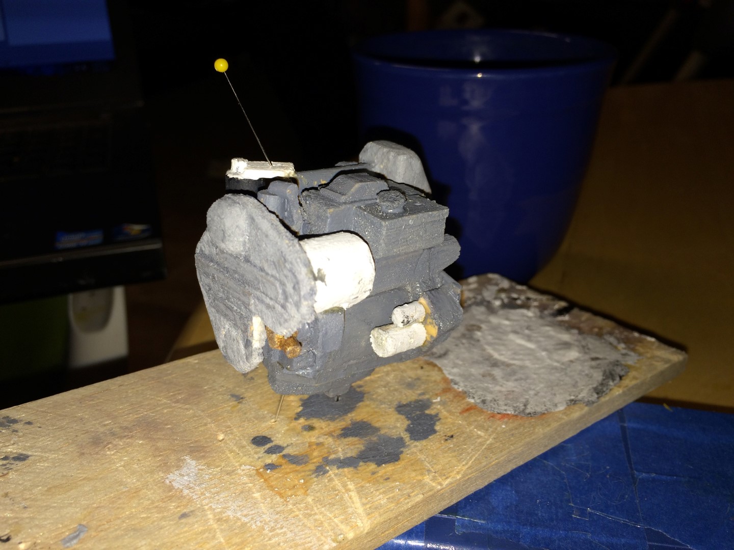
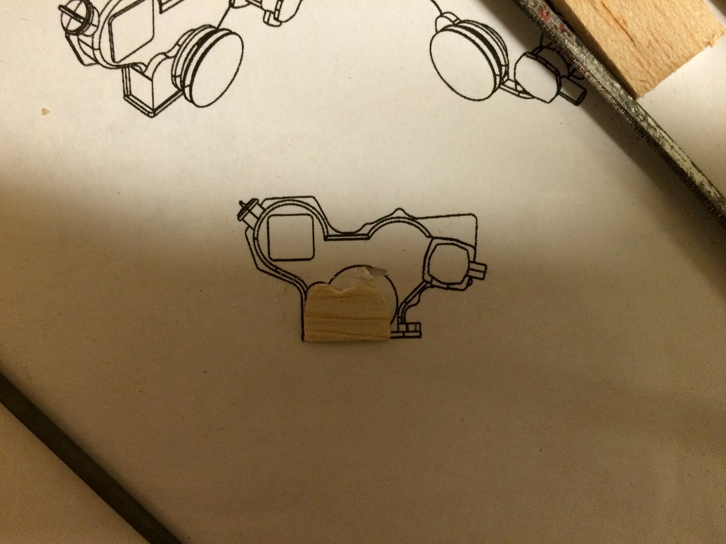
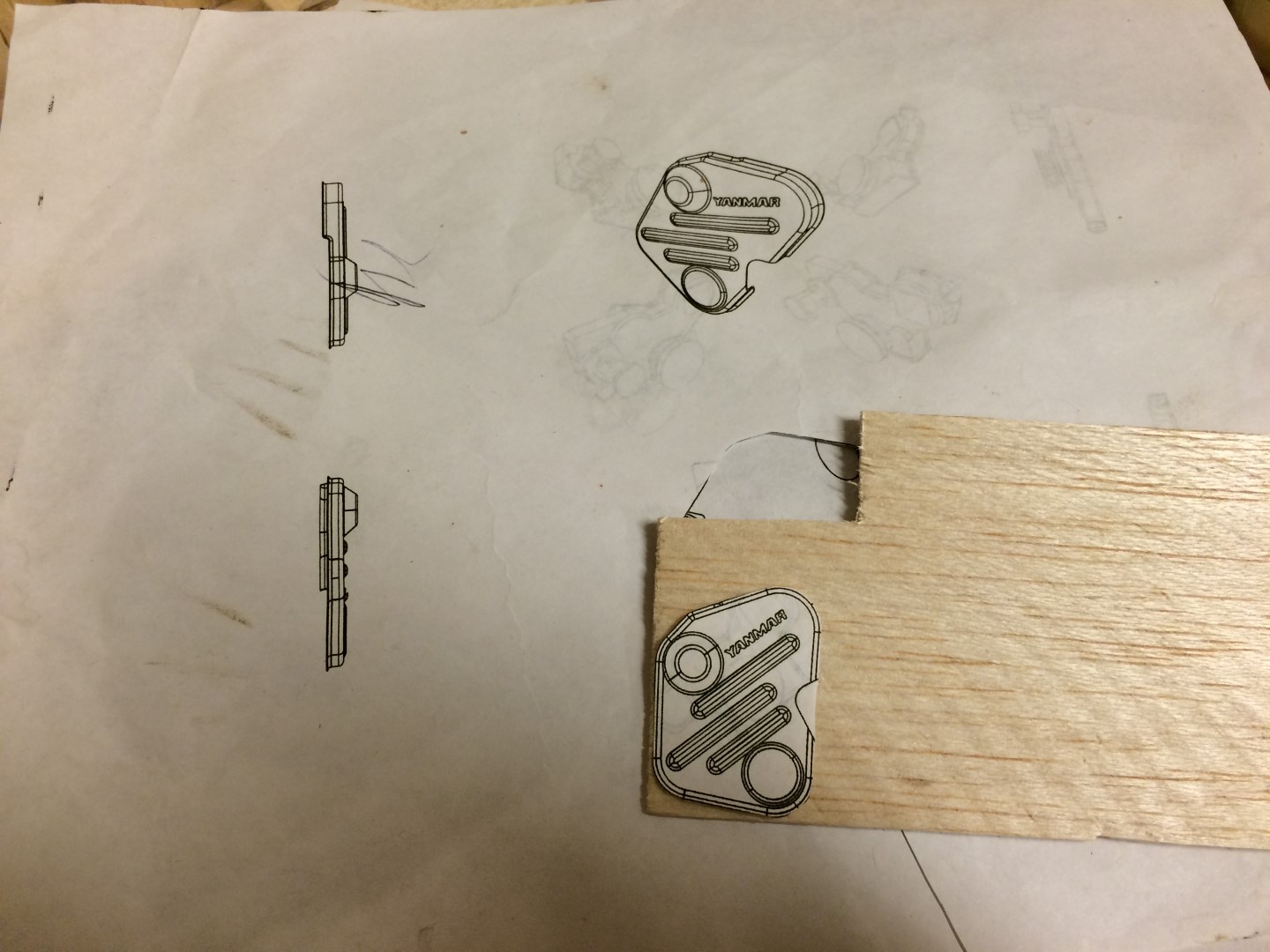
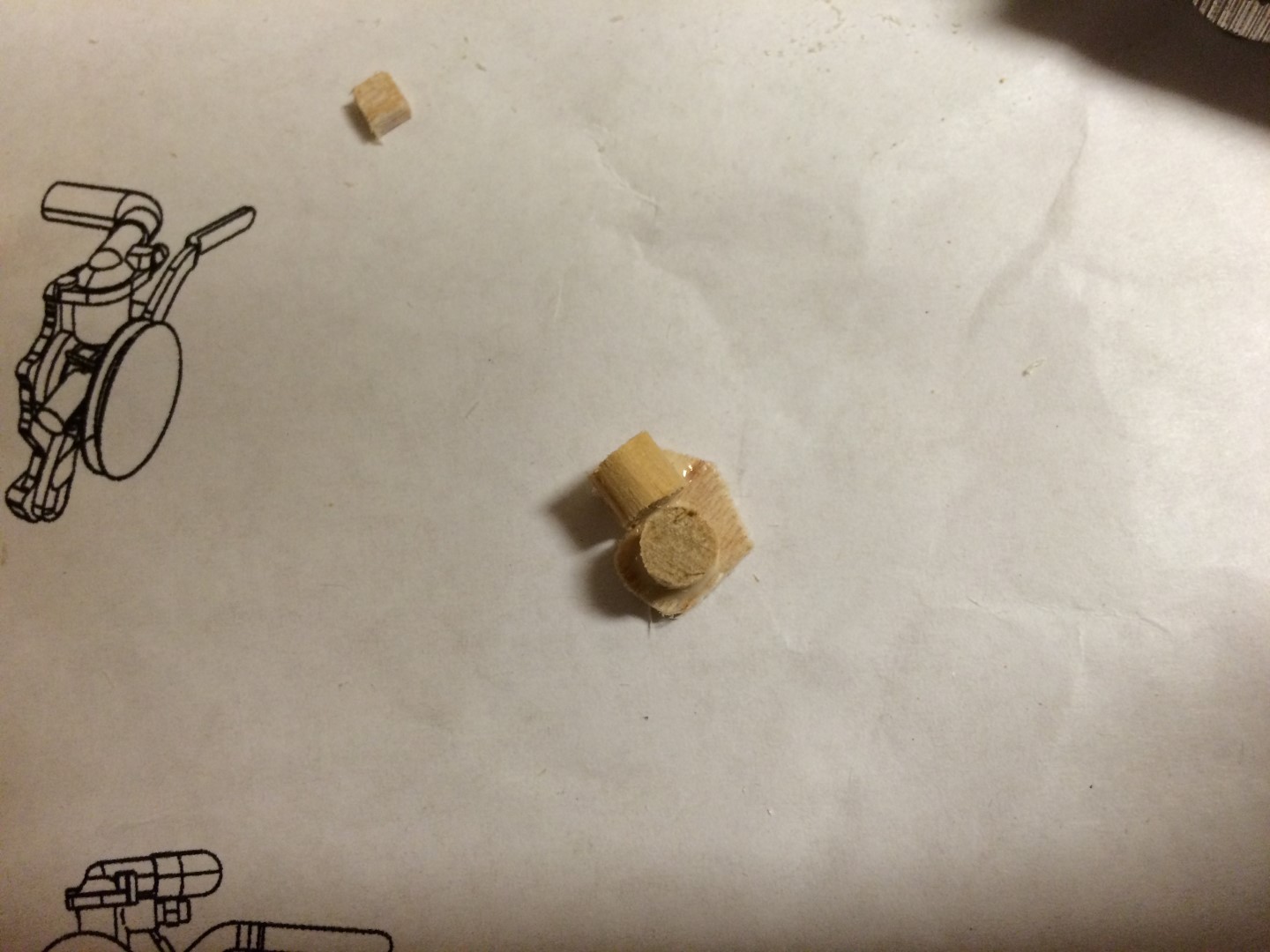
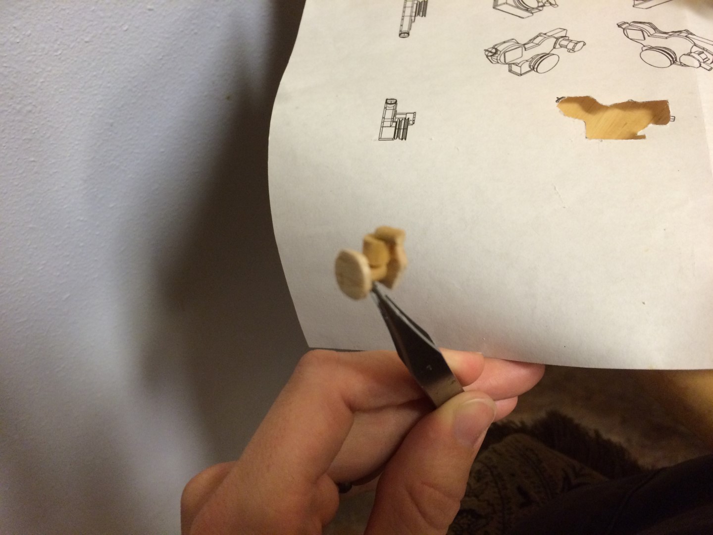
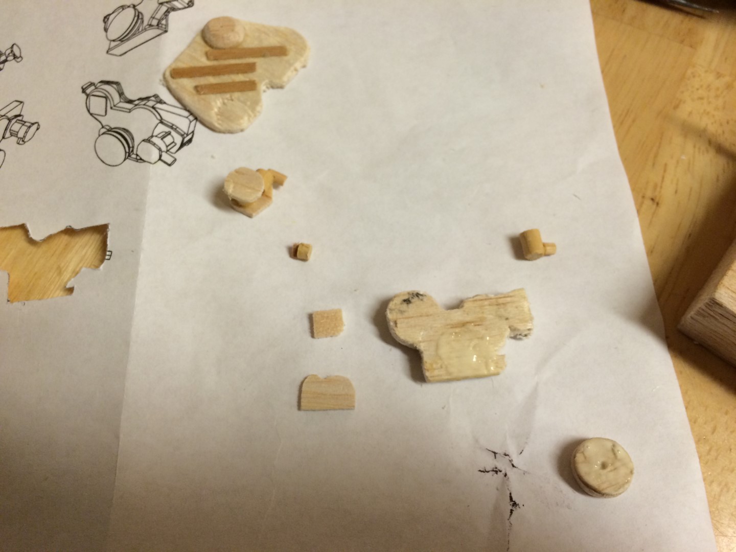
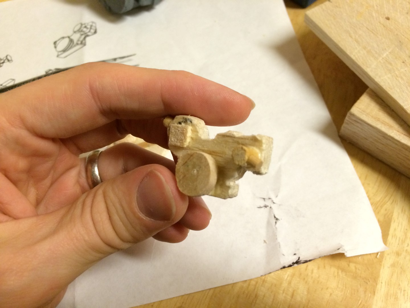
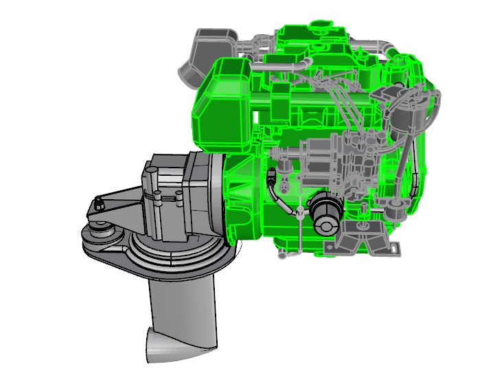
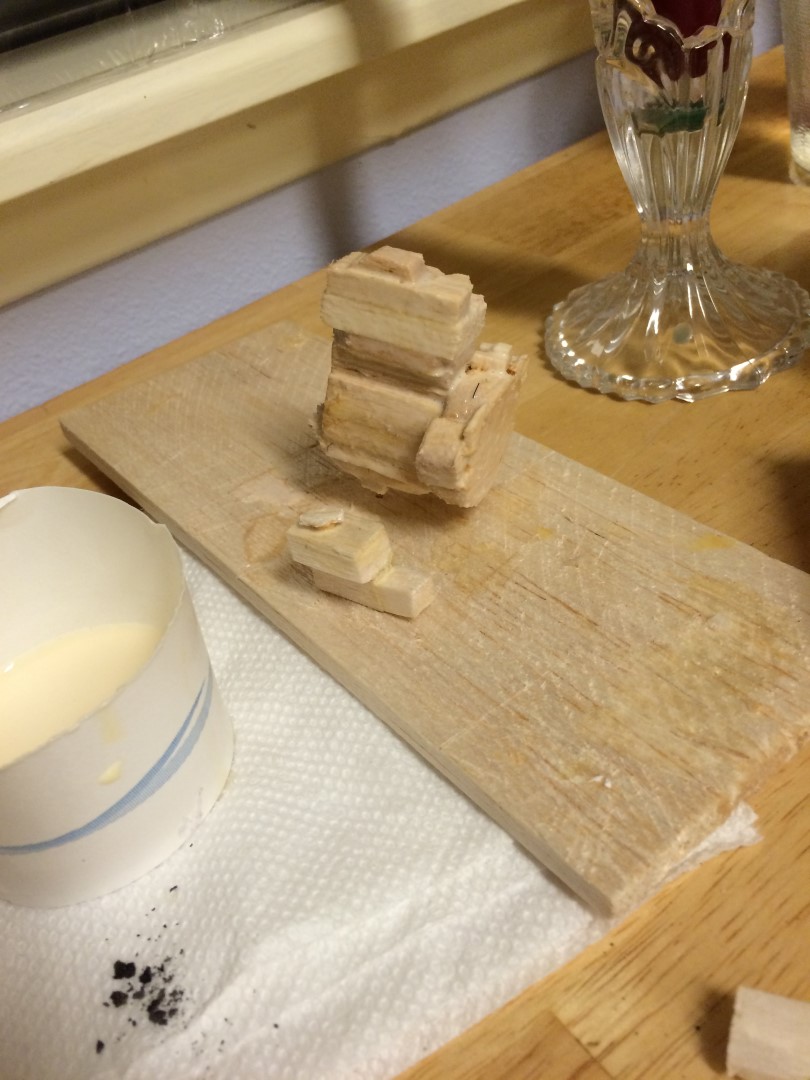
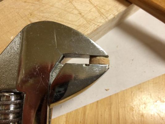
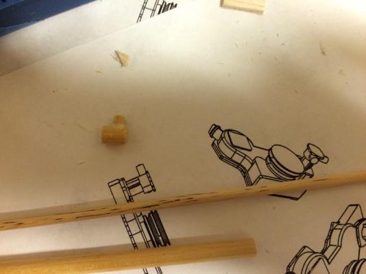
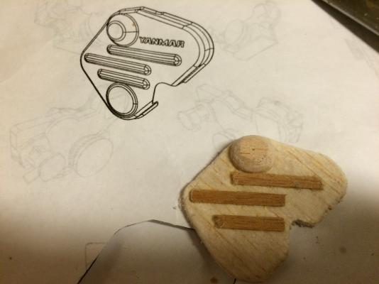
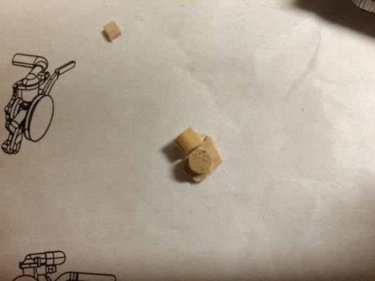
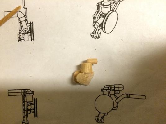
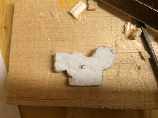
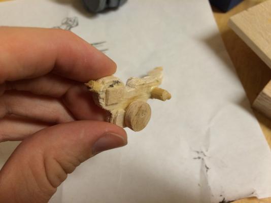
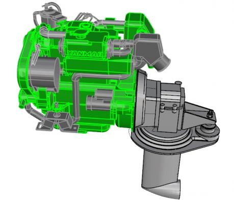
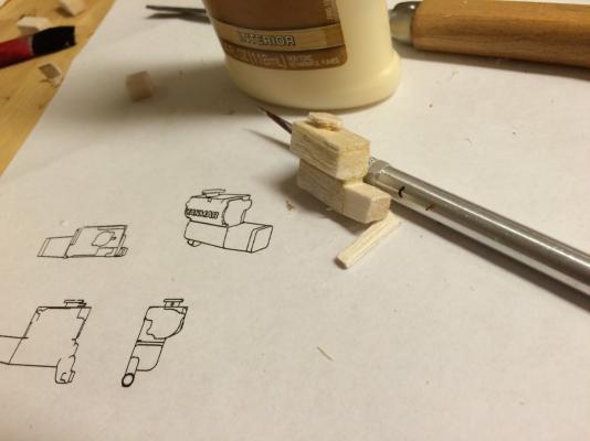
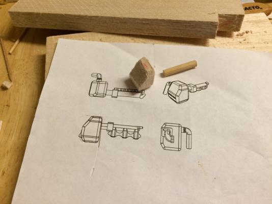
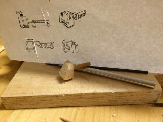
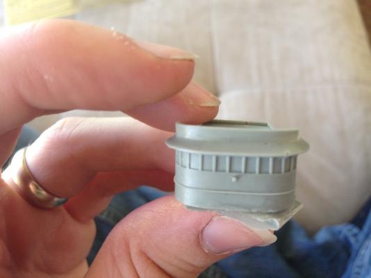
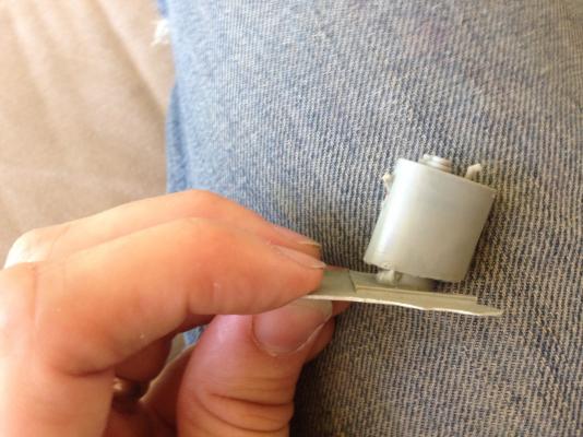
ENGINE FORWARD END This past weekend, I got most of the forward end of the engine made. I started with my 1:1 (model scale) print, but because of how complex the first part I wanted to make was, I added several more isometric views. Forward End Lower Part Drawing This component contains the seawater pump, main drive belt pulley, and some kind of reservoir with a fill cap. If I had started the whole build with this part, I probably would’ve quit – in fact, this is one of the parts I’ve been perplexed from the beginning on how in the world was I going to make that. Well, with a big chunk of the rest of the engine now made, I’ve gotten the hang of looking at the part and mentally breaking it down into sub parts made that I could then problem solve how to build. I’ve also gotten the hang of mentally deleting out the unnecessary details (such as small fittings, or the precise shape of a part that could be simulated with just a chunk of dowel). So, with that in mind, I took a look at the part and divided it up into chunks. The first was the mounting plate for the main pulley. This was one of the easier parts – just a small piece of balsa plank cut and filed to shape. Pulley Mounting Plate I should note that I actually intended to start with the main mounting plate (the piece that has what I’ll call Mickey Mouse ears). But, alas, for one of the few times in this build, I did NOT have a plank of balsa that matched the thickness of the part. So, I had to lay-up some pieces. I started by cutting a rectangle large enough to capture the whole piece, then cut my pieces of material, and glued them together. Up to this point in my life, I have not done much wood working, or really anything requiring an extensive set of tools. When I have had spare funds, they typically go to books – lots and lots of books – ranging from Star Wars novels to a many, many page tome called Philisophical Foundations for a Christian Worldview. And, a LOT of books about boats. In fact, most of the books I buy are about boats. I really like boats. Not sure if that was expressed Anyway, the point of that tangent was to explain why there is not a single wood clamp in my possession. Which presented a challenge with gluing two thin pieces of balsa wood together. I started by just using what I had – a book! (This one was a large volume covering the minute details of the design and construction of the Titanic.) I came up with a better solution a bit later, however... With my laid up part sitting under a book, and the mounting plate for the pulley cut, I moved on to the pulley itself next. Again, I didn’t have a piece of balsa the correct thickness. So, I cut two circles (ish), and glued them together. The part seemed too small to put under a book, but then I came up with my better idea. I didn’t have a wood clamp, but I did have an adjustable wrench! So, I took the pulley and compressed it in the wrench. Engineer's Wood Clamp With the pulley drying, I moved on to the seawater pump. This I simplified down to two pieces of dowel – one large, and one small. Luckily, I did have dowels that were close enough in diameter to the pump pieces, so I just had to cut them to length and glue them together. Seawater Pump Finally, I had the little fill pipe and cap for the reservoir-thing to make. A reasonable person would probably just cut a piece of dowel and call it good. I think at this point we’ve established that I am only partially reasonable, and that I have just enough crazy to be building a 1:12 scale model of an engine that will probably rarely be seen once put in the doll boat I’m making for my 2-1/2 year old daughter. So, I found a thin plank of wood (again, cannibalized from the Bounty model kit) and made the tab for the fill cap. Fill Cap/Evidence of Mental Instability At this point, the pulley part was dried enough to not come apart, so I took the laid up pieces for that big part out from under the book and clamped it in the wrench. Ended up working beautifully. With all the pieces for that first complex part made and/or drying, I moved on to the next big part – the belt cover. This was a fairly easy one, as I just needed to cut out the perimeter of the part from some balsa sheet that was the right thickness (no layup required here). Belt Cover-1 Then, I added some detail to the front. The strips were from the thin planking I stole from the Bounty, and the cone-ish shaped part on top was hand made by cutting a square and then filing. And filing. And filing. Belt Cover - 2 Now that part was done and drying, and I STILL had some time in the day, so I moved on to another complex part (at least at first look). This was the main coolant circulation pump, located at the top of the forward end of the engine. But again I broke it down into basic components – some flat parts for the mounting plate and pulley, and some dowel parts for the pump body, a filter of some type, and the discharge hose barb. Coolant Pump-1 Coolant Pump-2 Coolant Pump-3 When I came back to finish up the next day (having given everything overnight to dry fully), I started by cutting out the front view of the drawing and gluing it to the laid up rectangle. Then, I just cut around the edge, and filed into shape. Lower Mounting Block So, that done, I took a picture of everything I had made – the belt cover, coolant pump, and all the sub-parts to the lower assembly. Forward End Parts and Sub-Parts Then the fun part – gluing the lower assembly together. Once finished, I was REALLY happy – I think it captured the essence of the part spot-on. Lower Forward End Assembly - 1 Lower Forward End Assembly - 2 And, a picture of all the parts from this weekend together. Forward End Parts (2) Finally, I wanted to test my craftsmanship and see if the part would actually fit in the space left for it on the main assembly (as well as pre-visualize what it will look like). With some filing, everything is going to fit flush, and the size of the part is perfect for the little lip that was left for it. Again, really pleased with how this first scratch building adventure is progressing. Test Fit - 1 Test Fit - 2 Here is a rendering of the current state of the engine – everything in green is what I have made so far. The gray is what remains. Really getting into the final details now. Well, and the whole saildrive unit. Next time, I’ll probably make the alternator and starter motor. I may need to get some larger dowels, though. There are some parts remaining that dowel would be perfect for, but they are too large in diameter for what I have on hand. Probably won't get to that for a couple weeks, though - this Saturday we are all flying to the East Coast to visit family for two weeks. My wife and I both grew up in Northeast Pennsylvania, so both our families are there, which makes visiting everyone easy - they all live within a ten mile radius of each other!


-
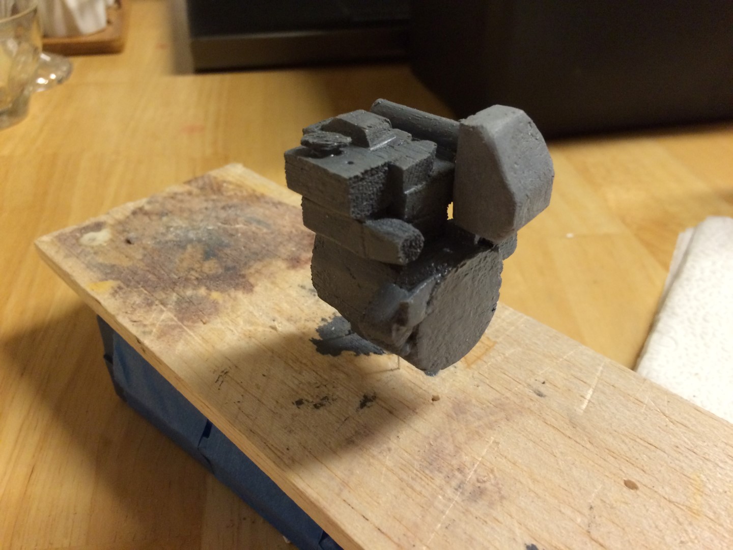
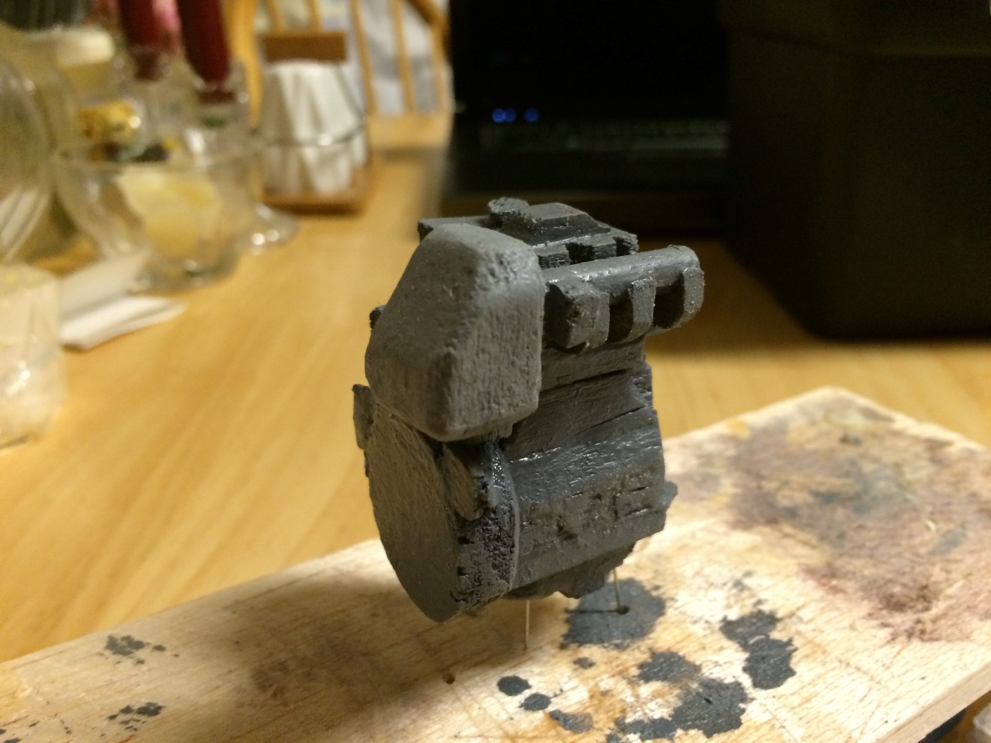
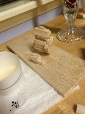
Aaaaaaannnnnnndddd I'm back! It's felt like a long, long time since I've been able to do anything other than think about getting back to work. But now, with garden projects out of the way, and the new baby getting into a routine, and the rains of Seattle descending upon us, I'm finding moments to get back to work on this project, and finally I think it may be a regular occurrence - at least until spring comes and it's time to prepare the ground and sow seeds for the summer season. Woohoo! So, without further delay: ENGINE CONSTRUCTION CONTINUED - COOLANT HEAT EXCHANGER So, a long, long time ago (but in this galaxy), I was building a small balsa wood representation of the auxiliary engine for the sailboat. I left off having made the main block, the cylinder heads, lube oil sump, and flywheel housing. The next step was going to be to coat the assembly in a 50/50 water/wood glue mixture (per advice from Mark from like eons ago) to help seal it, and then construct the coolant heat exchanger. Well, I FINALLY did that. Coating Engine Assembly with 50/50 Mixture While I waited for the coating to dry, I started work on the coolant heat exchanger. I started the way I have done all the pieces so far - with a printout of the part in model scale to work from. Then, I start picking from my grab-bag of balsa strips and planks and chunks to find a piece that will work for the size of the part I'm making. So far, I've been really lucky that most of the pieces somehow match thickness and width of my planks, so I just need to cut to the length I need. First Part of the Heat Exchanger From the base part, I just kept eyeballing and trimming pieces, building up the part. I made this assembly in three main parts - the narrow bottom, the wider top, and the kind of extension thing that has a bit of shape to it. I glued the pieces together, and then coated the assembly with the 50/50 mix right away, since it was already mixed up. As I looked at it, I realized it didn't quite 'pop' enough. So, I looked at my original picture again, and realized I hadn't made a fill cap. So, I found a dowel that seemed exactly the right diameter (again, stroke of luck), and then made the cap from the thinnest sheet of balsa I had, cut to a diamond shape to give the illusion of a round cap with ears on two ends. Assembled Heat Exchanger Heat Exchanger Next to Engine Assembly AIR INTAKE MANIFOLD The next thing I worked on was the air intake manifold. This was an interesting assembly, because it (1) required carving an interesting, kind of complex shape, (2) required, for the first time in the build, a length of dowel which (3) had pieces that were VERY small and needed to be faired into the dowel. Needless to say, I had to think about this one a little bit. (As an aside, I think that listening to the audiobook version of Andy Weir's The Martian while putting this part together may have had a subliminal effect at making me a better problem solver.... Excellent book made into an excellent movie.) Anyway, I started with the 'blocky part' (air cooler?) by finding a balsa chunk with a thickness that matched at least one dimension of the part (either width, length, or depth) so I would only have to cut it to the size of the other two dimensions. Again, I was able to find a piece that was basically spot on. I can't remember which dimension it matched, but it matched it pretty perfectly. I trimmed a chunk out, so I had a block of the same overall length, width, and height of the part I needed to make. Then, I started shaving it down to the best of my ability to match the complex shape of this part. Next, I (again) found a dowel that was nearly spot-on to the diameter of the pipe part of the assembly. So, I just cut it to length. First Air Intake Manifold Pieces. I used a round file and the tip of an Exacto knife to make a circular depression in the back of the blocky piece, inserted the pipe, and glued. Pieces Glued Together The following picture is me 'test fitting' the new parts to verify everything was going together right. Test Fit of New Assemblies While carving the blocky part, I noticed that I had taken a small chunk out of the bottom of the piece. Voice #1 said 'It's at the bottom of a part on the back of the engine, in a 1:12 scale boat, in a compartment that almost no one will see. Just let it go.' Voice #2 said 'Yeah, but it would be WRONG.' (Voice #3 said 'You should probably see someone about these voices in your head). Voice #2 prevailed. I applied some Milliput to the part, and smoothed it out to fill the part, and provide a moldable, file-able coating that I could use to refine the shape once it dried. Since at this point (I believe this was the next work session) the water/glue coating on the other assemblies had dried, I filed, sanded, and painted them. I based the color on some pictures I found of the engine. The color is probably a bit dark, but it was the only shade of gray I had. I'm not too concerned. Air Intake with Milliput Applied, and Painted Engine Assembly and Heat Exchanger The last thing I did was coat the dowel with the 50/50 mix, since the dowel was a different type of wood and I had some trouble getting the balsa to stick to it. (It came from an HMS Bounty POF kit I bought in high school that was WAY above my skill level, that I decided would forever remain incomplete as a reminder to appropriately assess my abilities, and that I have since cannibalized for wood.) The next work session, I focused on the intricate details, cutting the three small intake ducts out of a strip of balsa. I then used a round file to try to open the tops up to fit on the dowel. I left a bit of thickness on the outside of the dowel to allow shaving down once everything was set and dry. I very (very) carefully glued the pieces on, then let it dry. Air Intake Manifold Assembly I sanded/shaped the dried milliput on the blocky part, sanded down the air intake ducts so they were curved on the bottom and faired flush to the dowel, and then painted the part. In pictures of the real engine, it appeared the blocky part was a lighter gray, so I mixed some white into the gray for painting that piece. The final result is more distinguished on the model than in the pictures of it; it's hard to see the tone change in the pictures. Air Intake Painted; Heat Exchanger Glued to Engine Assembly And finally, I added all the pieces to the engine assembly. Engine Assembly to Date, Looking Forward Starboard. Engine Assembly to Date, Looking Forward Port At this point, I'm very pleased with how it looks. Sure, it looks like painted wood and not metal, but in this case Voice #1 is winning - it's not often going to be seen, and when it does get seen, it will have the essence of an auxiliary engine, which is what I'm shooting for. It already gives off the essence of an engine, and I still have loads of detail to add. I think by the time I have fuel lines and water hoses and the like added, it won't matter so much that you can see some of the wood grain. Hope to have another update in the near future. I haven't decided yet what I'm going to tackle next - probably some of the complex components on the free end - the stuff driven by the belts (SW pump, Alternator, Coolant Pump, Etc).


-
Add my prayers for a speedy recovery to the docket as well! So sorry to hear - I've only had to ride an ambulance once. It was a scary experience - and I wasn't even the patient in need! Hope all is well soon.
-
Looking good! I think you've captured the essence of the hull form suggestions. She looks really streamlined!
-
That looks a lot better! there may need to be a touch more fairing into the bulb, but then again, at the scale you're working with the practicality/possibility of that may be low, and the overall effect may be minimal to what you're aiming for. So, I'd say you've got it down! Looks really great.
-
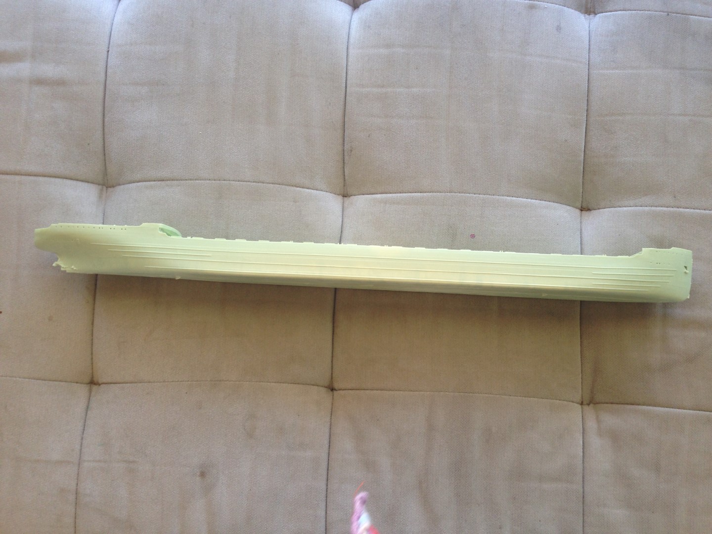
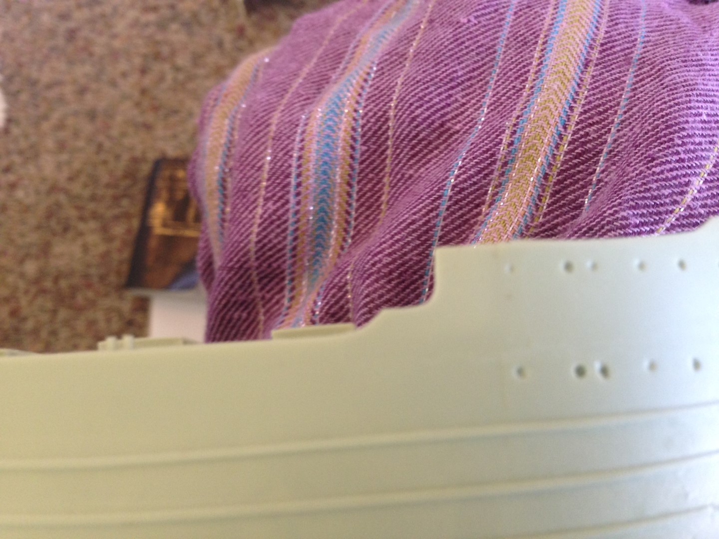
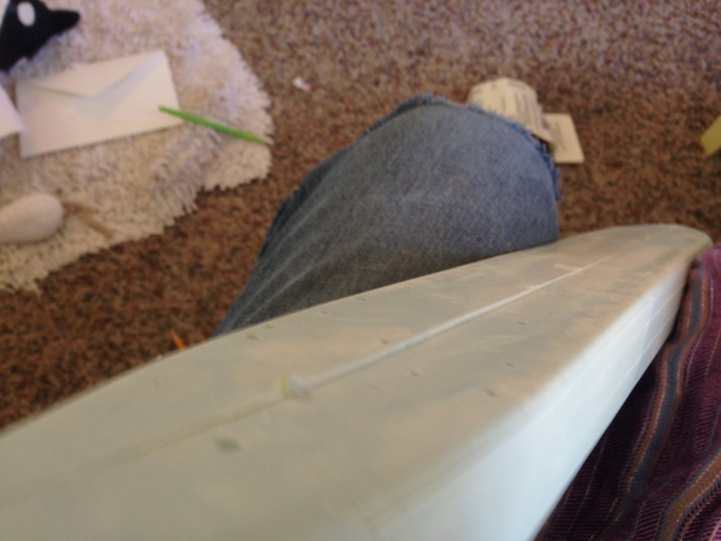
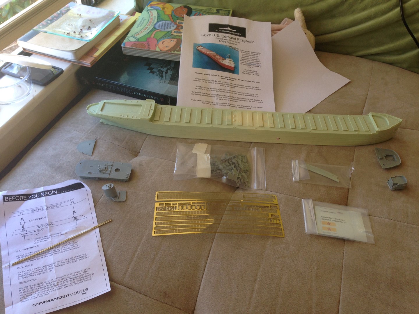
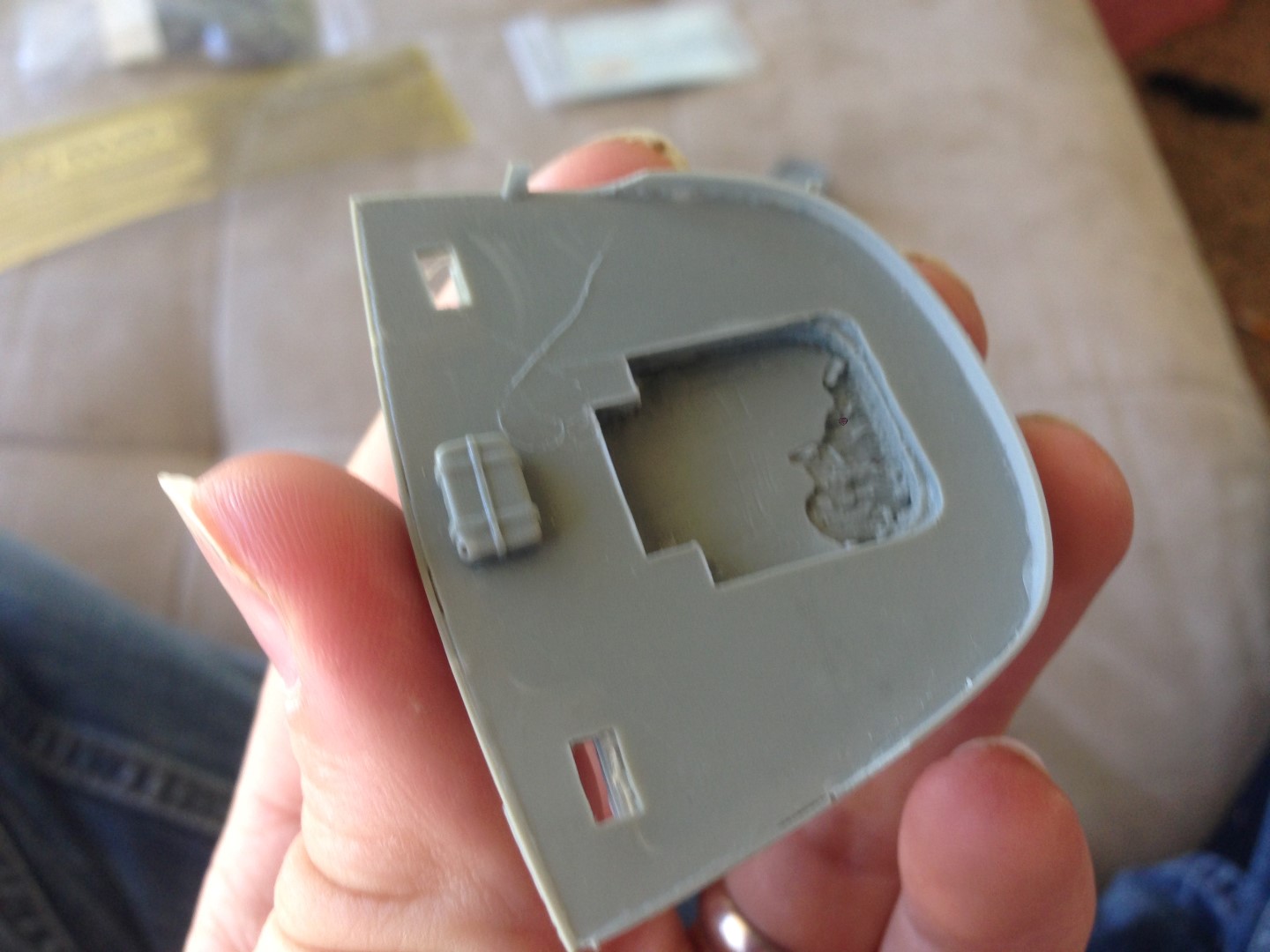
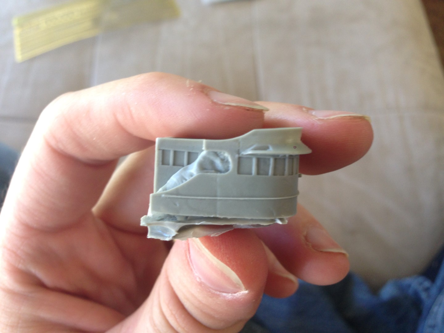
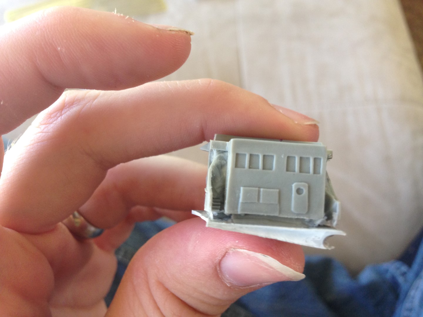
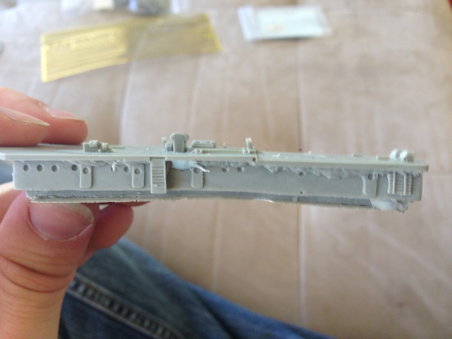
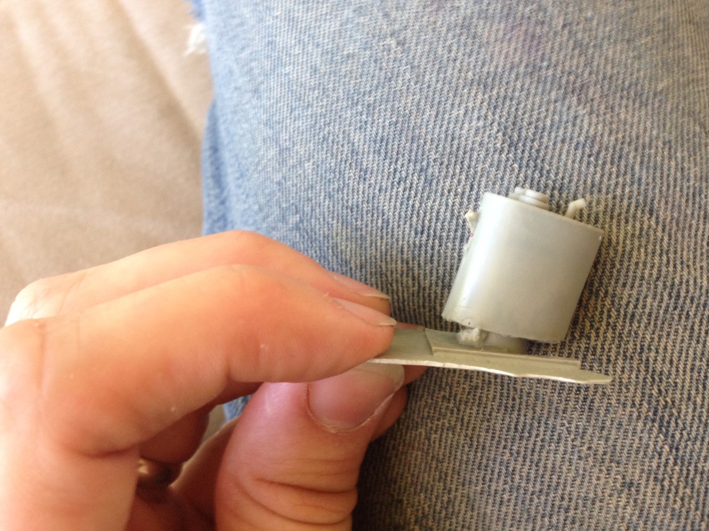
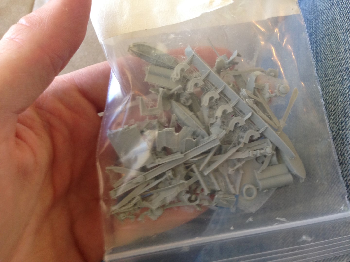
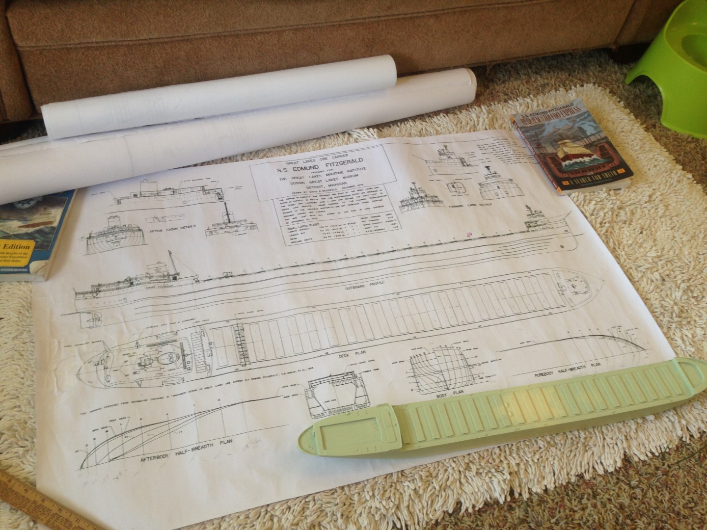
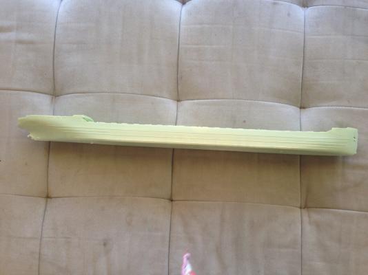
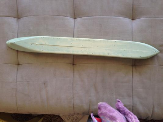
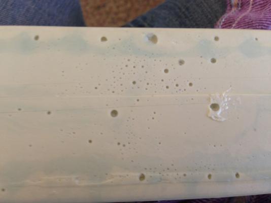
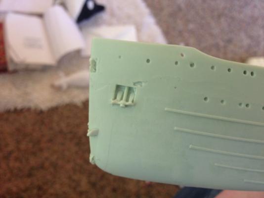
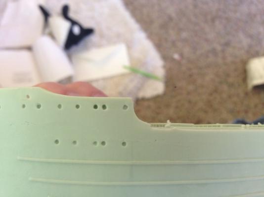
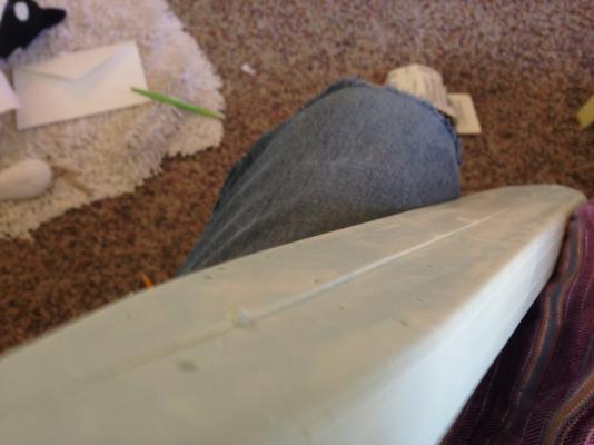
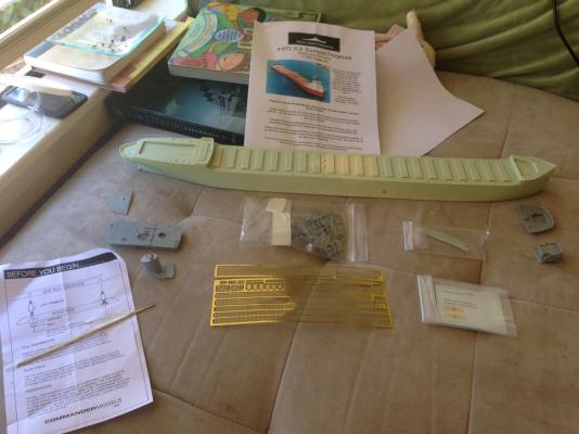
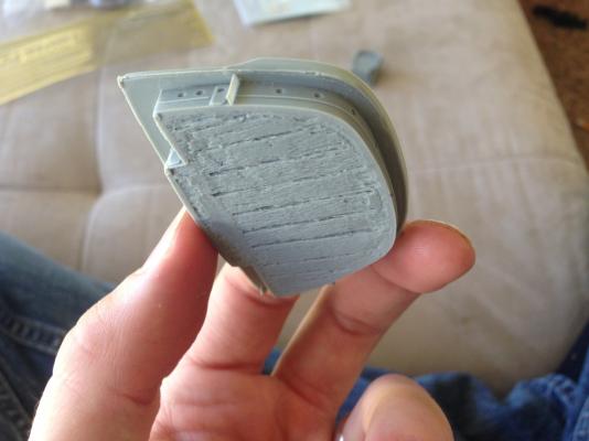
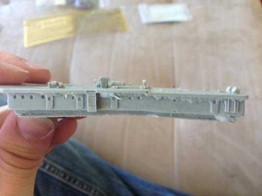
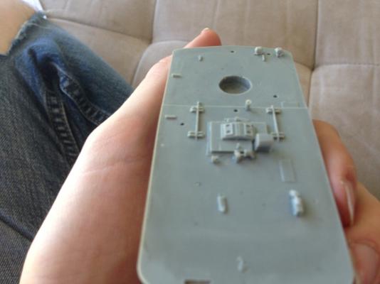
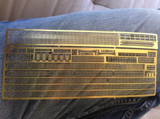
1957 The United States is an industrial nation, with manufacturing factories still booming after the immense growth in capabilities and newfound prosperity following the Second World War. Every part of the country plays a role, from iron mines in the North Mid West, to the steel mills of Pittsburgh and the automotive plants in Michigan; from the forests of the Northwest to the ever expanding suburbs across the country; from the agricultural 'breadbasket' of the midwest to new, all encompassing 'Super Markets' in every town. And in the heart of the country, facilitating much of the movement of the raw materials that keep the country running and working, are the shipping lanes of the Great Lakes. Maritime culture is deeply rooted in the towns around the Lakes and the families that live in them. Many families are made up of generations of lake sailors. The Fitzgerald family is one of them, with a rich history of Lake mariners, including several Skippers, at least one of whom has had a lake boat named for him. While Edmund isn't a mariner (instead being president of Northwest Mutual Life insurance company), he is proud of his family's maritime heritage, and so Northwest Mutual Life decides to make an investment - the funding of a Lake freighter, larger than any that has been built up to that time. At 729 feet (222 meters) long and 75 feet (22.9 meters) wide, it will fit juuuuuuust inside the restrictions of the newest lock in the Sault Ste Marie (aka Soo) Locks connecting Lake Superior with Lake Huron (and thereby connecting the iron mines in the north with the industrial powerhouses of Chicago, Detroit, and Pittsburgh in the south). Northwest Mutual signs a contract with Great Lakes Engineering works in Detroit, Michigan to build the freighter, which will be hull no. 301. As the soon-to-be largest boat on the Lakes, however, much of the local public learns of her by a different name. She will be called the SS Edmund Fitzgerald, honoring the president of Northwest Mutual Life, and the maritime heritage of his family. Build Log - Part 1 Kit Review As the first 'official' post in this log, I want to do a summary of the contents of the kit, as well as some of the immediate challenges I see. First, an overview shot: The parts are pretty straight forward. There is a solid chunk of resin that is the main hull, a couple smaller deckhouses that make up the forward superstructure, a deckhouse that is the aft superstructure, and the funnel. There is a bag of small fiddly bits for bollards, winches, boats, vents, etc., some brass rod to make the masts, and an extensive set of photoetch pieces for things like railings, the hatch removal and replacement crane, and the radars. There is also a decal set. There are some VERY basic instructions, mostly hand written. The kit manufacturer is a small outfit, it seems. There are some significant quality issues with the major pieces, so it seems most of the time on this kit will be fixing and prepping the pieces. Starting with the hull: Looks OK in profile, but.... One, the hull has a little bit of a banana shape. Not super noticable, so I don't think I'll bother trying to correct it. The larger issue is all the little holes. A close up shot it below: These will all need to be filled and the whole bottom smoothed out. Additionally, there is a ridge where the mold seems to have come out of alignment: Not sure what I'm going to do about that. Looking at the bow, there is some minor cleanup here, but the details of the anchor and portholes seems pretty good. Unfortunately, the port side bulwark is damaged. It should look like this: But, it looks like this: Haven't figured out how to fix that one yet, either. Moving on to the forward deck house: The top side has a recess to accept the Pilot House above it. There is a recess in the hull to accept this deck, and one aft to accept the aft deck house. So, all these parts eventually have to nest together to form one cohesive unit. The underside is.... interesting. Not sure if/how much of this will need to get cleaned up. The Pilot House is a real mess. I've entertained notions of rebuilding it from scratch using polystyrene, such that the windows are 'see through' and I can create the essence of the interior of the pilot house. Maybe..... The aft deckhouse is pretty messy too, and has some shape to it. Not sure yet if this follows the hull, or if it's just bent out of whack. If it's the latter, another issue I don't even know how to begin to correct. The funnel is pretty clean Finally, the bag of 'loose parts'... ... and the photo etch sheet. As I mentioned, the instructions are lacking in detail. Fortunately, I happened to have needed a lot of information on the Fitz when doing my thesis work, so I was able to procure (from the library at Bowling Green State University in Ohio) copies of some of the original builder's drawings of the boat, as well as a 1 sheet drawing that someone made to aid with constructing a scratch built model, showing the details important for a replica, but not as many details as on the construction drawings I have available to me. So, I have a LOT of information to fill in the gaps in the instructions. The only downside to the construction drawings is they are just that - drawings showing the boat at her delivery in 1958. There weren't a lot of changes between then and 1975, but there were some. Well, that's the kit. Not sure when I'll do anything other than stare at it and scratch my head, but once I do you'll hear about it!


- 40 replies
-
- 8
-
-
- edmund fitzgerald
- iron shipwrights
- (and 1 more)
-
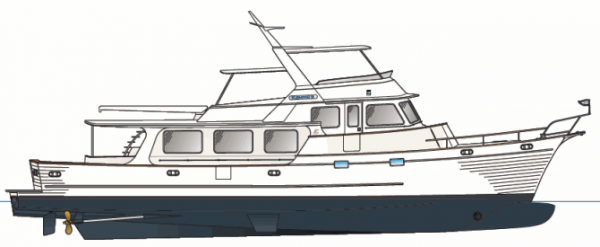
Not a problem at all! And, if you ever have a specific question, or something you want me to look at, always feel free to send me a PM or ask in your post, etc. I absolutely love sharing anything I have knowledge on as much as I love learning new things. It's never a burden to me. I found an image I remember seeing that led to my comments on the hull - it is attached below: I grabbed it from here: http://www.flemingyachts.com/78layouts.html It's a 78 foot boat, but the hull form (at least below waterline) appears to be what you are shooting for. In the profile picture, if you can see the line drawn out for the chine (it runs right above the prop from the transom to a bit forward of midship), see how it rises forward, then 'disappears' into the hull. As it rises, it's also softening, such that where it disappears is where the hull is completely faired all the way down to where the bulb starts to reverse the curve of the stations. On the link, if you look at the one plan view for the lowest decks, you can see how the bow gets quite narrow below waterline forward of midship, meaning the boat has a lot of bow flare forward, with a smooth entry faired into the bulb. Hopefully this helps illustrate the concept I was trying to express. Looking forward to seeing what you come up with!
-
Looking good Patrick! Only one Nav Arch suggestion for the hull. I would soften the chine (the 'corner') in the hull forward of amidship, so that by the time you get to where the bulb starts, the bulb fairs smoothly into the rest of the hull with little to no discernible chine. The entry will be finer, meaning the bulb will actually be efficient - as it is now, the bulb would generate a bow wave that would smack right into the abrupt shape change leading to the chine, and so it seems to me that it wouldn't do anything, hence the idea that the shape should be finer forward that what you have shown. (The intent of a bulb is to generate a bow wave that interferes with the bow wave generated by the stem proper, such that the two waves cancel out and less energy is transferred into the water.) The other item that leads me to think the underwater hull forward is too severe is that the bow thruster is a bit aft of the bulb; with the hull as you have it shaped, the tunnel would be very wide, and the opening would be at a very strange angle, such that there would be a very elliptical opening. But if you make the hull a little finer, that should pull the side a little closer to vertical and reduce the width of the tunnel and also improve the opening in the side to be more circular. But other than that one suggestion, I think you have the hull spot-on to what I've seen of hull models used for tank testing. Keep up the good work! Ben
-
Congratulations on completing the build! She's lovely - a fine addition to your already magnificent fleet. Good job, and itching to see 'keel laying' for the next one.
-
Dan, I wouldn't change a thing! It has enough detail to get the essence of what needs to be represented, and it is done well. Looking forward to the next update!
- 108 replies
-
- 2
-
-
- andrea doria
- ocean liner
- (and 1 more)
-
Looking really awesome! I may be able to help with one of your points of intrigue: The large diameter pipe is the main exhaust from the propulsion boilers; the small diameter pipes are the exhausts from auxiliary equipment (diesel electricity generators, etc). The 'block' structure is simply the casing enclosing the mufflers for these exhausts, and some of the other fairings are probably a mixture of aesthetic 'boundaries' within the structure, to hide the guts from being seen through the vents in the shell, as well as air catches, to ensure the exhaust is blown up and away from the deck (this may well be what the large vents are for - to direct air into the funnel and then scoop it up so it pulls the exhaust gasses with it, ensuring the decks are clear.) Incorporating this type of feature into the funnel is common - the unique design of the Queen Mary 2's funnel is primarily due to the need for an air scoop to blow the exhaust up and away from the deck, since the funnel itself was height-limited by the ability of the ship to pass under the Verrazano Narrows Bridge entering New York at high tide.
- 108 replies
-
- 8
-
-
- andrea doria
- ocean liner
- (and 1 more)
-
Just saw you started a new log! Definitely on board, again. The concept for this 'small' (in mega yacht standards!) motor yacht reminds me of a design I did with a team of classmates my junior year of a ~150 ft (45m) motor yacht. We only did very preliminary/concept design, but enough to do some basic arrangements and naval architecture work (weight/stability/powering, etc). I'll have to see if I can dig something up on it from my files. I have hard copies of the drawings, but I think the original cad files are lost to the abyss....