HOLIDAY DONATION DRIVE - SUPPORT MSW - DO YOUR PART TO KEEP THIS GREAT FORUM GOING! (Only 51 donations so far out of 49,000 members - C'mon guys!)
×


BenF89
-
Posts
316 -
Joined
-
Last visited
Content Type
Profiles
Forums
Gallery
Events
Everything posted by BenF89
-
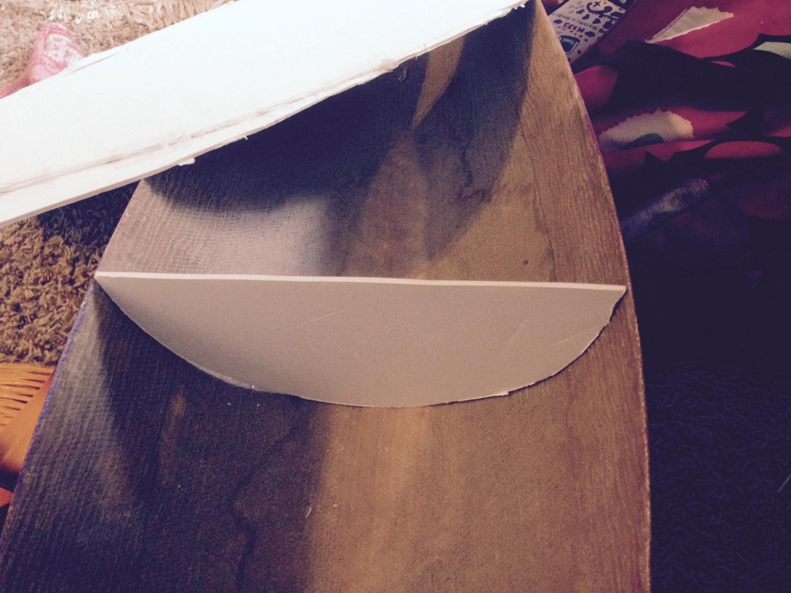
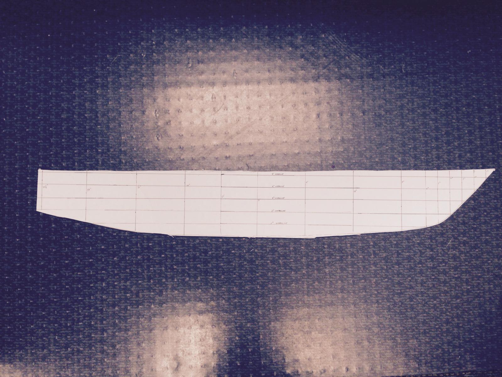
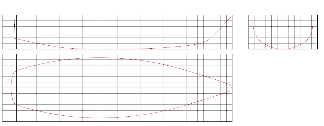
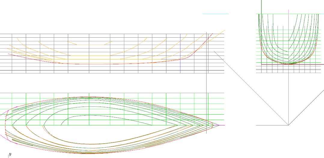
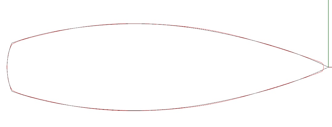
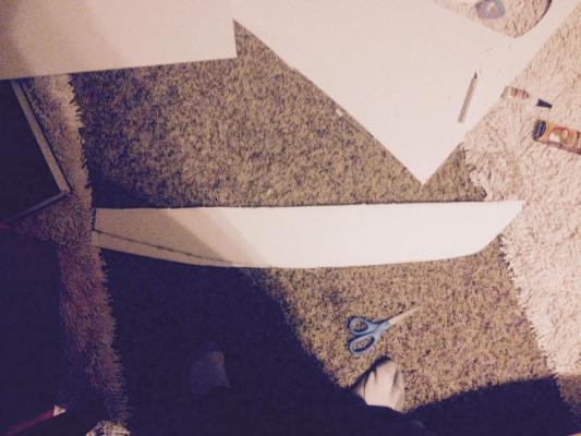
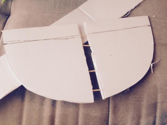
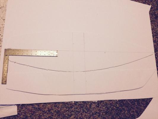
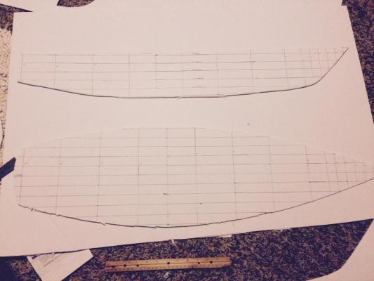
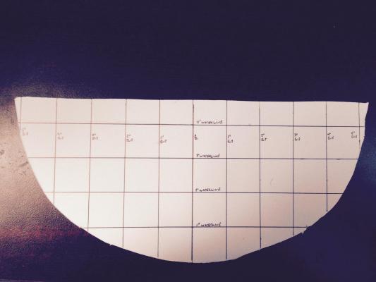
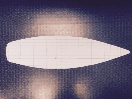
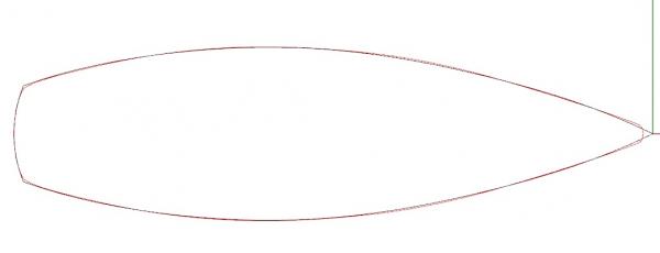
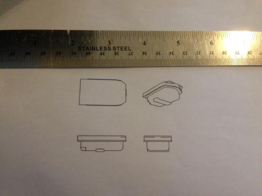
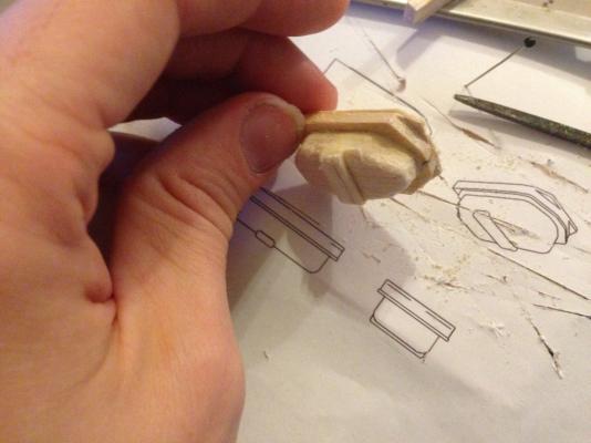
 THE HULL LINES STRIKE BACK Er, rather, I strike back at the hull lines. I spent quite a while not doing much of anything with this project as we had (have) a laundry list of outdoor work items we've been trying to accomplish before the next baby shows up, which will be any day now at this point. So I've been busy outdoors. That, and we've spent several weekends going into Seattle and enjoying being able to get out of the house before we are holed up again for a few months adjusting to a newborn again. That said, on our latest excursion to Seattle, I stopped by an art supply shop looking for duck weights and splines, with a grand idea of eventually getting back to doing lines by hand. However, they didn't have any. But I did walk out with a very basic set of french curves, and two large pieces of foam board with a vague idea that they may help me in my issues with trying to get the hull shape right (since at that point I didn't trust the lines I had been developing, because of the scaling issues I was running into). After a little staring at the pieces, and thinking, I started by placing the hull upside down on one of the pieces, and tracing around the sheer line. At first I figured this would be a starting point for just templating the deck at the level I wanted, but I couldn't figure out how to move from a piece of foam board the shape of the sheer line to a deck level within the hull, without some other point of reference. So, I laid the hull on it's side and sort of traced the profile. I say sort of, because it was much less straightforward than the sheer line. But I had enough marks to take a go at cutting out a piece of board, and then starting to hack away at it until it fit snugly in the centerplane of the model. The first two pieces are shown in the below image. Initial Template Pieces I ended up trimming too much off the aft end, so I jury rigged a filler piece onto it using toothpick 'dowels' and scotch tape, and then trimming that down to shape. Jury-Rigged Profile Template By this point I realized I would need a midship section, as well. So I trimmed a half-station to shape, then traced it onto another piece. However, I had cut the half to just less than half-beam, meaning there was a gap in the middle. So I got some more tooth pick dowels to hold the two parts together. Jury-Rigged Midship Template Not satisfied with the jury-rigged midship template, I just traced the whole thing onto another piece and test fit it in the boat. It fits pretty tightly, with not too much error from the actual surface. New Midship Template in Hull (I ended up doing the same with the jury-rigged profile template a little later in the process) At this point the vague idea sprung into clarity - I could use these three templates as scale-checkers for the hull lines! So, I started to lay out a grid, holding things as lined up and square as possible to enable using them as background images to trace over, then scale the tracing to match the actual spacings of the grid. Laying Out the Grid on the Profile and Plan Templates I settled on a nominal 4" station spacing, with 1/4 stations forward, and a variable spacing around the max section and the after perpendicular. I also used 1" spacings for buttock lines and waterlines. Grid Laid Out on Templates Once that was complete, I added the grid to the midship section. Midship Section Template And, for good measure, the rest of the images I used to trace over, holding the camera as square to the pieces as I could: Plan Template Profile Template Once I traced the templates, including the grid, I did the necessary rotating (to ensure the lines were truly horizontal and vertical) and scaling so everything lined up. There was a little distortion towards the end of the pictures, but I made due as best I could - the template was at least two dimensions, so I didn't have spacial distortion like with side-shots of the model itself. Below is the tracings of the templates, aligned and ready to import into the actual hull lines drawing. Traced Template Lines And, finally, the current state of the hull lines. The red lines are the tracings of the templates. Adjusted Lines Drawing The issue was longitudinal scale - the vertical scale matched up nicely with both the profile and midship templates, and the width of the plan and section views was correct. The problem was with the longitudinal scaling of the profile and plan views, which was fairly easy to correct. The additional advantage is that I now have a pretty good centerline profile, and I have the sheer line in plan view - two things I would have had to guess at if I had stuck with just the points I measured. Finally, to satisfy my curiosity, I copied the tracing of the plan view template into the 3D design model, to see how close my eyeball-based guesstimation of the hull shape was, at least at the deck. I was pretty pleased. Black is the outline of the 3D model, red is the template taken off the actual boat. Shape Check of 3D Model Next step will be to finish fairing, now that I have the scale right, and fairly decent templates of the governing shapes in all three views.
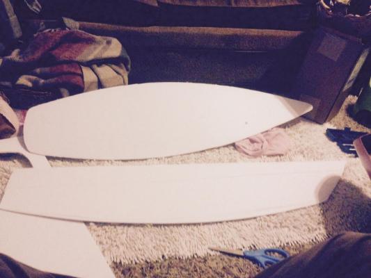


-
'persevere' - you were only off by two letters. synonyms: persist, continue, carry on, go on, keep on, keep going, struggle on, hammer away, be persistent, be determined, see/follow something through, keep at it, press on/ahead, not take no for an answer, be tenacious, stand one's ground, stand fast/firm, hold on, go the distance, stay the course, plod on, stop at nothing, leave no stone unturned; Sounds like the right word! I'm watching your progress on the P.E. intently; I've never used it before, but my next kit project relies on it for a complete model (as opposed to some kits where it is an optional improvement). The base kit is resin, through, instead of polystyrene. So I think nearly everything will need to use either epoxy or CA glue.
-
Anytime! I love talking about this ship and providing any information I know. However, if you are looking for really good information on making the ship reasonably accurate, or trying to get ideas for how to tweak things, etc, I would really recommend one of the books I mentioned - "RMS Titanic: A Modelmaker's Manual". It's 150 pages, and goes step-by-step through the author's construction of his own 18 FOOT long model of the ship (!). He incorporates tons of detail in the model that may be over the top in 1:350 scale, but the book is chock full of photos of the Titanic and her sisters, along with detailed drawings of really anything visible from the outside - superstructure side wall elevations, deck plans, vent details, etc. It's a really great book - especially if you want to go on to do a larger scale model like you were talking about. It would be well worth the small investment. Not to discount the other book - Titanic The Ship Magnificent. But that is an extensive two volume set that has details about the ship that I didn't even consider wanting to know about! It's a great set if you're a Titanic junkie. The first volume is Design and Construction, and has all the engineering details one could ask for; the second volume is Fitting Out, and goes deck-by-deck through all the details of how the ship was furnished, down to details of how they assembled joinery bulkheads and beds, or the assortment of soap dishes that were used for the second class cabins, or the types of fancy toilet paper holders in the various themed First Class staterooms! It's a bit of an investment, though, and is almost TOO much information if you're not a gung-ho Titanic enthusiast. I think I barely qualify, and as such, there are still whole chapters I haven't even looked at yet - and I've had it for over 5 years.
-
Wow! The beauty of the boat is really accentuated by the sole and the deck, at least for me. Maybe it's just the sense of scale they now provide that demonstrates how pretty that boat is, but either way, now I want one even more!
-
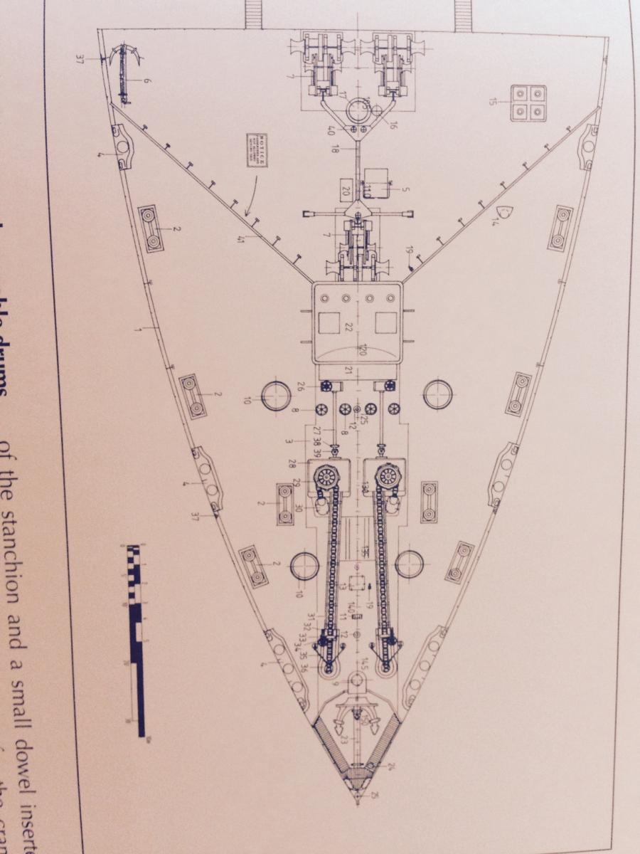
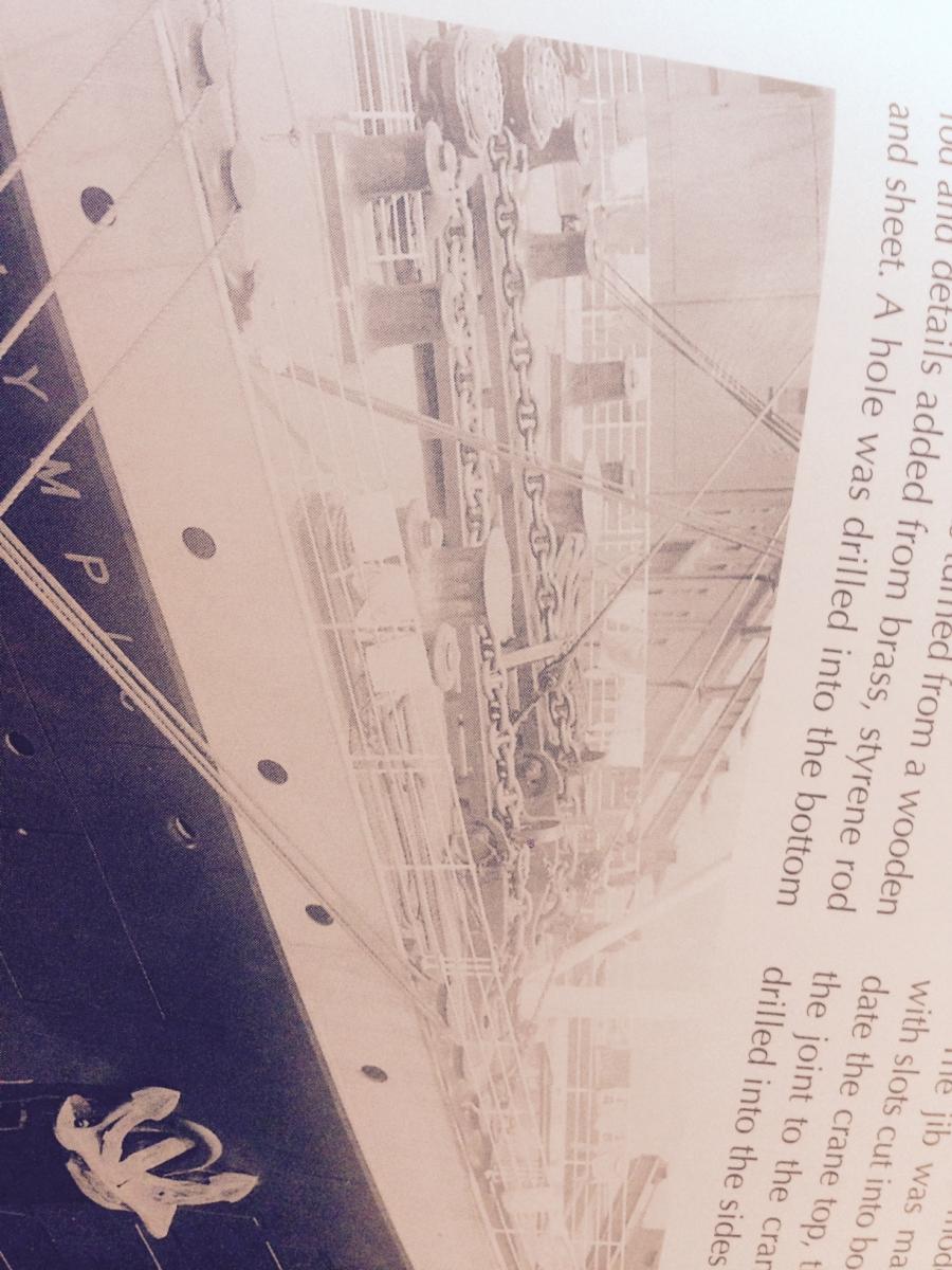
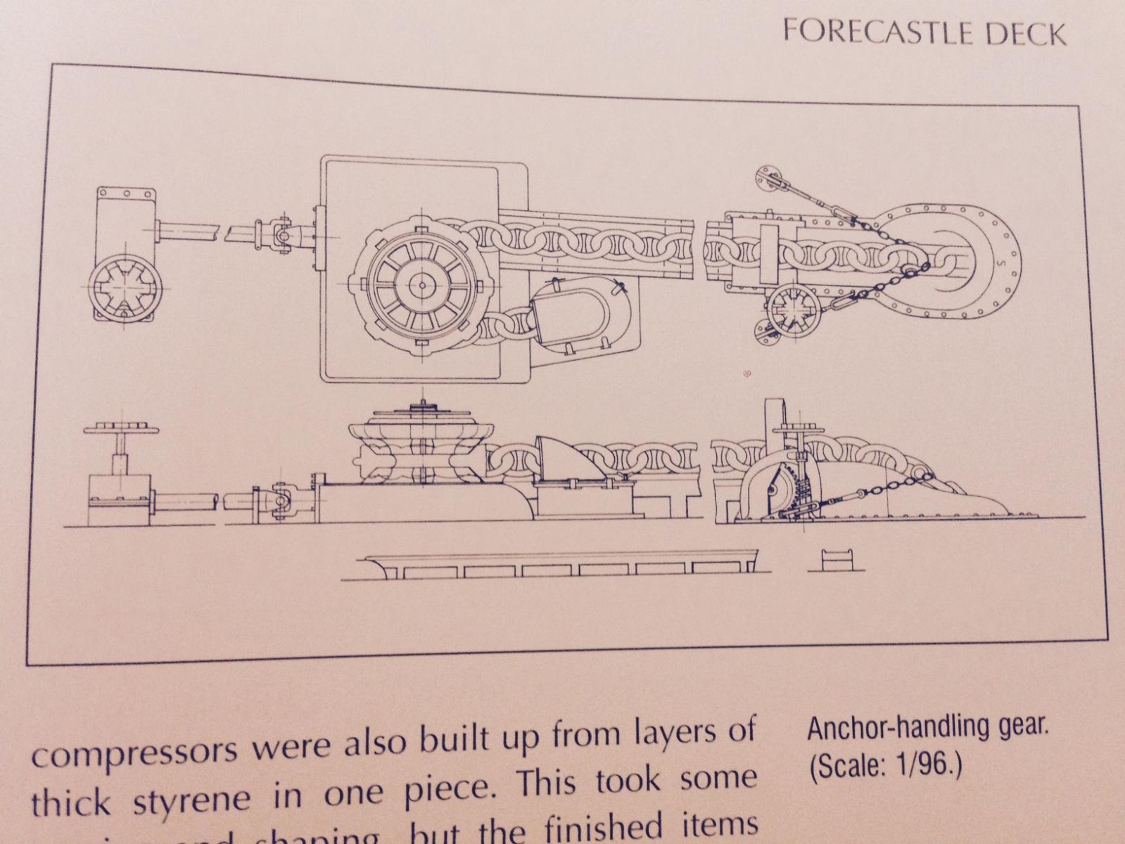
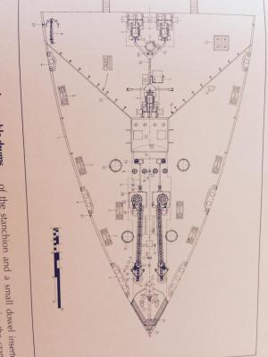
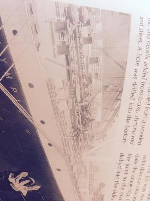
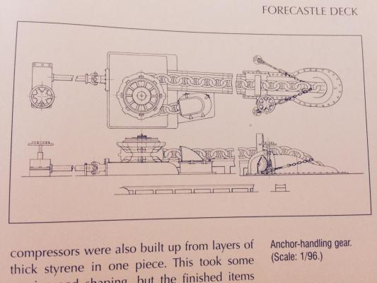
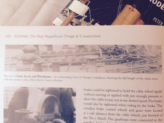
As promised, pulled out a couple books that I thought would have the info, and snapped some pictures. The chains come up through the hawse pipes, aft along the races, around the capstans, and then make an immediate 90 degree turn down into the chain locker. See the attached pictures; they are taken from "Titanic: A Model Maker's Manual" by Peter Davies-Garner, and "Titanic: The Ship Magnificent Volume 1: Design and Construction" by Bruce Beveridge et. al. Hopefully these pictures get you what you are looking for.

-
I concur. I've watched it that way several times; the sets were made with excruciating attention to detail, with several experts and many archival documents involved. A fellow named Ken Marschall, an extraordinary marine artist who is known for his incredible tenacity for research and his amazing attention to detail, felt he was actually on the Titanic itself while visiting the sets to provide feedback on their accuracy. If you want to get the best possible representation of that ship (in a non-technical format), the movie "Titanic" is the place to get it.
-
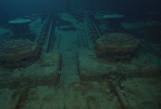
I may be able to help you with the routing of the chain on the foredeck; I have several books that I can look at that should have that information. You might also consider not looking for plans, but looking at photos of the wreck. The bow is one of the most photographed parts of the wreck, and the anchors and chains are still in place (or at least they were when most of the pictures were taken). There is an amazing overhead mosaic of the bow section taken by the towed camera sled ARGO from when Ballard discovered it in 1985 - when it was still in pristine condition, unseen or untouched for over 70 years. I did a little digging for images, and this one is (1) a neat picture, and (2) shows roughly the routing of the chains. But I will try to find something more 'official' when I get back to my bookshelf later today.
-
I like that color blue! And trust me - I believe you when you say it's taking some time to lay everything out - as you know, been there, done that! Are you going strictly off the plan, or is it just inspiration material at this point?
-
Super excited for this build; I've been a Titanic nut since I was 4 years old! A couple years ago I finished my own 1:350 scale Minicraft kit one that I had since high school, but that sat for four-five years while I went to college and got settled at my first job. However, it was the first kit I really spent time finishing well, and as such there were a lot of things I didn't do for fear of botching it and a desire to get it buttoned up and move on. For example, there are a few sheets of photo-etched brass railings, and some other items, that I didn't touch, and I didn't do any of the rigging. But I'm satisfied with what I did do. Anyway, that was my long-winded way of expressing how excited I am to see this one go together! hope there's still room in the front row
-
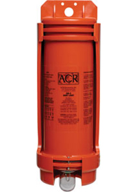
My own take on the life preservers: The life rings that we put on the boats I've been involved with as a designer, we've used rings that have a line that attaches it to a flashing beacon. Not to add to the list of 'last little details' though . Attached is a picture of the beacon I'm talking about. Since we are talking safety equipment, another little detail that would add some realism, and that would add authenticity to the boat you're building in particular, would be an EPIRB unit - they found the A.G.'s washed ashore on Sable Island (switched off). But, even without these details, the boat looks excellent. She's nearly ready to head out to the Grand Banks!

- 956 replies
-
- 9
-

-
- andrea gail
- trawler
- (and 1 more)
-
Looking great Igor! Exciting to see her come together!
- 154 replies
-
- 1
-
-
- colin archer
- lifeboat
- (and 2 more)
-
Awesome treatment, Steven! Man, I love this community of people - can't read a thing on this site and not learn something new.
-
Roger that; based on some quick wikipedia research, biremes were roughly 80 ft long. So, that would be roughly 1/2" = 1ft, giving a freeboard of about 1 1/2 ft full size. Based on a little more research, that seems roughly appropriate for the height from waterline to the opening for the first level of oars. From this website: http://www.brighthubengineering.com/marine-history/72868-types-of-ancient-war-ships-biremes-and-triremes/ "Speed and mobility were the forte for triremes and for this reason they were built low to the ground, to ensure that the oarsmen reached the water easily with their oars. The lowest row of oarsmen was just 18 inches above the water line. As a result, many researchers believed that the triremes were not meant for open seas mainly because of their reduced weight. In case they were used for open seas, the rowing port holes were protected with leather bags to prevent sea water from coming inside the ship, especially during rough seas." So, it's appropriate for the vessel type. And, I learned something new! Naval Architect standing down now Can't wait to see her launched!
-
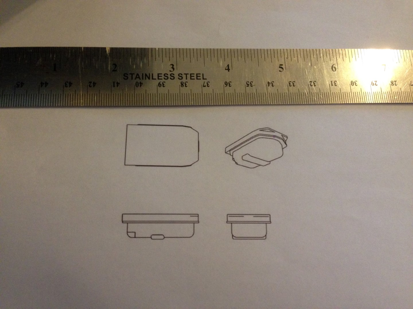
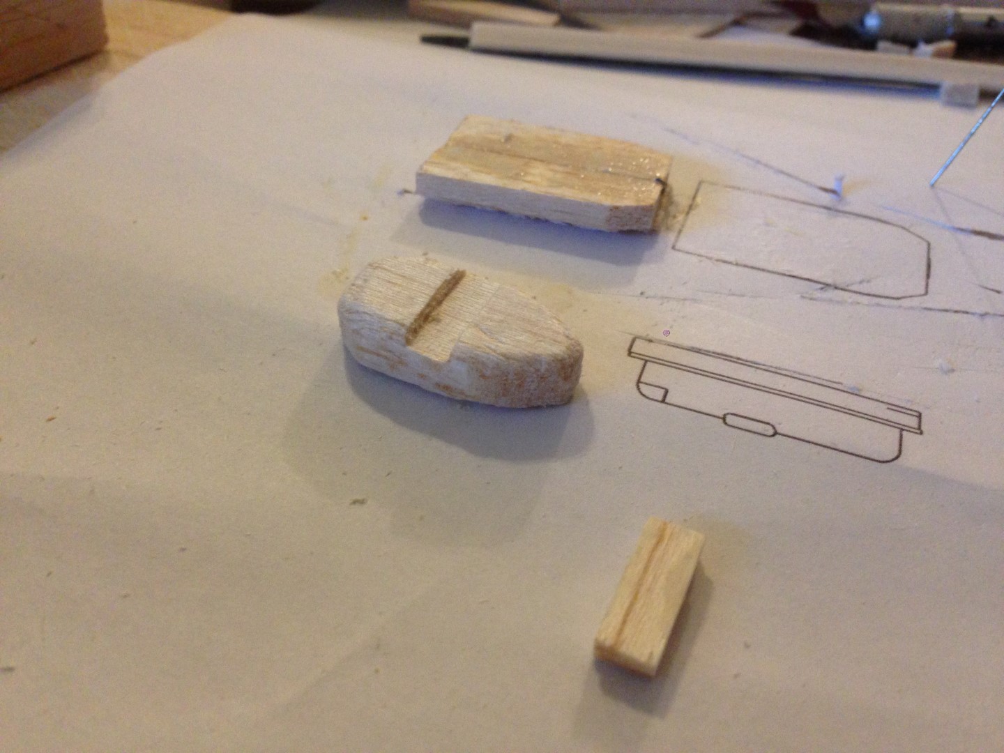
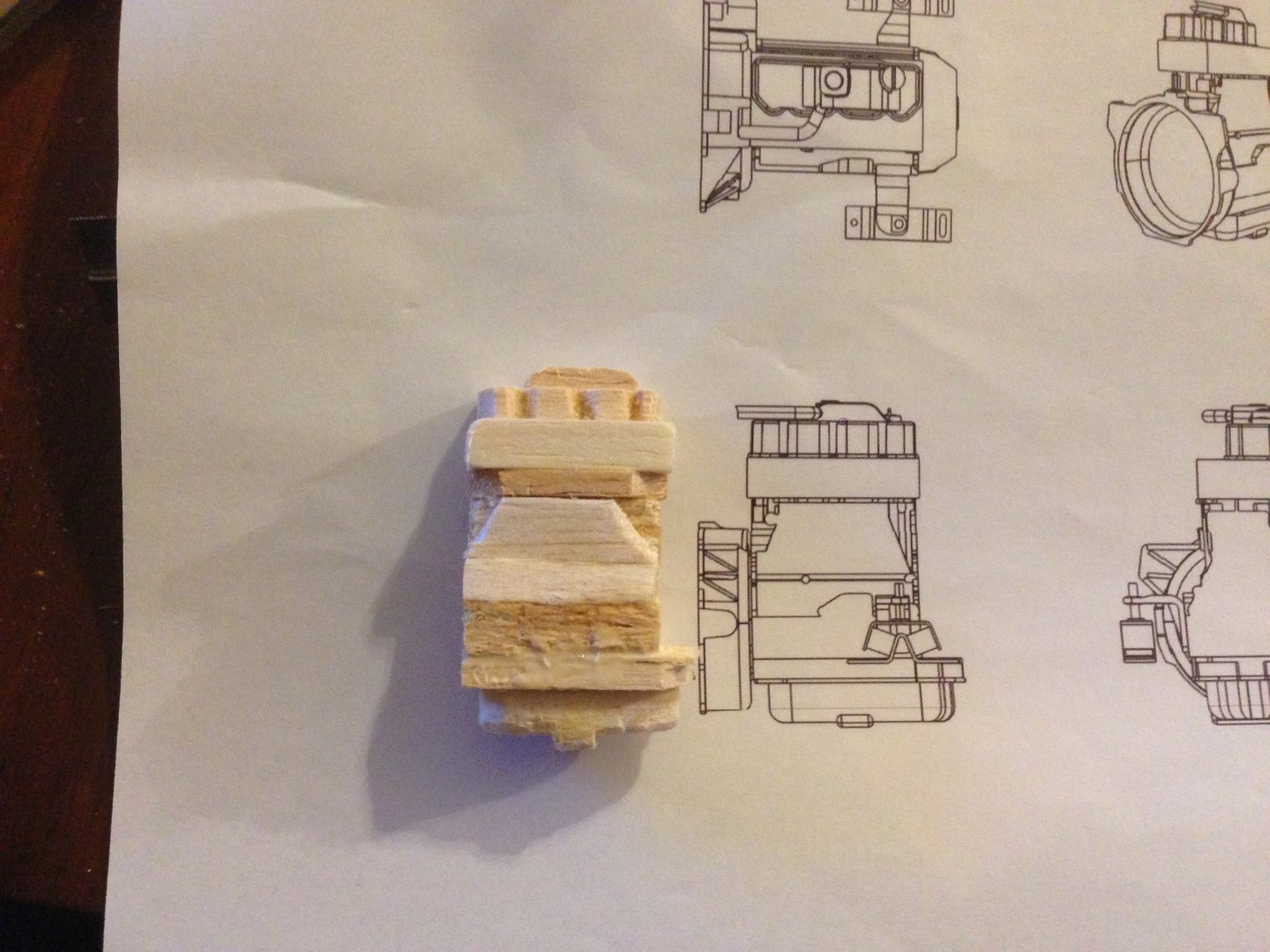
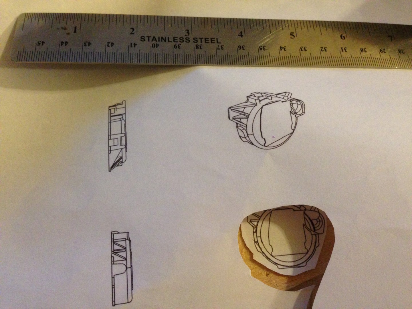
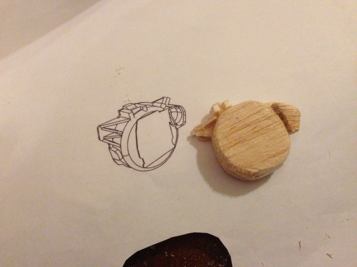
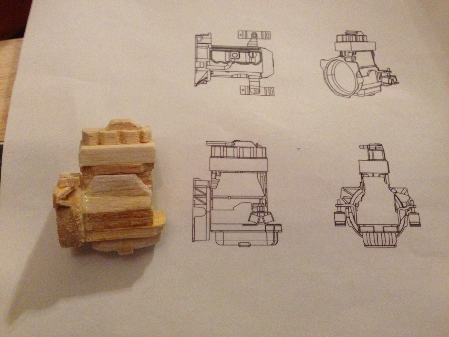
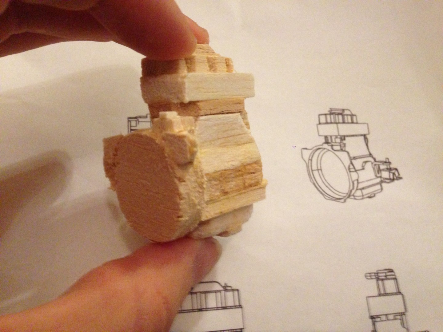
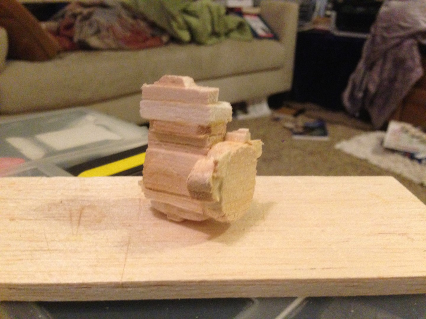
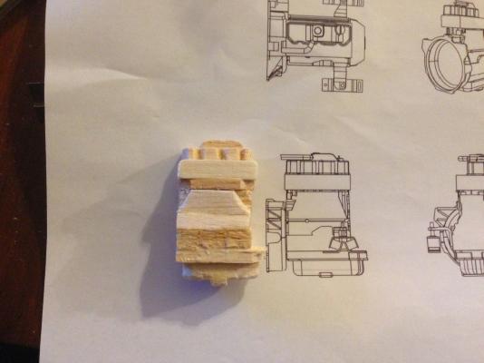
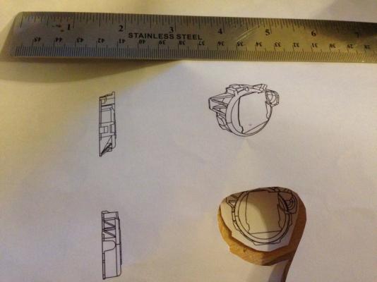
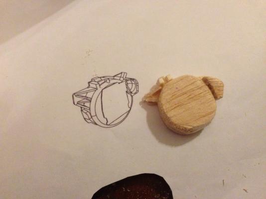
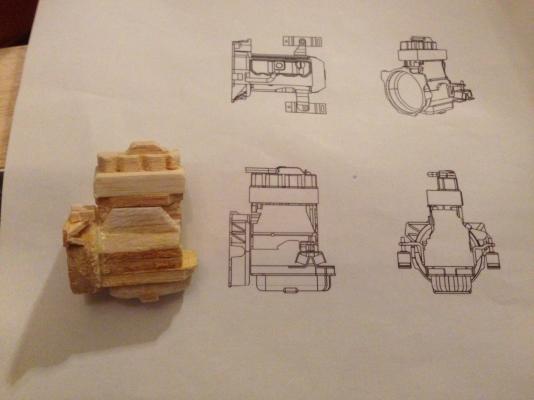
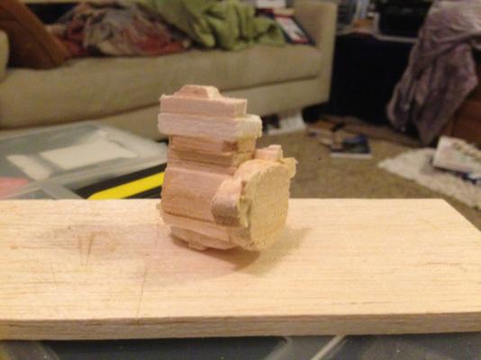
Thanks Patrick! Here it is LUBE OIL SUMP AND FLYWHEEL HOUSING I got another chance to do some work last night, so I made the lube oil sump and flywheel housing. My current overall strategy is to fabricate anything large/blockish out of the balsa wood (block, sump, flywheel, free end 'stuff', heat exchanger, exhaust manifold, etc) and get it all glued together. Then, I'll do the white glue/water wash Mark suggested, and then probably paint it. Then, I will add all the plastic and rubber pieces (hoses, injection lines, filters, etc) So, with that said... LUBE OIL SUMP I again printed the part details out at model scale, to use directly. Lube Oil Sump Part Detail I decided the best way to approach this piece would be to break it into 3 sub-parts: Parts For Sump Fabricated Then, I glued them up! Assembled Lube Oil Sump And here it is attached to the prior block/cylinder head assembly. Engine Assembly With Lube Oil Sump Added As a side note, the other part of my general strategy has been to move from simple to complex (roughly) and from inside to outside with the build of the engine. So, I started with the main block, which is logical from both a complexity and a sequencing perspective. Each subsequent piece has added another 'skill' - shaping, rounding edges, notching and fitting, etc. So, the sump was the next step after the cylinder heads because it was multiple pieces, which had a lot of edge rounding. The next step from that was a slightly more complex piece - the flywheel housing. Flywheel Housing Again, I started with a scale print out of the part. Flywheel Housing Part Detail This was a more complex part because (1) it is round, and (2) it has some small intricate detail that the previous parts had less of (with the exception of the engine mounts). I was able to capture the essence of the part, while not matching it exactly. I'm thinking primarily of the maze of angular brackets on the left side - there are four in a pattern on the actual piece, but I managed to get only two on there. But the 'feel' is the same, which is what I'm shooting for here. I failed to take any in process pictures, but here is a picture of the part assembled. Flywheel Housing Completed And, here is the engine assembly to-date. Current State of Engine Assembly I think the heat exchanger and manifolds might be next. Either them, or the free end of the engine - there is a lot of complexity there, and I need to determine if making it from balsa or scavenging from my old plastic sprues and leftover parts will be the best approach.


-
Dennis, What do you mean by 'float lines?' Are these lines on the hull? Or part of the fishing gear? Thanks, Ben
- 956 replies
-
- 3
-
-
- andrea gail
- trawler
- (and 1 more)
-
I echo Patrick's question, now that I think about it. Would be really disappointing to have a Mary Rose or Vasa on your hands. [Also, now my marine accident investigation twitch has been tickled, and I wonder how many of these Greek and Roman ships were lost because of downflooding through the oar ports....how many ships sank before they figured out the right place to put them? Uh-oh, looks like I'm not going to get anything productive done today... ] That said, I have a feeling that with models, it's generally harder to make them draw enough water, rather than have a freeboard too low. The ratio of structural and internal weight to hull volume gets wacky as scale drops.
-
Doing a build log for that one is next on my list. I just need to make sure I can finish my current project by my deadline (I'd like to have it done by my daughter's third birthday, about a year from now; at the latest by her third Christmas) P.S. - glad to see you're working out the final kinks and glitches!!
-
Patrick - that would be worse. Much, much worse. I'm not sure whether this is fortunate or not, but the Blues Brothers were just before 'my time' (timelessness of their work notwithstanding....) So, I seem to have avoided the curse of having their song running through my head. Of course, generational timing doesn't prevent me from having Gordon Lightfoot running through my head anytime I look at my yet-to-be-started model of the Edmund Fitzgerald. But, at least it's not Brittney Spears....