HOLIDAY DONATION DRIVE - SUPPORT MSW - DO YOUR PART TO KEEP THIS GREAT FORUM GOING! (Only 13 donations so far - C'mon guys!)
×


BenF89
-
Posts
316 -
Joined
-
Last visited
Content Type
Profiles
Forums
Gallery
Events
Everything posted by BenF89
-
 I’m looking forward to this! I just don’t get tired of seeing folks’ Titanic builds. Encountering the Titanic story at a young age inspired my trajectory towards my current career in Naval Architecture, so it’s very near-and-dear.
 -
Looks great! I really like her lines. Beautiful ship, even if she had seen better by the time she was a war-bride transport...
- 446 replies
-
- 3
-

-
- zebulon b vance
- deans marine
- (and 3 more)
-
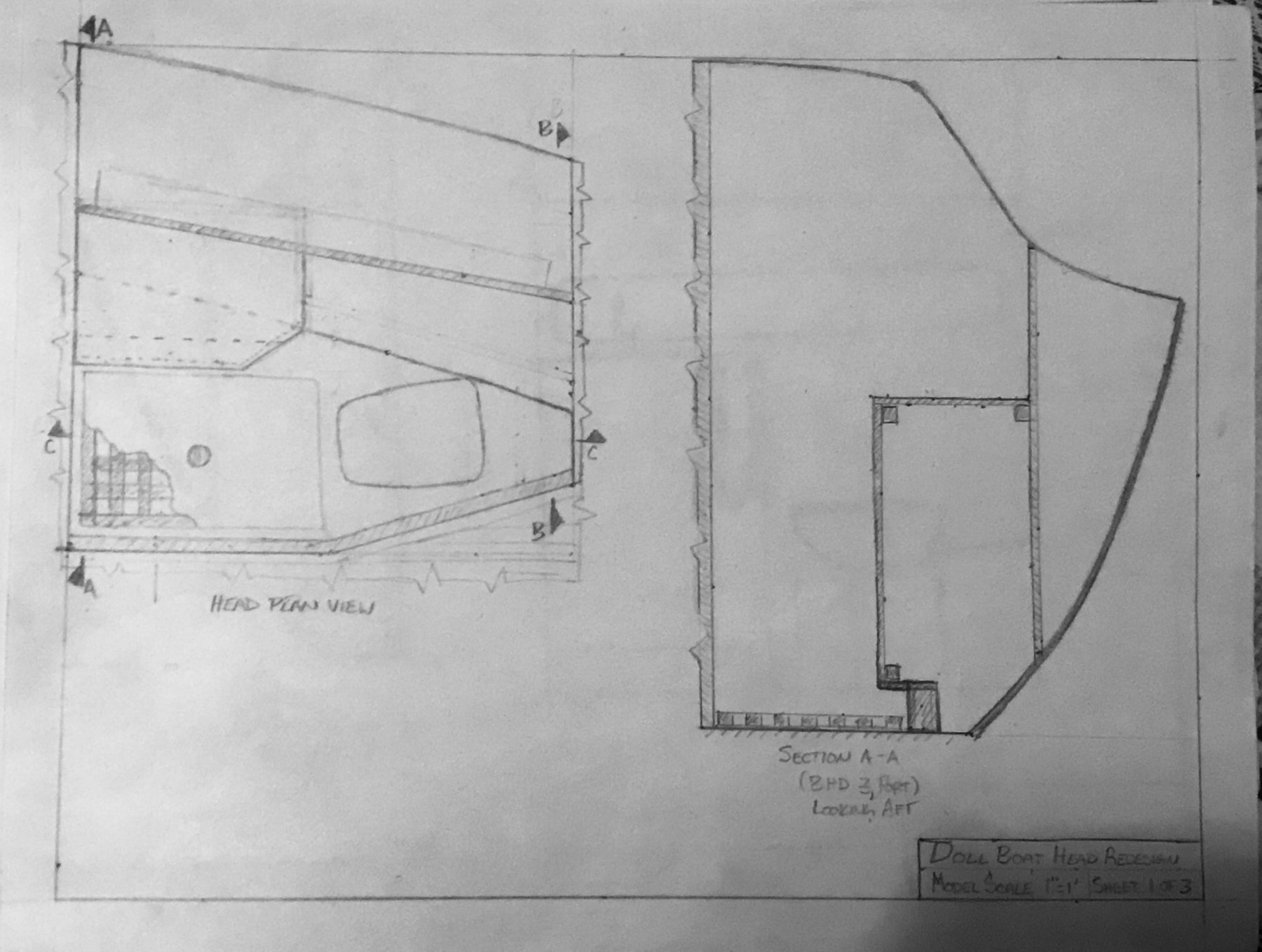
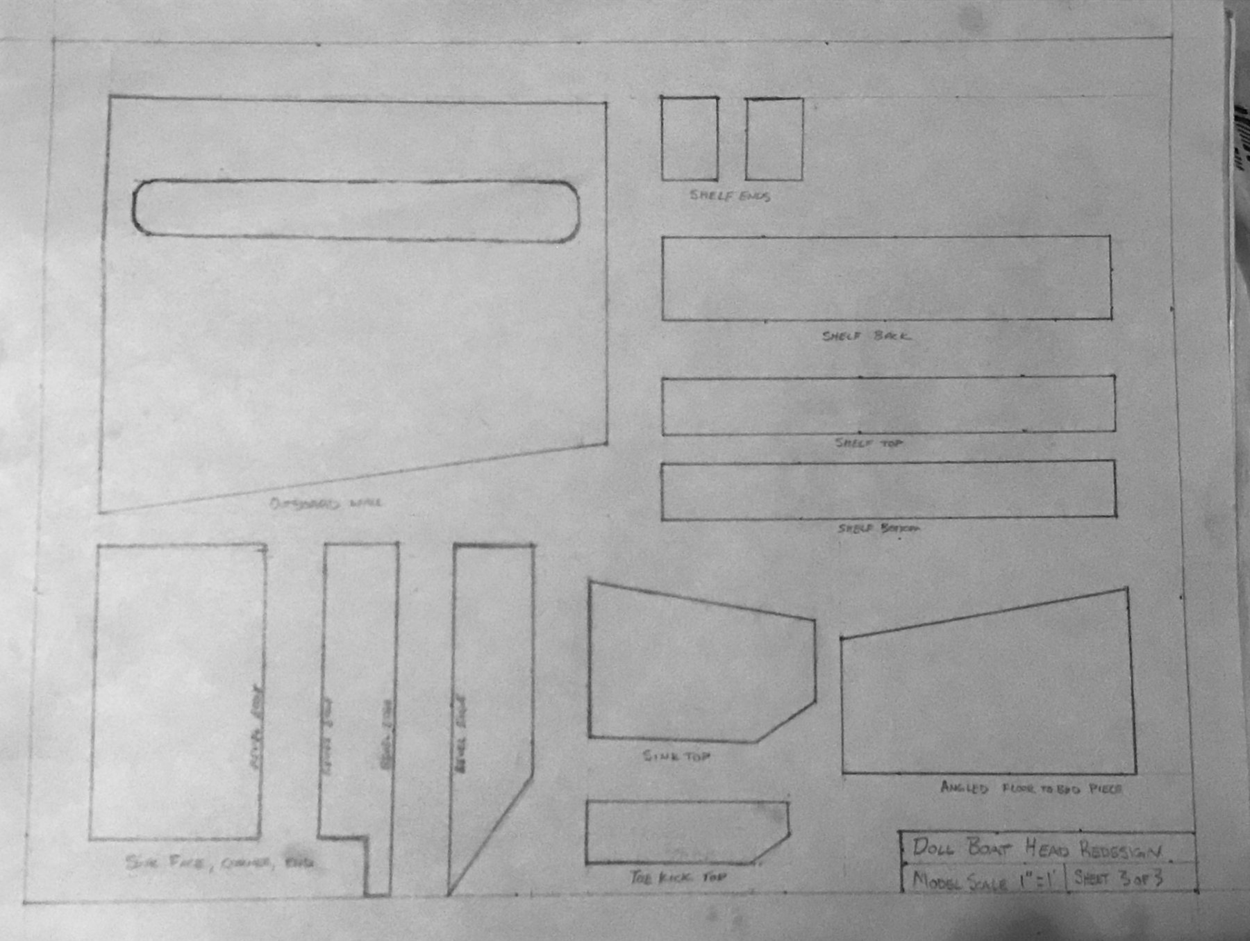
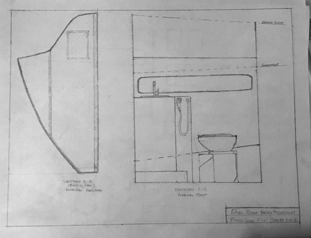
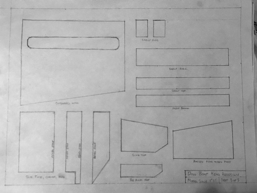
Thanks, Denis! Good to hear from you _________________ FORWARD HEAD OUTFIT - PART 5 Spent most of the ‘build time’ this week planning and drawing a new head arrangement, and then carefully measuring for part details. Results are below: Head Redesign- Sheet 1 Head Redesign- Sheet 2 Head Redesign - Sheet 3 My plan is to build as much as I can off the boat out of styrene, rather than build it in wood and have to sheath it. But the plastic-sheathed-wood route may be more robust. I suppose I’ll find out what I decide when I make it.

-
I showed the brochure to my 5 yo daughter. She said "That's very fancy. I hope it NEVER sinks." So you have a vote of approval from the two of us!
-
Have you seen Koppalakki’s build log for his Missouri? There might be some information there about what should get drilled where. Though, he’s going more for end of service life. That said, the small holes at the stem probably should not be drilled- I believe those are locators for draft marks.
-
Just discovered this log, and I’m glad I haven’t missed the whole adventure! I’ve got my sights set on (eventually) designing and building an RC workboat/commercial craft of some type, and so I’m taking lots of mental notes. Looks like a great project so far, and I’m going to enjoy following along!
- 446 replies
-
- 3
-
-
- zebulon b vance
- deans marine
- (and 3 more)
-
Thanks for the explanation- that’s way simpler than I was thinking. (I tend to over complicate just about anything...)
- 133 replies
-
- 4
-
-
- alert class
- tugboat
- (and 1 more)
-
Ha! This looks fun. I'll watch
-
Thanks, that makes good sense. I wondered if easy removal was part of it, for transportation or some other reason. Easy reinstallation is just the flip-side of that. I assume these are ‘high strength’ enough so it doesn’t get knocked off easily? How thick is the plastic between the magnets? And, how are they attached to the plastic? (Sorry for the ‘20-questions’ - I just think it’s a cool idea.)
- 133 replies
-
- 5
-
-
- alert class
- tugboat
- (and 1 more)
-
Looks great! Just curious- what is the advantage of using magnets for the monitors? Just so they are free to be manually aimed as needed?
- 133 replies
-
- 2
-
-
- alert class
- tugboat
- (and 1 more)
-
I’ll follow along, too! Sounds like an engaging research project.
-
Ah, yeah. That makes sense. I believe the naval architecture/design firm Jensen in West Seattle is under the Crowley umbrella. Also, I second the motion for a fully-RC version with rotating Z Drives, 16 light configurations, fire monitors, and deployable oil booms!
- 133 replies
-
- 4
-
-
- alert class
- tugboat
- (and 1 more)
-
Thanks! Sent you a PM. And, thanks for the yard info - that makes sense. Do you know if one of the local Naval Architecture firms did the design work, then?
- 133 replies
-
- 3
-
-
- alert class
- tugboat
- (and 1 more)
-
What a cool project! Count me in to follow along. I’m in the Seattle area, too (ish- other side of the sound). What shipyard built the tugs?
- 133 replies
-
- 5
-
-
- alert class
- tugboat
- (and 1 more)
-
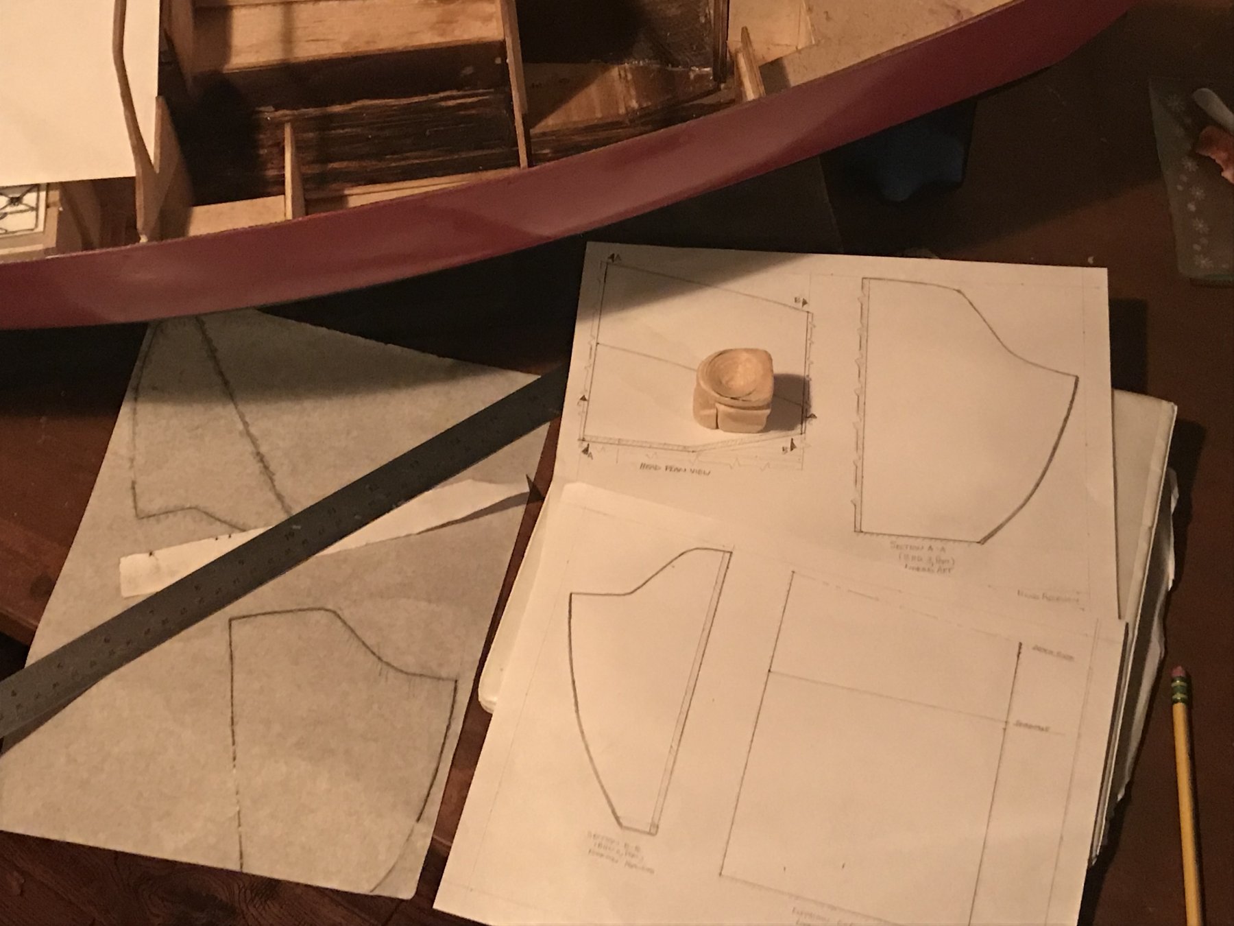
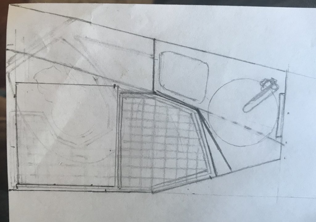
FORWARD HEAD OUTFIT- PART 4 Turns out I was quite literal when I said back to the drawing board. Tonight I got views set up to make another attempt at a workable arrangement. Forward Head Redesign Drawings- 1 ‘Ticker tape’ and tracing paper (on the left) got the basic information I needed for the plan and bulkhead sections. A stainless steel 18” ruler got me the rest. You can see the light-bulb idea I got once I saw the empty space after doing the tear out work - swap the location of the sink and MSD. I think it will make more useable deck area.

-
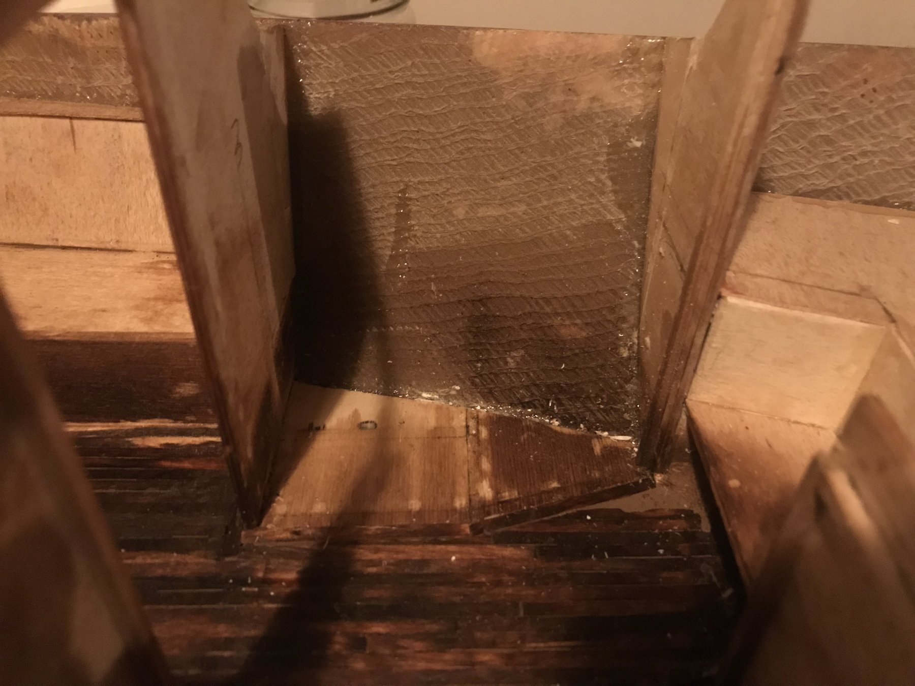
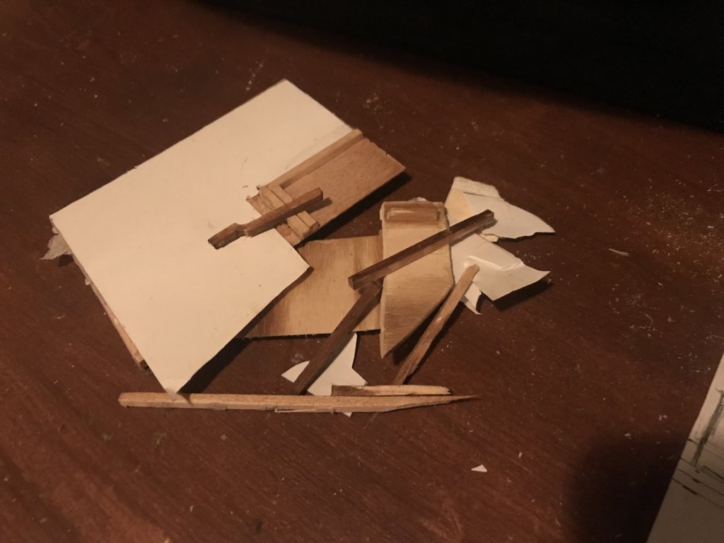
FORWARD HEAD OUTFIT- PART 3 I managed to get a little bit more accomplished tonight. Though, it doesn’t feel like accomplishment... On the bright side, seeing a ‘blank slate’ gave me another arrangement idea. More to come.

-
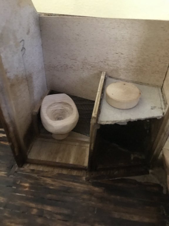
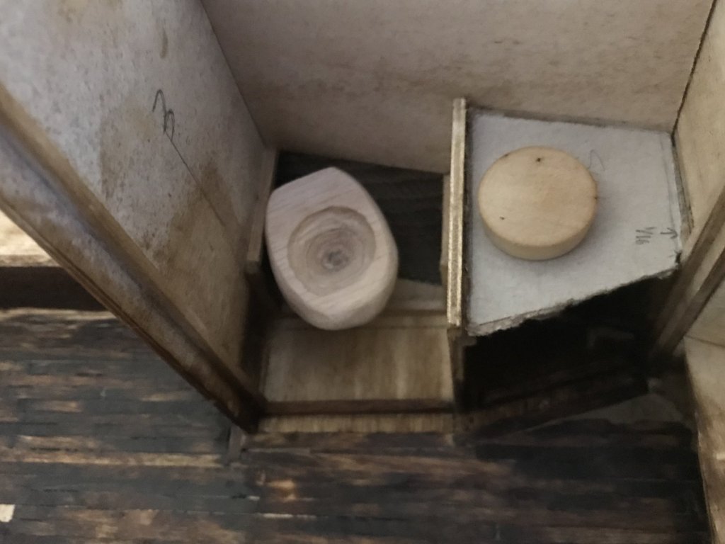
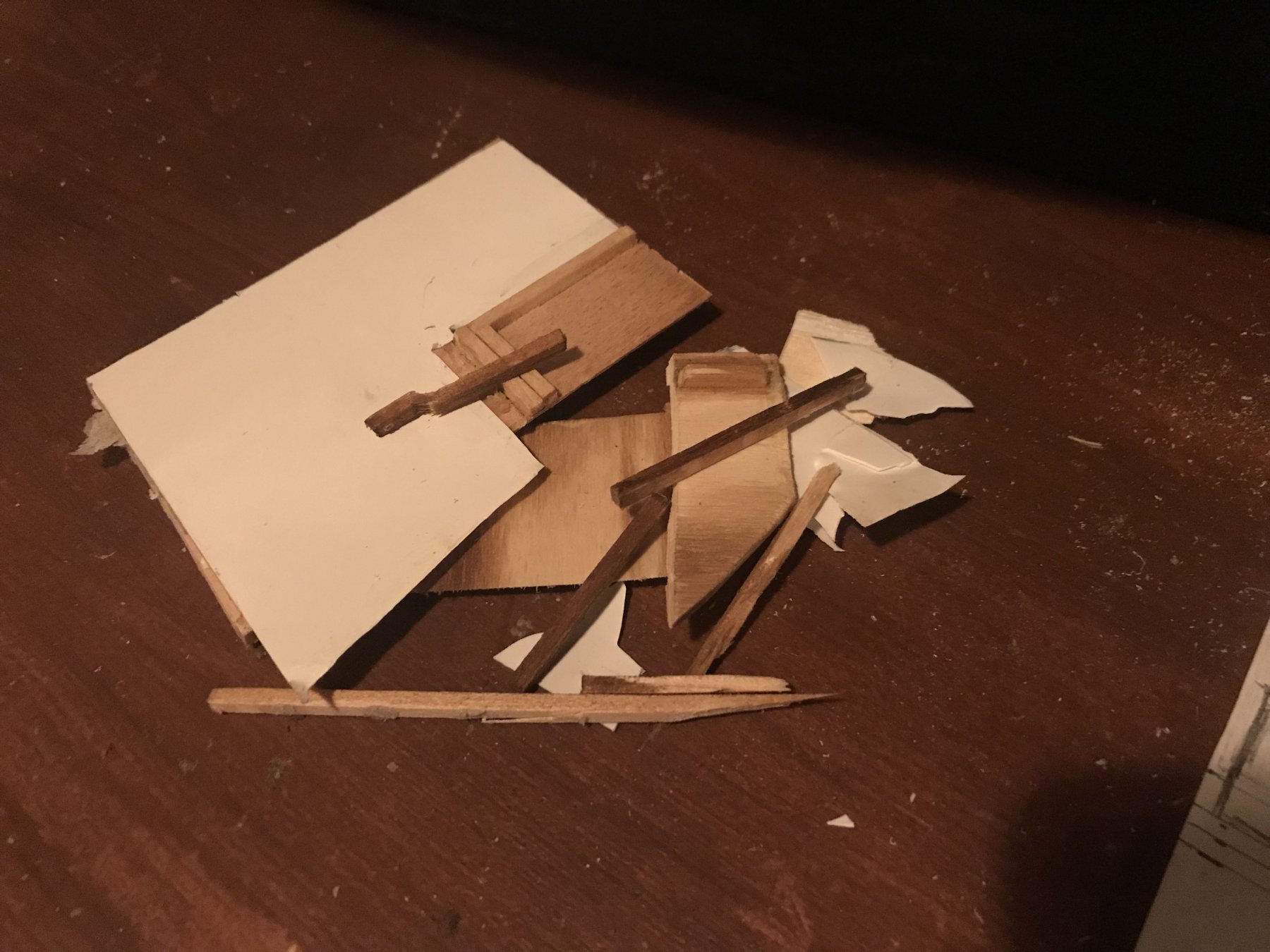
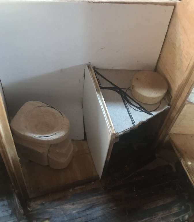
FORWARD HEAD OUTFIT- PART 2 After much deliberation, I decided that I needed to go back to the drawing board for the head. Way back when I laid it out, I must not have had a good reference for the size of the ‘marine sanitation device’ (MSD). I remember making sure there was at least room to get in, stand, and sit. Since then, two things happened that threw a wrench in the plan. First, the MSD got bigger. Second, either my space got smaller, or I didn’t properly account for ‘out of scale’ wall thickness. Both have led to rethinking the space. So, I took a ‘ticker tape’ and got the as-built space available. Then I started sketching out an alternative configuration of the space in model scale. (The picture below has a ‘working concept,’ not the final design, since I haven’t got the final design.) Forward Head Redesign Concept You can see the outline of the MSD I made last post, and it’s just too big. I’m glad I didn’t finish it, since I decided to go a different direction. I found a smaller MSD, and modeled it up. (I also printed out the dimensional details of three others in case this one didn’t work...) Second Attempt at MSD, 1 Second Attempt at MSD, 2 I placed it in the space, and it seems to work much better. With a rearrangement of the sink cabinet, I think it will work much better. MSD in Head, 1 MSD in Head, 2 So, now I’ll need to re-do the sink cabinet. Oh, also - you can see I started to do sheathing over the wood structure. The idea is to give it a ‘fiberglass insert’ look. More coming soon- going to try to get some of the demolition/rebuild work done this weekend. Plus, if the MSD works out, it needs a bit more detail work.


-
That’s an awesome piece of art. Really great work- it’s been a pleasure following the progress. Can’t wait to see Mighty Mo!
-
Hi Patrick, Thanks for the encouragement! That’s the experience I’m hoping for, at least.
-
Hi Patrick, Thanks for the compliments! They bowled me over. And no need to close the lid on the puns; in fact, you should keep pumping them out! They give me a good chuckle and help clear my head. (Ok, I’ll show MYSELF out now...) As for your question: yes, still planning to gift it over once complete. I’ve come to terms with the ‘destructive possibilities’ and have a few thoughts. Firstly, most of the really ‘breakable’ stuff is either replaceable, and/or unnecessarily detailed- which leads to the next point. I view the project itself as my enjoyment of the boat, and as my first scratch build, it’s been a lot of learning and filing away ideas for my next projects, whatever and whenever they may be. So I can let go of the boat, have lots of pictures of the ‘finished product’, and have the gains in skills and tools that the project brought about. And, finally, there’s the joy of giving it to my daughter after years in the making, and the possibility of a long time of enjoyment of it, adding ‘accessories ‘ as she gets older, etc. She’s nearly six now, and old enough to appreciate the imaginative possibilities of a doll house (or boat). So I’m having fun making it to be used- I wouldn’t spend time trying to figure out how to hinge the toilet lid if I didn’t want it lifted And if the details survive childhood, then maybe she’ll gain an appreciation for what I attempted to do. Or not, but I’ll know and apply it forward to other projects, and that’s enough.
-
ir3, I like the description as well, and maybe can add a bit on the fluid dynamics side for those interested. Right now, it’s mostly and educated hunch based on what you’ve said, what the hull and rudders look like, and what I know of planing hydrodynamics. But I’m definitely going to look into it more to either confirm or correct my thinking. Essentially, a boat ‘on plane’ is trading buoyancy (in displacement mode) for lift, and like an airplane is very sensitive to changes in trim, which itself is sensitive to variation in the center of pressure on the hull bottom. With a vee-hull, which I‘m most familiar with, there are lots of creative ways to change the center of pressure, like trim tabs. (Or aft lifting strakes like on Lou’s PT boat.) I’m not as familiar with round-bilge boats at planing speed, but I can guess at how the Lurssen effect works hydrodynamicaly. The out-from-center rudder angle will cause a slight interruption in the water flow, which would cause an increased bottom pressure right at the rudder, quite far from the boats center of gravity. The pressure ‘spike’ would create a ‘trimming moment/torque’ by moving the center of pressure slightly aft, so the boat would have to trim down by the bow a little until the center of gravity and center of pressure balance again. It’s like a vertical trim tab. Normally vee-bottom boats have there ‘cruise speed’ past the hump (the speed where the boat starts to ride its own bow wave, and therefore has the most trim) and on-plane, and so you’d use the tabs at the lower speed to keep the boat trimmed down in that range, but retracted at the high speed to reduce drag. But since the ‘hump’ is at a relatively higher speed for a long, skinny round-bilge boat, and there’s much more actual ‘squatting/sinkage’ as the boat approaches and passes ‘hull speed’, you cruise at an efficient point below the hump (since with a long, slender hull you can get a high displacement-mode hull speed). Then, you use the rudders at a much higher relative speed to keep the bow down while riding up the bow wave as you power past ‘hull speed’ and into semi-planing and planing-mode. It does make a lot of sense, but like I mentioned I’ll have to look into it more myself to see if my guess is correct, or if there’s some other effect I’m not thinking of. Thanks for the intriguing topic, ir3!
-
This is really neat! I like the camo scheme, even if it is “wrong”- it looks so right! And that’s a clever idea, placing the PE horizontal with the pieces on the sprue.
-
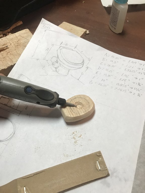
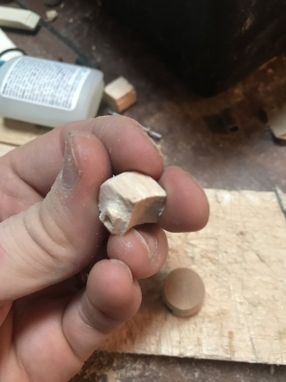
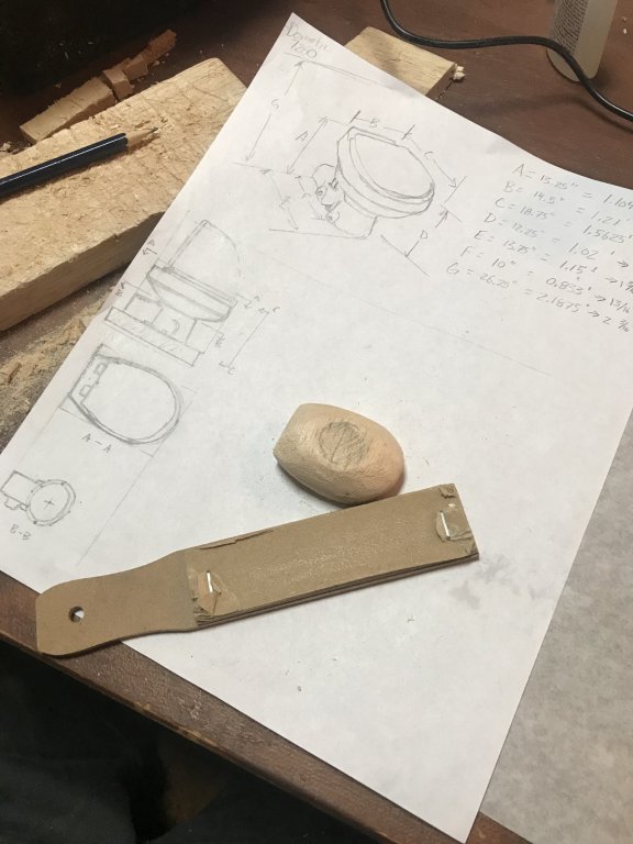
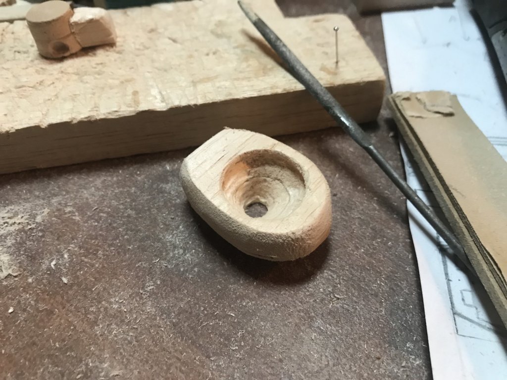
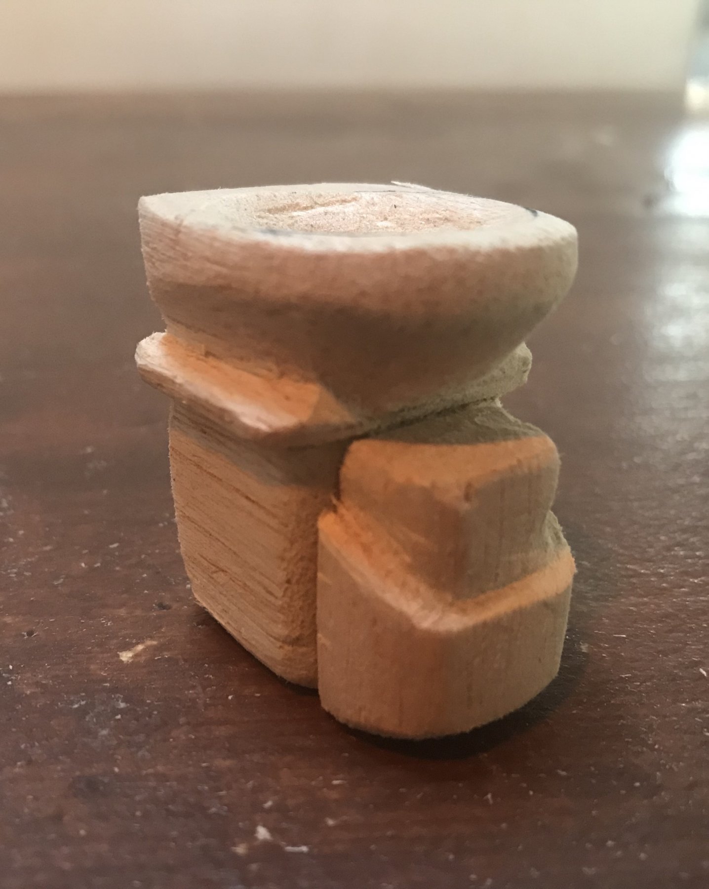
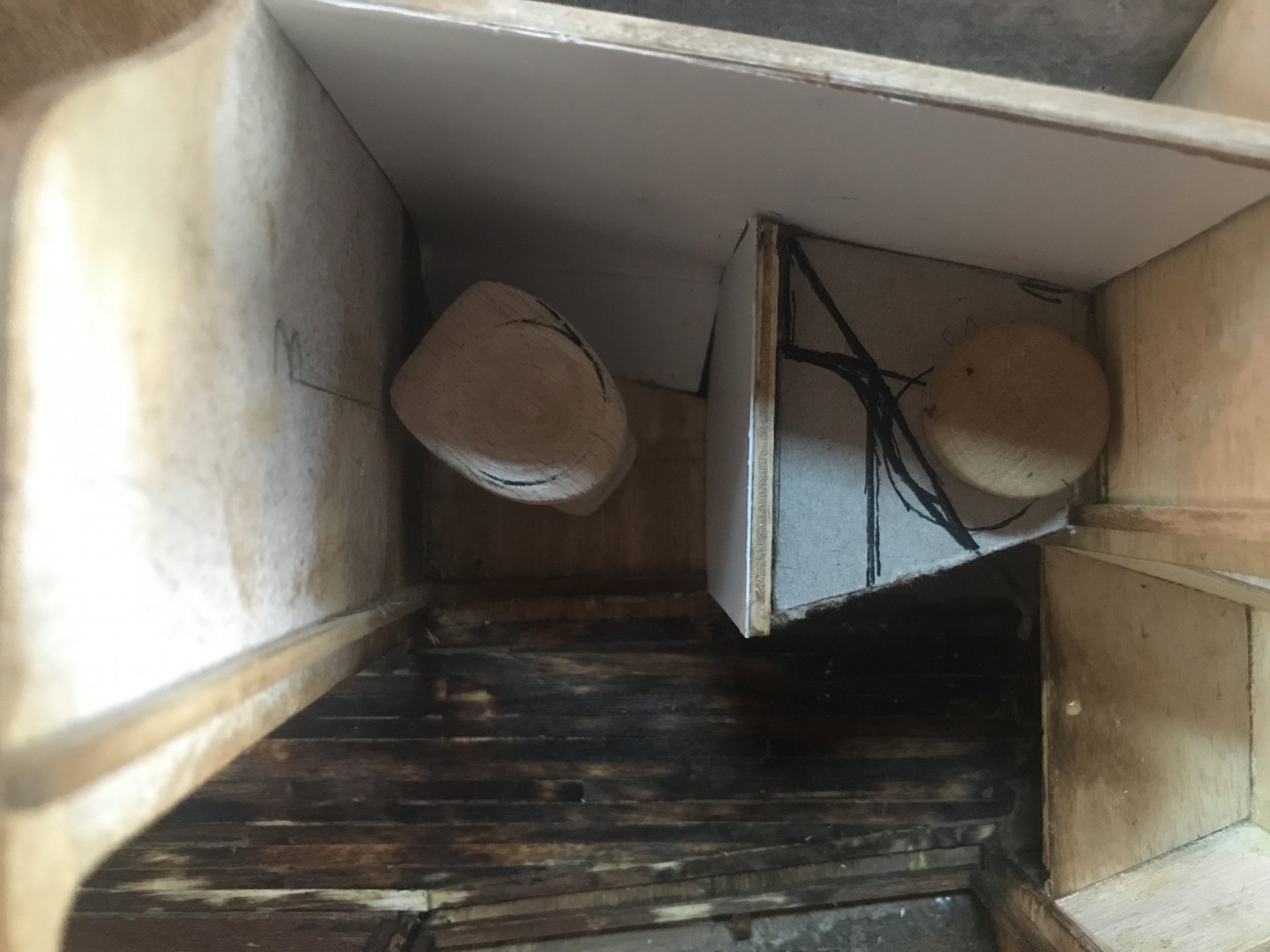
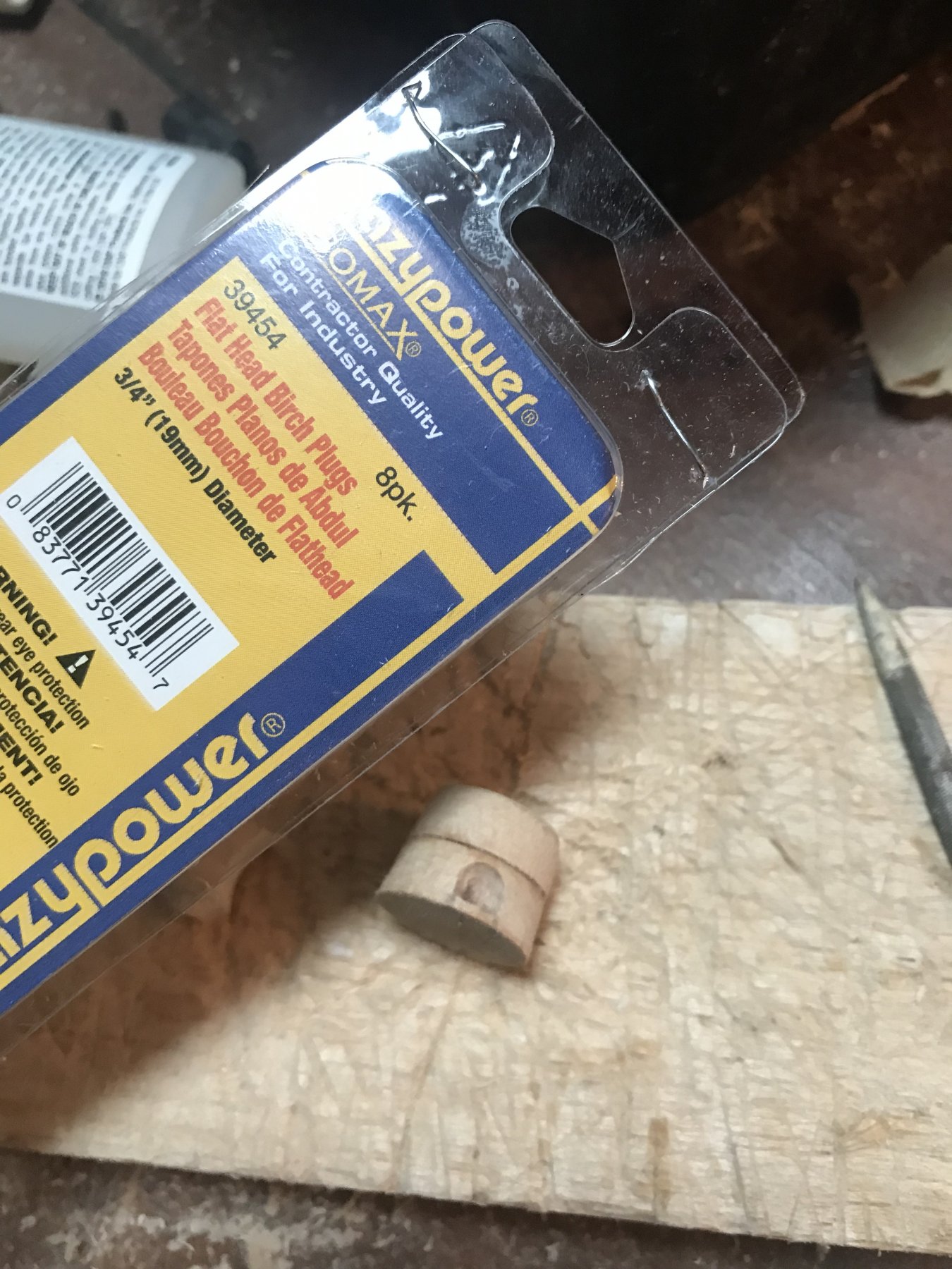
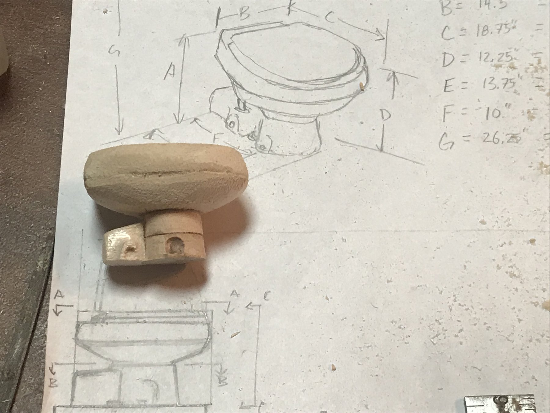
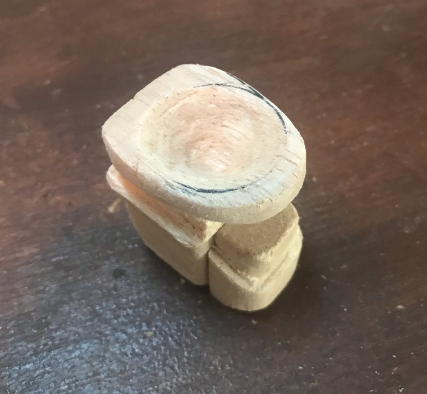
FORWARD HEAD OUTFIT - PART 1 So, I decided to start problem solving rather than ‘problem dwelling’ on the issue of fixtures and furnishings that were racking my mind, starting with the head compartment, and specifically the toilet. Can’t hand-wave it away with some vaguely suggestive artistic license in 1:12 scale! I began by actually selecting a model to model- I had a catalogue I picked up at a boat show a while back when I was collecting any research materials I thought might be helpful in outfitting the boat model. Fortunately, I kept it during all the cleanout that happened during our remodel this summer. It was a Dometic brand catalogue, so that’s the only reason for picking that brand. I selected a MasterFlush 7260, because I liked the look and thought it would be reasonably sized for the tiny head compartment. More on that later... With the model of ‘equipment’ identified, I made some rough drawings based on the limited dimensions and pictures in the catalogue. I decided to use balsa wood chunks, and do two layers for the bowl, a small chunk of square bar for the pump housing, and got myself some 3/4” diameter woodworking plugs that I used for the pedestal. Once installed, I’ll use the O-Rings I got for the engine hoses way back to simulate the water supply and ... erm... ‘discharge’ hoses. So here’s some so-far pictures. First up - shaping the bowl. This was made from two layers of balsa cut to the top-view outline and super-glued together (my rough sketch is in the background): Initial Shaping of Bowl With the bowl shaped, I started hollowing out the inside. I used my new Dremel- it was fantastic! I don’t think I could have done it without it. Certainly not as well. Starting to Hollow the Bowl And a picture with the inside completed: Bowl Inside Carved Out Next I tackled the pedestal. As mentioned, this was two 3/4” birch woodworking plugs superglued together and sanded to shape. I used the Dremel to hollow out the recesses above the bolting mounts in the side of the pedestal. Pedestal Construction Then I made the pump housing that goes behind the pedestal. The inlet hose goes into the raised inlet connection on the left side. The discharge comes out the right side. Pump Housing Finally I super glued all the pieces together: Assembled Toilet, Minus Seat and Lid Of course, I wanted to see how it fit in the head. Let’s just say that (a) this is not a luxury master bath, and (b) my idea of a ‘boxing-in’ the head inside some joinery isn’t going to happen; at the very least I need to seriously rethink the idea. The good news is that it pretty much physically fits in the space... Test Placement View 1 Test Placement View 2 I think there’s barely room to stand at the sink. Let’s hope that wherever this live aboard is home ported has decent restroom facilities. Anyway, next steps are to (a) make seat and lid, (b) figure out how to hinge them, (c) paint it a nice sanitation white, and (d) install in the head compartment. For this last step I even downloaded the installation manual to make sure the hoses look right! Till next time...