


jbshan
-
Posts
1,222 -
Joined
-
Last visited
Content Type
Profiles
Forums
Gallery
Events
Everything posted by jbshan
-

Advice for planking
jbshan replied to Slowhand's topic in Building, Framing, Planking and plating a ships hull and deck
Thistle, correct in regards the change of attitude of the second plank, but also for the garboard. The trick is to not let the fore end of the garboard get too high up the stem, as here there is less distance to cover with the given number of plank. At the stern, sometimes the garboard gets very wide, or a stealer is let in. Lining off prior to planking will help determine which may or may not be the case. -
Advice for planking
jbshan replied to Slowhand's topic in Building, Framing, Planking and plating a ships hull and deck
Mike, one way to sequence the plank is to start at both keel and sheer, so the final gap or hole to be filled is on the widest part of the hull and easier to get at. -
The plans Darrell is working from show the first shroud and a runner pendant as the first 2 put over, one port, one starboard, on the lower masts. Lever shows a pendant and shroud combined also, as the first two, fig. 168, on the lower mast, and pendants on the topmast, fig. 190
-
location of stud sails (stuns'l) when stowed
jbshan replied to timboat's topic in Masting, rigging and sails
Yes, Jud. The stuns'ls were bent to their own little yard with which they were hoisted as a bundle into position to be spread by assorted tackle. No doubt they were stowed below somewhere when not needed. Lever and Harland have some good illustrations showing the process. -
location of stud sails (stuns'l) when stowed
jbshan replied to timboat's topic in Masting, rigging and sails
Looking through my library, the sails had their own little yard to which they were set, and which assembly was hoisted to the booms/yards that were kept retracted on the yards. The booms were got out into position, then the sails/jack yards were hoisted into position and set above and below. The lower yards pivoted out from the channels and were guyed into position. There is a lot of loose gear floating around until everything is in position and belayed, but these weren't set except in fairly benign conditions. There were of course probably many variations. -
If you turn all those lights on at once, A, go outside and watch the meter go round and round and B, make sure you put on sunscreen.
-
The materials used in the model would keep outgassing for years and your inert gas would have to deal with that. Better, perhaps, to have some screened holes beneath the model mount base to allow room air to circulate naturally.
-
Making Rope
jbshan replied to ca.shipwright's topic in Rope Making/Ropewalks's Discussions about Rope Making
VERY roughly, three strands of x diameter will yield one line of 2x. -
Part of the restraining action after firing is the training tackle having to run through the blocks. A video of reenactors where the gun doesn't recoil merely indicates there was no ball involved. Equal and opposite, remember? For tight quarters they had flexible rammers where the handle was stiff rope. For live fire, try this: or google vasa cannon.
-
Wow, Darrell. It was worth the 5 days. As you weave your spider's web or bird's nest of lines, you may find as a friend of mine told me once, the routing of a line may change to avoid chafing on a line that is already there. Not doing all the running rigging may make this less important, but some of the lines need to pass through the shrouds, for instance, to get to their belay point and he said the old boys would choose a path for it so it wouldn't chafe.
- 648 replies
-
- 4
-

-
- niagara
- model shipways
- (and 1 more)
-
Port lids should be about twice the thickness of the outer planking, Mike. Outer layer would match the hull planking, tumblehome, any wale or thicker plank present where the opening crosses, to make the outer surface smooth when the port is closed. The inner layer would be set back or held back a bit to make a rebate to fit inside the port lining. Reference the destructions for your Niagara model. Oops, your Niagara won't help. Goodwin, Construction and Fitting will help, if you have it. Also try this: http://modelshipworld.com/index.php/topic/7390-gun-port-lids/ The pics show how thin the lids are, also one or two show the lip formed by the port lining.
-
Darrell, some folks that don't put sails on make a coil of line to hang at the point where the sail would normally go.
- 648 replies
-
- 2
-
-
- niagara
- model shipways
- (and 1 more)
-
I am currently working on the Model Shipways model of Philadelphia, of 1776. You can check some of the other much more comprehensive build logs on this site to see the construction sequence. I am at the point where I will soon be mounting the deck panels. The after corners of the fore deck have an ogee-shape cut into them, as does the replica at the Lake Champlain Maritime Museum, as does the original at the Smithsonian. Why, my devious mind asked, what is the purpose of this, it doesn't make sense to have this shape simply sticking out unsupported, but was finding no satisfactory answer. One of my correspondents gave me a link to a Doctoral thesis posted on the Texas A&M website, by John Bratten. The link is: http://nautarch.tamu.edu/Theses/abstracts/bratten.html In his paper, he prints small versions of plans developed by the Smithsonian from the original vessel. These include a view of the structure supporting the decks. Except for the foremost frame, there are lodging knees at the ends of the fore deck beams, and the ogee shape covers the knees pertaining to the after beam. Problem solved. There will be one pair of lodging knees on my Philadelphia. Additionally, although I won't be putting them in, there are pillars on the centerline of each fore deck beam, down to the keelson, the middle deck rests on large baulks of timber under the beams, while the after deck seems to have need of no extra reinforcement beyond the beams. It was apparently at least intended to have this at a higher level to allow guns to fire over the top of the bulwarks, but this was cancelled and the deck installed at a lower level. The dissertation is almost 350 pages, so there is a lot there for the interested student.
-
A note: Because of circumstances outside our control, none of the wiki links I have may have used in my writings are operable. From here forward, I will post pictures along with the messages.
-
Nice and neat, Darrell. If you're not a plastic surgeon you must be a weaver.
- 648 replies
-
- 3
-
-
- niagara
- model shipways
- (and 1 more)
-
A lot of what we do is to simulate things we know should be a particular way, but it's just too darn small.
- 843 replies
-
- 2
-
-
- niagara
- model shipways
- (and 2 more)
-
Mike, there are any number of ways to space the deadeyes. You have found one that I haven't seen before.
- 843 replies
-
- 3
-
-
- niagara
- model shipways
- (and 2 more)
-
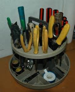
Early days, Mike. You'll work it out, then you can make your labels more permanent. I don't have depth enough for drawers so have a couple of these.
- 843 replies
-
- 2
-
-
- niagara
- model shipways
- (and 2 more)
-
A further thought: Assuming the units are modular, you could have some drawers for 'rigging' or 'wood work', then move those drawers closer in reach when you're doing those types of jobs.
- 843 replies
-
- 2
-
-
- niagara
- model shipways
- (and 2 more)
-
Mike, I had a chest of drawers at work that I decided needed labels. I got some 'decorator' tape, electrical tape in colors, and wrote labels on the tape. Red was for fractional, yellow was for metric, white for universal, then 'sockets, 1/4", 3/8", 1/2"', pliers, or "wrenches" on red, "wrenches" on yellow, you get the picture. If something didn't work out, the tape could be changed. In your case, if the drawer fronts are paper, you could write on the paper, then cover up with the tape and write the new designation. I highly recommend labeling, there are too many drawers there not to have some sort of storage system.
- 843 replies
-
- 2
-
-
- niagara
- model shipways
- (and 2 more)
-
In this case, rabbit is spelled rabbet, in which the rabbeted edge is formed by a rebate. Just so we're all clear on this. :-)
-
I use Elmer's white glue, but whatever you use, the glue needs to soak in to both surfaces for a good bond. Any sealer between layers of plank might interfere with that.
-
Darrell, I put my page in my signature, but in case it doesn't link properly, try this: http://modelshipworld.com/index.php/topic/9953-lexington-by-jbshan-dlumberyard-164-from-the-seaways-practicum-by-clay-feldman/
- 648 replies
-
- 2
-
-
- niagara
- model shipways
- (and 1 more)
-
Model shipways kit. Cut the taper into four pieces and glue them up, then round off the corners. It's a technique I've seen in books for small sailboats. There are good plans of Philly from the Smithsonian so scratch is not outside the known universe for a skilled workman. I did the square stick thing for my Lexington model, in my 'build log'. I think you can find it through my avatar. Guess it's time to put it in my signature.
- 648 replies
-
- 2
-
-
- niagara
- model shipways
- (and 1 more)