

Jeff-E
-
Posts
699 -
Joined
-
Last visited
Content Type
Profiles
Forums
Gallery
Events
Posts posted by Jeff-E
-
-
-
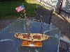
I have also made a start on the main deck hatches. These are made from 2mm pre-cut ply board.
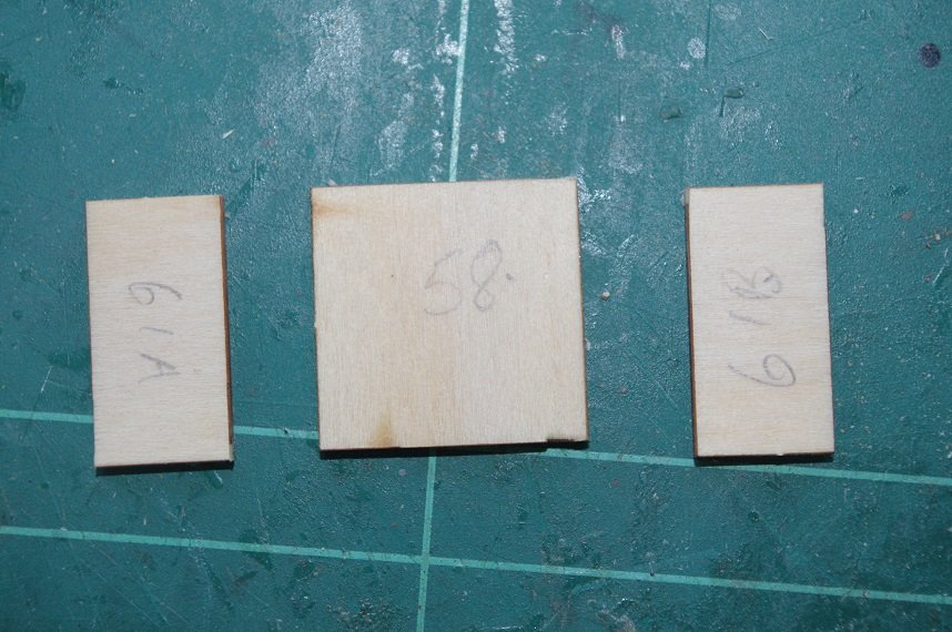
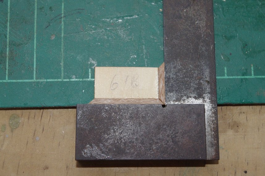
They are then lined with 2 x 3mm walnut around the edges.
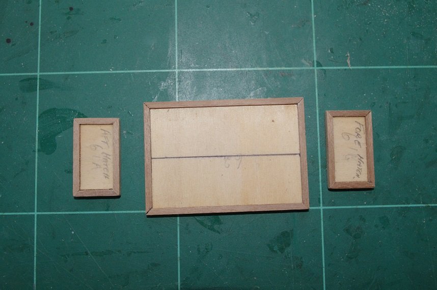
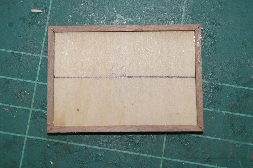
They will have 1x4mm walnut boards fitted to them later along with ring bolts and rings to lift them off with. I did consider using gratings but thought that the hatches would be sealed from the elements and could be opened to air below decks. The underside of the hatches was sanded to conform to the camber of the deck.
Thanks for looking and the likes.
All comments welcome.
- JpR62, GrandpaPhil, ccoyle and 1 other
-
 4
4
-
Yes it is a bit unusual and complicated and I don't know how accurate it is but I am going off the plans in the maritime museum and the model in the powerhouse museum and a few other plans and drawings I managed to find. I do think it is an improvement on the kit design however.
On 6/9/2020 at 5:18 PM, clearway said:are you going to just have a flat stern where it meets the counter or are you going to try the oft dreaded tuck?
Yes I will be bending the planks at the stern to meet the counter I hope they turn out as this will be my first attempt at doing this.
I think I said at the start of this build that the strip timber was of a reasonable quality, well unfortunately it is not. While it is milled smooth on all faces the thickness and the width of the strips is very inaccurate. The supplied planks for the first planking is supposed to be 2 x 5mm limewood and 50 planks, 500mm long are supplied which is just enough to plank the hull with maybe 1 or 2 planks left over which does not leave a lot of room for error. That is fair enough but of the 50 supplied planks I have 13 that are consistently 2mm thick and 5mm wide over their length, the others vary between being 5mm at one end down to 4.5mm at the other and 2mm thick at one end down to 1.3mm at the other and anything in between.
I have sorted through them and come up with about 20 that are useable and have ordered a pack of 25 2 x 5 x 915mm birch planks from a hobby supplier in Newcastle which should be enough to do the job.
I also checked and measured the Teak strips for the second planking these were also found to be of inferior quality there are 30 supplied which is again just enough to do the job, they are supposed to be 0.6 x 5 x 500mm but some of them are paper thin, you can hold them up to the light and see through them and a few are split and cracked. So these will not be used at all I have a stash of 0.5 x 6mm Sapele from the other kit I mentioned earlier that will replace it.
So on with the planking, as I said the first planking is 2 x 5mm, which will be a bit of a challenge to bend around some of the tight curves of this hull. My prefered method of bending planks is to soak them in cold water for half an hour or so and then pin them to the hull and let them dry, once dry they are removed and any slight adjustments are made and then they are glued to the hull. I find by using this method the planks conform to the shape of the hull and very little force is need to get them to lay the way you want them to.
I think that the first plank and the garboard plank are the two most important planks to get right, if these are positioned correctly the rest will fall into place.
So the first plank on this ship is to follow the line of the main deck along the middle section and the bottom edge of it to end level with bottom edge of the stern counter while the front allowed to follow it's natural line at the bow.
The bulwarks will be planked next and then the garboard plank will be fitted and the planks in between it and the first plank fitted.
- Fernando E, GrandpaPhil, JpR62 and 2 others
-
5
-
Good work Scott, I like the modifications you have made to the windlass.👍
-
-
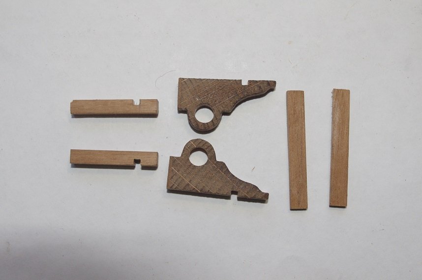
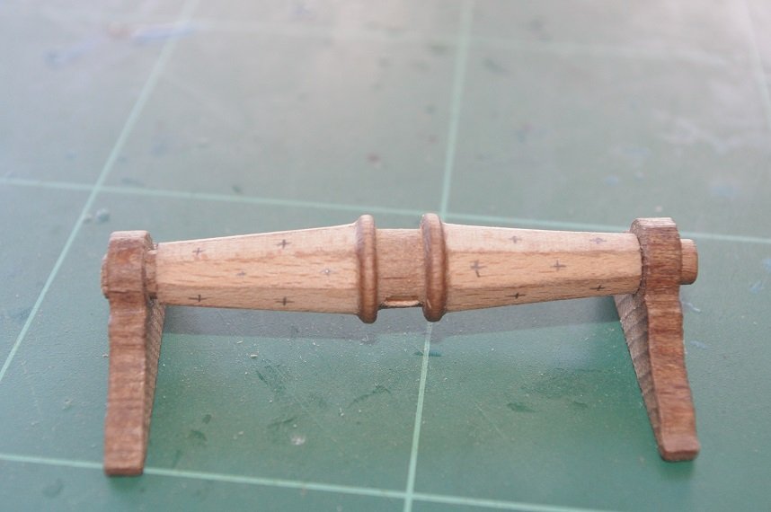
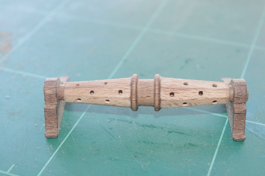
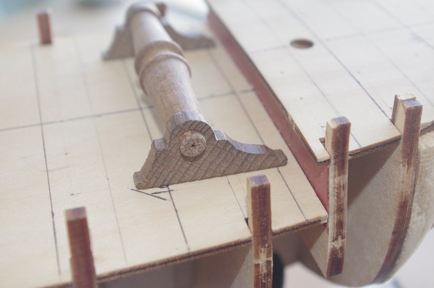
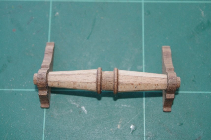
The windlass supports were modified so that they will stand upright the back scroll was cut off.
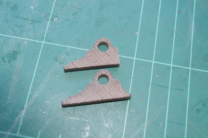
The offcuts were saved as they will be used as knees in front of the supports on the fore deck. A 2 x 2mm slot was cut into each support 8mm up from the foredeck for the fore fife rails. The supports for the pawl and the belfry were made from 4 x 4 mm walnut and also had slots cut into them for the fife rails.
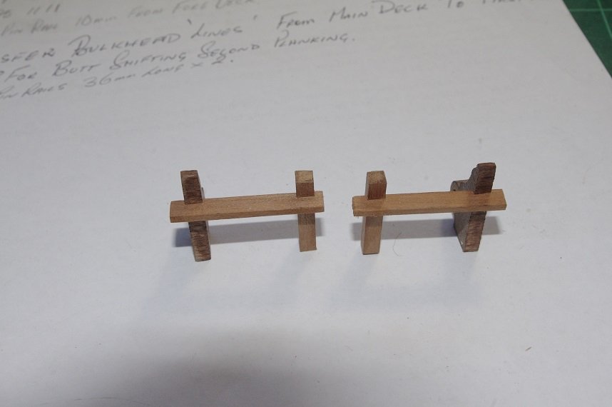
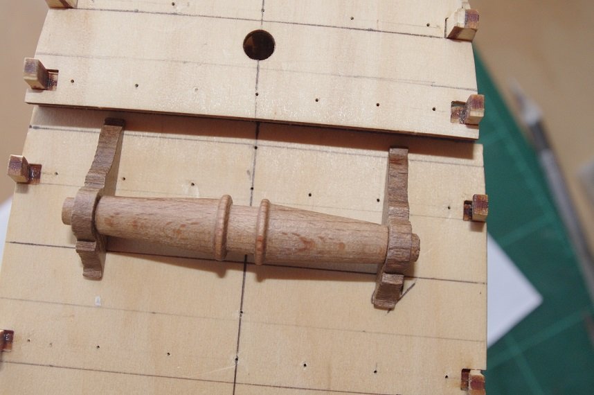
The parts were then dry fitted together.
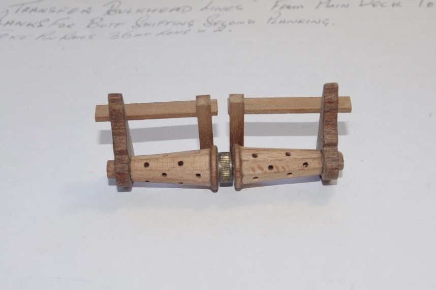
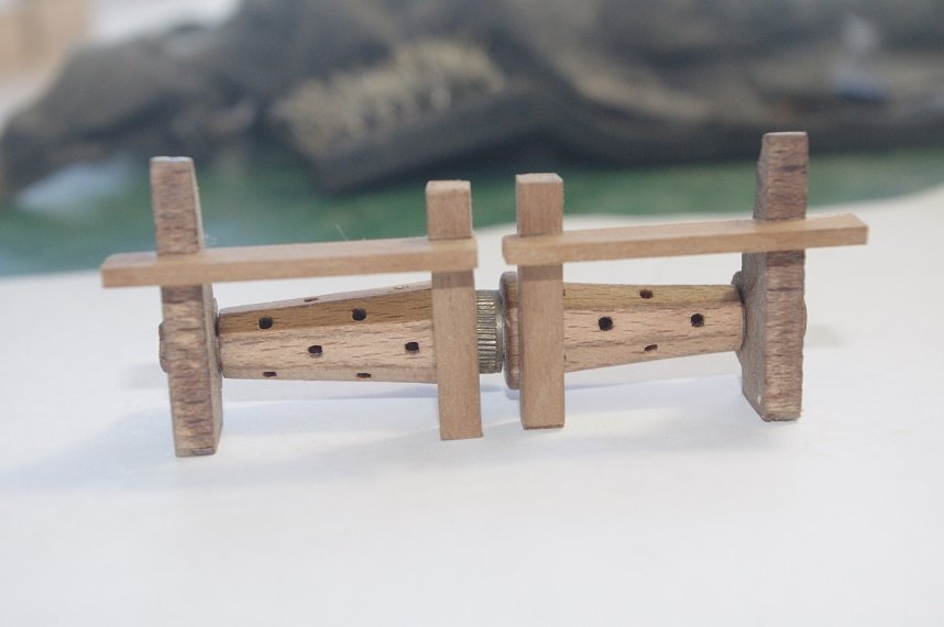
And with the windlass drum fitted.
Thanks for looking and the likes.
All comments welcome.
- Tompslattery, GrandpaPhil, clearway and 2 others
-
5
-
Thanks Eamonn, a lathe does help allot but care still needs to be taken to ensure the holes are centred, which on more than one occasion has not been the case for me either!
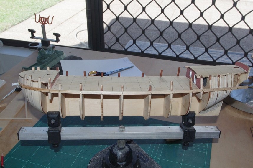
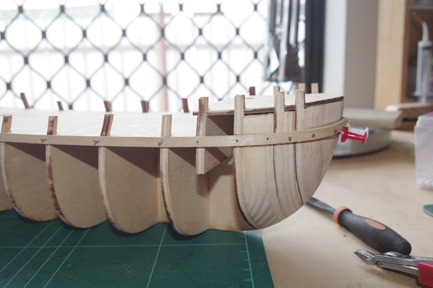
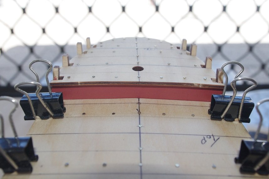
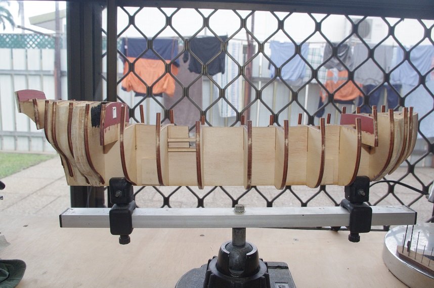
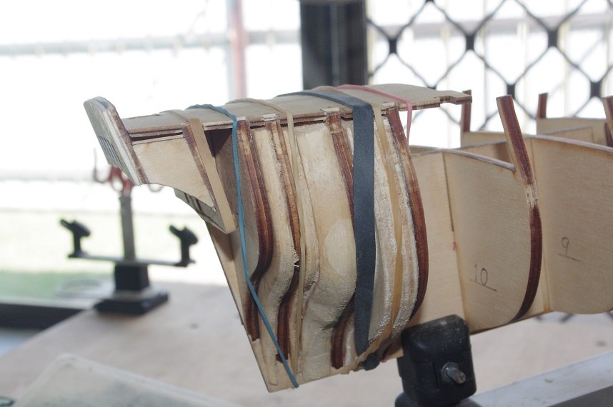
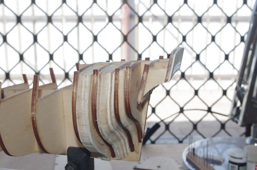
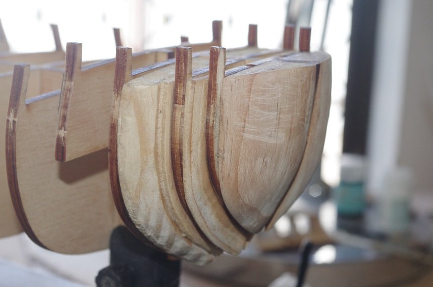
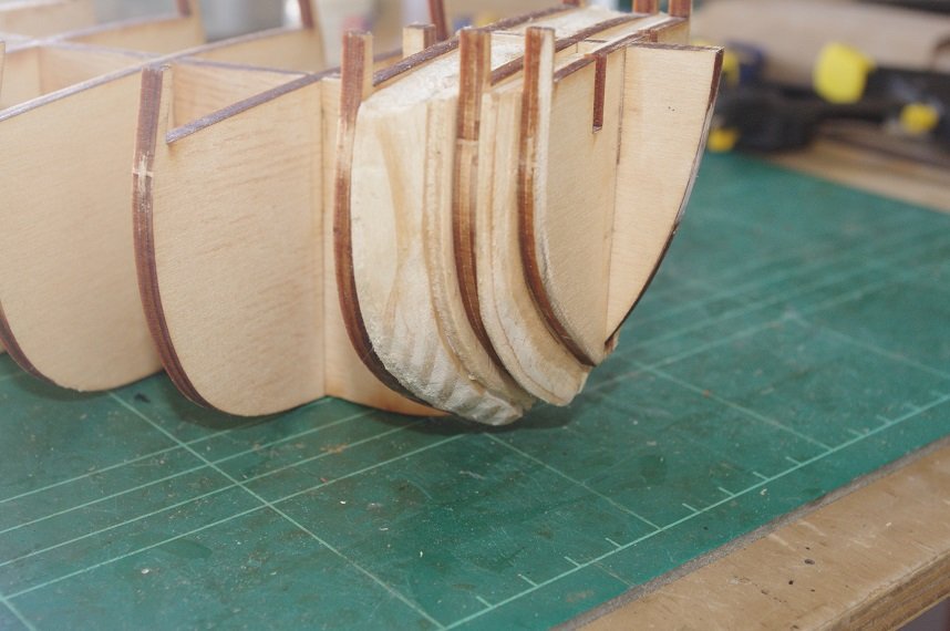
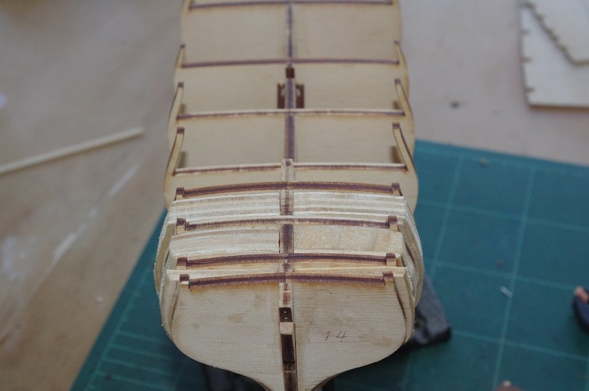
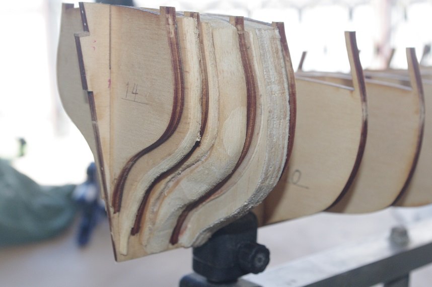
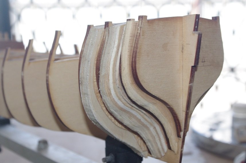
The fairing of the bulkheads and filler blocks has been completed, their not absolutely perfect and I will probably need to fine tune them in places as the planking progresses but I am happy with how it turned out and should provide a good base for the planks.
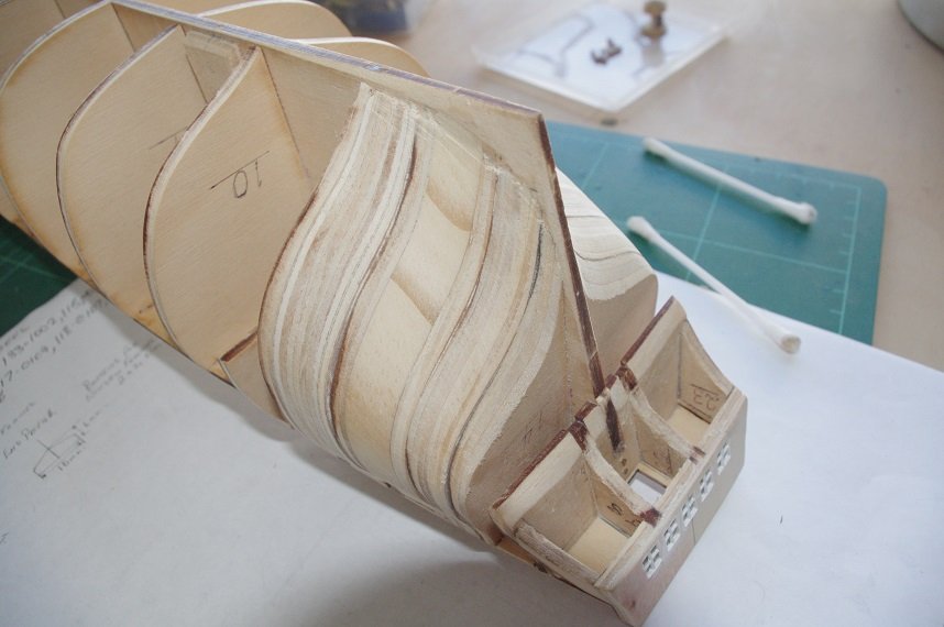
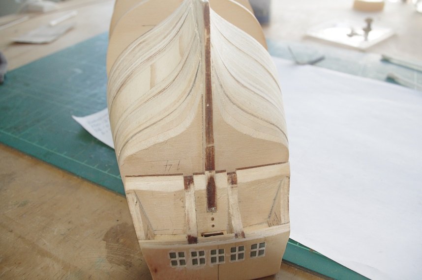
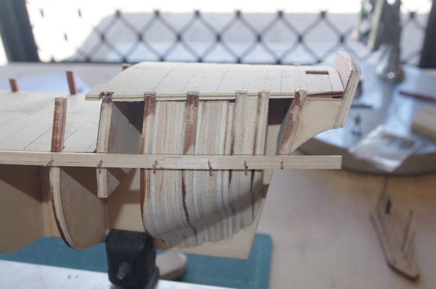
As can be seen at the stern there is quite a sharp bend required in the planks from bulkhead 14 down to the first bulkhead on the transom.
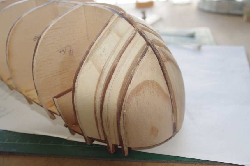
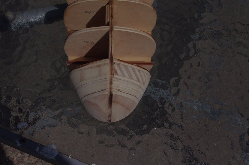
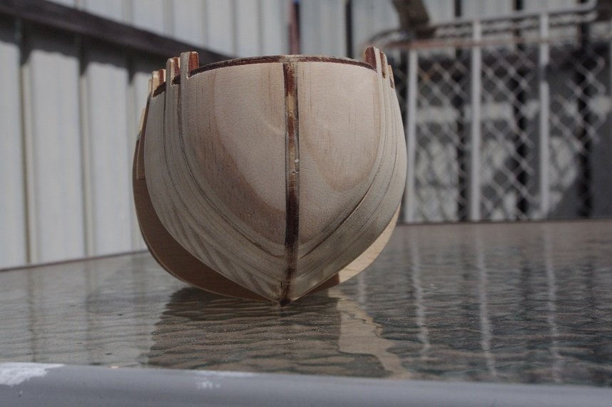
I think the bow turned out fairly well.
The next job is to lay the first planks port and starboard.
- Fernando E, GrandpaPhil, clearway and 1 other
-
4
-
-
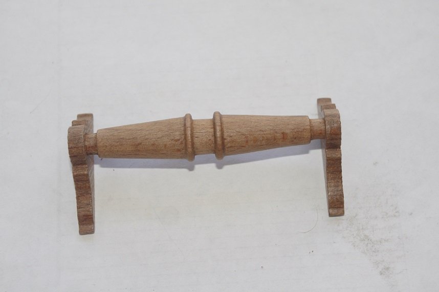
Thanks for the suggestion Keith but I have found a brass gear in my spares box that I am going to use.
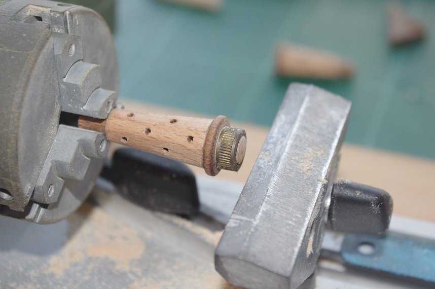
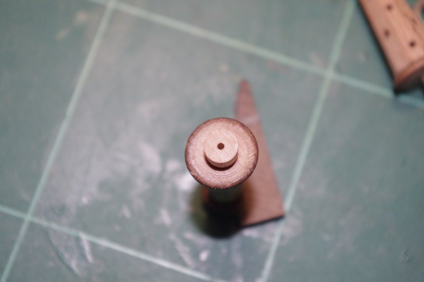
The holes for the hand spikes were marked onto the flats and drilled with a 1.5mm drill.
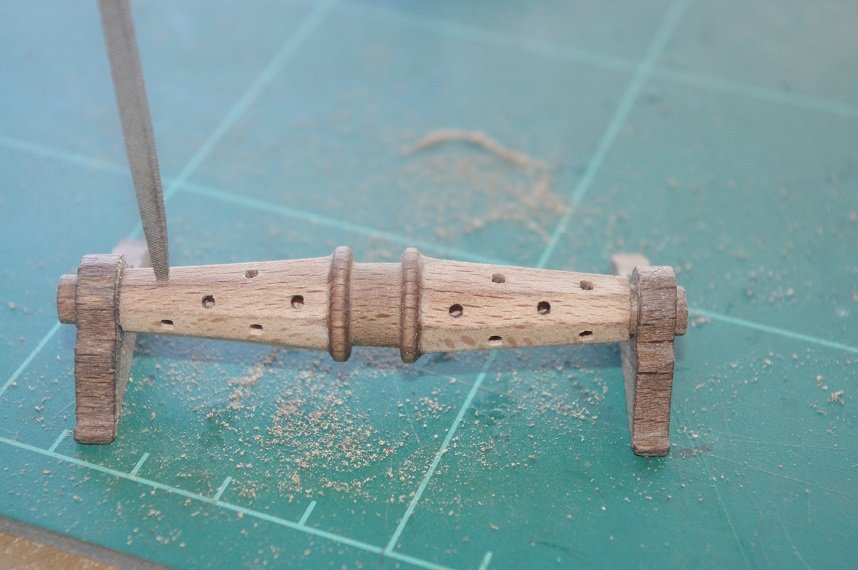
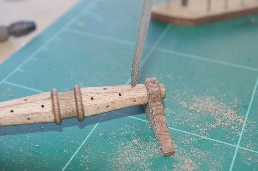
I then gently tapped in the point of a square needle file to square the holes.
The pawl gear was the next part that needed to be fitted.
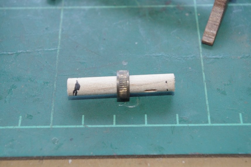
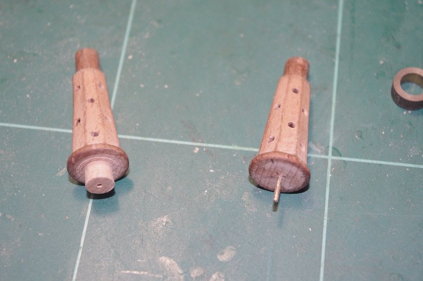
This brass gear was from a kit I started back in the '90s and never finished, the hull was damaged in a move and binned but I kept the fittings and all of the strip wood and dowel that was not used which has come in very handy over the years. The gear has an I.D. of 6mm and the centre part or the windlass has a diameter of 9mm so it will need to be turned down. I cut the windlass in half at one edge of the centre spindle and turned it down in my lathe to fit the gear.
A 1.1mm hole was drilled into the centre of each half so that a 1mm brass dowel could be used to join them back together.
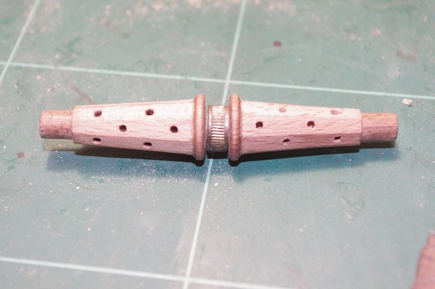
The next step will be to modify the supports to stand upright along with continuing to fair the hull.
Thanks for looking and the likes.
All commments welcome.
- egkb, clearway, BLACK VIKING and 4 others
-
7
-
Hi Stuglo, the paint I used was Tamiya X-14 Sky Blue enamel and did not use any primers or sealants. Being and oil
based paint as opposed to a water based paint might be the difference, it covered the black fairly well. I don't know if they were ever painted black.
Hope this helps.
-
Hello All,
I have started fairing the hull and it is taking a bit longer than I anticipated but I am taking time with it to get it as good as I can. In between sessions of hull fairing I have started to construct some of the deck furniture, this will also give me something to do during the planking process while the glue is drying.
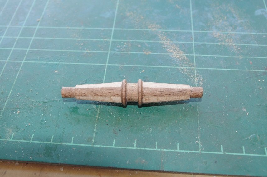
The first part I am making is the windlass, the kit supplies this as a three piece part (two supports and the windlass drum) and say to assemble it and fit it to the deck as is.
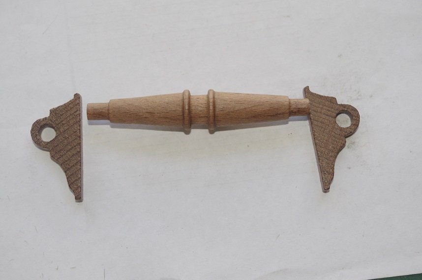
While the part is of reasonable quality it is a little plain so it will be modified to look a little better, my other problem is where the windlass is to mounted. The instructions have it mounted on the main deck adjacent to the front bulkhead.
This not only takes up a lot of deck space, which would be important on a supply vessel but also looks wrong to me. Looking at the plans in the maritime museum and the photos of the model in the powerhouse museum the windlass drum was mounted close to the edge of the foredeck with the supports being bolted to the timbers of the frame that supports the end of the deck. Something like in the photo below.
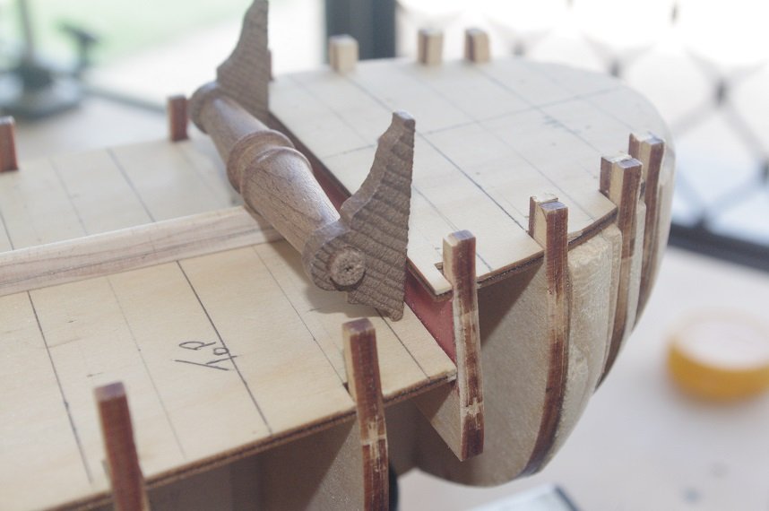
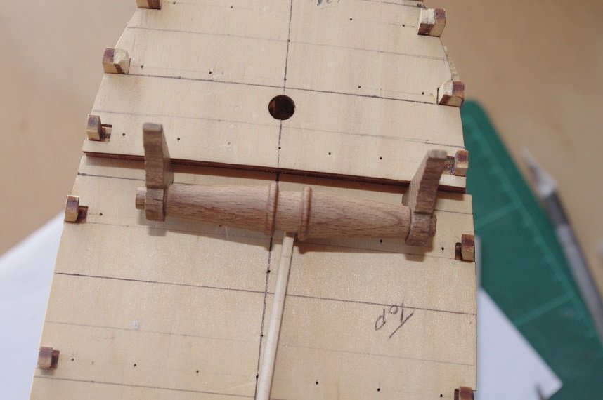
This is how the windlass will be mounted. I will modify the supports and let them into the foredeck so that they fit flush against the bulkhead, the fore fife rails, pawl and belfry will be incorporated into this area as well.
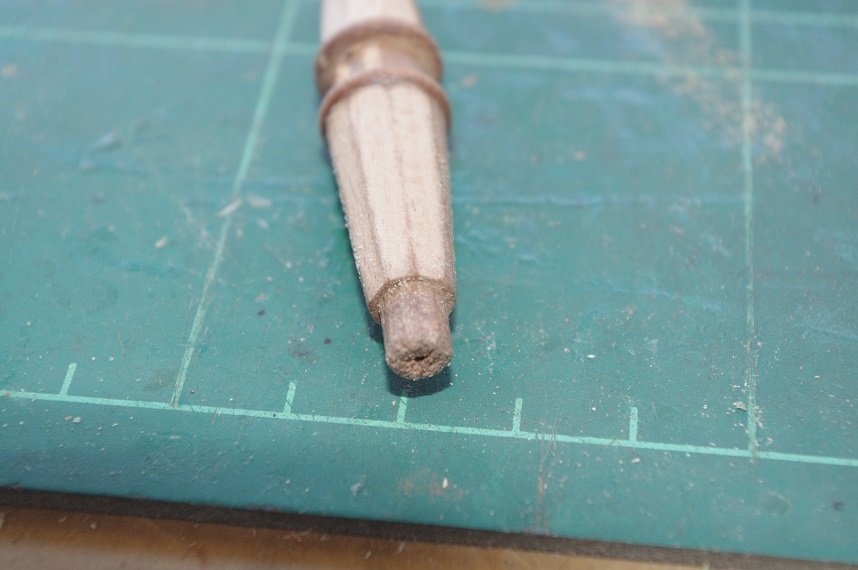
I have filed an octagonal shape to the windlass drums on either side of where the pawl gear will mount. These will be drilled and squared to take handspikes to turn the windlass.
Thanks for looking and the likes.
All comments welcome.
-
Looking good Scott, I hope the carpet monster didn't gobble up any of your spilled parts!
-
Thanks Keith, that sounds like a good idea I might do that for added security.
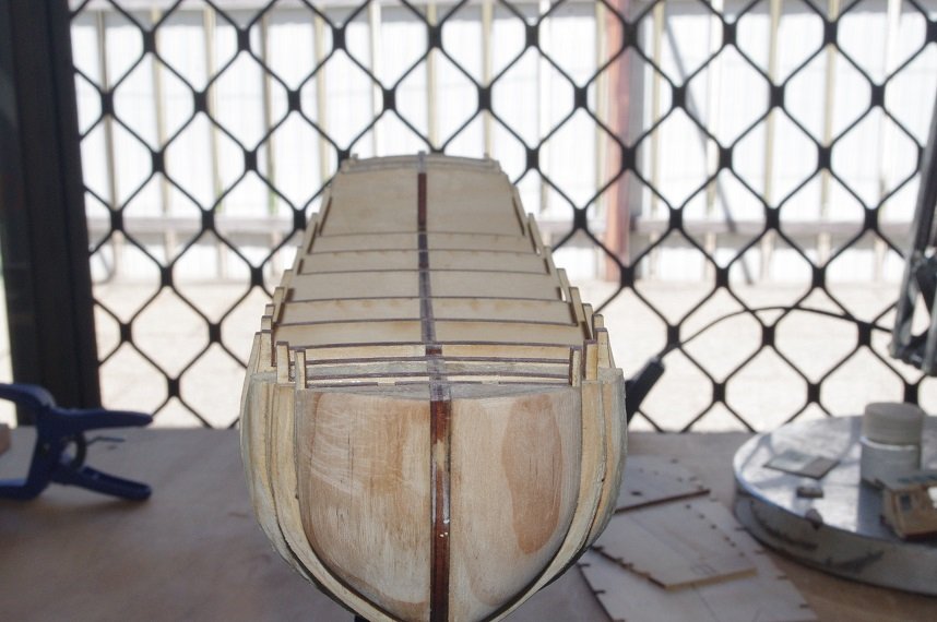
The fore deck and quarter deck have been fitted.

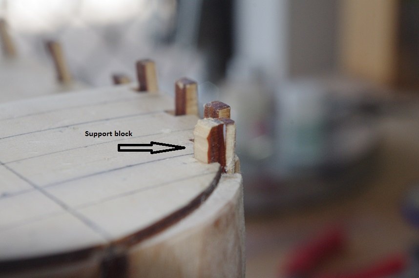
After fitting the fore deck I noticed a large gap between the horns on the bulkheads, which will be used to form the shape of the bulwarks, and the deck profile, so much that when the fairing of the bow is completed the horns on the first two bulkheads will almost completely disappear. The area marked in red in the photo below shows the material that needs to be removed from the bow filler blocks.
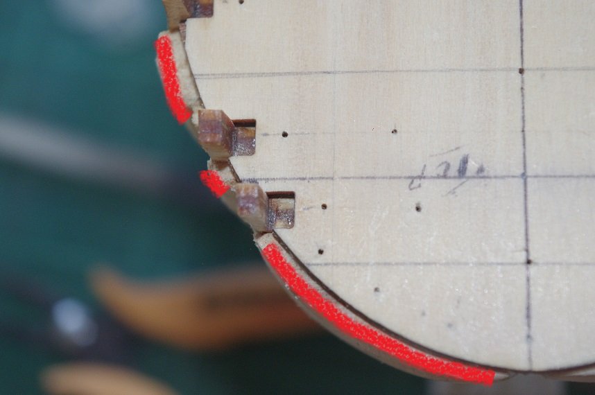
To overcome this I glued some 4mm ply to the horns on the first three bulkheads, once the bulwarks are formed these will be cut off.
Thanks for looking and the likes.
Comments always welcome.
- Tompslattery, GrandpaPhil, egkb and 4 others
-
7
-
Hello All,
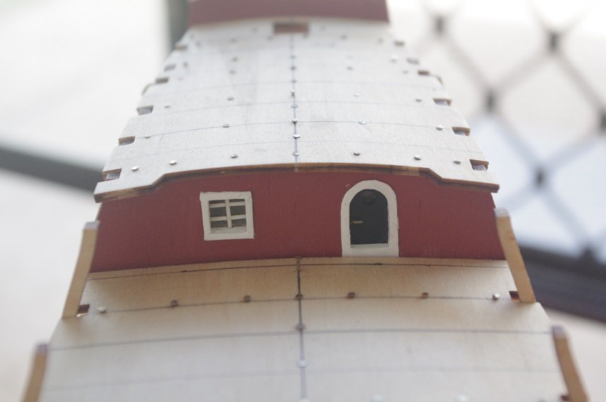
The aft cabin bulkhead has been completed and installed. Before it was glued on I painted two areas of bulkhead 11 black where it may be glimpsed through the window or door.
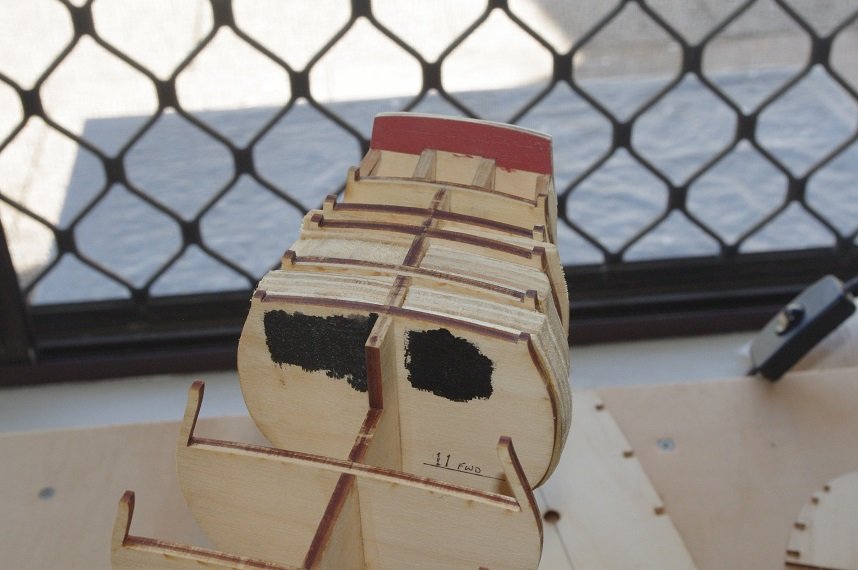
The bulkhead was then glued on.
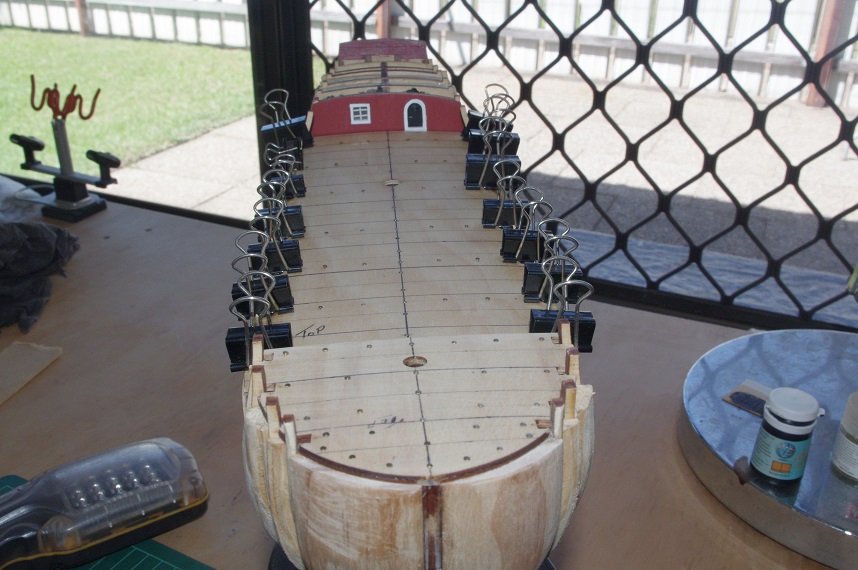
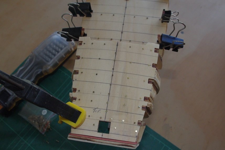
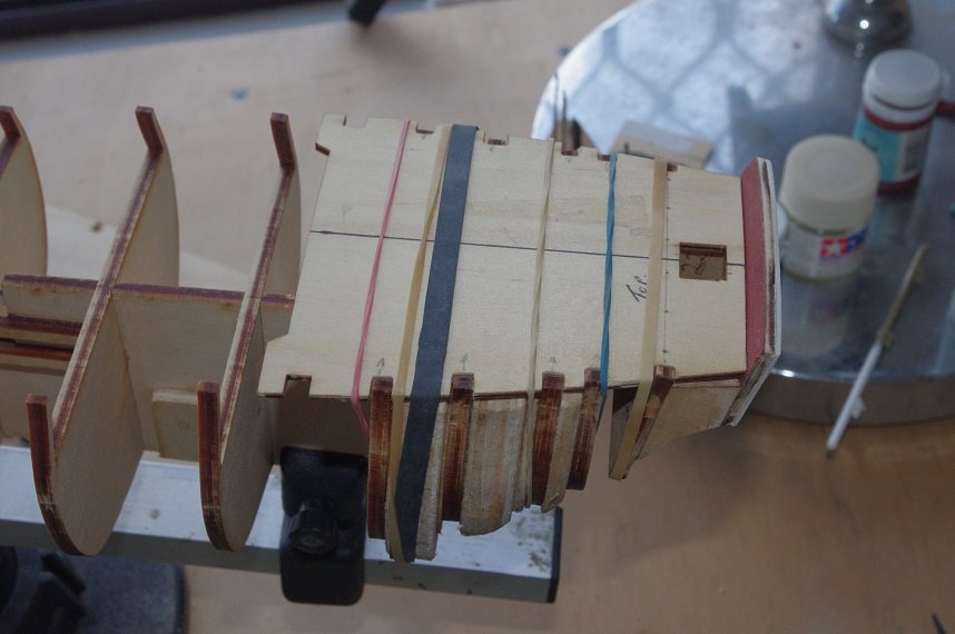
The decks were test fitted and required minimal adjustment to the slots to let them sit down onto the bulkheads. As can be seen in the photos there is a significant curve in the bulkheads especially on the quarter deck and with the decks being made of 2mm ply will need to be pinned securely to the bulkheads while the glue dries, so nail holes were marked onto the decks.
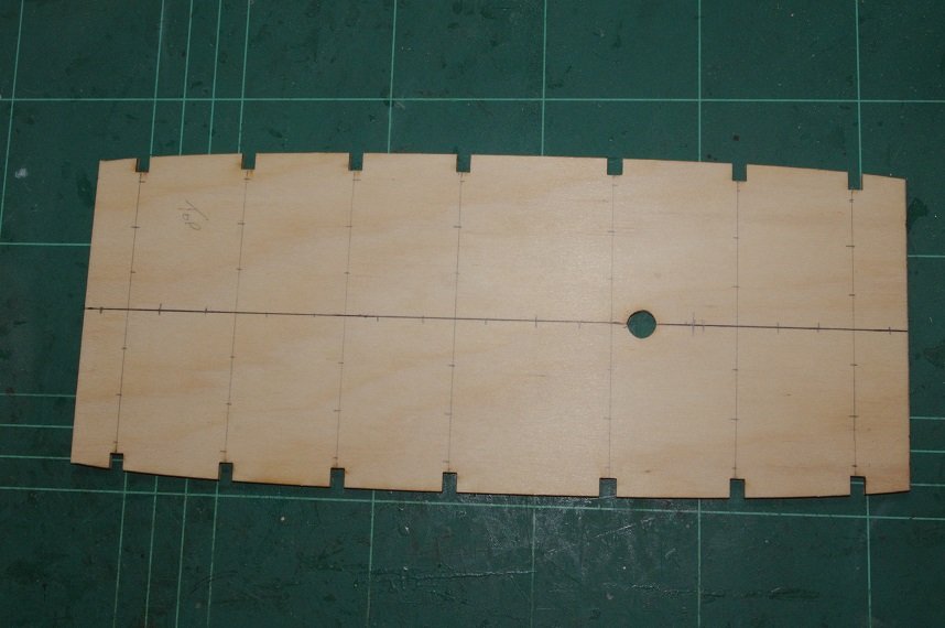
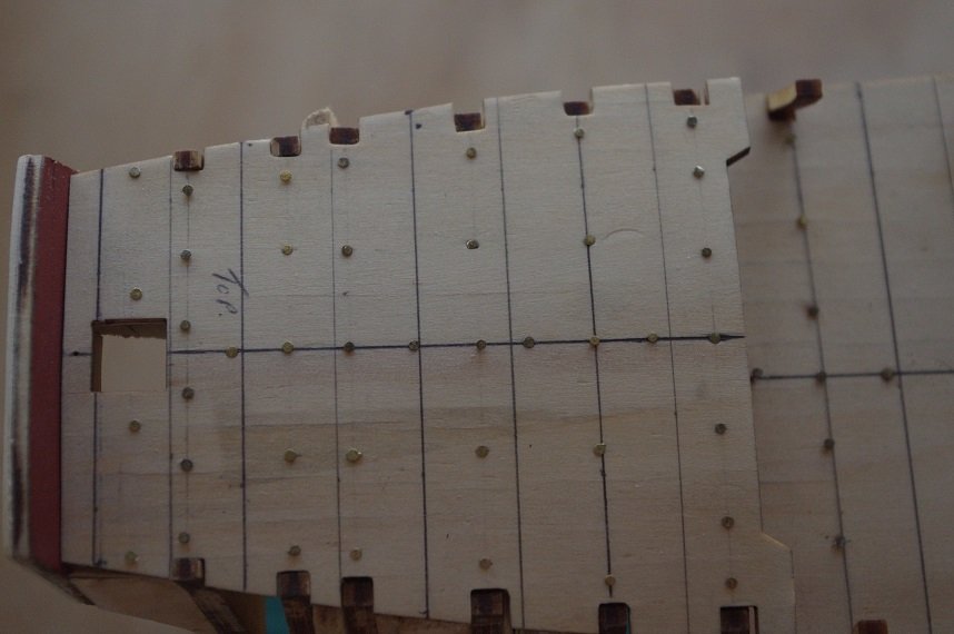
The fore and quarter decks were similarly marked and then drilled with a 0.65mm drill to take the 0.75mm nails that will be used. After that was done the decks were marked for the planking pattern. I am going to use a 4 butt shift and have worked out with the deck length that the planks will be 100mm long, a margin plank (5mm wide) will be fitted at the fore and aft end of the main deck and at the aft end of the quarter deck, with this marked spaces of 25mm were measured from the front of the fore deck these will represent the main beams for the butts to land on (they are the dark pen lines in the following photo). The fore and quarter decks were also marked.
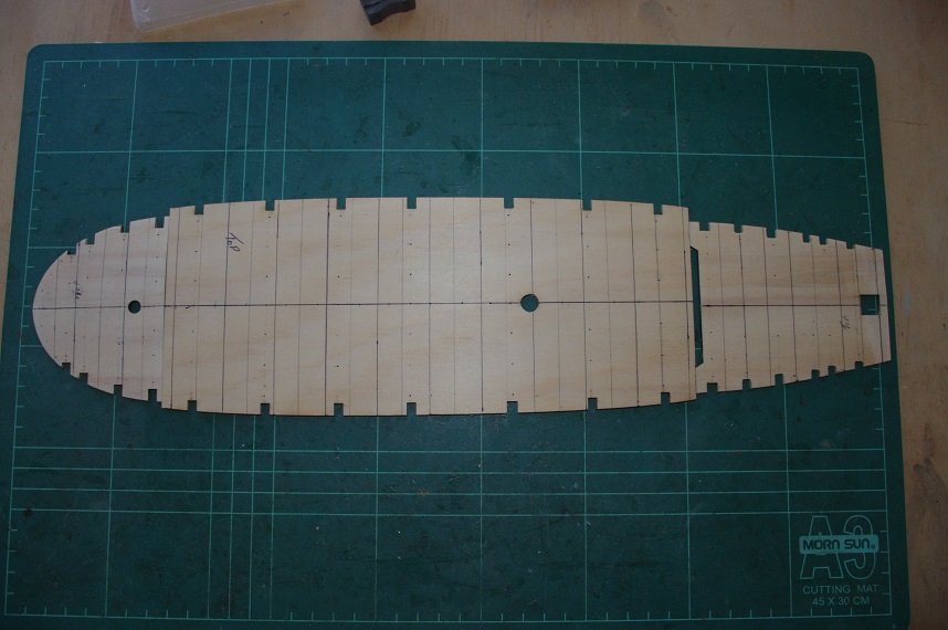
The light pencil lines in between the pen lines are for the intermediate beams which I am not sure whether or not I will use for trunnels. I will wait and see how it looks after I have added trunnels to the planks along the main beams. These lines will also be used to locate the position of the uprights which will be glued between the deck and the cap rail and they will be transferred to the outer hull so that I can use them as a reference when the second planking is laid as this will be in scale lengths also.
The nails were tapped into the main deck
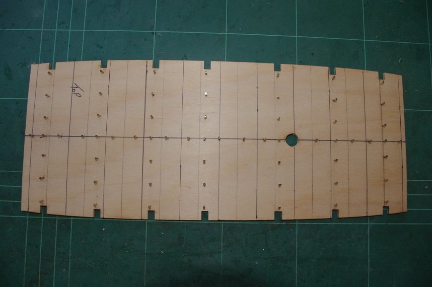
and it was glued to the false keel and bulkheads.
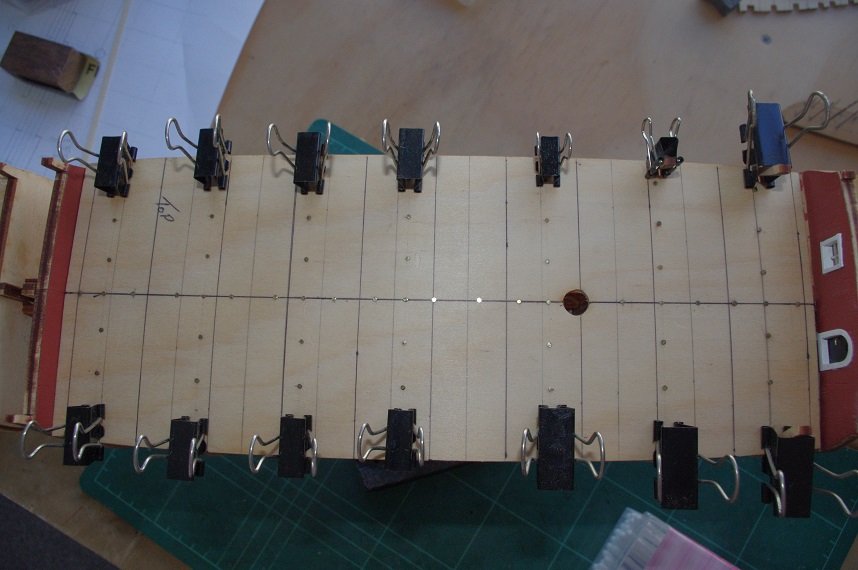
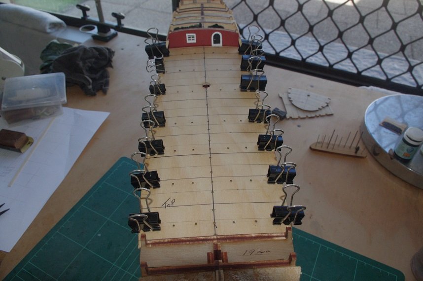
The assembly has been was set aside for 24 hrs to dry.
Thanks for looking and the likes.
All comments welcome.
- gieb8688, egkb, GrandpaPhil and 2 others
-
5
-
-
-
-
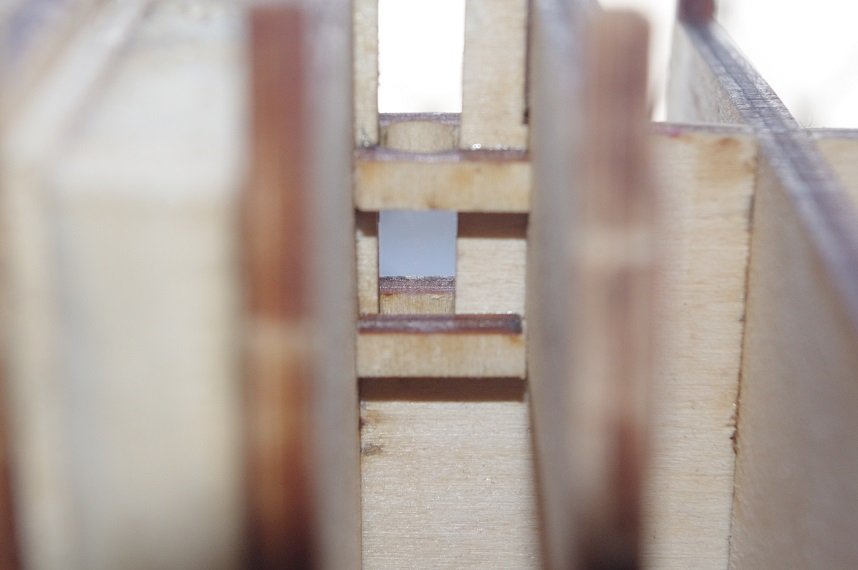
The mast supports for the fore and main mast were made from the parts of the ply sheet that was in the slots of the bulkheads.
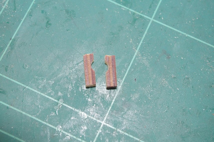
They were shaped with a round file and glued about halfway down the slot for each mast as the deck will support them at deck level.
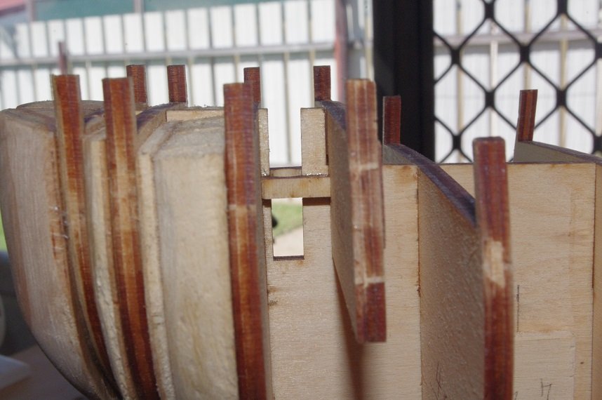
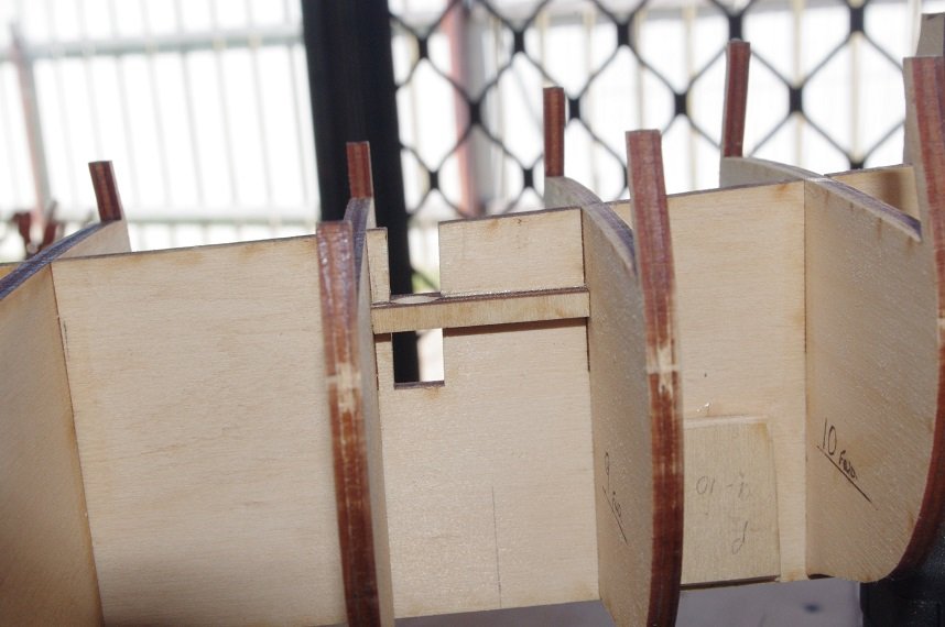
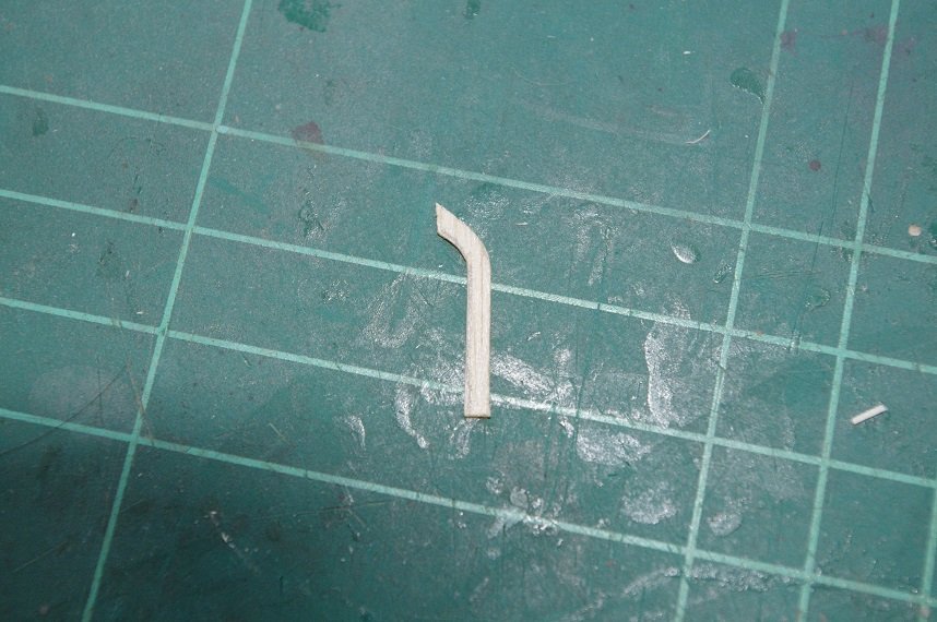
I decided to make a 'step' for each mast by leaving the lower support square forming a 4mm wide slot at the base of the mast.
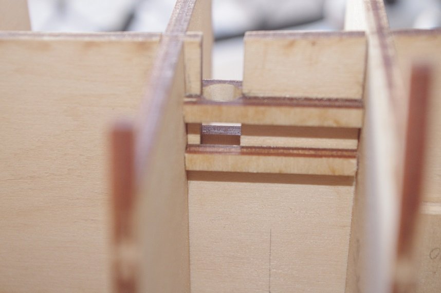
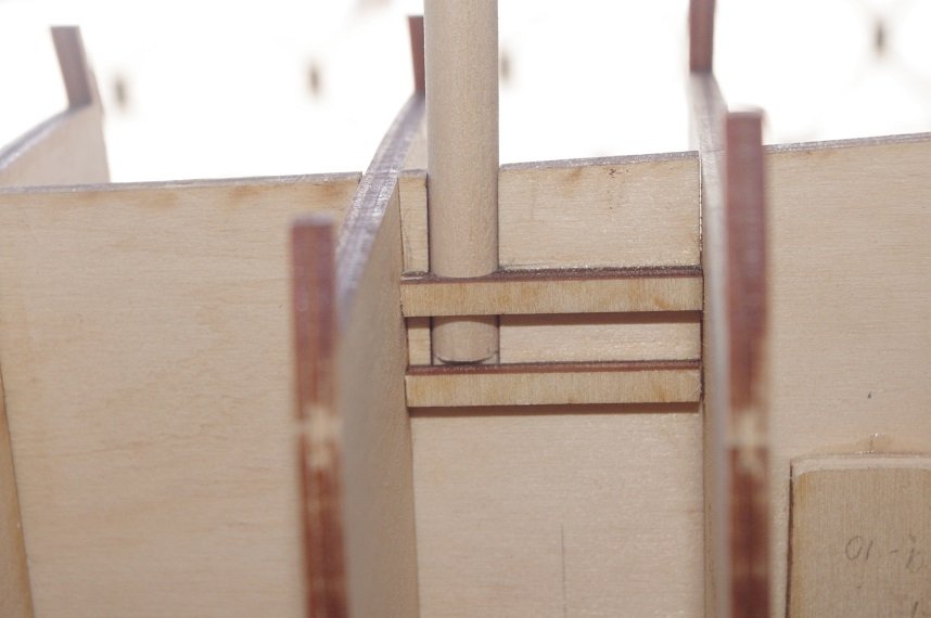
A step was cut into the base of the dowels.
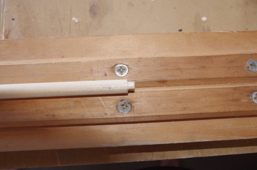
And they were test fitted into the slots.
Thanks for looking and the likes.
All comments welcome.
- GrandpaPhil, Fernando E, egkb and 5 others
-
8
-
Hello All,
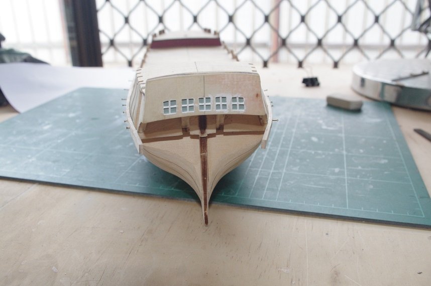
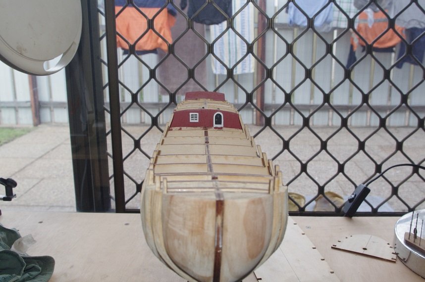
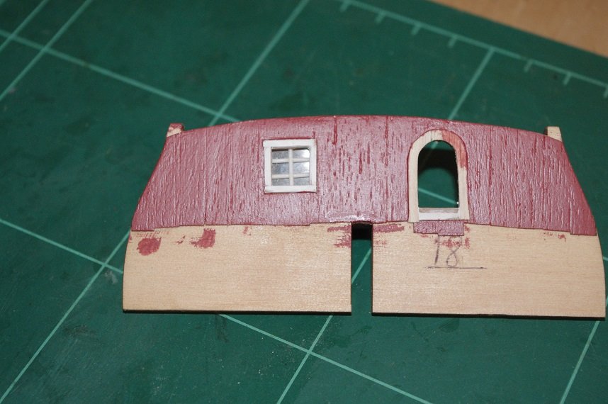
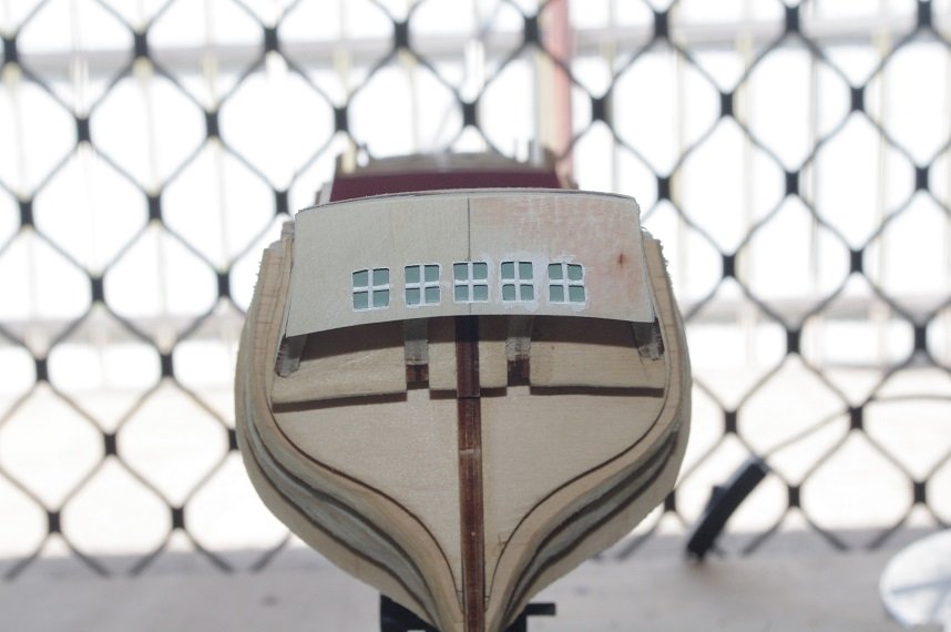
The stern cabin wall has been painted, the window and door frame still need to painted white.
The stern windows have been glued to the transom and the transom assembly has been glued to the false keel.
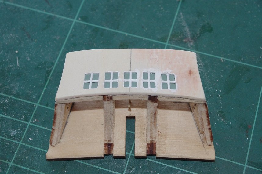
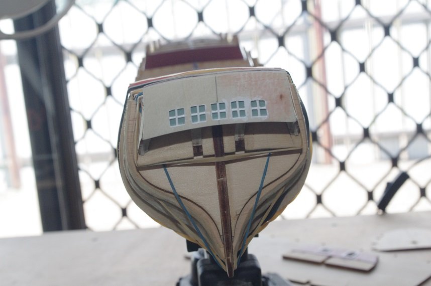
The only way I could think of to hold the transom square while the glue dried was to use the slots in the quarter deck to key it to the bulkheads already fitted. It was pinned to the keel and glued on using two part epoxy as recommended in the instructions for added strength as there is not a lot to glue it to.
The glue was left to dry for 24 hrs and then the deck was removed.
I have also made and fitted the mast supports. Photos in the next post.
- clearway, Fernando E, GrandpaPhil and 4 others
-
7
-
Very nice work on the handrails and bitts😊
-
-
Hi Captain Hook and thank you for your kind words and the link. This model is in the Power House Museum in Sydney it was built in the 1930's to commemorate the 150th landing of the first fleet. I think from memory it is 1:24 scale and the same modeller also built a 1:24 scale model of the HMS Sirius. I don't know whether they are still on display as I haven't been to the museum for quite a long time.
I have the link saved and will be using the excellent photos on it as a reference to the enhancements I am making to this model.
Bulkhead 19 has been glued on along with the bow filler blocks.
Some work has also been done on the aft cabin bulkhead, 2 pieces of 0.5mm timber were fitted to the into the front of the doorway to a depth of 2mm so that the door will rest against these when fitted from the rear. Two door frames were also cut from a piece of 0.5 x 5mm basswood.
The cabin window was made by setting some 0.5mm timber into the rear of the frame to a depth of 2mm and then placing a piece of acetate onto them and gluing the frames, made from 0.88 styrene rod, and then adding some more 0.5mm timber painted white over them to form the outer frame for the window.
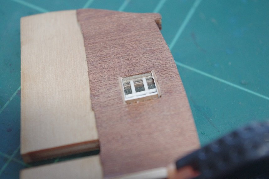
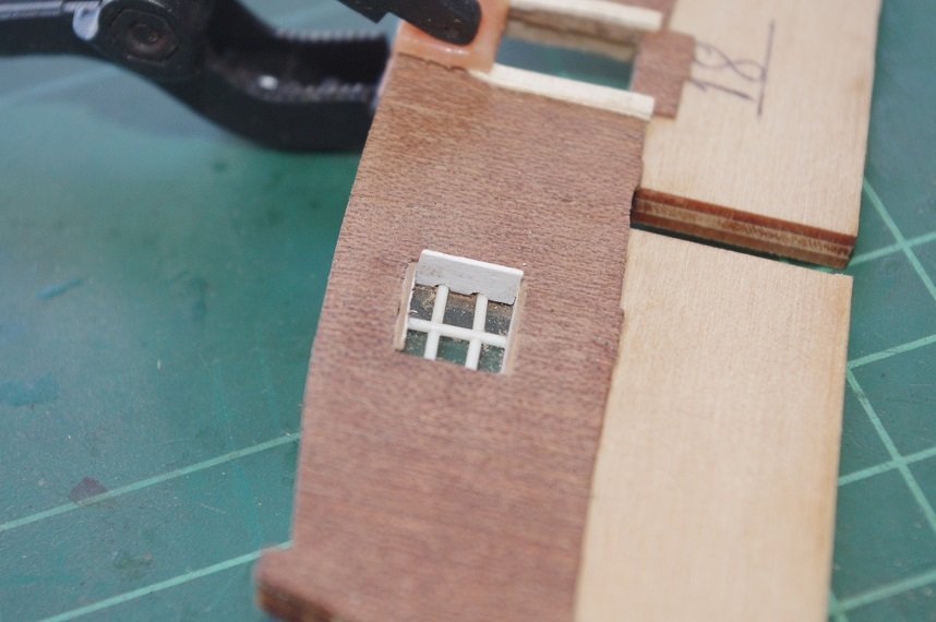
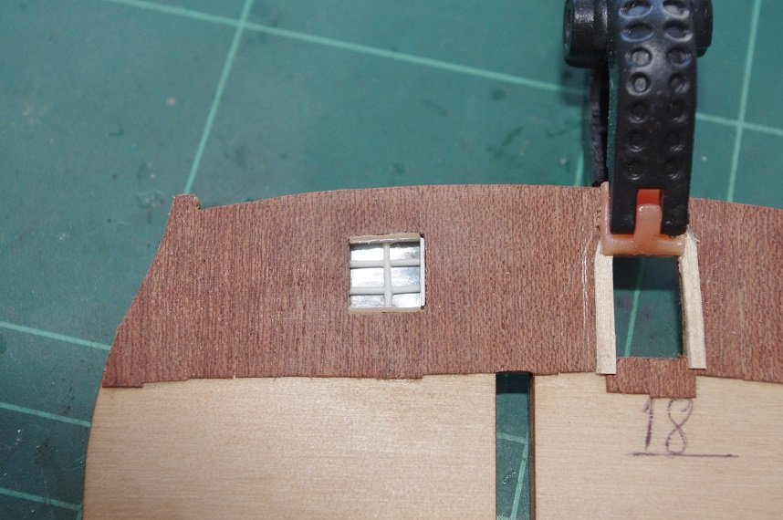
Another frame will be fitted around the window to hide the gaps.
Thanks for looking and the likes
Comments always welcome.
- clearway, gieb8688, captain_hook and 4 others
-
7
-
-
Thanks Keith, I think they will help give a smoother curve to the planks.
Hello All,
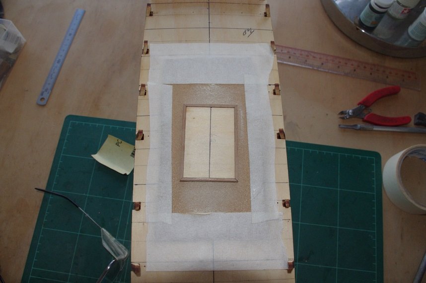
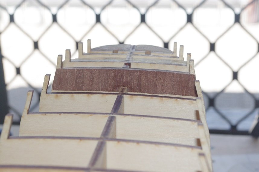
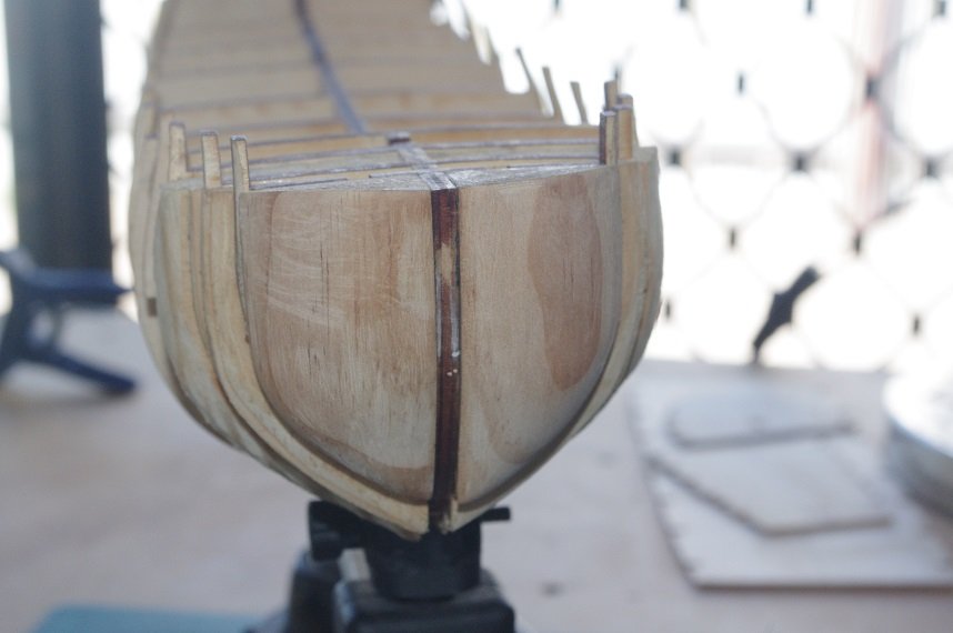
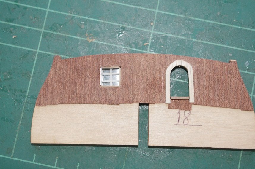
I have finished planking the fore bulkhead and the aft cabin bulkhead, I also added the planks to the inside of the transom.
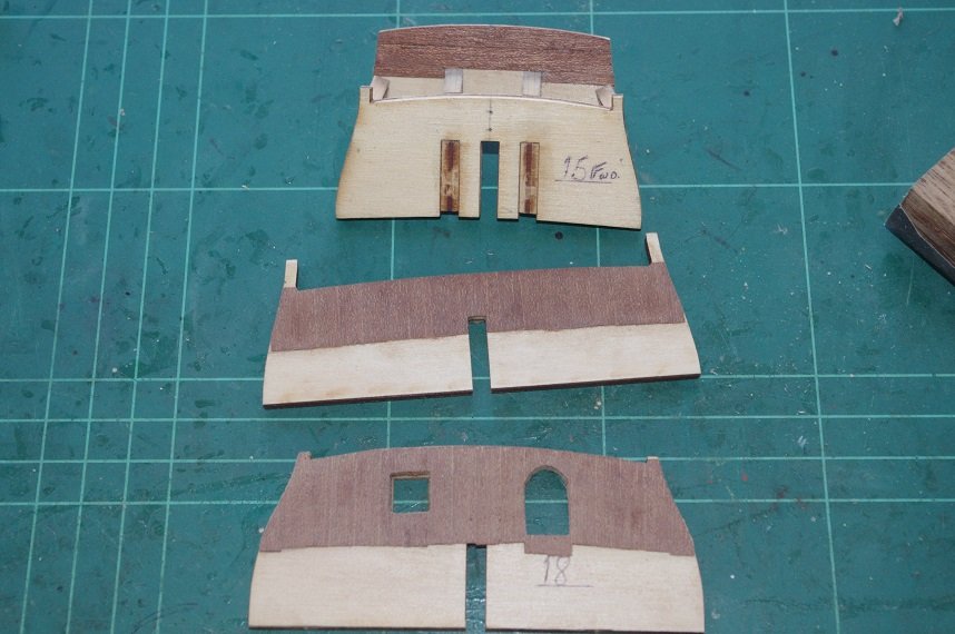
The doorway and window still need some work to be done to them before the window and door are fitted.
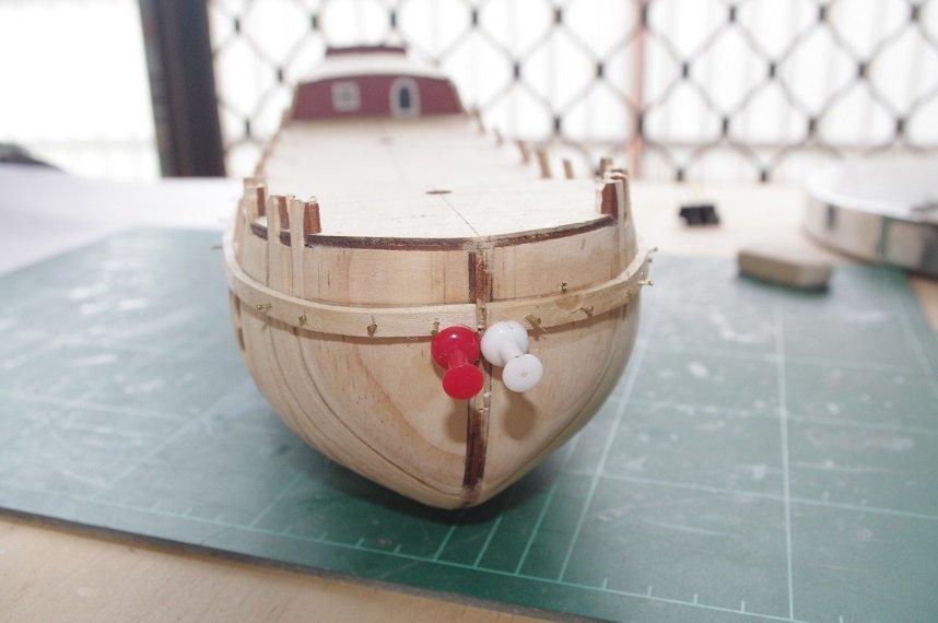
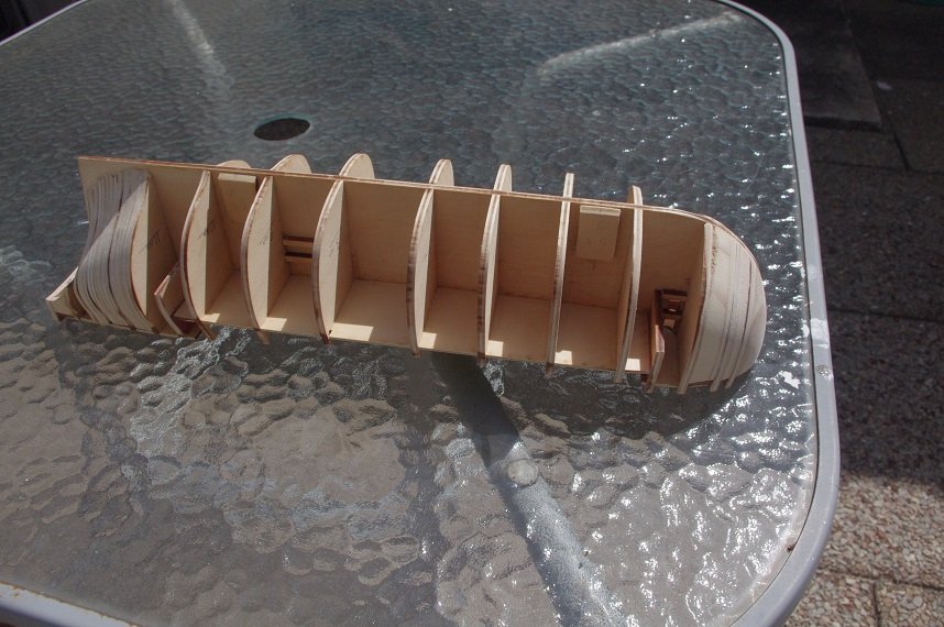
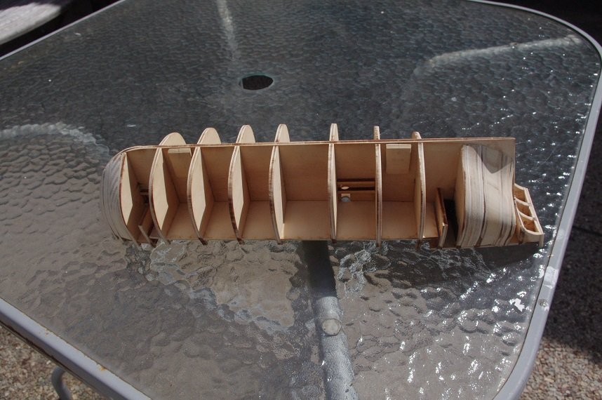
I have also decided to add some extra bow filler blocks in between bulkheads 1 and 2 and bulkheads 2 and 3.
These were cut from 3mm ply sheet and some 8mm pine board, they were roughly shaped and glued into position.
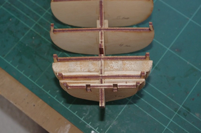
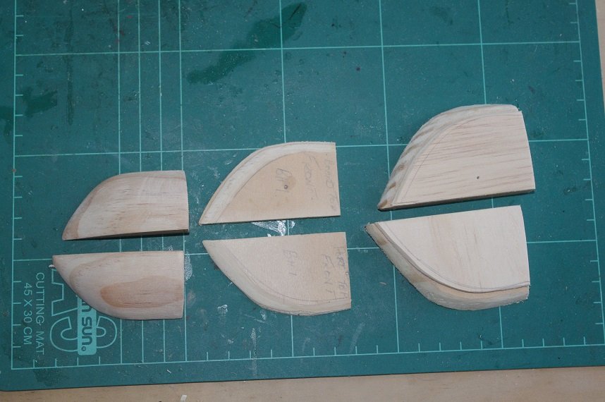
I have also made some filler blocks for the stern, these will fill the last three gaps in between the stern bulkheads.
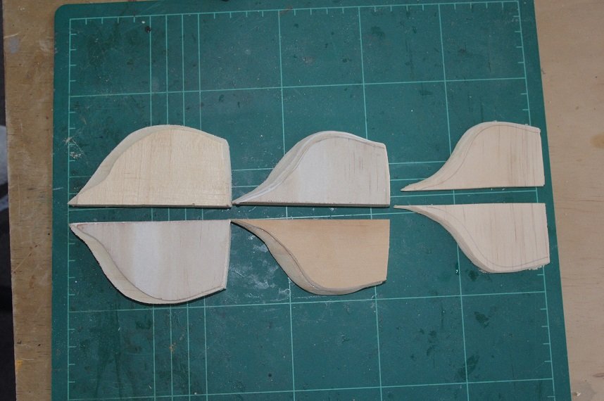
These were made from a combination of ply and pine board, they were also carved roughly to shape and glued into place.
When all of these are dry the final bow pieces will be glued on. I know this is probably a bit of overkill but I think once all faired in it will give me a nice smooth surface to lay the planks on.
Thanks for looking and the likes.
All comments welcome.
- egkb, clearway, GrandpaPhil and 4 others
-
7
HM Schooner Ballahoo by egkb - FINISHED - Caldercraft - 1:64 Scale - First Proper Wood Build
in - Kit build logs for subjects built from 1801 - 1850
Posted
Excellent work Eamonn, all looking good. I wish I could get my shroud seizings to look so neat.👍