HOLIDAY DONATION DRIVE - SUPPORT MSW - DO YOUR PART TO KEEP THIS GREAT FORUM GOING! (Only 13 donations so far - C'mon guys!)
×

Jeff-E
-
Posts
699 -
Joined
-
Last visited
Content Type
Profiles
Forums
Gallery
Events
Everything posted by Jeff-E
-
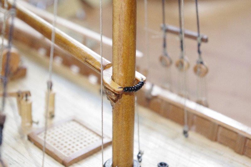
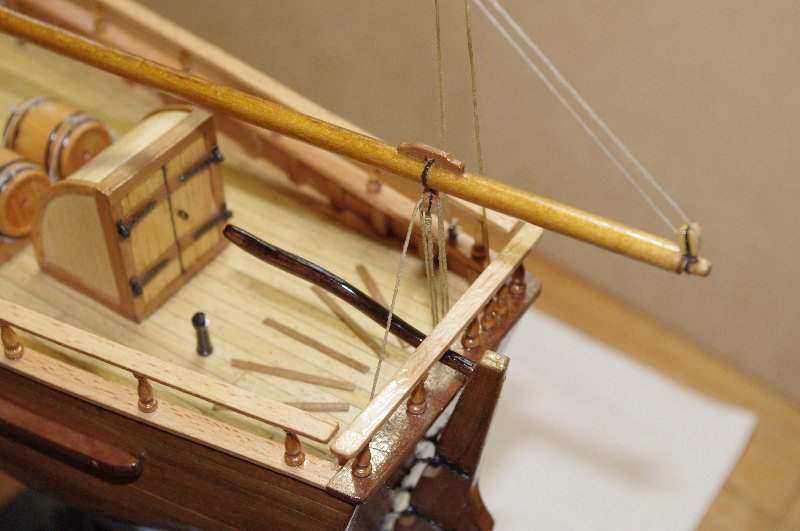
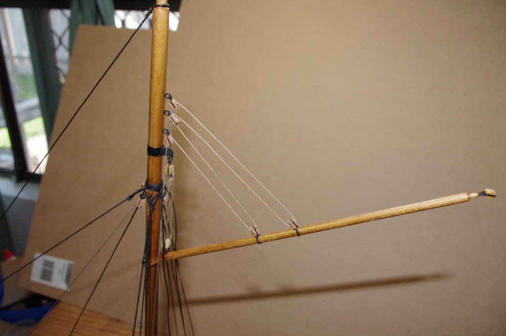
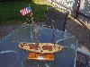
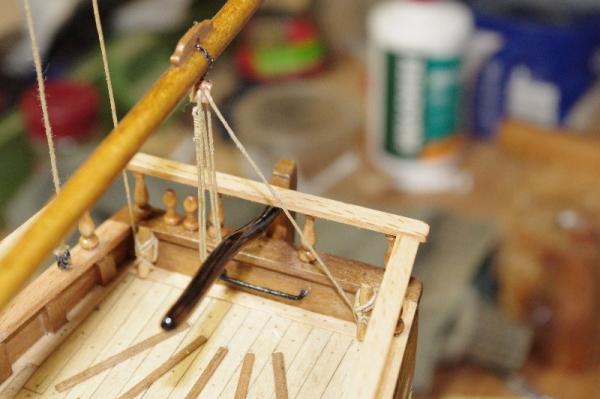
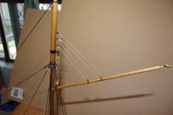
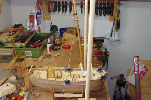
Hi All, The first picure shows another view of the gaff rigged. The next job was to fit and rig the driver boom; this spar only has two lines rigged to it they being the topping lift and the mainsheet.. The boom was attached to the mast with parrel beads and the jaws rested on the boom support fixed to the mast. The two lines were then rigged. The topping lift starts at a two hole block fitted to the mast at the shroud cleats and goes down to aone hole block fitted to the end of the boom and then back up through the two hole block and back down to the deck belaying off at the port side belaying pin. The mainsheet is rigged using two two hole blocks one attached to the boom and the other to a rail fitted to the transom the blocks are reeved together and the the line belays to the cleat on the port side of the transom.


- 98 replies
-
- 2
-

-
- norfolk
- modellers shipyard
- (and 1 more)
-
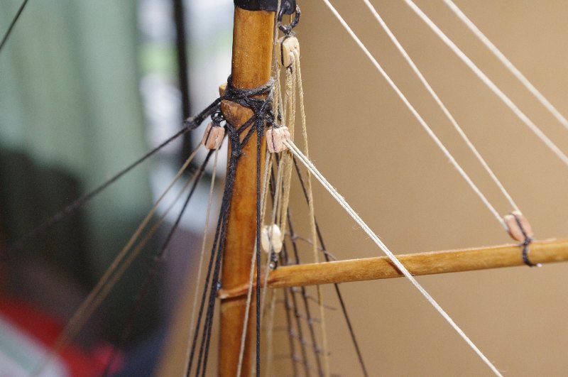
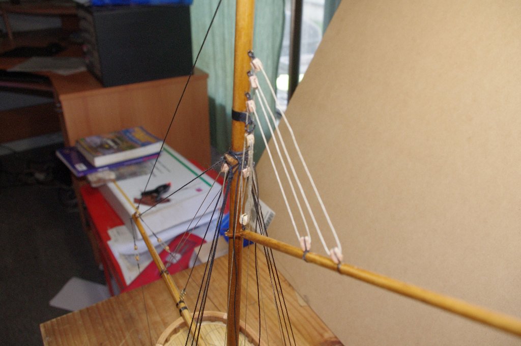
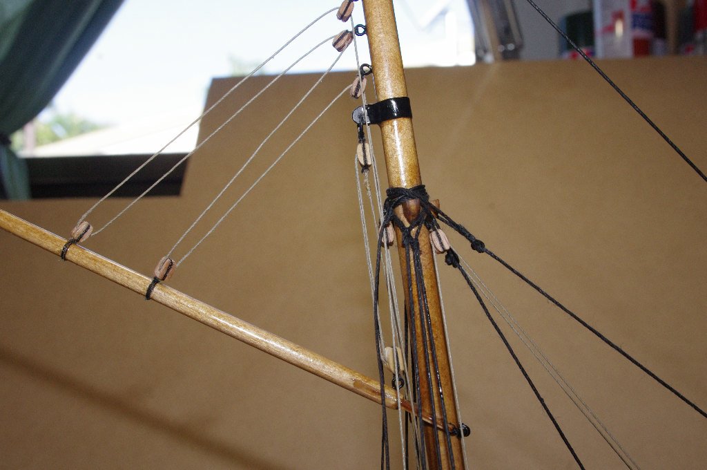
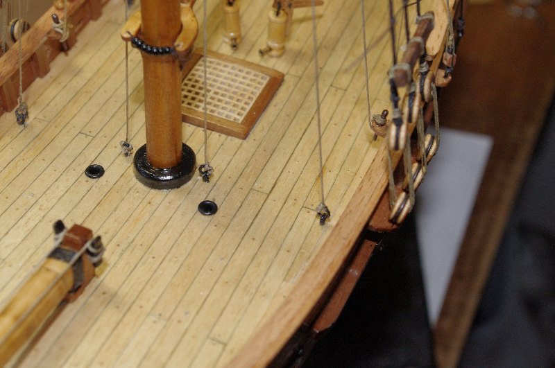
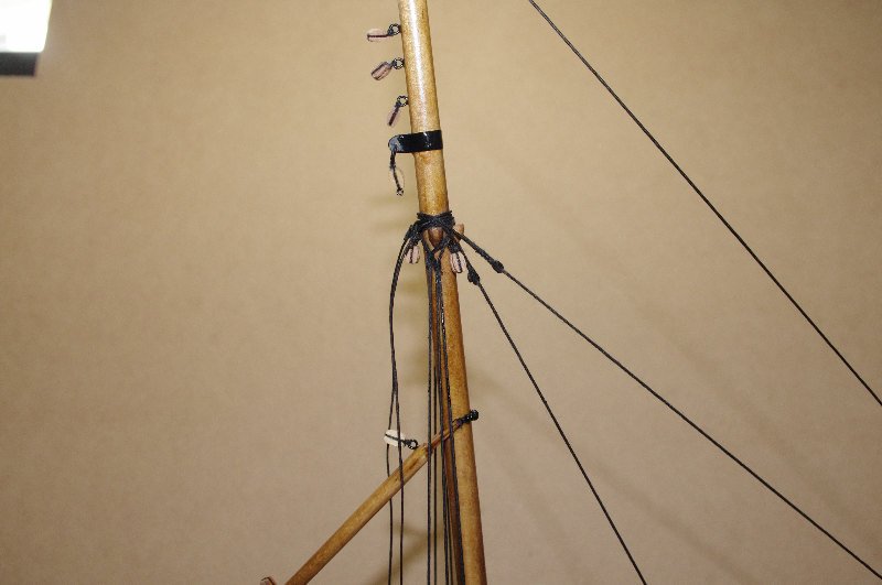
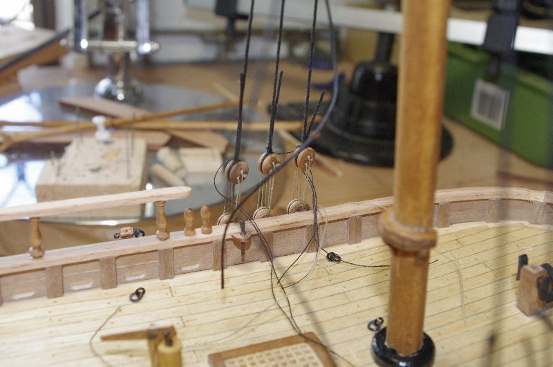
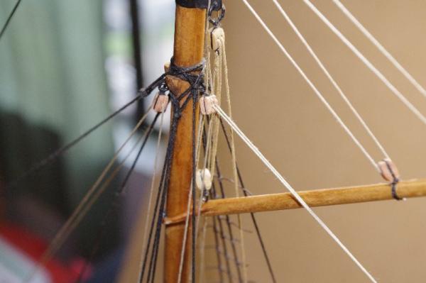
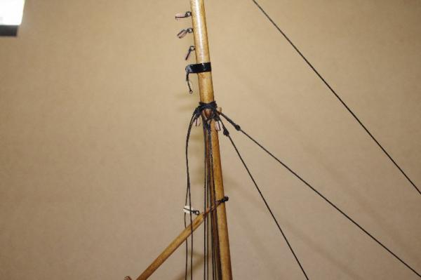
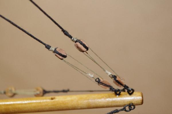
Hi All, My Next job was to rig the gaff. this consisted of 2 lines the throat halyard and the peak halyard. The throat halyard was rigged through two 2 hole blocks one attached to the strap on the mast and the to an eye pin near the jaws of the gaff it was then belayed to the starboard pin rail. The peak halyard stars at a ring bolt on the starboard side of the mast and goes through the three blocks attached to the mast and the two blocks attached to the gaff and then terminates at a ring bolt on the port side of the mast The last picture shows the belaying points on the deck. the peak halyard is belayed to the 2 eyebolts next to the mast, the throat halyard to the lefthand belyaying pin and the jib halyard to the 2 outer eybolts.


-
Hi ZyXuz, Thakyou for looking in and for your kind words
-
Hi Frank , Thanks for dropping in and for your kind comments. It was Danny's log that inspired me to build this kit and I was very lucky to have most of the planking done before the old site crashed as Danny's log helped me alot in working out the run of the planks, I am pleased with the result .The kit itself is of good quality; the laser cutting, timber strips and most of the supplied parts are very good quality except for a few minor issues which I believe have been rectified in the updated version I would recomend it to any one interested in building it.
-
Hi Danny, Thank you for your kind comments , it was your log on the old site that gave me the ideas to build her this way
- 98 replies
-
- 1
-
-
- norfolk
- modellers shipyard
- (and 1 more)
-
Hi Caroline, Wishing you a very happy birthday It is good to see you are reposting your log of this very beatiful model
-
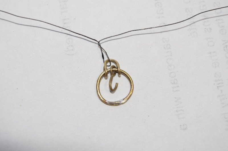
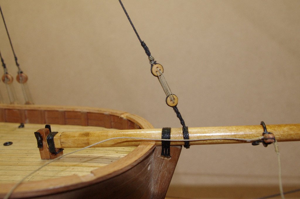
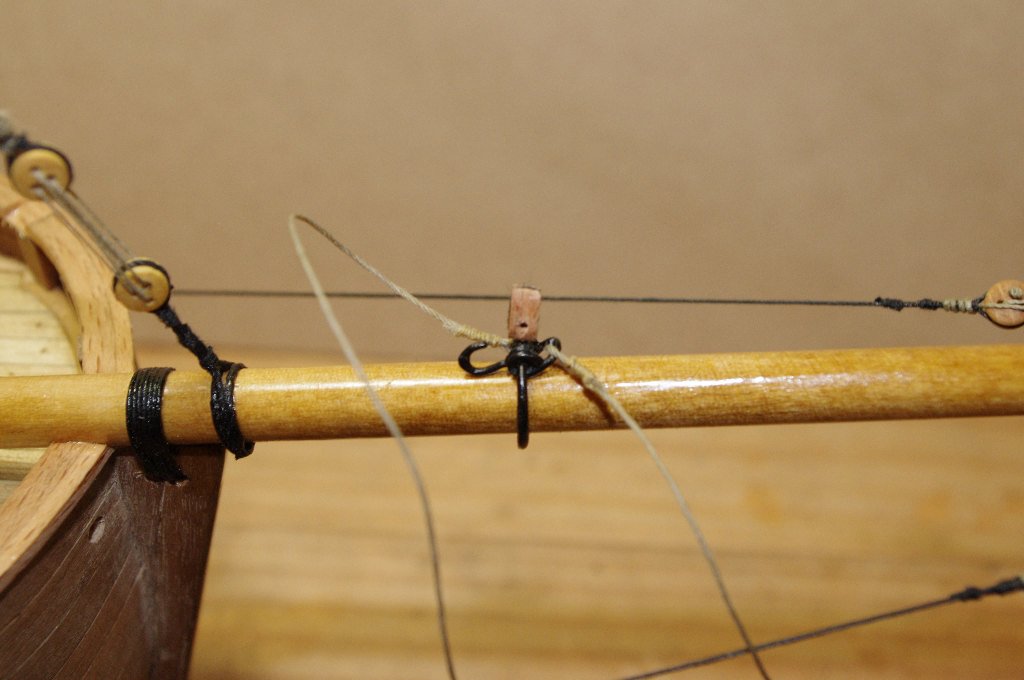
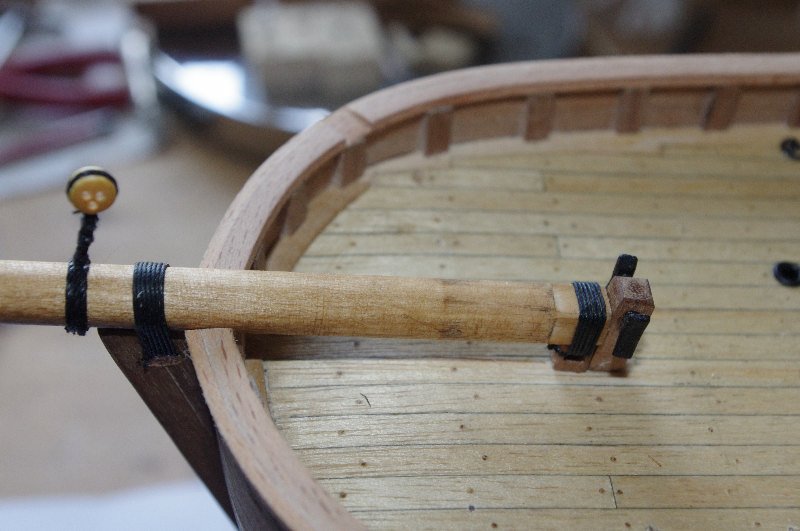
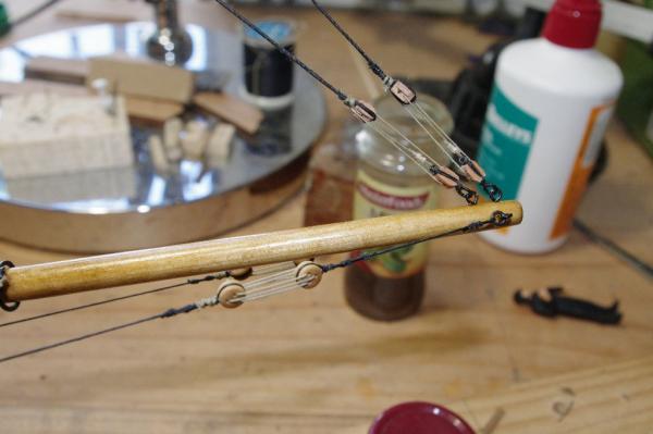
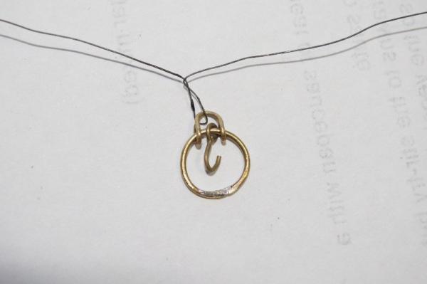
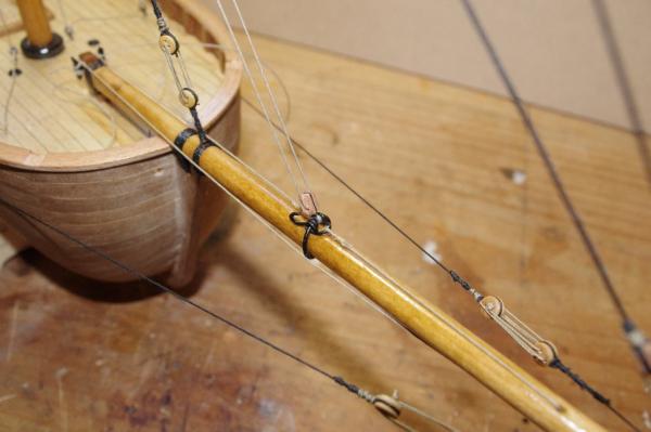
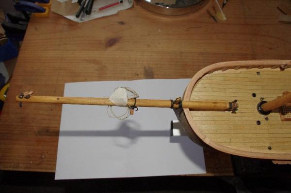
Hi All, That takes care of the standing rigging for now as I will rig the ratlines after te running rigging is complete. The first picture is a clearer shot of the bowsprit guys or stays I'm not sure of the right term The next set of photos are of the jib traveller. The first one is of the traveller before it was fitted to the bowsprit It differs from the instructions as it has a 'D' shackle for the outhaul line and a hook which would attach to the bolt rope of the sail a single hole wooden block was added after it was painted and then fitted to the bowsprit before attaching it to the hull. The next three photos show the jib traveller rigged. The outn haul line belays on the othehaul line is rigged through a hole in the end of the bowsprit and is belayed on a cleat on the headstock not as the instuctions tell which is to terminate at an eye pin halfway down the stempost , the inhaul line belays on the other cleat on the headstock and the jib halyard is rigged through the single block on the traveller and up through 2 single blocks attached to the mast and then down to the belaying points on the deck


- 98 replies
-
- 1
-
-
- norfolk
- modellers shipyard
- (and 1 more)
-
Hi David, Thankyou for looking in at my log and for your kind comments
-
Thank you very much Brian
-
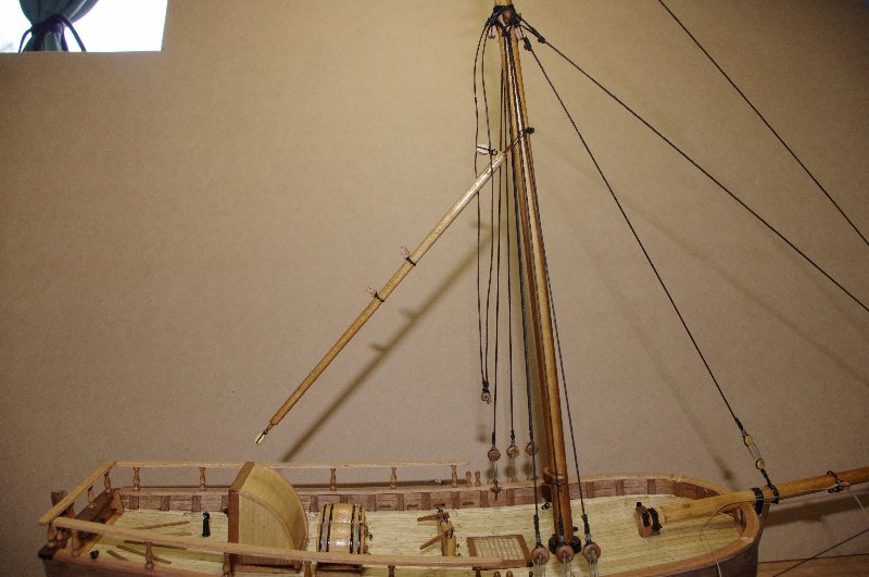
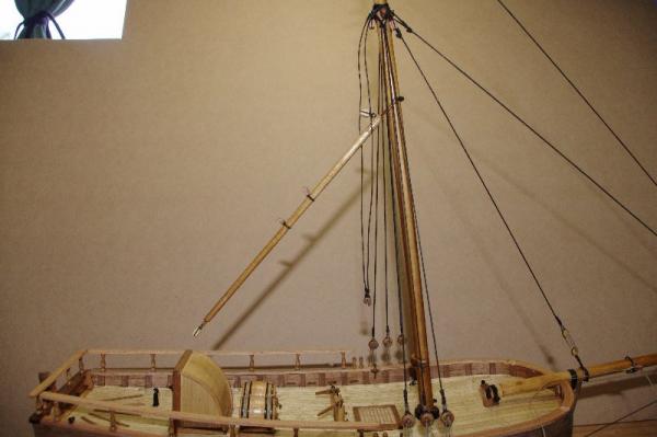
The stays were then rigged to the model Also rigged in the first picture are the bowsprit guys As you can see in the pictures the gaff has also been attached to the mast this will be rigged later The two lines hanging down at the rear of the mast are the backstays which will be rigged after the running rigging is completed.

-
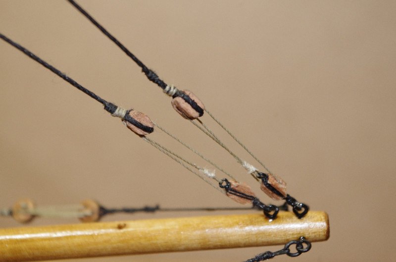
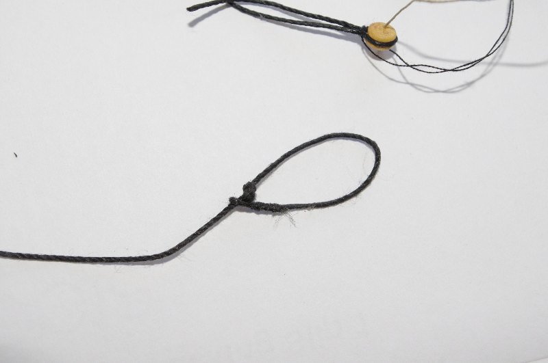
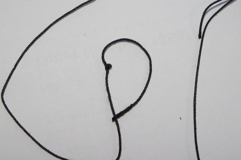
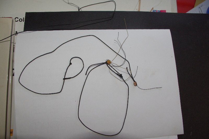
The next lines to be rigged are the forestay, fore preventer stay and fore topmast stay. these were all to be attached to the mast by looping the cord around the mast and siezing it. I used this method for the fore topmast stay but decided to use a mouse and eye for the other 2 stays. To make the mouse I simply tied an overhand knot in the rigging cord about 90mm from one end and then siezed a small eye in the end of the cord. I got this idea out of Keith Juliers book 'Period Ship Kit Builders Manual' I have since come across what I think will be a neater knot for the mouse; a simple stopper knot which I will try on my next model


-
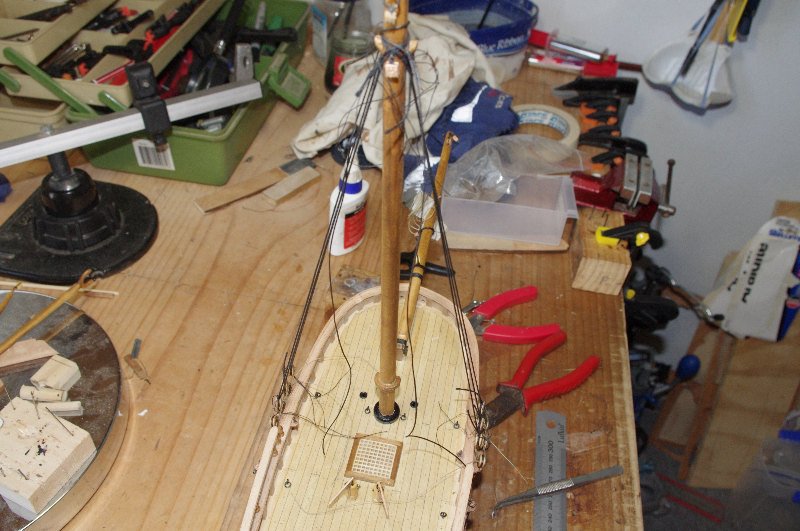
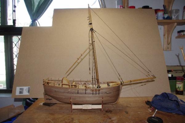
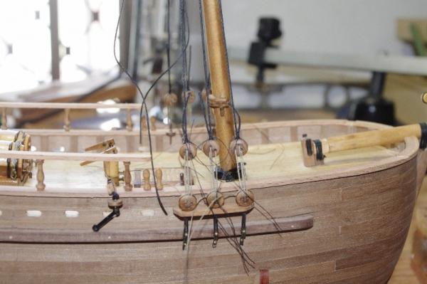
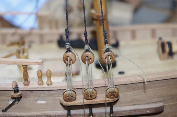
Hi All, Well thats about it for the actual hull constrution and fittings; I still have to fit the winch, catheads, anchors and the tiller but I will leave them until the the rigging is completed as they will probably get in the way and may be broken. So on with the rigging . The first lines to be rigged are the shrouds; there are only three each side on Norfolk so it was one pair and one single for each side. I made a wire gauge to keep the deadeye spacing even and then reeved the deadeyes. I would like to warn anyone building this model to measure out all your rigging lines very carefully as the kit only supplies just enough rigging cord for the process; in one case not enough when it came to the standing rigging there is approximately 3.2metres of riggnig using 1mm black cord and they supplied 3metres . I ran out of all sizes before all the lines were rigged. Fortunately I had spare cord from other kits to finnish the job altough they were not the exact same diameter or colour but were close enough to finnish the job.


-
Hi Slog, She's comming along well . I like your attention to detail by adding the extra bits that the kit does not supply
-
Hi Brian, Yes I have found a little time to make some progress on the build over the weekend. Hope to get some more done tomorrow.
-
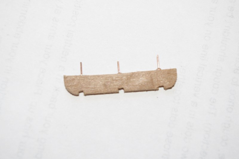
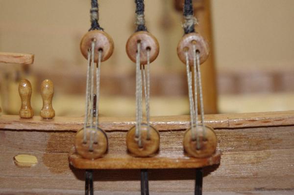
I also attached the deadeye channels and a pedestal for the backstay lower block. These are a variation from the instructions and are not shown in them. I made them from 1.5mm x 5mm walnut strip, once the lower deadeyes were fitted I fitted a piece of 2mm x 1 mm walnut strip over them and sanded it to shape. I left fitting the lower deadeyes until after the mast was fitted so I made sure they lined up correctly with the mast and so I could get the angle of the chains in relation to the shrouds. Unfortunately I cant seem to find any photos of the lower deadeyes fitted before they were rigged, I either did not take any or they were accidently deleted from the camera The pedestals were shaped and an eye pin inserted into them and then bent into a hook to take the dogbone plate that will be nailed to the gunwale later.


-
Hi Brian and Jason , Thank you both for your kind comments. I fitted the bowsprit next and wrapped the gammoning around the stem post and headstock. I then fitted the handrails these were also made from the supplied flexible beech


-
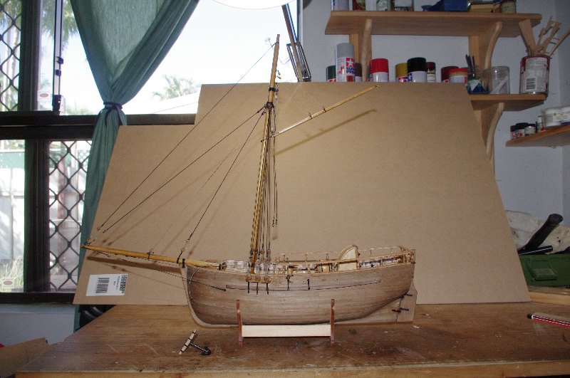
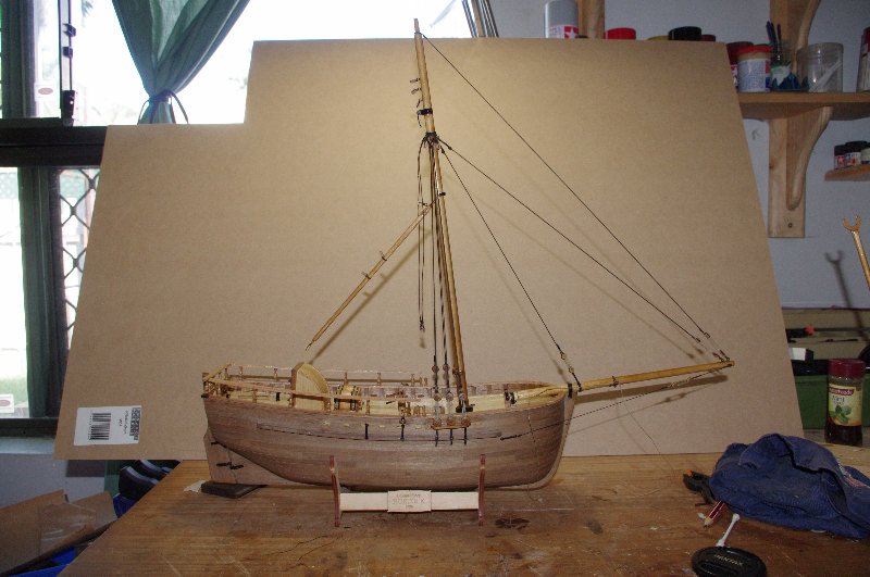
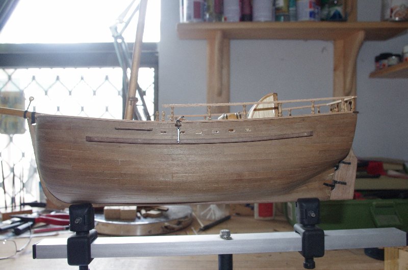
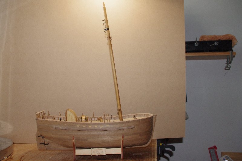
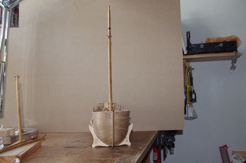
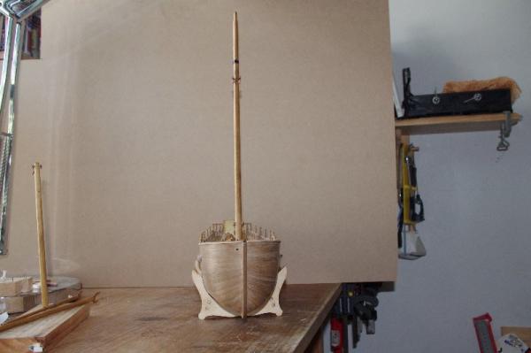
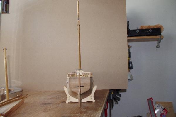
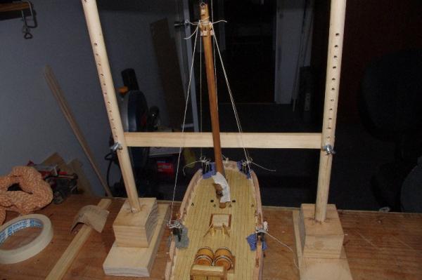
The next photo shows the mast heel fitted after the jig has been removed and also the binnacle fitted near the companionway. Some more photos of the mast, the first one shows that the mast has a severe rake, but I think it has a bit to do with camera angle and maybe the way it is sitting inthe cradle, it does not look that bad in real life.


-
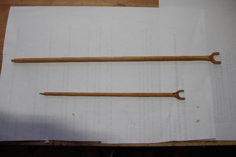
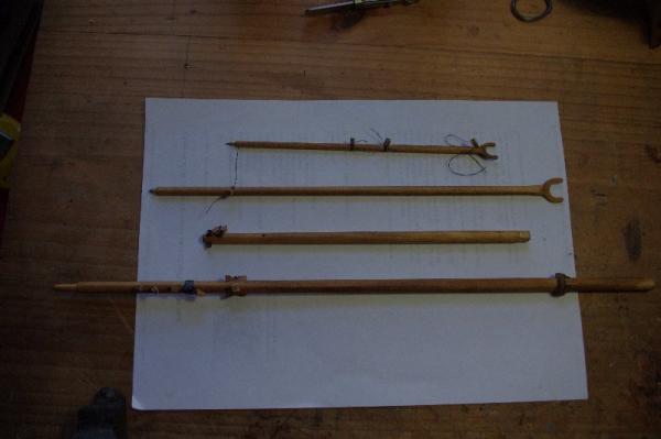
I also made the bowsprit and the gaff an driver boom while making the mast, these were also stained with baltic pine and any blocks required were attached.

- 98 replies
-
- 1
-
-
- norfolk
- modellers shipyard
- (and 1 more)
-
Yes Danny you are right it does look a lot more than 3 degrees in that photo it is probably a bit to do with camera angle ,but looking at the model again closely now I do think I have set the mast at more than the specified amount
-
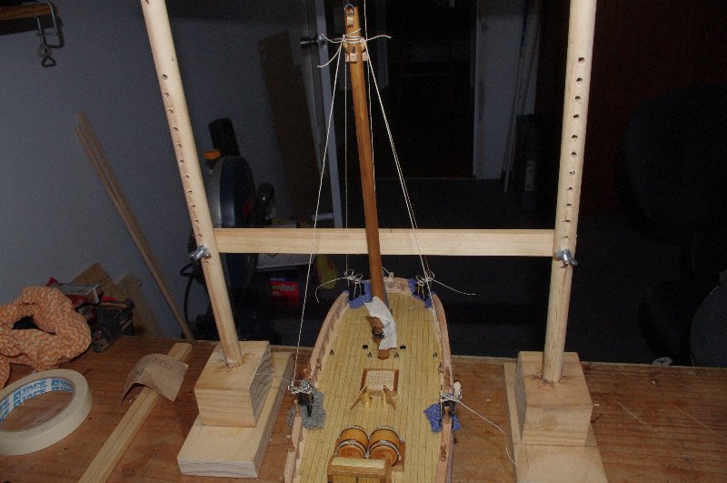
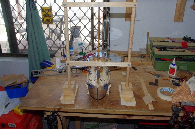
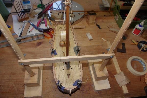
Hi All, My next job was to step the mast. I fitted it with the aid of a mast stepping jig I made from instructions from Frank Mastini's book 'Ship Modelling Simplified'. This jig helped me to line up the mast so it was perpendicular athwart ships and had the correct rake which was 3 degrees towards the stern.

-
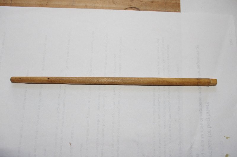
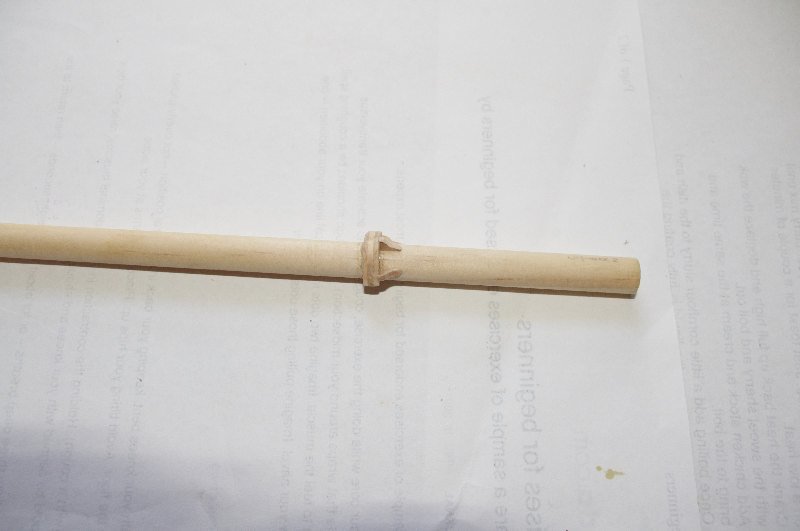
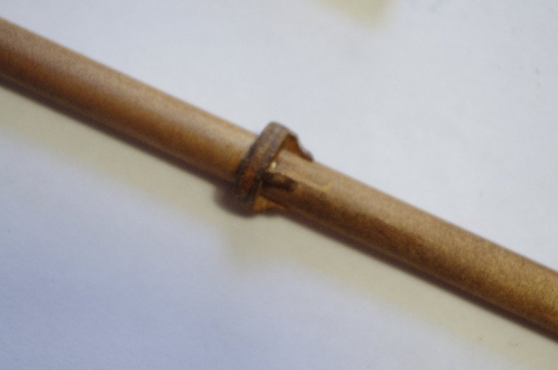
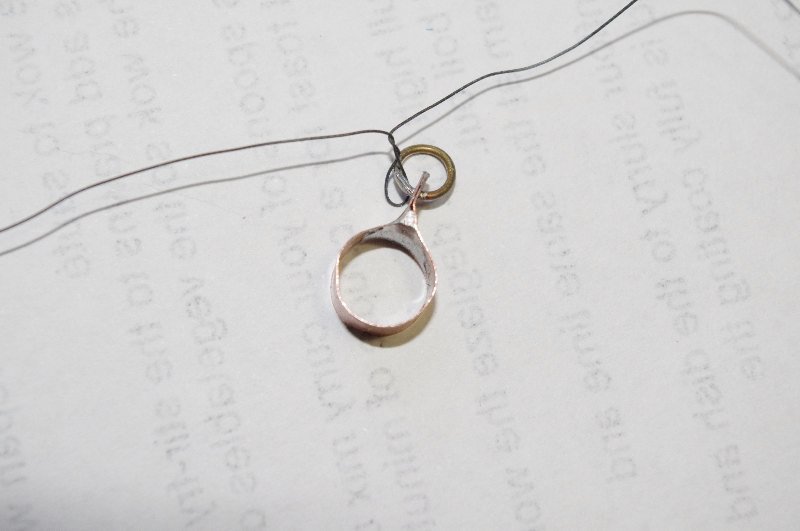
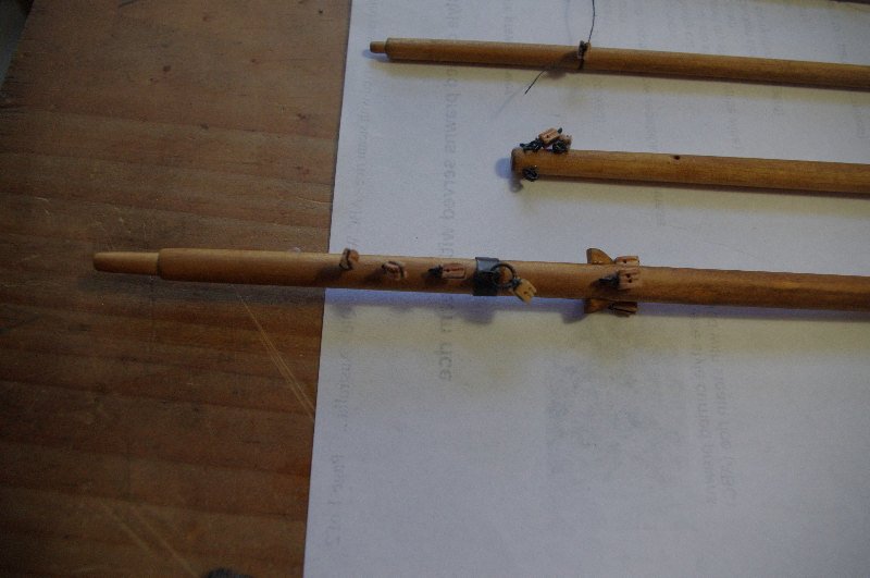
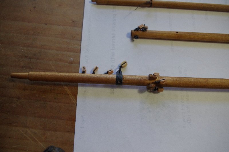
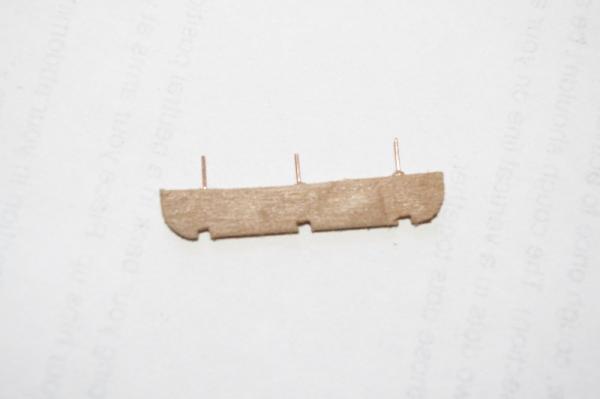
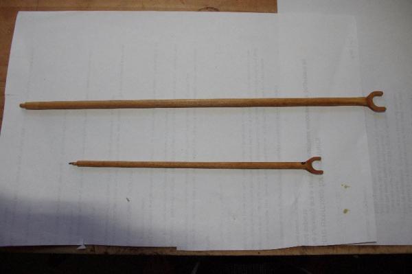
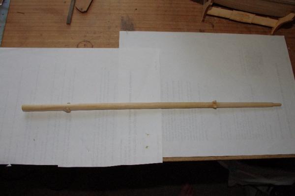
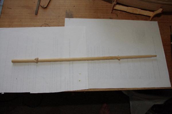
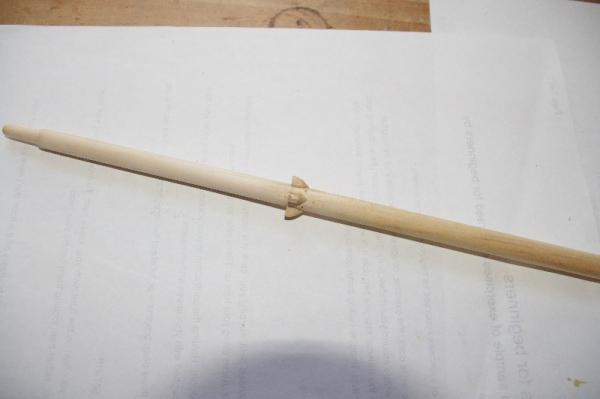
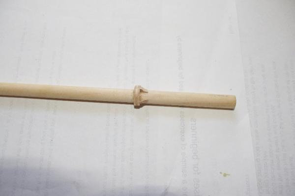
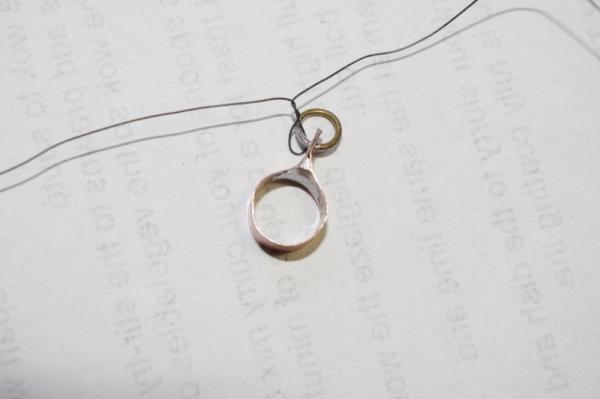
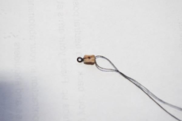
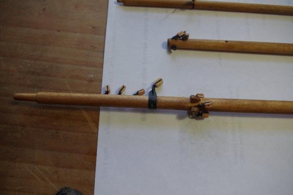
My next job was to make and fit the mast. Unfortunately when I went to start tapering the dowel supplied for the mast I found that it was warped and had a bad knot in the middle of it It pays to really check the contents of the kit properly when first purchased as I probably could have got a replacement. This was not the only problem as I was to find out later that I was also short a couple of dead eyes and rigging blocks , my fault for not checking the contents thoroughly when I first brought it Any way It was off to the local hardware store to find a new mast, the mast dowel size was 10mm which I thought would be readily available, wrong! would you believe it they make 6mm, 8mm, 9mm & 12mm dowel, no 10mm, so after searching through about 20 pieces of the 9mm dowel I came across a piece that was about 9.5mm in diameter, straight and no knots this became the mast. The rigging blocks after bieng shaped were stropped with 2 wraps of black cotton, any that needed a becket I dirlled a small hloe into the base of ther block and glued in a a small copper eye pin painted black and then stropped trough the ring for extra security. The mast was tapered accoring to the instructions and then holes were drilled to take the eyepins to hold the rigging blocks, the shroud cleats were fitted as was the boom support I also made the strap that is to be fitted 85mm from the top of the mast to hold the block for the throat halyard. The mast was then stained with Baltic Pine before the blocks were attached. Some pic's


- 98 replies
-
- 1
-
-
- norfolk
- modellers shipyard
- (and 1 more)
-
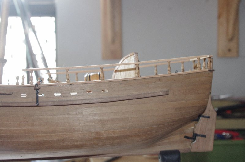
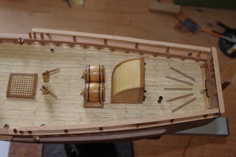
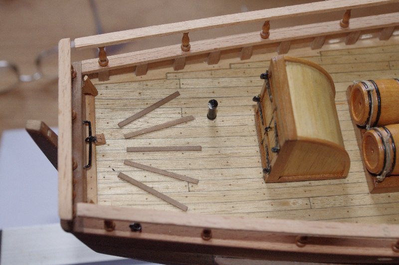
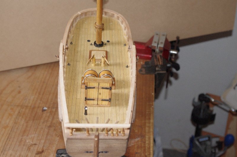
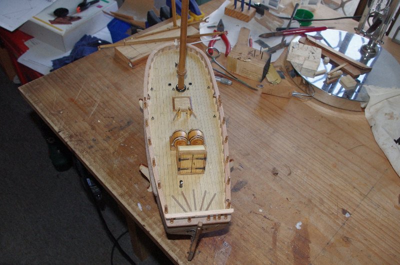
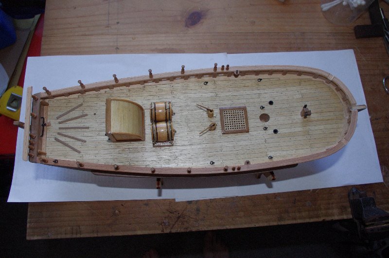
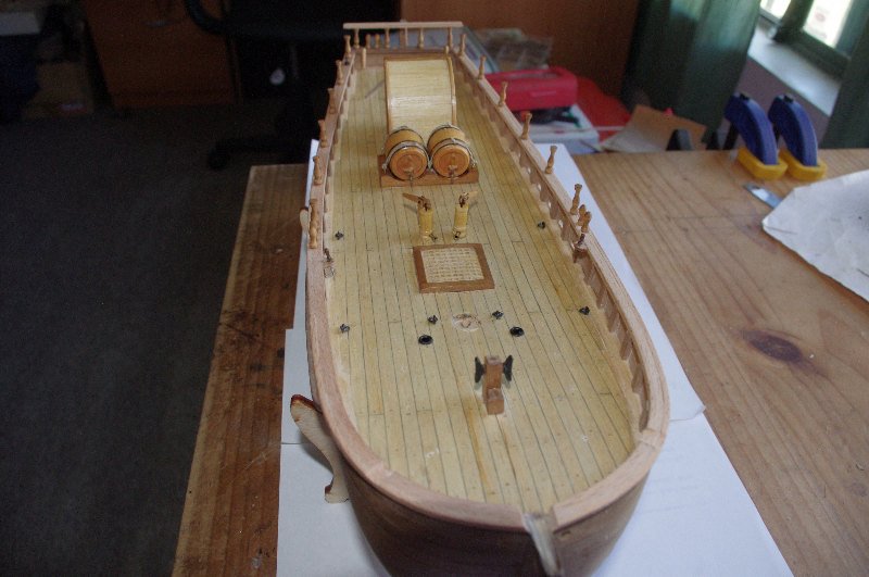
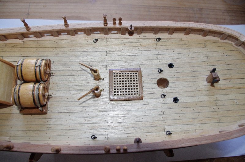
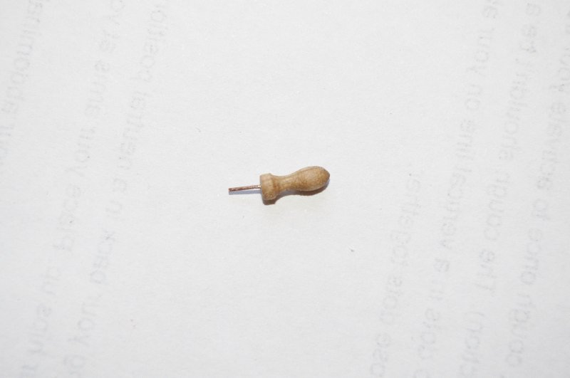
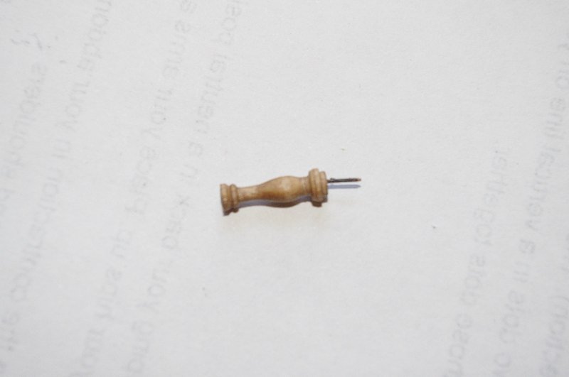
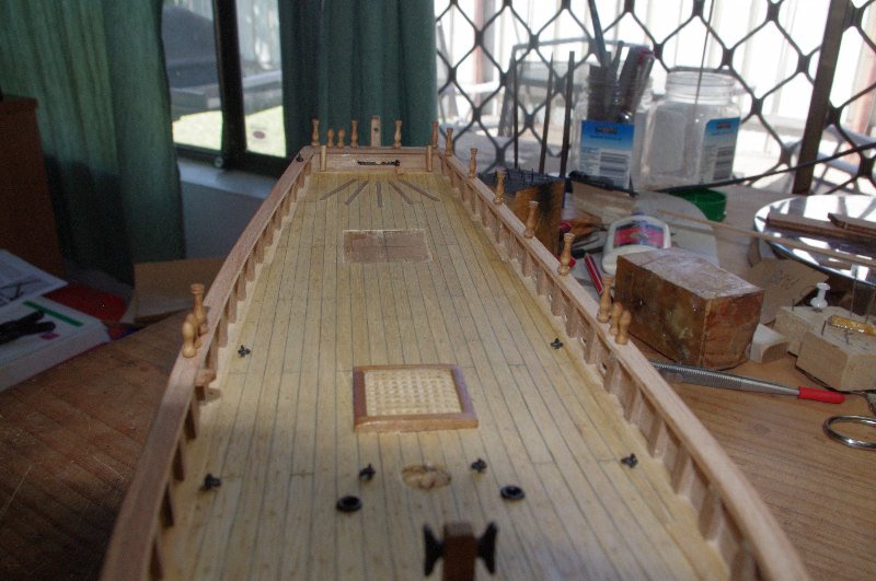
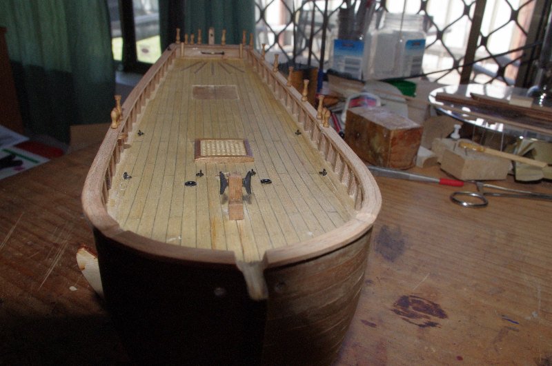
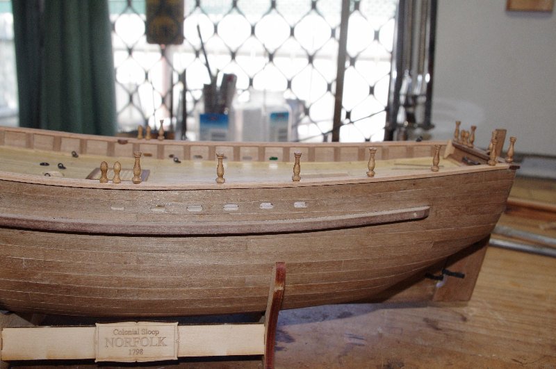
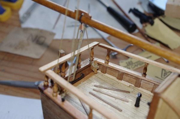
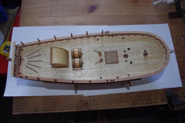
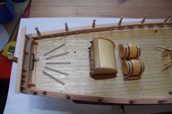
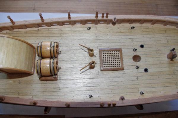
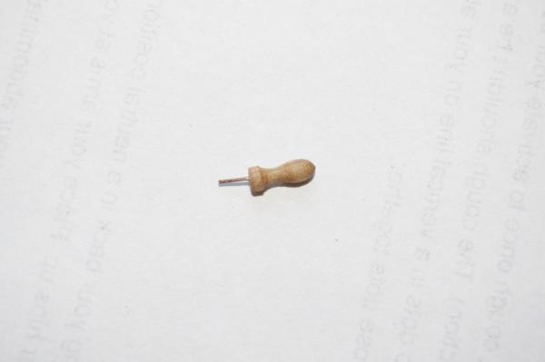
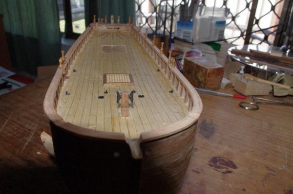
Hello All, After fitting the hand rail stanchions I glued on the compaionway, barrels and pumps.Also you can see around amid ships I have fitted 2 belaying pins in their own little rack. These are for the throat halyard and the topping lift to be belayed to later. The instructions tell you to fit the belaying pins straight into the cap rail and the pins supplied were too small. Some pictures of the fitted deck furniture


- 98 replies
-
- 1
-
-
- norfolk
- modellers shipyard
- (and 1 more)
-
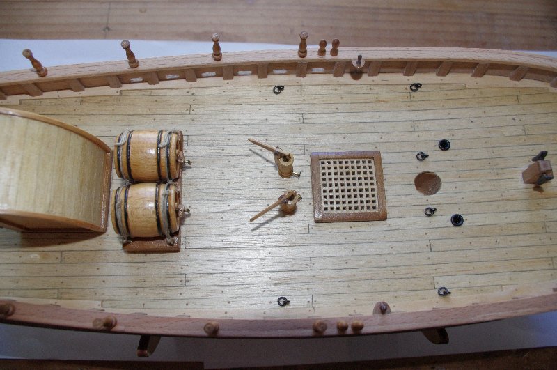
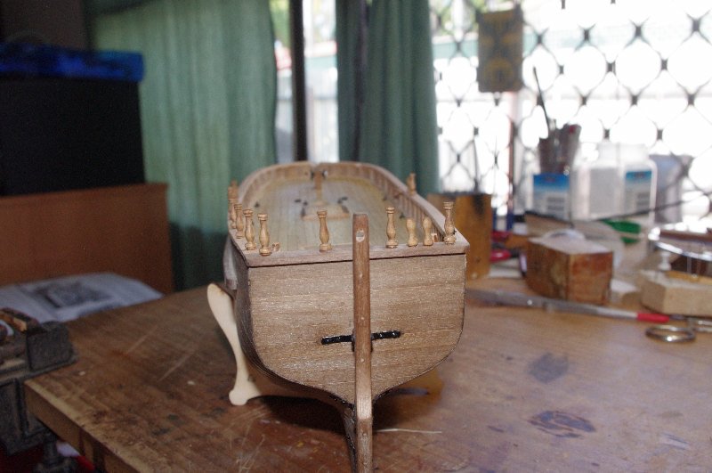
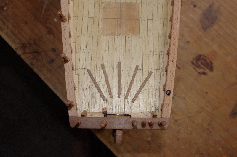
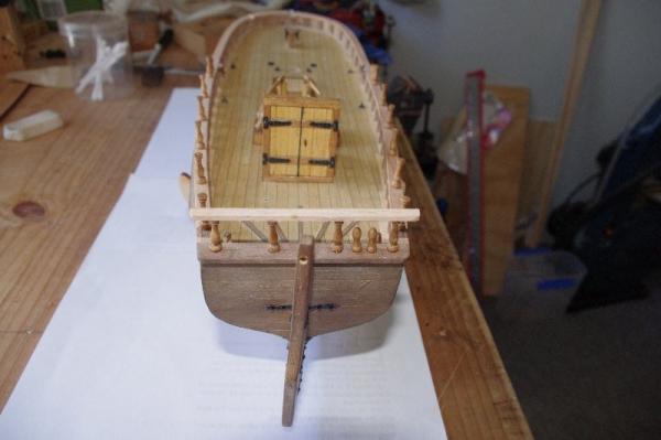
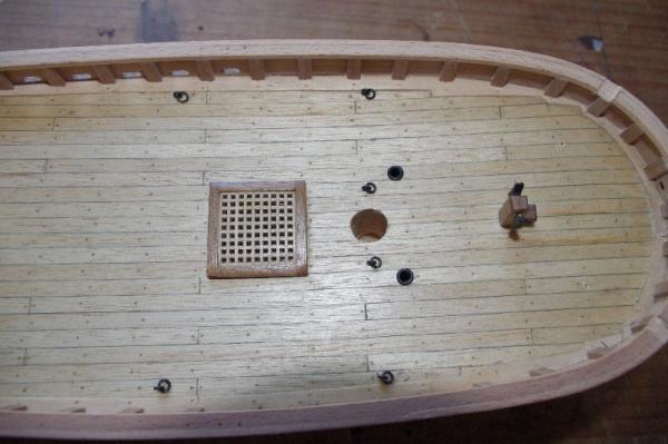
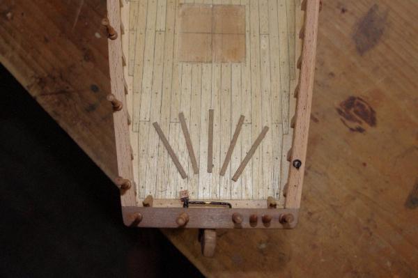
I fitted the hatch grating to the deck next and then I drilled a hole in each of the hand rail stanchions and rowlocks and inserted a brass pin into them for security. I then marked and drilled holes in the cap rail to accept them. As you can see on the last picture I have fitted the 2 cleats and the lower boom sheet block to the transom Thats all for now I will post some more pic's tomorrow


- 98 replies
-
- 1
-
-
- norfolk
- modellers shipyard
- (and 1 more)
-
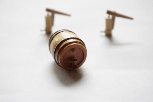
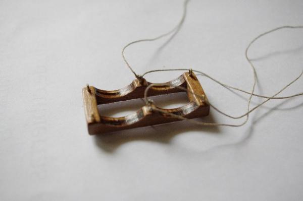
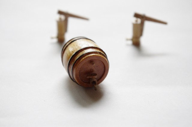
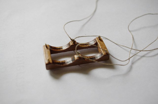
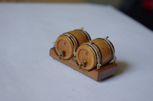
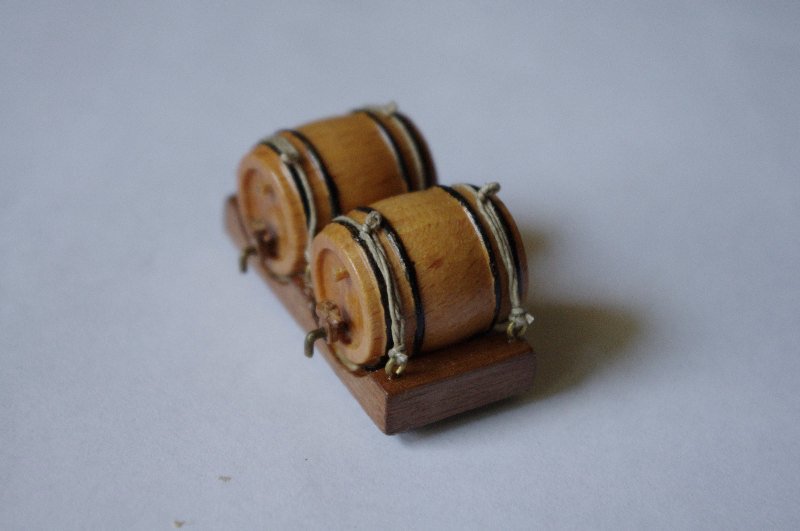
This series of pic's shows the construction of the barrel stand. It is made of 4mm laser cut ply which I covered with 0.5mm walnut strips, the barrels provided are turned boxwood which I painted and varnished I also added the brass taps and wooden bungs.