HOLIDAY DONATION DRIVE - SUPPORT MSW - DO YOUR PART TO KEEP THIS GREAT FORUM GOING! (Only 24 donations so far out of 49,000 members - C'mon guys!)
×

Gaetan Bordeleau
-
Posts
1,307 -
Joined
-
Last visited
Content Type
Profiles
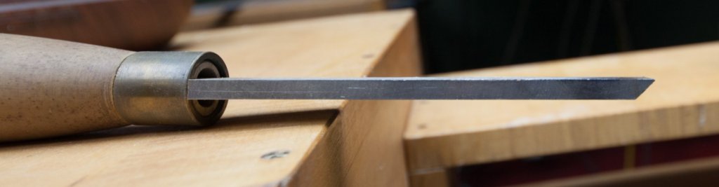
Forums
Gallery
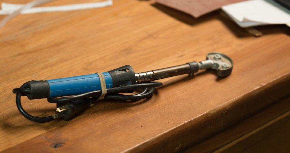
Events
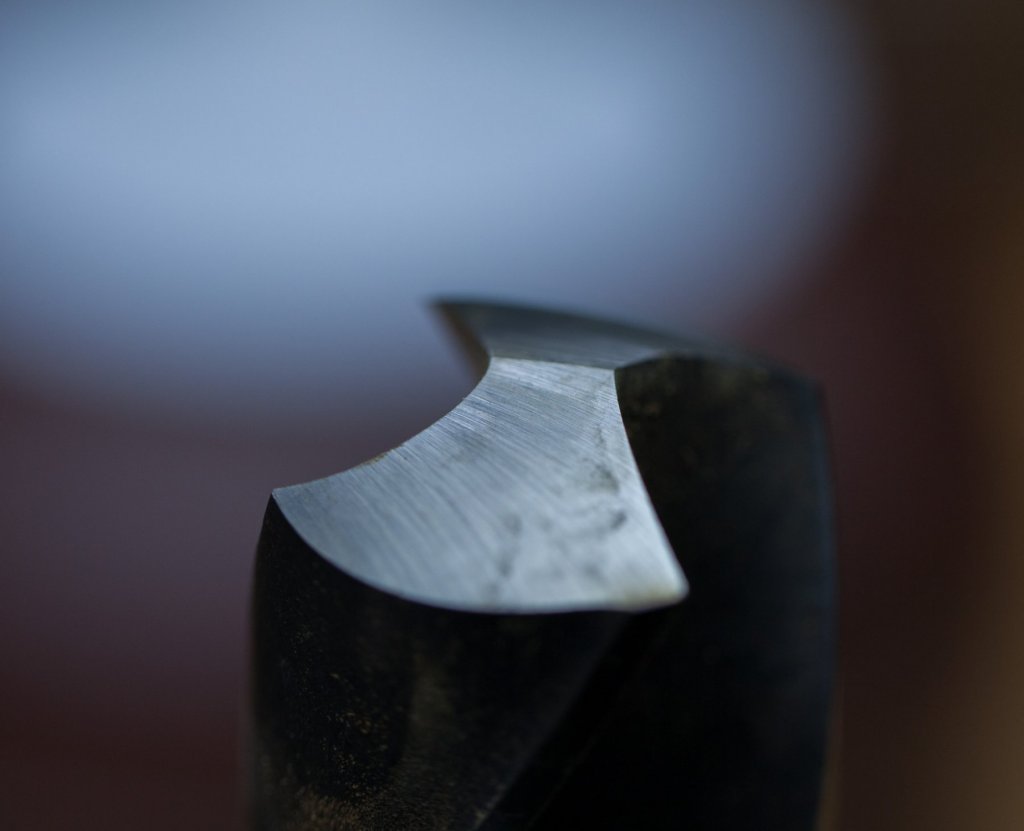
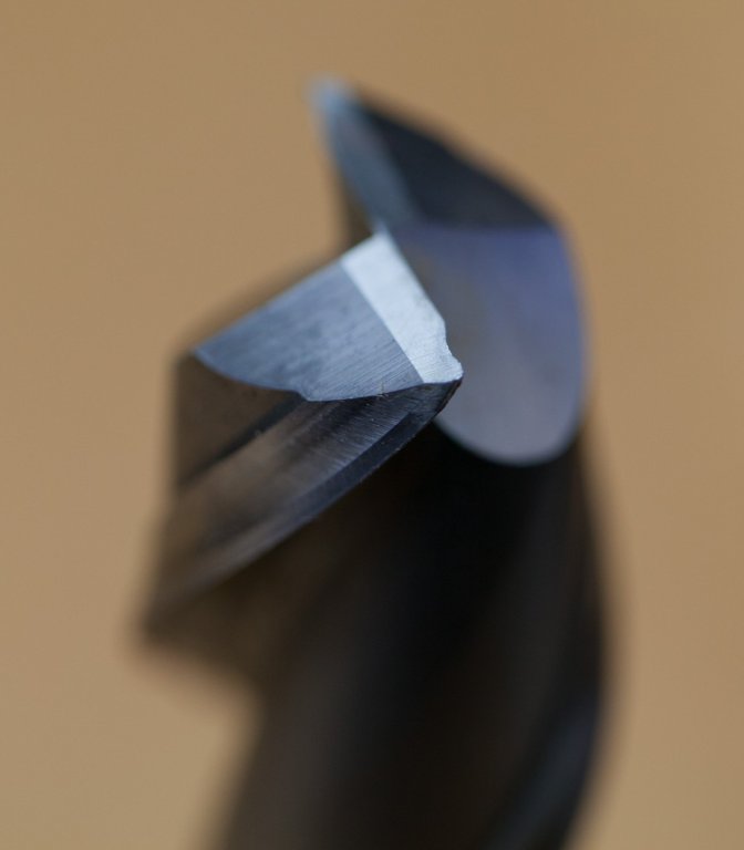
Everything posted by Gaetan Bordeleau
-
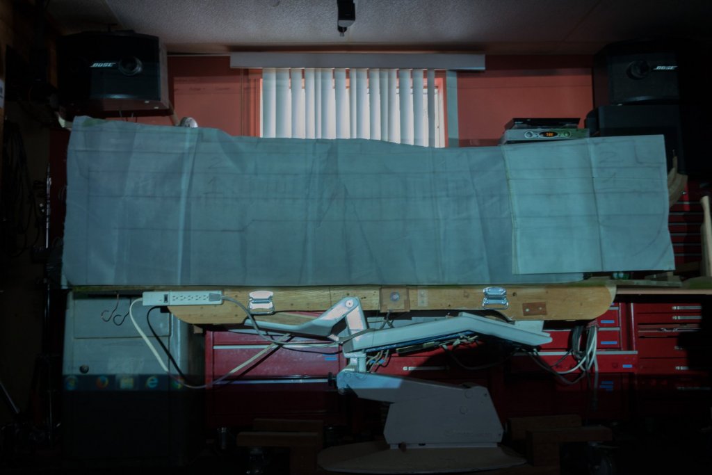
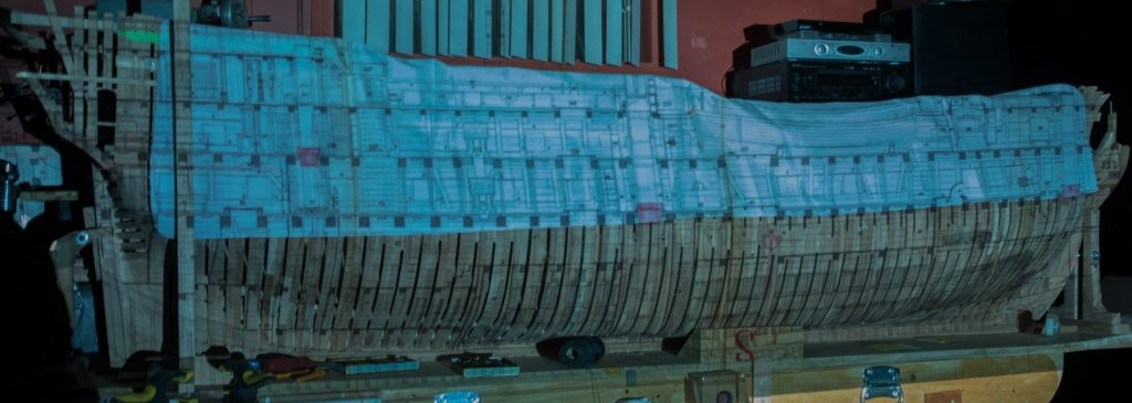
 Marc clearly explained why using a projector is useless. So the conclusion of this project is very easy now:
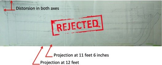
-
Hi Marc and Druxey and Carl I think you are all in the good direction!
-
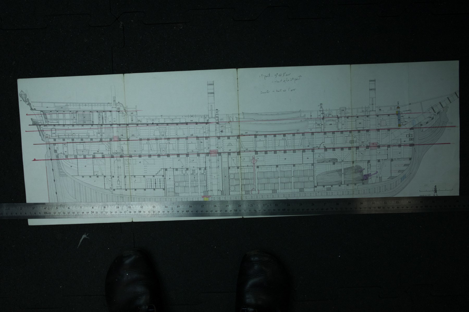
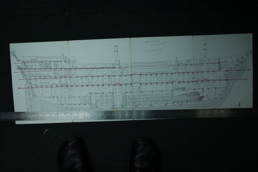
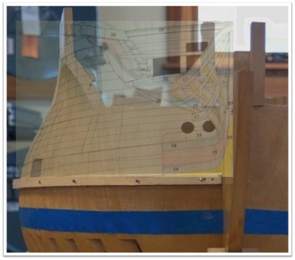
Carl, I surely will not give you an english lesson because it is not my primary language. You ask a good question and I do not really know the answer. At first sight, I would say that it is not possible. In fact, I do not think that it is what I do. Here is how I see it: It is like to transfer a 2D drawing on a 2D paper, the work is only in 2D. No measures are taken for the third dimension; depth. I remade the lines with more precision. Still have to check the lines. Height between decks is not the same for each one. In a house, usually all the height of ceilings are at the same height, but apparently not on the french 74. I traced in red, on the drawing, parallel lines to the keel at the lowest point of decks around at the middle. Overall, I would separate decks in 2 : fore and aft. The fore part are parallel to the keel. The aft part is much higher and in angle. I think that the engineers at that time were bright. I am imagining the next sentences, so I do not know if it make sense or not : Aft volume is smaller than the front half. When in water, aft part is deeper than the front one. I always thaught that it was because it was heavier but I do not really know why. May be because of the lest, may be because a bigger volume will float more! I have never tried it but I guess that if I put 1 ton of lest fore and 1 ton of lest aft, aft part would be deeper because of the volume effect. But anyway, aft part being shifted deeper and fore half being shifted higher, the height difference on decks become more equal fore and aft. Where there was almost no height difference at the fore parts we now have more. Water from both ends now flows better towards each end, and this is the camber. We can see it on the last drawing; before and after. I also tried to see the optical effect of a curve line and a kinked one at the bow, but did not get good results. That is enough dreaming for today.

-
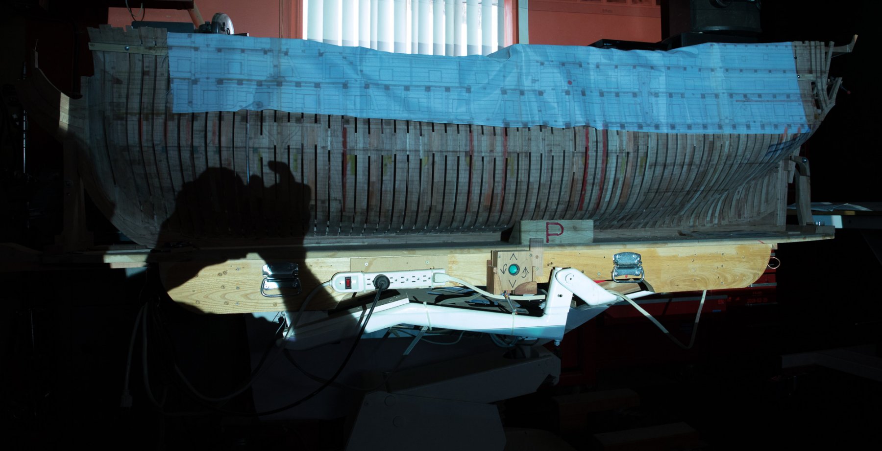
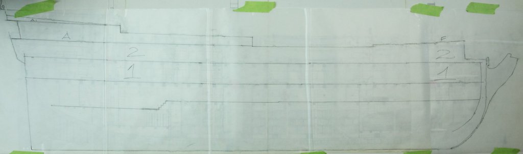
I traced fewer lines; outside shape and decks on a plastic sheet. Tried a fast transfer. Next step is to compare with transfer method of 1 coordinate at the time.

-
Hi Carl, Projection on a curved object : you will get distortion either in the vertical, OR, horizontal or both. Here is how I see it : The main problem is at the bow. If I look the curve of the bow from a top view, we see it in true lenght. If I look the curve at the bow from side, we see it shorter than what it is really. For this exercise, what is important is the view side : if the projection exactly fit on the model; lenghts are good and what is important here : the height of the curve is true and the goal here is to set points at the good height.
-
Hi Mark, Actually, I am trying to see if it is possible! If possible using this method would means less errors in lines transfer like wales, deck lines, gun port openings.
-
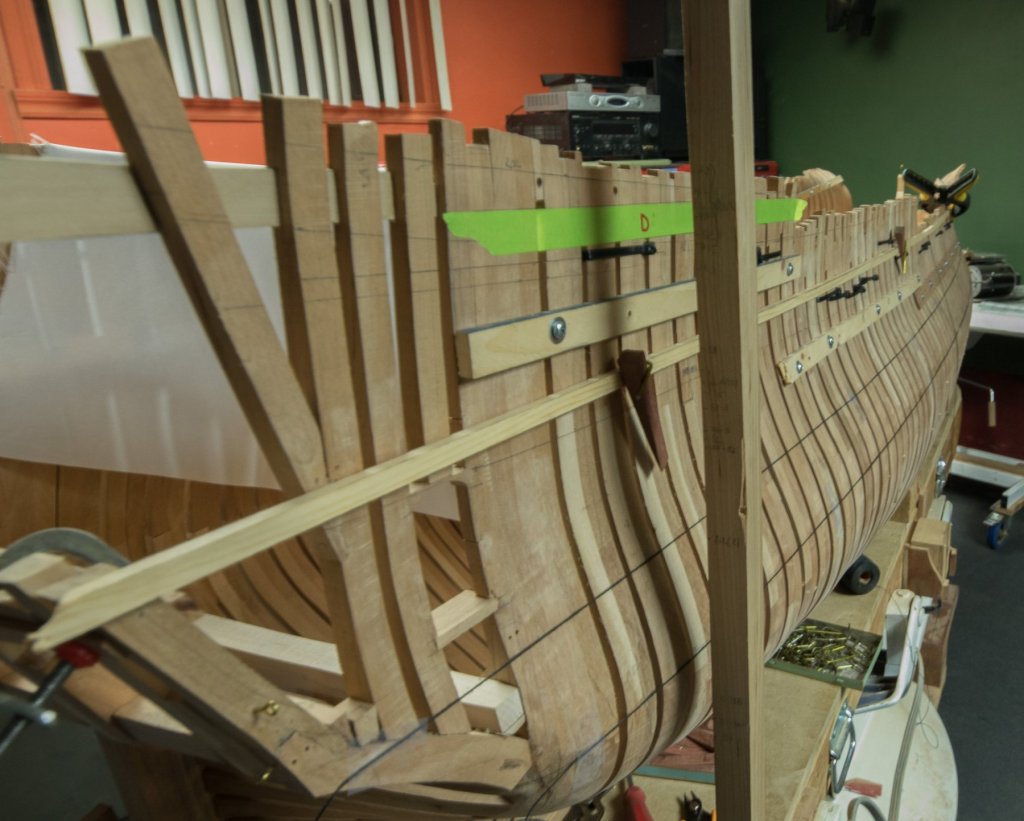
Not really working on the mode ship actually, just driving on the photography learning curve. Just doing some experiment in tracing. Simplified version to report a height on a stick. Marking with a black rope, it does easily follows the curves. I was too lazy to install a bigger vice for 1 hole only, I built a ‘’jaw extender ‘’. Actually doing some experiments with global markings using a projector. If I could use the image and do all the tracing, it surely would be faster.


-
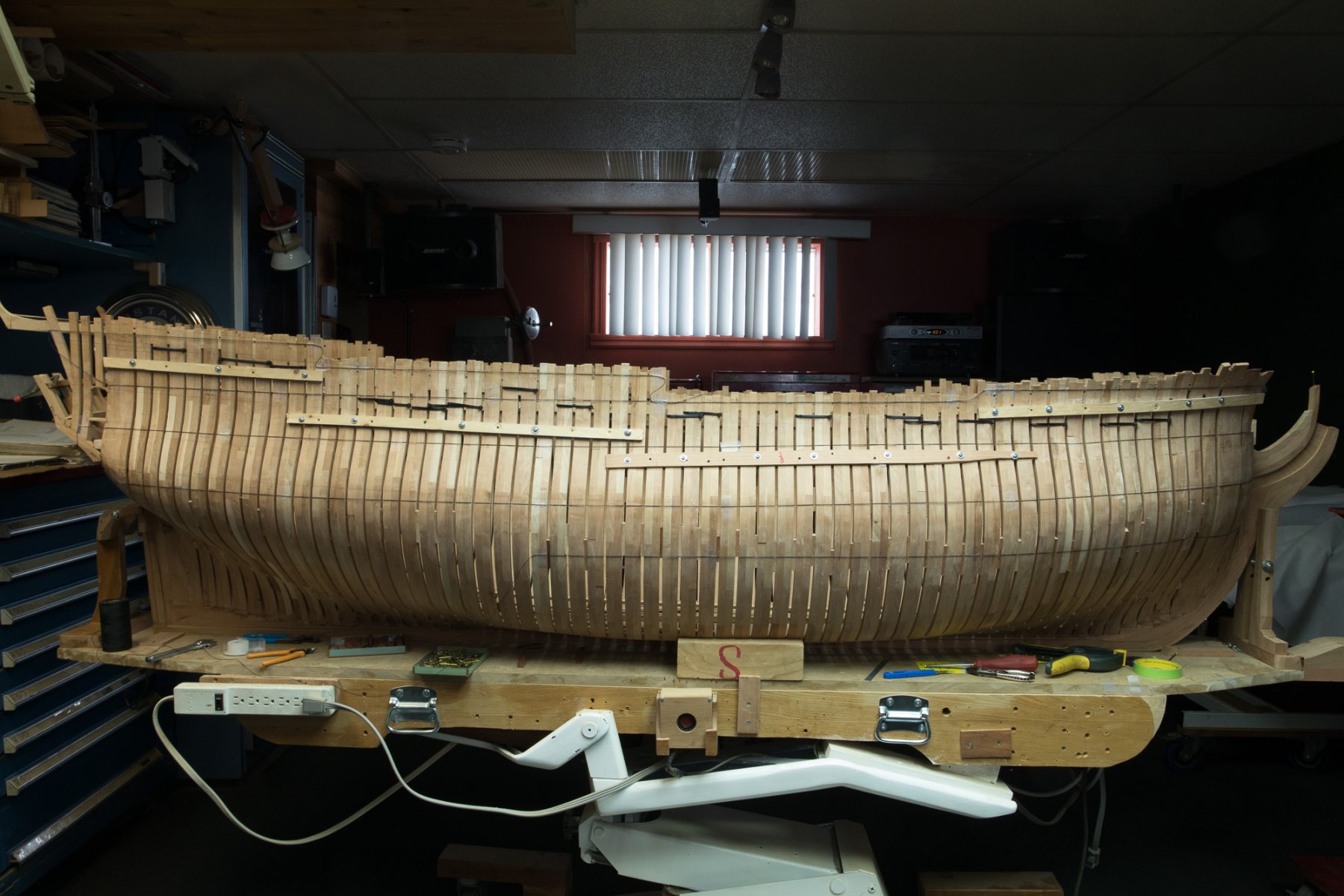
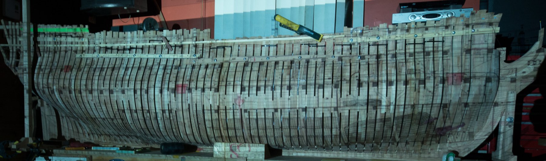
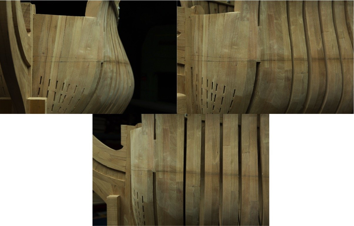
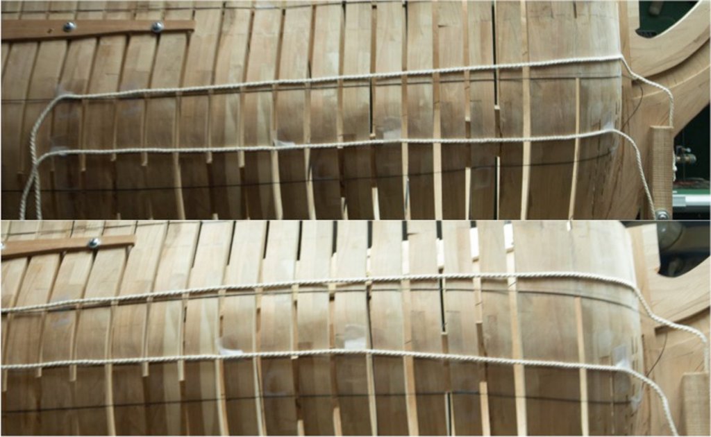
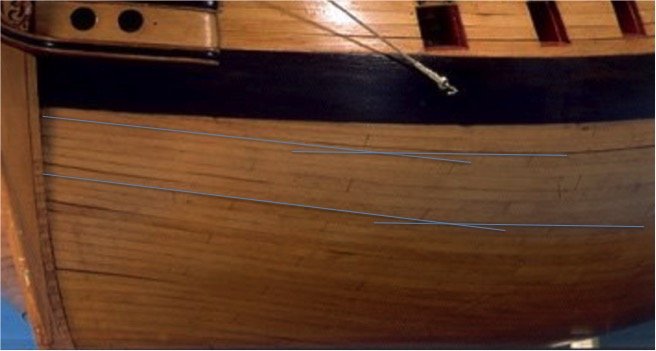
Mark I think your reference could be a bad reference because it is a partial planking. A fully planked model is a better reference. Here is what I think the modeler did with this model. He took the highway of the facility. He did represent 3 rows of a wale only. The 3 rows are made full width planks. If he would have continued his work without tapering extremities of the planks he would face some planks tapering to 0 and this we do not want for the simple reason that we cannot put a nail at the end of a plank finishing at 0 inch. Tapering the end of a plank means thatthe end of the next plank will come higher taking a part of the space of the upper plank. It is very difficult to start to the first plank at the good angle with the good curvature. It is also difficult to photograph the direction of the plank. Following your work, I returned to mine, observing that I did even worst. I think a good way to verify the regularity of the curve is to take 3 pictures : 1 front, 1 at 90 degrees of the middle of the strake and 1 side. I did repeat the process 3 times and corrected the end each time. The lower line was before, the upper is now which seems to look better. Still needs some adjustments but I think that if the results is smooth on the 3 photos, then the result can be good. Also I think that taking pictures after doing the work has the same result as usual, The camera has no pity of our work.

-
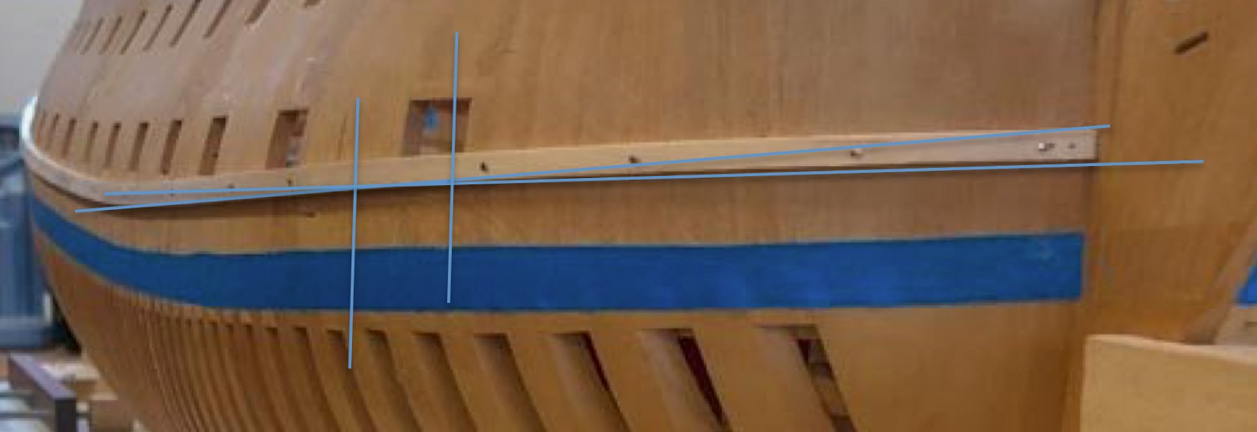
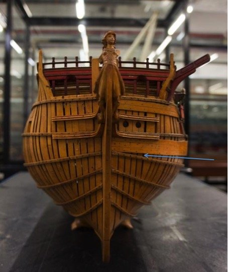
Hi Mark, I see why you went this way. My only concern how the planking will end at the blue arrow?
-
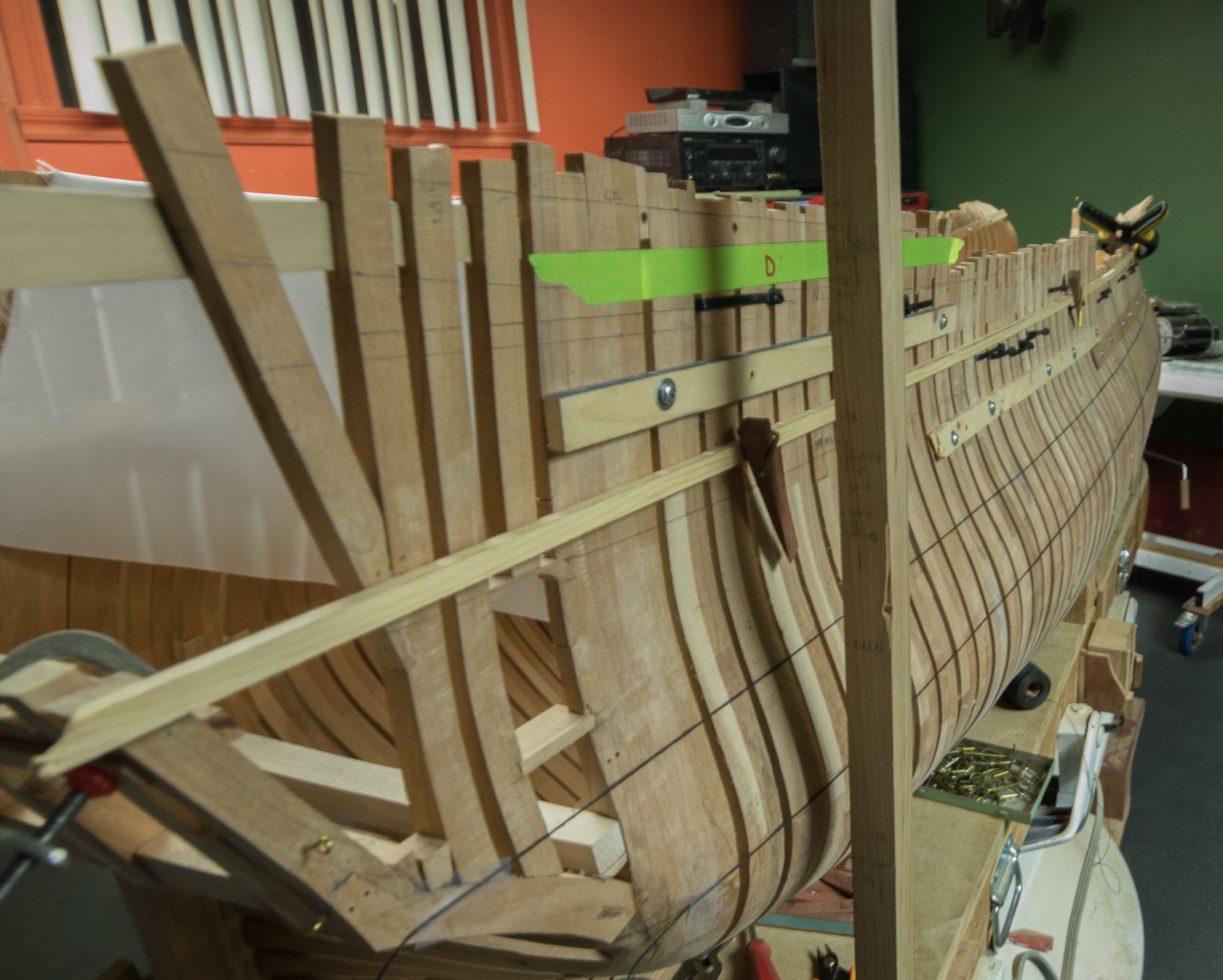
Recently I did trace this line on my french 74. and for the front part I used masking tape because the wood batten did not have enough flexibility. As a comparison, the french ship line is higher.
-
Mark, is it possible that I see 2 curves direction?

-
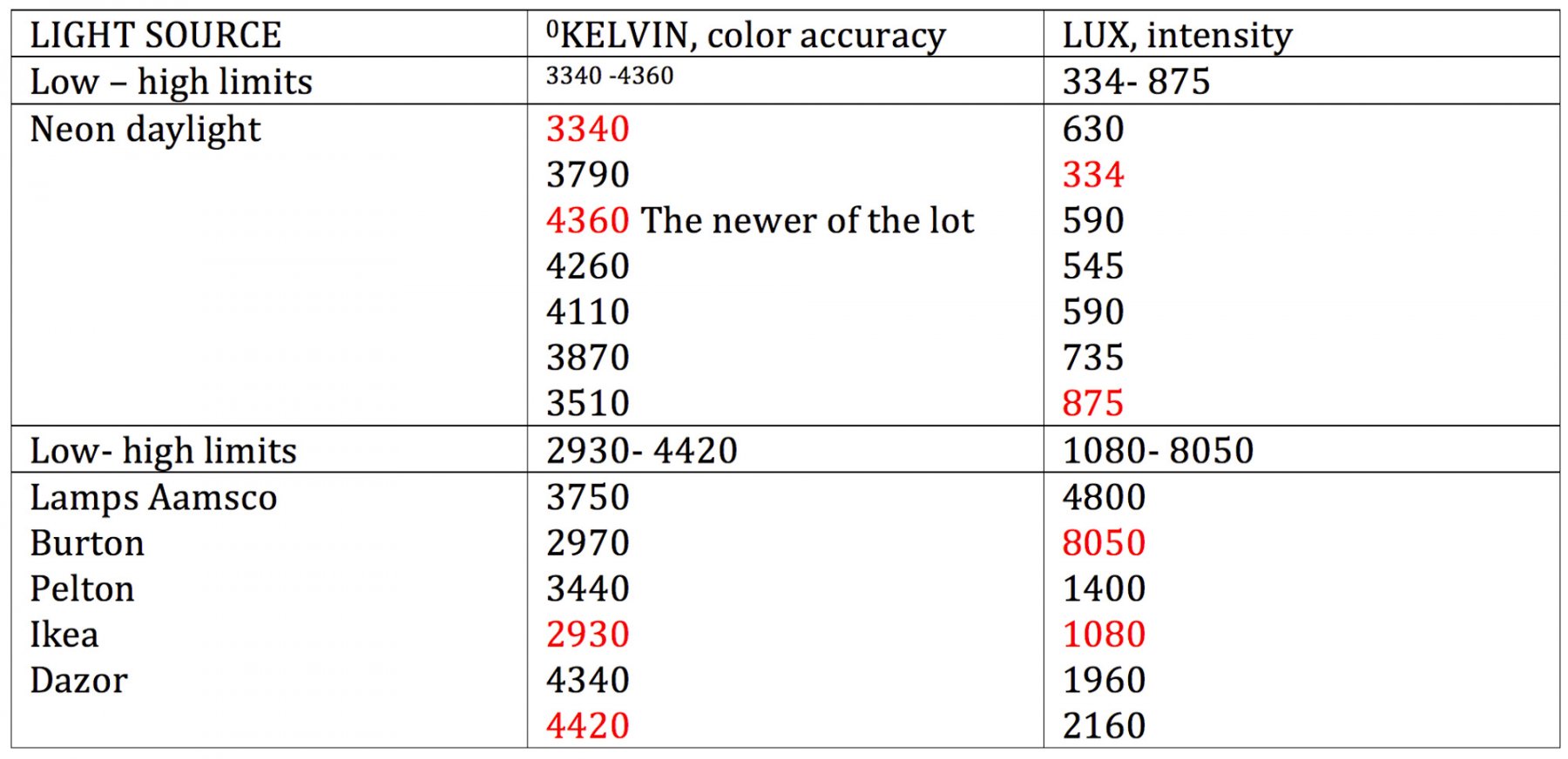
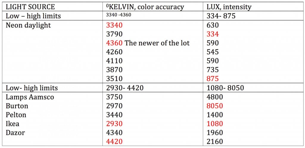
Than you, Mathematical properties of light have always interested me. Here is a little test I did this morning, just for fun: I measure the color accuracy and the intensity of neons and lamps in the workshop. My conclusion would be the following line: In home, if I really want to capture the true colors of a model ship boat, a flash reaching at least 5000 0K must be use. That was the hard way, now the easy way, just do it outside. -2 kinds of light source neons and lamps -Lux values closely related to the distance : the closer to the source, the stronger the value -Readings are stronger with lamps, distance is about the half of neon readings -Tests to be exact would need readings at the same distance, this is not the case here. - For a daylight of about 5300 0K, the closer I have is a Dazor lamp with neons -To reach 5000 0K, a standard daylight value, a flash must be use Possibly new LED lights have closer color to what we see during a normal sunny day.
-
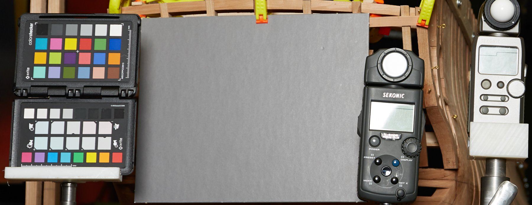
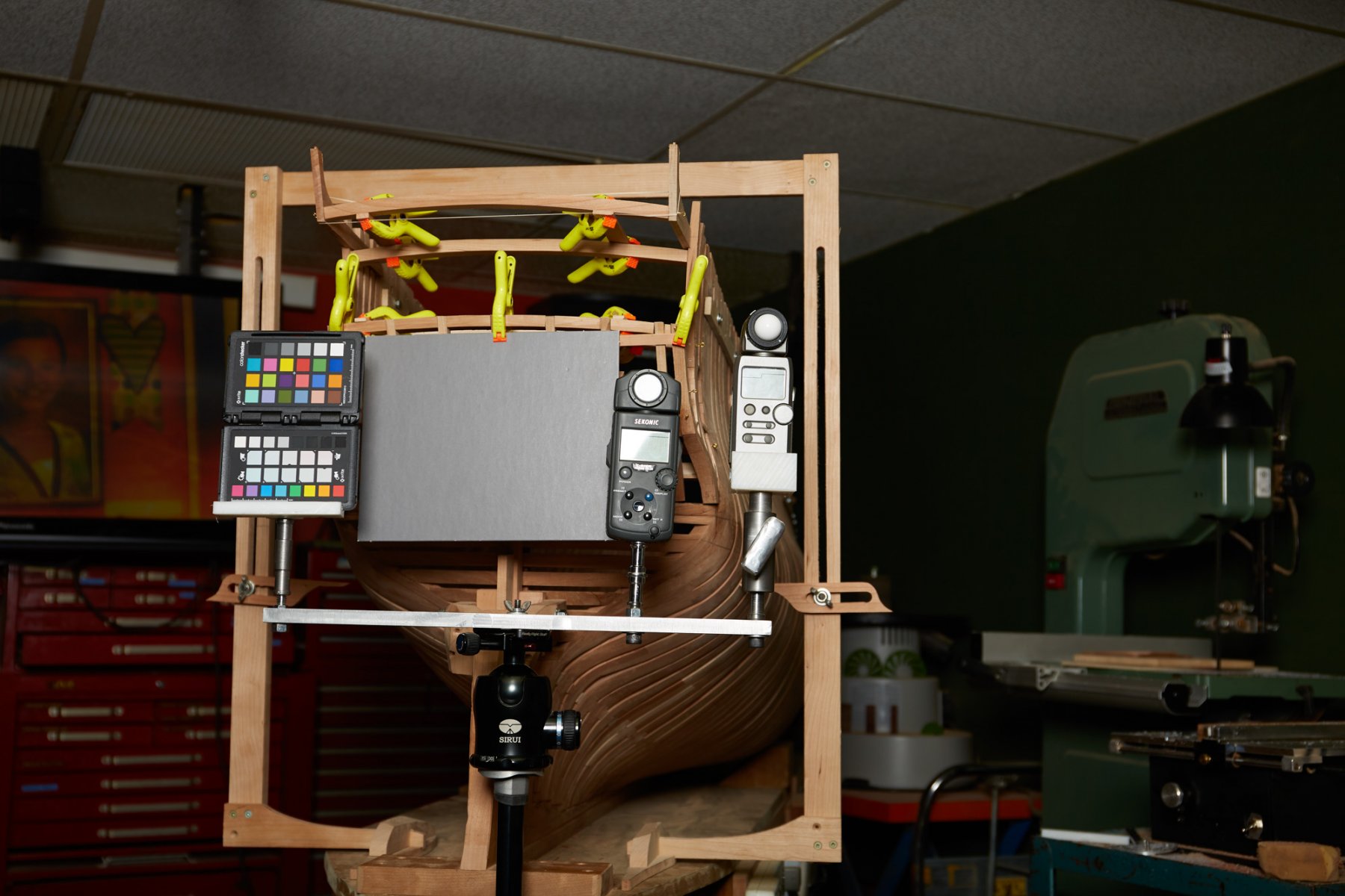
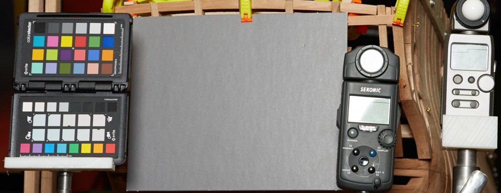
Hi Mark, Often white balance is adjusted after the photo was taken with a program to correct photos. White balance adjusts by comparison with known color values. From left to right: Color checker card grey card 18% These 2 are used after a photo was taken. Sekonic color meter and light meter are use before taking a photo. A camera is far from to be as smart as a human eye. Taking a photo with different kind of lights and intensity will give photo. Ideally, we want to take a photo with exactly the same colors. These things helps to come closer to the true colors. Sometime it is not important but sometimes it is. Color meter let us know how to adjust white balance before taking a photo, so there is no color correction needed after the photo was taken. To day it is easy to correct a photo after but when film rolls were used, we can easily understand that we can prefer to have the right colors because after, iy was too late. Light meter is use to tell us instantly what opening to use with a certain strength of a flash. If no light meter is use, we would have to guess which opening to use on the camera but it could take a certain time before to find it. I hope it is clearer Gaetan
-
The model ship not being over yet, it means that you still have plenty of time to modify things on the wall. You are in advance having a case already at this stage of building. Bravo!
- 968 replies
-
- 3
-

-
- hahn
- oliver cromwell
- (and 1 more)
-
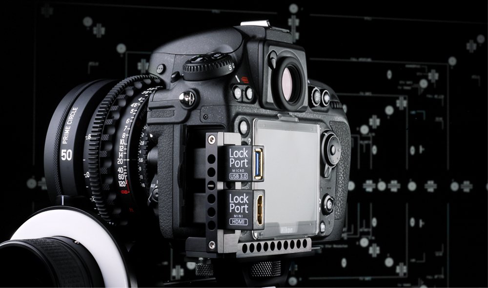
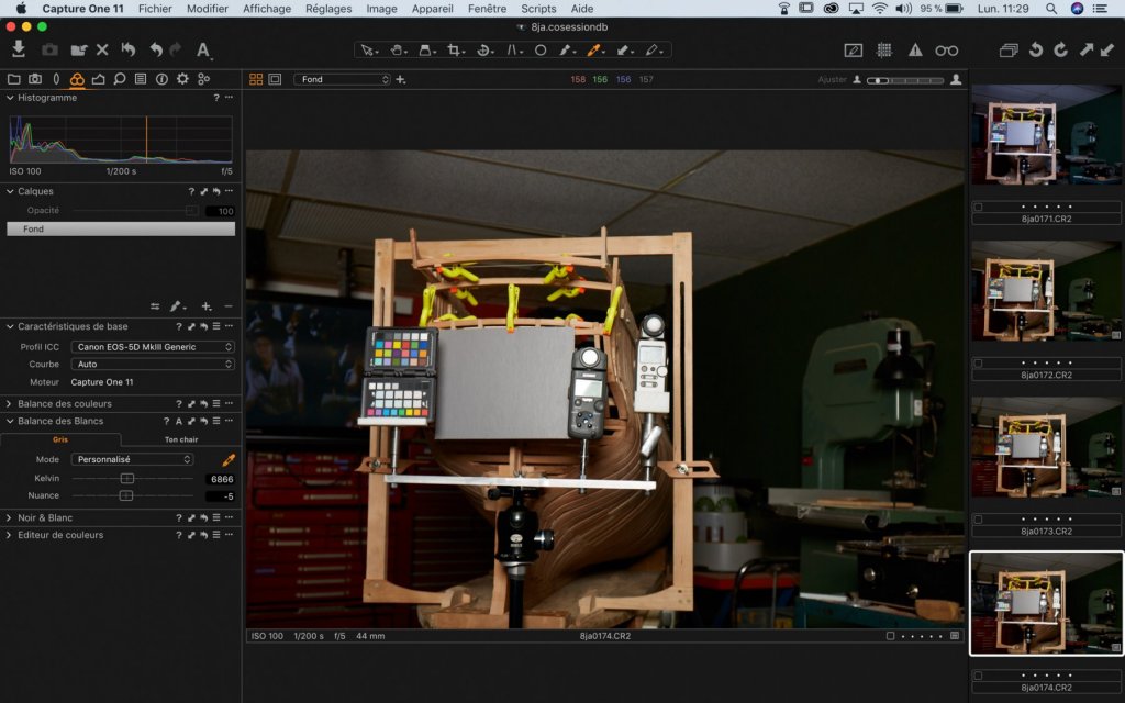
The first one is a wood square to hold 1 pointer each side of the model ship from. This jig can move from one end to the other. It is use to transfer a height value from 1 side to the other. 1 measure is set 1 side and the other one is set by using a parallel line given by horizontal line of a laser. The second jig is made of high density plastic. Many years ago when I began making tools, steel was always use, later to make the job easier fo the machines, aluminium was used. Today, when a small rigidity is needed, plastic is use. It is as easy as to cut in butter. Everything is easier to clean after the job and no liquid is needed for heat reduction to help and preserve the tool life. For this little cable holder, I took my inspiration from the third picture but made it a bit less complicated. This holder is made to help to preserve the quality of the mini HDMI camera connector which are very easily bent. The forth picture is a screen from a program use for photo sessions. Capture One requires a cable between the camera and the laptop but the transfer is very fast in comparison with Lightroom, no cable connector, wifi connection but a much longer transfer time (a small second in comparison to many seconds). When taking photos, White balance use by the camera is always approximative from auto to sun, to neon… WB can be the first parameter to adjust on the camera. For a long time, I wanted to get more precision with this parameter. At the end of last year, I got a meter to measure the quality of the color in Kelvin degrees. Then, choosing ISO and time on a light meter, aperture (F) is given to use with the flash intensity. Values are then transfered in the camera, photo is taken and transfered in the laptop program. Minor adjustments can be done if required. By adjusting WB right at the beginning of the process, post production of the image is much easier but there are still minor corrections for highlights and this kind of adjustments.


-
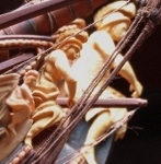
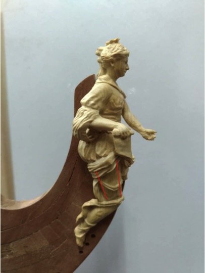
Hi Hjx, looking at the second picture: some more work inside the right hand may be left thigh, I do not if it is the angle of the picture but in comparison proportion of the right one looks better. head too big, I do not see that in proportion
-
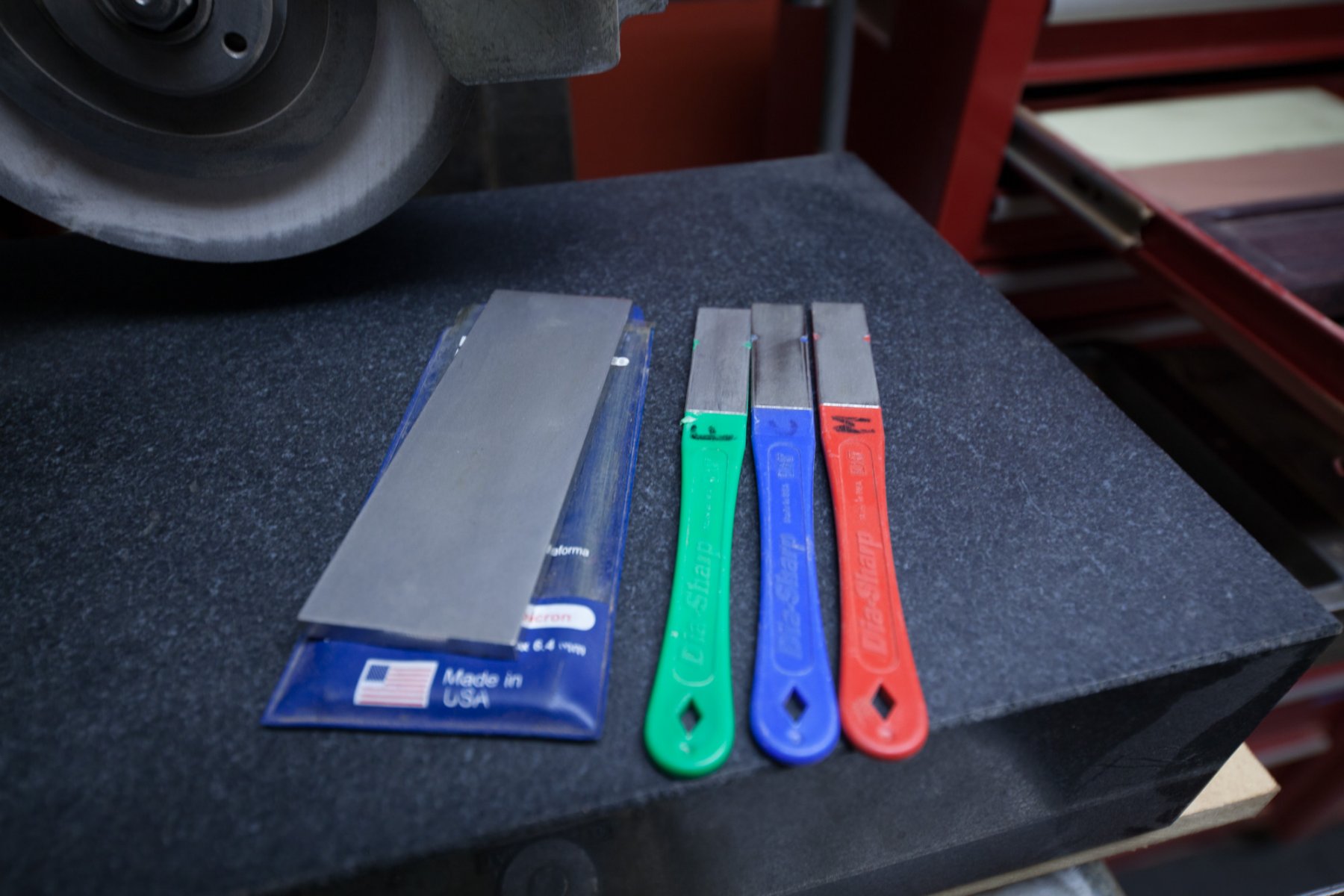
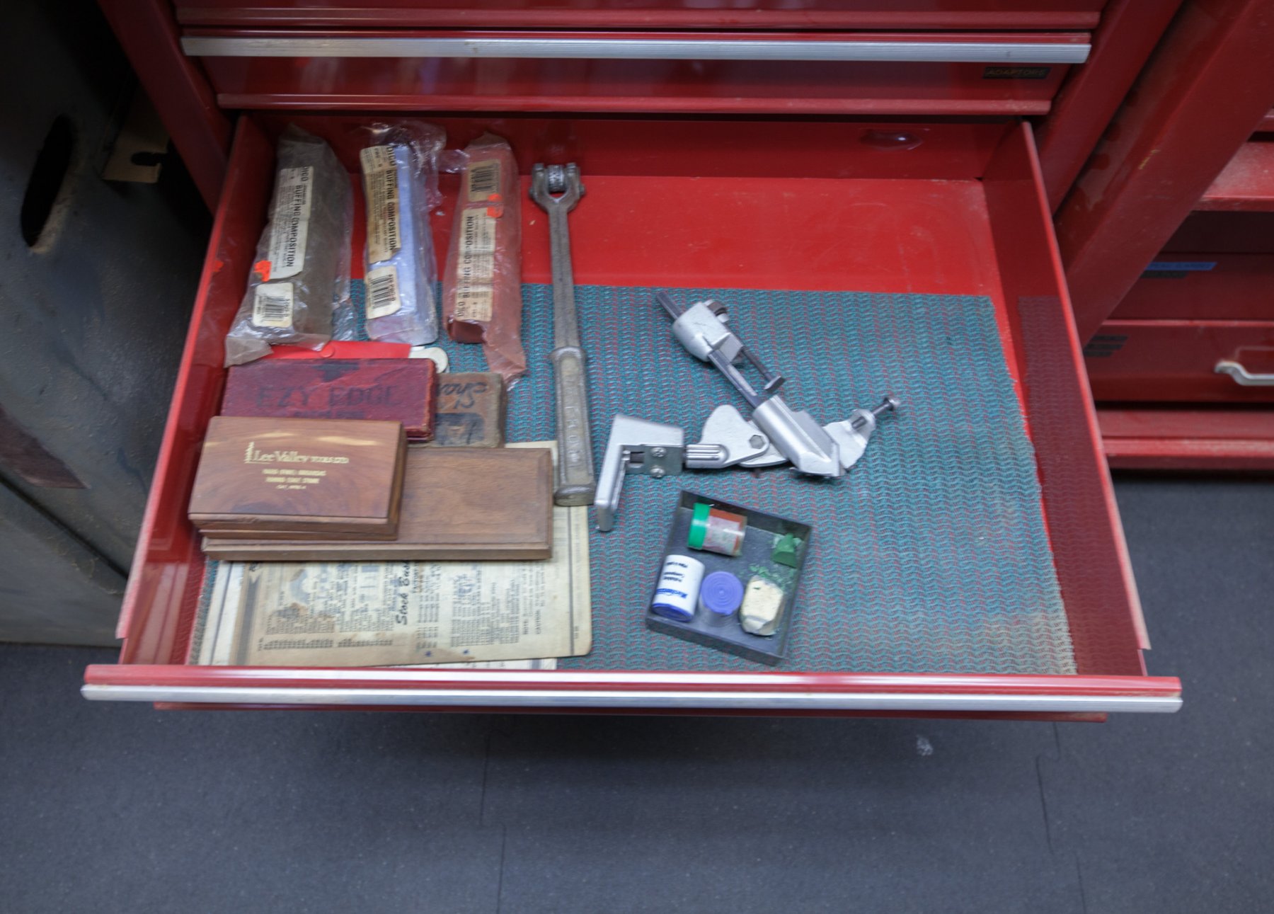
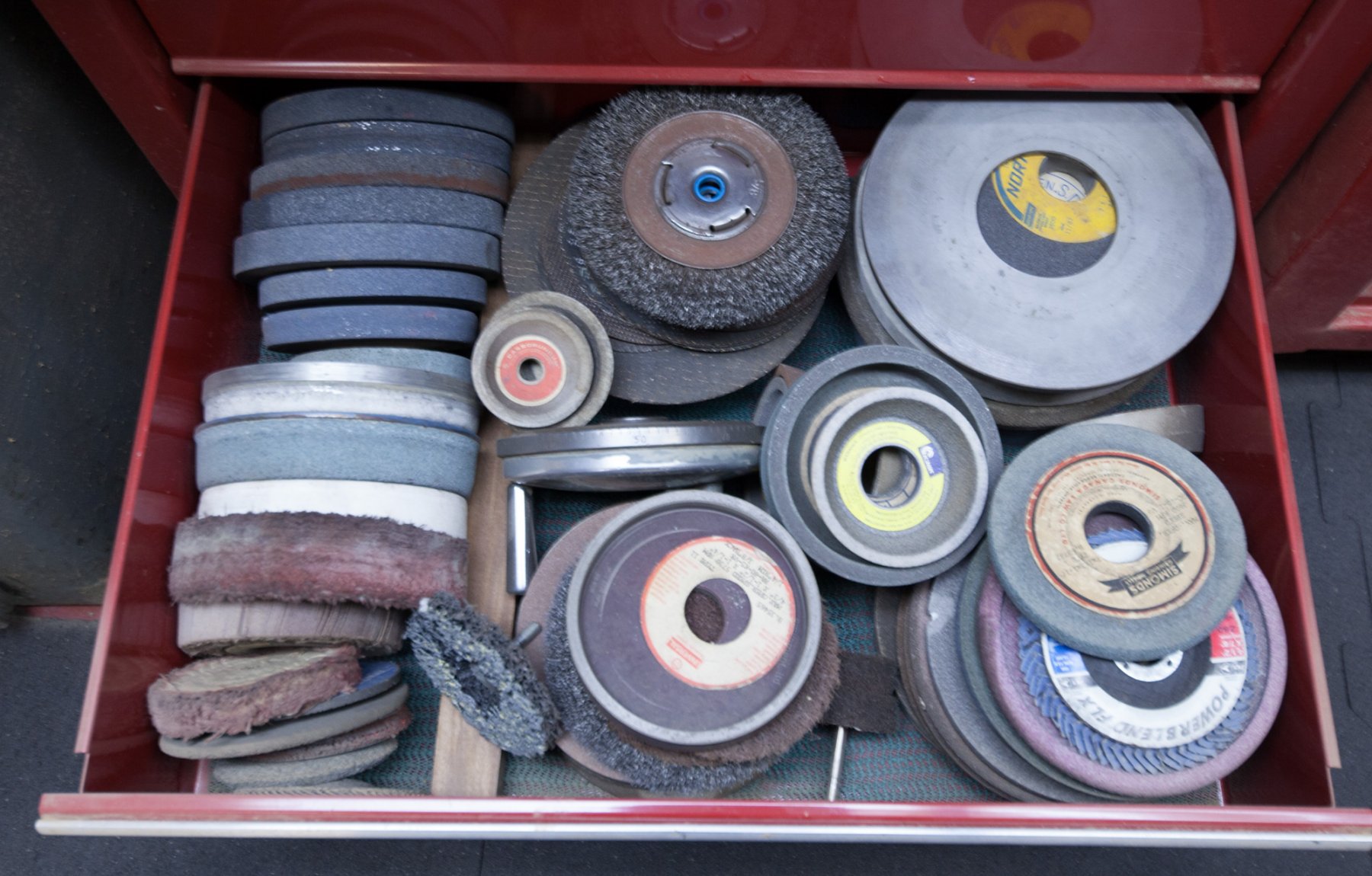
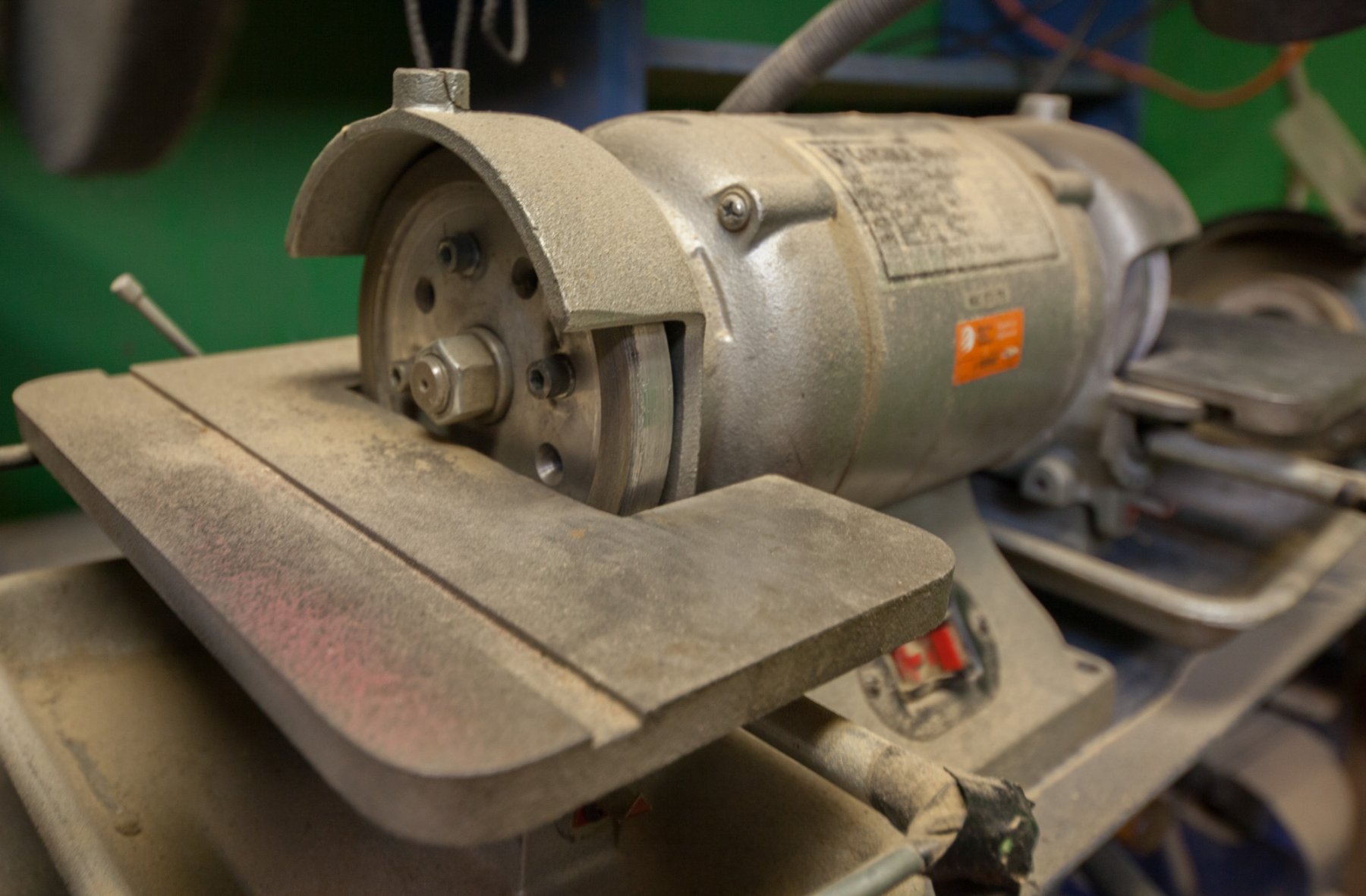
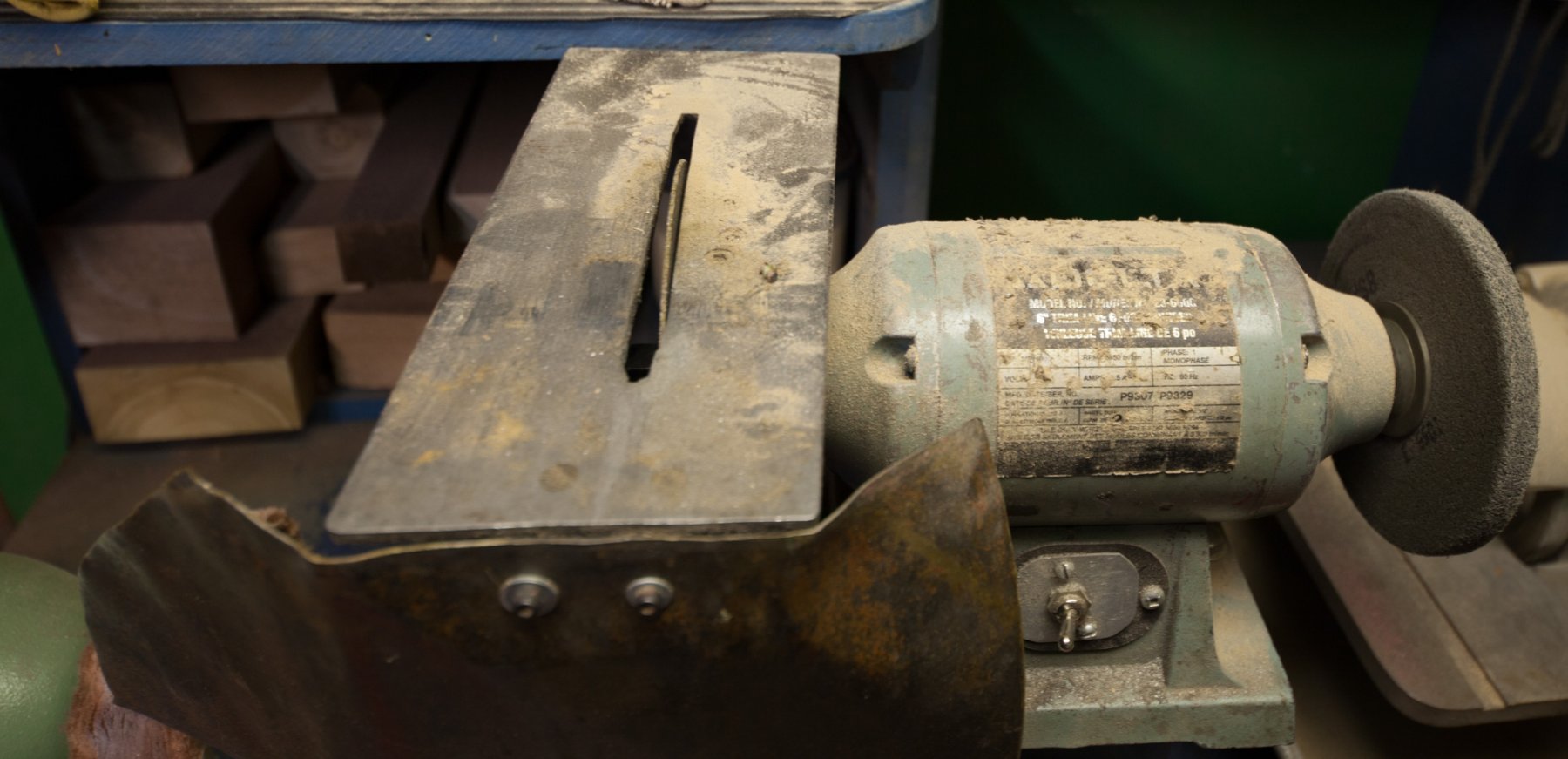
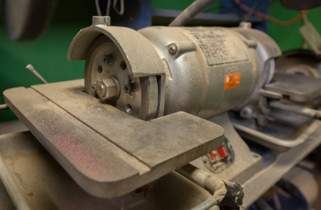
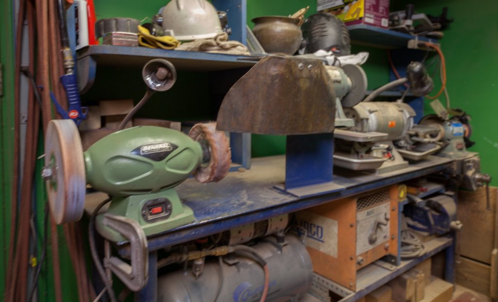
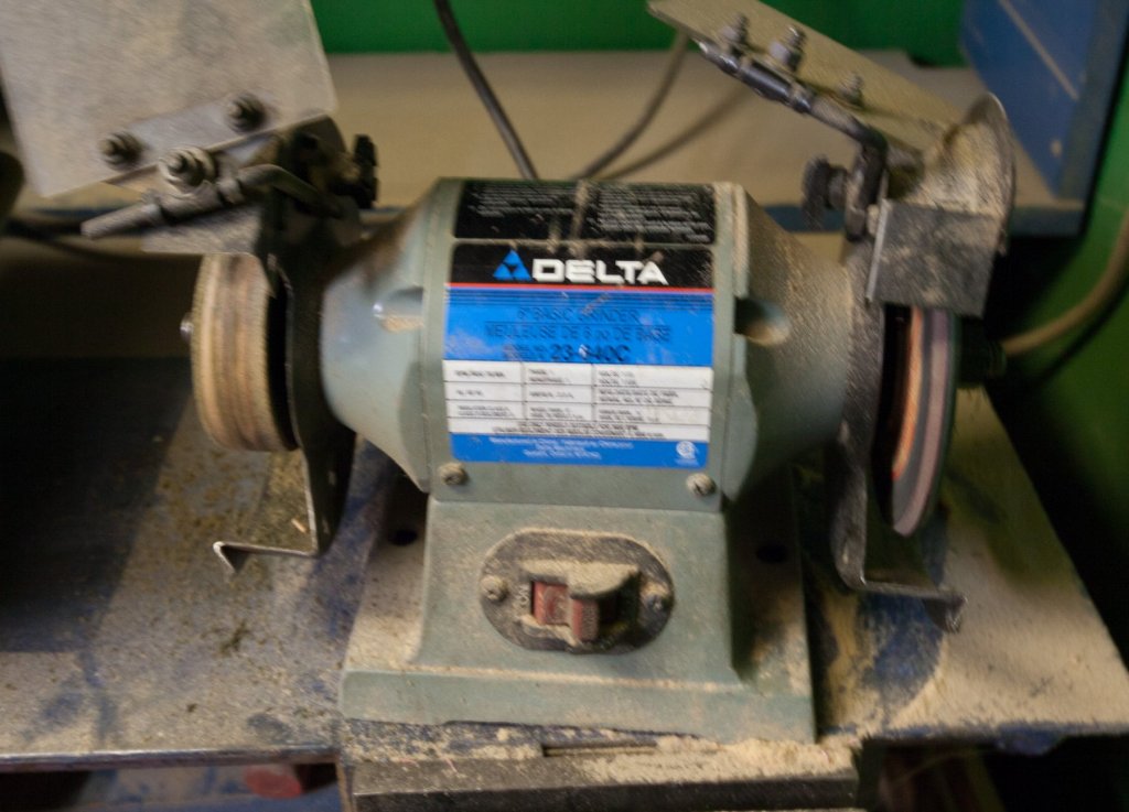
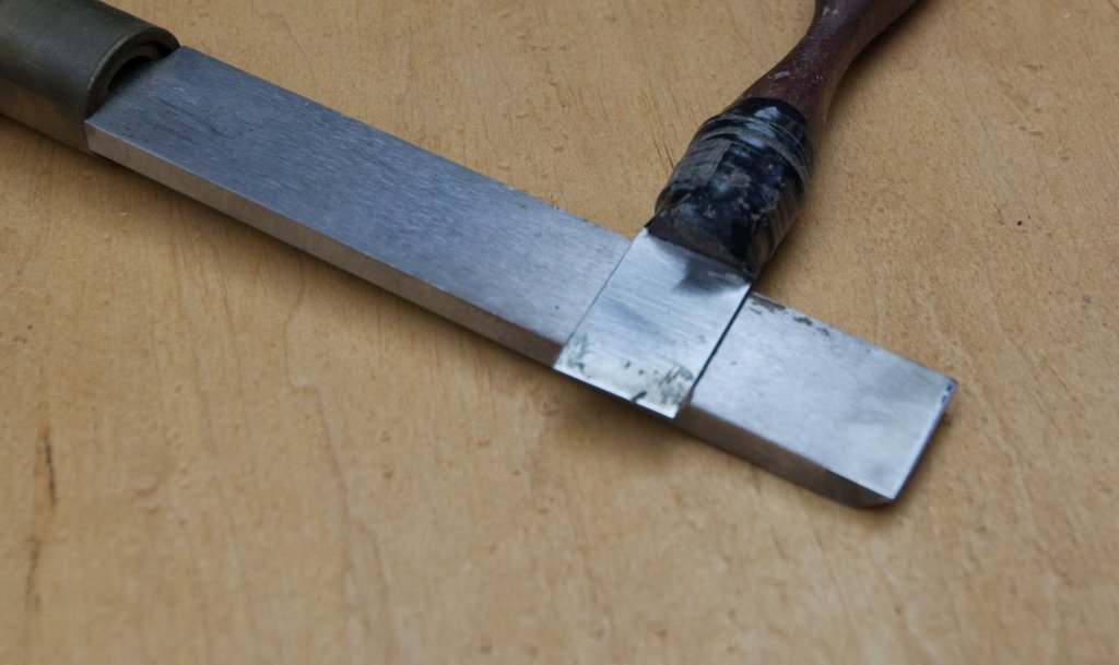
TO BEvel OR NOT Bevel Sharpening metal can be done by hand or by machine. It can be done fast; 1- Sanding a new blade on a metal sanding blade Or it can be done slowly like : 2- Finishing the sharpening on a surface grinder 1/10000 inch at the time. Sharpening can be done by hand. When a small refresh of sharpening is needed : 3- begining with diamond stone up to about # 1000 4- to water stones up to 8000. It can be even higher with porcelain but the difference is minimal to the use. To finish in beauty; some passes on a leather strop is use to eliminate burs. 5- different additives with various grit# can help to increase the finish. The same job can be done faster mechanically or when a major regrind is needed. 6- Different kinds of abrasive wheel can be used depending of the intensity needed 7- Grinder with an adjustable angle is very helping to keep the blade without moving. Right side white abrasive, left side diamond wheel. Diamond are on the side of the wheels to have a flat surface. Because if diamonds were on the front of the wheel, the surface would be curved making the job harder to do. 8- For the finishing, different solutions more aggressive to begin and softer to finish. Felt wheels or cotton wheels with compounds. To clean these kind of wheels, I use sandpaper with a backing of wood and get rid of polishing compounds and at the same time it does resurface the front of the wheel 9- Leather wheels, hard rubbers 10- (Left side, little table to cut metal) right side 3M wheels, another kind of porous artificial rubber, I like this one very much, 3M made a very good job with this one. This is the best one for mirror finish, better and faster than felt or cotton wheels. Now the question to ask ourself is why would we add a bevel. In fact I think it would be better to ask ourself is where would we need a bevel? 11- Let’s suppose I want to make a turning knife. I will use O1 steel, tool steel, .25 X 1 inch and I will cut a 1 feet lenght. The cut will be at 90 degrees. If I sharpen the end and get rid of burs I will get a scraper, very efective to bring a plank straight., but it would be prererable with a thinner blade 12- To turn this scraper into a blade, I just need to put a bevel at one end of the blade. 13- To sharpen a drill bit, I use a drill bit holder (photo 5) 14- A milling cutter with a bevel? No it is more a relief angle wich is often added to help to reduce friction with metal 15- On the last picture, we can see on the left 1 of the knife that I prefer. Even if it is a knife, there is no additional angle close to the edge. This knife cut extremely well. In my opinion, for wood knives with narrow blades, there is no needs to a second bevel. By example if a cutting angle of 25degrees is made, adding a secondary bevel of +/- few degrees will absolutely not change anything in the cutting properties. We could try with a 25 and 30 degrees blade and very good is the one who can feel the difference. For the long blades, it is different. The 2 sides of the blade thickness have 1 angle and 1 of the reason to save time, a bevel is added. To give an example. Few weeks ago I did grind the knives of the jointer with the surface grinder. Blades are about 6 inches long. There is a bevel on the blade. To sharpen I only need to sharpen the bevel. The rest of the side of the angle does not need to be sharpen because his single purpose is to hold the blade. By grinding the bevel only; it saves a lot of time. To sharpen just the bevel of the blade takes by example 2 minutes. If I would grind the complete angle, it would take 2, 3 or 4 time longer. On the contrary with a narrow blade, if you sharpen the complete side and then you add the sharpening of a bevel, it will take much more time and you will risk, if you do not use a guide, to run the previous job. But if you only grind the bevel and not the complete side, then you could save some time. But because a narrow blade has by definition a very small area, there is not much time to save…


-
Mark, I bought mine probably 25 years ago. I do not remember where.
-
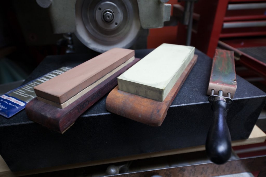
I use this one. Wood with water on it works fine.
-
Mechanically is surely easier. I guess there are no laws to do or not to do a bevel. It could be like a personal preference. I do not use any guide for sharpening, I sharpen the whole surface (for the small knives) and by hand it would be difficult to do a perfect bevel. What are the advantages to do a bevel? For a knife with a small angle, the thickness of the sharpened edge would be smaller, making it a bit thicker would help to have a more stable edge. Also, using a leather strap helps to realign the edge which when observed at magnification have a slight S curve. Additionally, a leather strap is the finishing touch like using, let's say 25000 grit. And finally a leather strap will eliminate burrs. Recently, I saw a sculptor in a show. He sharpened perfectly smooth and shiny a knife with a coarse electric bench wheel and to get rid of bur at the end he used a 240 grit. Results were amazing. He got good results using a light pressure. There are hundreds of possible combinations to sharpen a knife, we just have to find one which suit our needs.
-
I would say it depends of the types. To keep it simple, let’s make a comparison with only 2 kinds; long and small surface blade. Knives few inches and more, usually have a bevel and it is faster to sharpen only the bevel. In fact it is only the bevel which is sharpened. Other types of knives, with much shorter surfaces, like Cabinet makers knives usually do not have a bevel and all the angled surface is sharpened. There is no time saving to add a bevel on a small knife. Also it would be difficult to recreate a perfectly aligned bevel each time.
-
Pencil case definitely has a nice curve! Very nice gifts, you made, Mike.
- 968 replies
-
- 5
-
-
- hahn
- oliver cromwell
- (and 1 more)
-
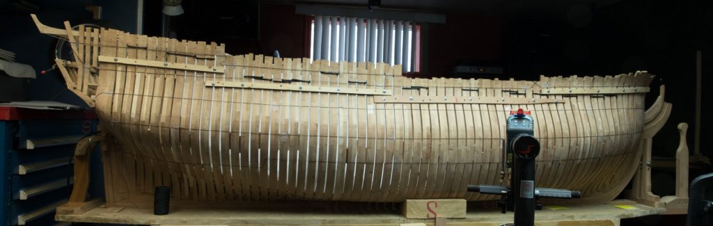
I see 2 ways to build a model: according to the plan or to the model. I always build on the model because if I would build according to the plan, It would never fit on the construction site.
-
Impressive work hjx!
-
I guess it could be done... but not by me. It would have to be vacuum by parts and then assemble by appropriate glue. What would be the workability, better or worst. The question is in fact if possible would it be worth? It is not sure. The more model ship I build, the more I realize that distortion happens as soon as frames are assembled and too much pressure is used in squeezing the frames to fit in the length of the ship. I think it is very important to realize that excessive pressure at this early stage is a sure way to have problems. I guess I prefer to spend 1 additional month to try to understand how to assemble frames and try to fix as much as possible problems at this early stage. On this forum many members came with innovative solutions to fix this problem and the addition of all these solutions is probably the key to get a stable frame assembly. The only thing which is missing now is the chapter regrouping all these solutions...