HOLIDAY DONATION DRIVE - SUPPORT MSW - DO YOUR PART TO KEEP THIS GREAT FORUM GOING! (Only 13 donations so far - C'mon guys!)
×

Gaetan Bordeleau
-
Posts
1,307 -
Joined
-
Last visited
Content Type
Profiles
Forums
Gallery
Events
Everything posted by Gaetan Bordeleau
-
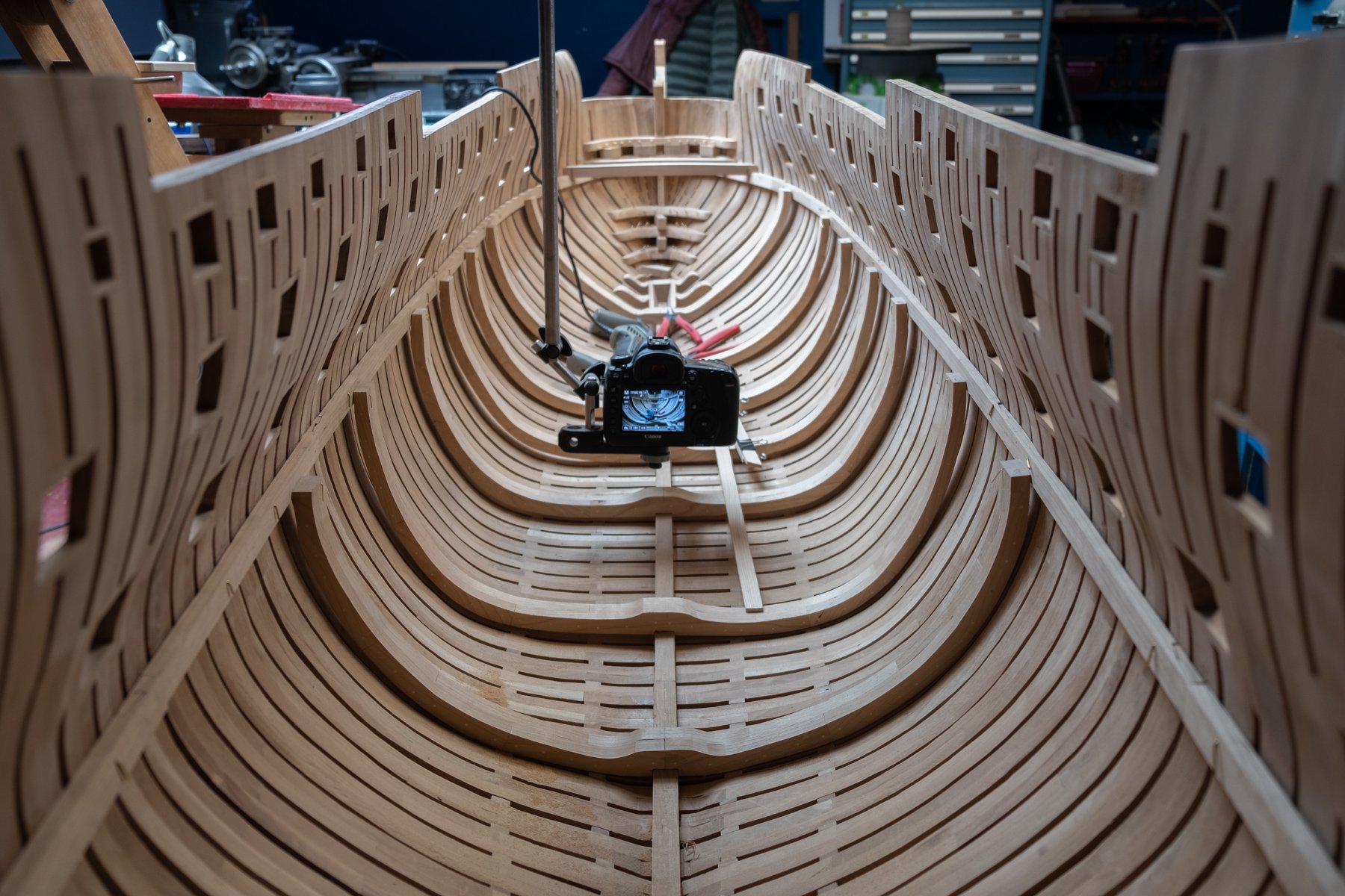
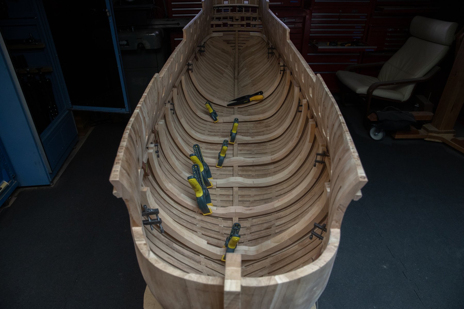
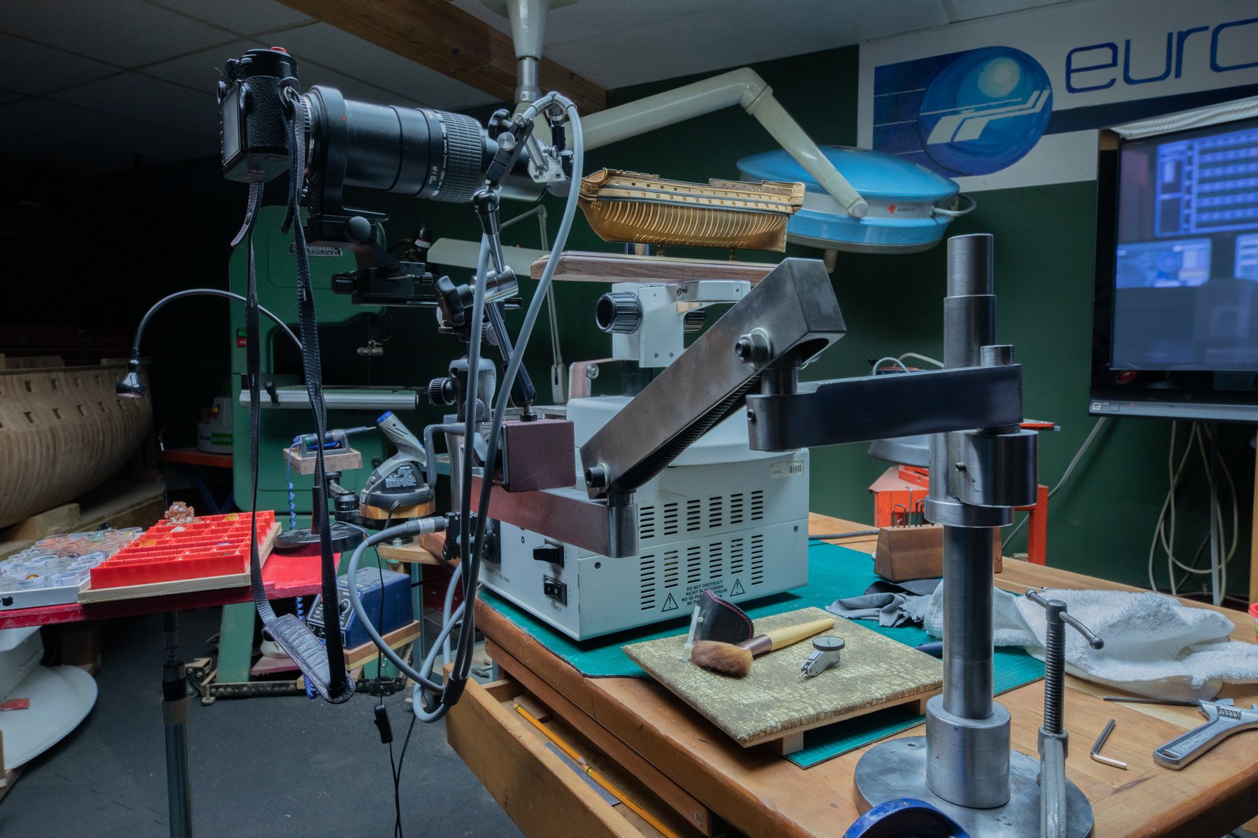
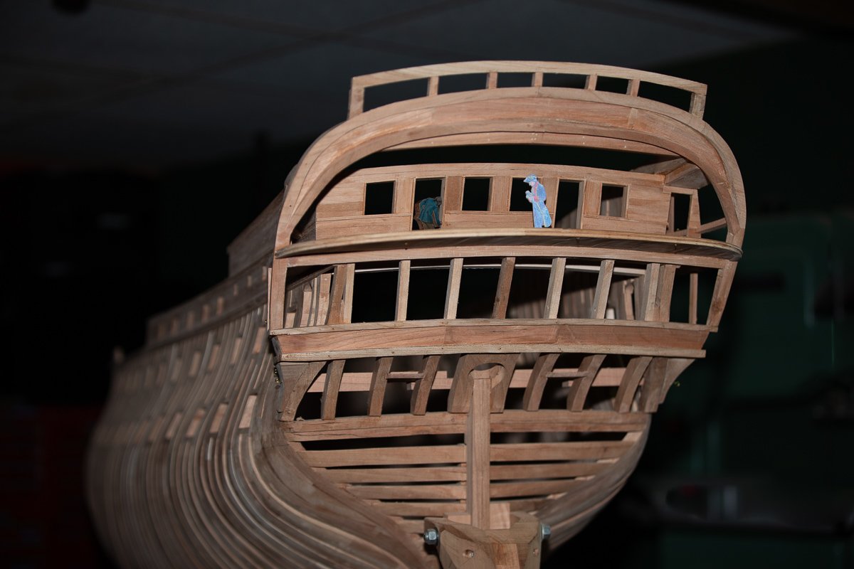
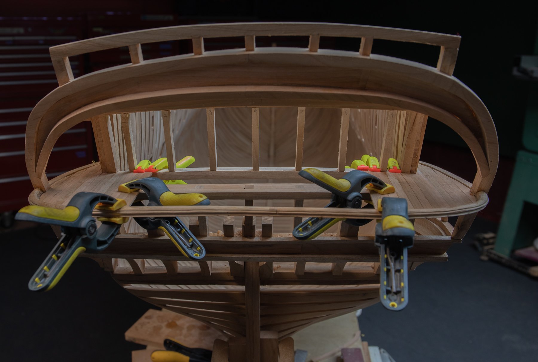
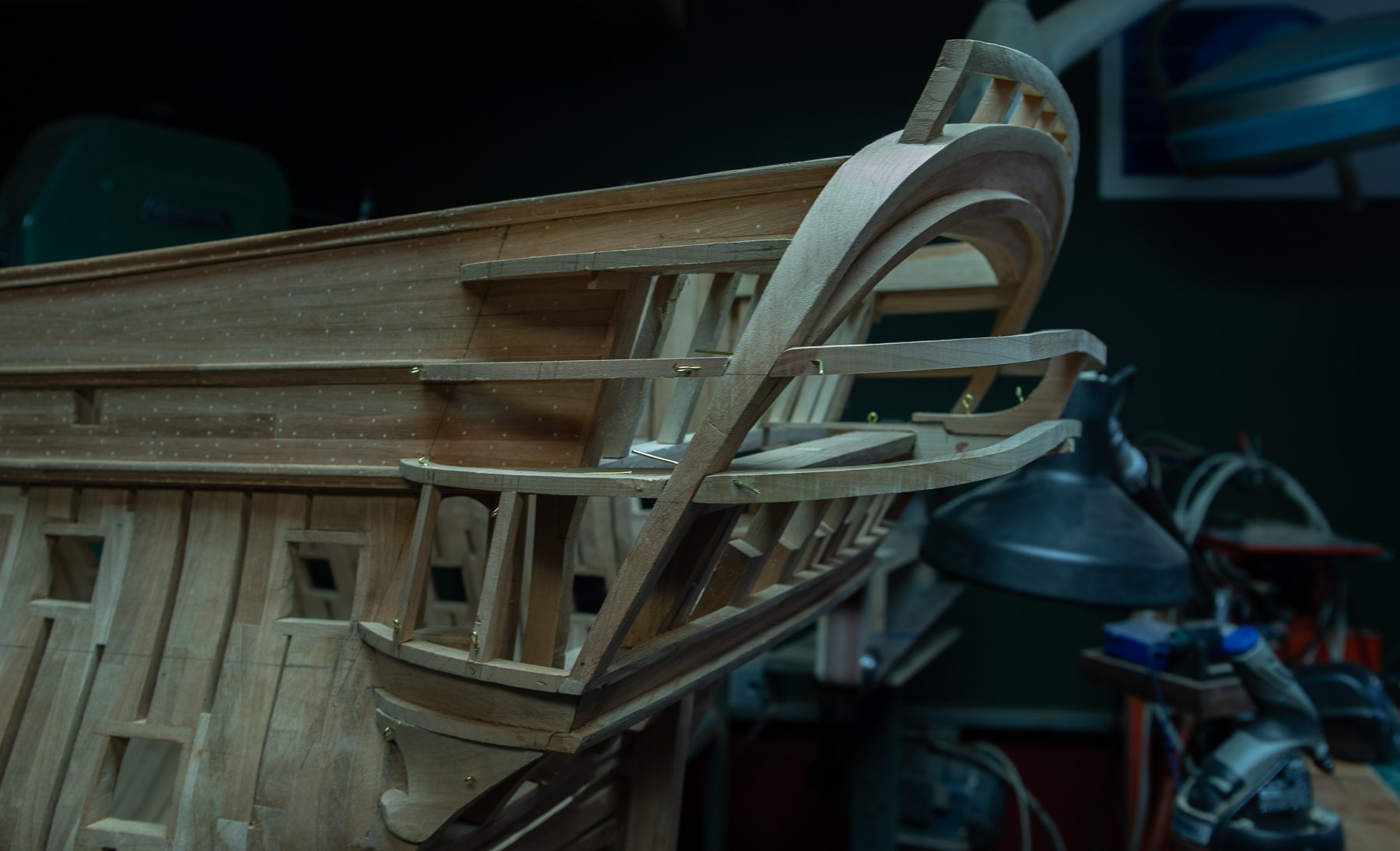
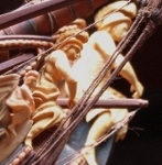
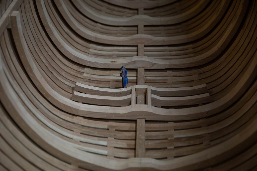
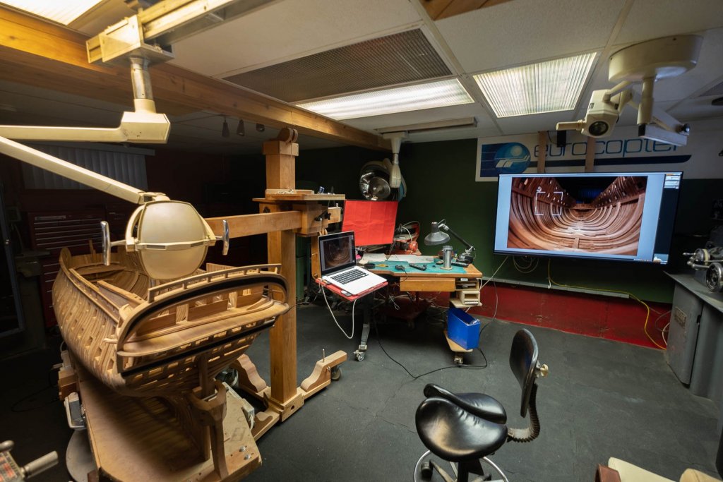
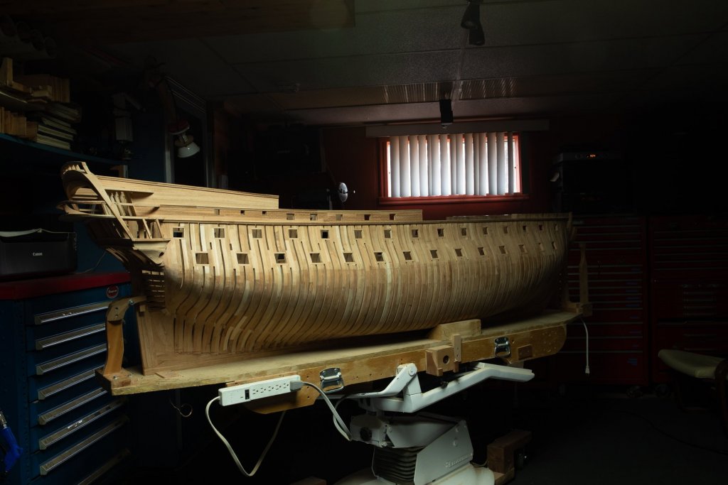
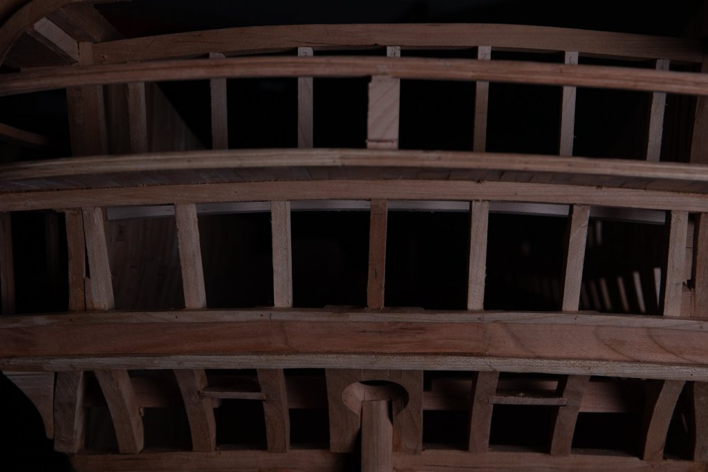
 Glued most parts except the rail where the deck beams will rest. These rails must be still removable to be able to cut notches for the deck beams from the first deck later. Half frames rest on these rails and to glue the half frames , a spacer is added under the rails so that the half frame can be glued somewhere. Also the setup to take photos is now completed with a new tv. This way, it is very easy to observe very closely construction details photos
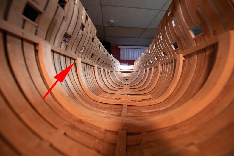
-
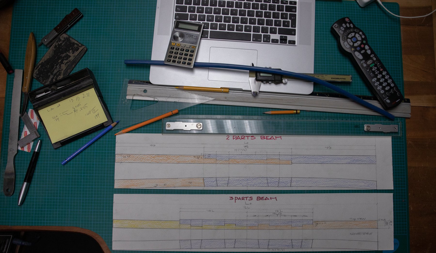
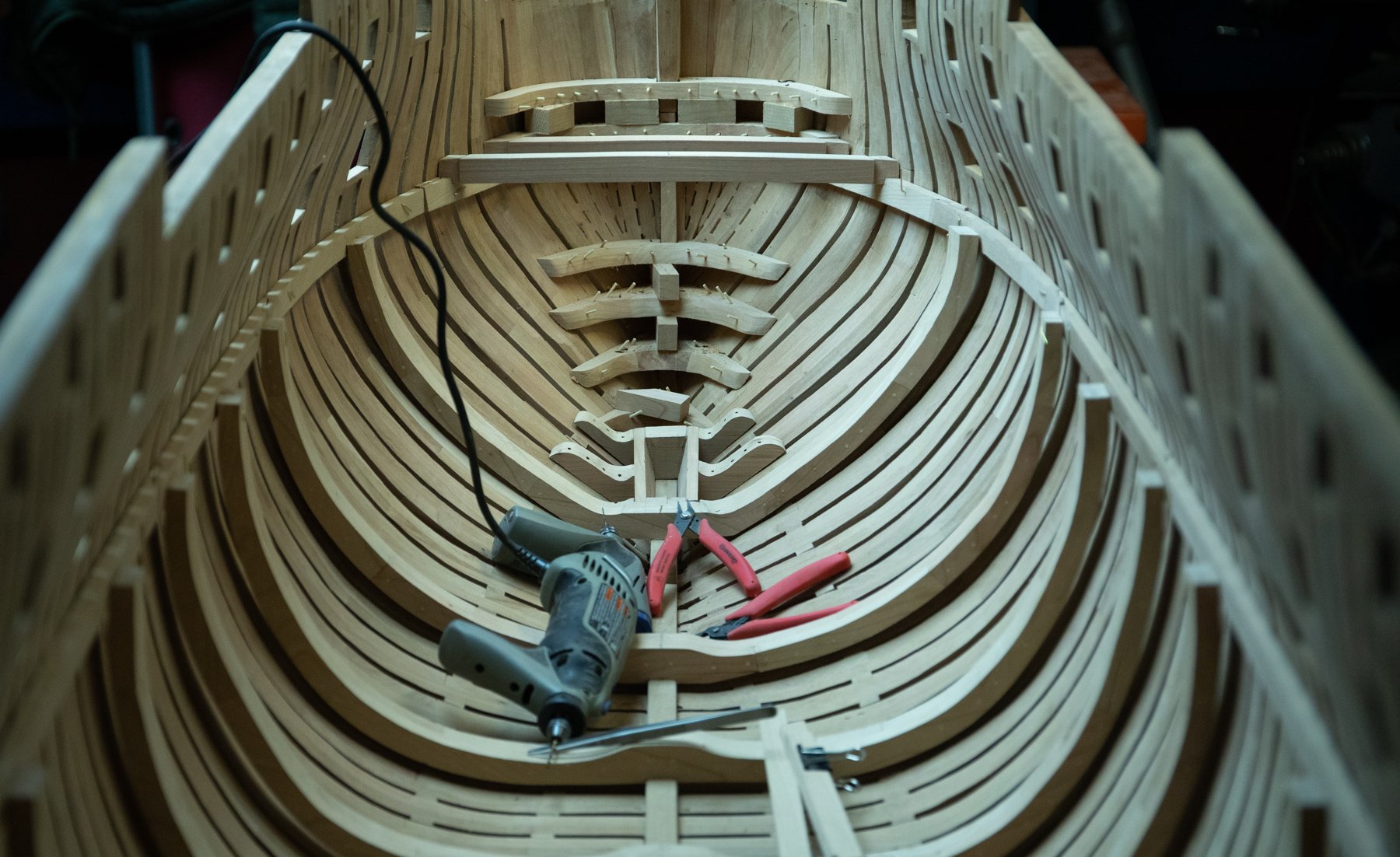
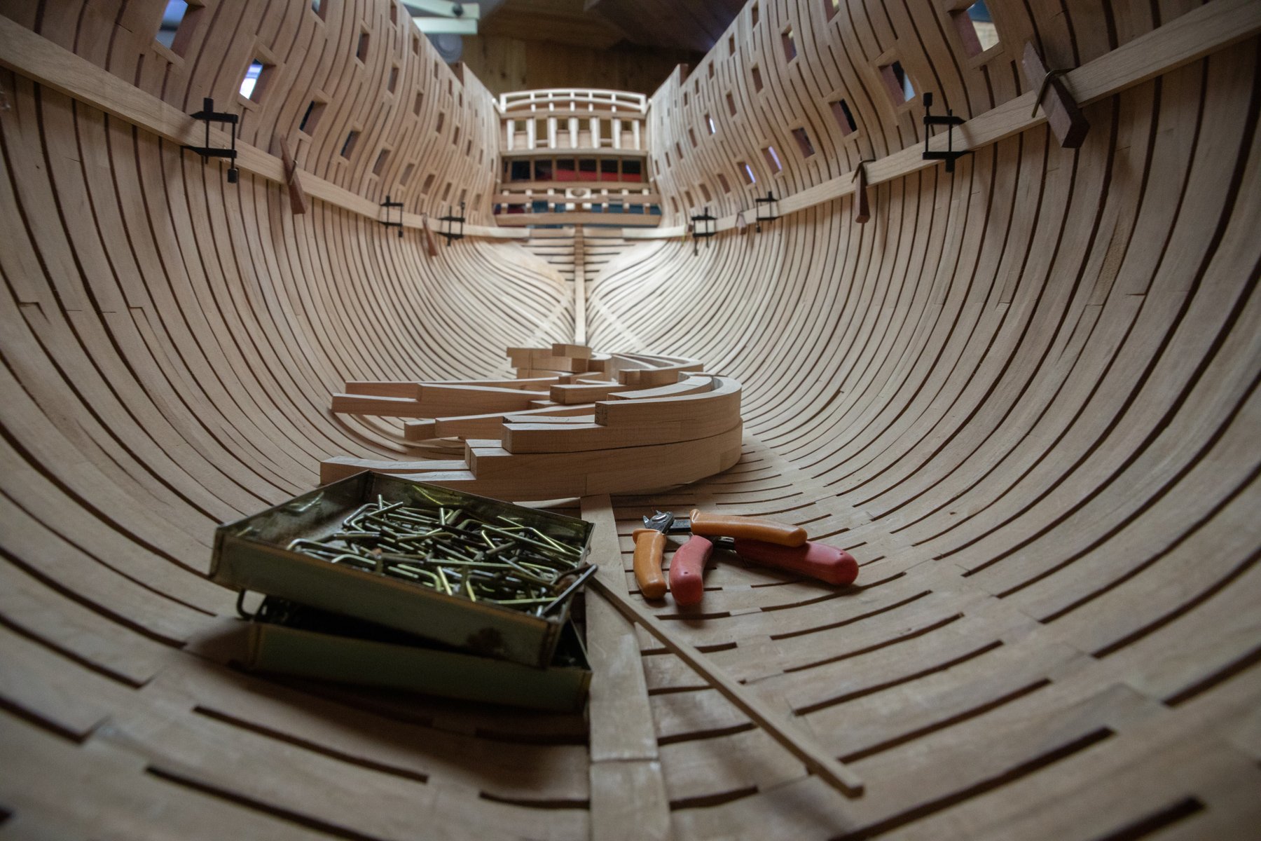
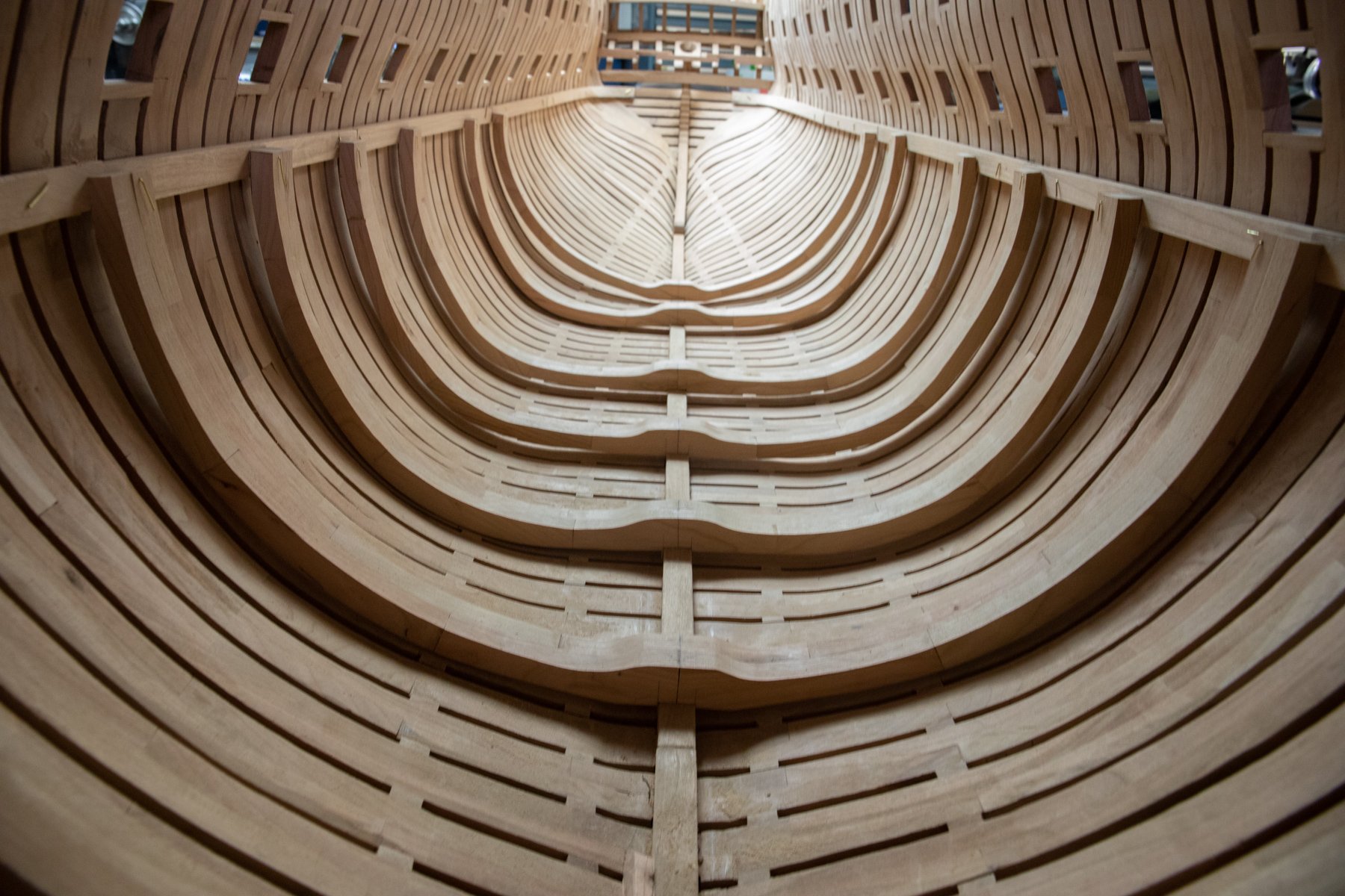
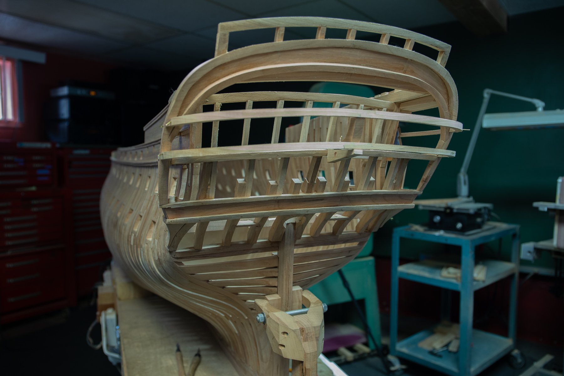
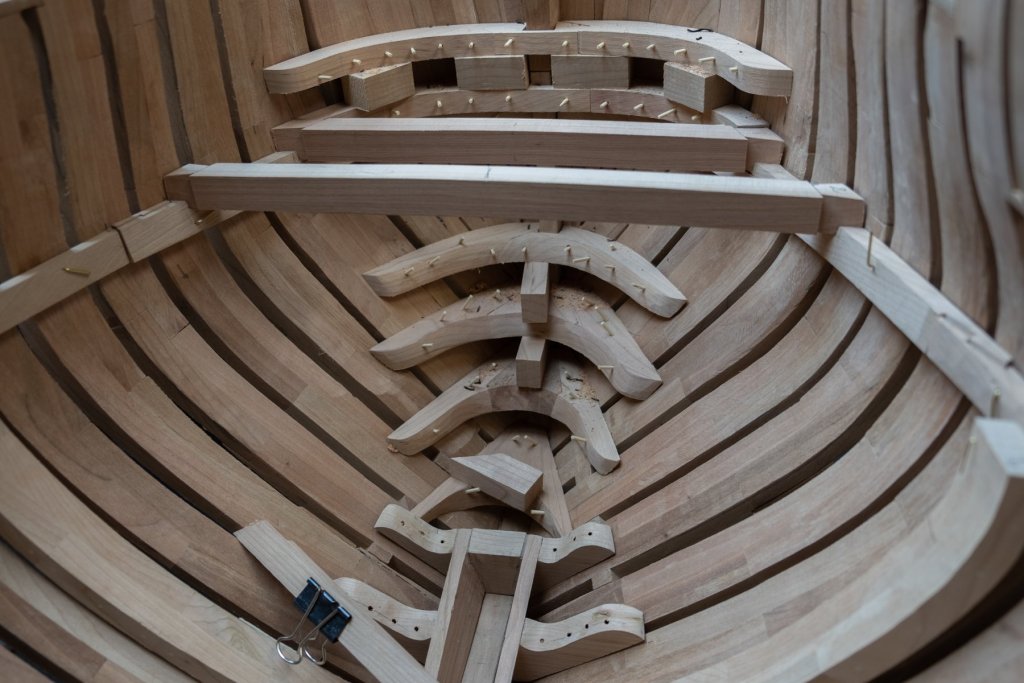
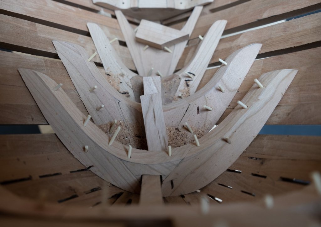
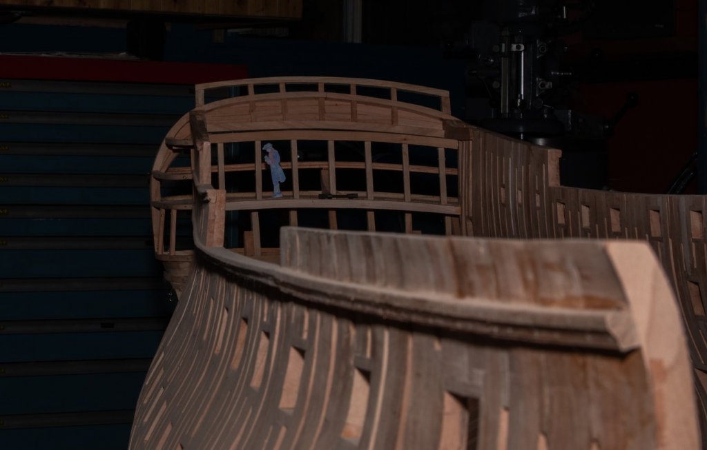
Installation of reinforcement pieces. The easy way to assure parallelism between each one is to set a spacer. 2 of these have a double use: they will also receive the planking of the false and first deck. Deck beams of the first deck will rest on a large plank on each side of the boat. Each frame will have 1 notch each side to sit them. The first deck is the one withe the greater span. For this reason, some of the frames will be made in 3 parts with taper notches. This is a great method to assemble beams. Probably with the weight of the parts only, it would be enough to fix the parts of the beam. I remember the first time I tried it, I was surprise how strong locking this mechanism is able to perform; the same way as a taper sleeve but because the parts are assembled in an arc additional lateral strengths comes to lock even in a stronger way the assembly. Depending also from the needs, there will be beams from 1 part, example the first 2 in front. beams made from 2 parts will also be include in the first deck depending of the needs. With the fabrication of the camera studio stand, it will be easy to insert a full frame camera inside. One of the advantage is that it is easy to set the camera parallel to the model. I will try to give access as much as possible inside. For this reason, deck and wall planking will be install only in essential circumstances. In a way there will be as less as possible longitudinal planks but more perpendicularly to the keel. Parts are temporary fix until all the notches to receive the beams of the first deck are done. I got an answer from Lee Valley and Veritas for the detail knife. Here is a part of the last paragraph: ''We also have some other design we are working on. In order to avoid any conflict your product submission will not be reviewed by our designers. SO, I can only hope they can produce a sharp knife with their wood plane blade. While this time, when I will want to have a sharper knife, I will regrind one of those blade in a V shape or may be I could do a knife blade from a half wood plane blade.


-
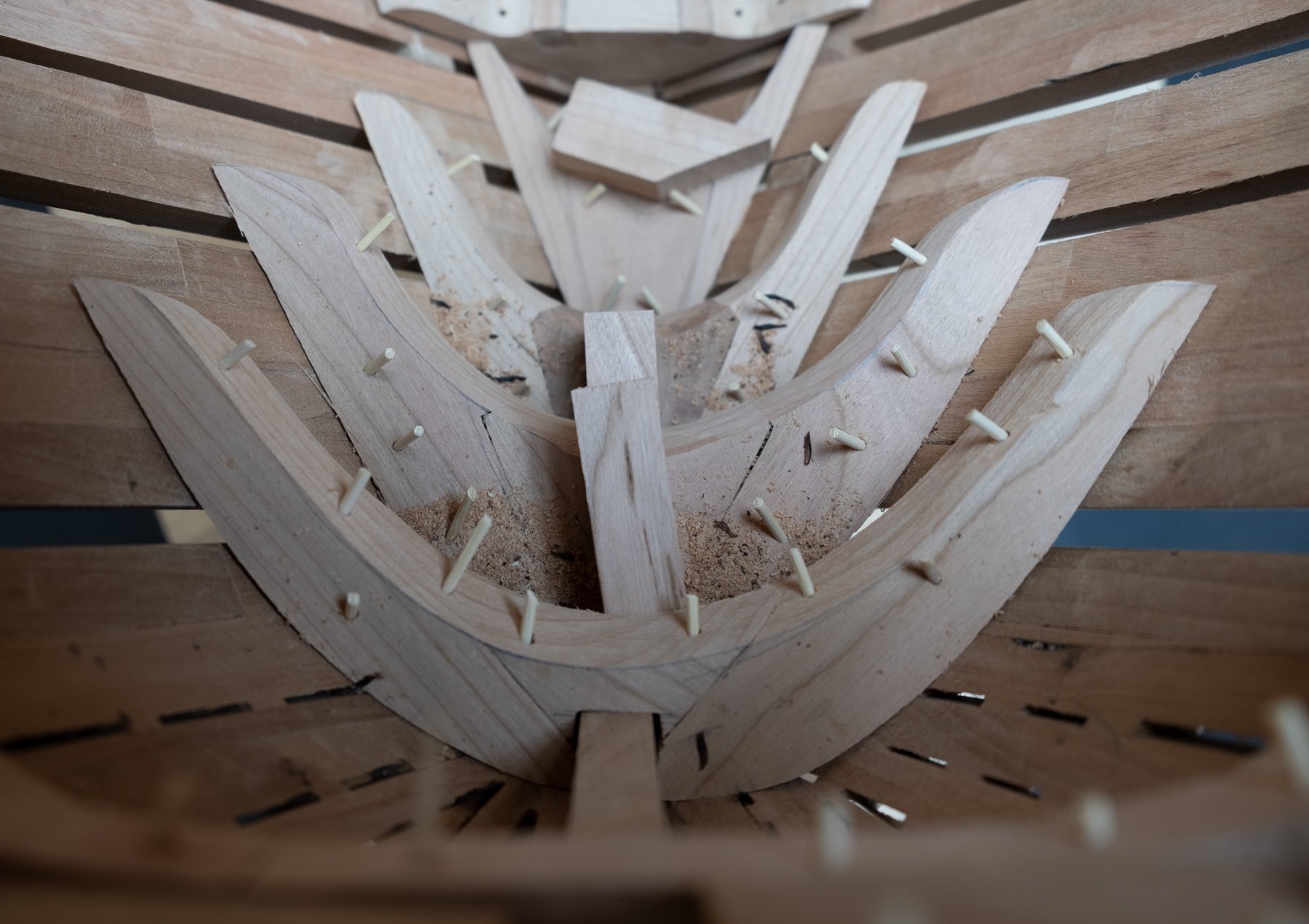
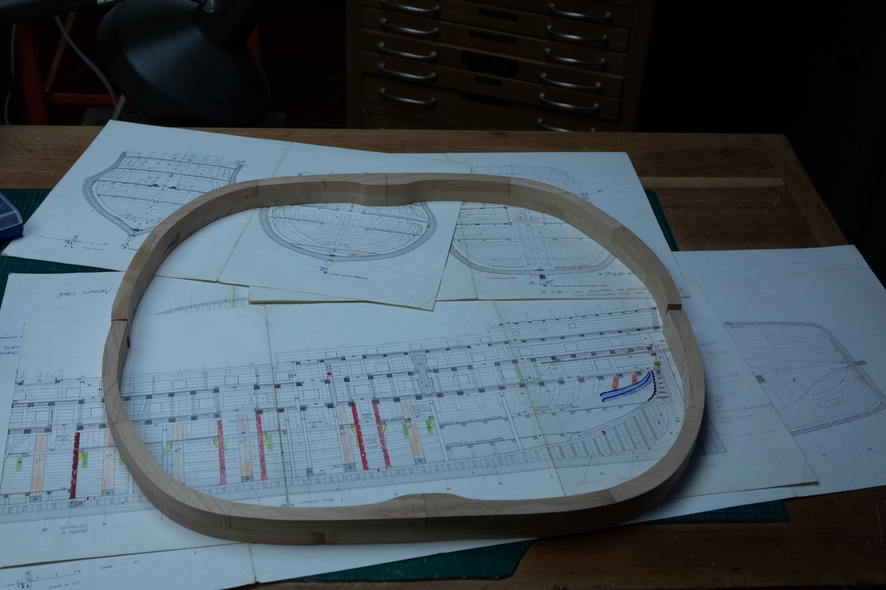
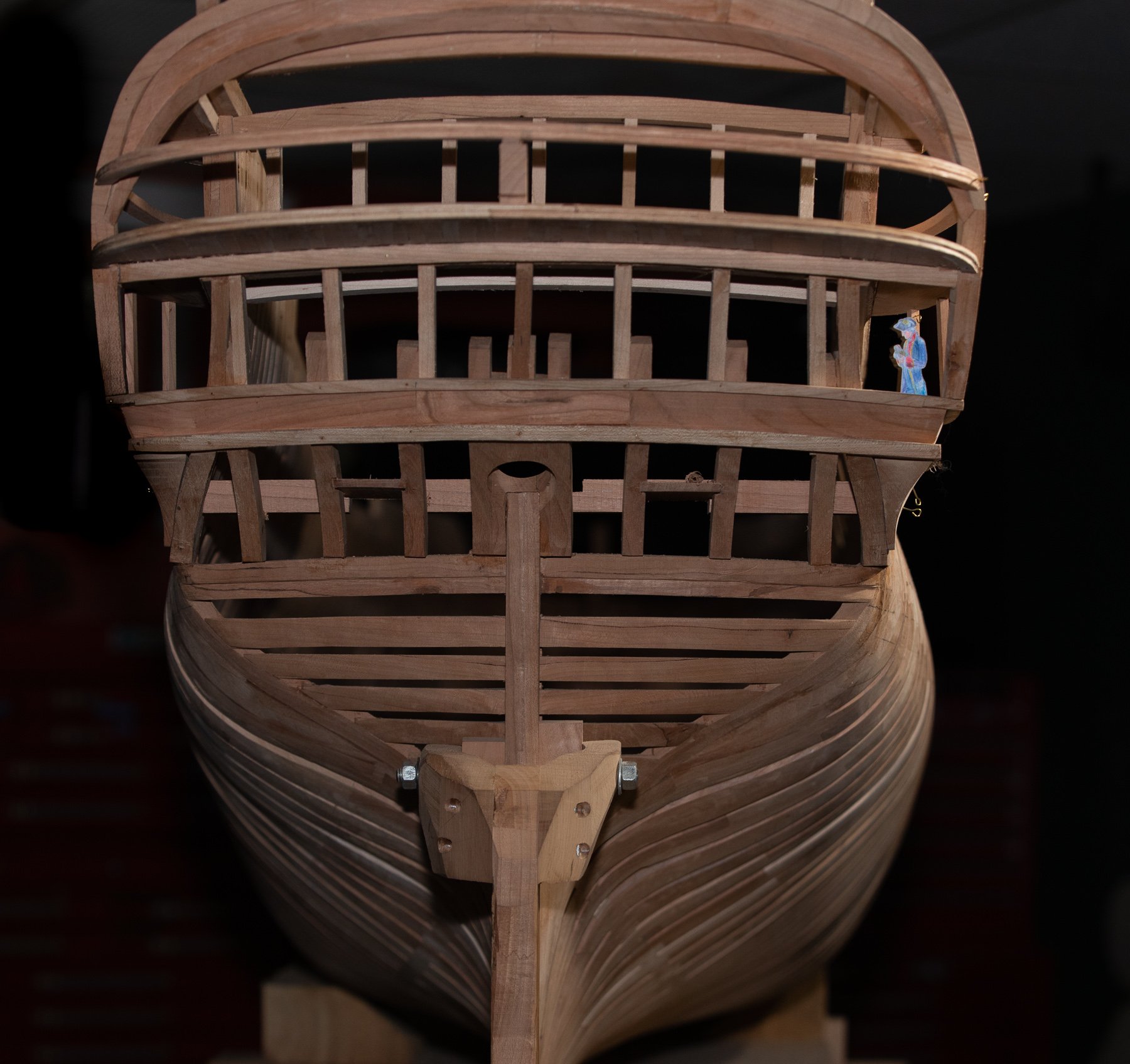
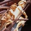
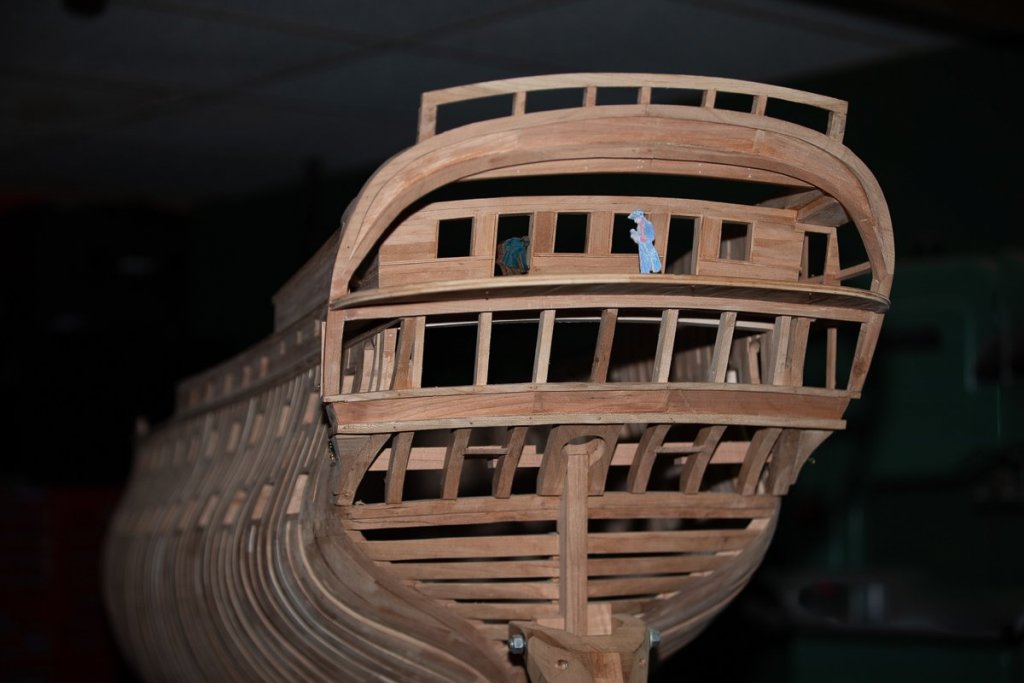
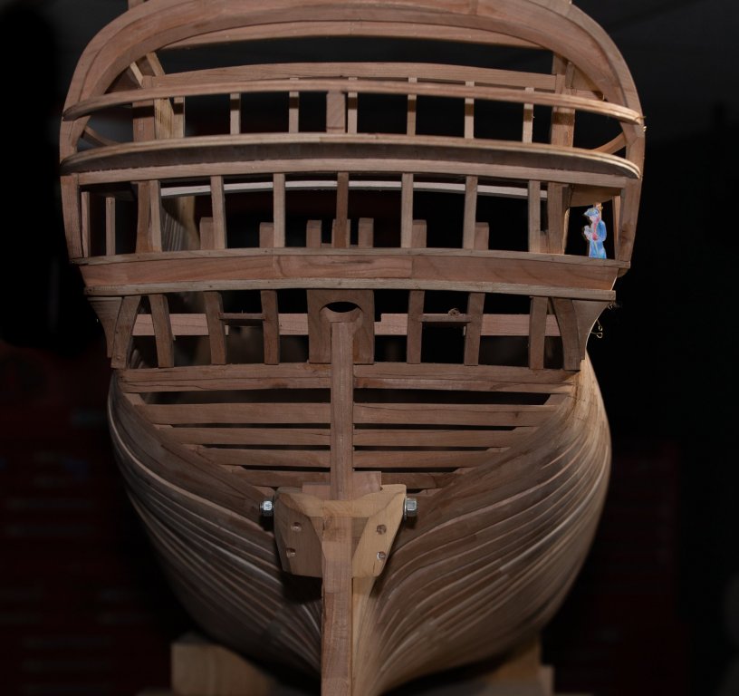
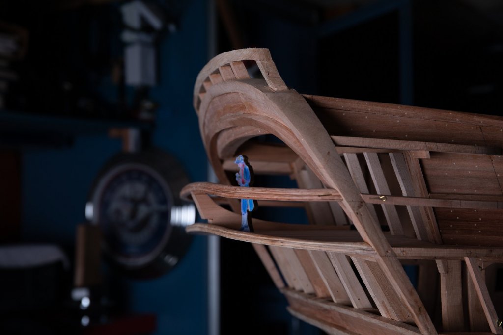
2019, the beginning of the construction inside the model ship. First part, planks to support the deck beams, very easy to position; the height in reference with the gun port openings is the same everywhere. Followed by 7 inner frames. Still other parts to do before to fix everything.


-
Lighting the Work Area
Gaetan Bordeleau replied to Richmond's topic in Modeling tools and Workshop Equipment
https://www.homedepot.ca/en/home/p.100w-equivalent-daylight-5000k-a19-led-light-bulb-2-pack.1001006062.html your best bet is probably to go to a big home store and choose some kind of LED light bulb Lumen and are written on the box. In this example 1500 lumens and 5000K
-
http://www.leevalley.com/en/wood/page.aspx?p=42607&cat=1,69168,69174&ap=1 the beginning of the solution: PM-V11, 2 blades for $60.
-
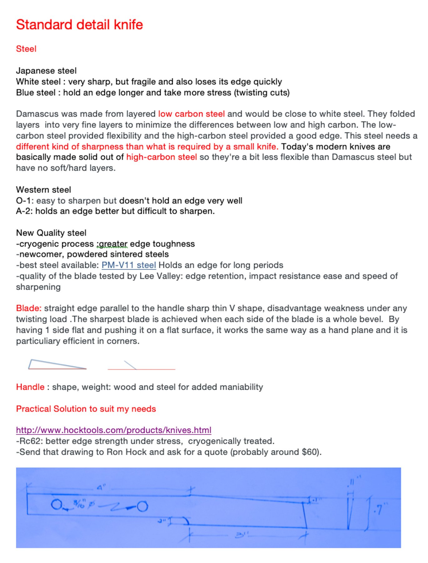
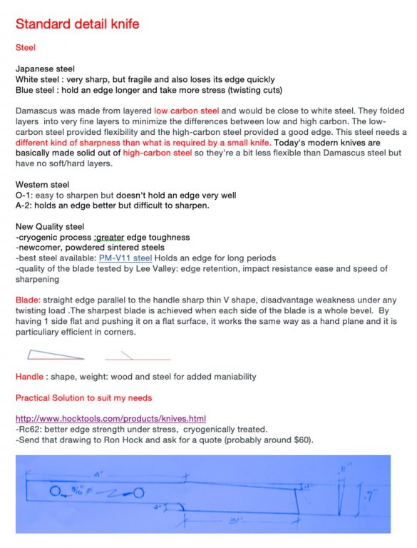
3 things: Unfortunately, here is what Ron said: "I hate to disappoint but we don't have a good way to make this for you. Sorry, no quote.'' Vossiewulf, I am sure you will agree: there are sharp knives but there is also extremely sharp knives May be after Christmas I will write to a company to see if they would like to produce a good Standard Detail Knife which would be extremely sharp. Actually they do not really have any. I think that PM V11 steel would be a very good choice!
-
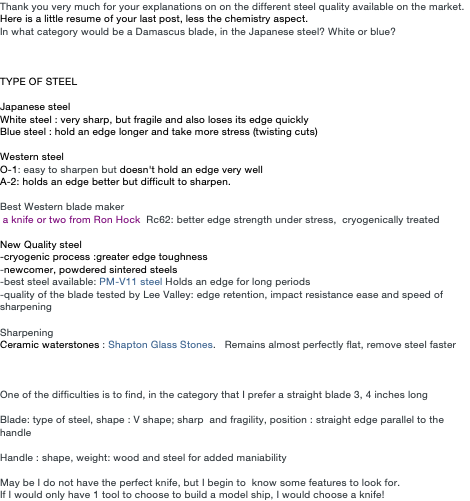
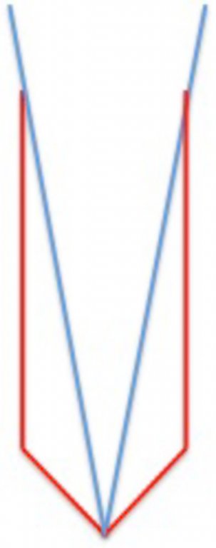
Thank you so much Vossiewulf to share your knowledge. You have reoriented me about steel. I thought that Damascus steel was the best, but I now understand that high carbon is one of the key. I draw a very simple shape for the next Standard Detail Knife and I will send it to Hocktools.
-
micro drill adapter for mill
Gaetan Bordeleau replied to michael mott's topic in Modeling tools and Workshop Equipment
Higher the speed, the smoother surface, a router bit acts the same as a milling cutter. Same idea with my wood planer; 2 speeds: the higher for finishing. At the opposite if you go too low, the knives will not cut as well; they will want to tear in the wood, especially at the edges Proxxon has a small mill that runs 20,000 rpm which is perfectly fine. Some model maker prefers to use a mill for wood at 5000 rpm... the only good reason I can see is because of the many accessories of other brands. When I can, I prefer to use aluminium where the cutters plunge like in butter. When strength is not a factor, I prefer to use high density plastic, very easy to turn and high degrees of accuracy can be reach. -
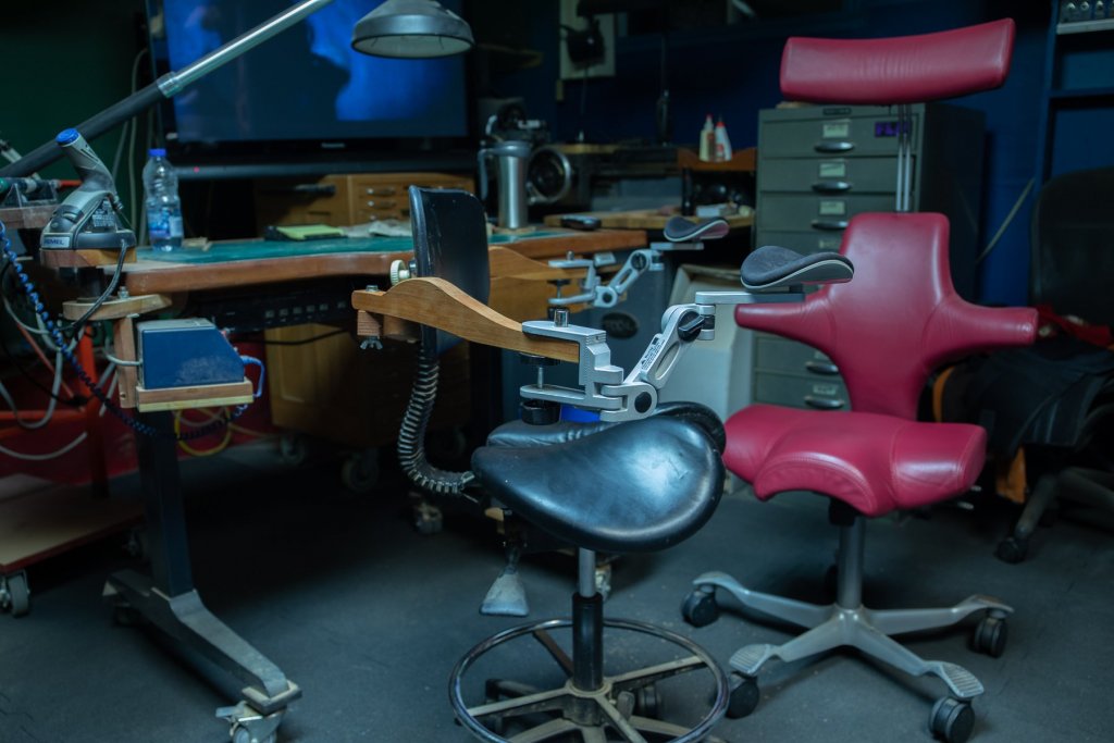
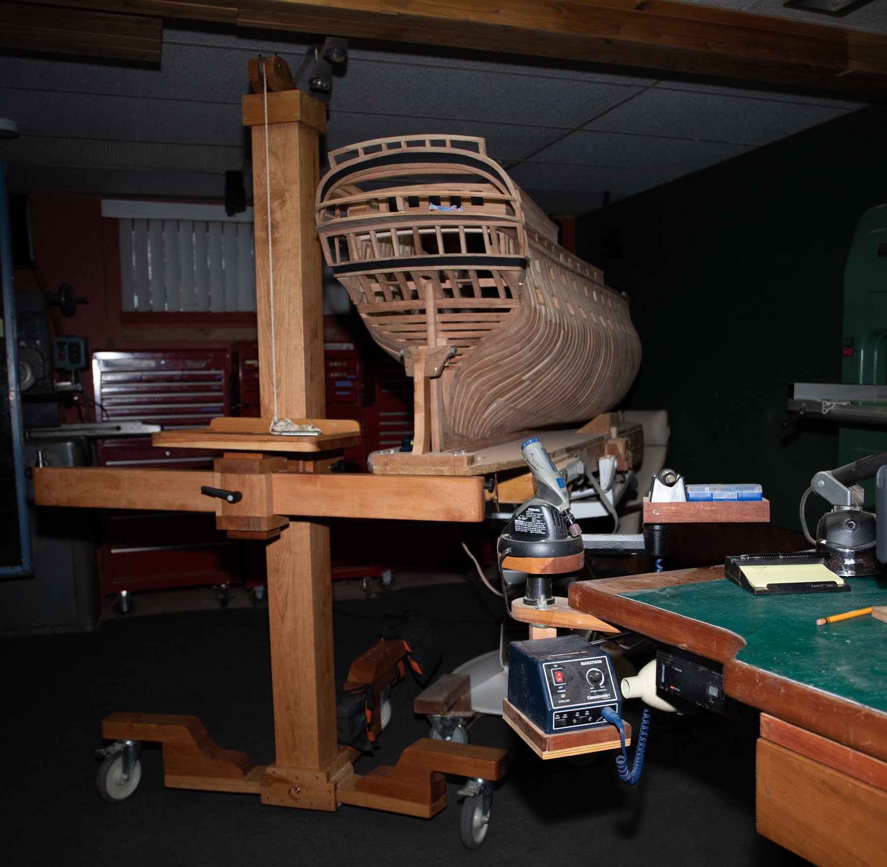
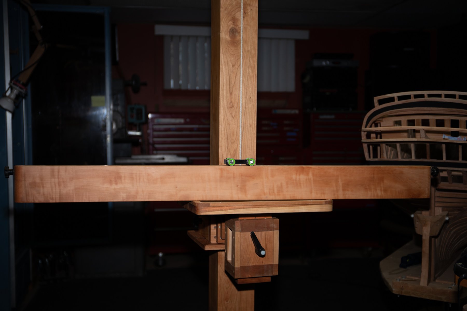
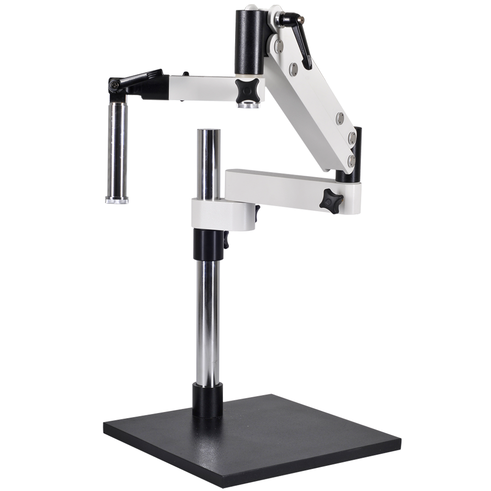
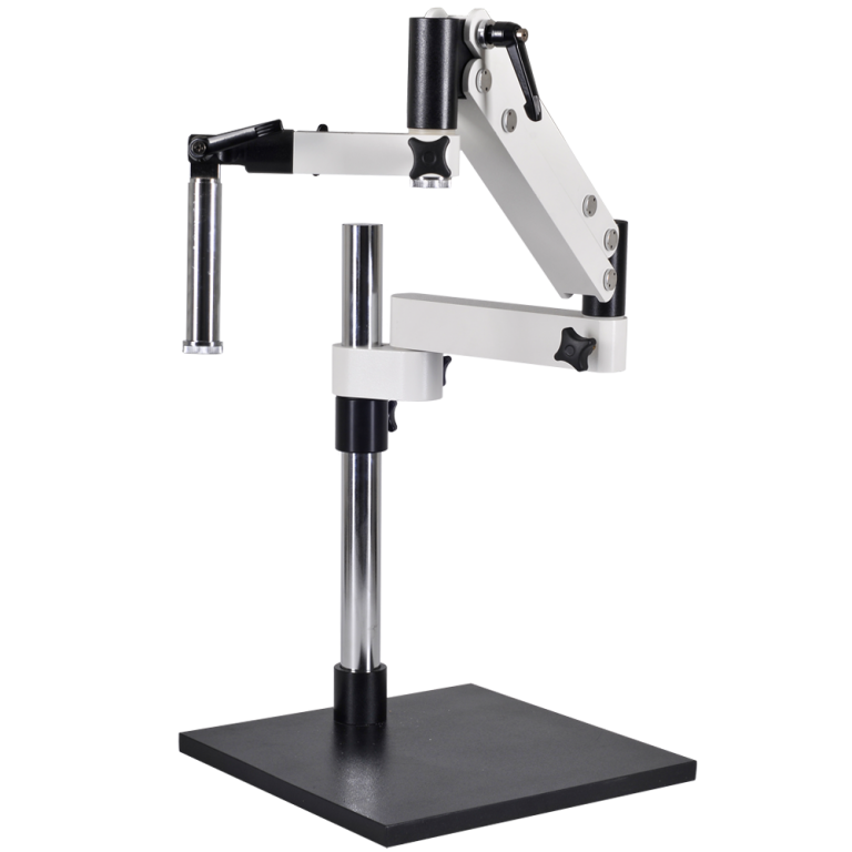
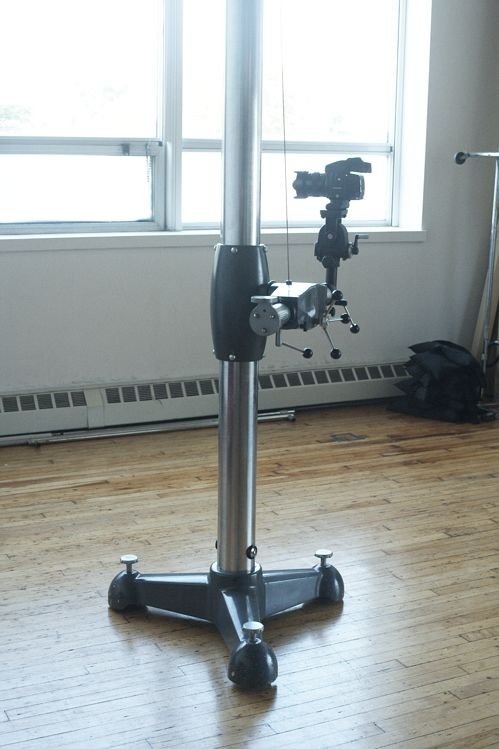
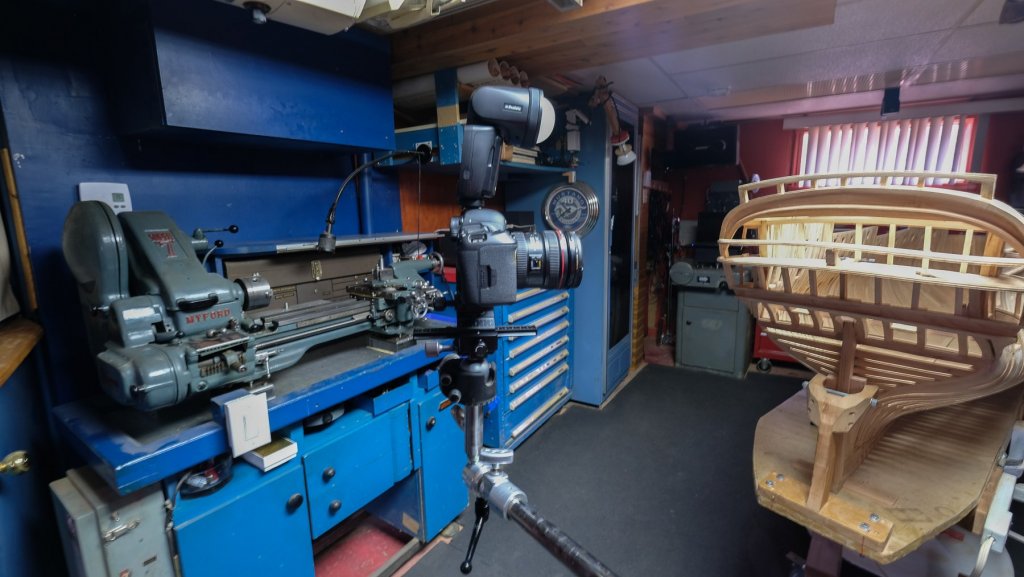
Yes Carl, in fact I did it for the microscope. I took the idea from a Microscope arm support like in the photo. This is my actual set up. I did try about 10 setup before with many camera tripods but I wanted to simplify so everything fits on the table. In macrophotography, stability is a must. In the future, I would like to get a studio camera stand, something like this old model from Cambo. Very nice model but I doubt I could find one like this!!!
-
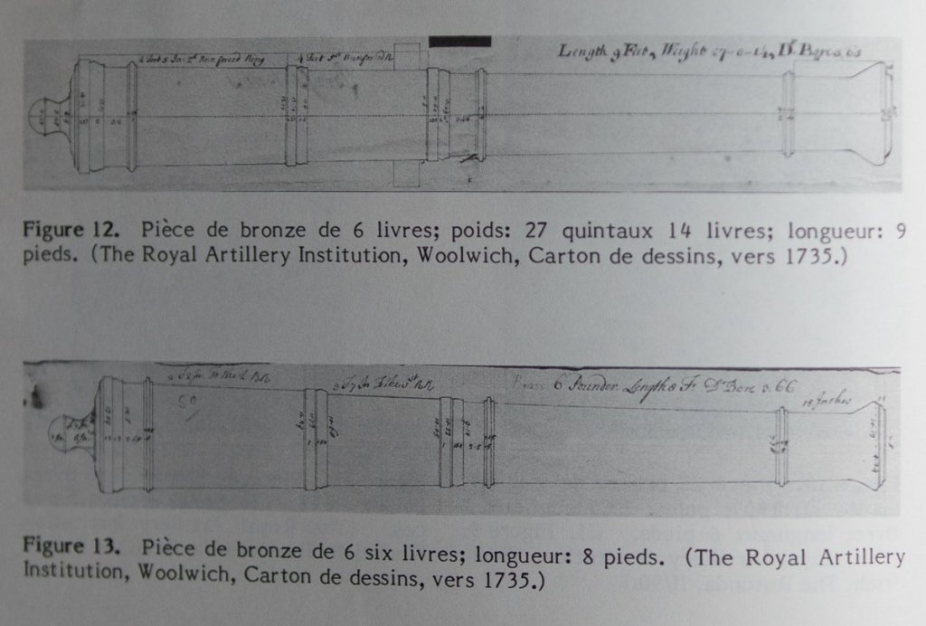
I have drawings of 1735 for 1- 3 -6 - 12 -18- 24. ex.
-
Wall construction

-
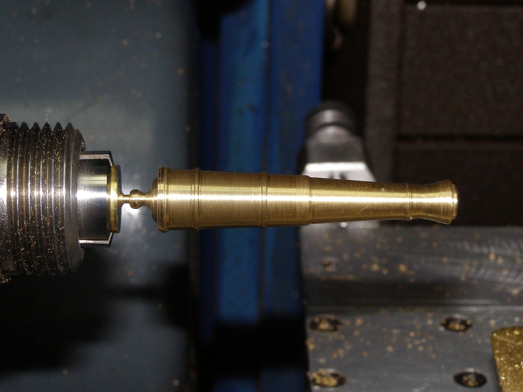
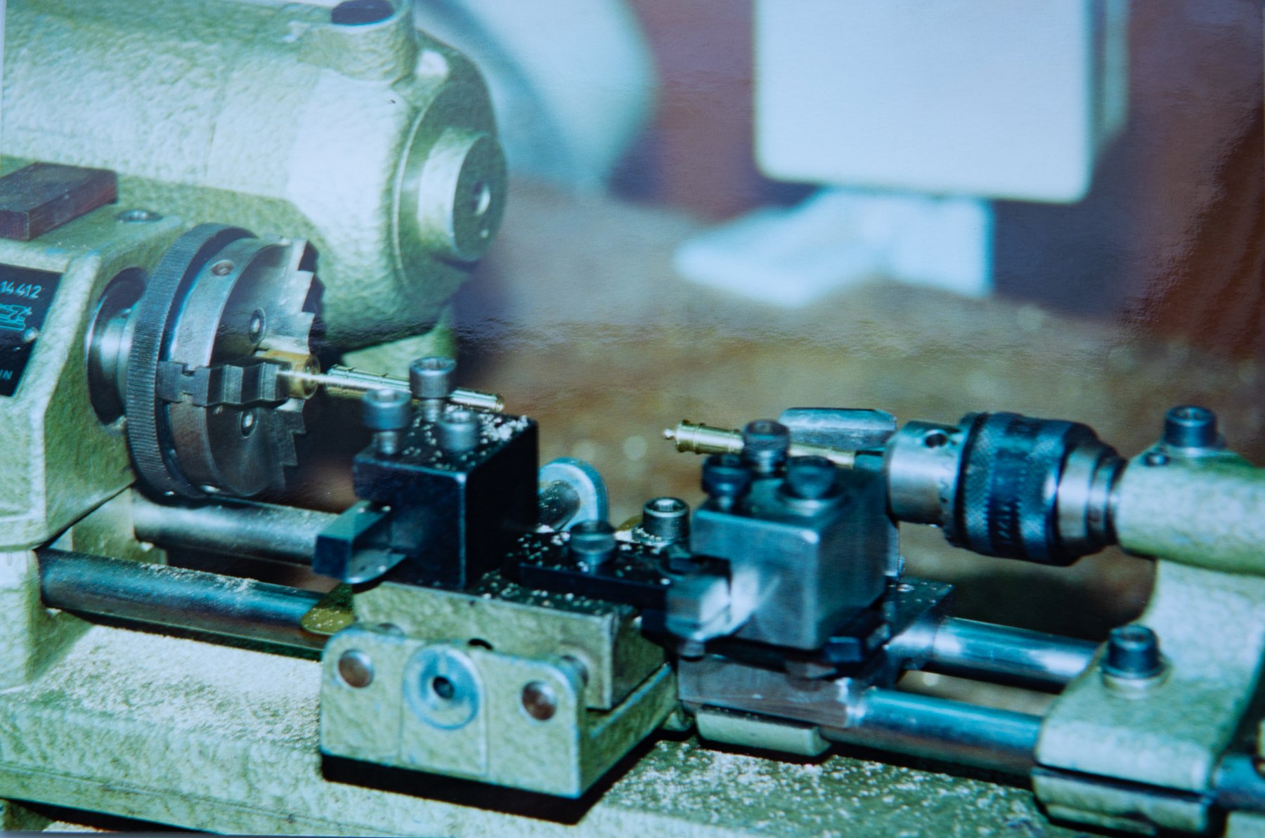
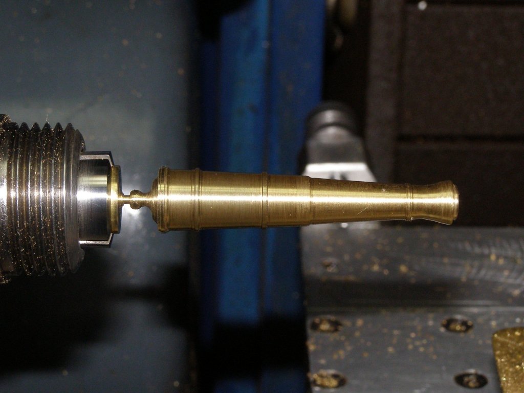
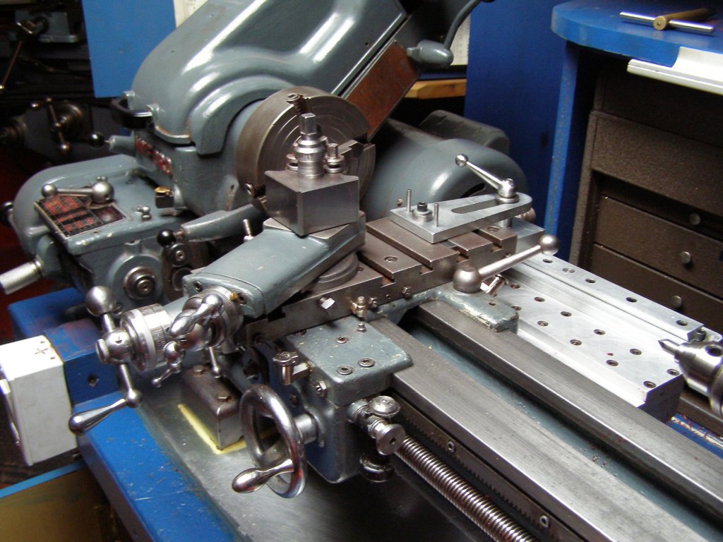
Ed is right we use the same method, with some variants; he gets the taper from the head, I get it by an attachment, I turn from the opposite end because it is easier to center the hole for the guns balls. The most important is that it is made by steps, specializing in one part at the time.
-
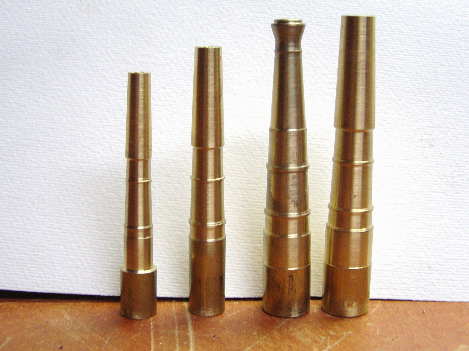
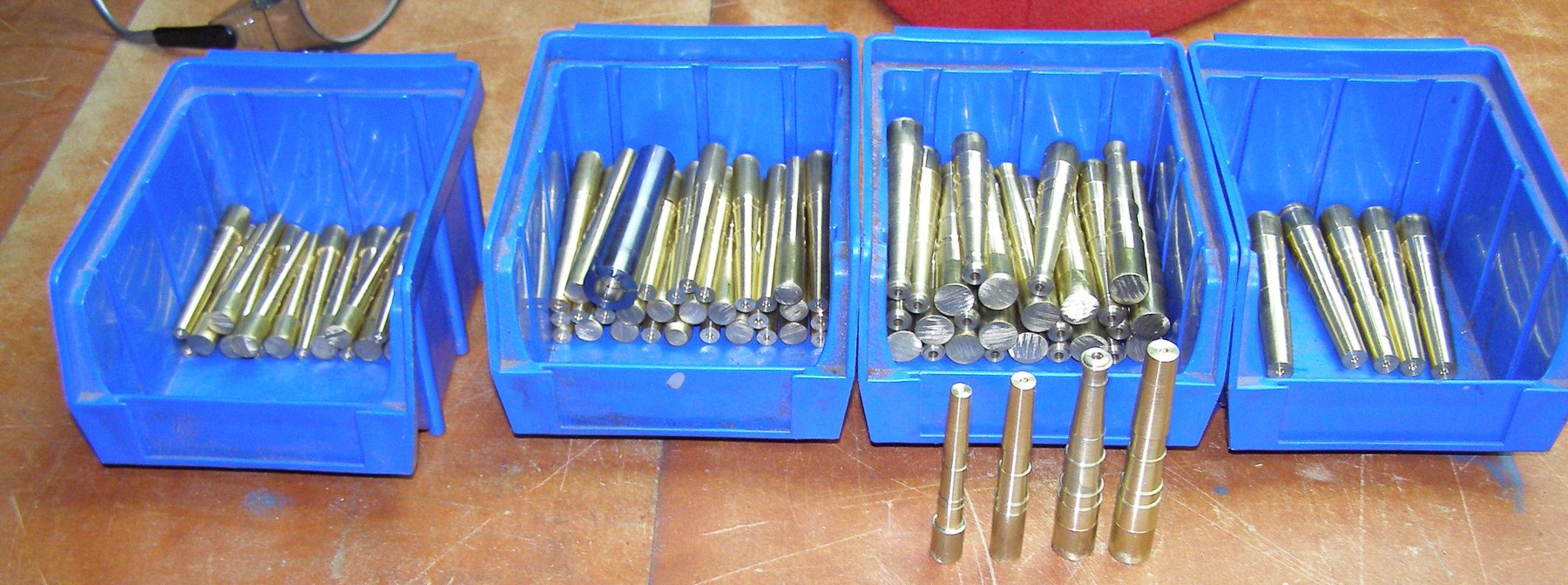
None of the above. The first times I used a duplicator for Unimat. Now I use a taper attachment, a guide to set a precise angle for the taper. I work by steps which is at the end a faster method but collets are required to reposition blanks more precisely Example first deck cannons, same step for each ones, then second step for each one and so on


-
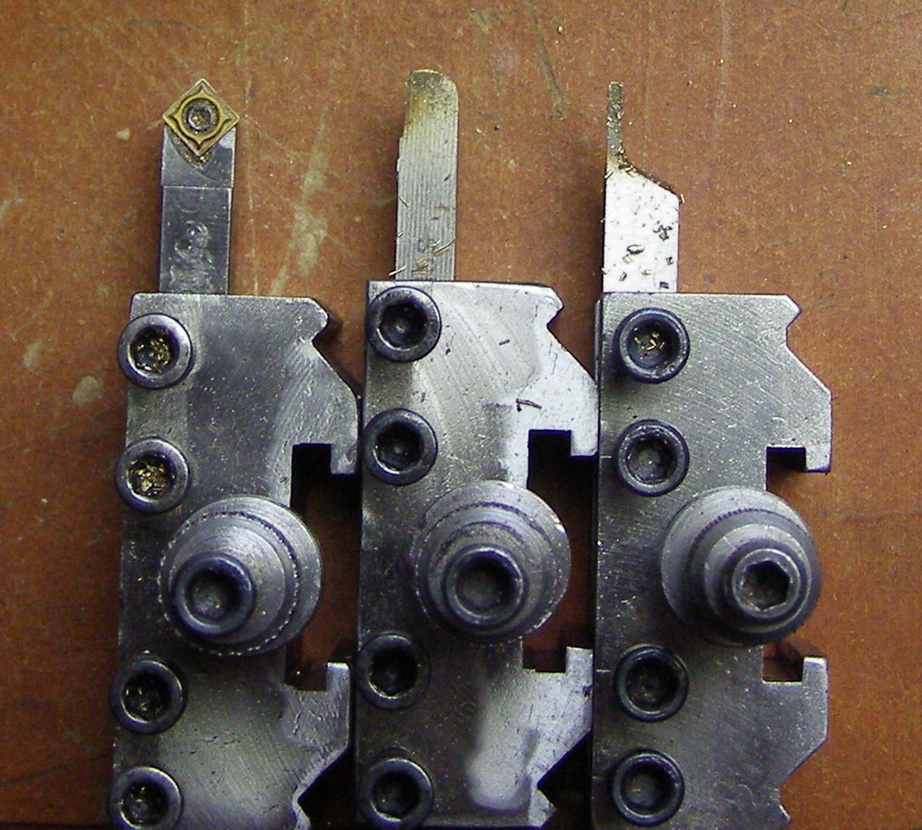
here is the cutters I use

-
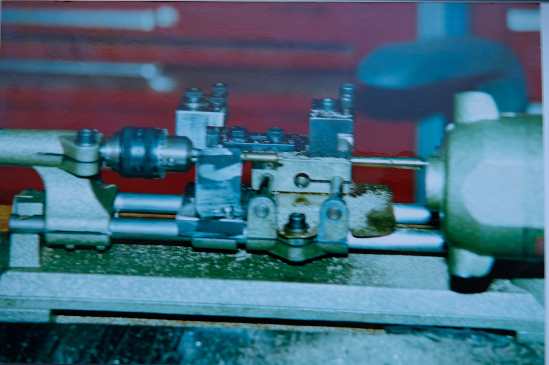
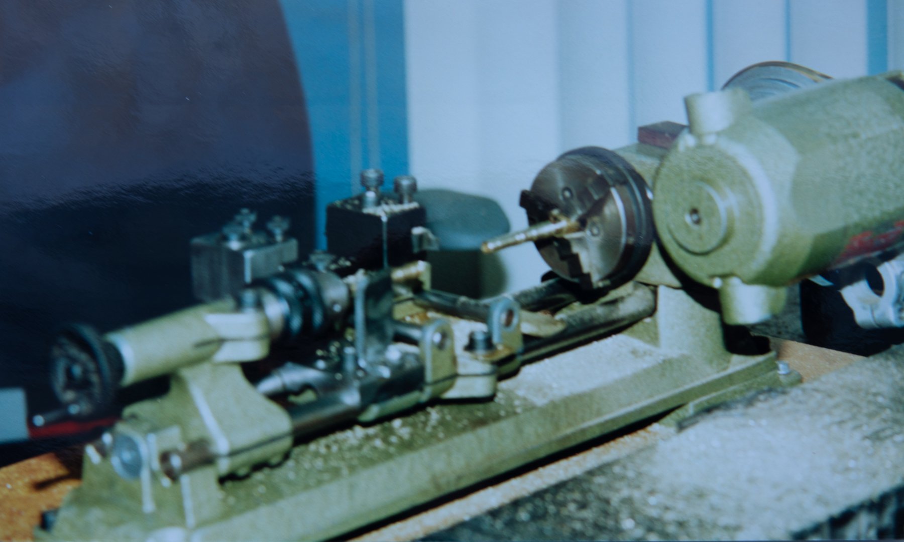
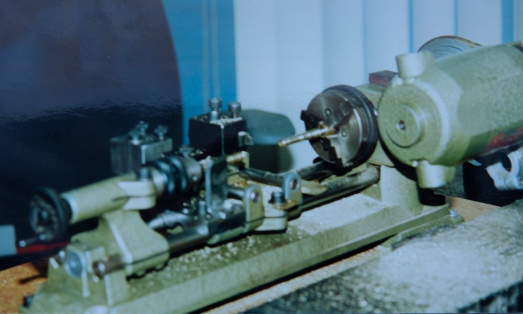
I used another method with Unimat Lathe. The difficulty in taper turning is to set the angle of the taper. This setup has no angles to adjust


-
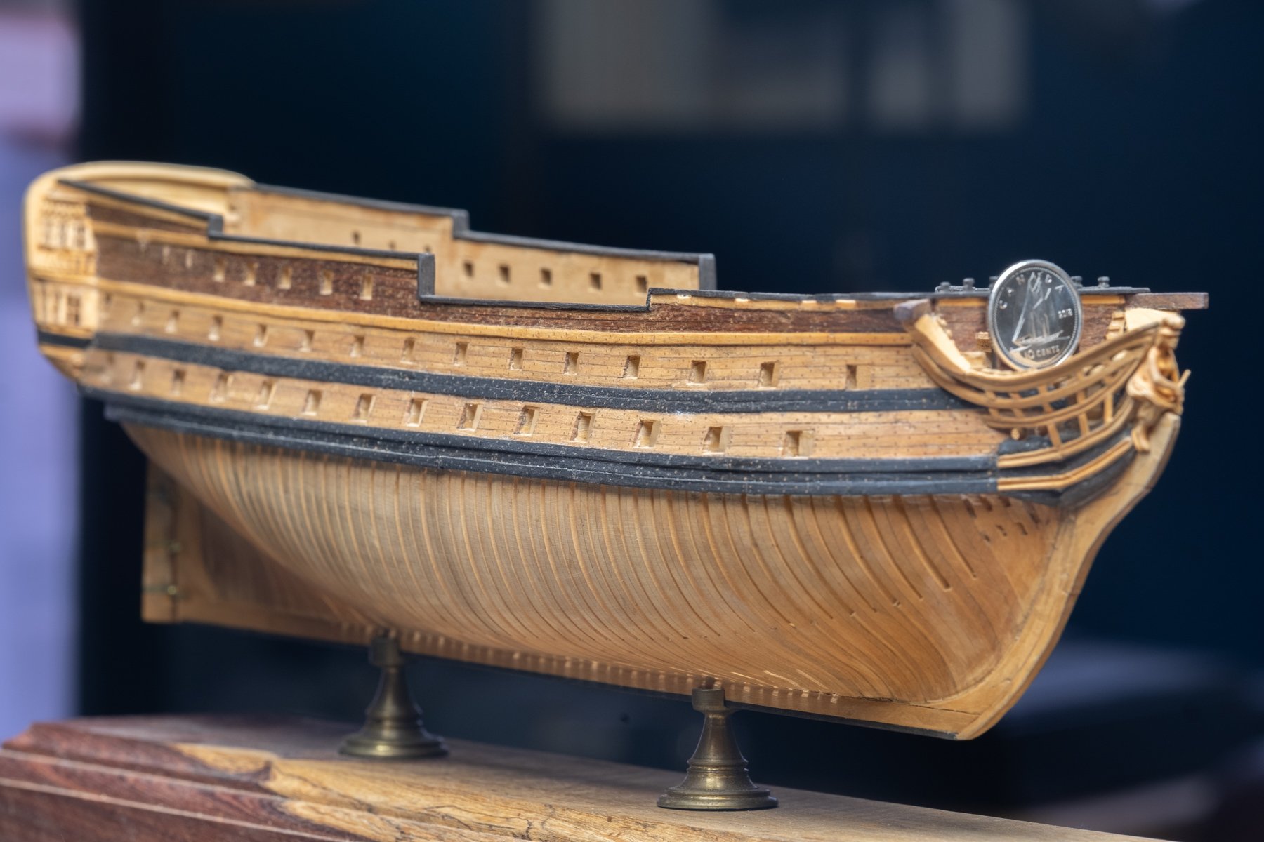
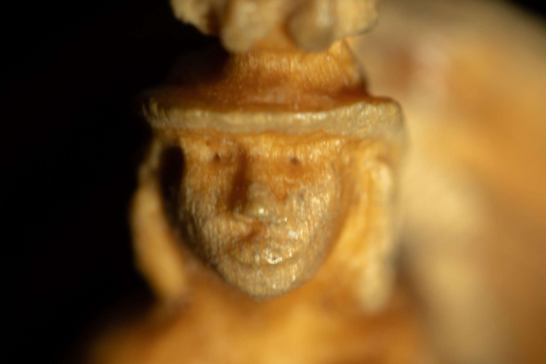
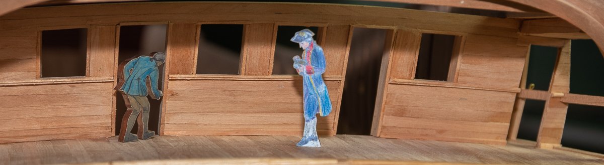
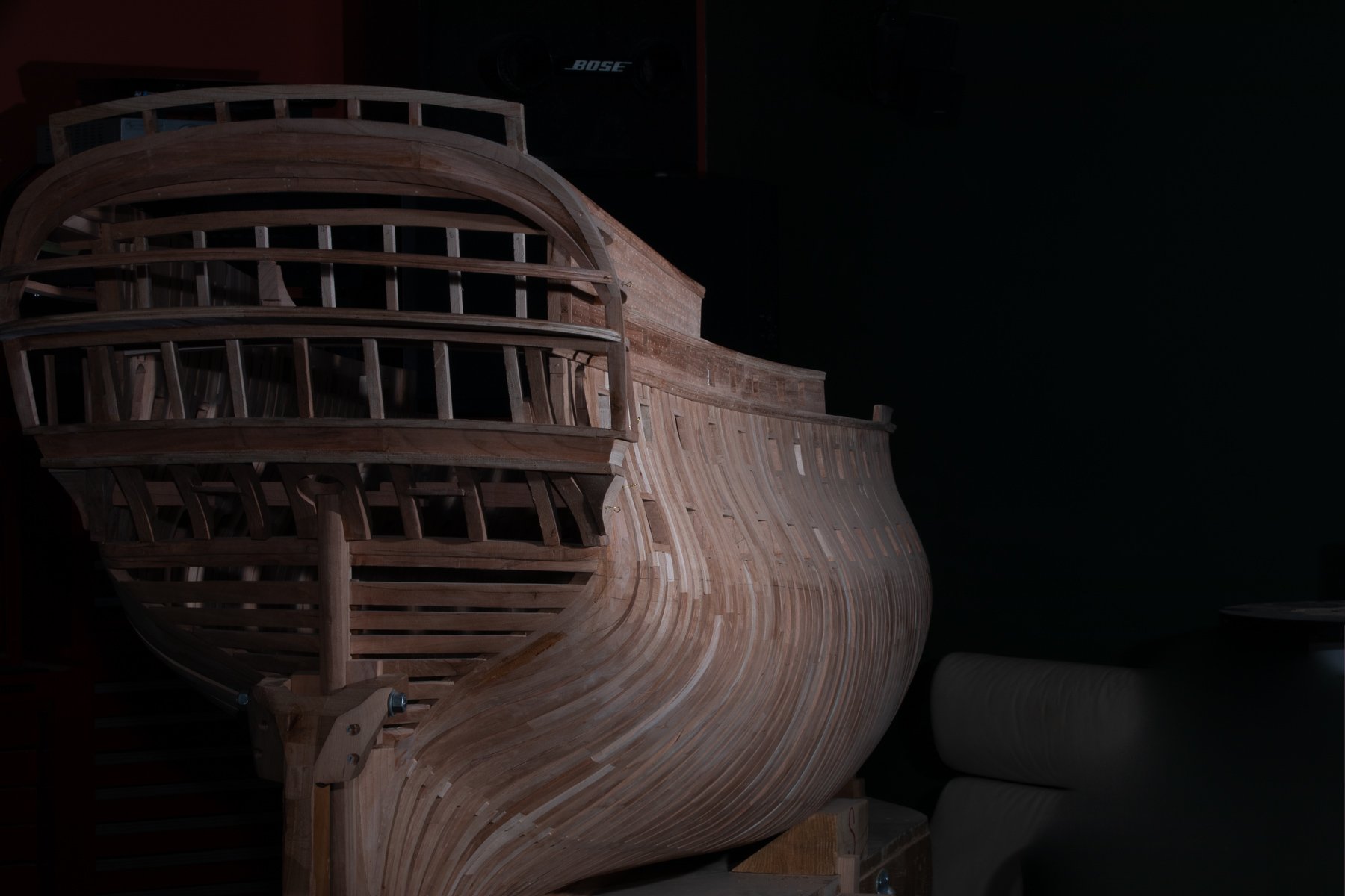
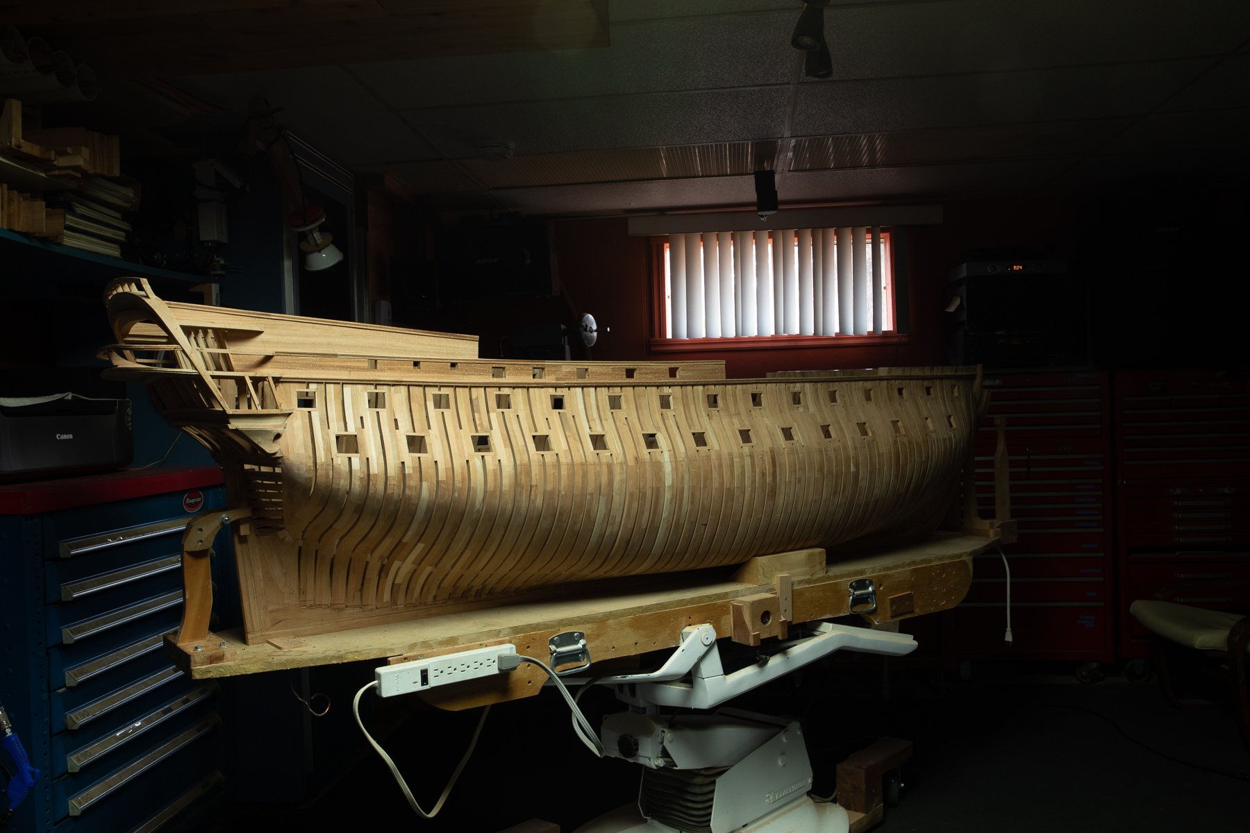
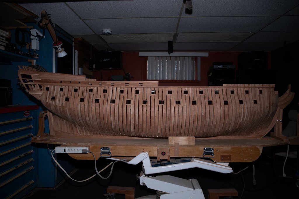
USING A FLASH OR NOT? Last week, a man, in an exhibition, was saying that he was always using a flash in manual mode, never in TTL (true the lens). Many years ago, it was true. Todays flash are much more performing. Here is another common belief : a studio flash is much more performing than a flash on a camera. With the development of the electronic technology; you can buy a flash which fits on the camera hot shoe and it can perform in TTL as good as in manual. This week, I got a new on camera flash and I am very please by his performance. On the last 2 photos, untouched, show the result of this morning test : The first one : with a flash in TTL mode, 100% automatic. The last one : no flash, neon lighting. The color are not as much appealing!

-
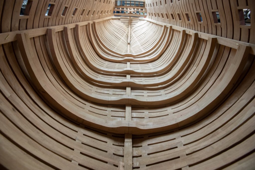
Welcome back Mark, You should build at 1/24 scale! It is a lot easier to do the planking in the curves with 0 stress on the planks, The plank is cut in 3D including the curve, the only drawback: it takes more wood.
-
Partially true; sometimes, the work is done in the head when going to sleep. I do not work many hours daily, but on a regular base . Thank you, everyone, for your likes.
-
Installation of the terrace floor. Only a table is missing for the party.

-
That would be a nice cover page for Lee Valley. I could not do better.
- 968 replies
-
- 8
-

-
- hahn
- oliver cromwell
- (and 1 more)
-
Last night, just before supper, I did a link between desk arm supports and a chair. I had both extremities, just needed the link. I like to build with brass nails, temporary links between 2 wood parts. This allows to see if connection angles are good before gluing everything.