Roger Pellett
-
Posts
4,519 -
Joined
-
Last visited
Content Type
Profiles
Forums
Gallery
Events
Everything posted by Roger Pellett
-
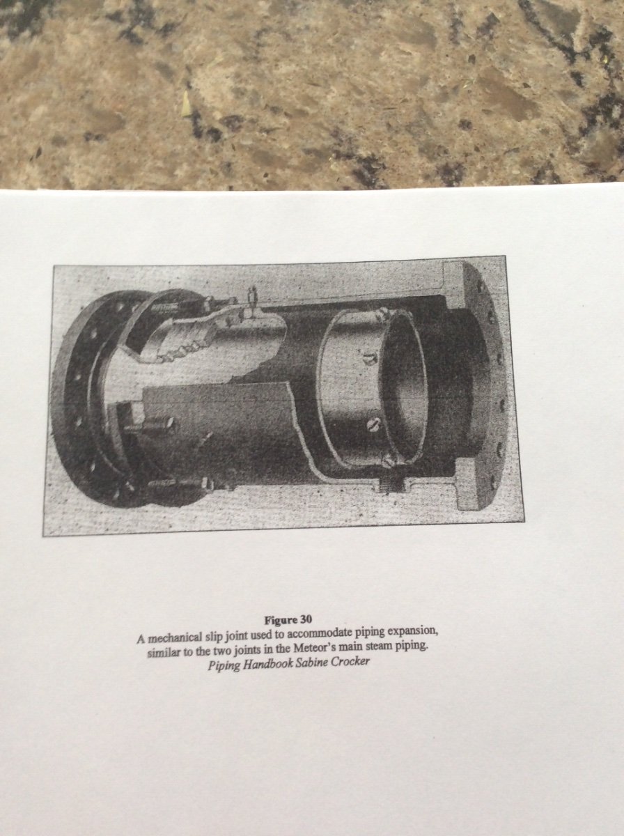
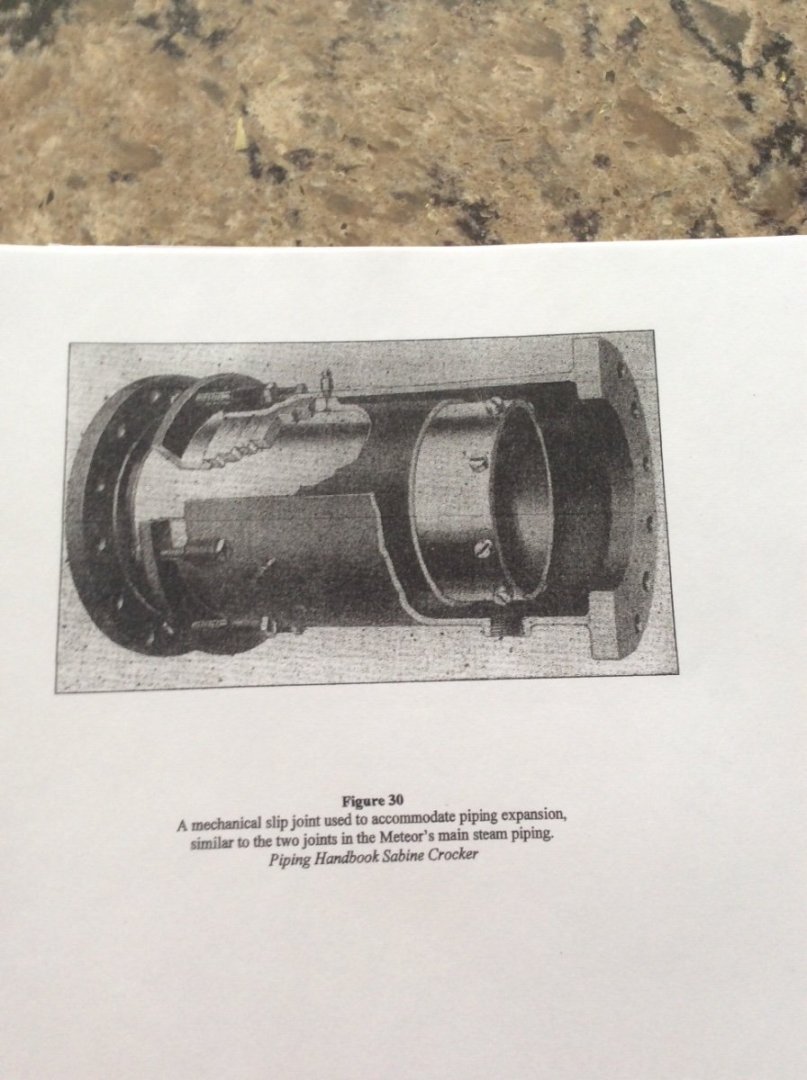
Peerless might not have had expansion loops in her steam piping. The need for expansion loops is dependent on a number of factors; the stiffness of the pipe itself, the steam temperature, the length of the piping runs, and the arrangement of the piping. Changes in direction inherent in delivering steam to the engines add flexibility to the piping. The pipe itself becomes exponentially stiffer as it’s diameter increases. Your piping is small in diameter and since Peerless is a small vessel the piping run is short. Prior to the availability of CAD linked computerized analysis programs, piping system flexibility calculations were very tedious involving trial and error solution of multiple simultaneous linear equations, challenging for most engineers let alone riverbank Steamship constructors SS Meteor built in 1896 is the World’s only surviving Steamship built to a patented Whaleback Design. While her historic significance has been reduced by changes made over her long working life, her Scotch Boiler/ Triple Expansion Steam Engine propulsion plant is a remarkably well preserved example of late Nineteenth Century Marine Engineering. Two fire tube boilers delivered saturated steam to the engine at 170psi, typical for the period. The single short, 10in diameter main steam line was fitted with a flanged slip joint expansion fitting that eliminated the need for an expansion loop. This would have been a patented fitting supplied by an outside vendor to the shipyard. Fittings like this would have been available to Peerless’s builders as well. Photo below: Roger
- 266 replies
-
- 12
-

-
For small wooden parts like this you might find a harder wood easier to work with. As wooden parts get smaller, it can become harder for soft woods to hold their shape. Using a harder close grained wood can make it easier to make the small cuts that result in nicely shaped parts. To work these harder woods it is not necessary to have access to a fully equipped workshop as there are many commonly available items made of woods that could be used as better raw materials than Basswood for carving these small parts. For example: Tongue Depressors. To get a symmetrical shaped set of jaws glue two pieces together and carve them. When you are happy with the result dunk them in the proper solvent to separate them. Roger
-
Not a suggestion that you need to paint your piping, just to add to the discussion about insulating piping. Context, or local color? In addition to the reasons discussed already, poorly insulated steam lines can be very dangerous. There have been a number of violent steam explosions in buried underground district steam heating lines. The mechanism is something like this: An insulation failure allows water (or wet air) to come in contact with the surface of the pipe causing a cold spot. Steam begins to condense at this spot. The slug of water is propelled at high speed until it hits the next change in direction. This Water Hammer can rupture the pipe, releasing the contained energy of the steam. Roger
-
It would appear that this thing is right up there with the Loom a Line.
-
A very nice little model! It’s obvious that your skills and confidence are rapidly improving. Well done! Roger
-
I do not build working models. The ones that I build spend their lives in glass cases. FreekS’ post appears to provide you with good information about the small electric motors involved in model ship propulsion. Screw propellers work by taking advantage of Newton’s Third Law; Action- Equal and opposite reaction. In this case the action is a slug of fluid pushed aft by the propeller. The reaction is the equal and opposite force pushing the ship or aircraft forward. Aircraft propellers turning at high speeds act on a very low density fluid- air. Ship propellers act on a much more dense fluid, water and turn much more slowly, requiring high torque. I agree with FeekS that you will probably need a gear box. Roger
-
You’re probably going to have to make some calculations but I suspect that anything in the 1000’s of RPMs is way too fast. The RPM for the full sized tugboat would be something in the neighborhood of 75-90RPM. You need to consider the whole drive train including the motor’s speed torque curve with the propeller’s geometry and the resistance of the hull at various speeds. It wouldn’t surprise me if that prop stalls the motor. Roger
-
I agree with Bricklayer. Spruce is a great choice for planking your model. Why? Plans directed at model makers often do not space bulkheads close enough. This can make it hard for you to produce a “fair” hull; one without knuckles and flat spots where you don’t want them. Spruce is known for its ability to bend easily in a fair curve. I have a stash that I rip into splines for drawing lines drawings. It is also the lightest of the family of softwoods (those woods cut from coniferous trees.) In addition to differences in the King’s English and American English, lumber can have it’s own nomenclature. If you do plan to use spruce, make sure that you’re buying the real thing. Roger
-
Yeah, no price listed but I suspect that you guys could add a whole Nelsonian fleet of kits for what they’re asking.
-
My completely unscientific understanding of MSW members leads me to believe that a substantial majority have a compelling interest in modeling vessels of the Lord Nelson era Navies.😀 This is particularly true if one adds American War of 1812 ships to the mix. SO!! Here’s your chance! M.S. Rau an antique dealer in New Orleans is advertising in the Wall Street Journal a rediscovered portrait of Admiral Horatio Nelson as a young man. It is supposedly only one of two portraits of him in civilian attire. Just the thing to display over your recently completed HMS Victory. If you have the space to display a fully rigged Victory, this picture w I’ll fit in nicely. Width: 30-3/8”. Height: 39-3/4” Roger
-
Mini Bench Drill Press
Roger Pellett replied to Gregory's topic in Modeling tools and Workshop Equipment
0.7mm=.02755in which my converter rounds up to 1/32”. Small (Real) Jacobs chucks will close to zero. For many of us, this inability to accept very small wire sized drills might be serious limitation. Roger -
Eric, I hope that you don’t mind a friendly suggestion. Your steam lines should be insulated. This is not because of thermal efficiency. Instead it would be required to prevent condensing of steam in the lines. Water is the enemy of the reciprocating steam engine since it is incompressible. The fire tube boiler for your boat would have generated “saturated steam.” That is steam at the temperature applicable to the pressure at which the feed water enters the boiler. As as the steam begins to cool from this temperature as it travels through the piping, it begins to condense and water droplets are formed. This water could build up in the engine cylinder causing damage. I believe that a coat of whitish paint should suffice. As a model railroader you might be interested in this. For several reasons; thermal efficiency as well as that described above, it was desirable to heat the steam to a temperature well above its boiling point. This is called superheat. In the early 1900’s American Railroad Engineers using European Technology began to convert existing steam locomotives and to produce new ones to generate and run on superheated steam. This involved routing the steam after it was generated through very hot exhaust gasses from the boiler. Many of the Railroads maintained their own locomotive design departments to design locomotives specifically adapted to the geography of their particular routes. This attracted many of the best Mechanical Engineers in the USA as well from Europe. There is an excellent book that delves deeply into this topic: American Steam Locomotives, Design and Development 1880-1960 by William L. Withuhn. It is, of course unlikely that your modest steamboat would have been equipped with this sophisticated technology. Roger
-
The W.P. Snyder, preserved at the Ohio River Museum at Marietta, Ohio was a coal burner. Unlike Peerless, though, she was owned by a steel company that used coal in the steelmaking process and possibly owned their own mines as other steel companies did. Therefore, a principal cargo, pushed in barges would have been coal. I believe that her bunkers, were arranged near the bow per. Kurt’s Chaperon arrangement above. Arranged like this coal could be rapidly loaded by gravity at terminals along the River. As a short haul trader, I wonder if Peerless’s fueling arrangements might have been more informal, burning either cord wood or coal as available? In this case, coal could have been wheeled aboard in large burlap sacks with a ready use supply piled in front of the boiler. Roger
-
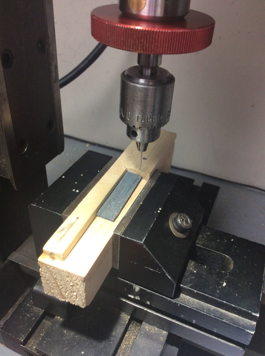
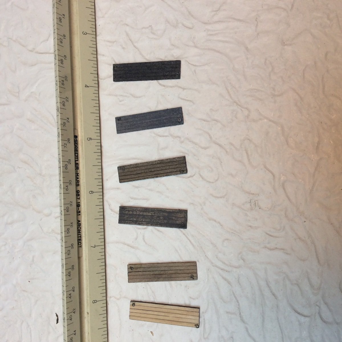
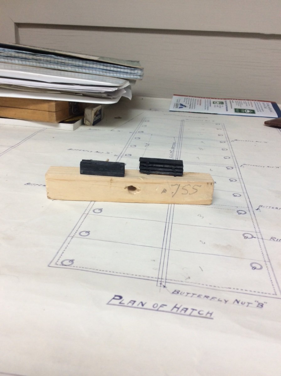
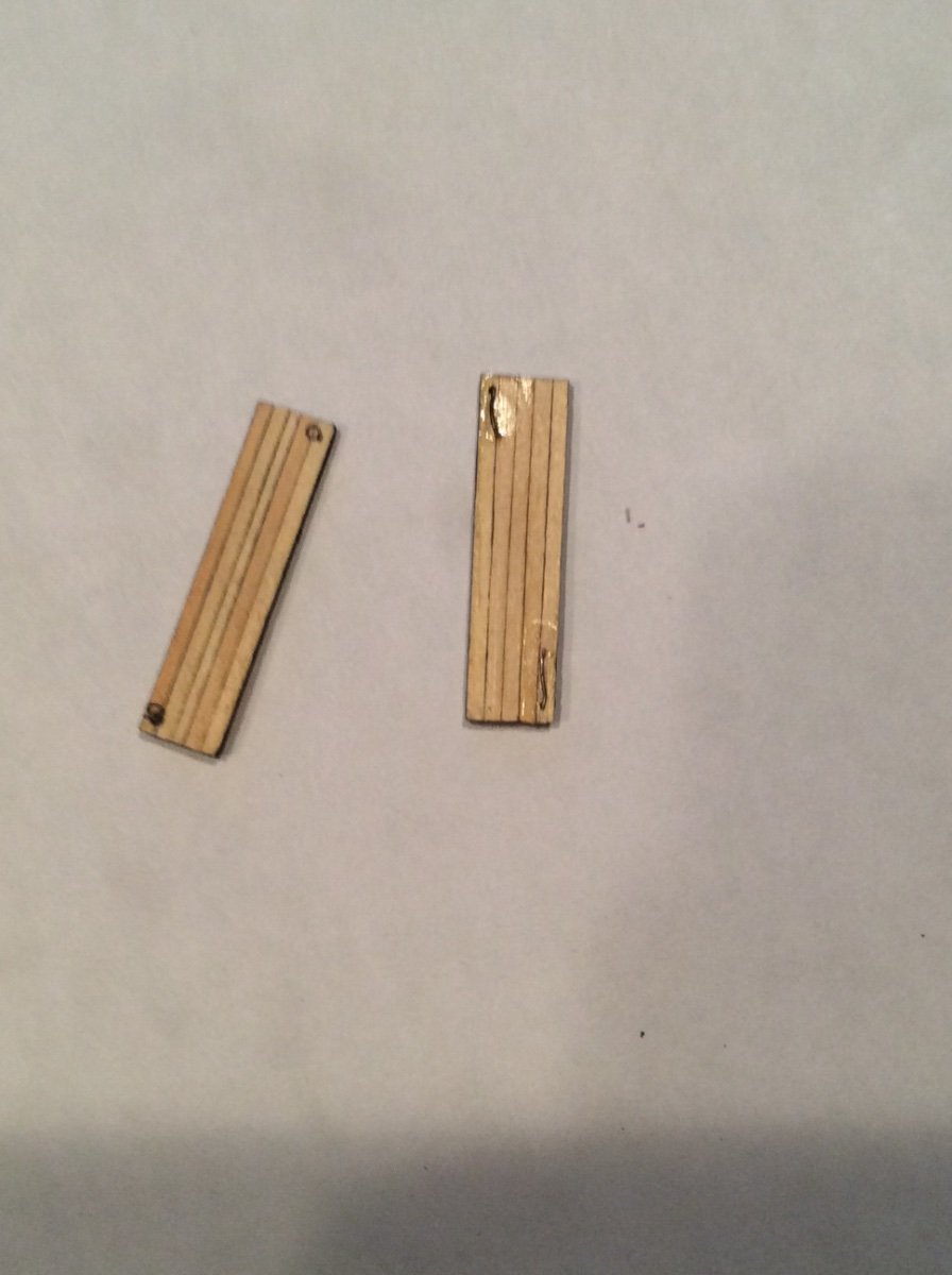
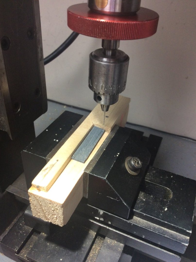
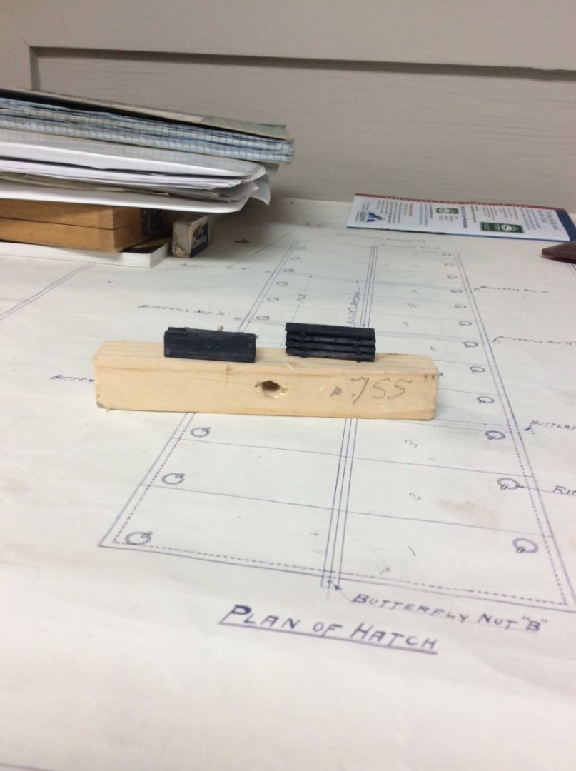
Finishing the hatch covers: Today marks the official end of the 2023 Great Lakes Shipping season. Vessels arriving at the queue for the SOO locks by midnight will be locked through in either direction. After that the locks will close until March 25 isolating Lake Superior from the other lakes. It has been a good season with the twin ports of Duluth, MN and Superior WI shipping 51 Million tons of pelletized iron ore to American and Canadian steel miles. The ports also handled significant quantities of limestone, cement, coal, and grain. The reason for the lakes’ 10 week closure each winter is not ice. Great Lakes vessels can and do navigate in ice. The 10 week closure is required to perform maintenance that has been deferred during the shipping season. Superior, Wisconsin is home to one of three active American drydocks on the lakes. It can dock vessels up to 800ft long. This winter will be busy. Eight vessels are scheduled to lay up in the harbor here. The layup each winter means that Great Lakes ships are and in the past have been well maintained. That, and the fact that they sail in fresh water means that weathering of the model will be minimal. A notable exception is the Noble’s hatch covers. The few photos that I have found of wooden hatch covers of Great Lakes vessels show a checkerboard of different weathered colors that vary from like new wood to black. The first step in finishing the covers was to drill holes in them for the ringbolts. This was done using the sensitive drilling attachment mounted in the Sherline milling column. Another of my simple wooden jigs assured correct location. (First Photo). Adding the two ringbolts to each cover was then just the matter of pushing the tail through the hole, bending it over and securing it with a dab of lacquer based fingernail polish. (Second photo). To finish the covers I mixed up five different grey and black pigments and diluted them with alcohol. For a couple of shades I added some granulated grey and black dry dye pigment to add a gritty texture. (Third photo). The different colored hatch covers will be arranged in a random pattern when they are added to the model. Finally, (Forth Photo) two stacks of hatch covers to be fastened near the ship’s open coal bunker. Roger


-
These semi Diesel engines used to be very popular for applications like commercial fishing boats. They allowed diesel fuel to be used instead of the highly volatile and dangerous gasoline. The glow plugs allowed a lower compression ratio and a lighter engine. The glow plug was initially heater with an external heat source but once the engine started combustion in the cylinders kept them hot. Even though not a true Diesel, Gjoa’s engine is still massive. Roger
-
In its mounted condition, the model’s waterline should be level. If you have the drawing that you used to build the model simply draw a line parallel to the waterline shown on the drawing. Draw lines perpendicular to the line that you just drew and measure the distance to the keel. Buy two pedestals that meet these dimensions. If you don’t have the drawings set the model up temporary supports with the waterline level. Measure up just like you did above. Roger
-
For the Beginner Modeler
Roger Pellett replied to kgstakes's topic in Modeling tools and Workshop Equipment
Equipping a workshop is entirely dependent on the type of modelmaking that you intend to pursue. I will agree that assembling a POB kit can be accomplished with a minimal collection of hand tools. That’s one reason why people buy kits. Moving into scratch building, POB, or even some POF models of classic age of sail vessels can also be built with hand tools if you are willing to use purchased metal fittings. Modeling iron and steel hulled vessels is a different situation, especially if you intend to meet 1a criteria (only chain and cordage purchased). Here you can’t have enough tools! Our modeling world is by no means limited to Eighteenth Century Sailing Ships. Roger -
Roter Löwe 1597 by Ondras71
Roger Pellett replied to Ondras71's topic in - Build logs for subjects built 1501 - 1750
An old naval expression says it all, “A ship is judged by the condition of her boats”. Yours is spectacular. Roger -
Wooden ships “work.” As the ship travels through waves, the uneven buoyancy causes the hull to flex. With conventionally framed construction the frames made no contribution to to the longitudinal strength of the hull. In the Nineteenth Century the use of diagonal iron strapping was an attempt to add longitudinal strength to large hills but of course this was three hundred years or so prior to Mary Rose. As ships aged these longitudinal bending stresses affected planking fasteners allowing individual planks to slide relative to each other, working the caulking loose. The repair would have been to caulk the seam and to nail the batten atop. This problem existed to some degree into modern times until advanced adhesives allowed monocoque construction of wooden hulls. Roger
-
Wives are right about most things but not everything. People who do not build ship models cannot understand the drive that keeps us moving forward to create a masterpiece. Unfortunately, none of us have unlimited years to spend doing this so it behaves us to spend the time that we do have wisely. There is little point in working on a model that does not inspire you just so that you can cross it off of your list. If clipper ships in general and Flying Fish in particular is your interest, don’t give up. You’ll surprise yourself! Roger
-
Battens: I seem to remember that she was quite old when she sunk. The battens might have been added later in life to keep caulking in place. Roger
-
Since you are glassing inboard and outboard I assume that this will be a working (RC) Model. Correct? Roger
-
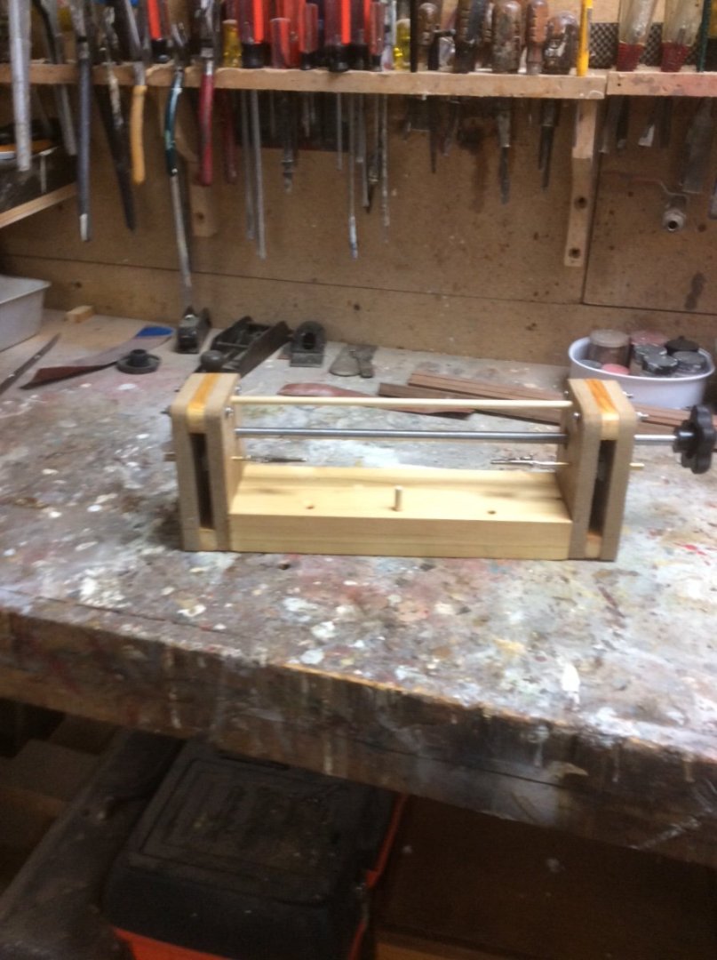
I second Wefalck’s suggestion. The key to one of these otherwise simple machines is a set of gears. Since the machine works at very slow speeds and carries very little load, plastic gears work just fine. These are readily available from online sources like Amazon. The photo below shows a serving machine that I built several years ago using ordinary workshop equipment and scrap materials in my shop. The gears are inside of the two vertical slots. There are no bearings, just holes in the four vertical MDF pieces. The shaft is steel but you could use Aluminum or in a pinch even plastic. The clips to hold the line being served are Alligator clips widely used in the electrical/electronics industry. Roger
-
Welcome to MSW. Not just from Minnesota but Duluth!! Roger
-
I too enjoy browsing stores like Michaels to find things that can be adapted for building models. Unfortunately, a lot of the “brass” nails, pins and such turn out to be brass plated steel. Roger