Roger Pellett
-
Posts
4,519 -
Joined
-
Last visited
Content Type
Profiles
Forums
Gallery
Events
Everything posted by Roger Pellett
-
MDF is just a substrate, a blank canvas. It can be finished with a variety of finishes. If the finish is tasteful and well done it will look fine. For example, MSW member Druxey is a master at applying faux marble and wood burl finishes to ordinary base materials. Unfortunately I can’t come close to matching his artistic skills. A caution- MDF is a wood fiber product and can and will warp from changes in ambient moisture. It is therefore necessary to balance the two opposing sides of the baseboard. A while ago, I glued a piece of veneer to one surface while leaving the other exposed. It warped like a banana. So, if you paint or otherwise finish one surface it’s necessary to likewise treat the other. Roger
-
Since your model was purchased in 1954, it would be of the original Bluenose, not Bluenose II. Bluenose II was not launched until 1964.
-
OcCre HMS Victory Limited edition
Roger Pellett replied to modeller_masa's topic in Wood ship model kits
$1500+ buys a lot of tools and books! -
Back in the day, pine was the preferred material for solid hull ship models. IMHO it is an under rated ship modeling material, much better than most kit materials, and better than Basswood. American lumberyard softwood is usually SPF- Spruce, pine, Fir. It pays to sort through the pile to find the pine. Often it is not necessary for ship modeling purposes to buy the high grade select pine. Areas of a plank with knots can be discarded leaving plenty of straight grained material for our purposes. Roger
-
Great pictures of an interesting vessel. The engine appears to be a compound version of a Western Rivers steamboat engine. Western Rivers defined as the Ohio, Mississippi, Missouri watershed. Most of these engines were single expansion; steam from the boiler was expanded in the cylinder and exhausted to the atmosphere. The heat energy in the steam at atmospheric pressure was therefore lost. This engine has a second larger cylinder arranged in tandem with the high pressure (HP)cylinder. After being expanded in the HP cylinder the steam was piped into the second cylinder where it expanded further. By expanding the steam sequentially in two separate cylinders they, the cylinders, remained at a more constant temperature. It is also likely that the pipe in the foreground from the LP cylinder going through the deck leads to a condenser below. This used river water to condense the steam, recovering the heat energy remaining in the steam from 212F to the temperature of the river water. Roger
-
The pear wood stash is mine not Allan’s. It was cut back in the 1970’s by someone who was building a house near Marietta, Ohio. I had it sawn into slabs at a backwoods sawmill. It sat around indoors and outdoors until a few years ago when I flattened it on my jointer, planed it and sawed it into billets. Roger
-
Allen, I suspect that most are returning to the Twin Cities about 150 miles south of Duluth where we live. We have a Friday lunch group during the summer we get about 8 guys. Last Friday there were three of us, the rest headed to warmer climes. Leaves are all gone. It’s a long story, but my wife and I have decided to forgo our March visit to Marco Island this winter. We had been going every year since 2004.😒 Roger
-
I don’t know what Dremel currently offers but the classic “Dremel Tool” turns too fast to be a good drilling tool. If Dremel offers a variable speed tool that maintains torque through its RPM range that would be something to consider. I believe that MicroMark offers a true hand held miniature drill. Roger.
-
Allan, I have two planks of real boxwood bought back in the 1970’s. I also have a stash of pear locally cut when I lived in Ohio. Every so often I consider putting my current project on hold to build something else that makes use of this beautiful wood. Right now I’m plodding along making 144 1/16” OD hatch cover ring bolts. 80 done and 64 left to do! I have a routine Dr Appt in two weeks. If he tells me to get my affairs in order because I have some incurable disease the first order of business will be to decide who gets the boxwood.😆 Bid Creek Dad, Everyone has his own opinion. That’s mine! Roger
-
I personally feel that unpainted models are overdone. I agree that wood left naturally is appropriate for true Dockyard style models with exposed framing built from the big three woods- boxwood, pear, holly. On the other hand there is something about unpainted POB kit models that makes them look like either “gift shop specials” or toys. My models are long term projects. They involve years of dreaming, mental construction and planning before I pick up a tool. Part of this involves an artistic vision involving display of the model. This includes selection of materials for baseboard rd and case. All but one of my models are painted, except where the actual component on the real vessel was finished bright. Roger.
-
By the time that these ships were built Naval Architects realized that the large keels built into wooden ships were no longer needed as structural members. The major strength members in a steel hulled ship that act as a keel to withstand longitudinal bending loads are the inner bottom structure and bottom shell plating. The primary function of the structure in way of what was formerly the keel is to withstand the concentrated loads encountered during dry docking. Roger
-
Hi Valeriy, I always look forward to your posts as they show that you are able to still lead a somewhat normal life during these difficult times. It’s also great to see another steam merchant vessel under construction. I build my models as two half models too. This method ensures an accurate hull. Roger
-
Shot Garlands
Roger Pellett replied to tmj's topic in Discussion for a Ship's Deck Furniture, Guns, boats and other Fittings
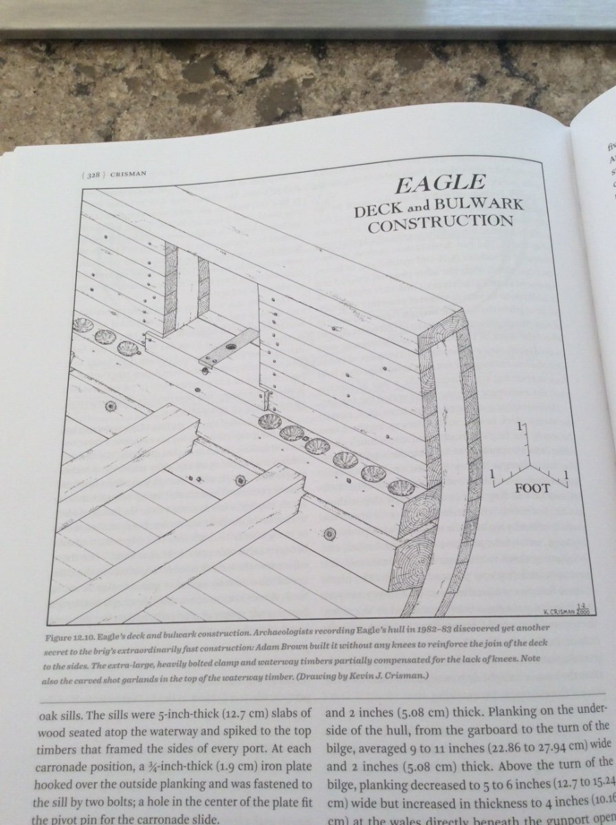
Eagle, the vessel posted in the drawing above, was quickly built in an area with unlimited timber supplies and she was considered to be expendable. Her construction, therefore, was not in accordance with that required for building major additions to the Navy’s saltwater fleet. If you look at the drawing, you will see that the deck beams were sandwiched between her deck clamp and a waterway; both massive timbers. This eliminated the need to fit knees to tie the deck beams into the side structure. The large, rectangular waterway provided plenty of “meat” for cutting the holes for shot storage. Your Trial was built with the usual knees to tie things together hence her much smaller sculpted waterways. I doubt if this strength member would have been cut to store shot. Roger -
Shot Garlands
Roger Pellett replied to tmj's topic in Discussion for a Ship's Deck Furniture, Guns, boats and other Fittings
This photo shows the bulwark and shot storage holes for the Brig Eagle built in 1814 to defend Lake Champlain from British Invasion. The drawing was made from the wreck evaluated by archeologists. Eagle was a late addition to the American Fleet and built in a matter of weeks not months or years so there were many shortcuts taken in her construction. This is, therefore, not suggested to be a typical arrangement Roger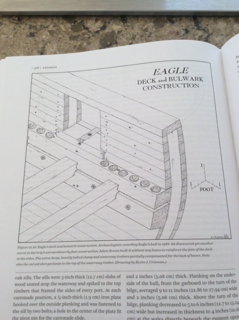
-
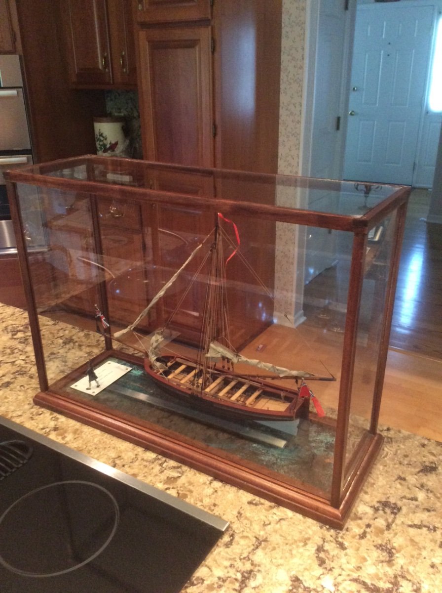
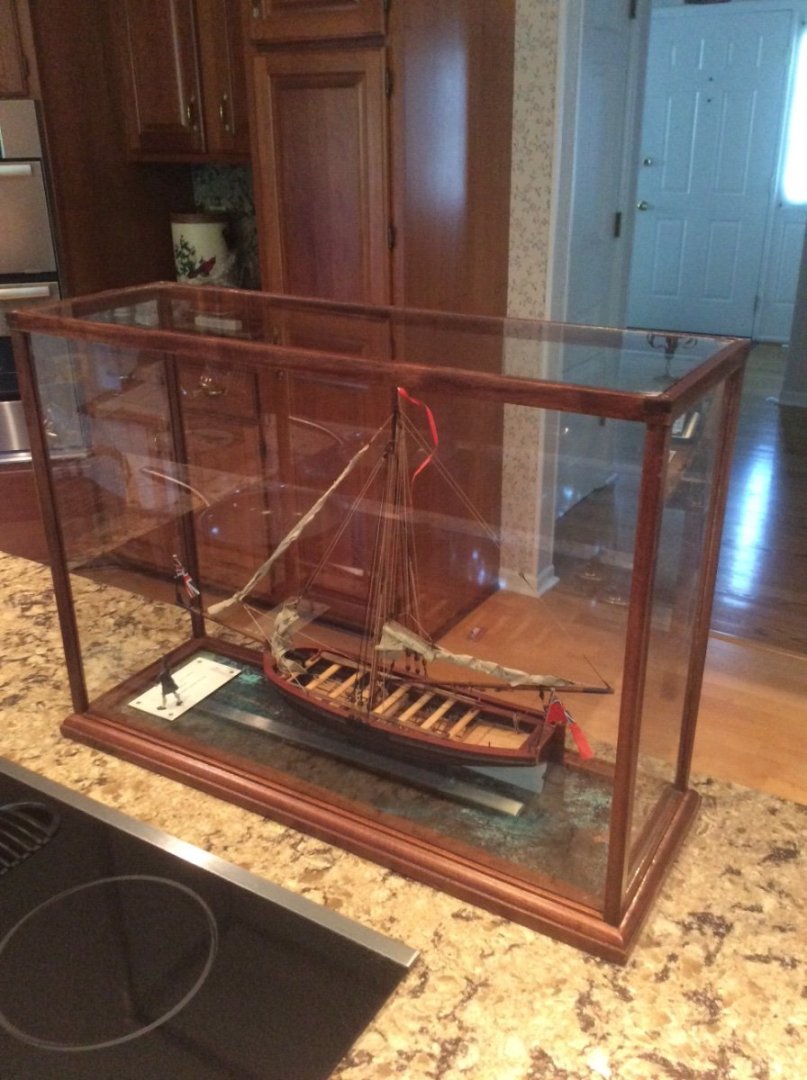
Like many on the forum, I have been attempting to build ship models since I was a small child. Way longer than I care to admit to! The first model that was nice enough to deserve a case was a “Yellow Box” Model Shipways Harriet Lane received as a gift in the mid-1960’s. The case was a sad affair made from plexi-glass glued to a Walnut base that eventually warped. I eventually developed a system for making wood framed glass cases. These are neat, and rugged but not artistic works of cabinetry like some posted on the forum. Some are old enough (35-40 years) that I was unaware of problems from off-gassing and didn’t consciously worry about ventilation. Some of the older cases feature veneered baseboards glued to a plywood substrate with rubber based contact cement. Somehow all of this has survived the test of time! While I am pleased with my models and cases I’m not to worried about longevity once I’m gone. My daughter has limited space in a New York Apartment and my daughter-in-law is fussy about her decor. The patined copper was inspired be a similar product sold by a commercial veneer distributor. I had a sheet of .005in copper surplus from a project, and the chemicals are not exotic. The effect was far better than I could have simulated with paint. I bought a plastic tub with a lid. The towel soaked with Ammonia and vinegar was spread out in the bottom of the tub. The copper was tacked to a homemade wood frame and suspended over but not in contact with the towel. Salt was sprinkled into the copper. The tub was covered with a snap on lid and allowed to sit for 3-4 days. After it comes out of the tub the copper needs to be throughly rinsed. The copper should be cleaned to remove grease, oil, corrosion before being exposed to the chemicals. Specialty gunsmith supply houses; Brownells, Herters, Cavella, etc. can be good sources for case finishing materials. Some of the woods sold as Mahogany are pretty poor stuff and that’s probably what you got. As mahogany like teak, is associated with classic yachts and fine furniture I suspect that most ship modelers have been faced with trying to finish this faux Mahogany. You should be able to find Wood Filler at local paint stores. This is NOT the stuff kit builders use to try to fill in planking mistakes. It comes in quart cans and is something called Fullers Earth mixed with linseed oil. It can be mixed with your choice of oil based wood stains or you can mix it with oil based artist colors (the kind that come in tubes) to create your own. Paint it on, let it soak in, and wipe it off. Roger
-
The case is native American Black Walnut. Where you live it should be easy to find. The stain is a “French Red” gunstock stain. If you decide on the patina’ed copper, I saturated a towel with the chemicals and suspended the copper sheet near but not touching the towel; all in a covered plastic tub. Roger
-
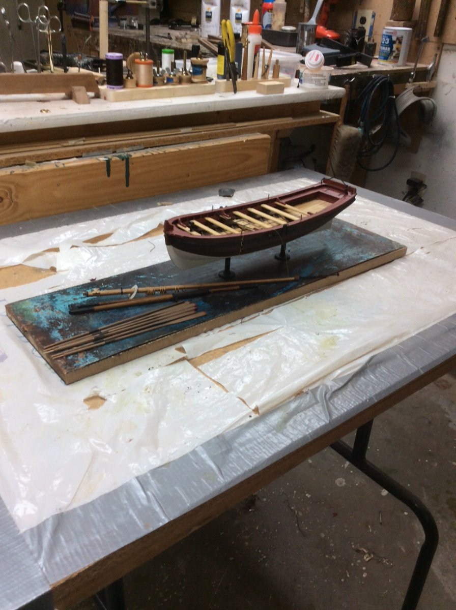
Here’s an idea that I thought worked out well. It is intended to give a impression of the blue green of water. It is a sheet of copper that I treated with vinegar, ammonia, and salt, then sealed by spraying it with Matt varnish. Same effect as Jaager’s sea green/ blue marble base. I treated the turned brass supports this same way. The stripe next to the hull is a light reflection. Roger

-
Shot Garlands
Roger Pellett replied to tmj's topic in Discussion for a Ship's Deck Furniture, Guns, boats and other Fittings
Wrecks of vessels that fought on the American Lakes during the War of 1812 had shot stored in the scooped out holes that you have in mind. Sometimes scooped into the waterways. Roger -
Well done, Dan! Roger
-
Model plywood is widely available. Stores like Michaels carry it. It comes in “nominal” fractional thicknesses, from 1/64” to 1/8”. Nominal means that it is actually metric thicknesses that are close to fractions. I believe that there are two grades; the Craft grade material that you are likely to find locally and a higher grade intended for model aircraft and available from specialty RC model aircraft suppliers. If you use it for the applications that I am suggesting the Craft Grade Material is fine. I suggest that you do need one piece of high class material; the piece for the keel. Many of the kit build logs report warped keels that require a lot of effort and frustration to correct. You can find 1/8” Baltic Birch ply at on line woodworking sources. Try Woodcraft Supply. I personally would not suggest using any sort of plywood for frames. Plywood is great for it’s intended use; covering flat or developable surfaces, but it’s Achilles heel is its cut edge. If you need to use any kind of fastener, permanent or temporary, driven into the edge you can separate the laminations. Styrene, that’s the dark side😆! Roger
-
Tools: It is possible to cut the keel and bulkheads with an inexpensive coping saw. If you plan to go this route, buy the saw, a selection of blades and practice. A powered scroll saw certainly makes things easier. Wood: with scratch building it’s a good idea to develop a building plan before you start. If I were building this I would build it upside down with the tops of the bulkheads attached to the building board. I would extend the bulkheads to be cut off after the hull is planked. Plywood construction requires “developable shapes” as the plywood does not like to bend in more than one dimension. So to accurately reproduce the shape you might have to plank the hull. There is, of course, a “chine log” that defines the chine and provides the landing along the chine for both the bottom and side planking. Diagonal planking would be an easy way to plank the bottom and would probably replicate actual practice. I would not use either plywood or MDF for the bulkheads. I would buy ordinary 1in pine at your local lumberyard/ home improvement store; not spruce or fir. I would Saw it into 1/16” thick strips and use it to build two layered pentagonal shapes for each bulkhead. Stagger the joints. Then use your poster board bulkheads to draw the finished shape on to each and cut it out. The center (keel) piece can be made from thin plywood. See if you can find 1/8” Baltic Birch. The Bottom can be diagonally planked with two layers of craft plywood cut into narrow strips. For the side planking I would cut more of your pine into thin planking strips. Roger
-
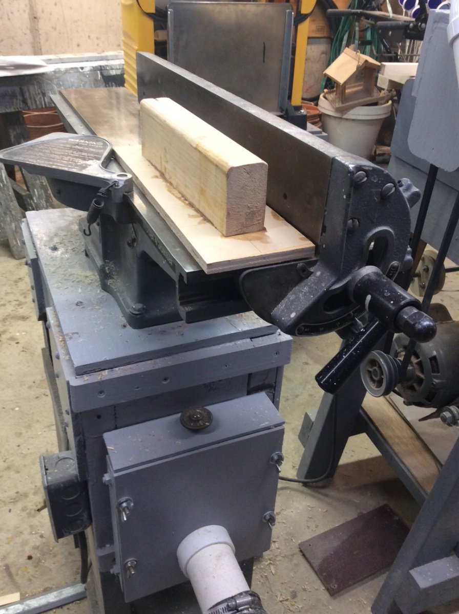
Thanks all! I’m fortunate to have enough space to have two workshops; one dedicated to relatively clean close work and one immediately next to it for cutting and machining lumber with full sized woodworking equipment. This second shop also shares space with gardening tools. The jointer is a wonderful precise woodworking tool. It is close to 45 years old, built when machined cast iron, and external motors with v belts were the standard. 4in (approx 100mm) is enough capacity for my needs. Roger
-
You are a victim of Kit Manufacturer Marketing- using using drawings of a vessel unknown to the public or inventing plans from scratch and then marketing the kit as building a famous ship. Howard Chapelle covers Bermuda built Schooners in several of his books. In particular there is a lovely three masted Schooner from the very early 1800’s named Flying Fish. This vessel was probably built on the Chesapeake Bay or in the Caribbean. Bought by the Royal Navy, her lines were recorded and used to build several duplicates in Bermuda. She would make an interesting and handsome model. Roger
-
Pin Vise vs. Hand Vise?
Roger Pellett replied to Balclutha75's topic in Modeling tools and Workshop Equipment
It would seem that there are two types of pin vices; ones like the Trumpeter tool shown above intended for hand drilling and those intended for more general use as the Starrett or Moody four tool sets. Wherever possible I try to machine drill holes and these pin vices can be used to hold very small drills. The pin Vice with its drill can then be chucked in my Sherline sensitive drilling attachment. Wherever possible, I try to reduce the number of moving parts when working. I therefore do not find hand vices to be particularly useful. My shop is equipped with several bench vices and I use these whenever possible. If I were just beginning to outfit a model building shop my first tool would be a good bench vice. Roger -
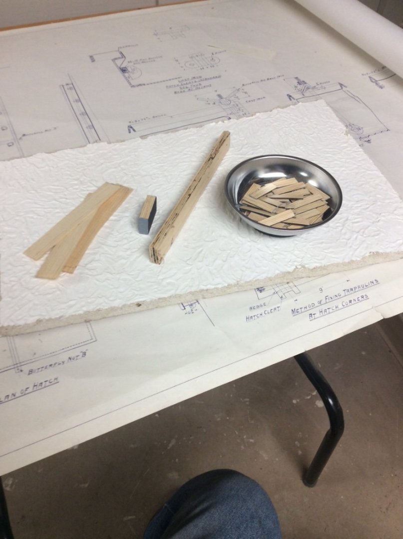
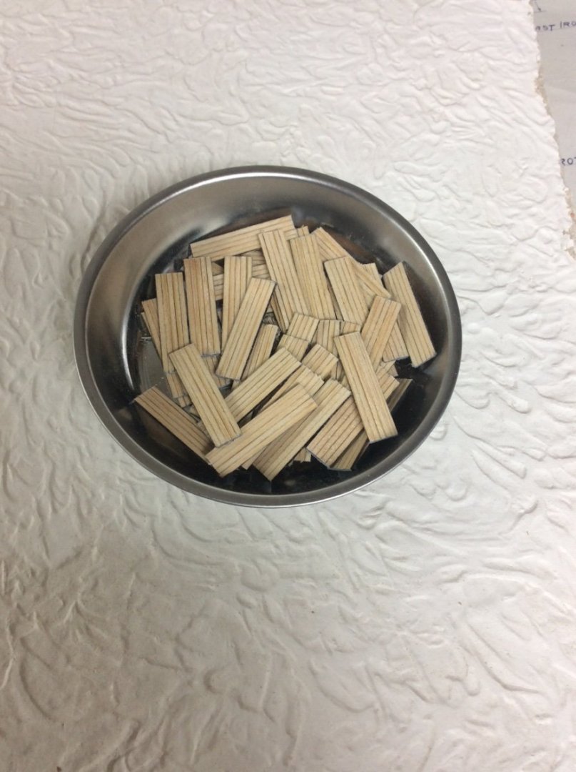
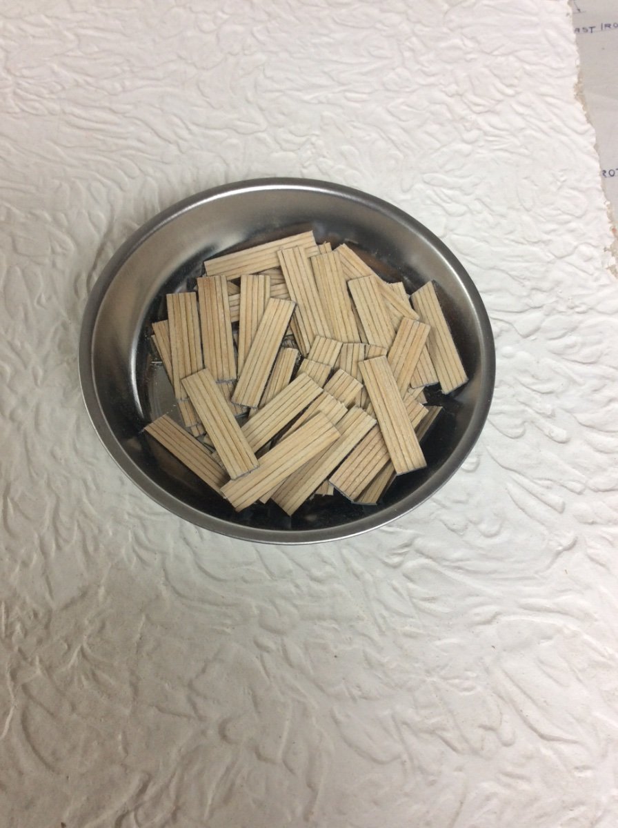
Hatch Covers II Each hatch was covered by 12 wooden covers. The covers, each weighing about 150# were handled by the deckhands; two men per hatch. This was a backbreaking job that had to be performed four times for each usually short round trip voyage. The covers were each 9ft long x 30in wide and were made from 2in x 6in white pine lumber (I assumed that these are actual dimensions and not nominal as is the case today). I had originally intended to make the 12 covers per hatch as one piece using 1/32in thick craft plywood, but recently decided to model each cover separately with individual planks. After considering several options I arrived at the following system: Using some nice 1” nominal clear pine from the offcut bin at the local Menards store, I ripped a number of 1/16in pieces (6in to scale) These had to be accurate within a few .001” as 60 1/16” wide planks make the covers to close each hatch. If each plank were to be .010” too wide, the cumulative error would be 0.60”. I, therefore, glued the saw cut planks to a flat board and used my jointer to remove the few thousands necessary. I then glued the .060” thick strips into stacks, each stack 5 strips high. For glue, I used ordinary PVA glue colored with burnt umber acrylic artist color. I used several large C clamps to get the clamping pressure necessary to get tight glue lines between layers in the stack. Each stack was then tried up to ensure straight parallel edges. Each stack was then cut into 1-1/4” blocks; the width of the hatch coamings. Surfaces that would represent edges of the finished covers were then painted. The Byrnes Saw was then set up with the NRG thin rip guide and the and .030” thick hatch covers were sliced off each block. Yes, the hatch covers are .01” thicker than scale but is is not apparent. Photo: