
Kenchington
-
Posts
758 -
Joined
-
Last visited
2 Followers


About Kenchington

Recent Profile Visitors
2,214 profile views


-
 Canute reacted to a post in a topic:
Kolderstok Ship Models: Dufken, Batavia, de Zeven Provincien
Canute reacted to a post in a topic:
Kolderstok Ship Models: Dufken, Batavia, de Zeven Provincien
-
Kenchington reacted to a post in a topic:
Bateau de Lanvéoc by JacquesCousteau - Scale 1:32 - From Ancre Plans
-
robert952 reacted to a post in a topic:
Norwegian Sailing Pram by DocTom - Model Shipways - 1:12
-
Doreltomin reacted to a post in a topic:
Mary Rose 1511 — the epitome of the Northern tradition
-
 A really, really nice achievement of a very tricky step! Trevor
 -
 Kenchington reacted to a post in a topic:
Norwegian Sailing Pram by DocTom - Model Shipways - 1:12
Kenchington reacted to a post in a topic:
Norwegian Sailing Pram by DocTom - Model Shipways - 1:12
-
DocTom reacted to a post in a topic:
Norwegian Sailing Pram by DocTom - Model Shipways - 1:12
-
robert952 reacted to a post in a topic:
Muscongus Bay Lobster Smack by JacquesCousteau - Model Shipways - 1:32 - Rescaled and Modified
-
Keith Black reacted to a post in a topic:
Muscongus Bay Lobster Smack by JacquesCousteau - Model Shipways - 1:32 - Rescaled and Modified
-
 JacquesCousteau reacted to a post in a topic:
Muscongus Bay Lobster Smack by JacquesCousteau - Model Shipways - 1:32 - Rescaled and Modified
JacquesCousteau reacted to a post in a topic:
Muscongus Bay Lobster Smack by JacquesCousteau - Model Shipways - 1:32 - Rescaled and Modified
-
Paul Le Wol reacted to a post in a topic:
Muscongus Bay Lobster Smack by JacquesCousteau - Model Shipways - 1:32 - Rescaled and Modified
-
You've made a fabulous job of it, JC! Truly inspiring. Trevor
-
Kenchington reacted to a post in a topic:
Muscongus Bay Lobster Smack by JacquesCousteau - Model Shipways - 1:32 - Rescaled and Modified
-
druxey reacted to a post in a topic:
Lowell Grand Banks Dory by MikJ - Model Shipways - 1:24 - First Build
-
Kenchington reacted to a post in a topic:
Lowell Grand Banks Dory by LoydB - Model Shipways - 1:24 - First Build
-
MikJ reacted to a post in a topic:
Lowell Grand Banks Dory by MikJ - Model Shipways - 1:24 - First Build
-
I agree that neither the kit nor the instructions quite make sense on this detail. Nor do they agree with one another. So I ignored the markings on the rudder and I'd recommend that you do too. The angle in the forward edge of the rudder should sit beside the bottom corner of the skeg. That should place the tiller comfortably above the top of the transom. With your gudgeons already in place, put the pintles where they will rest on the gudgeons and have the rudder at the right height. Trevor
-
Kolderstok Ship Models: Dufken, Batavia, de Zeven Provincien
Kenchington replied to aussie's topic in REVIEWS: Model kits
And more than 40 millennia after the ancestors of the indigenous inhabitants arrived. But Cook was the first to "discover", in the original meaning of the word (essentially "uncover" or "reveal"), the east coast of the continent to the then-dominant European cultures. Trevor -
Kenchington reacted to a post in a topic:
Norwegian Sailing Pram by DocTom - Model Shipways - 1:12
-
I considered that in my build log (post #106). Full-size vessels can have a slot that lets the gudgeon slip in under the tip of the pintle pin, before the rudder is lowered into place. However, I think the intent with the pram was to set the pintle straps into the wood of the rudder, thus producing a flush surface -- a nice refinement but hardly necessary with such thin, kit-supplied straps. Trevor
-
I doubt that anything that improves the precision of initial set-up is ever "overkill"! Trevor
- 29 replies
-
- 4
-
-
-
- Lowell Grand Banks Dory
- Model Shipways
- (and 1 more)
-
Kenchington reacted to a post in a topic:
Lowell Grand Banks Dory by MikJ - Model Shipways - 1:24 - First Build
-
Lovely! Great job on framing either side of the cockpit. Trevor
-
Kenchington reacted to a post in a topic:
Muscongus Bay Lobster Smack by JacquesCousteau - Model Shipways - 1:32 - Rescaled and Modified
-
Kenchington reacted to a post in a topic:
Ranger type yacht by Mark Pearse - 1:12 - SMALL
-
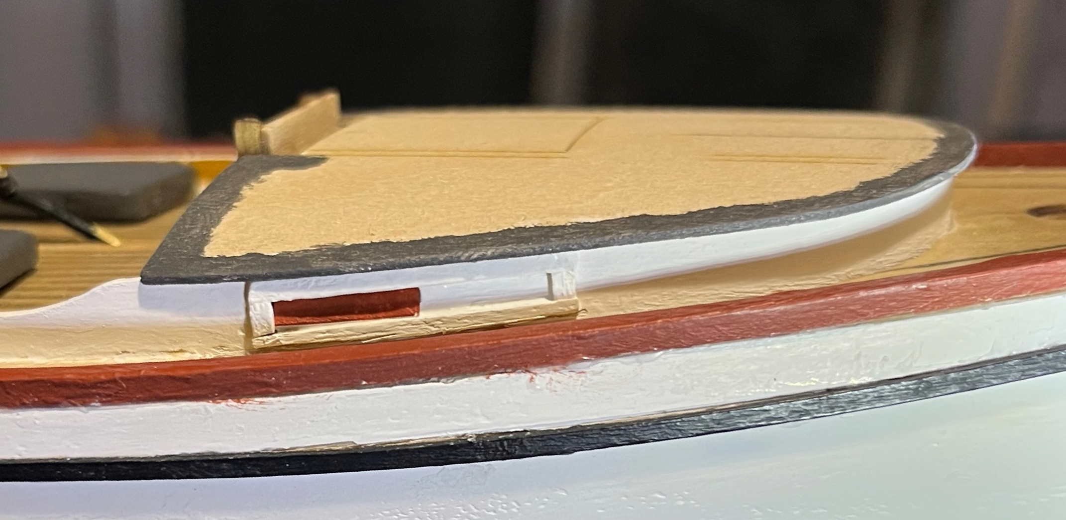
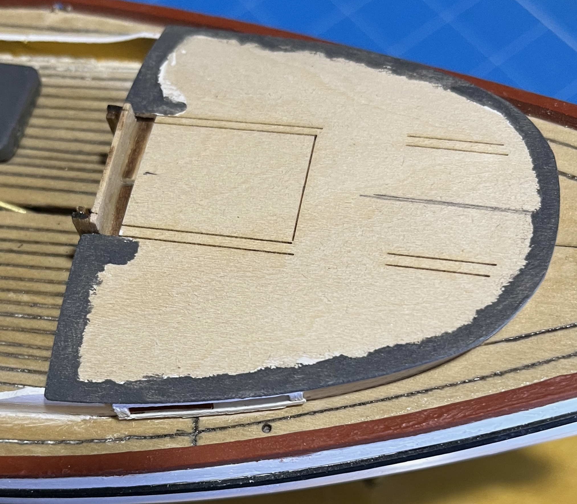
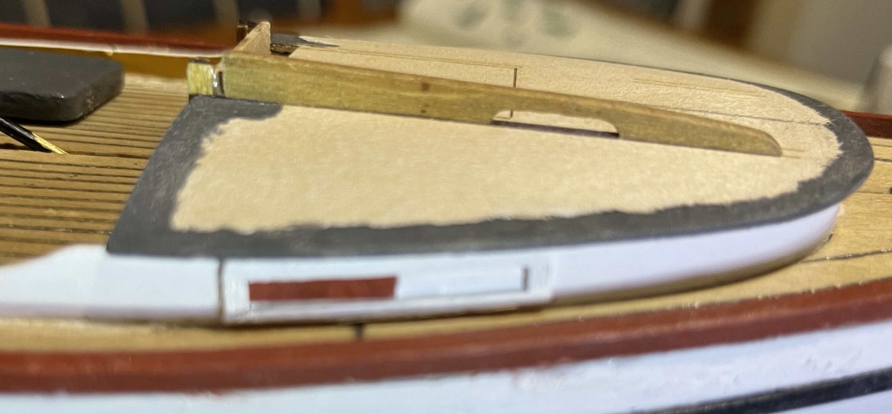
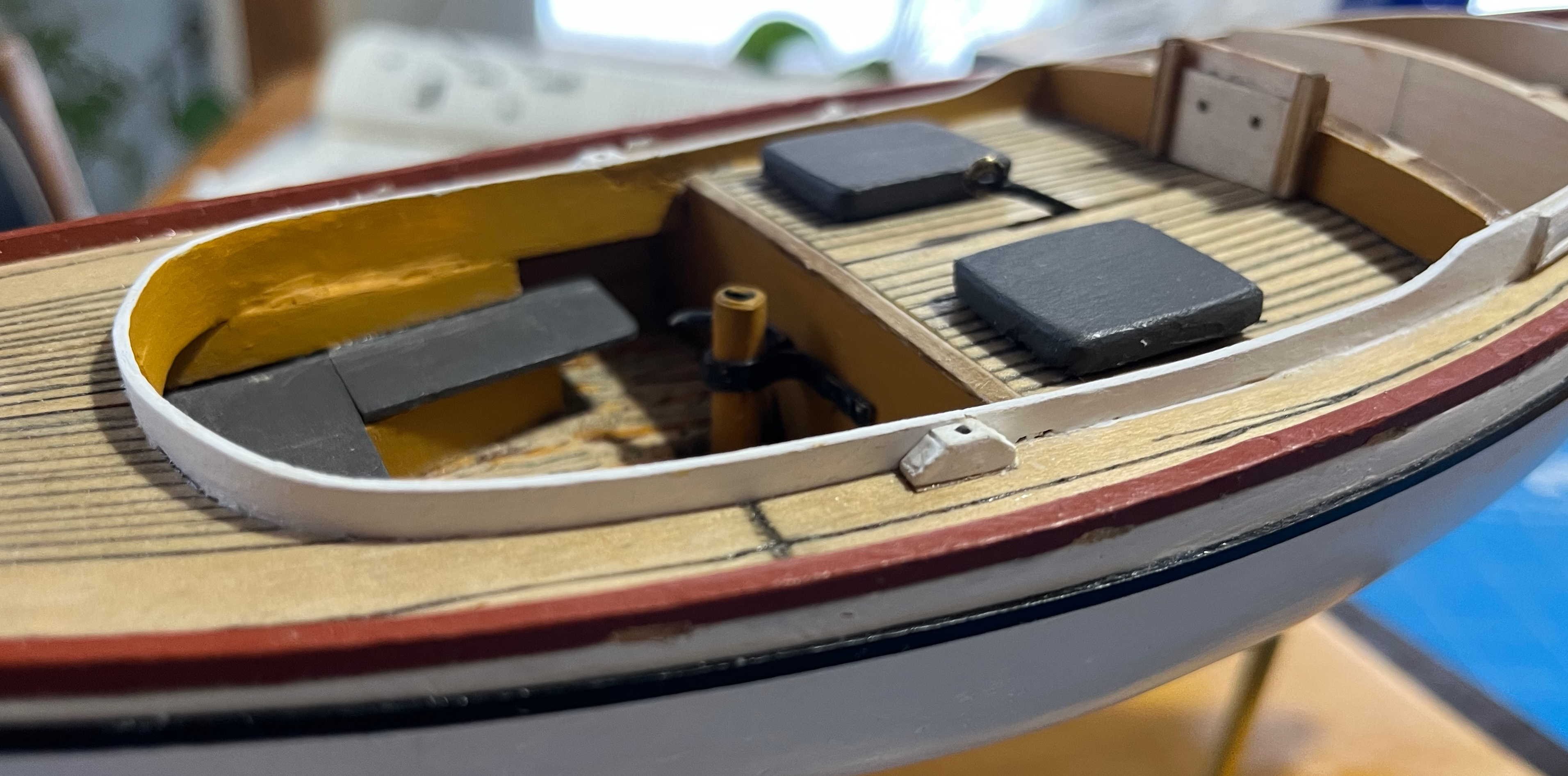
Theoretical ramblings aside, I have got the model's coachroof on. The preliminary was fitting "sliding" shutters to the cuddy ports. After trying and failing to paint card to look like bare pine, I opted to make them in red ochre instead, matching the toe rails. The closed starboard shutter looks quite nice, if you can ignore the yellow-looking shadow from the toerail: I wish I could say the same for the part-open shutter on the port side, but I can't. At least that one will be obscured by the jib sheet when all is done. For the coachroof, I deviated from the Instructions by painting the outer edge before fitting anything. And, even before paint, I marked the centreline in pencil to aid in aligning the forward end with the centreline of the deck: That was a big help. The after end of the roof does not need such marking, as there is a cut-out that fits around the washboard guides. The Instructions recommend wetting the surface of the roof to aid in bending it to the required curve. I found that it bent perfectly well while dry, so skipped that complication. I did do some careful sanding of the parts that the roof sits on, not only to remove char but also to ensure that the upper edge of the cuddy sides was even, port-and-starboard, when seen from the bow or stern (compensating for the sides sinking a bit deeper below the deck on one side while being fitted). With that all done, it was just glue, hold, then put rubber bands around everything and let the glue set. There is a complication, though. If I had pushed the roof back against the washboard supports, it would not have reached to the forward bend of the cuddy sides, while there would have been a broad projection over the bridge deck. Instead, I chose to place the roof further forward, giving an even projection (what would be the eaves of an on-land building) all around. The resulting gap just ahead of the washboard, visible in the above image, will get covered up by the sliding hatch but the slide rails will not fit in the marked spaces on the coachroof. Not a problem but it will need some adjustment. I'm going have think out the details to make everything line up neatly, as shown by dry-fitting one of the rails: Before then, I have to make and fit a base for the charlie noble, as that will get painted along with the roof. But perhaps I should explain: The kit follows Chapelle's reconstruction and has no provision for heating the cuddy. Rathbun's contemporary account, in contrast, states that the boats had wood stoves, to keep the lobsters from freezing during the winter fishery. A stove means that there must have been some way to let the smoke out and, come to that, some sort of flue to let the heat create a sufficient draft to keep the fire burning. Maybe it would have been enough to crack open the sliding hatch but that would have released whatever heated air the stove could generate. Hence, I'm guessing that there was a more elaborate arrangement of what, on land, would be called a chimney. In later decades, the Nautical English term was (and probably still is) a "charlie noble". I'm doubtful that Maine lobstermen of the 1880s would have used the term, as Smyth did not know of it 20 years earlier, but I will call the contraption by its now-familiar name all the same. The charlie noble itself will be delicate, so I won't build it yet, but it will need a solid base. Moreover, in a full-size version, there would have to be some sort of raised support, so that rain or spray on the coachroof could not simply flow down between the metal flue and the surrounding woodwork. I'm going to place the base so that the stove would be against the after bulkhead of the cuddy, close beside the companionway. There, our miniature lobsterman could slide his hatch open and reach for the kettle, when he could spare time for a mug-up, without having to leave the tiller for long enough to climb down into the cuddy. And one final point, while rambling on here: When I read Rathbun's account and his statement of the stove being there to stop the lobsters freezing, I imagined the catch stacked in the cuddy, which would have degraded even the very limited comforts available on board. Having got this far in building the model, however, I have come to a different interpretation: When a ship or boat has tanks part-full of fluid, as with the live wells on a fishing boat, the upper part of the tank should be made as narrow as is practical. The problem is that, when the hull heels, the fluid flows to the lower side -- the opposite of what is wanted for stability. The result is a dangerous "free-surface effect" and the free surface of the fluid needs to be as small as can be to limit the effect. The wells of a Muscongus Bay boat were likely built against the centreboard trunk but their upper parts should not have reached out to the topsides, lest the water slosh far over to leeward. Thus, the enclosed airspace in the cuddy likely extended under the bridge deck and side decks, all the way aft to the cockpit bulkhead. The long, narrow spaces down either side would not have been very practical for stowage (though they might have been good for the fishermen's berths) but they would have let stove-heated warm air circulate around the upper parts of the wells. (The lower parts, below the waterline, would be less liable to freezing, with liquid seawater outside the planking.) That seems to make sense (to me, at least), so I will follow Rathbun in giving my boat the visible parts of a heating system -- though not the stove hidden down in the cuddy! Trevor


-
Kenchington reacted to a post in a topic:
Seguin by Phil B - FINISHED - BlueJacket Shipcrafters - 1:48
-
Present-day yachtsman's correct usage is certainly that any single-masted, fore-and-aft rigged vessel with multiple headsails is a "cutter" (though I have seen "cutter sail" used for a gaff sail, without regard to the associated headsails, in supposedly authoritative sources!). Then again, a sloop is a still a sloop when she sets a spinnaker and spinnaker-staysail or the like, at the same time. Setting two genoas on the same stay, boomed out port and starboard (a rig used when running down the Trades in an ocean cruiser), would not turn a sloop into a cutter, though setting the second sail with its tack near the mast likely would change the designation. Sometimes, definitions are not as definite as they might be. As to the wells: Most vessels with wells for live fish had holes for a free flow of water. ("Had" but maybe not "have": I suspect that modern versions use pumping systems.) However, neither Rathbun nor Chapelle gave any hint of that for the Muscongus Bay boats, so my guess is that they had no holes. Doubly so for those built lapstrake, as that mode of construction relies on the strength of the planks. Only a guess, of course, but I have chosen not to bore holes into the wells of my model. Which raises questions about how the wells and the lobsters were handled. Were there seacocks and piping to flood the well? Or was the water bucketed in? Dropping a lobster into a well would have been easy but how were they got out again? Did the fisherman have to reach in and pick each bug out? Did they have large netting bags, big enough to line the whole well, such that pulling up on the mesh would raise the catch to the level of the bridge deck? And what of clearing out a well when needed? Much of the water could be bucketed out, then a portable pump could move more. But was there a drain at the bottom with a bung of some sort, allowing the water to flow onto the bilge and so to the bilge pump? And what of water in the bilges under the cuddy? It is generally a bad idea to have watertight compartments which trap their own water and upset stability (unless you have a big-ship system of bilge piping and multiple pumps, of course). So there should be a water channel either side of the centreboard trunk but they would have to be sealed off from the wells. Fortunately, none of that would show in a model, so we can ignore the complications! Trevor
-
Smack or Sloop? A boat by any other name … Through the past weeks of pondering how to rectify some of the errors in my model building, I have been indulging myself in contemplating a very different aspect of the prototype: I have used "smack" in the title of this thread, to aid people who search MSW for build logs, but I’m often calling the object in question a "sloop" when I add posts. Both seem to be technically correct but not for the reasons that many readers may suppose. When, in the 1880s and as one contribution to George Goode’s opus on the U.S. fisheries, Richard Rathbun published a contemporary description of the type, he called it simply a “Muscongus Bay boat”. That’s likely what the men who built and worked with the original craft called them, if they needed to add a label at all. Simply “boat” would have served for most purposes. However, decades later Howard Chapelle called this one type all of "sloops", “centreboard lobster smacks” and “centreboard Muscongus Bay sloops” – the latter two alternatives distinguishing them from the deep-keeled Friendship type, which had emerged after Rathbun wrote but was far more familiar by Chapelle’s time. It seems to have been kit manufacturers and the ship-modelling community who discarded “sloop” and settled on the “smack” designation that we now must use in build-log titles on MSW. To dig a bit deeper: SLOOPS: European languages (maybe all languages) tend to have fewer technical terms than there are things to be named, particularly as the things change through time but the terms don’t (or not so quickly). To complicate matters further, ships move around and get copied, so both the things and the terms get adopted by other peoples, speaking other languages, though the things and the terms tend to move separately, sometimes showing up in surprizing combinations. Amongst the resulting confusion, there is a term that gets used for assorted boat types and which shows up in Dutch as "sloep", in French as "chaloupe", Spanish "chalupa", Italian "scialuppa" etc. Two opposed etymological origins have been suggested. One claims that the term is derived from a Proto-Indo-European word for slipping and sliding– hence perhaps the original meaning was a swift boat that slips through the water easily. The alternative claim is that Spanish-speakers took "chalupa" from the 16th-Century Basque term for a whaleboat: "Txalupa". As Basque is the sole remaining version of the languages of Old Europe, from back before the Yamnaya invasions at the start of the Bronze Age introduced the Indo-European language family, those derivations cannot both be true. I very much doubt we will ever know which is wrong. What matters here is that the term existed and was adopted into Nautical English as much as it was into other languages. Uniquely, however, the English managed to adopt two versions of the same term, likely one via Dutch and the other directly from French and/or Spanish, resulting in the alternatives "sloop" and "shallop". Of those two, "shallop" seems always to have meant an open boat, though some were quite large (as with John Smith's shallop, which is often modelled today). That term was common in the 17th Century but seems to have almost died out by the time Muscongus Bay lobster boats gained centreboards. (Smyth did include it in his Word-Book in the 1860s but he included much that was out of date by his own time.) “Sloop”, in contrast, was applied to anything from a small boat up to ship-rigged sloops-of-war (one size smaller than a frigate, in Nelson's day). In Royal Navy usage, the term persisted into the 1940s for the Black Swan class of anti-submarine escorts, which bore no apparent similarities to any sailing sloops. Long before, “sloop” seems to have become particularly popular amongst Anglophone settlers in the New World, perhaps drawing on the Dutch heritage around the Hudson, though it might equally have been just a random choice between sloop, shallop, wherry, bateau, dory and a number of similar alternatives –all meaning (in effect) “boat”– with “sloop” chancing to become to be the one most often encountered. From the southern sugar islands to Canada, the term could be applied to anything from small craft up to substantial, decked cargo carriers – though usually only to craft with single-masted fore-and-aft rigs. They included such famous types as the 18th Century Bermuda sloops and, decades later, the Hudson River sloops. Thus, Chapelle was well within his rights to call the Muscongus Bay centreboarders “sloops”. If pressed, the men who built and used them would probably have accepted that designation for their craft. Note that, at the time, the term had nothing to do with the number of headsails. Muscongus Bay centreboard boats had a single jib (as did Hudson River sloops) but the later Friendship sloops usually carried multiple headsails. That brings up another common feature of nautical terminology: Ship and boat type names were often first applied to groups identified by hull form or intended purpose, then linked to the typical rigs of those types until finally (and mostly in the decades around 1900) the terms were re-defined in relation to rigs. There are lots of examples: For just one, “ship” and “barque” or “bark” were originally synonymous but gradually came to be distinguished by hull size. As rigs developed, larger hulls went with square canvas on the mizzen mast, smaller vessels making do without. Hence, it became possible to speak of “ship-rigged” and “barque-rigged” vessels, before the maritime lexicographers settled on the presence of crossed yards on every mast being the defining feature of a “ship” and their absence from the aftermost mast distinguishing a “barque”. That process of type names becoming defined by rig continued to the end of working sail, with the English beginning to refer to the particular spritsail rig of Thames sailing barges (very familiar to Londoners, hence to the elite literati) as “barge rig”, from which there came to be a few “barge-rigged” yachts (though nobody got quite as far as re-defining “barge” by a rig before the end). Basil Greenhill (long-time Director of the museum in Greenwich) once wrote scathingly about that perversion of meaning and declared that nobody would name a type of powered craft by its engine (despite "steamers" and "motor ships" having been distinguished for decades). And yet, when I interviewed a sample of Nova Scotian inshore fishermen in 1990-91, they identified their Cape-Island type lobster boats as “diesels” or “gas boats” – the greater range and reliability of marine diesels having critical consequences for their fishing. Moreover, they referred to the standard, mass-produced type of aluminium 16 fters as “outboards”, whether or not those had motors on the transom at the time, whereas V-bottom GRP boats (“speedboats”) and inflatables (“rubber duckies”) were never “outboards”, even when driven by an outboard motor. The evolution of nautical language has not stopped! Putting all that together, it’s a pretty good guess that somebody somewhere came to associate single-headsail rigs with a boat type known as a “sloop” and drew a distinction from a different type known as a “cutter”, which happened to have multiple headsails, leading to other single-headsail boats being called “sloop-rigged” in distinction from “cutter-rigged” alternatives. I don’t know whether anyone has traced that linguistic transition to its source but I suspect that the America’s Cup had something to do with it. The New York Yacht Club’s members naturally called their single-masted racers “sloops” and they learned the advantages of single-headsail rigs in windward performance from the Hudson River sloops, which were adapted for working up and down the river, hence often beating to windward within a confining channel. The English challengers for the Auld Mug called their yachts “cutters”, drawing on the traditions of fast revenue cutters, pilot cutters and the swift fresh-fish carrying “cutters” like Hewett’s Ranger (another vessel often recreated in miniature today). Equally naturally, those English yachts had multi-headsail rigs, as almost all other types did at the time. From American sloops with single headsails racing against English cutters with several, it would have been an easy (if seriously misleading) step to define “sloop” as a single-masted craft with one headsail. SMACKS: So much for the “sloop” label applied to Muscongus Bay boats. Meanwhile, the Nautical English term "smack" has Dutch equivalents as "smak" or simply "smack". It is said to be derived from Norse "snaka" -- meaning "snake" (or better "serpent") and once used for the largest and longest of the Medieval royal longships of Denmark and Norway (themselves larger versions of the Viking pirate ships). By the 16th Century, the Dutch used the term for smaller vessels, probably ones working in the coasting trades. In 1750, Blanckley defined its English meaning (perhaps with an eye to naval contexts) as "necessary Transporting Vessels, with one Mast and half Spreet-sail" -- a half-sprit sail being an intermediary between a spritsail and a standing gaff. By 1769, Falconer could modify that definition to: " a small vessel commonly rigged as a sloop or hoy, used in the coasting or fishing trade; or as a tender in the King’s service". To him. "sloops" were gaff-rigged (without numbers of headsails specified). Hoys were little different in their rigs, though Falconer understood sloops as having booms as well as gaffs, whereas the gaff sails of hoys had no boom. Thus, to Falconer, smacks could have boomed or boomless, single-masted gaff rigs. I'd not take dictionary definitions so seriously as to suggest that smacks were adopted for fishing between 1750 and 1769 but there does seem to have been some change in usage during the 18th Century. From Medieval times, the North Sea cod fisheries had used vessels called "doggers" – though both hulls and rigs doubtless evolved very considerably through the centuries, without the term changing. (Doggers fished the Dogger Bank, which is still its name, for a species that the Medieval Dutch called "doggervis". Nobidy seem sto know whether that was codfish caught on the codfish bank by cod-fishing vessels, or doggers landing fish named after the boats, which they had caught on their eponymous bank.) However, after centuries of stable terminology for changing technology, in the 18th Century the craft used in the cod fishery began to be called “smacks”. Maybe coastal cargo carriers were adopted for fishing. Maybe the term was appropriated for the final development of what had been called "doggers". Either way, “smack” became the normal term. At much the same time, the Essex oystermen also adopted what they called “smacks”. Essex is the English county immediately east of London and north of the Thames. In that era, before the development of the metropolis, a man could live in Essex and yet within sight of the Tower, hence within easy reach of the City’s consumers. Thus, they were able to supply fresh seafood to a large market. Today, Essex fishermen drag for shellfish in the estuaries of their county’s east coast but in former centuries they reached out far afield, fishing out the oysters of the Texel bank (off the Dutch coast), then working down-channel to Cornwall and across to the French side, eventually exploiting the rich grounds around Jersey – until they depleted the last of the offshore beds in the later 19th Century. When they passed through the waters off Devon, the oyster smacks were watched by fishermen of Brixham, whose preferred gear was a beam trawl, used in harvesting flatfish. Theirs was then a very small-scale fishery – so small that, at the end of a day’s fishing, a Brixham man could wrap his net around its beam, hoist the whole thing onto his shoulder and carry it home. In the 1750s, however, other Englishmen were busy building turnpike roads – roads with surfaces good enough for fast, wheeled vehicles. The first to be finished, in 1749, was naturally enough the connection from the capital, London, to the major naval base, Portsmouth. But the latter was only a hundred miles downwind from Brixham, with the prevailing southwesterlies, meaning that a fast cutter could carry fresh fish from the Devon harbour to the turnpike in under 24 hours. From there to London needed a new form of road vehicle, the “fish machine”, with spring suspension and two cantering horses – the first swift road vehicles in Britain, preceding fast mail coaches by some decades, and far cheaper per unit weight transported than the pony trains, which had been the only viable fast transport over the old, rough roads. With that new, rapid and affordable access to London’s consumers, Brixham men exchanged their small boats for smacks, able to make longer trips and to tow larger nets. Thus equipped, they expanded their fishing throughout the Channel, then on to the North Sea. Many men moved north and eventually settled in Hull and Grimsby, which became the world’s two greatest fishing ports – until surpassed by Murmansk after 1945. English bottom-fishing came to be so dominated by beam-trawling smacks that, by the mid-19th Century, “smack” was understood to mean a beam trawler, unless something else was specified (as in “cod smack”, meaning a vessel used in fishing with baited hooks). Until the 1860s, they were all single-masted but, as larger hulls proved economically viable, their very long main booms became hard to handle with a small trawling crew, so the sail area was broken up. The larger smacks were given a mizzen mast aft – what the fishermen called “dandy rigged”, though yachtsmen saw them as “ketches”. The end of that development produced vessels like the oft-modelled Erycina, a fine example of a Plymouth trawling smack of the early 20th Century (though, in a perverse twist, contemporary Brixham men would have called her a “big sloop”!). The New England fisheries began as an export industry and the cod they caught were necessarily salted and dried, preserving the product for transport to consumers. The London market, in contrast, preferred fresh fish, indeed fish that were alive until they reached Billingsgate. To that end, some boats had been fitted with free-flooding live-wells from the 17th Century at least. Once smacks replaced doggers, those fitted with wells were called, naturally enough, “well smacks”. The (Old) English type of fishing smack was tried in New England but never caught on. However, a market for fresh fish did emerge in the coastal cities, particularly Boston and New York, from the 1820s. In time, the fisheries would adopt icing to preserve the quality of their catches destined to be sold fresh – drawing on the emerging New England ice industry, which exploited the abundant lakes and cold winters of the region. Before that, however, the shipwrights of Essex, Massachusetts adopted the solution familiar in their namesake region across The Pond and, from 1831, built vessels with live wells. As it was an (Old) English idea, the New England fishermen adopted the term that came with the concept and called any vessel with a live well a “well smack”, even when there was no other similarity to an (Old) English fishing smack. By the time that Rathbun described the Muscongus Bay boats, that usage was well established and “well smack”, typically shortened to “smack”, had become the accepted New England term for a fishing vessel with a live well, regardless of hull form or rig. Which is all a very long way of saying that a Muscongus Bay centreboarder, such as the one represented by the Model Shipways kit, was a “sloop” because single-masted watercraft rigged fore-and-aft were generally called “sloops” in North America, regardless of their number of headsails. She was also a “smack” because she was fitted with live wells for a catch of lobsters – despite having almost nothing in common with English trawling smacks like Erycina. “Sloop”, “smack” and “boat”: All equally valid terms for the same boat type 😄 Trevor
-
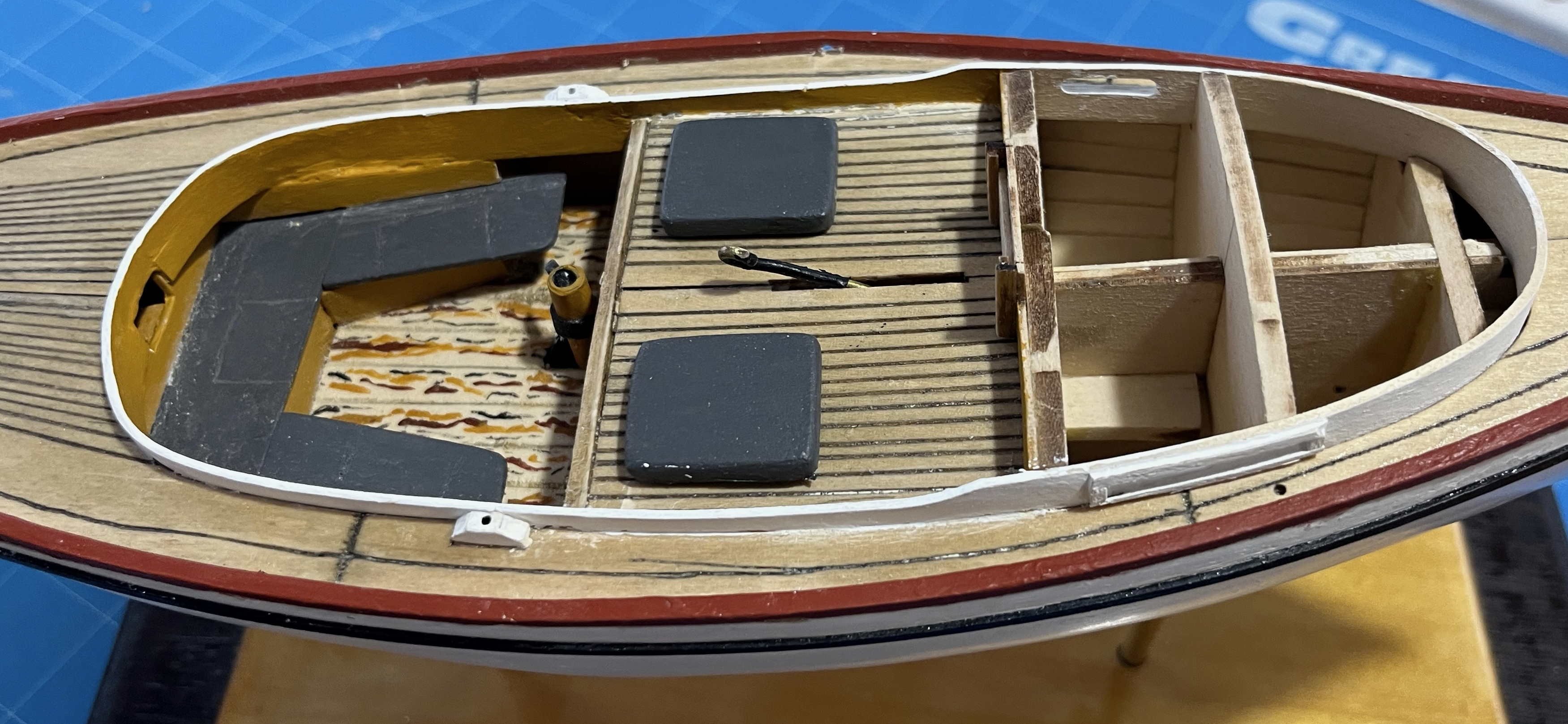
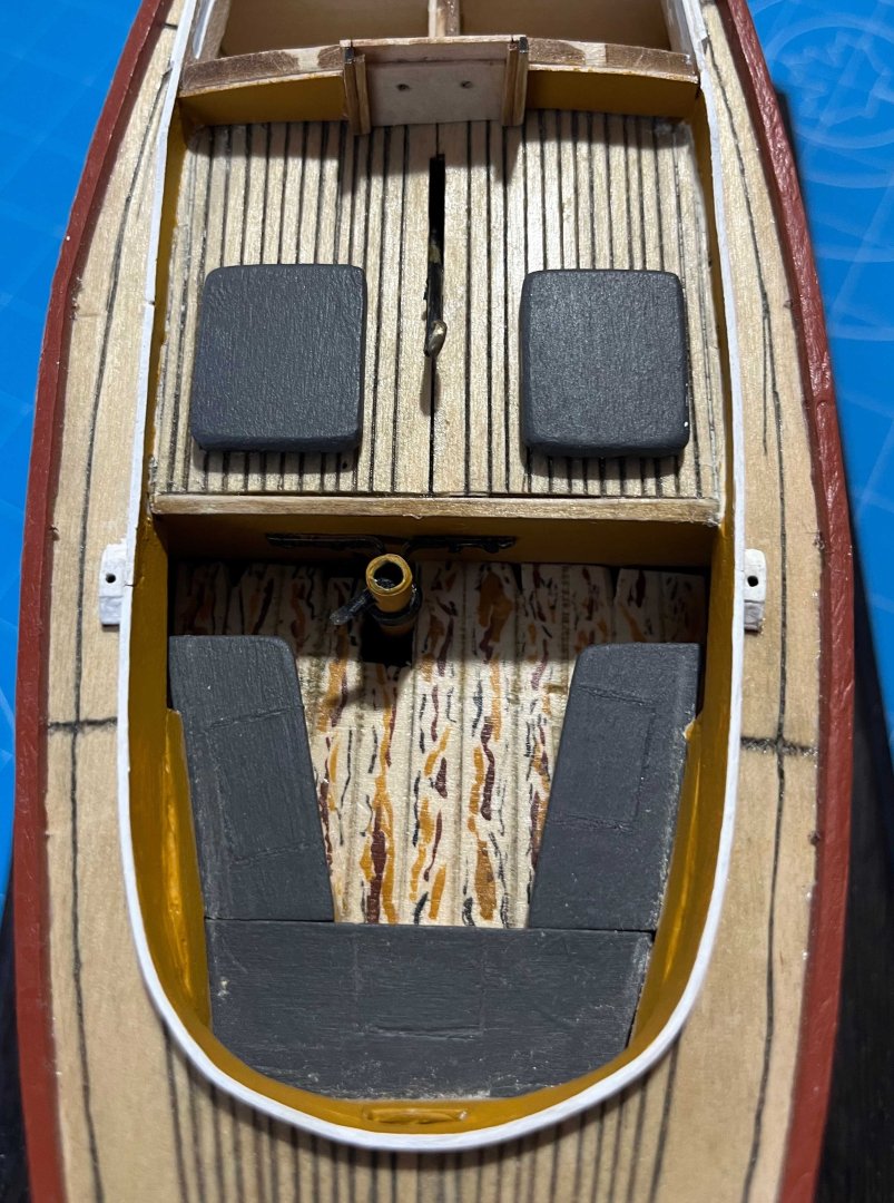
After a little off-model experimentation, yesterday I did some moulding and modelling with ordinary wood filler, then overnight thorough drying. Today started with gentle sanding, followed by two coats of yellow ochre inboard and two of white outboard and around the top edge of the coaming. I glued the lobster-well hatches on once the inboard paint was done. The end result isn't as pretty as I could wish but I am satisfied: For anybody thinking of following my version of the lobster-well hatches: Looking at them now, I would have opted for thinner material for the top, though I'm happy with them slightly raised off the deck by having the kit-supplied hatches as an under-layer. Next up: Cuddy sliding shutters, then the coachroof, followed by the sliding hatch. I will touch-up the grey paint while doing the coachroof. Still have to touch up the WoP on the deck, finish the centreboard control rod etc., but completion of then hull gets closer and closer! Trevor


-
Lovely pump! Your cockpit seats look great too. For the comfort of your miniature fishermen (when they come to life in the dark hours between midnight and dawn), I hope the pump handle is (also miraculously) able to be pushed down into funnel! When the wind dies and the oars have to be shipped, the man rowing will have to sit on the centreline of the bridge deck's edge, with his feet in the cockpit. A pump handle between his thighs would be distressing 🫢 Trevor
-
You made a lovely job of those gudgeons! Wish mine had gone so well. Trevor
-
And you even have my far-distant cousin, James Daniel Kinchington, there at the controls of his engine. Lovely! To return our hijacking of this thread to nautical matters: JDK's elder son was a stoker in the Royal Navy, then worked for HM Coastguard -- before becoming a publican. More especially, JDK's cousin (son of his mother's elder sister) was Absalom Blachford, sometime skipper of King Edward VII's yacht Britannia. But that's enough name-dropping for one day! Trevor
-
There was an interesting reversal in technological progress, as well as marked local variation, in agricultural machinery. A man of my name was enumerated in the 1871 English census as an operator of steam ploughs -- hauled to and fro across the wide wheat fields of Wiltshire on a steel cable worked by a traction engine. I doubt that there were many such rigs in the USA at that time. Yet diesel-powered tractors came so late to (Old) England that in my mother's country, in Devon, the farms were still worked by heavy horses through to 1945 -- long after internal-combustion power had taken over on this side of the Atlantic. When I was a kid in the '60s, the local farm still had the old harness hanging on the walls of one of the lofts. My maternal grandfather drove a steamroller, from the 1920s on, building the new motor roads. In 1942–43, they had to build approach roads to the new USAAF airfields constructed for the D-Day invasion. The locals had the roller (powered by steam) but otherwise men with picks and shovels. One day, one of the American engineers said: "You guys need a bulldozer!" My grandfather remembered his response as: "What's a bulldozer?" A man with decades of experience in road building had simply never heard of such a thing. Which is to say that a model showing Missouri circa 1900 needs to show Missouri circa 1900 and it may be very, very different from what was being done somewhere else, even close by, or "somewhen" else a decade earlier or later! Trevor