HOLIDAY DONATION DRIVE - SUPPORT MSW - DO YOUR PART TO KEEP THIS GREAT FORUM GOING! (Only 24 donations so far out of 49,000 members - C'mon guys!)
×


aydingocer
-
Posts
916 -
Joined
-
Last visited
Content Type
Profiles
Forums
Gallery
Events
Everything posted by aydingocer
-
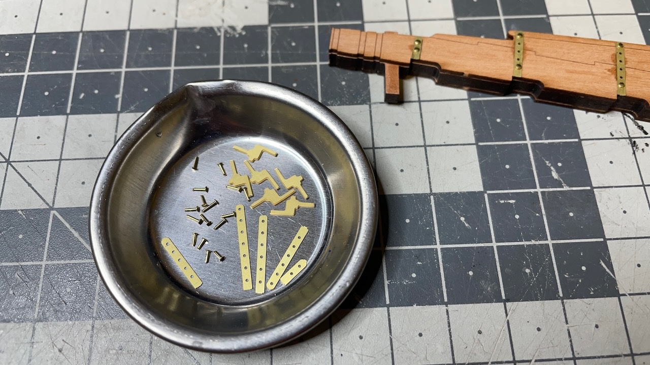
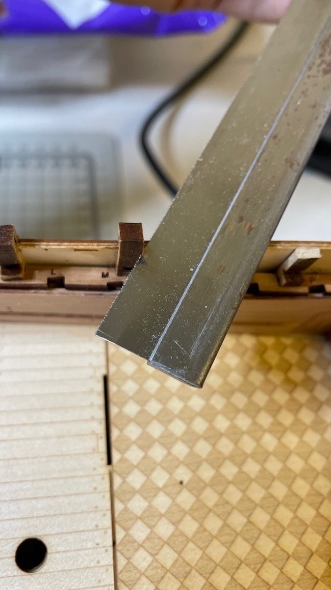
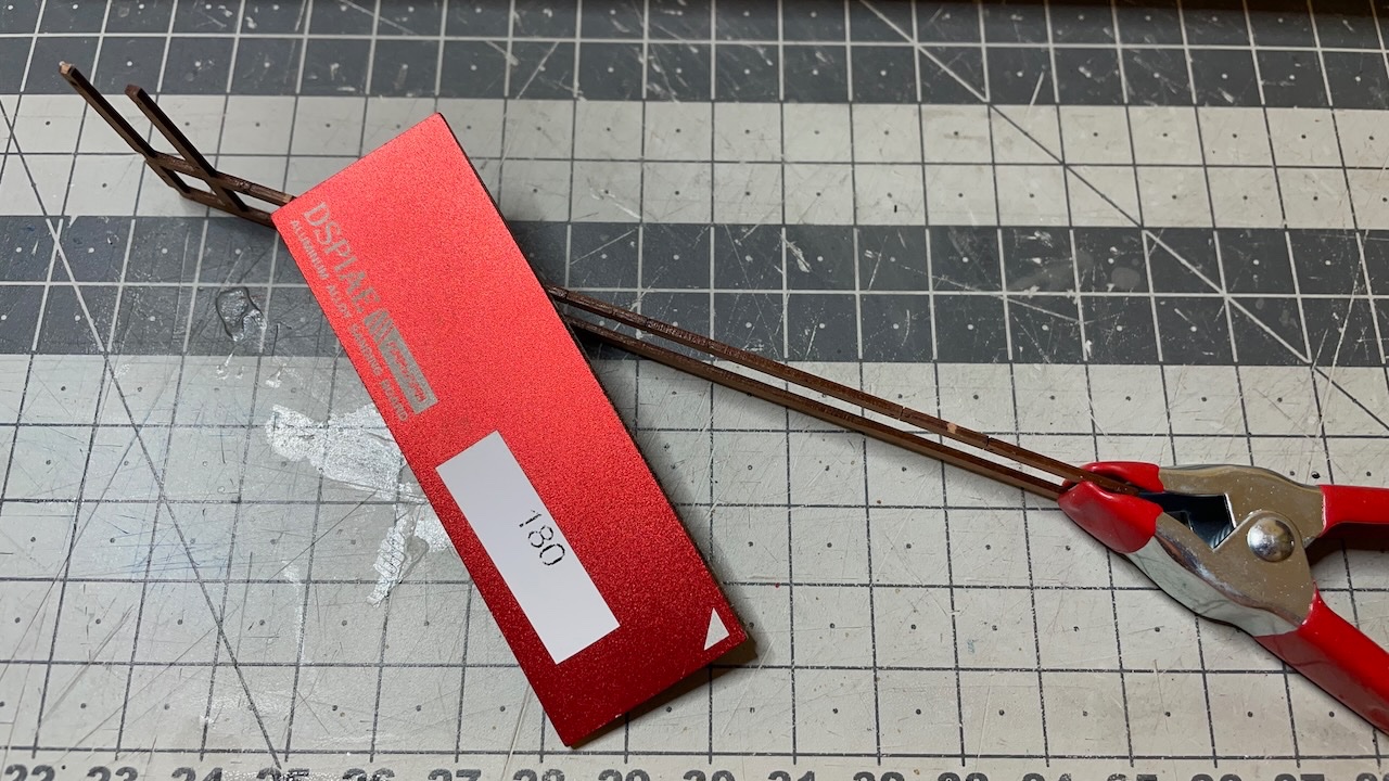
 Photo 313: Need to shorten the nails (to around 2mm) to insert them from both sides. Instructions say we will need the cut-off pieces later so I keep them.
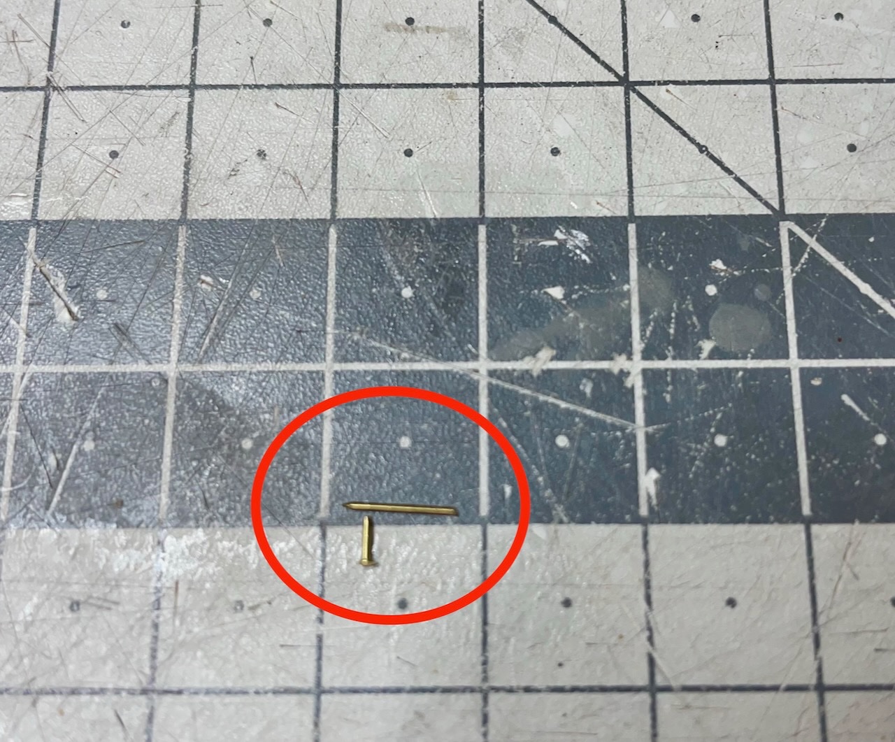
- 426 replies
-
- 2
-

-
- Vanguard Models
- Sphinx
- (and 1 more)
-
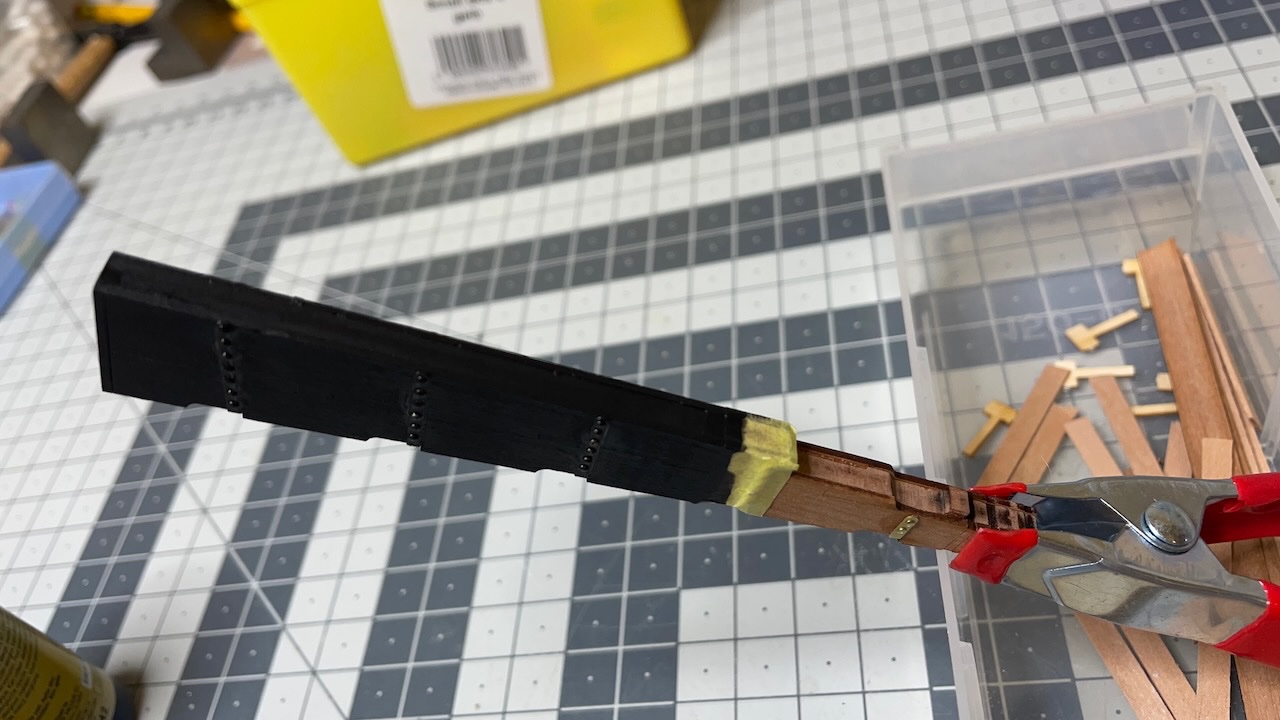
Photo 311: Also removed the Rudder and Gudgeon Pintle Patterns. I had to check from the manual several times to spell this part name correctly Photo 312: Parts ready for assembly.
- 426 replies
-
- 4
-
-
- Vanguard Models
- Sphinx
- (and 1 more)
-
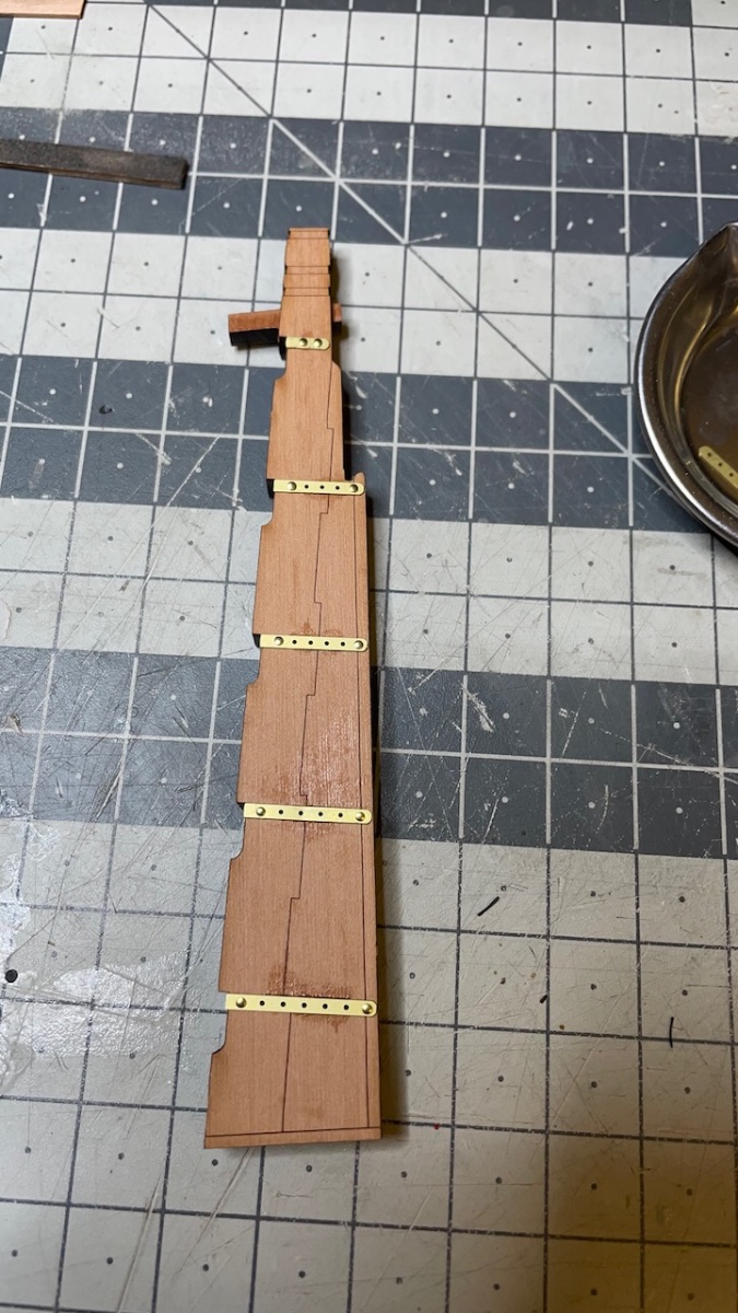
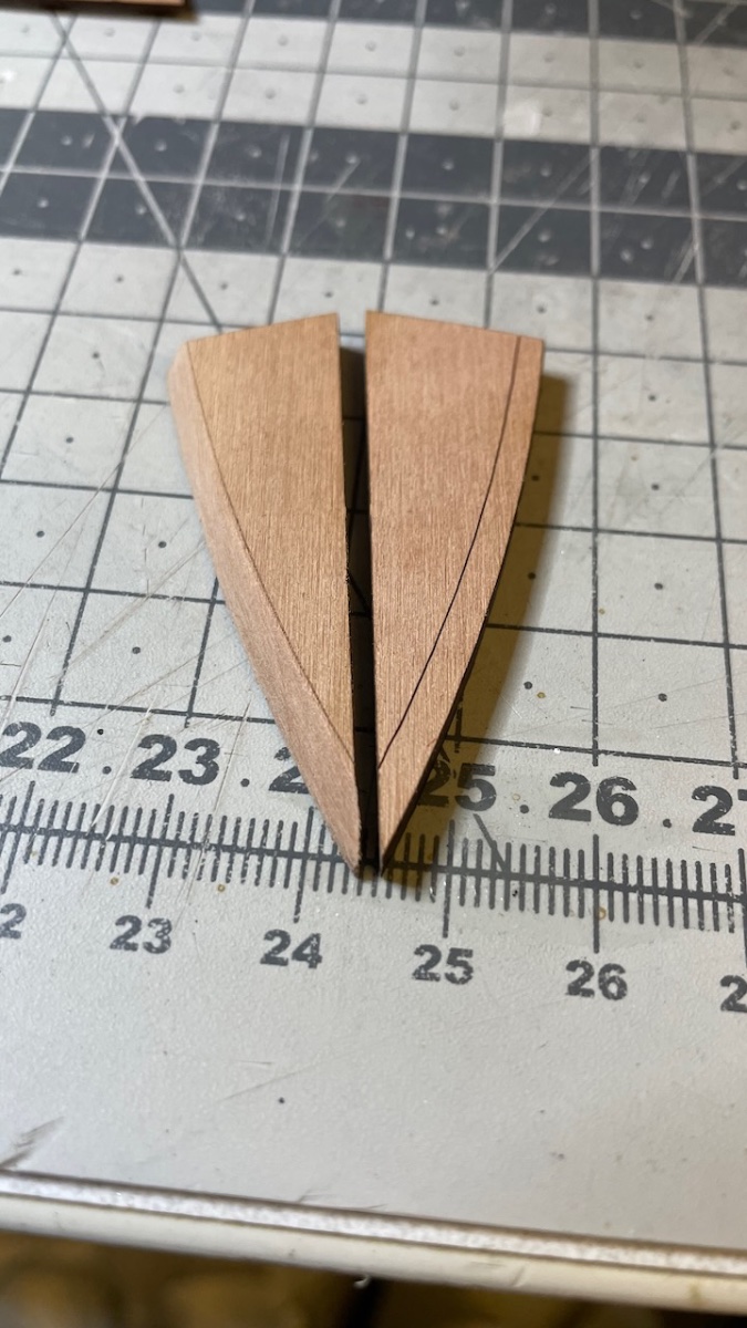
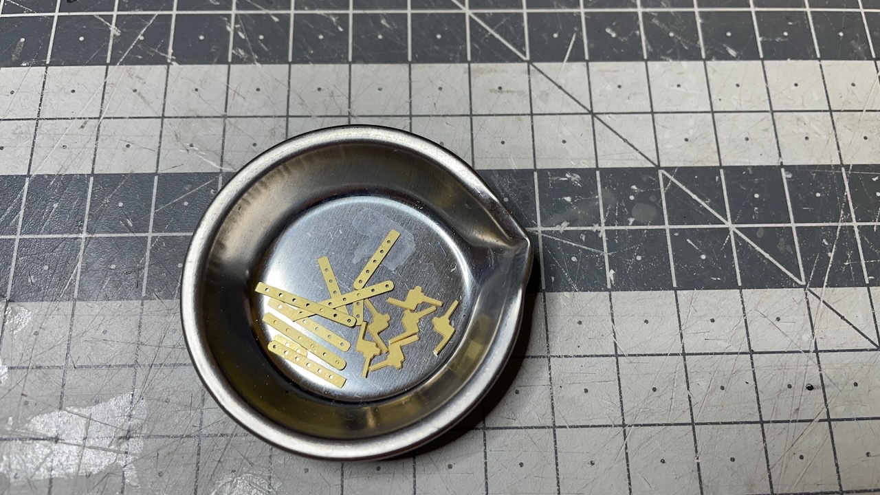
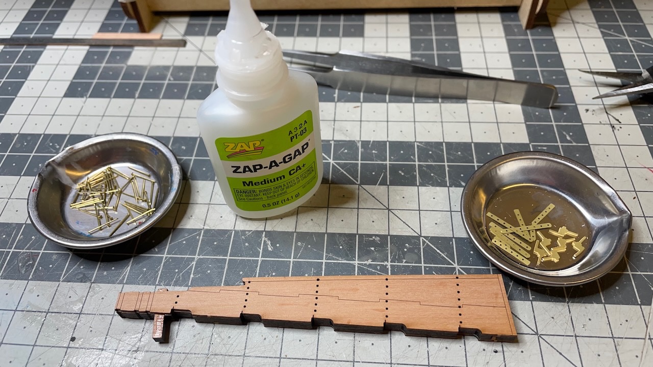
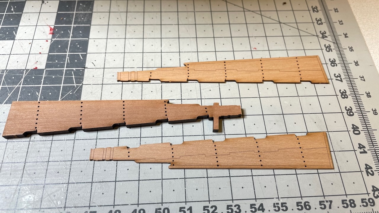
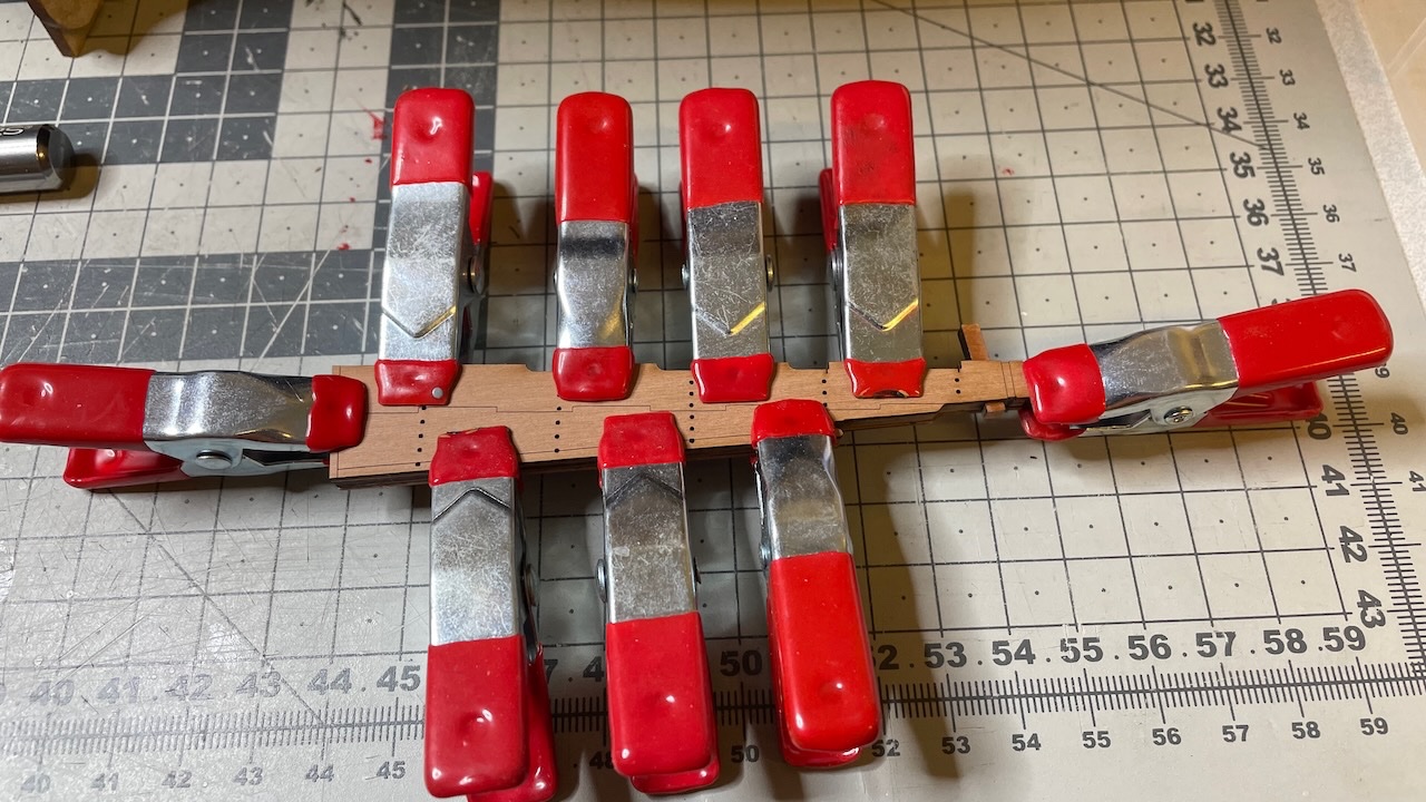
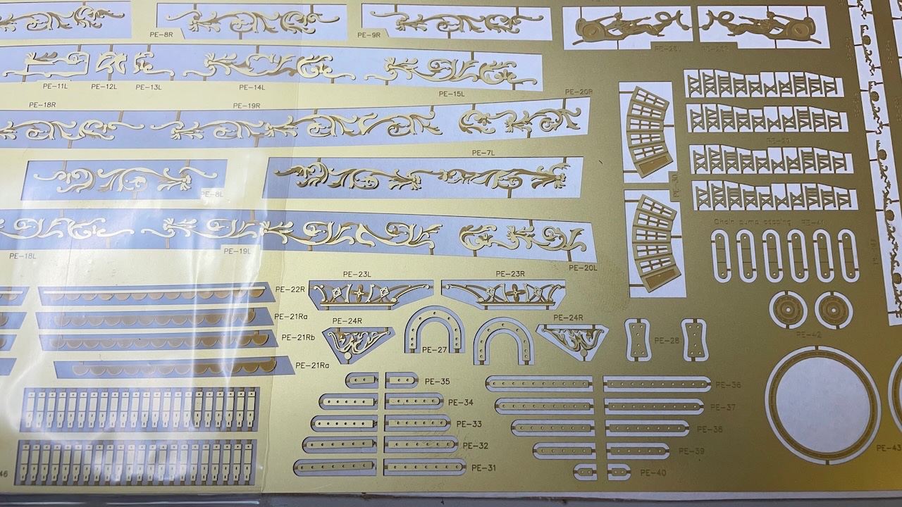
Rudder construction. Photo 308: Removed 3 rudder pieces. The central piece is thicker, while the two outer pieces with engraved patterns are thinner. Photo 309: Glued together carefully ensuring that the pinholes align. Photo 310: First photo ethced work of this construction. Very delicate parts. We need PE-31 to P-35 for rudder.
- 426 replies
-
- 4
-
-
- Vanguard Models
- Sphinx
- (and 1 more)
-
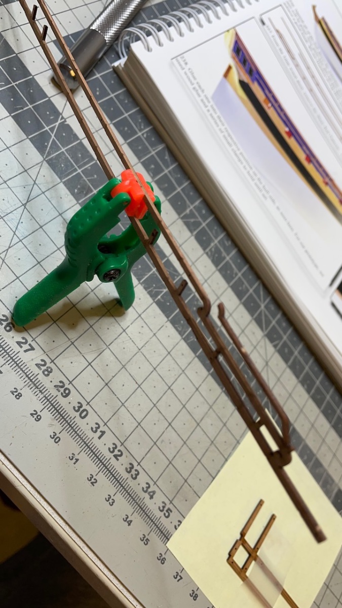
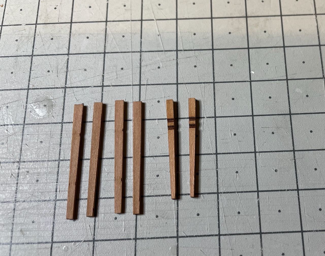
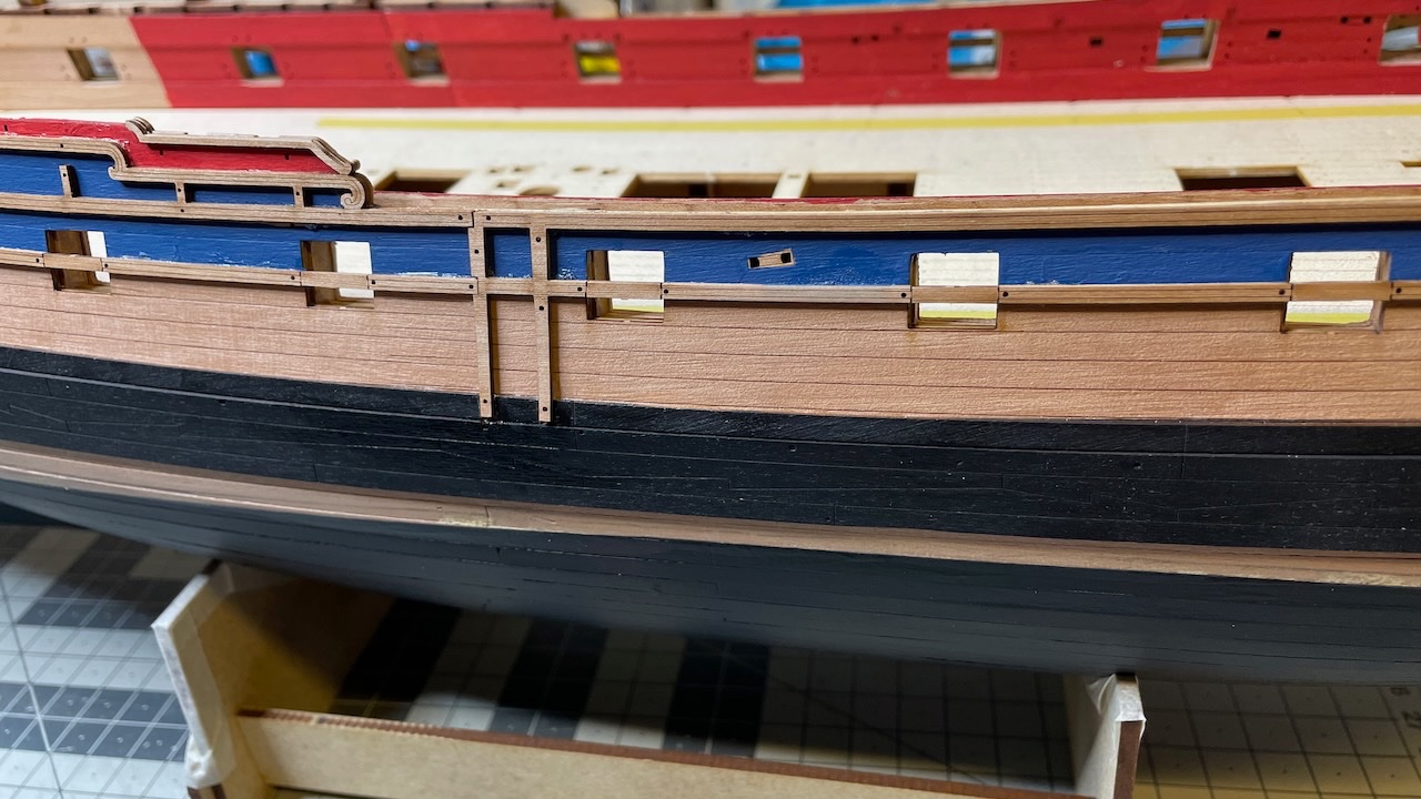
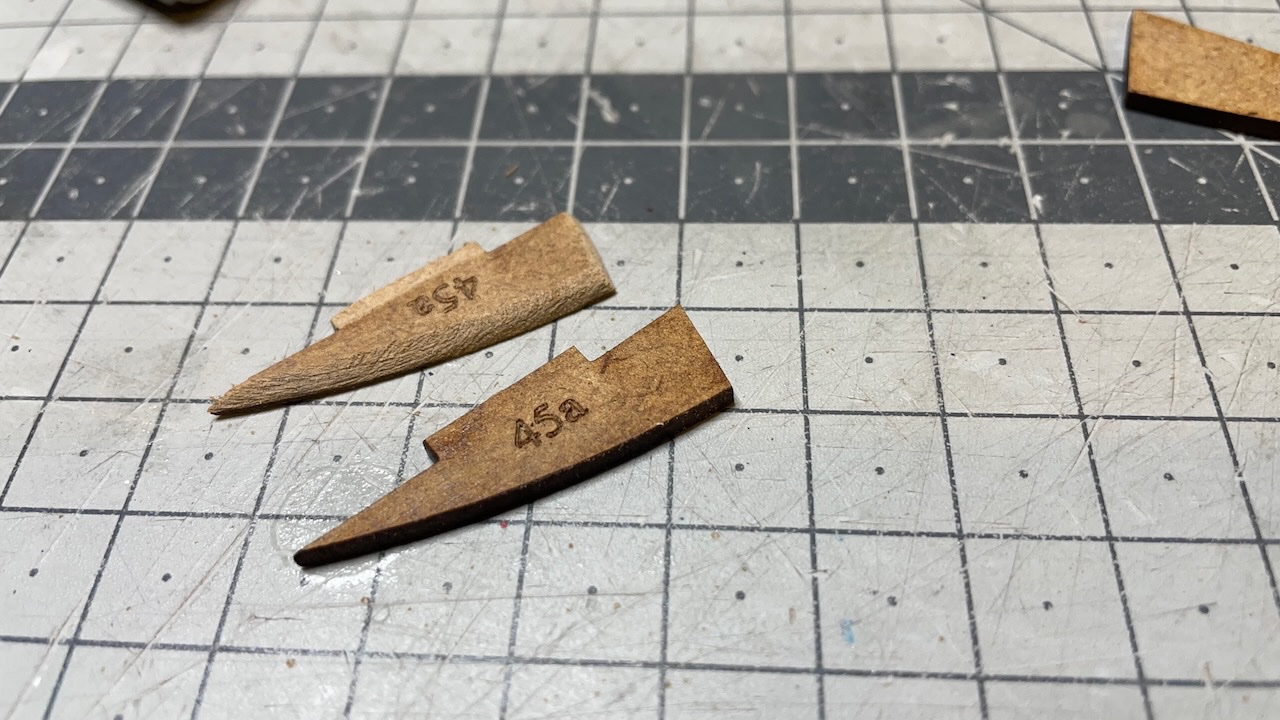
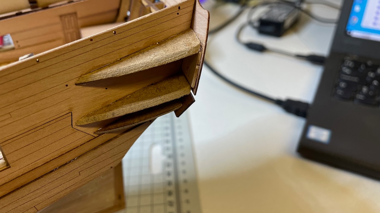
Build day 36: 3hrs / Total 76 hours Today I spent about 3 hours on - Side Fender Patterns and Chess Tree Patterns, - rudder (still in progress) Photos 306-307: Removed the Side Fender Patterns (2 for each side) and Chess Tree Patterns from the sheet and glued in place. I didn't check ahead if the sides will be hidden or not later but I still removed laser char from the sides.
- 426 replies
-
- 3
-
-
- Vanguard Models
- Sphinx
- (and 1 more)
-
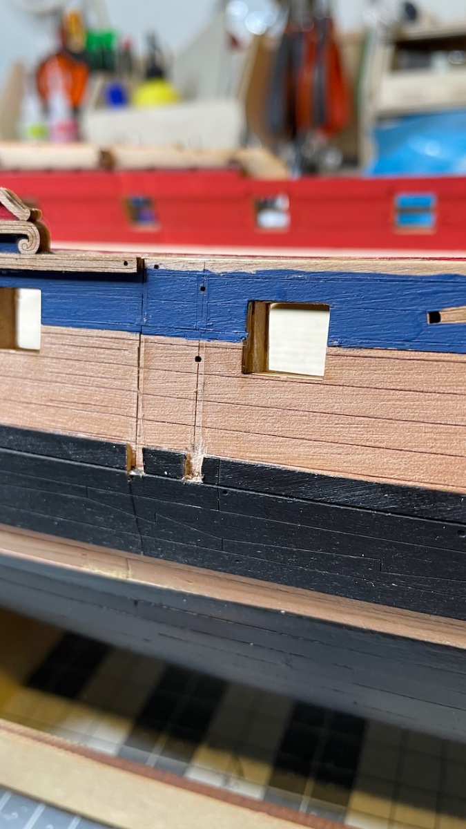
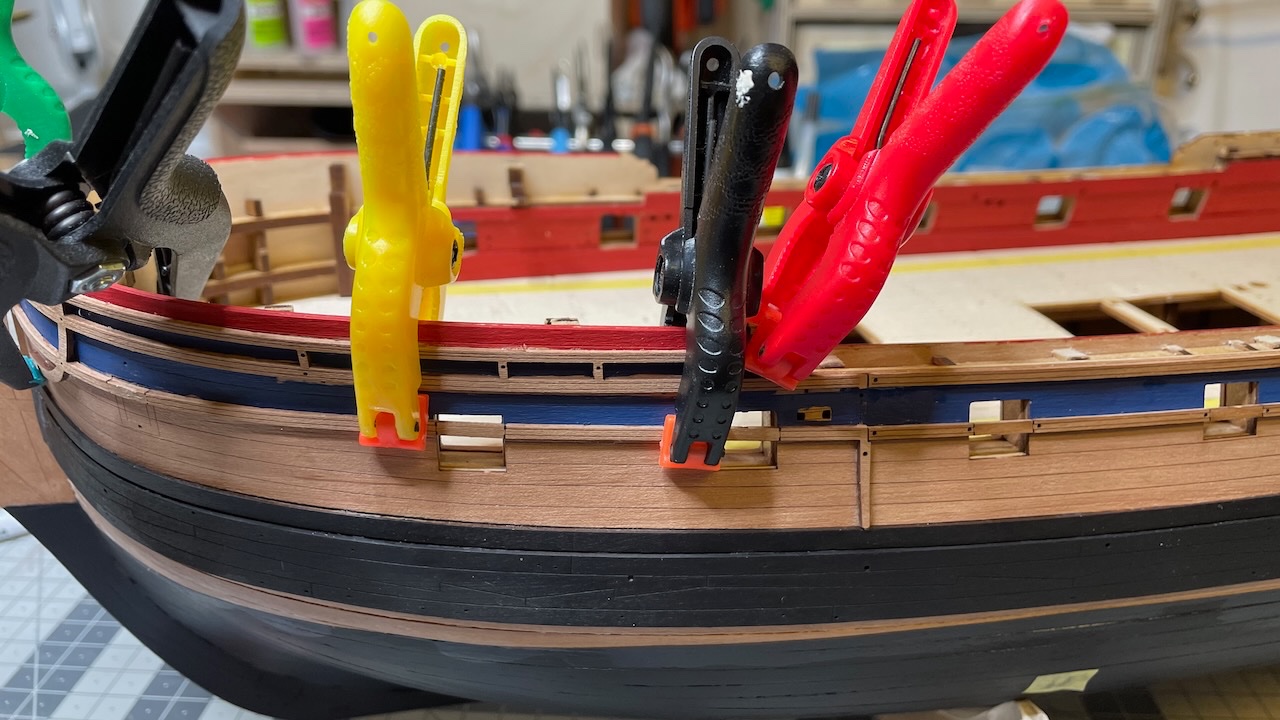
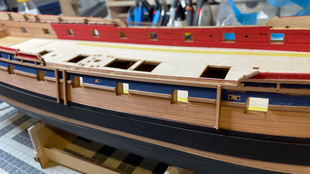
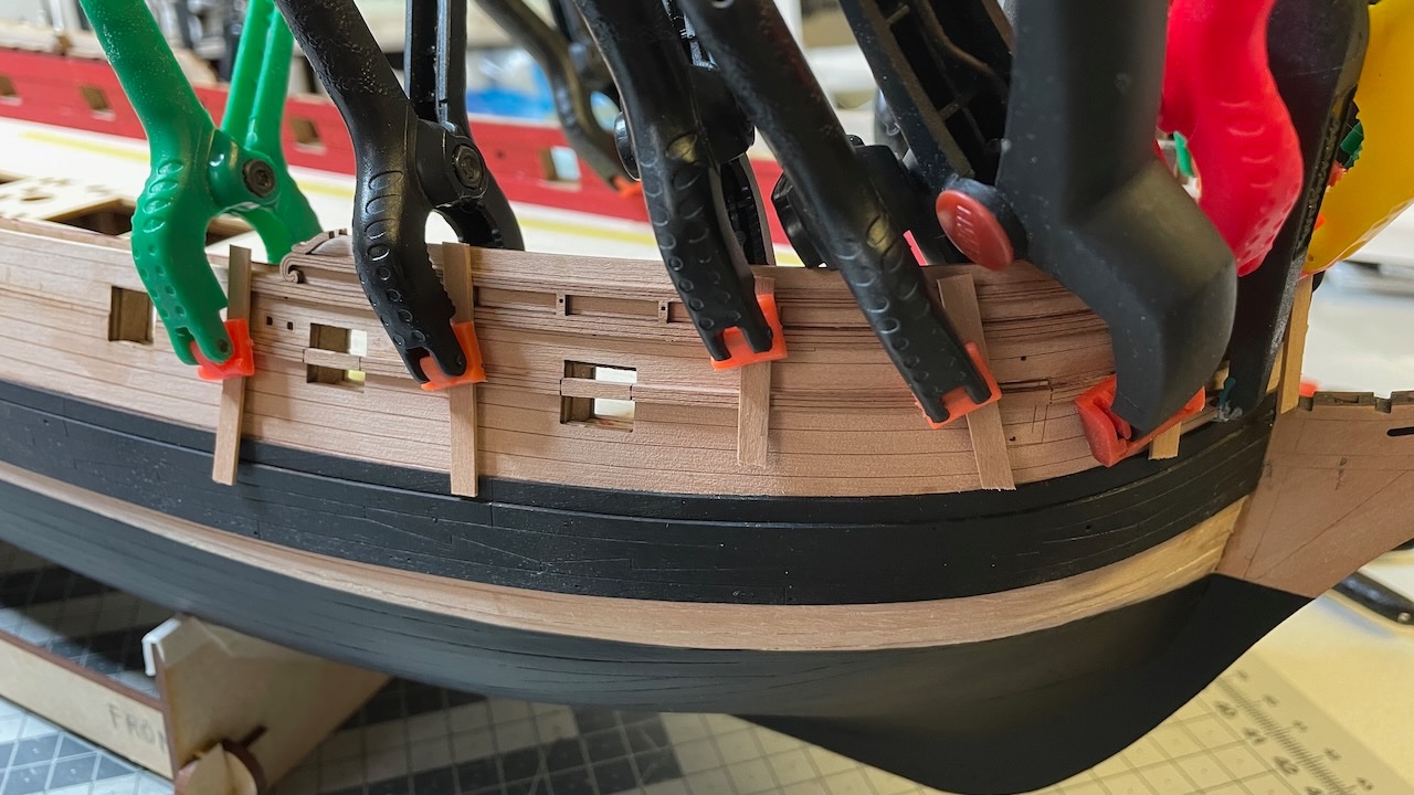
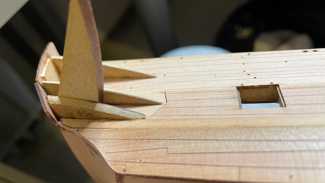
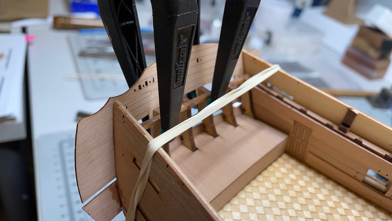
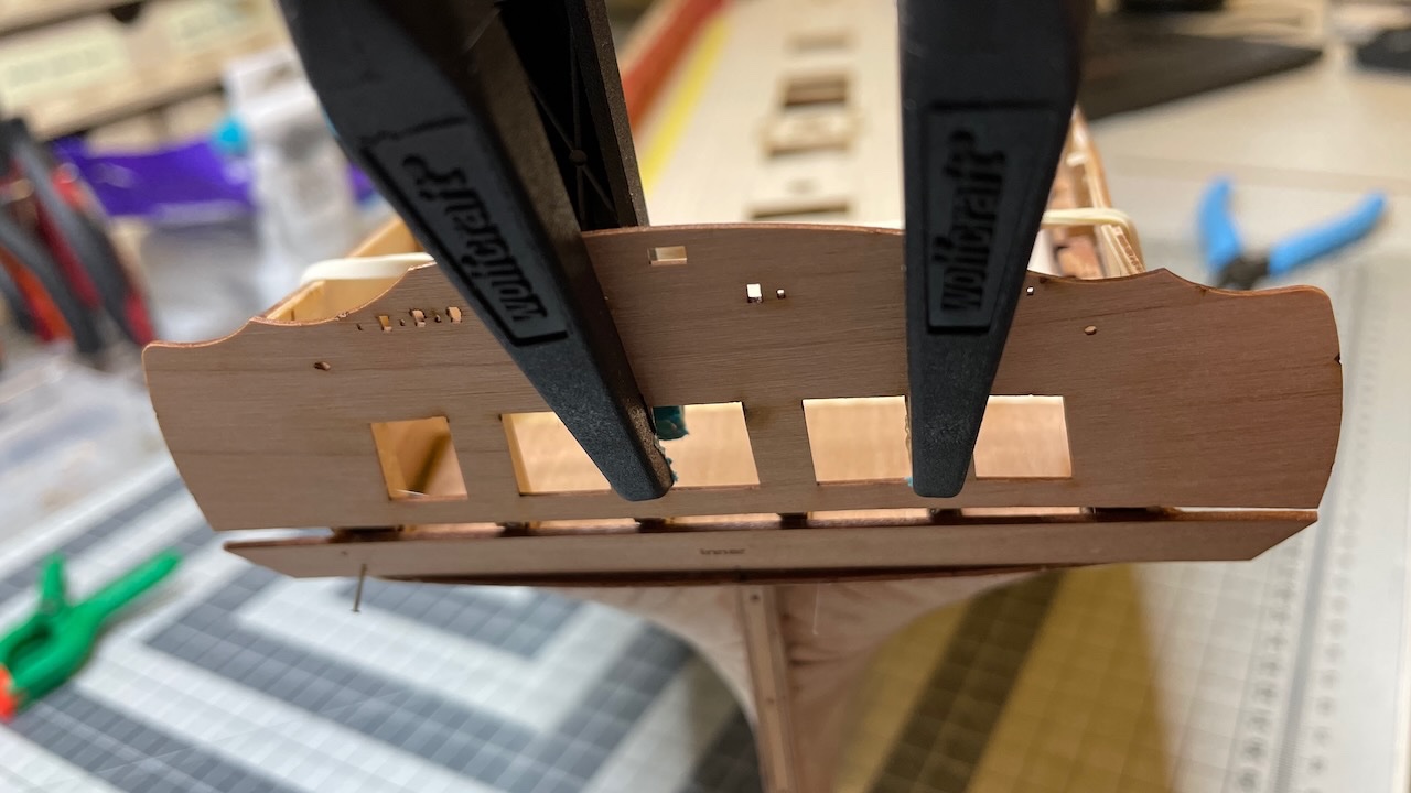
Gluing the rail patterns is complete. Photos 303-305: At one part you need to remove part of the upper wale so the fender will sit into it.

- 426 replies
-
- 6
-
-
- Vanguard Models
- Sphinx
- (and 1 more)
-
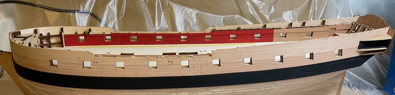
Photo 301: Painted in Vallejo Prussian Blue and Vallejo Air Color Red. The blank areas in the middle will be covered by rail patterns.
- 426 replies
-
- 3
-
-
- Vanguard Models
- Sphinx
- (and 1 more)
-
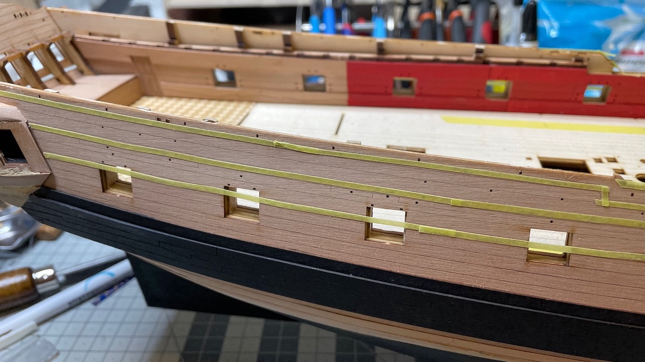
Photos 299-300: Rail patterns masked, ready for varnish. I applied acrylic matte white Admiraly varnish from Caldercraft using brush.
- 426 replies
-
- 2
-
-
- Vanguard Models
- Sphinx
- (and 1 more)
-
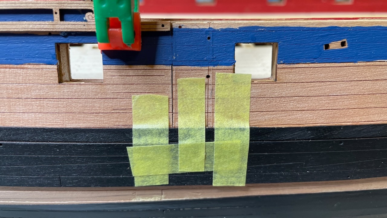
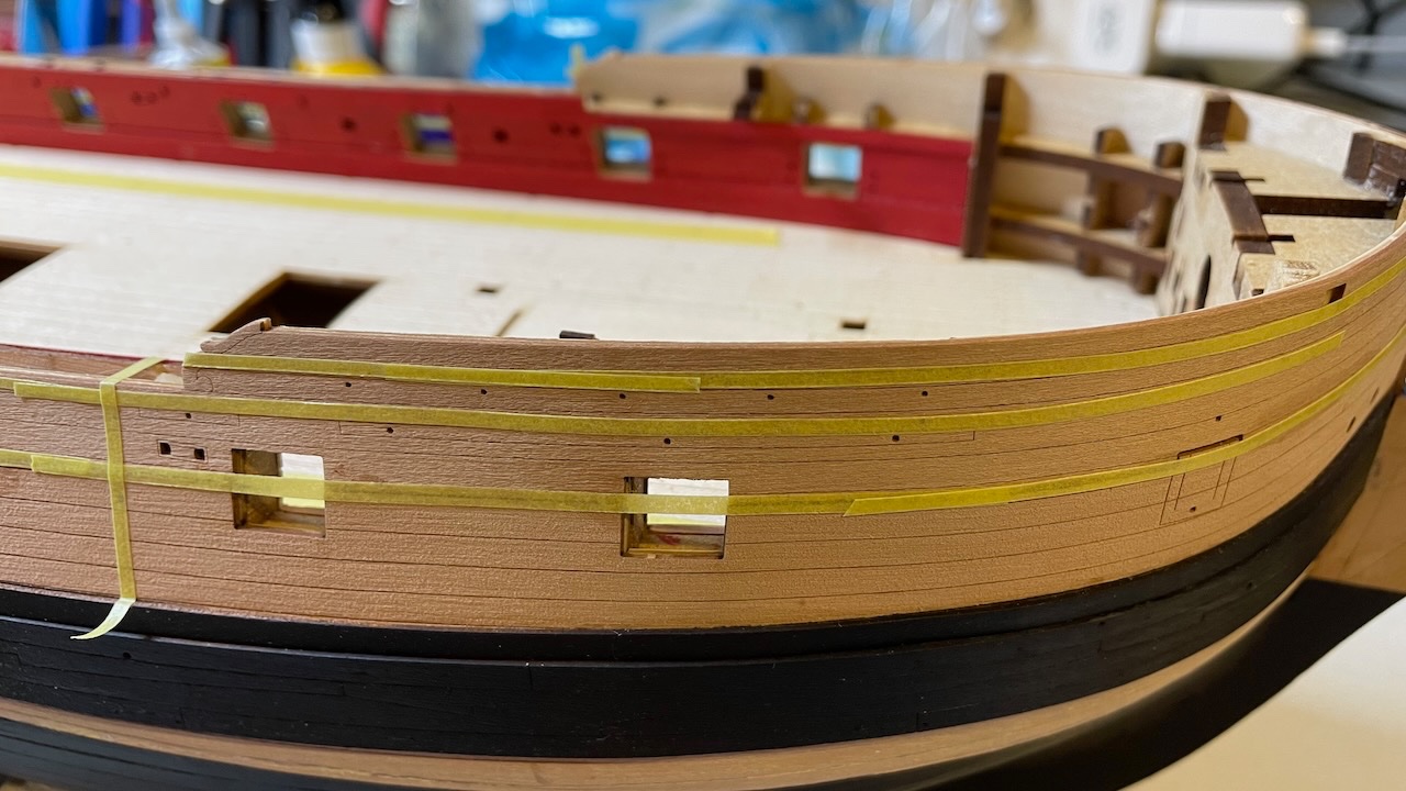
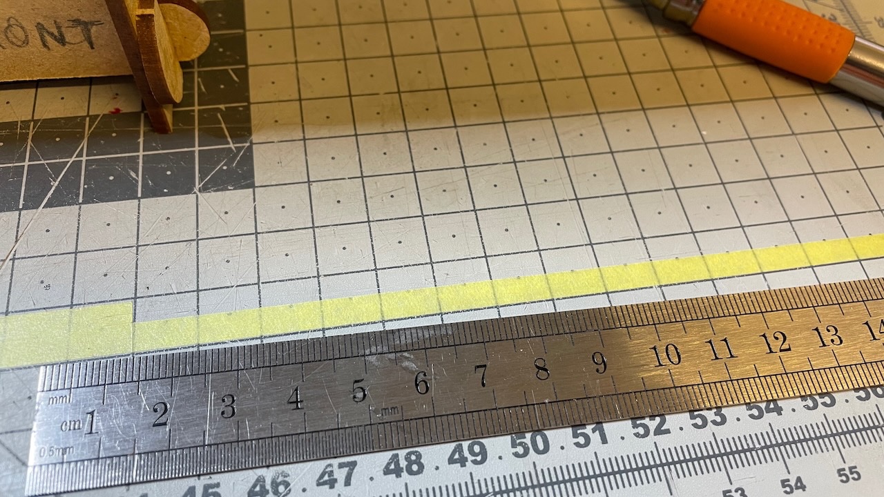
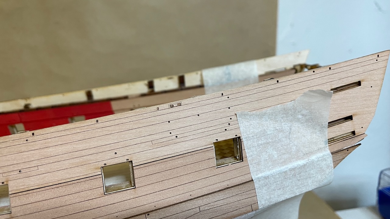
Build day 35: 4hrs / Total 73 hours Today I spent about 4 hours on - masking and aligning the rails, - varnishing the hull, - painting, - gluing the rails. Photo 298: Sliced approx. 2mm wide strips from my masking tape for covering the areas where the rails will sit, to prevent from varnish.
- 426 replies
-
- 1
-
-
- Vanguard Models
- Sphinx
- (and 1 more)
-
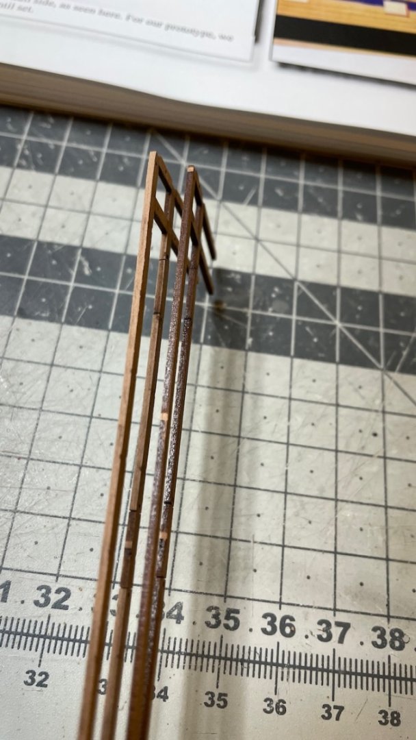
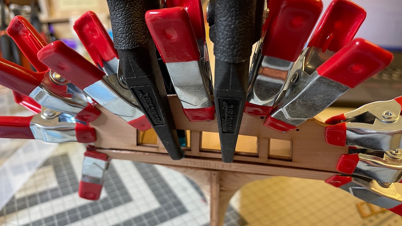
While they are drying, I prepare the other ones (that need no prior bending). I used my Dspiae sanding stick to remove laser char as good as I can, focusing mainly on more visible areas. I also use clamps to help strengthen against sanding stick strokes. Photo 294: Parts carefully removed from the wooden sheet. Photo 295: Here is a comparison, chars removed vs not removed. Photos 296-297: Use of clamps and sanding stick.

- 426 replies
-
- 4
-
-
- Vanguard Models
- Sphinx
- (and 1 more)
-
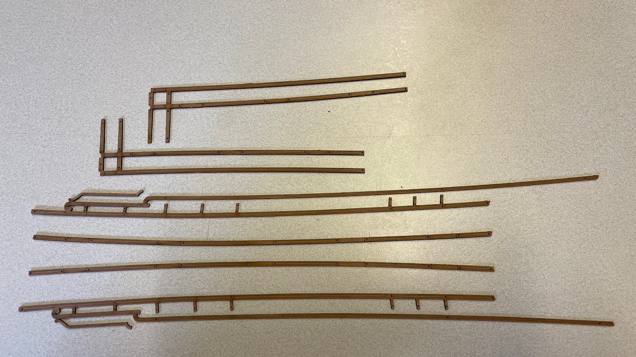
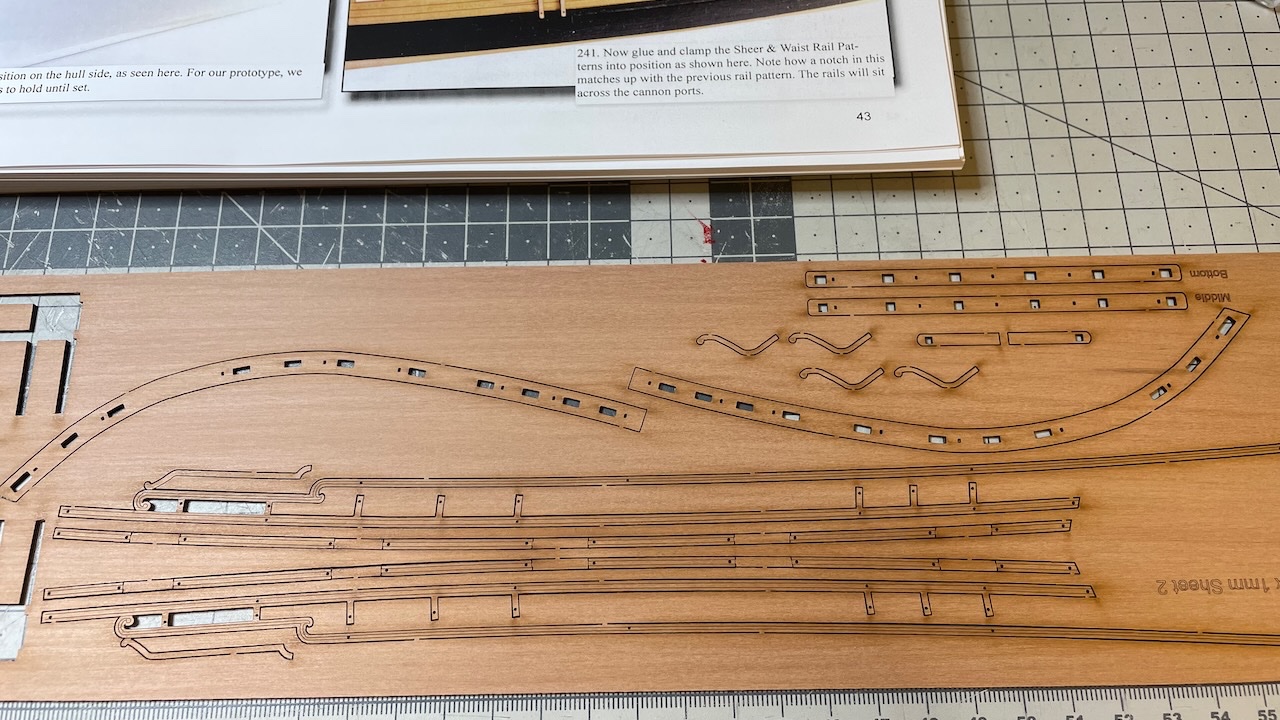
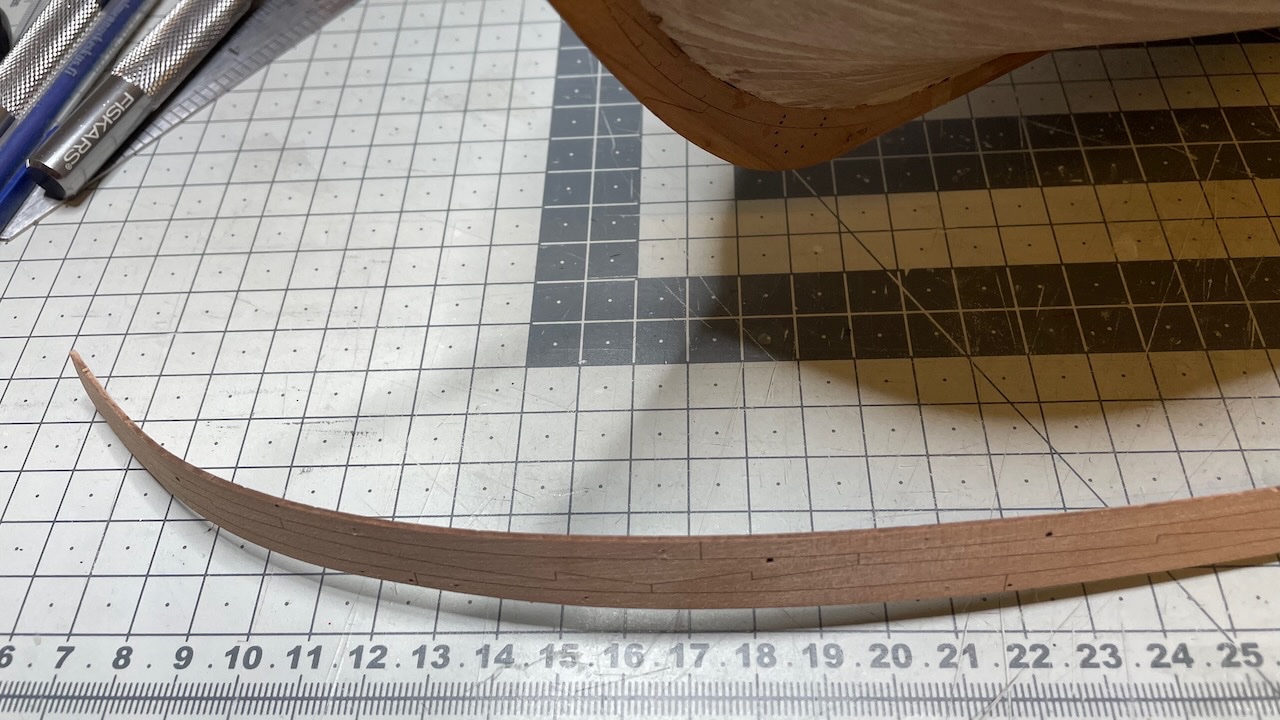
Build day 34: 2hrs / Total 69 hours Today I spent roughly 2 hours on preparing rail patterns. These are among the most delicate and fragile parts. Photos 292-293: Sheer and Waist Rail patterns, removed, soaked (for 20 mins) and pegged on location, waiting to dry for at least 24 hours. As instructed, I used scrap planking strips to apply even pressure and prevent from being damaged.
- 426 replies
-
- 2
-
-
- Vanguard Models
- Sphinx
- (and 1 more)
-
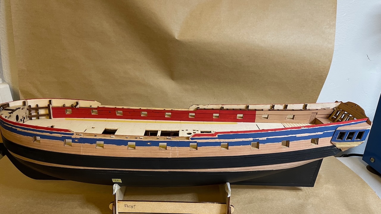
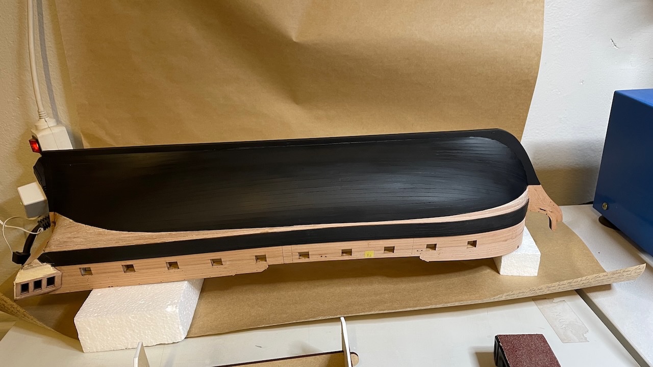
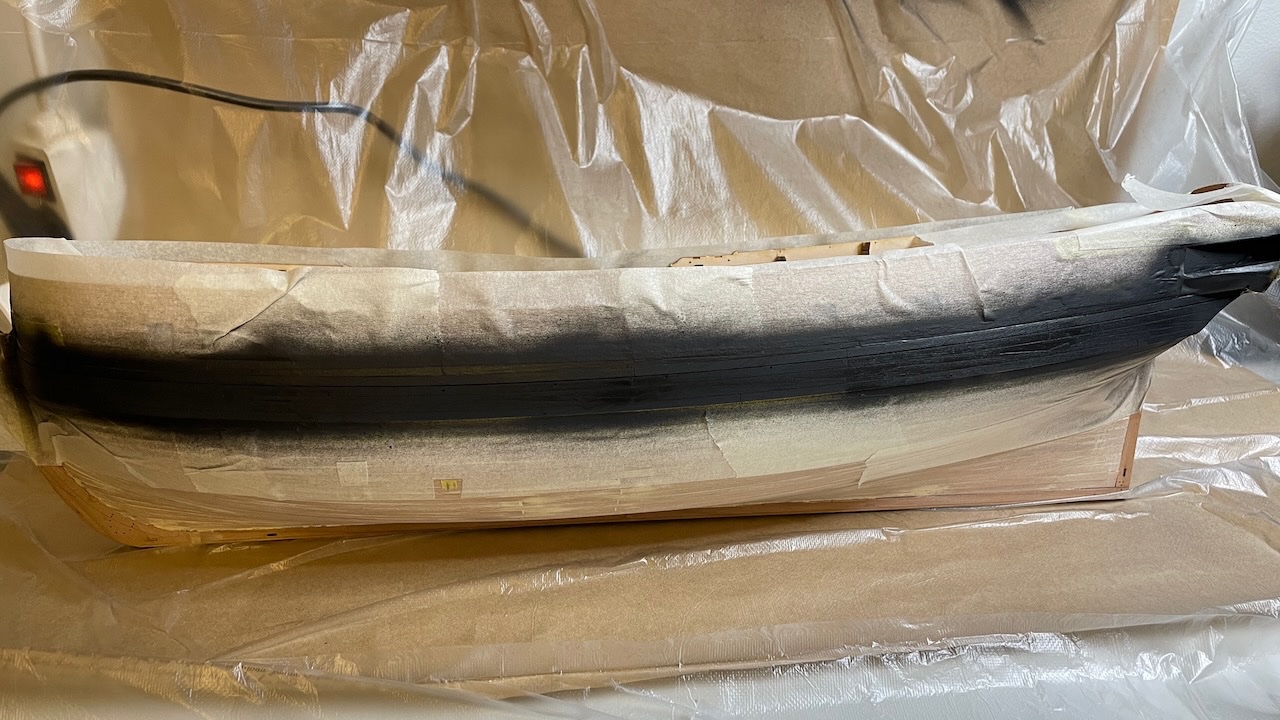
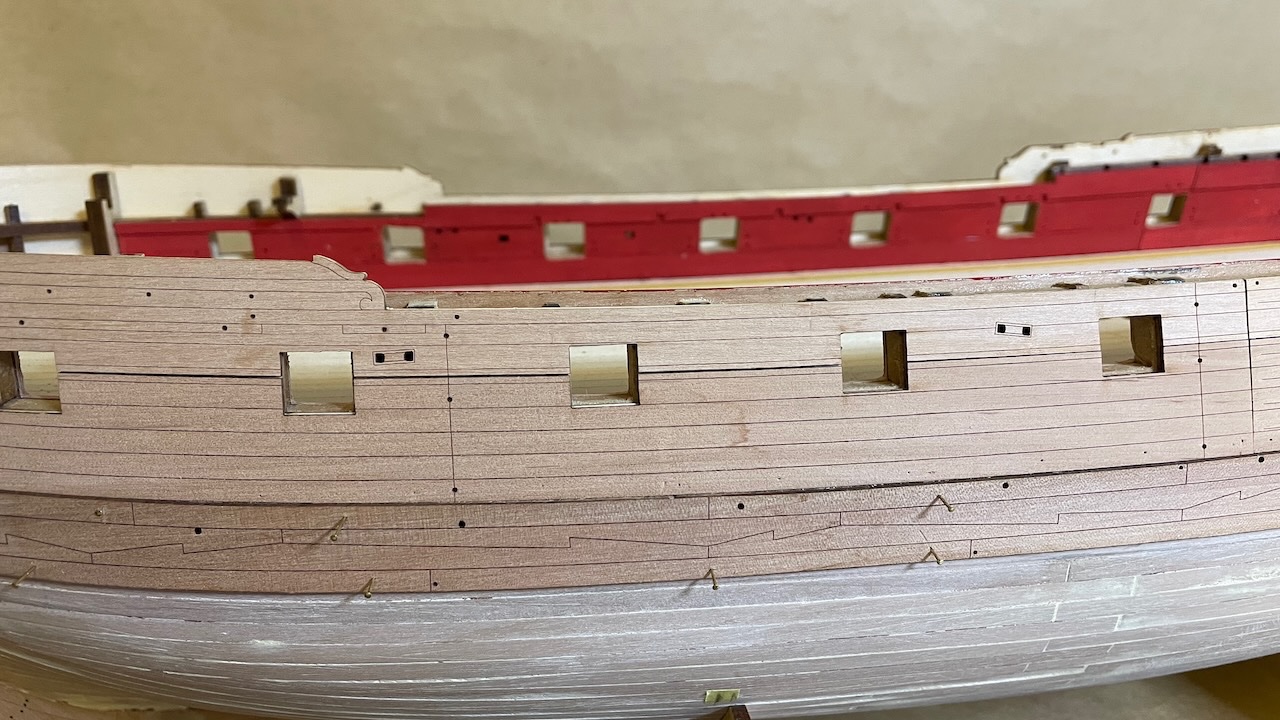
Photo 291: A waterline can be painted in any color, as long as it is black 😆. Well, I thought over this a lot and finally chose black instead of white. As I wrote earlier I like slightly visible planking patterns rather than a completely smooth surface, as it gives a more hand made like look. In my opinion black would suit better than white in this case. I am happy with the result.
- 426 replies
-
- 3
-
-
- Vanguard Models
- Sphinx
- (and 1 more)
-
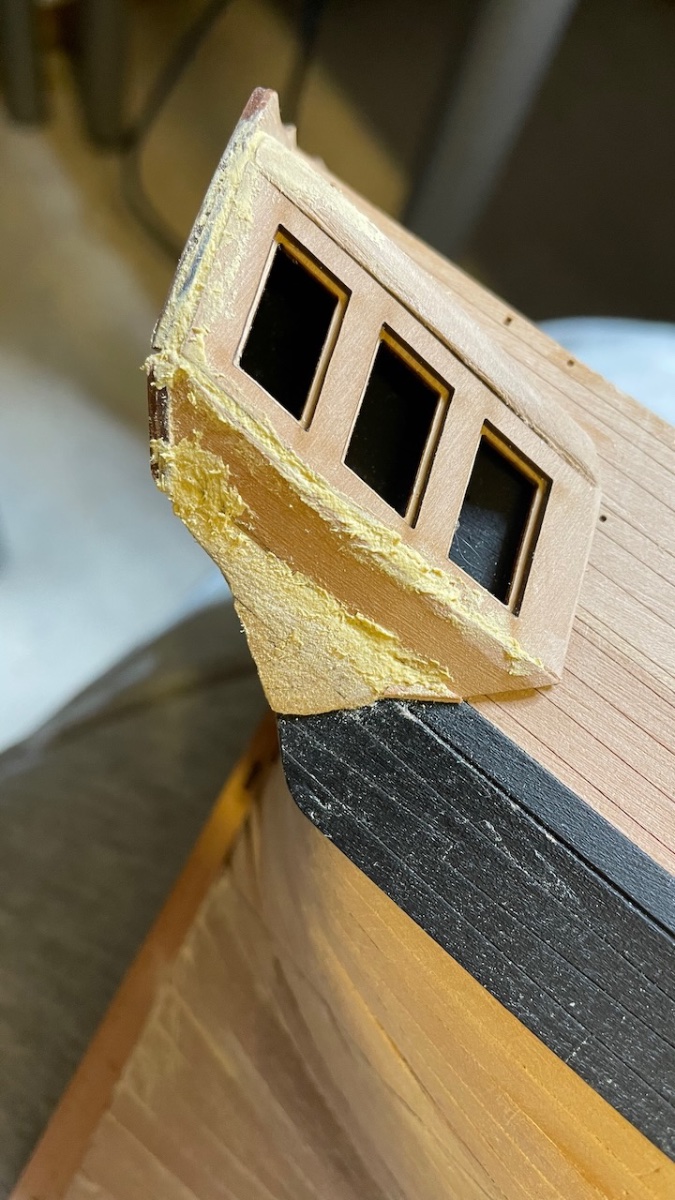
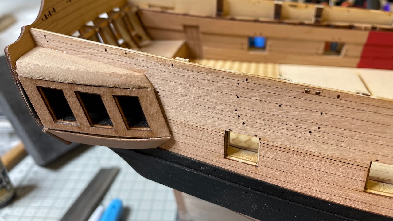
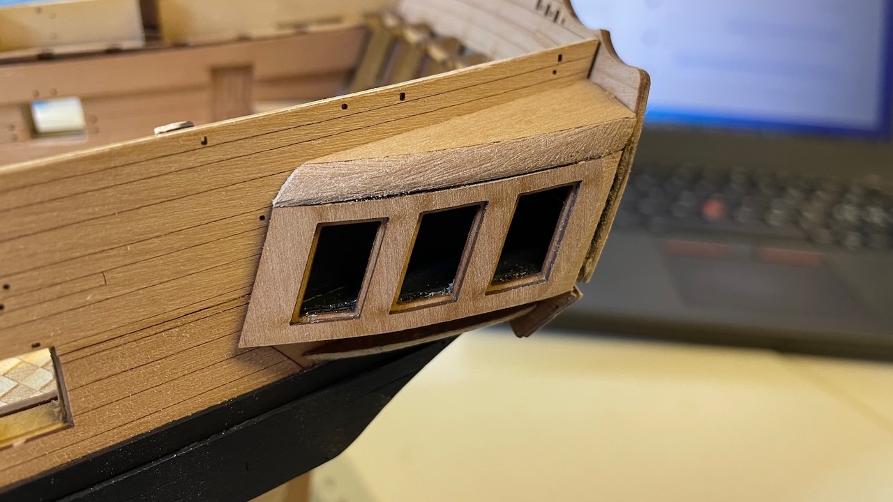
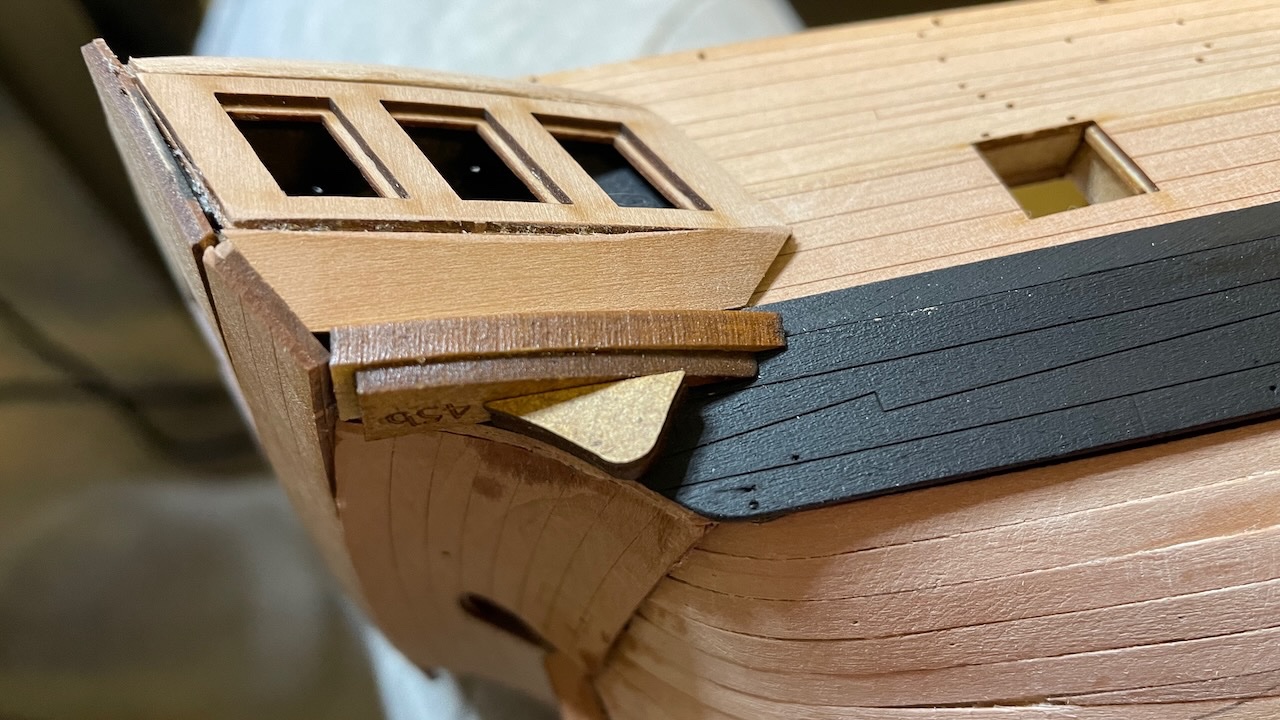
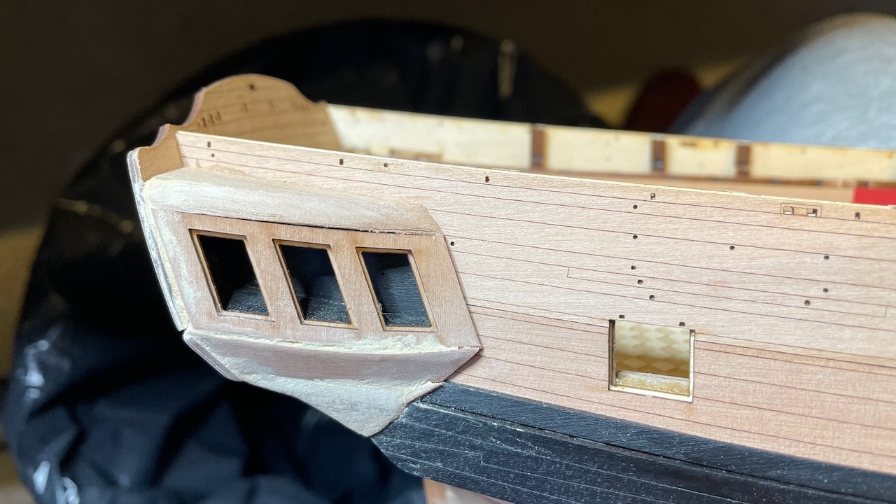
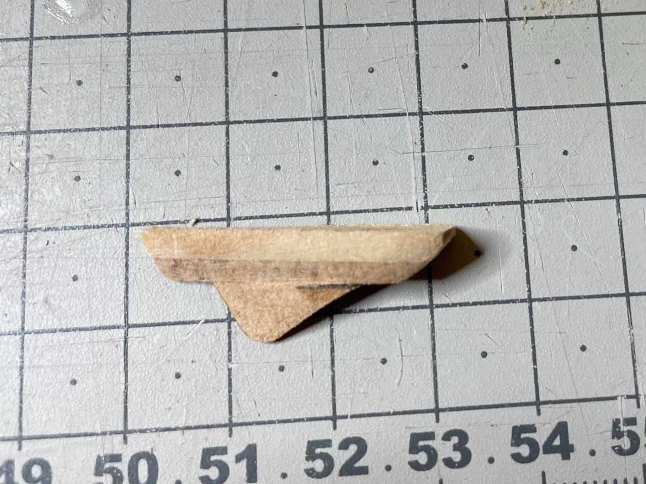
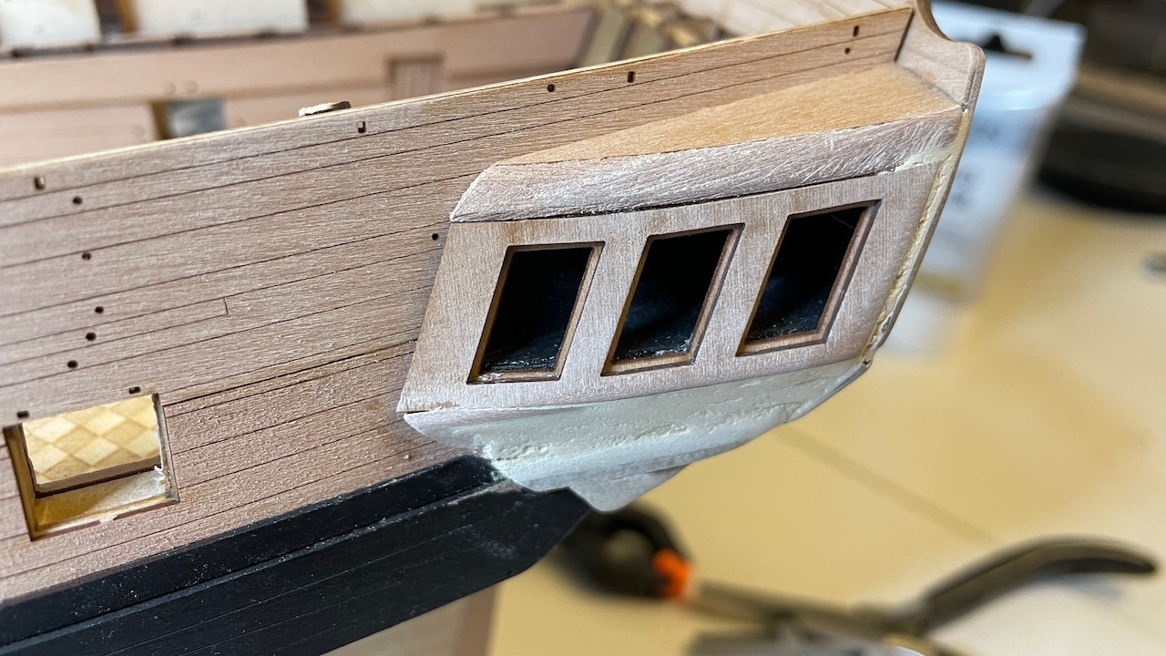
Several photos showing the progress of Quarter Gallery windows installation. Here there is quite a bit of rasping and bevelling of the parts. It mostly went smoothly but at some parts I used wood filler to achieve smooth transition. At this stage sanding is not complete yet. Most of this section will remain under paint and decoration. Photo 283: Bevelling of the roof part. Photos 284-285: Windows on both sides. Photo 286: Lower finishing patterns, made up of three parts, dry fitted. This will substantial amount of rasping and sanding to get to shape. Photo 287: Looks about like this after shaping Photos 288-290: Wood fillers to cover impurities. I will sand them more later.


- 426 replies
-
- 5
-
-
- Vanguard Models
- Sphinx
- (and 1 more)
-
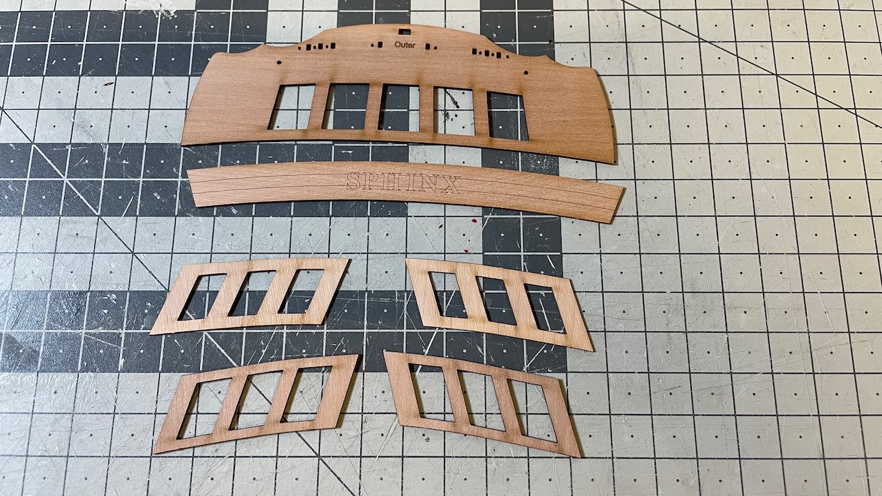
Build day 33: 3.5hrs / Total 67 hours Photo 282: Stern upper counter pattern (outer) and Stern fascia (outer)
- 426 replies
-
- 1
-
-
- Vanguard Models
- Sphinx
- (and 1 more)
-
Photo 281: Paint dried, masking tapes removed. Looking good enough.
- 426 replies
-
- 5
-
-
- Vanguard Models
- Sphinx
- (and 1 more)
-
Photo 280: Preparing the next parts while the paint is drying. Now coffee time!
- 426 replies
-
- 3
-
-
- Vanguard Models
- Sphinx
- (and 1 more)
-
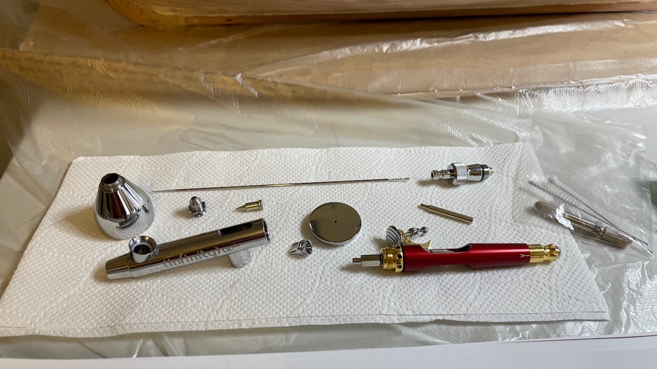
Photo 279: Cleaning the airbrush is crucial after each paint job
- 426 replies
-
- 1
-
-
- Vanguard Models
- Sphinx
- (and 1 more)
-
Photos 277-278: Masking and painting with airbrush.
- 426 replies
-
- 2
-
-
- Vanguard Models
- Sphinx
- (and 1 more)
-
Photos 274-276: Quarter gallery patterns bevelled as instructed and glued. First photo showing an example of before and after bevelling. Used another piece as spacer while the glue dries.
- 426 replies
-
- 2
-
-
- Vanguard Models
- Sphinx
- (and 1 more)
-
Photos 272-273: Stern counter (inner) and Sten facia (inner). Yes, there is a visible gap but it will be hidden later after outer patterns and with trim strip.
- 426 replies
-
- 3
-
-
- Vanguard Models
- Sphinx
- (and 1 more)
-
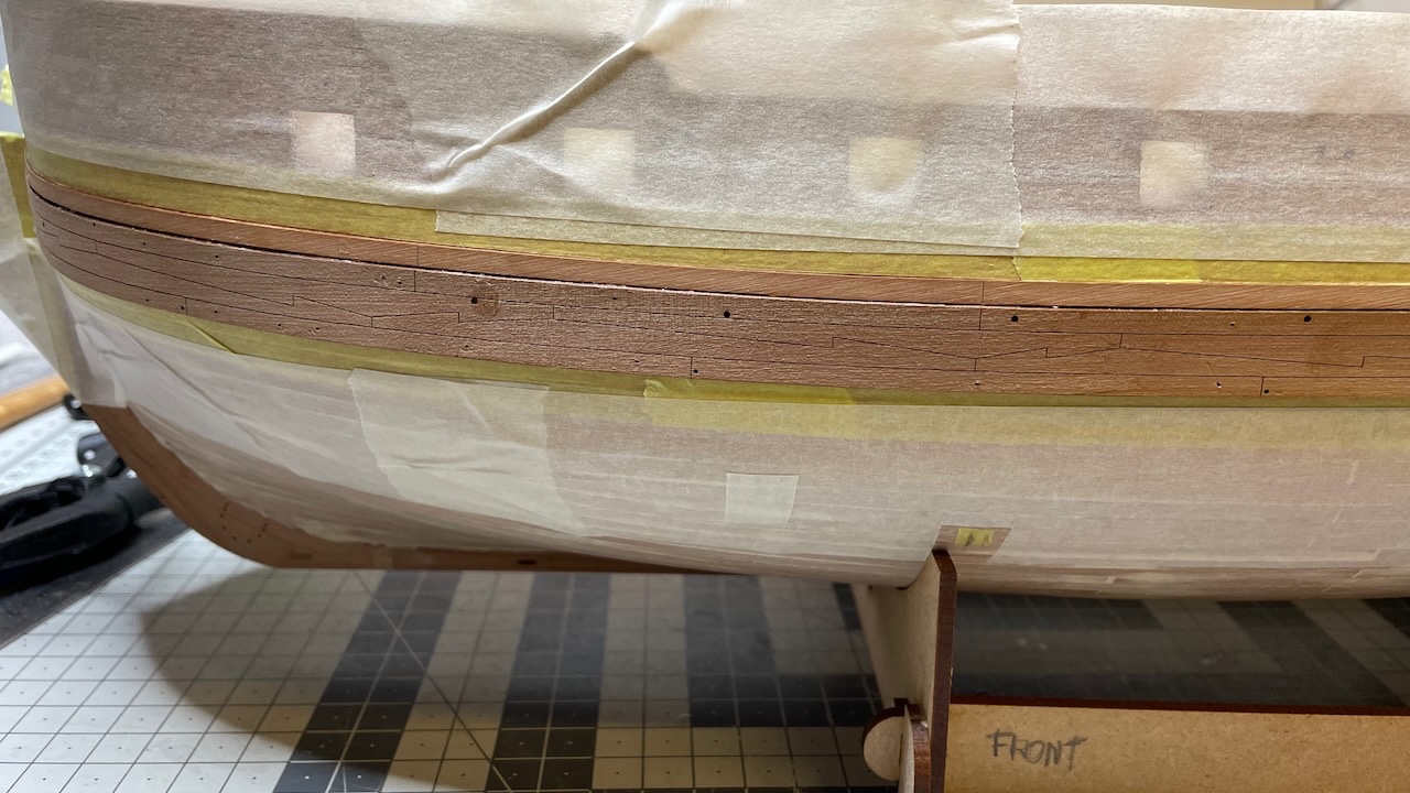
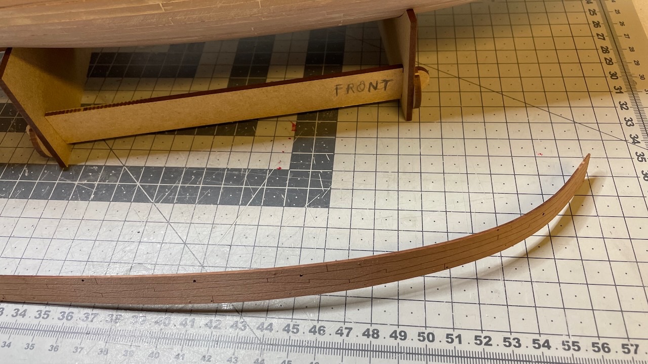
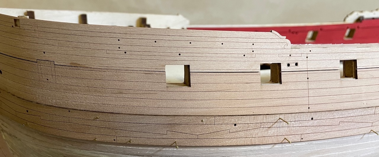
Build day 32: 2.5hrs / Total 63.5 hours Photos 270-271: Main Whale patterns dried nicely to shape. Now it is time to glue them and strakes above them in place.
- 426 replies
-
- 3
-
-
- Vanguard Models
- Sphinx
- (and 1 more)
-
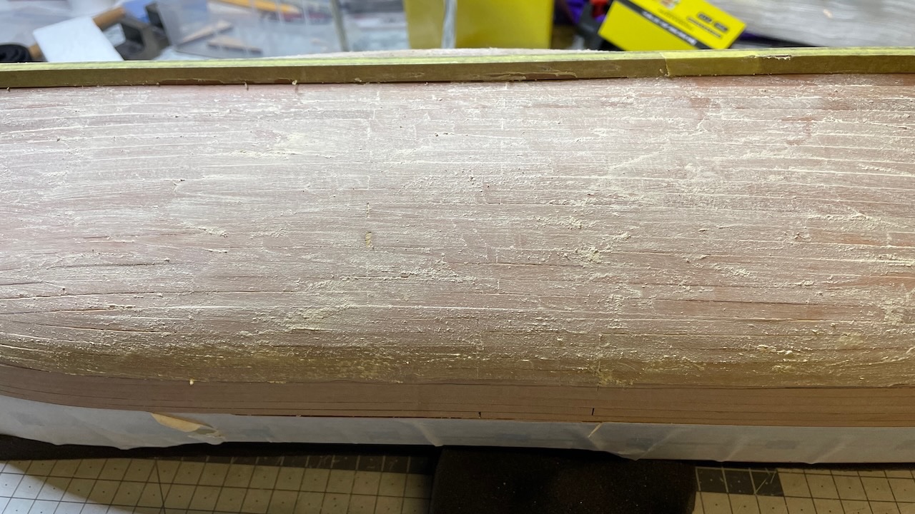
Build Day 31: 1hr / Total 62 hours After sanding, one layer of wood filling looks good enough to me. I prefer the wood plank patterns exposing a little under the paint than having a perfectly smooth painted hull. To me it gives a more handmade look than ready made hull. It is a question of taste. Photos 267-269: Main whale patterns soaked in hot water for 30mins and pinned temporarily in place to dry and get the shape. These are thicker than the parts we did the same procedure earlier (1mm vs 0.8mm) therefore 30 mins is the minimum you should keep them in water. It was enough to soak only the front section where it will bend. Now it will rest at least 24 hours.
- 426 replies
-
- 5
-
-
- Vanguard Models
- Sphinx
- (and 1 more)
-
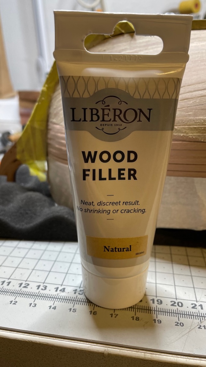
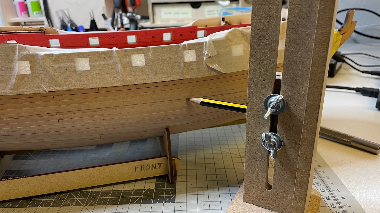
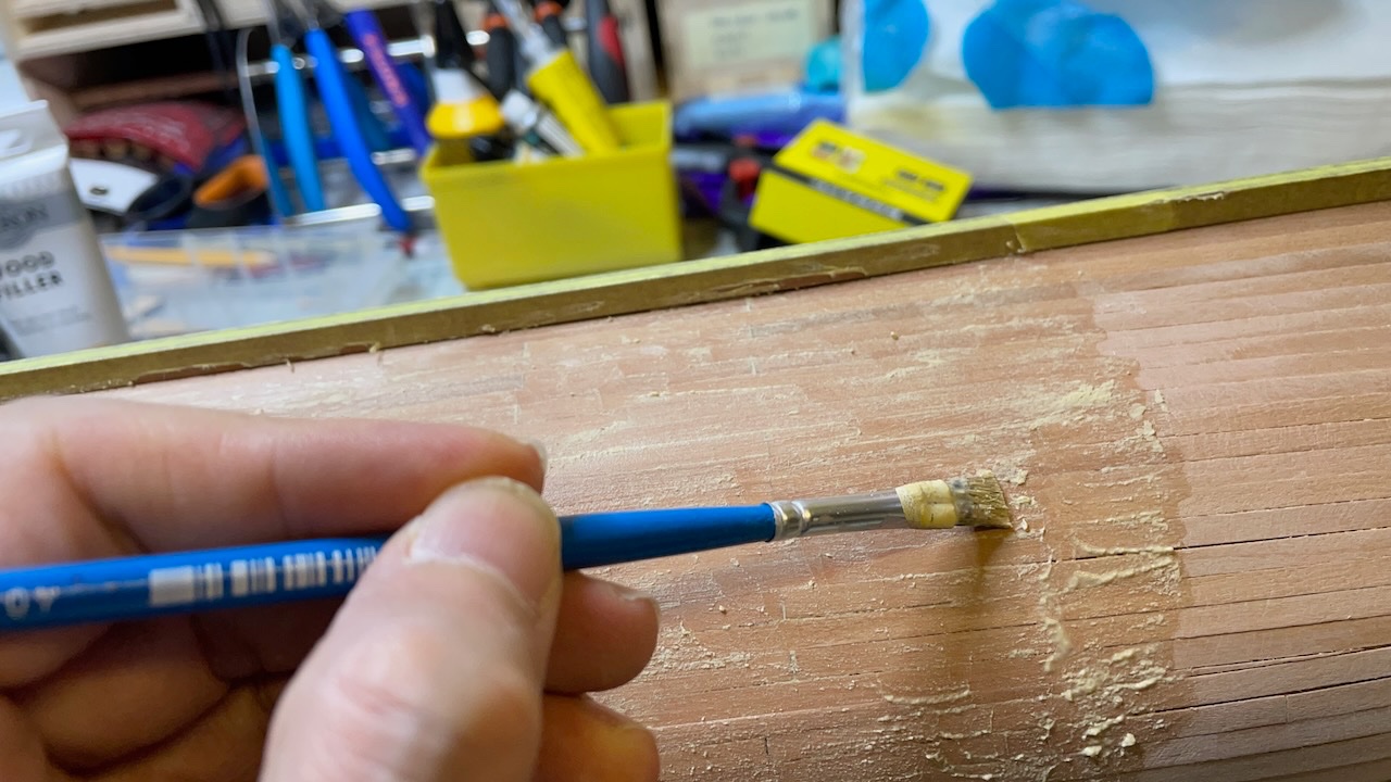
Photos 263-266: Preparing to smoothen below the waterline. I used diluted Liberon Natural Wood Filler applied with a brush. This is now the first round, waiting for the filler to dry before fine sanding. Waterline marker is from Hobbyzone.

- 426 replies
-
- 5
-
-
- Vanguard Models
- Sphinx
- (and 1 more)
-
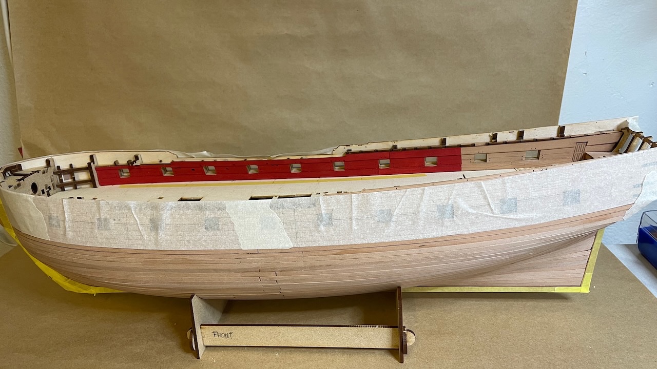
Build Day 30: 1,5 hr / Total 61,5 hours Photos 261-262 Removing jigs and nubs which are not needed anymore. Hull is now ready for sanding. Engravings covered with masking tape to prevent accidental sanding. By the way this brings me to step 185 in the instructions.

- 426 replies
-
- 3
-
-
- Vanguard Models
- Sphinx
- (and 1 more)