aydingocer
-
Posts
858 -
Joined
-
Last visited
Content Type
Profiles
Forums
Gallery
Events
Everything posted by aydingocer
-
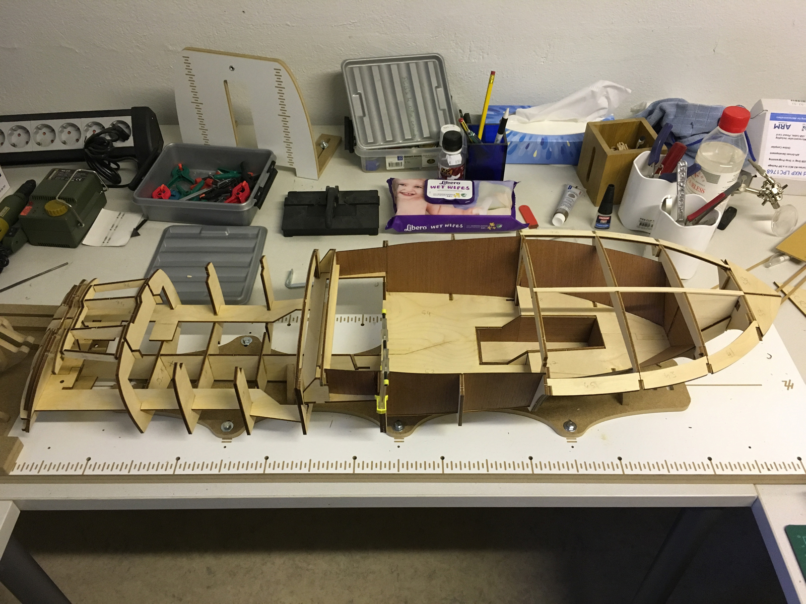
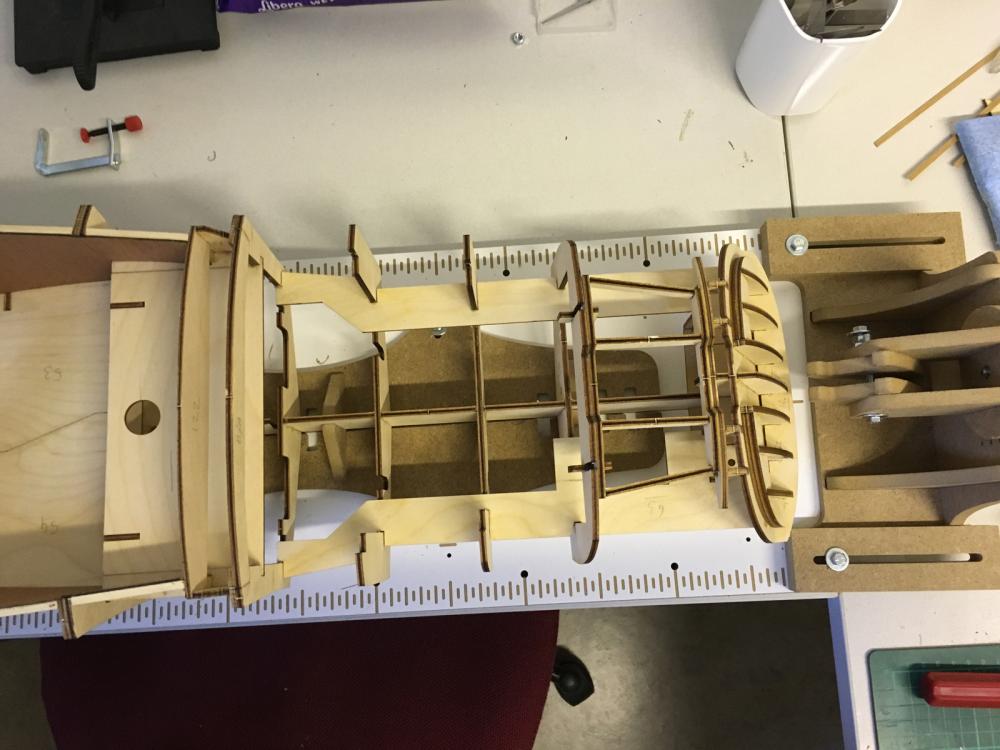
 END OF BUILD DAY 4. 1,5 hours today. 15,5 hours into build in total. This is the status at the end of DAY4 .Thanks for watching.
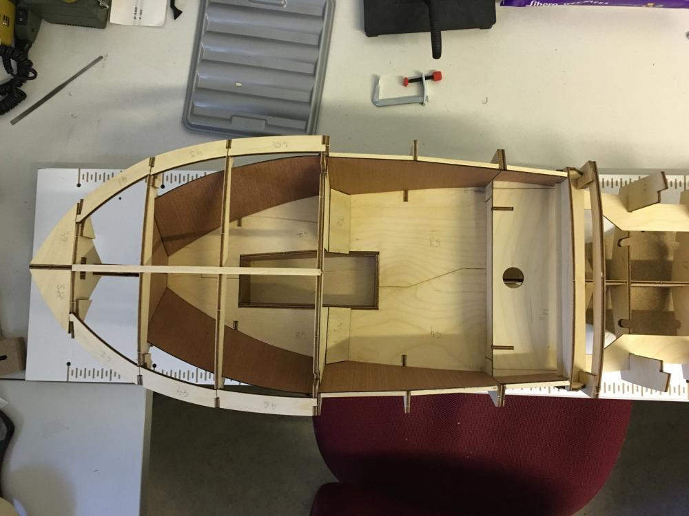
- 414 replies
-
- 5
-

-
- riva aquarama
- amati
- (and 2 more)
-
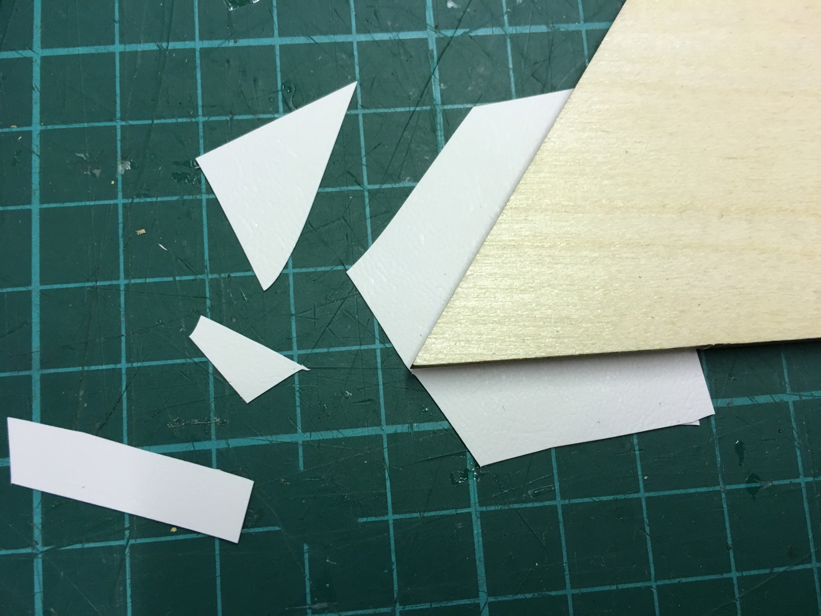
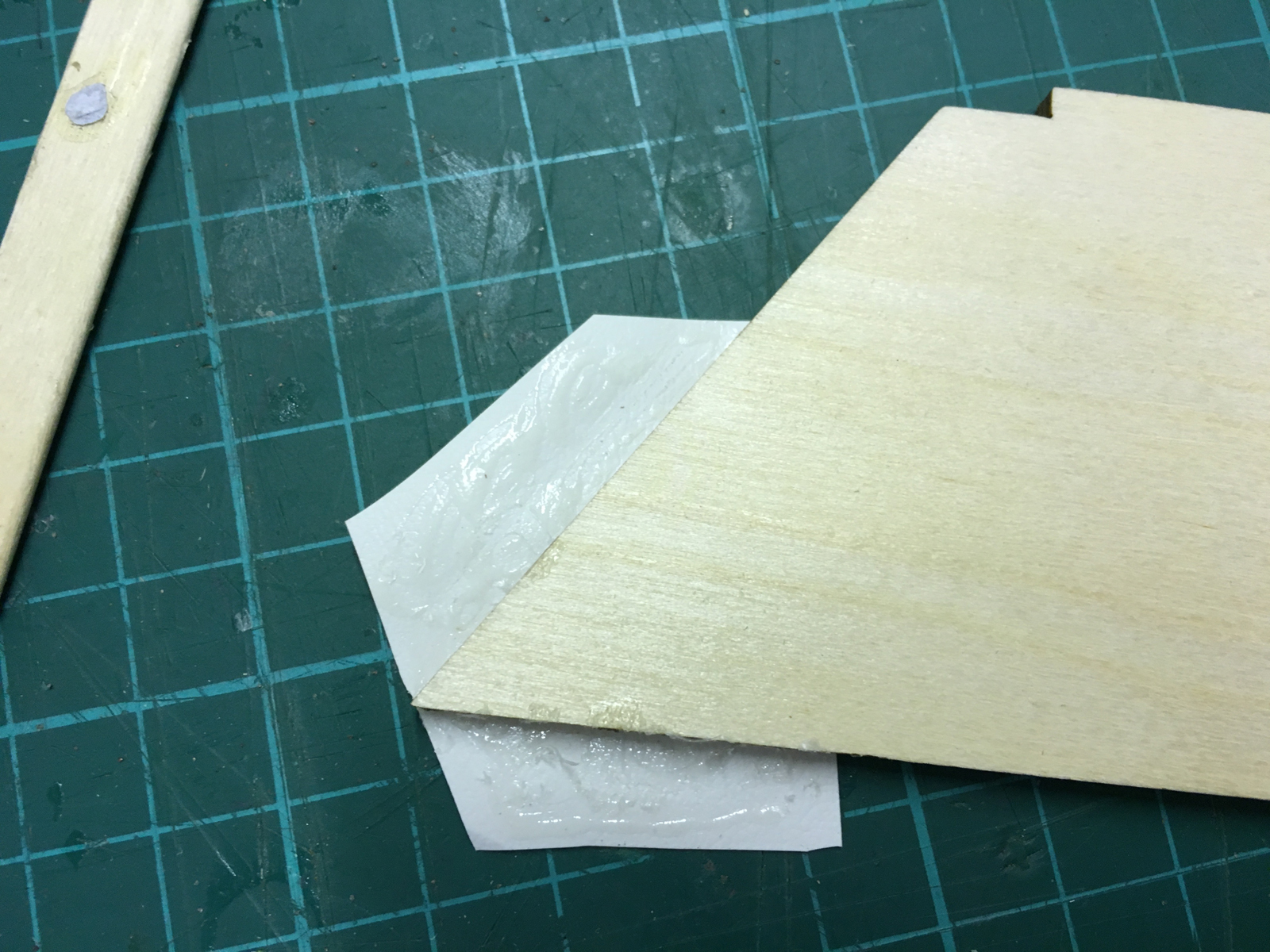
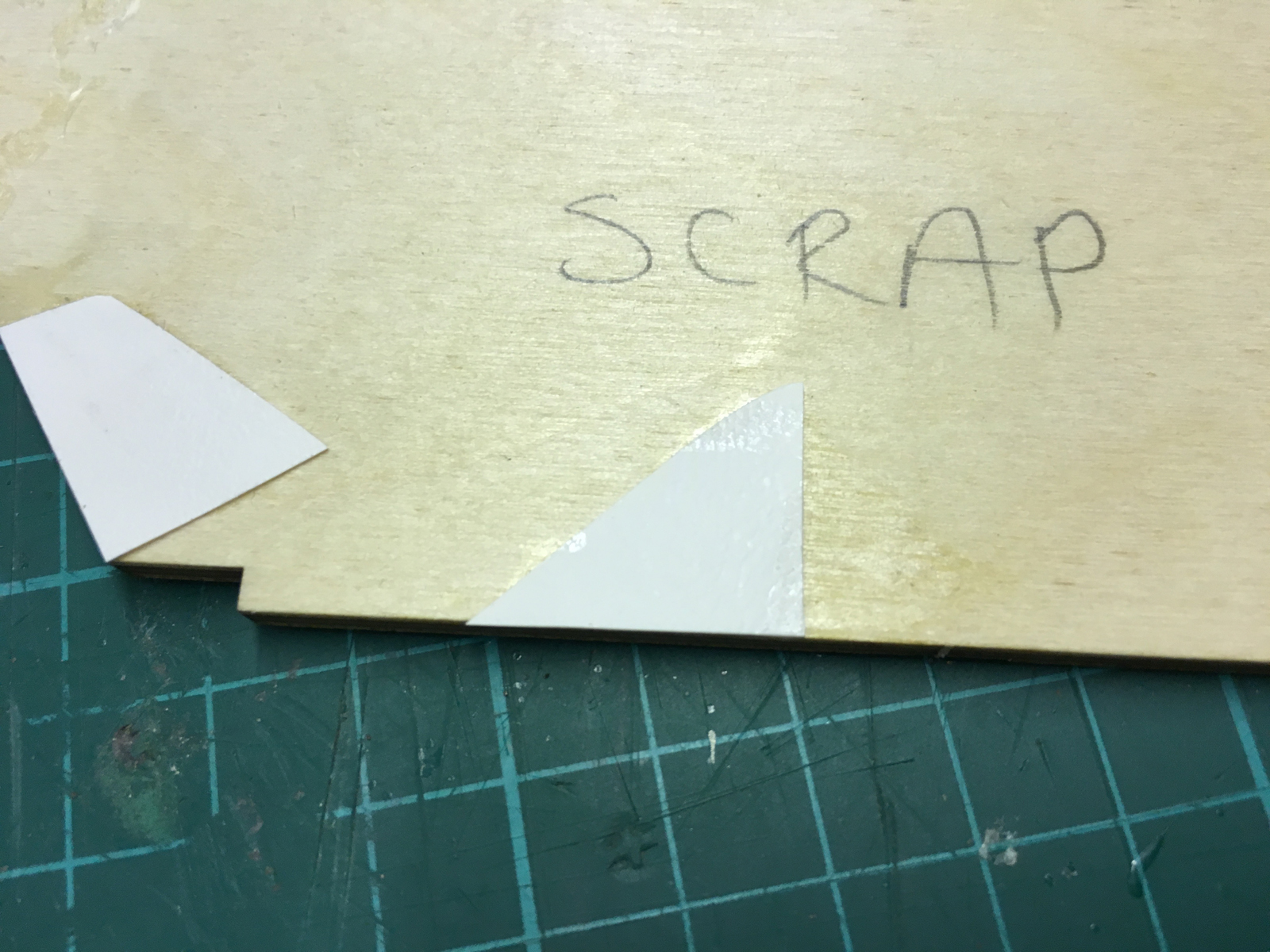
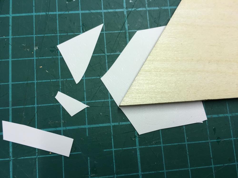
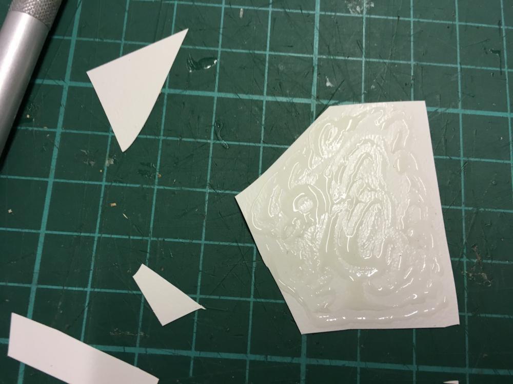
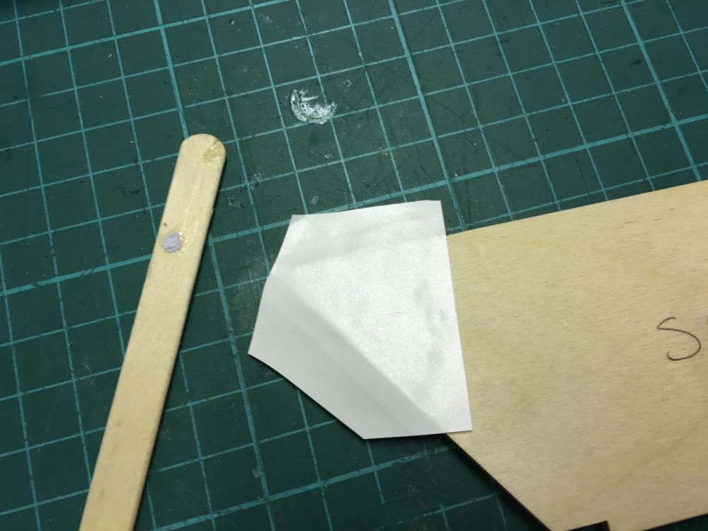
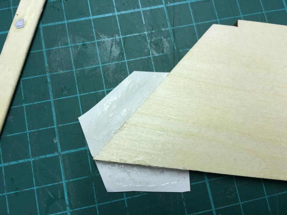
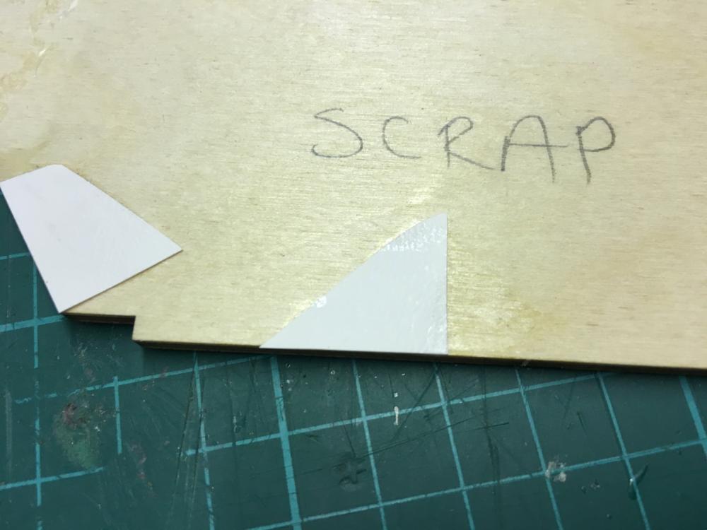
And now I turn the page of the manual only to find out that I have to stop for today: Looks like it is time to apply some lacquer which I wasn’t expecting to come this quick. Well, actually the instructions are not calling for it just yet. According to the manual it is time to apply the “leather-like material” (that’s what the manufacturer keeps calling it throughout the manual) inside the cockpit. It sounds however wiser to apply the lacquer inside first in order to eliminate the risk of spilling lacquer on the upholstery. I saw in another build log in another forum that the builder applied water proof lacquer all around inside, I think that’s what I will do. So I’ll go and buy a boat grade lacquer tomorrow. I also checked this “leather-like” material. It is totally plastic and feels a bit tricky to fold in the corners. I decided to try on a piece of scrap and first results was not promising: Cut a test piece: Apply glue (trying with UHU Hart just out of curiosity): Put on the plywood, swipe with a piece of stick applying pressure: However it didn’t seem to work. There came air bubbles and eventually the glue came loose: Then I tried with CA (super glue), which seemed to work well, except that the residues left stains here and there. Have to be very careful if I choose to use CA. . It seems very tricky and make-no-mistake task to successfully apply the upholstery to the entire cockpit. Right now I think this will be my plan: - replace the leather-like plastic with thin faux leather sheet. It would look more realistic and be easier to work with. - cut identical pieces from a very thin veneer (or from acetate sheet) using the plan sheets as guide - glue the faux leather peacefully on these pieces - and finally glue them in their places on the cockpit Or any suggestions? So, next, I will lacquer the interior and move on to the next task until I do the shopping above.
- 414 replies
-
- 6
-
-
- riva aquarama
- amati
- (and 2 more)
-
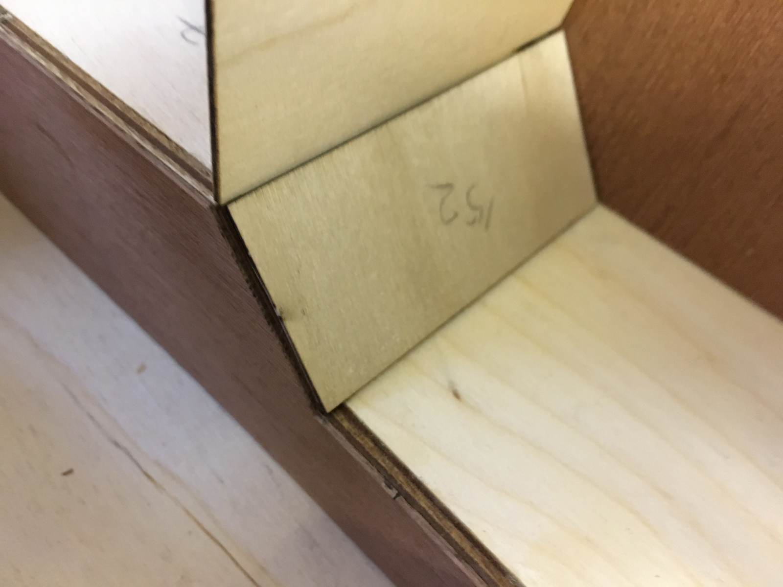
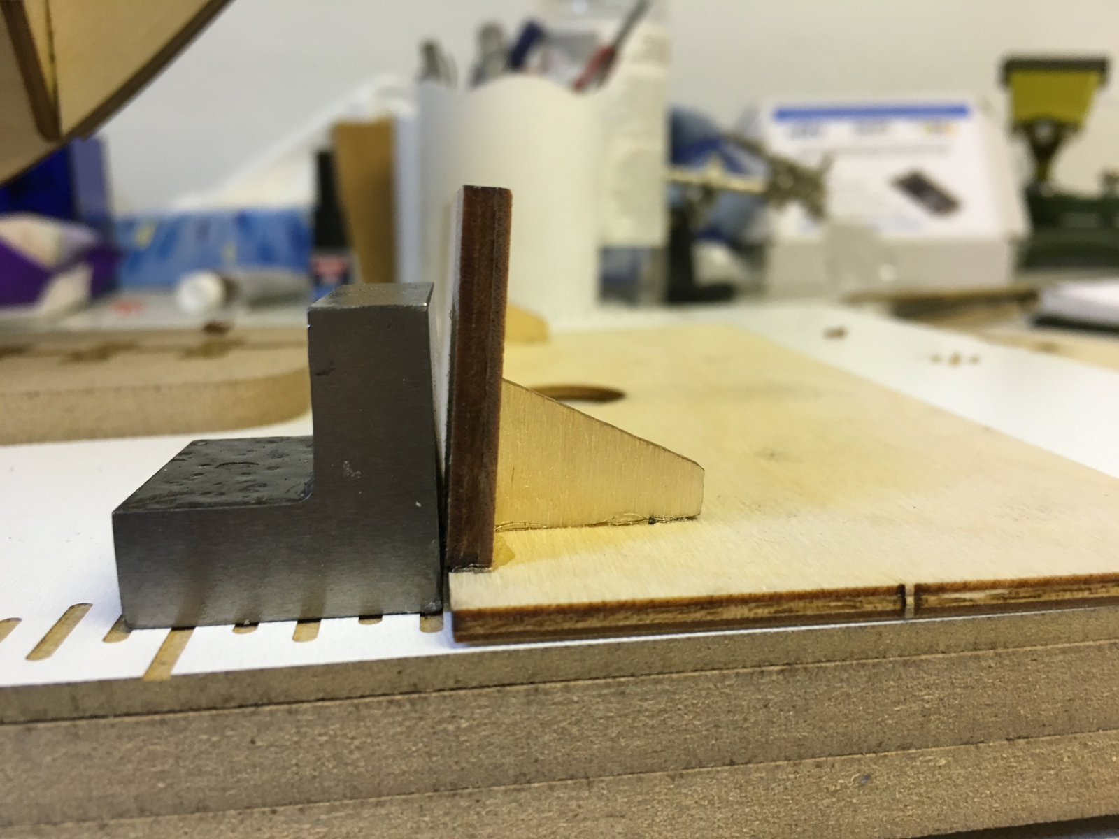
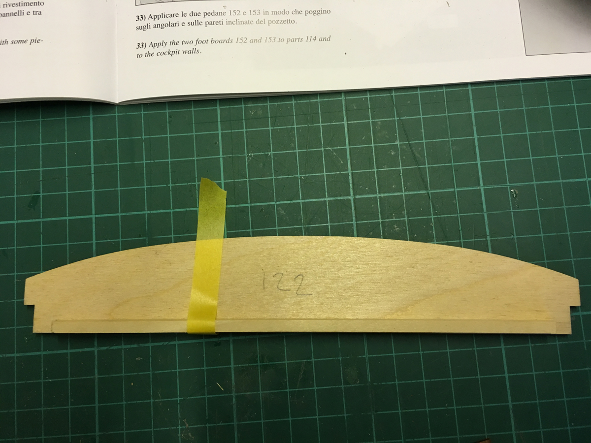
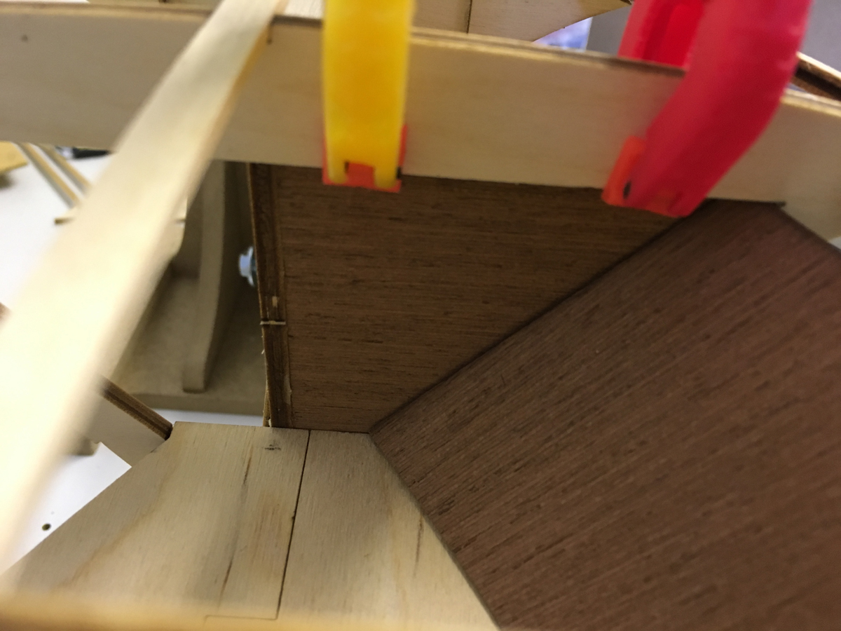
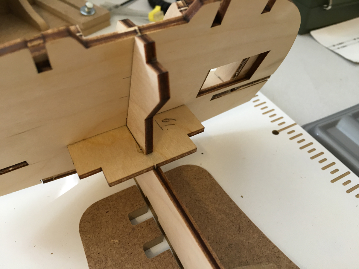
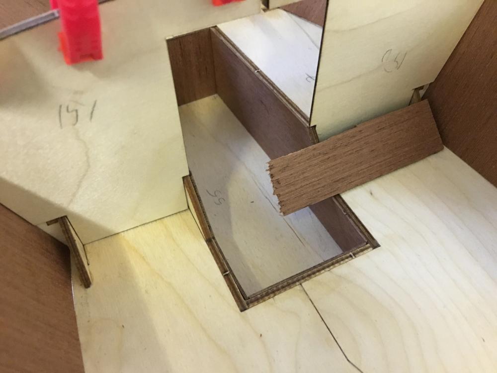
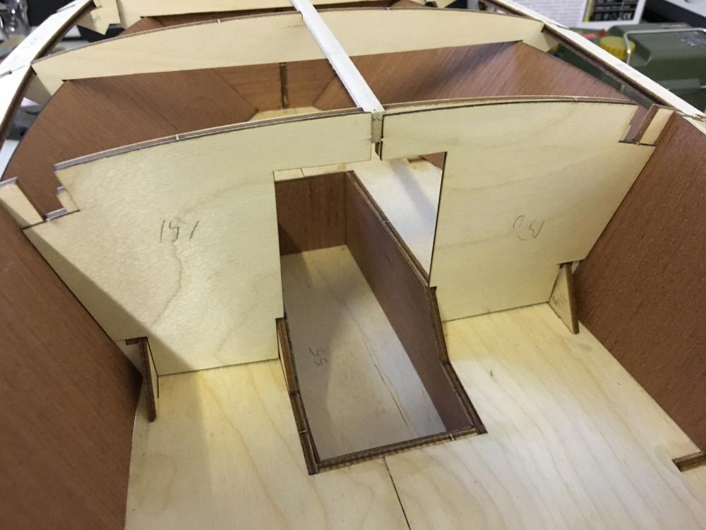
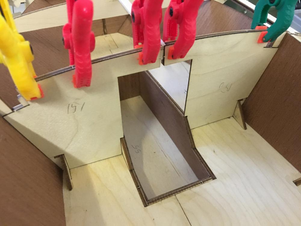
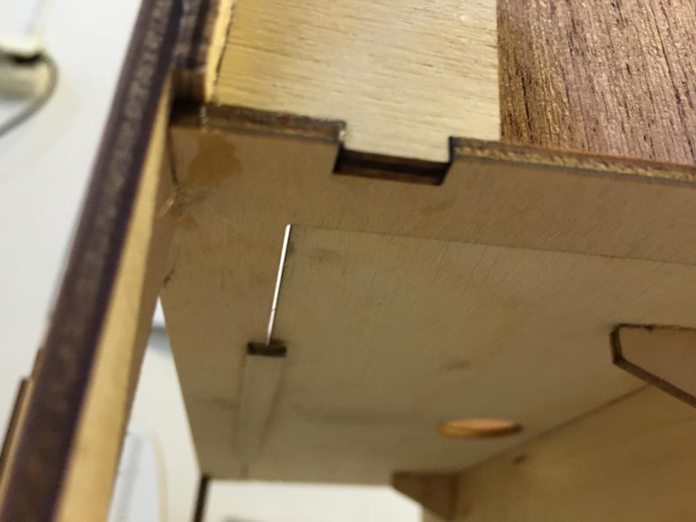
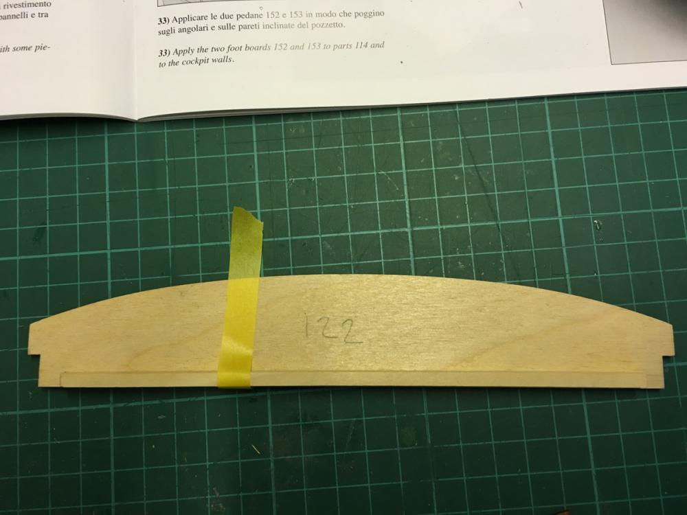
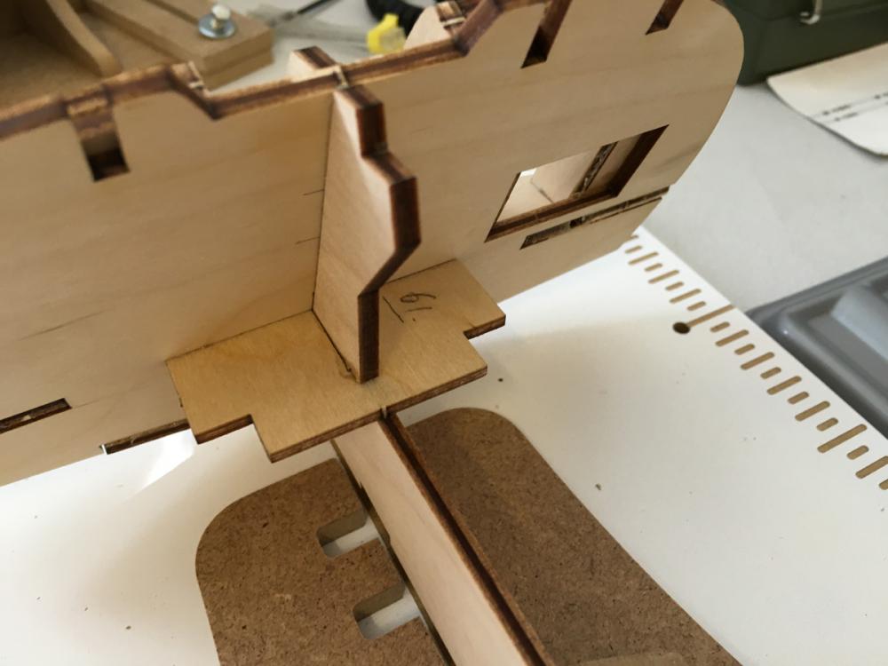
Parts 152 and 153 are the footrests which will be glued inclined. I used a piece of scrap wood (no glue) ensure that the triangular parts which will hold them dry at identical angle. According to the specs the footrests are not flush with the mahogany plank (in this photo it is the plank on the left side. Similar thing is for the other footrest). They stop at the end of the plywood allowing the edge of the mahogany plank to show.

- 414 replies
-
- 4
-
-
- riva aquarama
- amati
- (and 2 more)
-
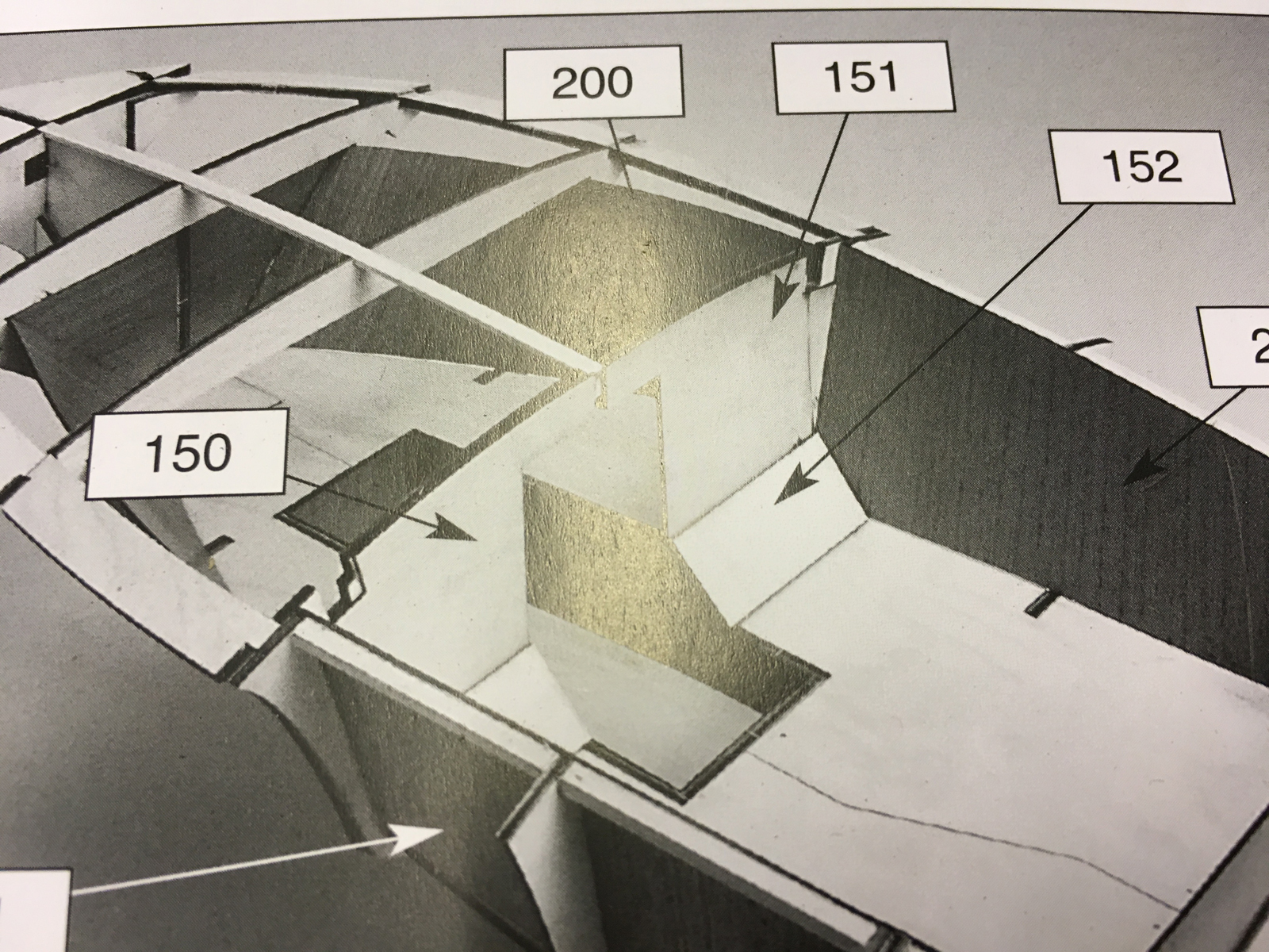
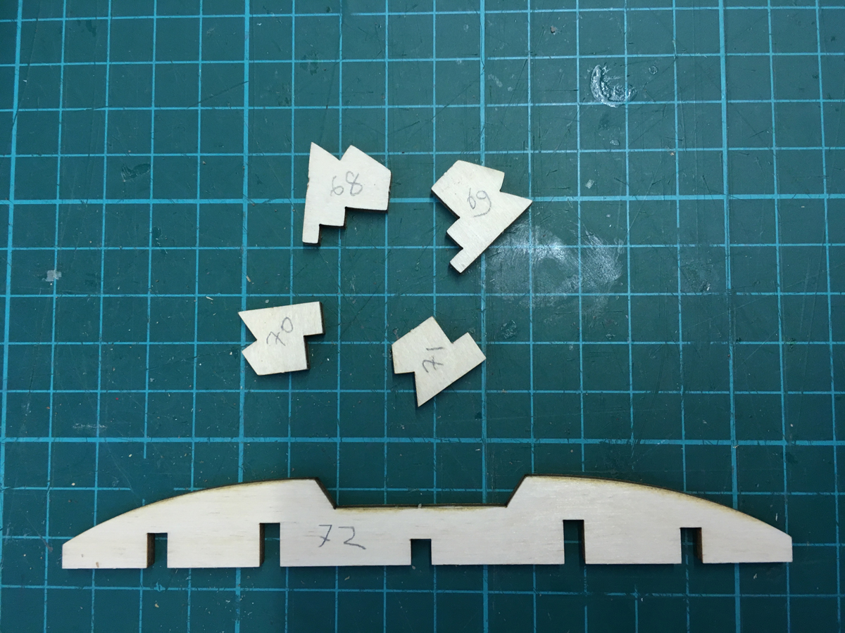
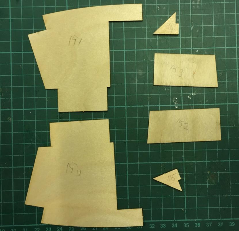
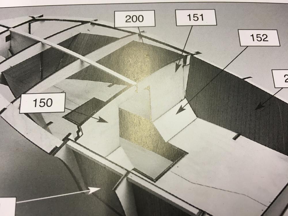
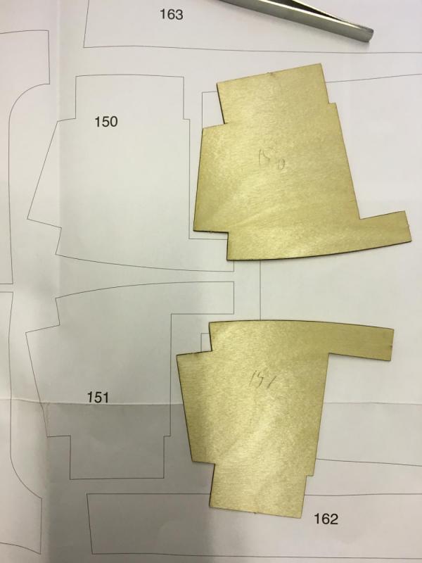
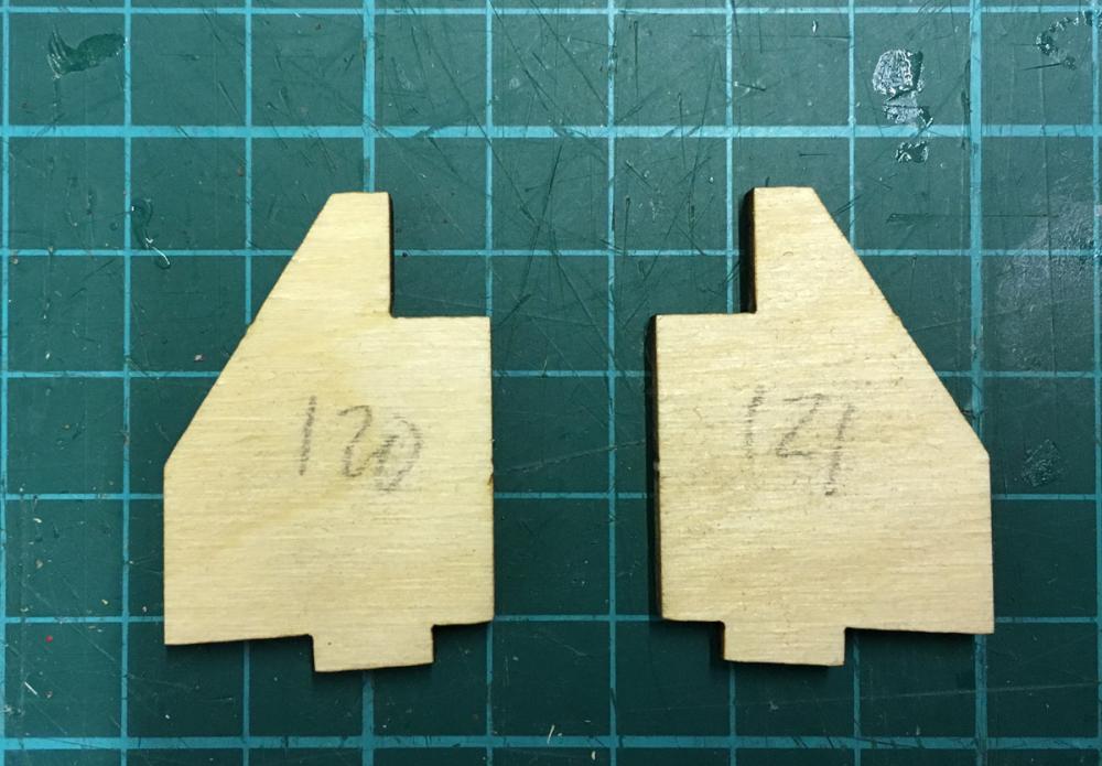
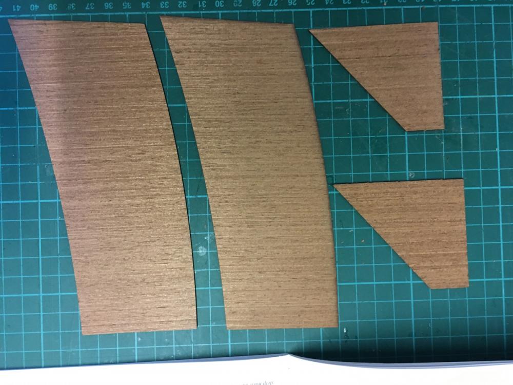
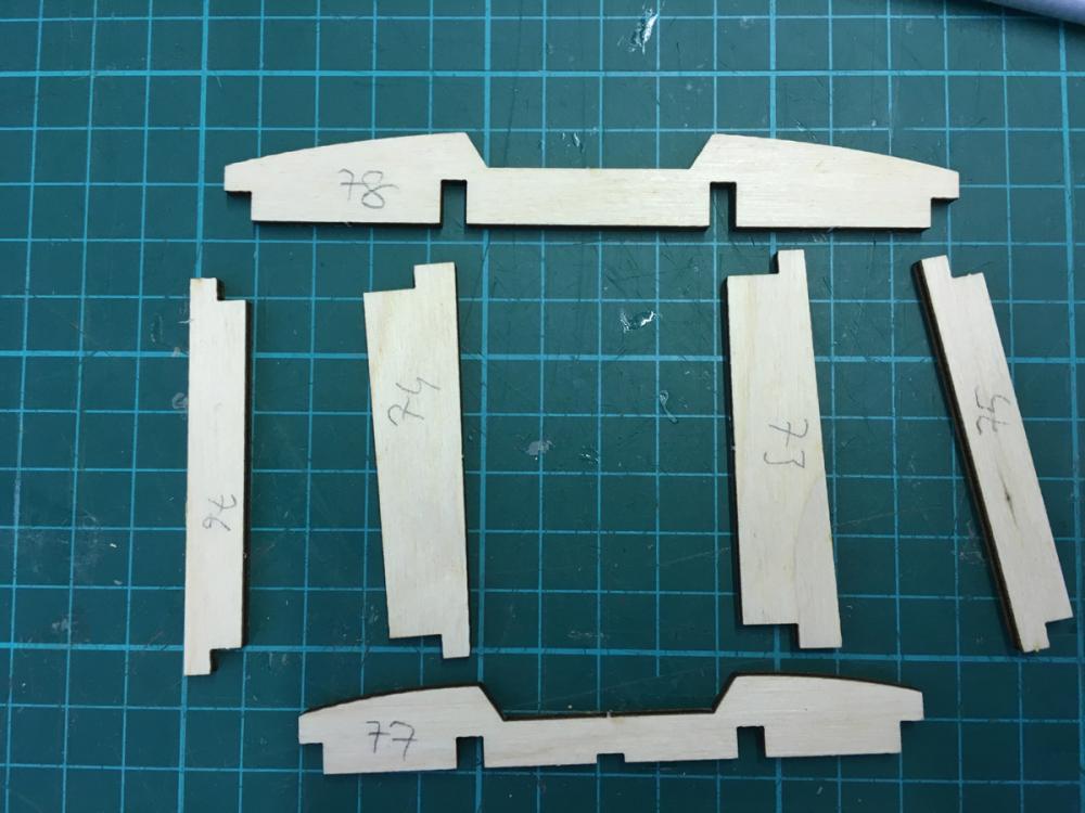
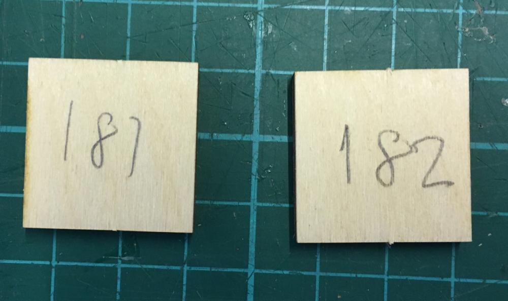
Cockpit cover parts from the sheet above. Here during dry-fit I noticed a mistake in the instruction manual. Parts 150 and 151 are labeled wrong in the photo in the manual. They should be vice versa. Otherwise they won’t fit. Or the numbering in the plan sheet is wrong, whichever. Well, this is the 2nd error in the instructions which puts me to 2-1 lead in the mistakes against the manufacturer!
- 414 replies
-
- 4
-
-
- riva aquarama
- amati
- (and 2 more)
-
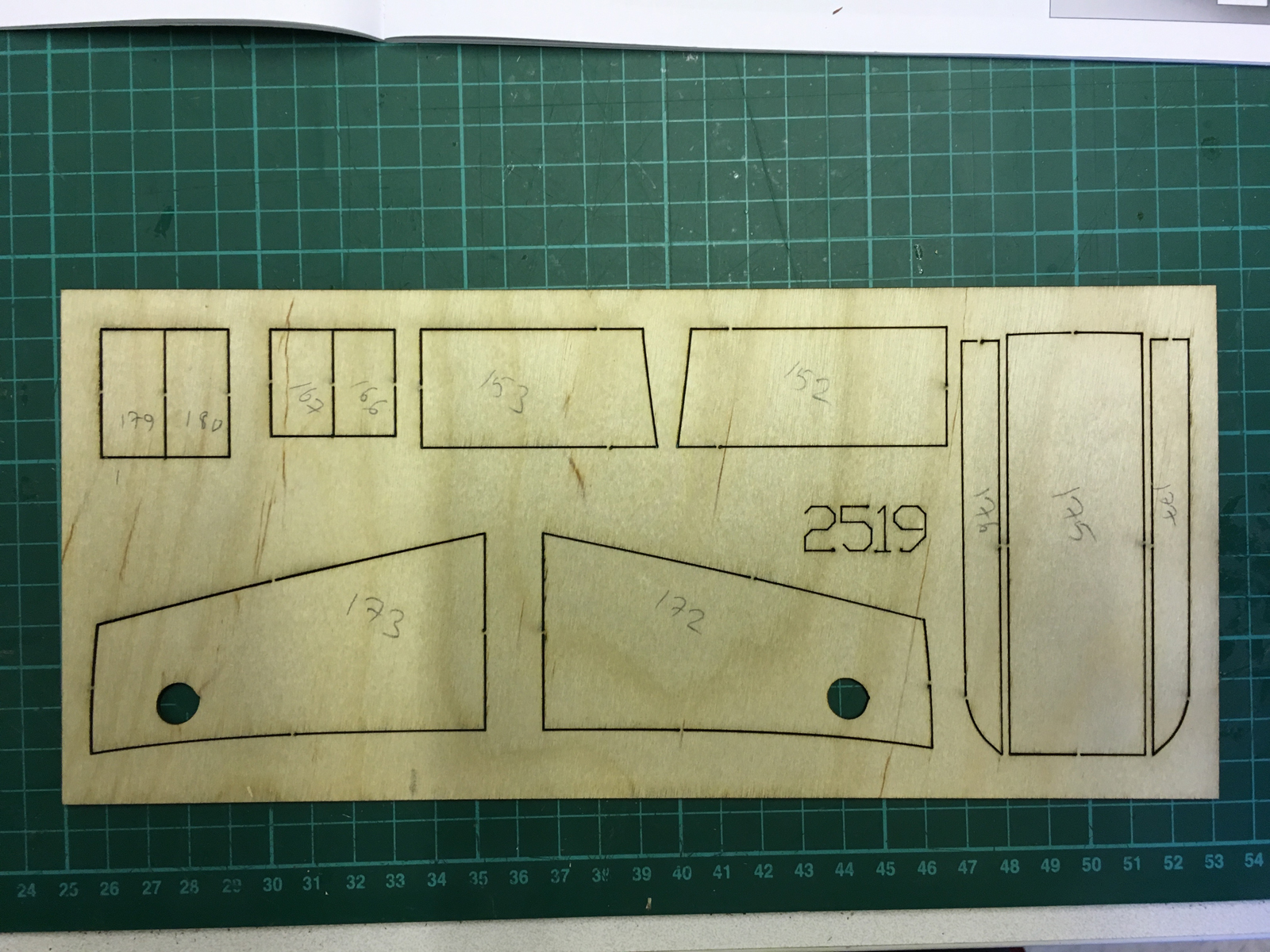
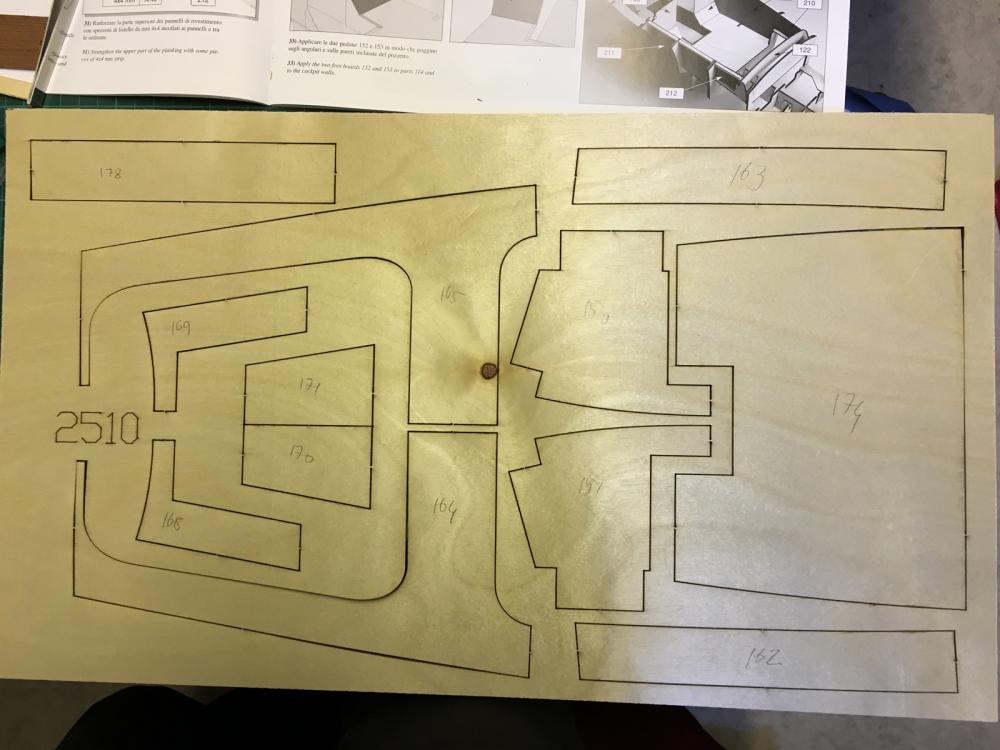
1mm high quality birch veneer sheet containing the parts for covering the hull’s plywood at more visible parts of the boat:

- 414 replies
-
- 3
-
-
- riva aquarama
- amati
- (and 2 more)
-
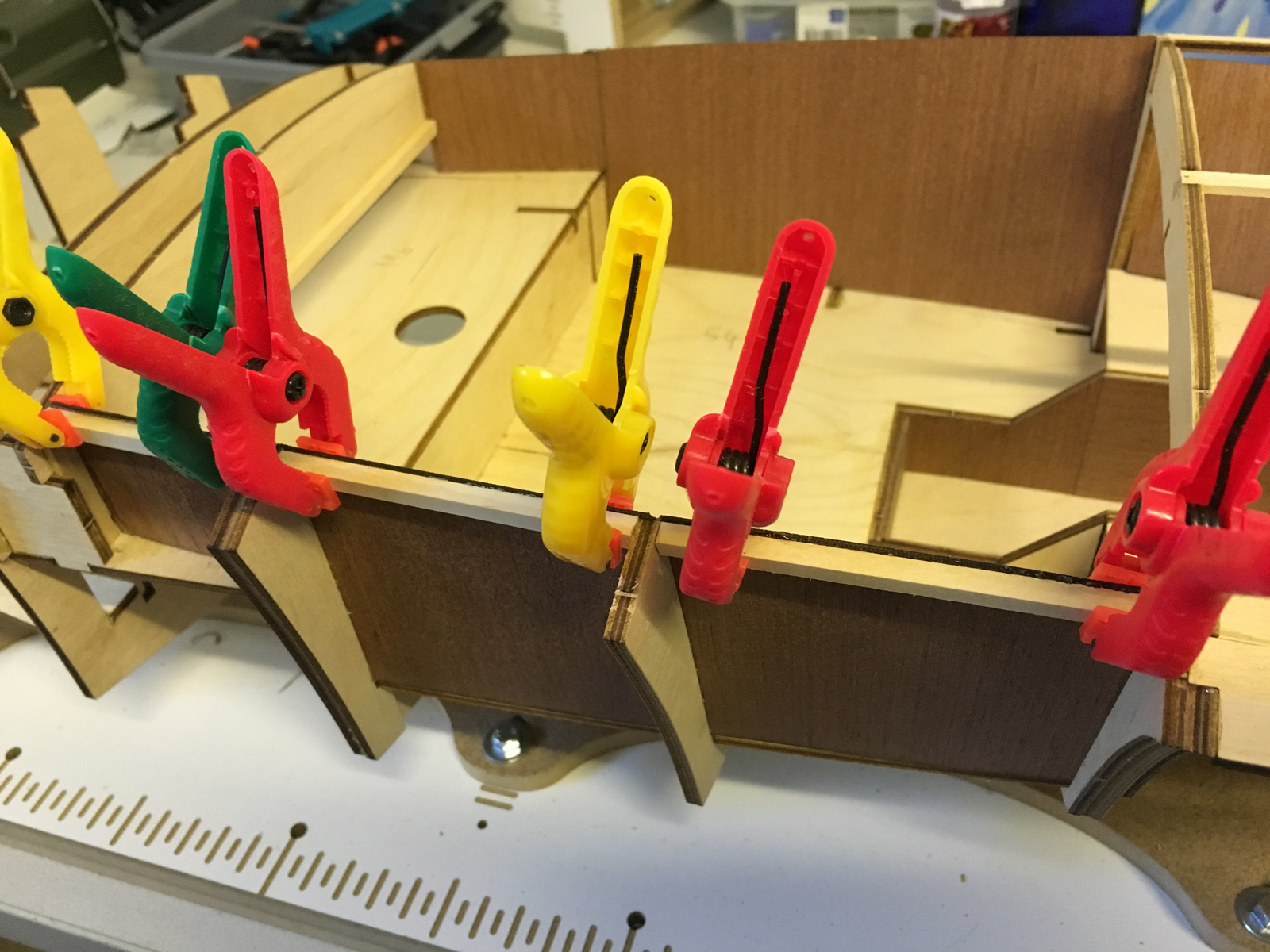
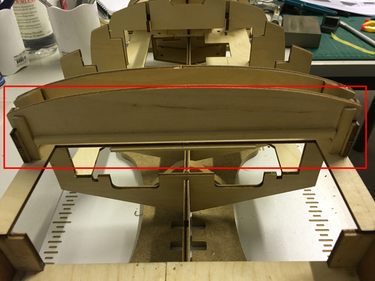
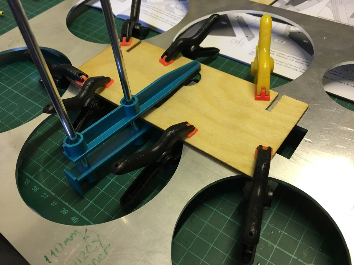
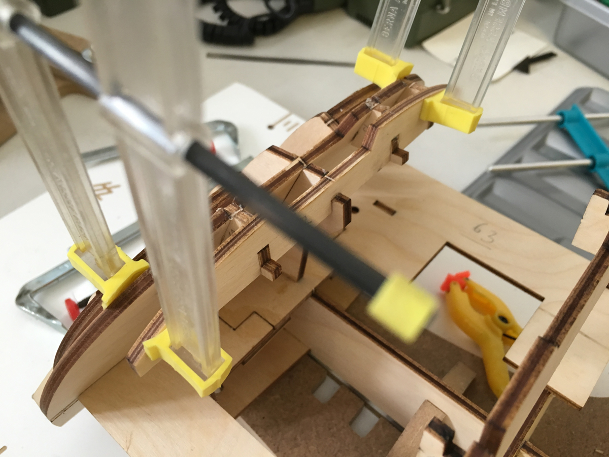
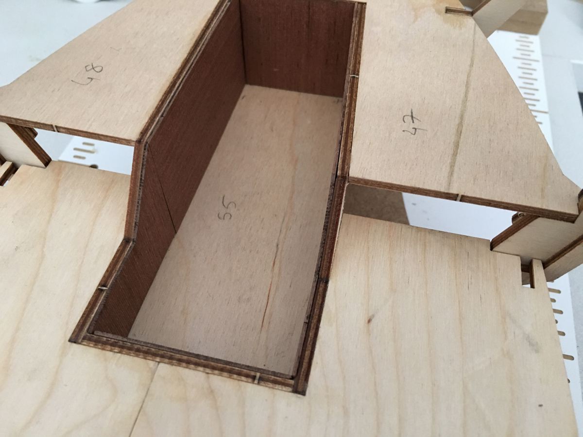
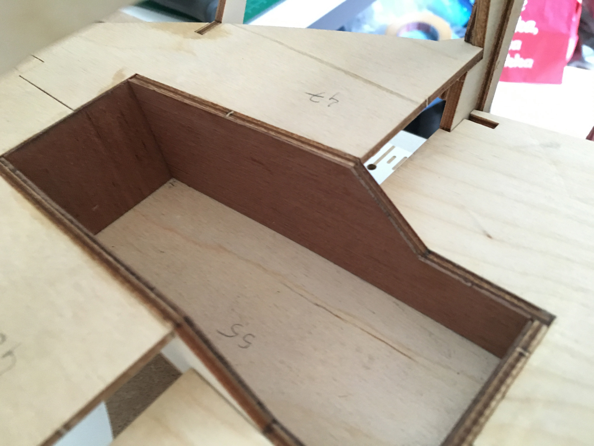
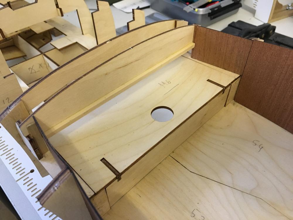
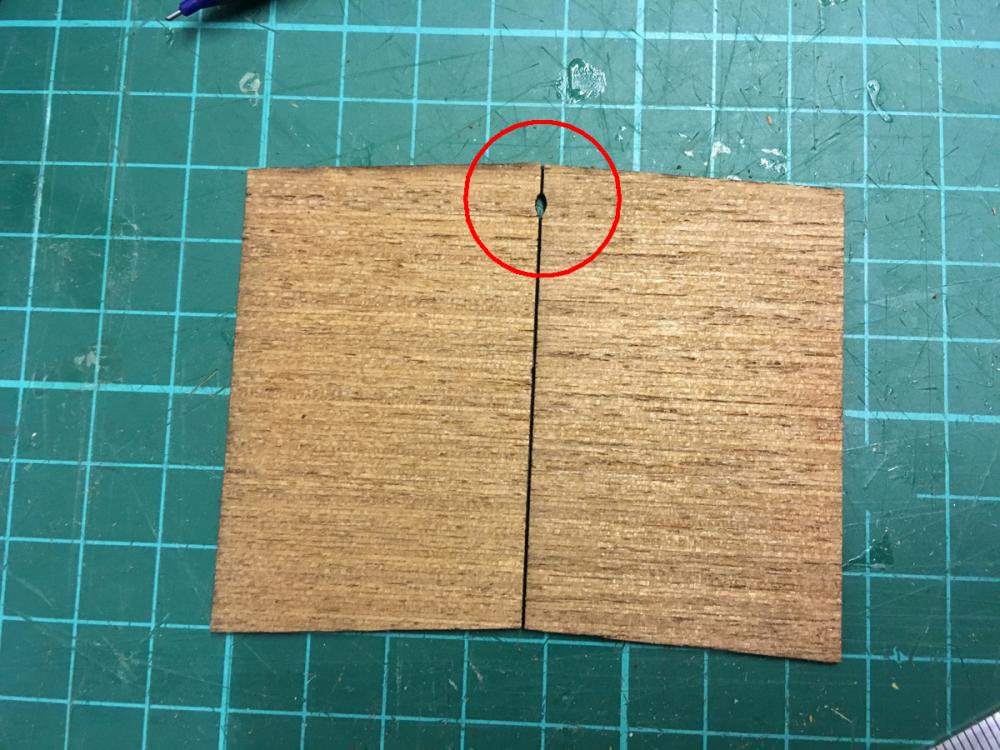
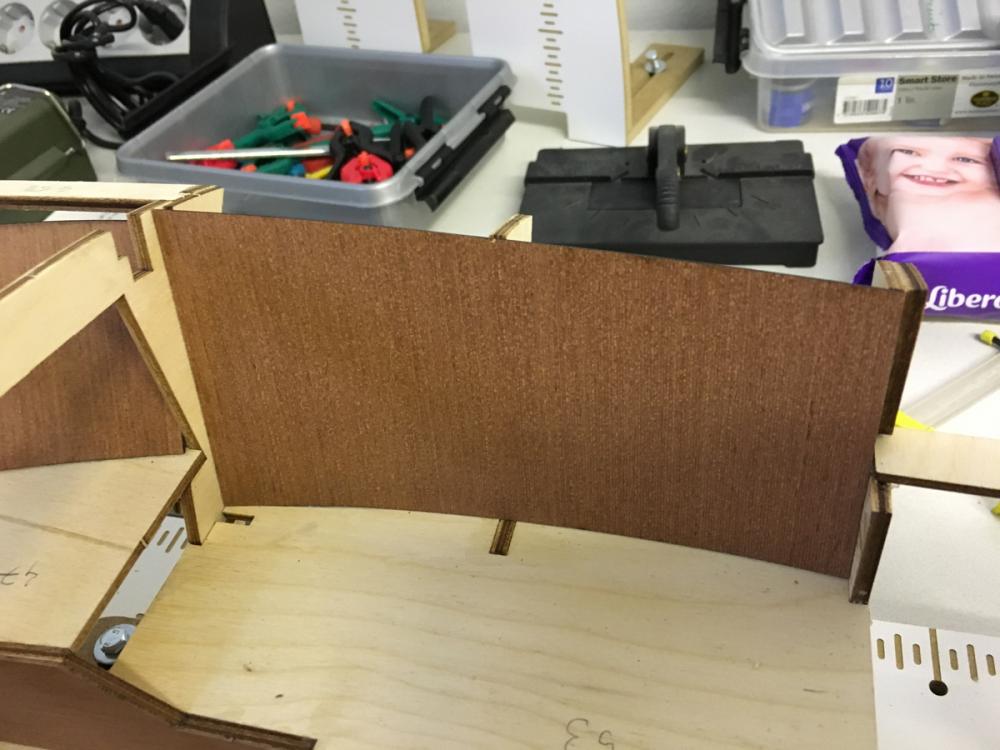
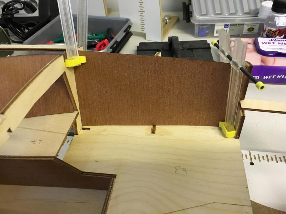
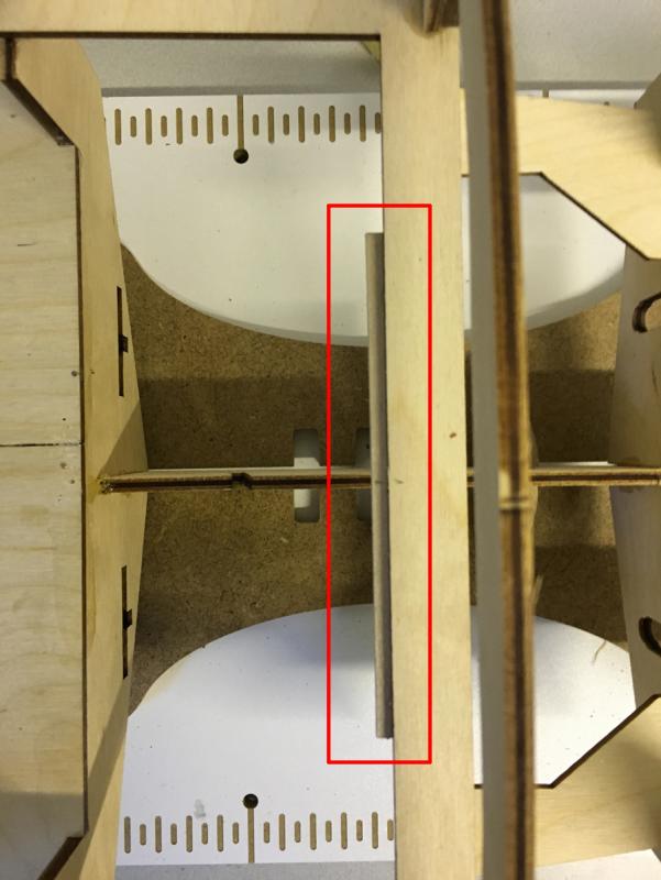
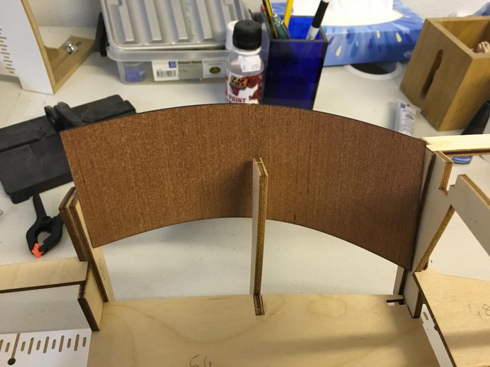
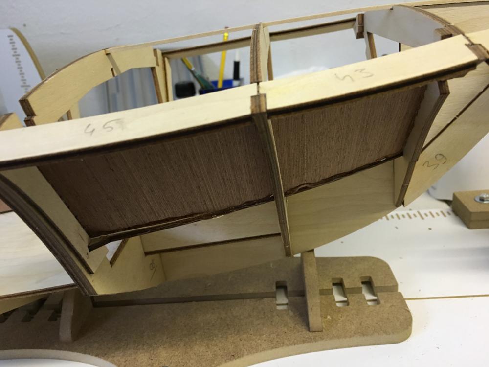
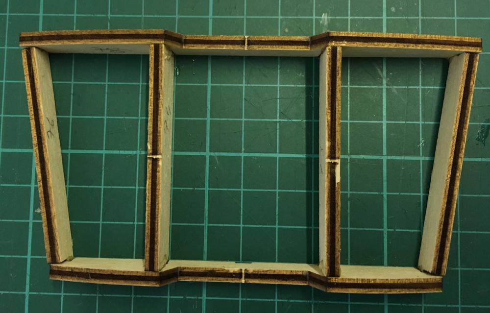
The rear seat panel, which I soaked and clamped yesterday to get it flat, is flat now and ready to be assembled. Note that the two pieces are not aligned vertically: The rear seat panel is in place. It is not glued to the place since it has to be removable (pulling by the help of the hole in the middle) to access the R/C compartment: From top: And from bottom:

- 414 replies
-
- 4
-
-
- riva aquarama
- amati
- (and 2 more)
-
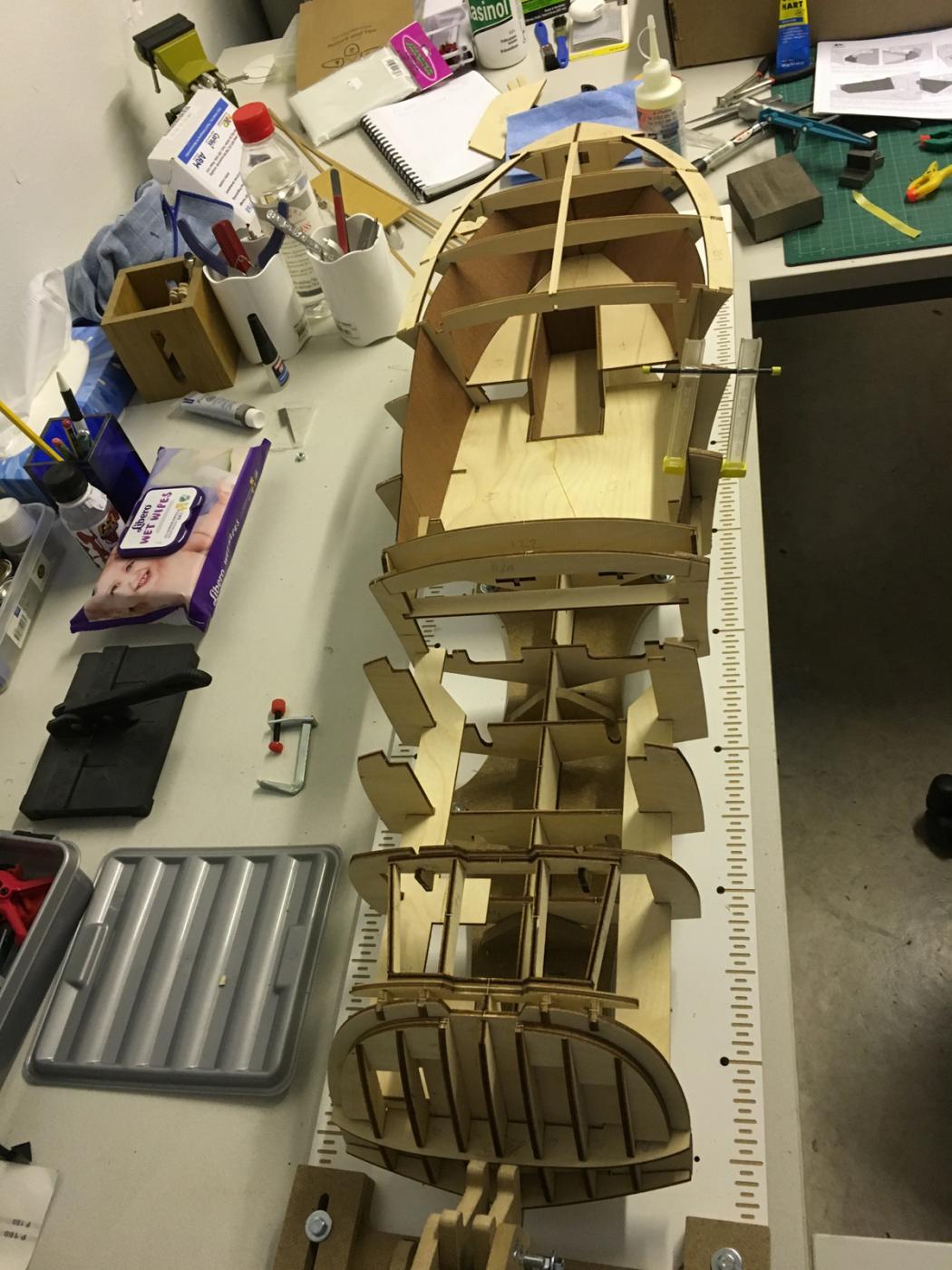
BUILD DAY 4. HULL CONSTRUCTION CONTINUED Today I had to stop earlier than I was planning for the reason I will tell later (nothing bad).
-
END OF BUILD DAY 3. 5 hours today. 14 hours into build in total. This is the status at the end of DAY3 .Thanks for watching.

- 414 replies
-
- 8
-
-
- riva aquarama
- amati
- (and 2 more)
-
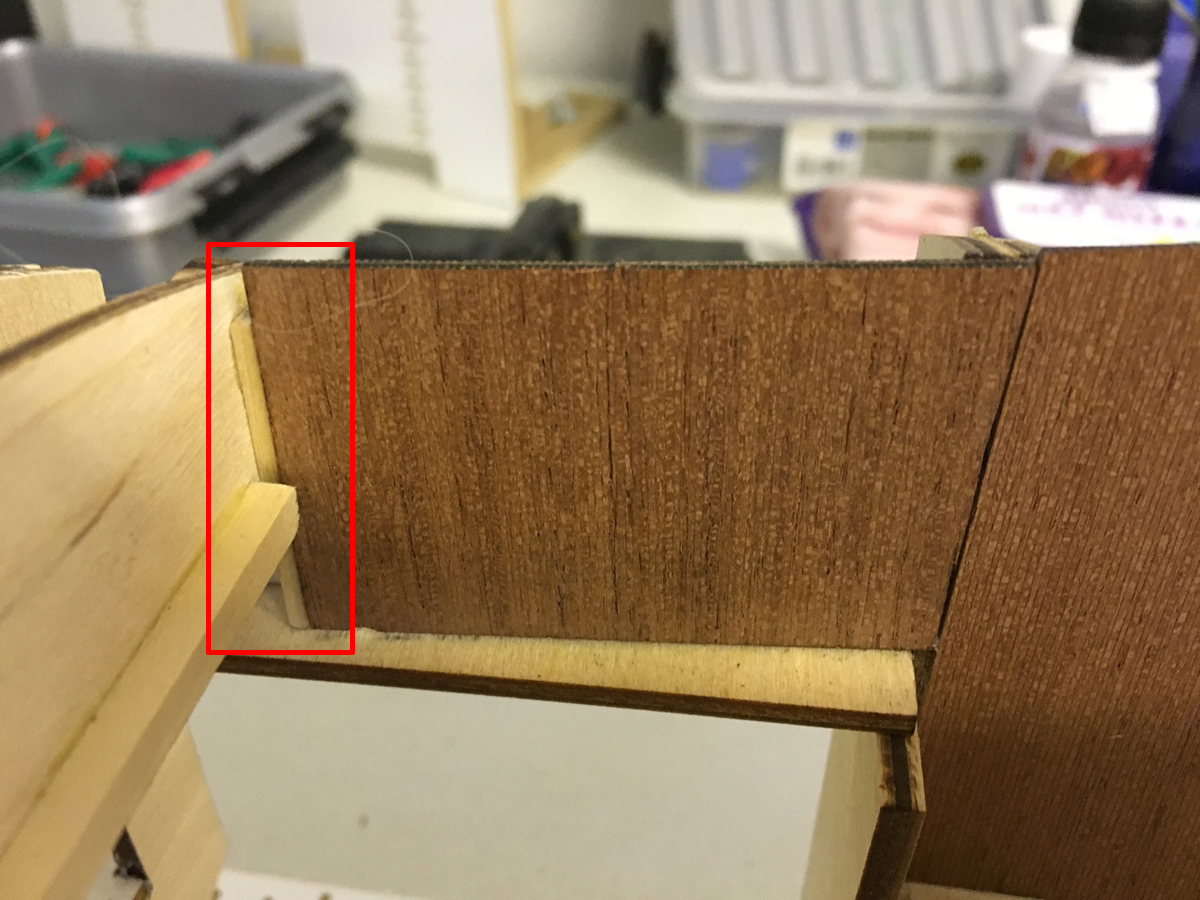
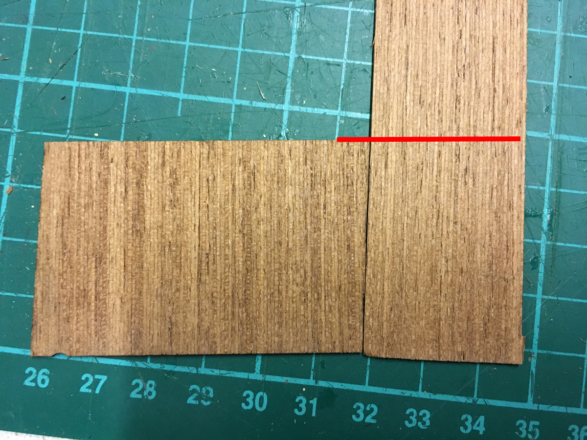
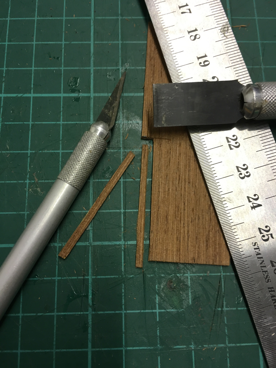
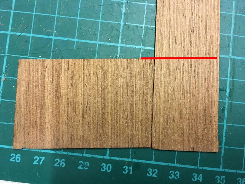
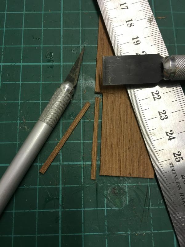
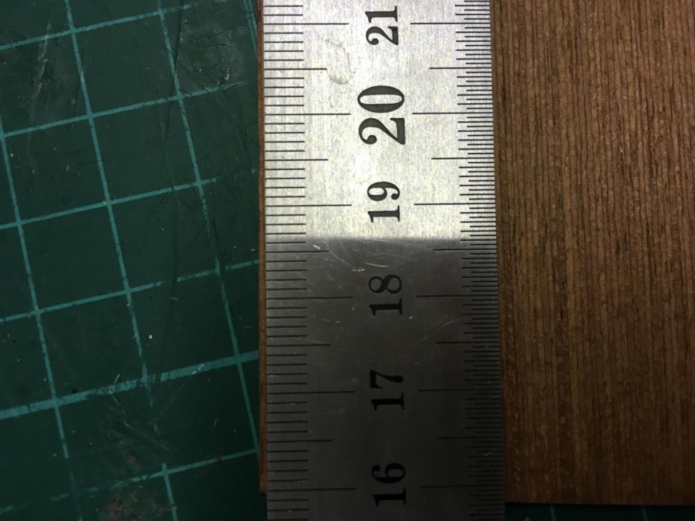
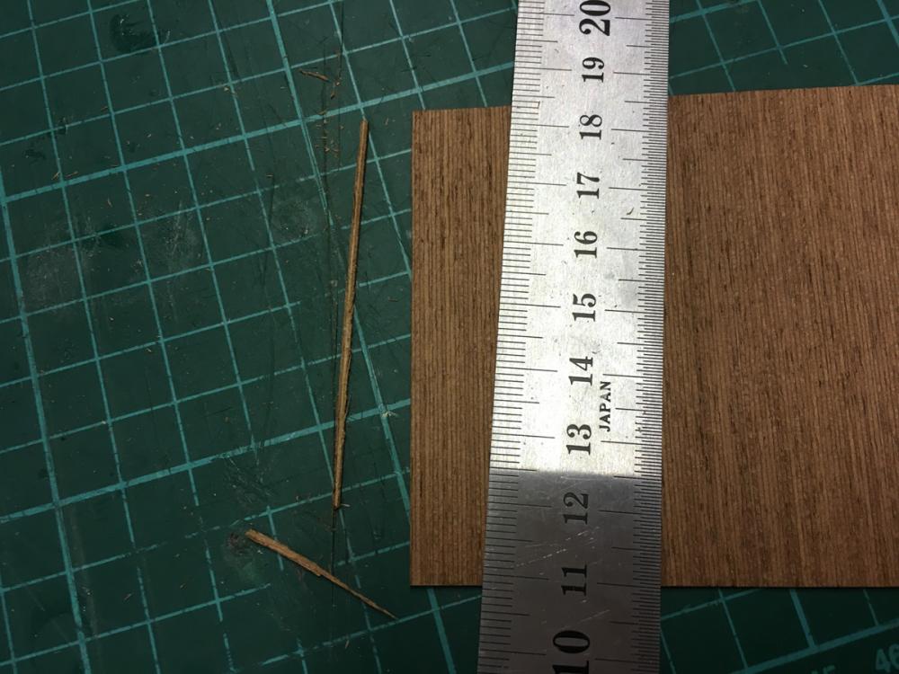
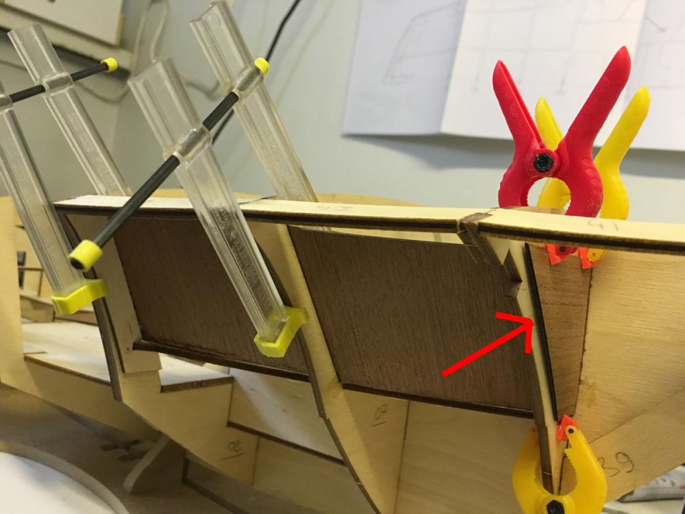
This piece came around 1mm too short, because of the adjacent sheet (on the right) which I had to trim. This will most probably not even going to be visible, but just to be a good sport, I measured and cut a thin strip from a scrap mahogany sheet and glued it in place to close the gap: Watching the direction of the grain :

- 414 replies
-
- 4
-
-
- riva aquarama
- amati
- (and 2 more)
-
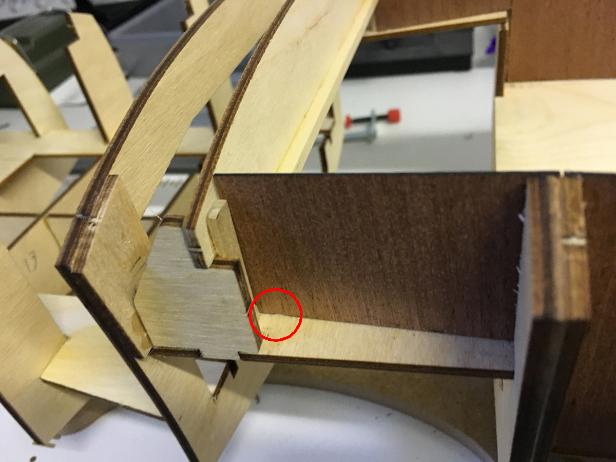
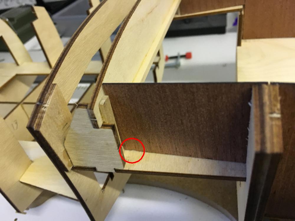
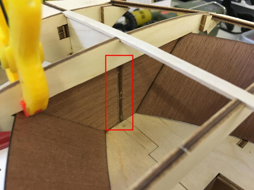
Mind the groove which I mentioned above. This is where it should be:
- 414 replies
-
- 6
-
-
- riva aquarama
- amati
- (and 2 more)
-
Thanks Per! It is also exciting to know being watched ))
- 414 replies
-
- 2
-
-
- riva aquarama
- amati
- (and 2 more)
-
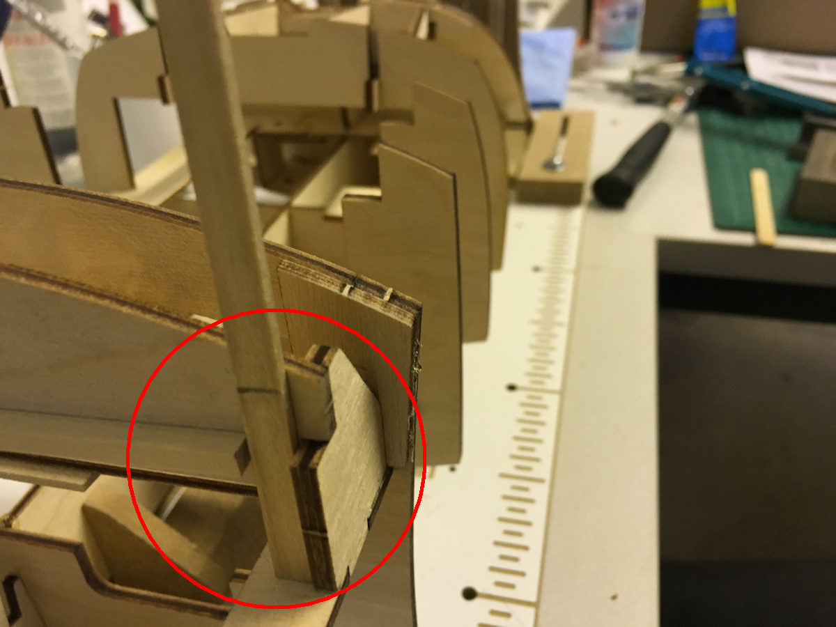
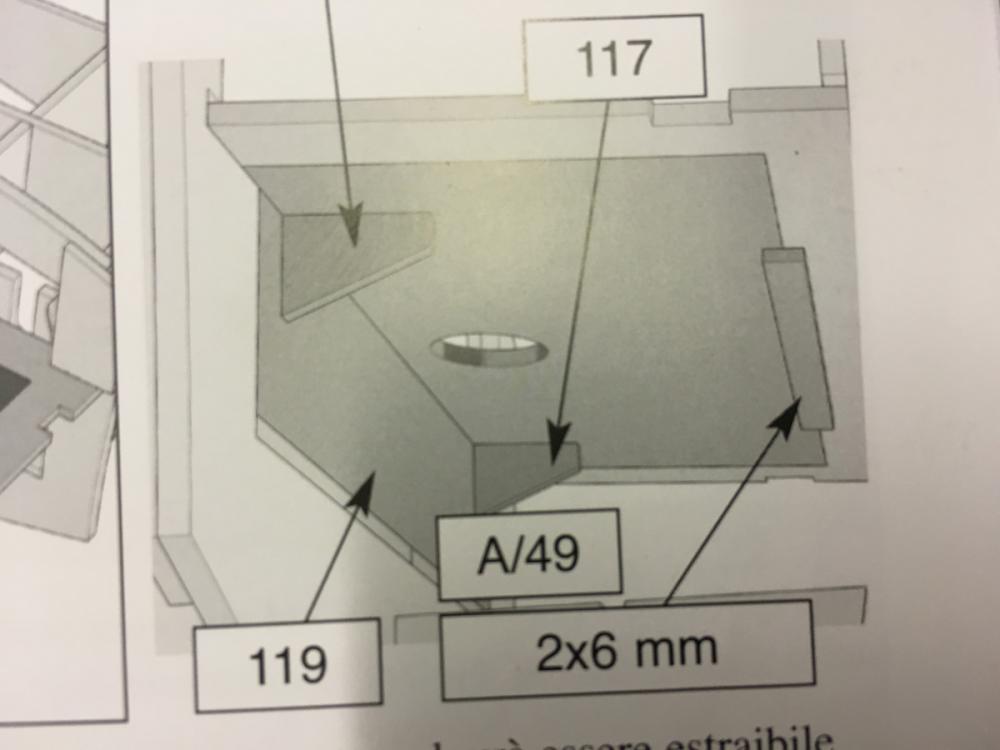
More lateral planking. Note that the parts have small groove at one end. It is essential to pay attention to orientation of the parts: Measure 2x6mm strips to act as spacers to above parts, using the plan sheet: Spacers glued in fornt of the support piece (which was temporarily fitted above - in the photo with masking tape):

- 414 replies
-
- 6
-
-
- riva aquarama
- amati
- (and 2 more)
-
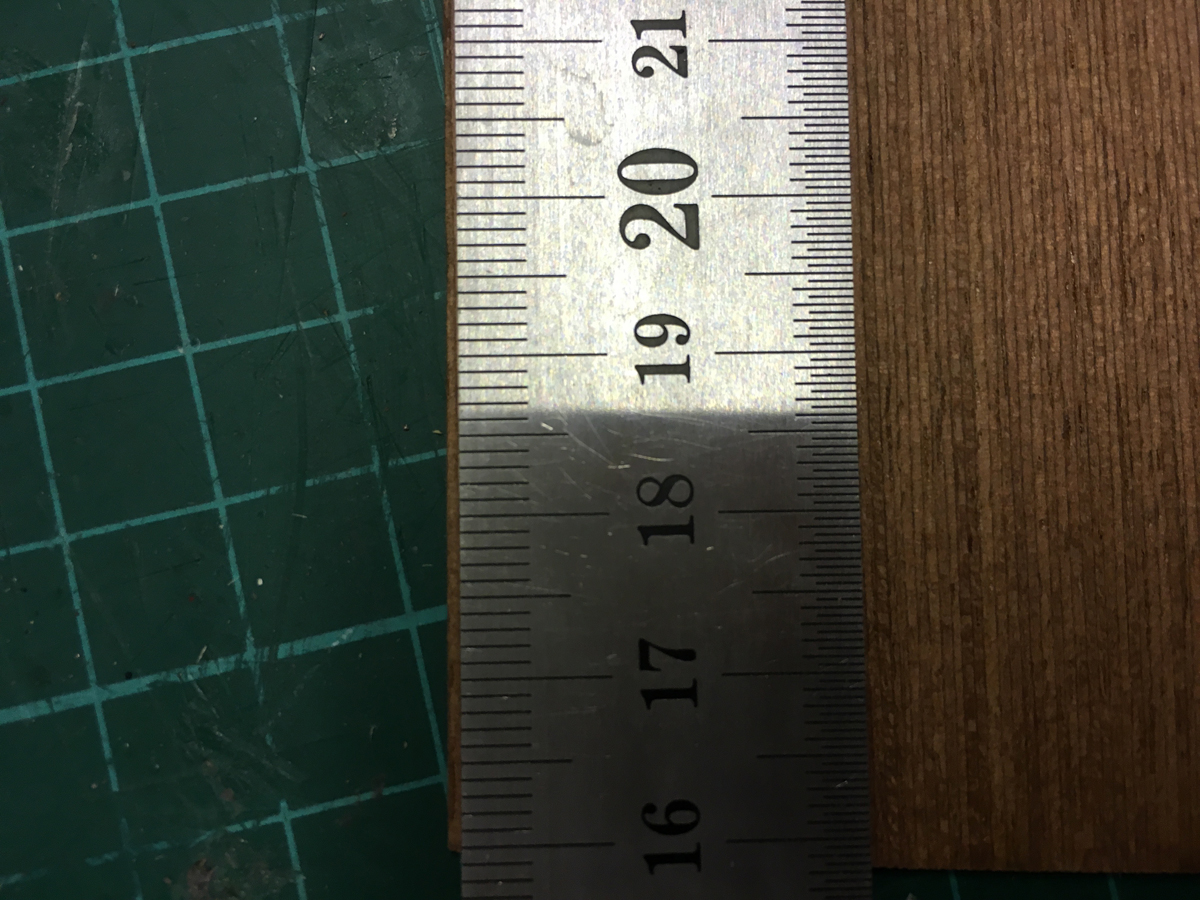
More lateral mahogany planking sheets. I had to trim some 1mm for a perfect fit. Dry fit: Measure the trim: Trim (about 1mm): Glue in place: Repeat the steps for the other side.
- 414 replies
-
- 6
-
-
- riva aquarama
- amati
- (and 2 more)
-
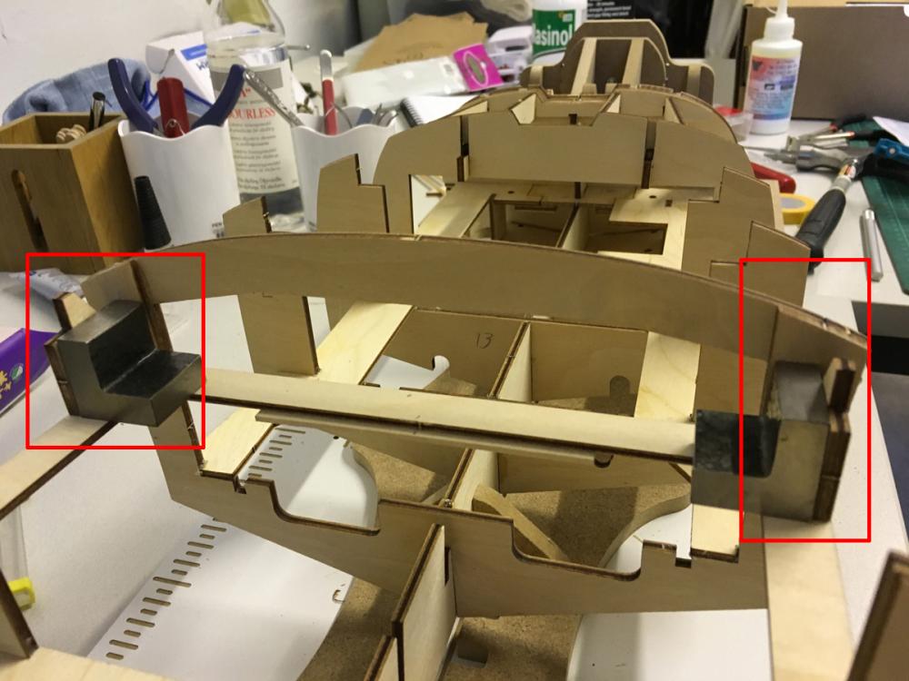
Side supports for the backseat. The small metal squares which I had bought (from micro-mark.com if I remember correct) help well in these kind of tight places to ensure the right angle. A 4x4mm lime strip to reinforce the back support for the seat. Temporarily dry-fitted until the whole thing is glued in place:
- 414 replies
-
- 5
-
-
- riva aquarama
- amati
- (and 2 more)
-
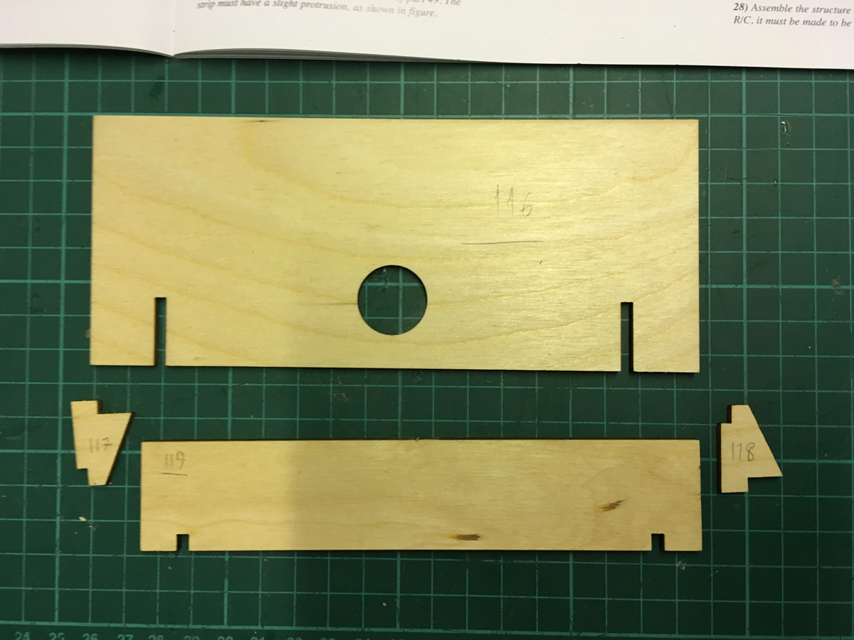
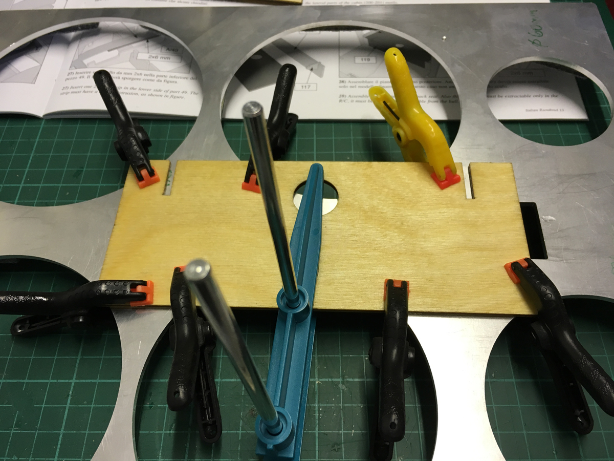
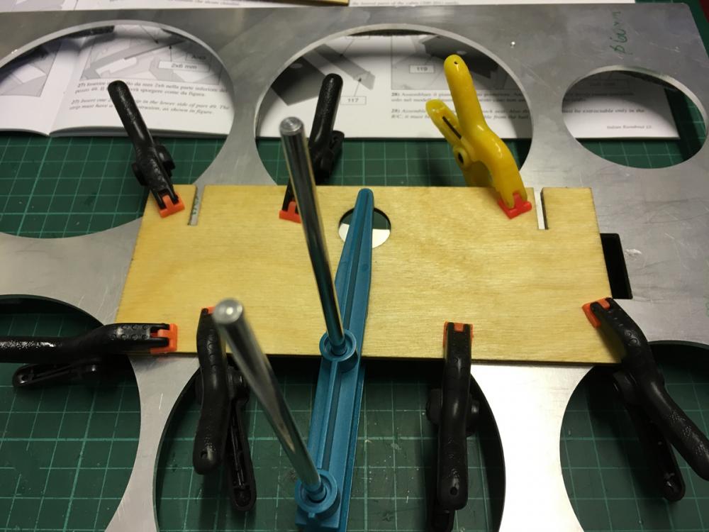
The backseat. This is also one of the pieces which should be left removable if R/C option is used. I noticed that the part 116 was not perfectly flat. It was a little bit warped (about 1mm). It would look ugly if I use it just like that. For this reason I soaked it in water for a while and fixed it with clamps on an aluminum jig which I had lying on my shelf for other project. I will wait until tomorrow hoping that it flattens. If it won't, then soak it longer time and maybe use hair dryer while it is clamped.


- 414 replies
-
- 4
-
-
- riva aquarama
- amati
- (and 2 more)
-
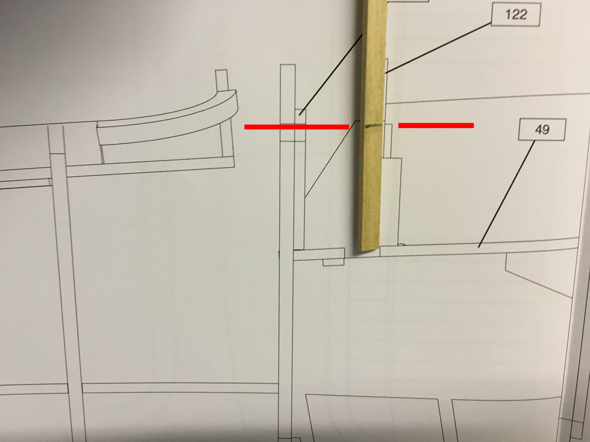
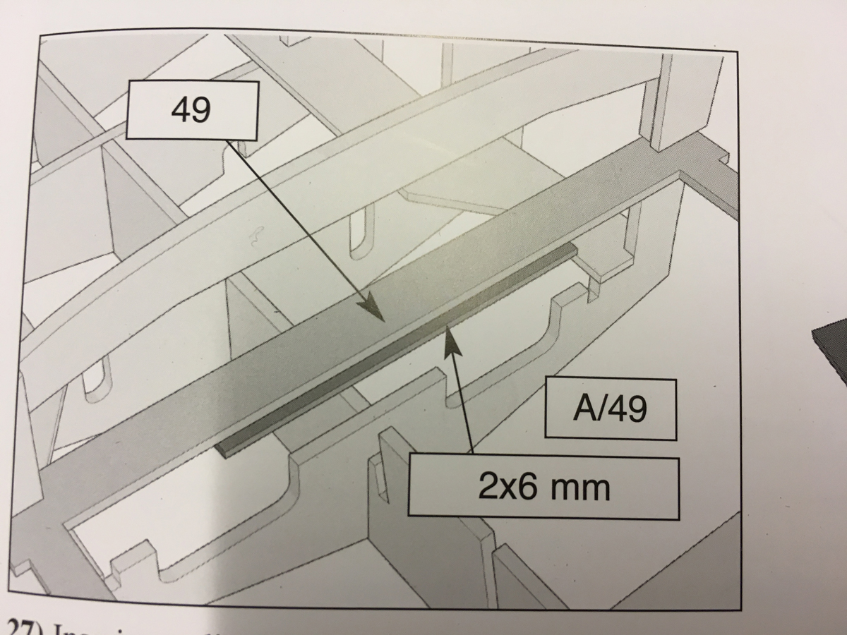
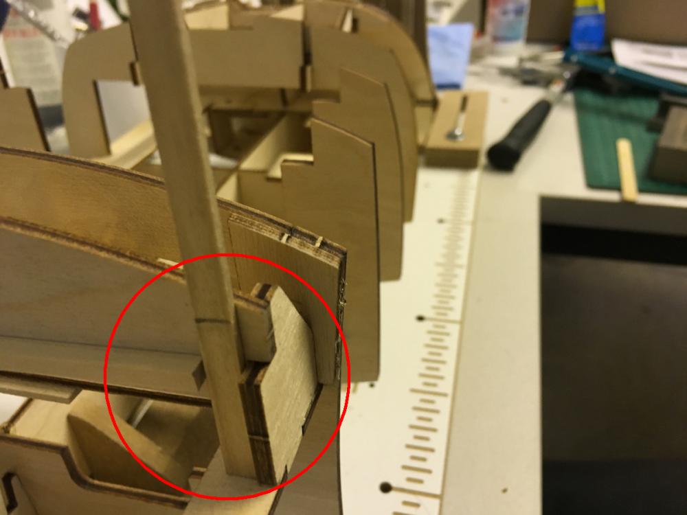
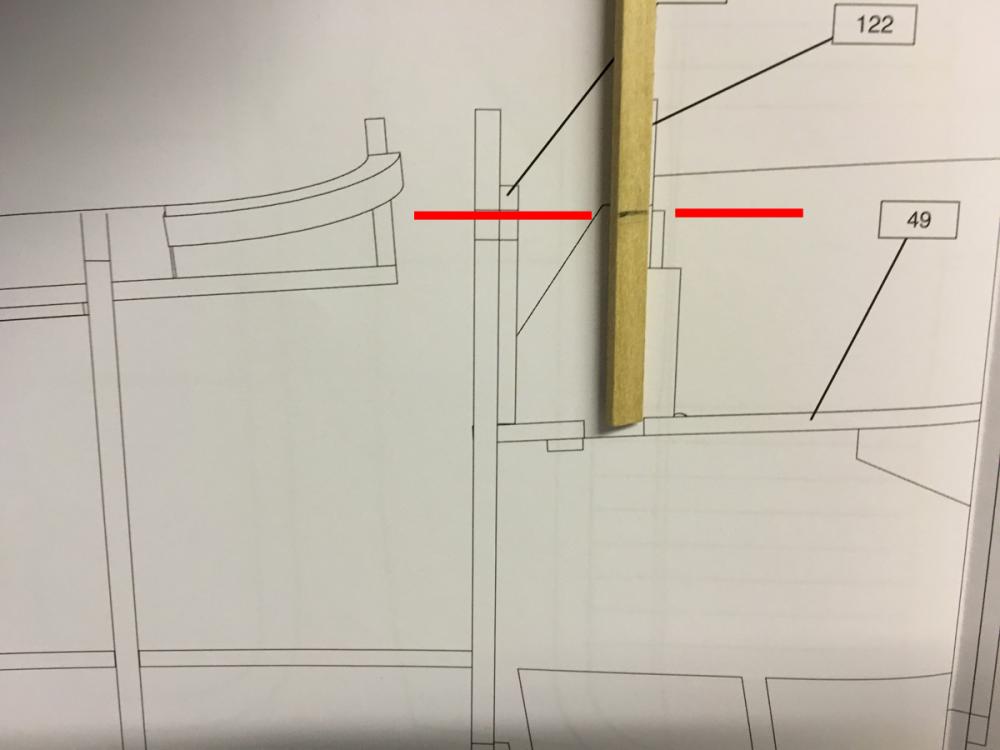
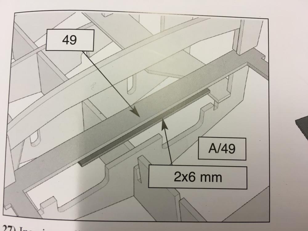
Here the instructions call for a 2x6mm strip to be glued under part 49 to act as a support to the rear seat. Checked the length from the plan and glued it as seen.
- 414 replies
-
- 5
-
-
- riva aquarama
- amati
- (and 2 more)
-
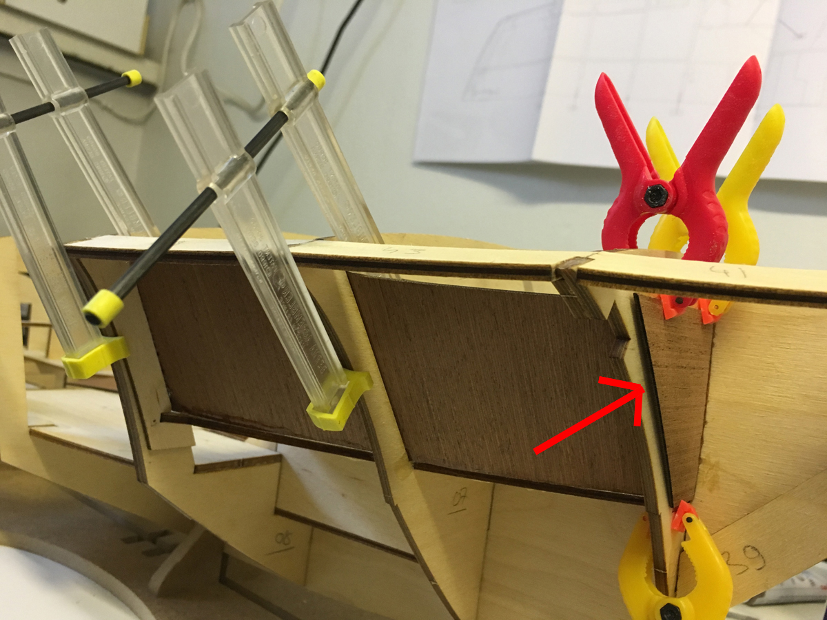
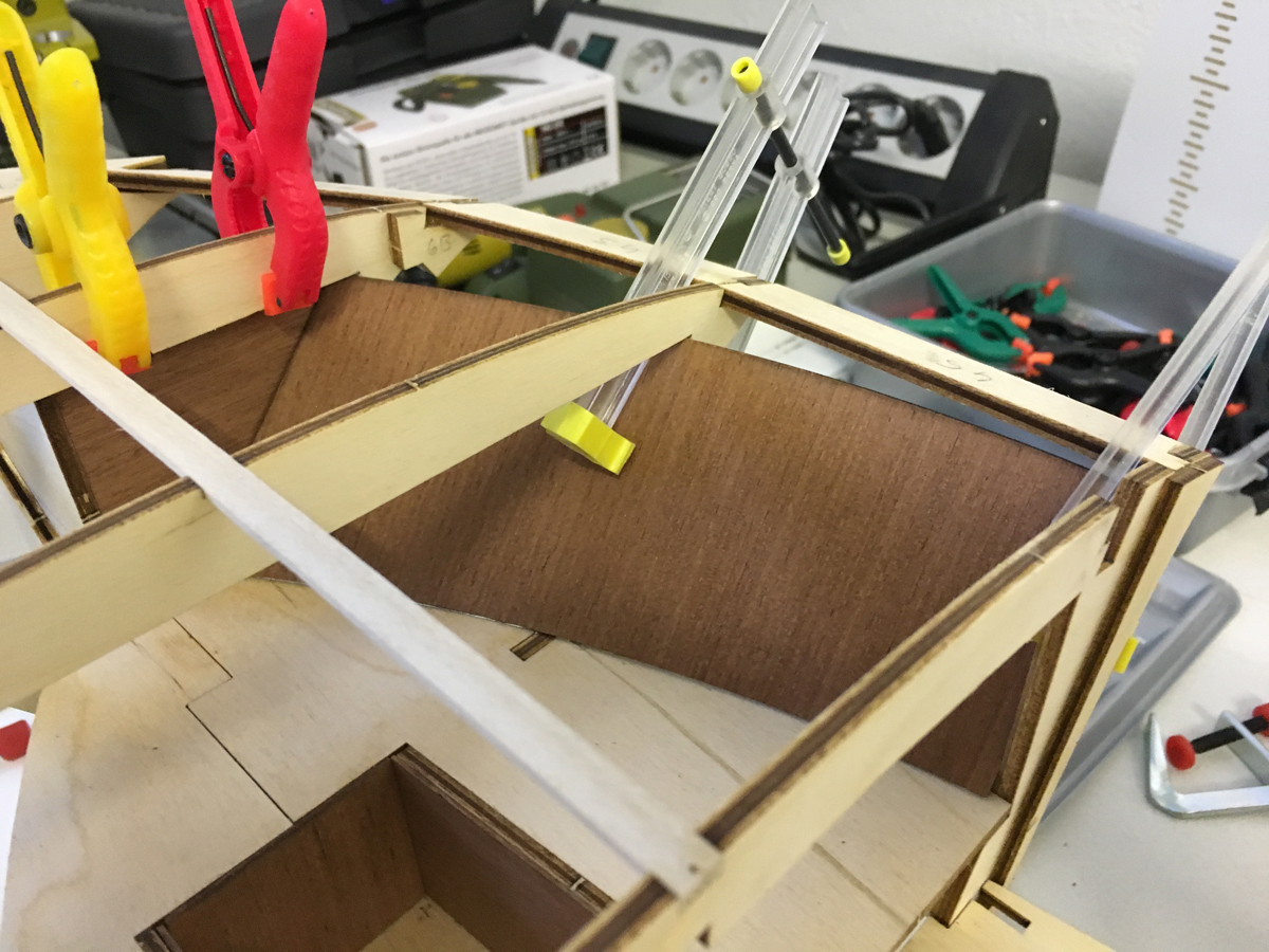
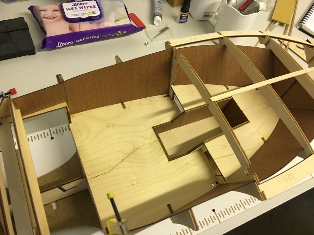
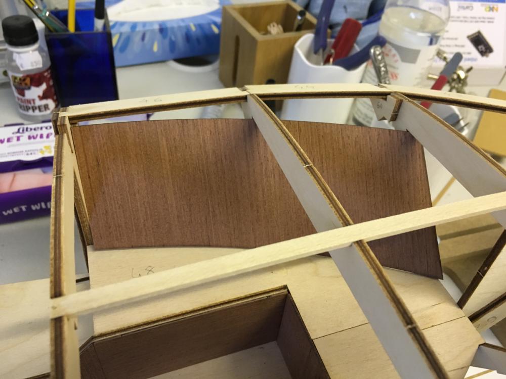
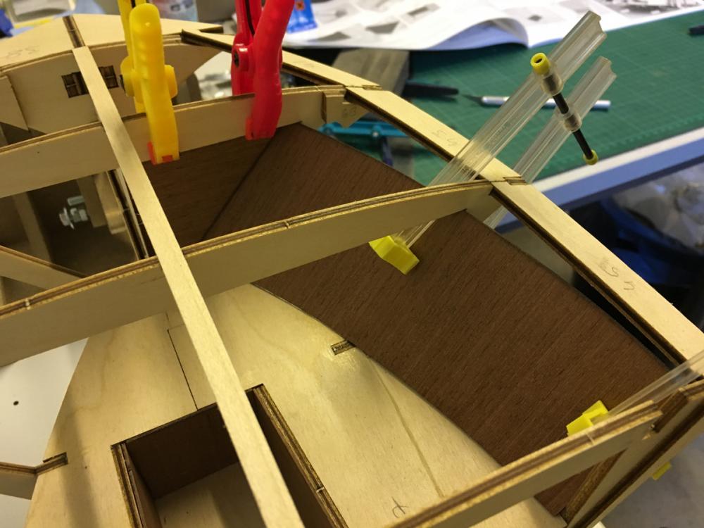
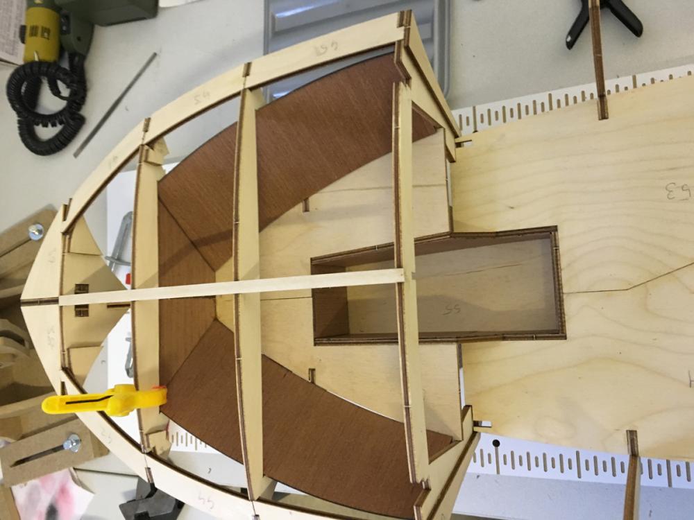
Lateral plankings of the cabin. 1mm mahogany. The instructions say you can also nail them if you like, but I preferred to avoid it, not to take the risk of cracking them all the way. Mahogany, especially at this thickness is not easy to work with. Instead, I gave it a bend with the help of the frames in order to make it easier to position without applying too much force: Dry fitted and glued: Note that the front parts (the triangular ones) should be glued from the outside: Though this leaves an uncovered section in the middle, but this is compliant with the specs. Who knows maybe it will be covered later (I was too lazy to check forward). All in place:


- 414 replies
-
- 6
-
-
- riva aquarama
- amati
- (and 2 more)
-
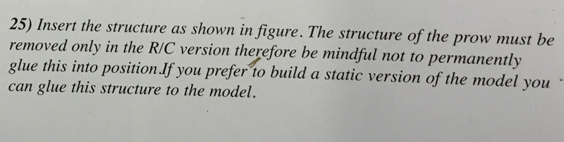
The cover itself. NOTE for the R/C builders: This cover must not be glued but be removable. I just temporarily placed it in its place to let the glue dry at its correct shape:
- 414 replies
-
- 4
-
-
- riva aquarama
- amati
- (and 2 more)
-
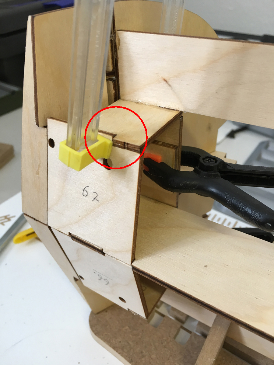
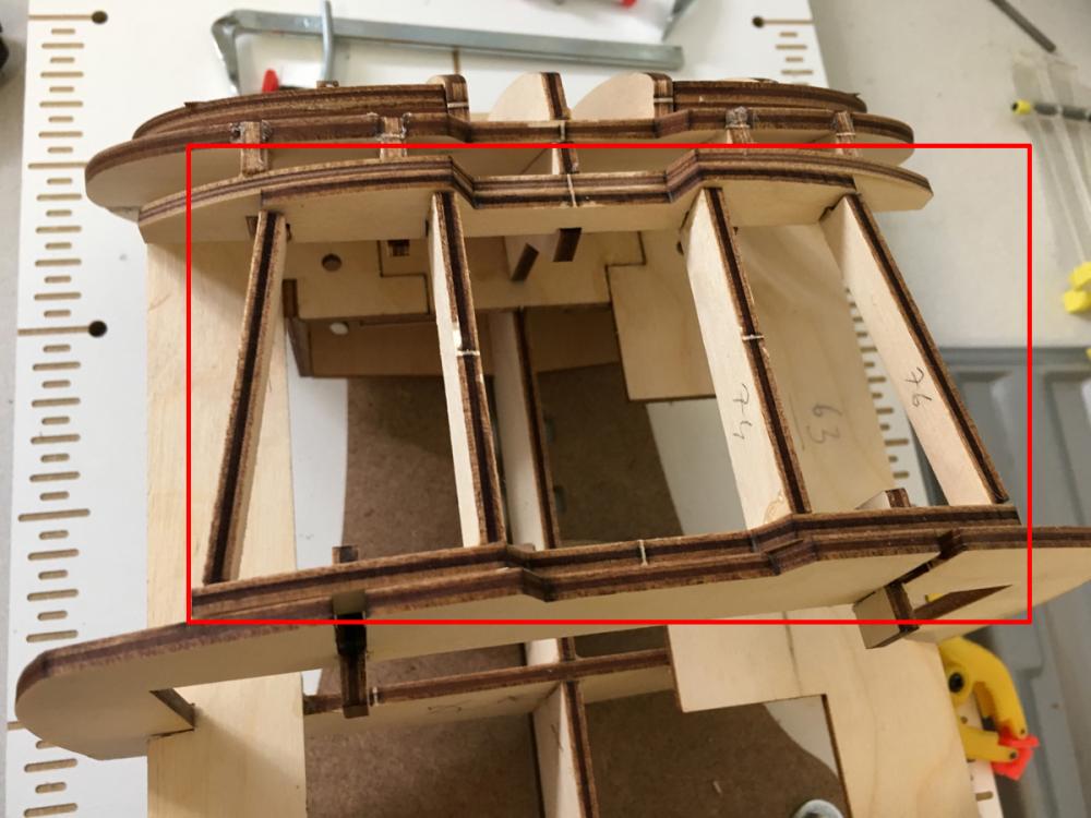
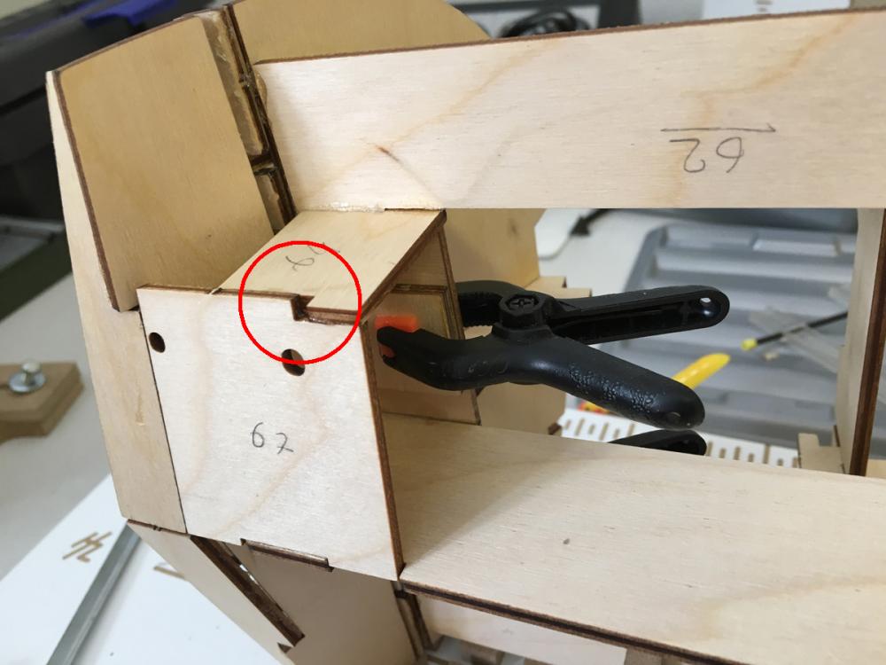
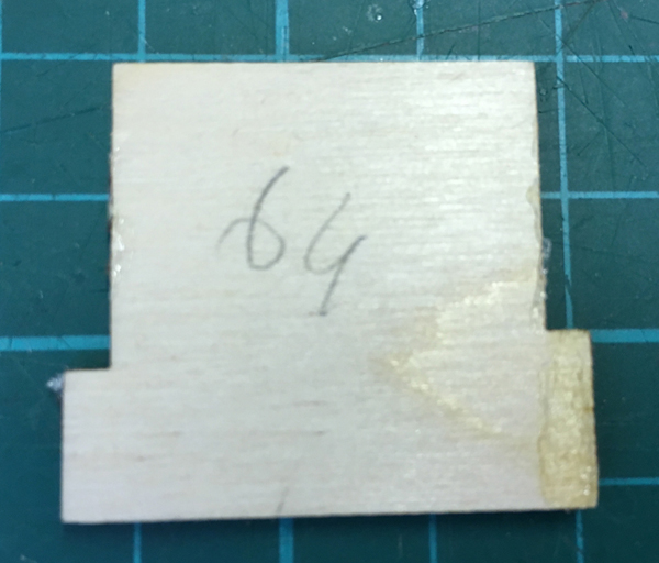
Rudder supports on the bottom. The orientation of the two holes are important. Below I was first wondering "what is the gap here? There must be a reason?!?" Then I realized I glued the part 64 wrong! (First mistake in this project - so far). Luckily it was not too bad a mistake. I ripped the part off: Scraped the glue stains, and glued it back in correct position. Now looks better (phew). This would absolutely cause me a lot of trouble later because I noticed that it was partly blocking some slots above it.

- 414 replies
-
- 5
-
-
- riva aquarama
- amati
- (and 2 more)
-
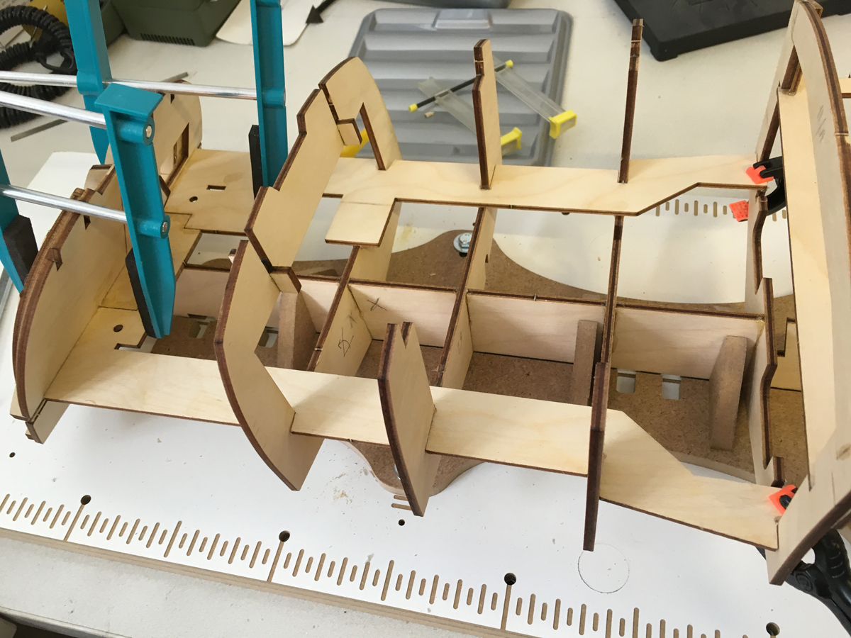
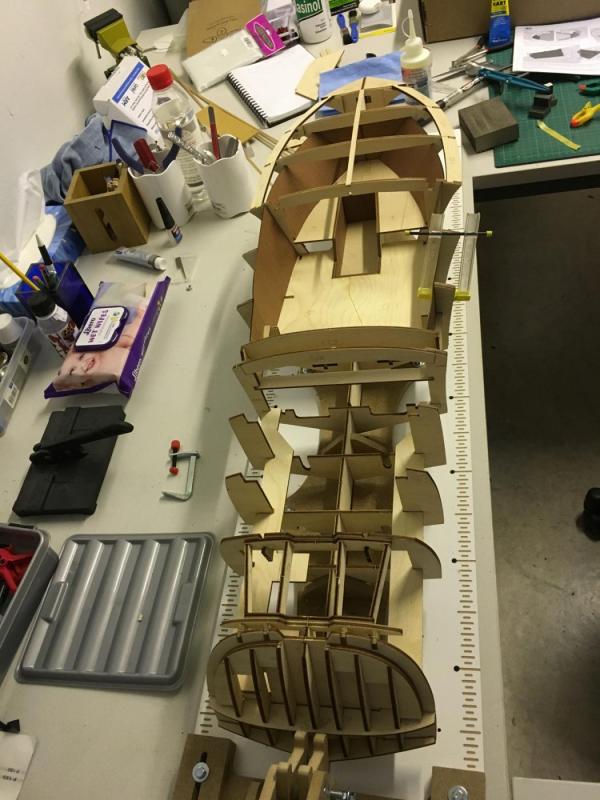
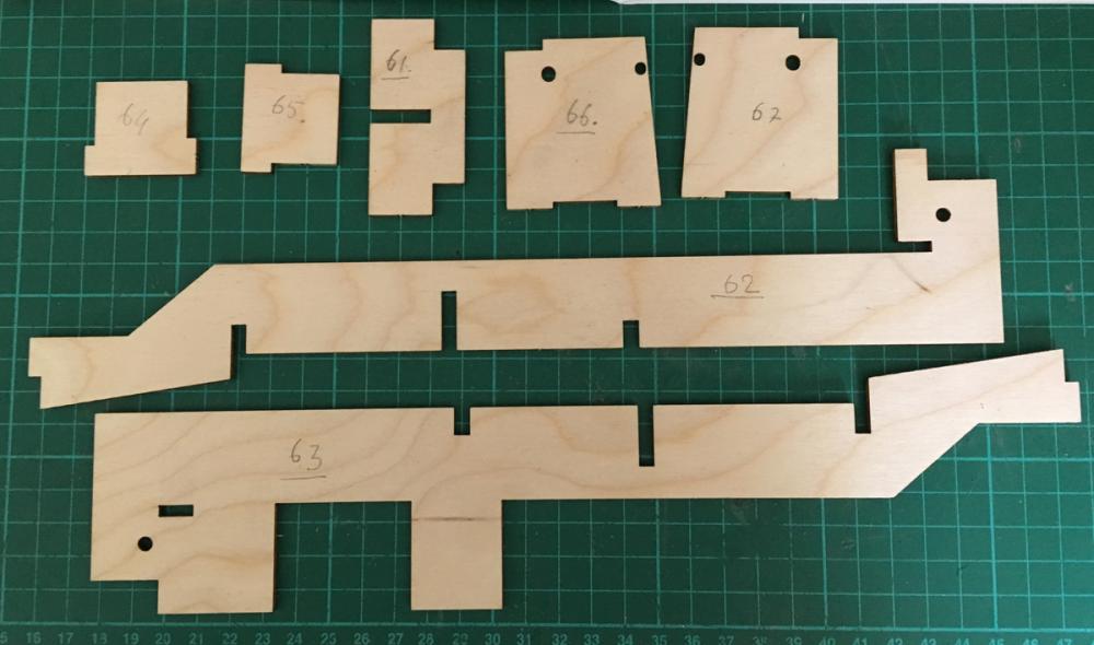
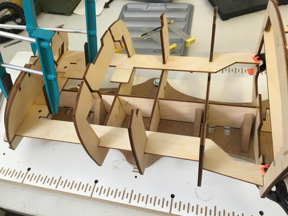
Reinforcements reinforcements everywhere . I think this kit contains alone more reinforcement parts than all my past ship kits combined. Not that I complain . Of course it should survive moderate collisions and vibrations. Here are several photos in a row: the first one with list of parts followed by the rest showing them installed in their places. Here the boat turns to side for the first time:

- 414 replies
-
- 4
-
-
- riva aquarama
- amati
- (and 2 more)
-
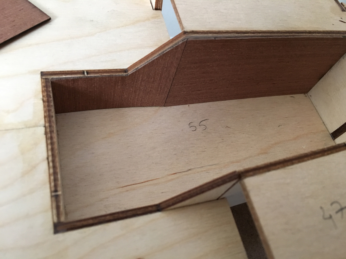
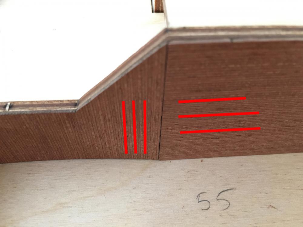
I would expect the manufacturer to pay attention to the direction of the grain when placing the parts on laser CNC. It would look much nicer if they did it:
- 414 replies
-
- 3
-
-
- riva aquarama
- amati
- (and 2 more)